1
First Edition
HotPi
A Peripheral for Raspberry Pi
Assembly and
installation
Karl Lattimer
Preface
Preface
The HotPi is a project that was started in December 2012 by
the author and launched that month via Kickstarter. The project
successfully reached it’s funding goals by January of 2013 and
completed distribution of the pledges in September 2013
slightly behind schedule.
Designing the HotPi was a pleasure as the design was simply a
personal endeavour, it became clear however that this product
was so packed with features a kickstarter made obvious sense.
Taking the HotPi through the design and development alone
was quite a challenge but not as challenging as distributing so
many parcels to so many addresses with all of the options
offered. As a result of the necessary effort the kickstarter
slipped in schedule.
The size and simplicity of the hardware has made the HotPi
popular with RaspberryPi enthusiasts. The author wishes the
reader the best of luck when assembling and using the HotPi in
the way it was intended and in true maker style any corruptions
of that purpose.
The HotPi is available exclusively from ThePiHut for
around £11.
ii
Copyright notice
© Copyright Karl Lattimer 2013
All text, diagrams and photographs contained in this manual are the sole intellectual
property of Karl Lattimer. With the exception of “Soldering is Easy” cover which is
used under the Creative Commons, and further exceptions covering the User
Photographs included in the appendix which are the property of the respective
named parties.
No part of this user guide should be reproduced independently without the consent of
the Copyright owner, this document is provided freely in entirety for the benefit of
HotPi customers and it is intended to be shared digitally among those who find it
useful.
A condition of this copyright is that the document is not reproduced in part or parts of
this document used in ways which have not been officially sanctioned by the author.
iii
HotPi assembly
1
This simple and short
guide will include all you
will need to know in order
to build a HotPi peripheral
for your RaspberryPi
computer.
Section 1
Preparation
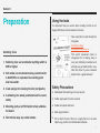
Using the tools
It is important that you use the tools correctly, but this is not
hugely difficult and can be learned in minutes.
Take some time to read through the
free guide
Soldering is Easy
http://mightyohm.com/soldercomic
Soldering Tools
This world renowned comic is
recognised for for being easy to
read and brilliantly illustrated and
will help you get started with in very
little time. Even if you’ve soldered
before this is a great refresher!
1. Soldering iron, we recommend anything which is
25W or higher.
2. Soft solder, we recommend using a solder which
is 60/40 PbSn or equivalent low melting point
lead free solder.
3. A wet sponge for cleaning the iron (not plastic).
4. A soldering iron stand, positioned well to ensure
safety.
5. Mounting putty or a PCB holder to help stabilise
the board.
6. Fan to blow away any solder smoke.
Safety Precautions
•
•
•
•
•
Remember that soldering irons are very hot.
Solder stays liquid for a few seconds
Solder can splash and burst
Wear eye protection
Do not touch the tip of the iron, or apply the iron to un-safe
objects e.g. plastics and inflammable materials.
5
Section 2
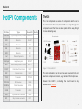
HotPi Components
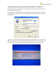
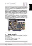
The Kit
The kit is comprised of a series of components which need to
be soldered into the board, the HotPi uses only through hole
components and the holes are also plated all the way through
to make soldering easy.
Part Code
Type
Board ID
Quantity
RGBCLED
Light Emitting Diode (Cathode)
RGB LED
1
220R
Resistor
R4-R7
4
47R
Resistor
R2
1
10K
Resistor
R3
1
100R
Resistor
R1
1
0.1uF
Tantalum Capacitor
C1
1
3.5 SJ 5pin
Headphone jack
IROUT
1
VBATT
Vertical Battery Holder CR2032
BATT
1
DS1307
Dallas Real Time Clock
1307
1
Figure 1.1: The HotPi Kit
8DIP
IC Holder 8 pin
1307
1
TIP122
Transistor
TIP122
1
The parts included in the kit can be easily sourced from most
electronic component stockists, e.g. farnell or RS Components.
TSOP1838
IR Receiver
1838
1
32.768Khz
Crystal Resonator
XTAL
1
2N2222
Transistor
2222
1
MOL3
3 pin Molex fan connector
FAN
1
26F
26 pin female connector
RPI
1
Female Header
DS1307 & Holder
220R
XTAL
10K
Capacitor
FAN
1838
IR Socket
Battery
Holder
TIP122
2n2222
Circuit Board
47R
100R
LED
However the HotPi kit, including the circuit board is only
available from ThePiHut
6
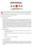
The Circuit Board
The HotPi is designed to be assembled in one of two ways, as
a female board which can be inserted into a raspberry pi as a
“piggy back” peripheral, or alternatively it can be assembled as
a male board* and connected to the raspberry pi via a 26 pin
ribbon cable.
* Please note that in order to assemble the HotPi with a male header you should
purchase a length of male header pins 13x2 and a 26 pin ribbon cable. Usually
male header pins come in longer lengths but can be snapped to size fairly easily.
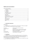
Figure 1.3: Assembled female and male boards
Once assembled your board should look like those pictured in
figure 1.3. The assembly should take no longer than 40
minutes. For a well practiced novice.
GPIO Interface
The HotPi connects to the
RaspberryPi via the GPIO
interface port. The connections
on the port are shown in figure
1.4.
Figure 1.4: GPIO Pinout
(top view)
Figure 1.2: The PCB Top Side
Figure 1.2: The PCB Bottom Side
7
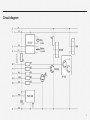
Circuit diagram
8
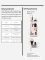
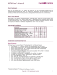
Parts grouped by feature
HotPi Physical Dimensions
The HotPi combines a lot of features in a single board, however
not everyone might want to use all of the features. In order to
assist owners of a HotPi in building just the features they want
included here is a list of the features and components which are
associated with those features.
Feature
Part codes
Real Time Clock
DS1307, 8DIP, 32.768Khz
(XTAL), VBATT
IR Receiver
100R (R1), 0.1uF (C1),
TSOP1838
IR Transmitter
3.5 SJ 5pin (IROUT), 2N2222,
47R (R2), 10K (R3)
RGB Status LED
RGBCLED, 220R (R4, R5, R6)
Fan controller
220R (R7), MOL3, TIP122
9
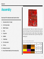
Section 3
Assembly
Overview Of The Recommended Insertion Order
1.
Resistors first (7 in total)
2.
8 Pin Chip holder
3.
IROUT Socket
4.
XTAL
5.
Capacitor
6.
2N2222
7.
TSOP1838
8.
Fan Connector
9.
TIP122
10. Battery Connector
11. 26 pin female header (on the reverse side)
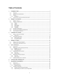
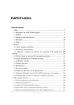
Insert the resistors first. There are 7 resistors in total, you will
need to trim the legs of the resistors immediately after soldering
them to ensure the board is usable. Having 14 legs dangling
out of the back of the board is sure to get in the way of your
soldering iron.
Figure 1.7: Resistor Identification Guide
1
2
3
Value
Position
100R
R1
10K
R3
47R
R2
220R
R4-R7
10
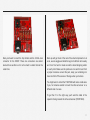
Next you’ll want to insert the chip holder and the 3.5mm Jack
connector for the IROUT. These two connectors are almost
level with one another so it’s not too hard to solder them at the
same time.
Next up we’ll get most of the rest of the small components in at
once, we can wiggle and bend the legs to hold them all in easily
and it isn’t too hard to rotate around the board dropping solder
on each point. Make sure the points are nice and hot and form
a proper meniscus around the pad, keep your soldering iron
clean and trim off the excess of the legs when you’re done.
You might want to attach the TSOP1838 with some small wires
if you, for instance wanted to mount the infra-red sensor on a
different side of a case.
To get the C1 in the right way you’ll want the label of the
capacitor facing towards the infra-red receiver (TSOP1838).
11
Next is the fan connector, the LED and TIP122. You’ll want to
tackle the fan connector first, then the LED, then the TIP122
which is the tallest of the 3. This shouldn’t take long, remember
to trim the excess when you’re done.
The flat edge of the LED should align with the flat line on the
LEDs solder mask, also the longest leg should be the second
from the top of the board in the orientation above.
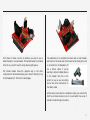
Now you can solder in the battery holder, which is the tallest
part. It’s only 3 pins so you can’t get it in the wrong way around.
The battery you need is of type CR2032 which should last a
number of years in this application. This is a standard type of
coin cell, smaller cells e.g. a CR2020 may fit but will not last as
long or may not deliver enough power to keep the time
accurate.
12
You’ll have to make a choice of whether you want to use a
female header or a male header. The female header is included
in the kit so you don’t need to worry about anything else.
The female header faces the opposite way to the other
components on the board allowing you to insert it directly on top
of the Raspberry Pi. This has it’s advantages.
The alternative is to assemble the board with a male header,
which sits on the same side of the board as the other parts, and
is connected to the Raspberry Pi
via a ribbon cable. If you’re
wanting to attach multiple devices
to the header then this is the
option for you as you can simply
add a few more connections on
the ribbon cable.
A third option could also be considered, where you connect the
HotPi as a female board on top of a board which has a set of
female to male through connectors.
13
Software
Installation
2
To make the HotPi work
you need to install some
software. Depending on
which OS you have chosen
the software may vary in
difficulty.
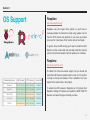
Section 1
OS Support
Raspbian
http://www.raspbian.org/
Raspbian uses the rcsysinit boot system, so you’ll have to
manually activate the hwclock.init script using update-rc.d, but
then the RTC should work perfectly. If you have any trouble
check out the “User Space Tools” section later in the chapter.
To get the fan and LED running you’ll need to install the HotPi
Daemon via the install script and manually install the hotpi.init
script in /etc/init.d and enable it with the update-rc.d command.
Raspbmc
http://www.raspbmc.com/
Operating System
LIRC (kernel)
RTC (kernel)
Fan & LED
Raspbian
Out of the box
Out of the box
Installable
Raspbmc
Out of the box
Out of the box
Installable
OpenELEC
Out of the box
Rebuild Kernel
Installable
ArchLinux
Out of the box
Out of the box
Installable
Pidora
Rebuild Kernel
Out of the box
Installable
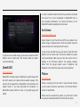
The Real Time Clock has kernel support, but you should still
install the HotPi hwclock upstart scripts in order for it to function
correctly on bootup and shutdown. This is detailed in the “User
Space Tools” section later in the chapter.
To enable the LIRC receiver in Raspbmc go to Programs then
Raspbmc Settings, IR Remote and enable the GPIO TSOP IR
Receiver and select the type of remote you have.
15
In order to enable the Real Time Clock you will have to rebuild
the kernel. This is more complicated on OpenELEC than on
more standard distributions. You should find advice on the
OpenELEC website regarding how to proceed.
ArchLinux
https://www.archlinux.org/
Kernel drivers for both the LIRC and RTC are included in the
default image, configuring these should be possible using the
steps outlined in the “User Space Tools” section.
To get the fan and LED running you’ll need to install the HotPi
Daemon via the install script, that should enable the upstart
script automatically.
OpenELEC
http://openelec.tv/
OpenELEC will likely require rebuilding the system image with
the HotPi daemon and related software added manually. This
process will be supported via OpenELECs documentation and
support forums. If you have performed the installation on
OpenELEC please submit an issue on the github page with
details.
To get the fan and LED running you’ll need to install the HotPi
Daemon via the install script, that should enable the upstart
script automatically. Make sure you have the correct tools for
building on the ArchLinux platform, the package manager
differs from the apt-get system used on Raspbmc and
Raspbian so the instructions may need some adjustment.
Pidora
http://pidora.ca/
Pidora is missing the lirc-rpi driver for using infra-red remotes
so you’ll need to follow the instructions in the “Kernel Drivers”
section to rebuild them.
Pidora uses the rcsysinit boot system, so you’ll have to install
via yum and manually activate the hwclock.init via ntsysv.
16
To get the fan and LED running you’ll need to install the HotPi
Daemon via the install script and manually install the hotpi.init
script in /etc/init.d and enable it with the ntsysv & chkconfig
commands.
If you have any trouble it’s best to speak to the pidora team, but
read through the rest of the manual as there are many bits of
advice that will help you understand the necessary actions
you’ll have to undertake.
17
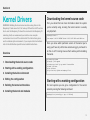
Section 2
Kernel Drivers
WARNING: Building the Linux kernel can take a long time on the
Raspberry Pi and cause the Pi to heat up. Without the HotPi’s active
fan to cool the Raspberry Pi down this can lead to the Raspberry Pi
rebooting itself, we recommend you install a cross compile
environment on a Linux PC as instructed. The instructions given
are for a debian style environment, if you require other instructions
refer to the distribution specific kernel rebuild instructions.
Overview
1. Downloading the kernel source code
2. Starting with a working configuration
Downloading the kernel source code
First you should find out more information about the system
you’re currently using, knowing the kernel version is usually
very important.
raspberrypi$ uname -a
Linux raspbmc 3.10.17 #2 PREEMPT Sat Nov 2 02:51:36 UTC 2013 armv6l GNU/Linux
Once you know which particular version of the kernel you’re
using you’ll have to pull the linux kernel using git, you’ll want to
do this on a PC running Linux as that’s where you’ll be building
the kernel.
pc$ sudo apt-get update
pc$ apt-get -y dist-upgrade
pc$ sudo apt-get install git gcc make bc libncurses5-dev
pc$ mkdir ~/buildroot
pc$ cd ~/buildroot
pc$ git clone http://github.com/raspberrypi/linux
3. Installing the build environment
4. Editing the configuration
Starting with a working configuration
5. Building the kernel and modules
On most systems you can get a configuration for the current
kernel by running the following command
6. Installing the kernel and modules
raspberrypi$ cat /proc/config.gz | gzip -d > DOTconfig
18
You’ll have to copy the file across to the Linux PC, you could
use the scp command to do this or you could access file shares
with samba.
The configuration for the RTC and LIRC features is shown from
menuconfig below
Installing the build environment
You can download the build tools for the Raspberry Pi and
export the prefix for the compiler like so
pc$ cd ~/buildroot
pc$ git clone git://github.com/raspberrypi/tools.git
pc$ export CCPREFIX=$HOME/buildroot/tools/arm-bcm2708/gcc-linaro-arm-linuxgnueabihf-raspbian-x64/bin/arm-linux-gnueabihf-
Editing the configuration
Once you have the existing config from your running distribution
you can copy it into place so the new kernel you’re building will
have the same configuration, except your kernel will include the
RTC_DRV_DS1307 and LIRC_RPI drivers.
pc$ cd ~/buildroot/linux
pc$ cp /path/to/my/DOTconfig .config
pc$ make ARCH=arm CROSS_COMPILE=${CCPREFIX} oldconfig
pc$ make ARCH=arm CROSS_COMPILE=${CCPREFIX} menuconfig
You may get prompted to answer some questions at particular
stages, the default answer to these (press enter) should suffice.
If you’re waiting for a driver release then this might be the time
to pay attention.
19
Installing the kernel and modules
If you want to manually edit the file, then make sure the
following modules and drivers are configured
CONFIG_LIRC=m
CONFIG_IR_LIRC_CODEC=m
CONFIG_LIRC_RPI=m
CONFIG_RTC_LIB=y
CONFIG_RTC_CLASS=y
CONFIG_RTC_HCTOSYS=y
CONFIG_RTC_SYSTOHC=y
CONFIG_RTC_HCTOSYS_DEVICE="rtc0"
CONFIG_RTC_INTF_SYSFS=y
CONFIG_RTC_INTF_PROC=y
CONFIG_RTC_INTF_DEV=y
CONFIG_RTC_DRV_DS1307=m
CONFIG_I2C_BCM2708=m
CONFIG_I2C_BCM2708_BAUDRATE=100000
Installing the kernel means taking the built binaries from your
build system, and transferring them over to the Raspberry Pi.
The easiest way to do this is probably to create an archive of
the binaries with tar, use scp to copy the files over to the
RaspberryPi and untar them. For this example we’re going to
use the IP address 192.168.0.45 for the Raspberry Pi, make
sure that ssh server is running.
pc$ cd ~/buildroot/output
pc$ tar -cvzf mykernel.tgz *
pc$ scp mykernel.tgz [email protected]:/home/pi/
Now on the Raspberry Pi
raspberrypi$ cd /
raspberrypi$ sudo tar -xvzf /home/pi/mykernel.tgz Building the kernel and modules
Building the kernel is done in 2 stages, the kernel image and
then the kernel modules (drivers). Each will be installed to a
location that will make it easy for us to build an archive and put
it on the Raspberry Pi
pc$ make ARCH=arm CROSS_COMPILE=${CCPREFIX}
pc$ mkdir ~/buildroot/output/
pc$ cp arch/arm/boot/Image ~/buildroot/output/boot/kernel.img
pc$ export MODULES_TEMP=$HOME/buildroot/output/
pc$ make ARCH=arm CROSS_COMPILE=${CCPREFIX} INSTALL_MOD_PATH=${MODULES_TEMP} modules_install
Updating the Firmware
It’s a good idea to install new firmware at the same time you
install a new kernel. You should download one of the following
packages, if you’re using 3.10 kernels or newer
https://github.com/raspberrypi/firmware/archive/next.tar.gz
If you’re using a kernel earlier than 3.10 e.g. 3.6
https://github.com/raspberrypi/firmware/archive/master.tar.gz
20
Extract the archive and copy some files to /boot
raspberrypi# tar -xvzf master.tar.gz
raspberrypi# cd firmware-master
raspberrypi# cp boot/bootcode.bin boot/fixup.dat boot/start.elf /boot/
Next remove the /opt/vc folder and replace it with the newer
firmware.
raspberrypi# rm -rf /opt/vc
raspberrypi# cp -a hardfp/opt/* /opt/ # on hard float systems (most)
raspberrypi# cp -a opt/* /opt/ # on software float systems (rare)
Now you should have everything installed for the new kernel.
If you don’t see the rtc_ds1307 and lirc_rpi there’ll probably be
a little mode configuration for your distribution, which is
discussed in more detail in the following chapter.
You can load the modules right now and check that everything
is OK by issuing the following commands
raspberrypi$ sudo modprobe lirc_rpi
raspberrypi$ sudo modprobe rtc-ds1307
If you’re having trouble building or installing a kernel, the best
place to start is the elinux RaspberryPi kernel build guide which
can be found here http://elinux.org/RPi_Kernel_Compilation
Starting up with your new kernel
Reboot the Raspberry Pi and you should boot to your new
kernel.
Once logged in, check which modules are loaded. If everything
is working then you’ll see something like this
raspberrypi$ sudo lsmod
Module Size Used by
bcm2708_wdog 2820 1 uinput 9100 1 lirc_rpi 5216 3 lirc_dev 7036 1 lirc_rpi
i2c_bcm2708 2952 0 rtc_ds1307 5960 0
21
Section 3
User space tools
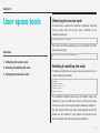
Obtaining the source code
You will need to install some software to download and build
the user space tools. To do this, open a terminal on the
raspberry pi and type
$ sudo apt-get install gcc make git
Overview
Once apt has finished installing you can download the HotPi
source code with git.
git clone http://github.com/klattimer/HotPi.git
1. Obtaining the source code
2. Building & Installing the tools
Building & installing the tools
3. Configuring startup on boot
To build and install the user space tools all you have to do is
run the following commands.
$ cd HotPi
$ chmod +x build.sh
$ chmod +x install.sh
$ sudo ./build.sh
$ sudo ./install.sh
The installation shouldn’t take long and shouldn’t report any
fatal errors. If you do suffer from an error at this point, please
contact us via one of the support options detailed in Chapter 4.
You can test the HotPi’s user space tools using the tools which
should now be installed on your system. You should now be
able to enable the fan with the following commands.
22
$ sudo pifand /var/run/pifan & $ pifan /var/run/pifan 255 # Start the fan service
# Set the fan speed to 100%
Similarly you should be able to use the RGB LED using the
following commands.
$ sudo picolord /var/run/picolor & # Start the LED service
$ sudo picolor /var/run/picolor -i \#FF00FF # Set the color to magenta
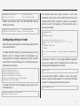
Configuring startup on boot
The HotPi comes with support for /etc/init.d style sysinit and the
newer upstart daemon.
To enable the HotPi for upstart, you should only need to run the
install.sh script. To manually install the hotpi-daemon you
should perform the following commands from within the HotPi
source folder. This will install support for the HotPi daemon and
the hardware clock scripts.
$ sudo cp conf/hotpi /etc/default/
$ sudo cp scripts/hotpi.conf /etc/init/
$ sudo cp scripts/hwclock.conf /etc/init/
$ sudo cp scripts/hwclock-save.conf /etc/init
$ sudo cp scripts/hotpi-daemon.py /usr/bin/hotpi-daemon
$ sudo chmod +x /usr/bin/hotpi-daemon
To enable the HotPi’s init script simply copy the script to the
init.d folder like so.
The default hwclock.init script provided on most linux
distributions should work with the DS1307 Real Time Clock
included with the HotPi, however if it doesn’t it is possible to
add some code to the beginning of the hwclock.init script to
make it more reliable.
/sbin/modprobe i2c-dev
sleep 1
/sbin/modprobe rtc-ds1307
# Get the board revision and pick the correct i2c bus
REVISION=`cat /proc/cpuinfo | grep Revision | cut -d ':' -f 2 | tr -d ' '`
IICBUS=1
if [ $REVISION < "0004"]; then
IICBUS=0
fi
sudo su -c "exec echo ds1307 0x68 > /sys/class/i2c-adapter/i2c-$IICBUS/new_device"
sleep 3
Configuration of LIRC on boot is highly distribution dependent
but you can usually find the configuration files in /etc/lirc/, by
changing /etc/lirc/hardware.conf to include
MODULES="lirc_rpi"
and ensuring that LIRCD is enabled on boot, using either
upstart or sysinit tools like update-rc.d or ntsysv that should be
enough. To manually load the LIRC driver execute
pi# /sbin/modprobe lirc_rpi $ sudo cp scripts/hotpi.init /etc/init.d/hotpi
$ sudo chmod +x /etc/init.d/hotpi
23
Software Guide
3
The HotPi can be
customised in various
ways or instructed to
perform tasks. Here’s how.
Section 1
HotPi Daemon
Adjusting the speed of the fan, indicating
the status of the device using the LED
To change these default patterns you can edit the file /etc/
default/hotpi you can even change the patterns which are
applied under certain states by changing the python code in /
usr/bin/hotpi-daemon which look like this.
self._patterns[LED_PATTERN_OVERHEAT] = [((255,0,0), 100, True), ((0,0,255), 100, True)]
self._patterns[LED_PATTERN_SECURITY] = [((255,30,0), 1000, False), ((255,0,20), 1000, False)]
self._patterns[LED_PATTERN_UPDATES] = [((140,200,0), 1000, False), ((40,100,255), 1000, False)]
self._patterns[LED_PATTERN_OFFLINE] = [((70,140,0), 500, True), ((0,0,0), 500, True)]
The HotPi Daemon is responsible for responding to
temperature rises in the core and increasing the fan speed
accordingly. It is also performing a variety of system tests
including connectivity and update status and indicating
pertinent information or state changes via the RGB LED.
It is also possible to add your own patterns, and it shouldn’t
take a novice python programmer long to identify how to do
this. If you find a great new feature to add, please upstream it
so the rest of us can benefit.
The LED has some default color patterns specified, but these
can be changed to suit whatever you desire, you can also
modify the HotPi daemon to add your own features as the
software is delivered in plain text python!
Setting the fan speeds is configured in more or less the same
way, there are 3 settings of low, medium and high which each
have trigger temperatures. These fan triggers can be changed
in the configuration file located in /etc/default/hotpi
The default configuration for the LED patterns is as follows
At the highest setting the Raspberry Pi’s CPU speed will be
clocked down and the fan will operate at full speed. Achieving
the highest throughput of air for cooling while reducing the heat
dissipation of the CPU. You should never see this happening
with a well ventilated case, and the HotPi is there only to keep
things running smoother in terms of heat management. The
raspberry pi can be programmed with a number of behaviors to
protect it from heat damage, the HotPi is considered more of a
preventative measure.
State
LED Colors
LED Pattern
OK
Magenta
Solid
Network Unavailable
Yellow
Flashing
Updates Available
Yellow/Teal
Pulsing
Security Updates Pending
Orange/Cerise
Alternating
25
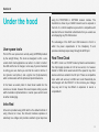
Section 2
Under the hood
User space tools
The HotPi’s user space tools work by using SoftPWM provided
by the wiringPi library. The tools are designed to offer a unix
socket which client applications can write to in order to instruct
the LED and the fan to change in some way. If you’re interested
in writing your own clients you can find the code for both a C
tool (picolor.c and pifan.c) and a python tool (hotpi-daemon)
which communicate with the pifand and picolord daemons.
In the future we would prefer to have these loaded into the
kernel as a module. However this would require writing a pulse
width modulation implementation in kernel space which could
be rather challenging.
using the TSOP1838 or HXT1838 receiver module. The
transmitter is driven by a 2n2222 transistor and is exposed in
the form of a 3.5mm headphone jack which is compatible with
standard infra-red transmitter attachments that you would see
accompanying any PC-USB receiver.
The advantage of the HotPi over USB receivers is that it is
within the power requirements of the Raspberry Pi and
operates extremely responsively through the GPIO port.
Real Time Clock
The RTC circuit is a DS1307 made by Maxim semiconductor,
this chip happily operates at 3.3V at low current, it is however
limited to 100Hz which would also limit the speed of any other
devices which are added to the I2C port. There are compatible
chips which will work up to 400Hz and could theoretically be
interchanged with the DS1307. In this instance your mileage
may vary and it may be difficult or expensive to source a
compatible IC.
Infra-Red
Infra-red is provided using LIRC which is the default method of
using infra-red on Linux, the infra-red hardware operates at
extremely low voltage and provides excellent signal response
26
Section 3
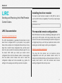
LIRC
Sending and Receiving Infra-Red Remote
Control Codes
Installing the driver module
You have to load the driver module for LIRC_RPI in order to
use the HotPi’s Infra-red capability. This will be a simple single
command.
$ sudo modprobe lirc-rpi
LIRC Documentation
http://www.lirc.org/html/index.html
The LIRC documentation is generally the best place to learn
about how to configure LIRC on your system, in any system
there will be a simple set of configuration files which you’ll very
likely find in /etc/lirc these configuration files, and the kernel
driver lirc_rpi.ko provide the necessary software support to use
the device. With LIRC you install your remote control
configuration files and then software is able to receive signals
from the remote control. Various tools exist to make this
configuration simpler and more accessible (e.g. gnome lirc
settings) to the average user which you are free to explore.
Pre-recorded remote configurations
Most IR Remotes have been painstakingly catalogued over the
years by the LIRC project, with many people doing a small
amount of the work and accumulating the results for everyone it
is highly likely that you will find your particular remote control
already pre-recorded ready to add to your configuration
http://lirc.sourceforge.net/remotes/
You may find that similar, but not identical remote
configurations work with your desired remote control, for
instance most phillips remotes use the same basic controls. It is
usually much easier to start with someone else’s known
working configuration than start your own.
27
Recording Signals
If you’re unable to find an existing configuration for your remote
control you can always record the signals yourself with a simple
tool provided by the LIRC project. You should list out the
buttons and then follow the on screen instructions. Heres how.
IR Transmitters can be found cheaply on ebay or amazon
separately costing between £1 and £3 delivered. They can also
be obtained from MCE remote bundles, and come with some
PCs as part of a remote bundle, so ask around and you might
know someone who has a spare.
$ irrecord --list-namespace
$ irrecord --driver=rpi Testing Signals
To test the signals you need to make sure your new
configuration is properly installed in /etc/lirc/lircd.conf and
you’ve restarted LIRC, it may be easier on some distributions to
simply reboot the device at this point.
$ service lirc restart
$ irw
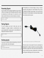
Sending signals
If you plug in a transmitter cable (sold separately) into the HotPi
you’ll also be able to send remote signals.
$ irsend LIST
$ irsend SEND_ONCE TVREMOTE POWER
An LIRC Transmitter cable, taken from an MCE Remote bundle
There have been some reports that when overclocking the
RaspberryPi the software transmitter has worsening reliability
dependent on system load. There have also been reports that
the jack connectors are easy to badly solder. So check these
two things aren’t affecting you first if you have trouble.
28
Section 4
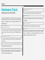
Hardware Clock
$ sudo date -s "01/31/2010 23:59:53"
$ sudo ntp-date ???
Keeping the time when offline
Then you can synchronise the time to the hardware clock
$ sudo hwclock –systohc
To enable the hardware clock you’ll first need to load the i2c
and RTC drivers, this on it’s own may or may not be enough to
initialise the hardware clock, that largely depends on the
operating system.
$ sudo /sbin/modprobe i2c-dev
$ sudo /sbin/modprobe rtc-ds1307
If you want the hardware clock to retain the time as UTC use
this instead
$ sudo hwclock --systohc –utc
To check the time on the hardware clock you can use
$ hwclock -w
You may also need to instruct the i2c bus where the hardware
clock is located. First you need to know which Raspberry Pi you
have.
An upstart script (scripts/hwclock.conf) to initialise the hardware
clock is included in the software distribution and may be
adapted to the specific needs of the user.
$ cat /proc/cpuinfo | grep Revision
For boards earlier than revision 0004 you should specify i2c
bus 0 like so
$ sudo su -c "exec echo ds1307 0x68 > /sys/class/i2c-adapter/i2c-0/new_device"
And all later boards with i2c bus 1
$ sudo su -c "exec echo ds1307 0x68 > /sys/class/i2c-adapter/i2c-1/new_device"
Now you should be able to set the date on the Raspberry Pi, or
if you’re connected update via ntp
29
Support
4
If you’re having trouble
getting the HotPi to work
there are a number of
means for you to get
support.
Section 1
Support
Information
Support External to HotPi
Facebook
Raspberry Pi Foundation & Forums
General support queries can be discussed on our facebook
page, if you need help figuring out which way round something
goes or just general HotPi chit chat. You can find us here
http://raspberrypi.org
https://www.facebook.com/pages/Hotpi/573722212648718
GitHub
For software problems, installation difficulties, distribution
questions, patches and more technical help please use the
issue tracker on Github. If you make changes to the HotPi
software and wish to send those changes to us the best way is
to request a merge on GitHub.
https://github.com/klattimer/HotPi
For general Raspberry Pi, linux or software support questions
you can generally find a lot of information through the following
websites. Each provides it’s own particular support network.
Here you can find all the information on the history and
communities connected to the Raspberry Pi
ELinux Raspberry Pi Hub
http://elinux.org/R-Pi_Hub
Linux Infra-red Remote Control - LIRC
The HotPi uses LIRC for infra-red input and output they have a
website dedicated to debugging problems with LIRC devices.
http://lirc.org
The HotPi specifically uses the lirc_rpi driver which has a home
page here
http://aron.ws/projects/lirc_rpi/
31
Appendix
5
Useful information for
using your RaspberryPi
Section 1
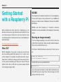
Getting Started
with a Raspberry Pi
We’ve included this section here fore completeness, so an
absolute novice user can get started and use the HotPi from an
out of the box piece of electronics. Your first job will be to pick
an operating system. The best place to look is the Raspberry Pi
downloads page.
http://www.raspberrypi.org/downloads
What OS?
With the Raspberry Pi you need to create your own SD card
with an operating system (OS) loaded on to it in order to boot
up the computer. It is possible to buy SD cards which are preloaded with an OS but it’s always good to know exactly how to
do this yourself. Essentially, you’ll take your choice of OS and
write the entire file to an SD card in a process usually referred
to as “writing an image to disk”.
NOOBS
The Raspberry Pi foundation has built a tool for new Raspberry
Pi users which helps to write an SD card for you. NOOBS will
allow you to install a choice of Raspbian, Pidora and two XBMC
distributions.
NOOBS and other Raspberry Pi foundation endorsed
distributions can be downloaded at the Raspberry Pi downloads
section.
Burning an image manually
To burn an image manually you can use the dd tool at the Linux
or Mac OSX command line. There are slight variations between
the two so be careful which you use.
You’ll have to identify the disk you are using. On Linux you can
do
pc$ dmesg | grep “removable disk”
sd 14:0:0:0: [sdf] Attached SCSI removable disk
On Mac OSX you can use diskutil like this
macos$ diskutil list
Look at the output and check for a disk which matches the size
of the SD Card you’re using. Then to burn the image to an SD
card you will do this on Linux
33
pc$ dd if=~/Downloads/raspbian.img of=/dev/sdf bs=1M
On Mac OSX you’ll do something very similar
macosx$ dd if=~/Downloads/raspbian.img of=/dev/disks3 bs=1M
Other options are available for burning an SD card, and more
information can be found on the Raspberry Pi foundation
website and ELinux Raspberry Pi Hub.
34
Section 2
Raspberry Pi
Hardware
orange serial port (SDA, SCL) and a UART port is available via
the light green (RTS, TXD, RXD).
GPIO Interface
Later models of the Raspberry Pi include a second GPIO
interface which is marked P5 and sits adjacent to P1.
You should keep the current drain less than 50mA for any 3.3V
port which includes all of the GPIO ports. The 5V can drive
more current but you must be careful with using this as a power
source for peripherals.
Figure 5.2 The supplementary P5 GPIO Pinout (top view)
Figure 5.1 The main P1 GPIO Pinout (top view)
There are still some available GPIO pins which aren’t used by
the HotPi board, these are GPIO 4, 8, 14, 15 and 27. The SPI
interface is available via the light blue serial port (MOSI,MISO,
SCLK and CE1). The I2C interface is available via the light
The HotPi doesn’t use the P5 GPIO port but it will obscure it if
installed in a female configuration. However P5 is also too close
to P1 to solder a connector onto the component surface of the
board, it is also “off grid” meaning that the pins do not align
easily with the P1 pin alignment.
This combination of issues mean that if you wish to use the P5
GPIO port it is easier to do so by soldering the header on the
reverse of the board, and thus you would need to horizontally
invert the pin out in figure 5.2.
35
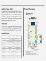
Adding a Reset Button
Physical Dimensions
A hardware reset button is easy and cheap to add to a
Raspberry Pi, using a standard PC Reset Switch available from
any good electronics retailer. It can be installed by soldering a 2
pin header to jumper P6 and connecting the reset switch
directly to those header pins. Any momentary connection
between these pins will hard-reset the board.
Power Test
You can test to ensure the board is getting the correct amount
of power by using a multimeter across test points TP1 and TP2
the voltage measured should be between 4.75 and 5.25 volts.
Specifications
Model A
Model B
CPU
700 MHz ARM11 ARM1176JZF-S core
GPU
Broadcom VideoCore IV,OpenGL ES 2.0,OpenVG
1080p30 H.264 high-profile encode/decode
Memory
128MB
256MB (512MB Rev 3+)
USB
1 via BCM2835
2 via integrated hub
Network
None
RJ45 Ethernet
Storage
Secure Digital|SD / MMC / SDIO card slot
Size
85.0mm x 56.0mm x 15mm
Weight
31g
40g
36
Section 3
Resistor Colour
Chart
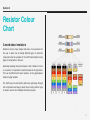
A word about resistors
Resistors come in many shapes and sizes, it is an exercise for
the user to learn how to identify different types of electronic
components but the example of the HotPi demonstrates many
types of components to the user.
Generally speaking there are between 4 and 6 bands of colour
on a resistor. It is important to read the bands in the right order.
This can be difficult with some resistors, as the gap between
bands is highly variable.
The HotPi uses 4 band resistors which are quite large through
hole components and easy to read, this is a fairly common type
of resistor used in most hobbyist electronics projects.
37
Section 4
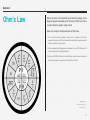
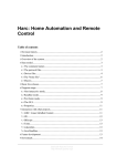
Here are a couple of simple exercises in Ohm’s law.
1. For an LED we need a protector resistor with a voltage of 3.3V and a
required drive current of 20 milli-amps what size Resistor would we need to
have for maximum current output.
2. We’ve measured the Voltage across a Resistor which is 220 Ohms as 4.3V
what is the Current through that Resistor
3. We have 100 RGB LEDs which draw 20mA per colour channel. How much
Power do we require to operate all of the LEDs at 12 Volts.
3.
2.
1.
24 Watts (W)
19.5 milli-amps (mA)
165 Ohms (R)
Ohm’s Law
Ohm’s law is the most important law of electronic design. In the
diagram opposite we display all of the rules of Ohm’s law, this is
a useful reference guide to keep around.
38
Section 5
Getting Started
With Linux
Linux is BIG, really BIG.
Linux is a complete operating system, chances are you’re going
to be using one of the top most popular Raspberry Pi linux
distributions. But event among these, there are variations. I try
to be as general as possible, using raspbian and raspbmc.
Using linux is not something you can jump into head first, so
here I offer some guidance as to what you should try and
familiarise yourself with.
Getting Started
Before you can really do anything with a raspberry pi you’ll
need a terminal, with Raspbian you’ll probably have a local
desktop and be able to launch a terminal from there, otherwise
you can try pressing CTRL+ALT+F1 through F6 to switch to a
command terminal. With Raspbmc you have an opportunity to
switch to the terminal when you exit xbmc, and other
distributions have other similar obvious methods.
Logging In To A Raspberry Pi
If you have a login prompt, usually a combination of username
pi and password raspberry is enough to log in to the system for
the very first time, some distributions may have different log in
parameters so be sure to check the distribution specific
information if you need to.
If you want to log in over the network, you’ll have to learn the
raspberry pi’s ip address and use a terminal on another
computer, for instance putty for windows or “terminal” in Mac
and Linux.
mymacbook$ ssh 192.168.0.54 -l pi
The authenticity of host '192.168.0.54' can't be established.
RSA key fingerprint is 7c:5b:cc:55:62:6c:e4:31:d4:90:4d:2d:d2:e9:a5:62.
Are you sure you want to continue connecting (yes/no)? yes
pi@ 192.168.0.54's password: The programs included with the Debian GNU/Linux system are free software;
the exact distribution terms for each program are described in the
individual files in /usr/share/doc/*/copyright.
Debian GNU/Linux comes with ABSOLUTELY NO WARRANTY, to the extent
permitted by applicable law.
pi@raspbmc:~$
Setting Your Password
Setting the password of the current user
$ passwd
39
Getting Help
Navigating the file system
Any command you execute on a Linux computer should have a
way of getting help for it, the most basic examples would be
something like
Before any user can really get involved with linux they must
understand how to browse the file system structure, with these
tools you will learn how to browse around and make simple
modifications to the file system.
$ ls --help
$ mount -h
more in-depth guides about programming interfaces, as well as
system commands can be accessed in the system manual and
info pages
$ man sprintf
$ info printf
Once you have opened the page you can scroll down using the
arrow keys and quit by pressing ‘q’.
Some things appear in more than one manual page for instance
$ whatis crontab
crontab (1) - maintain crontab files for individual users
crontab (1p) - schedule periodic background work
crontab (5) - tables for driving cron (ISC Cron V4.1)
Using LS To List Directory Structure
Show file size in human readable format
pi@raspberrypi:/var/cache/apt$ ls -lh
total 52M
drwxr-xr-x 3 root root 4.0K Nov 3 12:38 archives
-rw-r--r-- 1 root root 18M Nov 3 12:42 pkgcache.bin
-rw-r--r-- 1 root root 24M Oct 21 19:10 pkgcache.bin.pEcSEd
-rw-r--r-- 1 root root 18M Oct 21 18:53 srcpkgcache.bin
Show files ordered by last modified time
pi@raspberrypi:/var/cache/apt$ ls -ltr
total 52372
-rw-r--r-- 1 root root 17858426 Oct 21 18:53 srcpkgcache.bin
-rw-r--r-- 1 root root 25165824 Oct 21 19:10 pkgcache.bin.pEcSEd
drwxr-xr-x 3 root root 4096 Nov 3 12:38 archives
-rw-r--r-- 1 root root 17903875 Nov 3 12:42 pkgcache.bin
You can access these pages simply by specifying the manual
you want to look at
Using CD To Change Directory
man 5 crontab
Moving around the linux file system can be done with CD,
notice the path changes with each variation. You may also want
to try doing ls after each cd to see what is happening in detail.
40
pi@raspberrypi:/var/cache/apt$ cd /var/log
pi@raspberrypi:/var/log$ cd ../run
pi@raspberrypi:/var/run$ cd ~
pi@raspberrypi:/home/pi$ cd ../../etc
pi@raspberrypi:/etc$ cd ~/Pictures
pi@raspberrypi:/home/pi/Pictures$
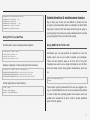
Administration & maintenance basics
Using Find To Locate Files
Day to day use of linux can be difficult to master but has
enough of a documentation base to understand in detail. We’ll
take care of some of the more basic tools that you’re going to
need to get by here, these are rough examples which can help
you get a grasp of how to use the tools quickly.
Find files with a case insensitive wildcard pattern.
Using SUDO & SU To Be ‘root’
$ find /usr/lib/ -iname "liblirc*"
/usr/lib/liblirc_client.so.0
/usr/lib/liblirc_client.la
/usr/lib/liblirc_client.so.0.2.1
Execute commands on files found by the find command
$ find /usr/lib/ -iname "liblirc*" -exec md5sum {} \;
4c3af1b4250154815ad7d1a07327aca8 /usr/lib/liblirc_client.so.0
2f5982e61280033aa997ae7ba3614e98 /usr/lib/liblirc_client.la
4c3af1b4250154815ad7d1a07327aca8 /usr/lib/liblirc_client.so.0.2.1
Sometimes you can only perform an operation as root, the
system super user so you need to elevate your privileges.
There are two common ways to do that, first of all you’ll
frequently use sudo to run a single command as root. At other
times, like when you’re doing system maintenance you’ll use
su.
$ sudo rm /var/log/oldbigfile.log
Password:
Find all empty files in home directory
$ find ~ -empty
/home/pi/.cache/thumbs.db
/home/pi/.config/4575354de3.db
You’ll need to type the password for the user you logged in as,
e.g. pi, most distributions do not set a root password by default
in order to make the operating system more secure, users are
added to the sudoers file in /etc in order to access protected
parts of the file system.
41
By switching user using su, you effectively become the super
user until you type exit
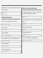
Setting File Permissions And Ownership
pi@raspberrypi:~$ sudo su
Password:
root@raspberrypi:/home/pi#
To change the permissions on a file you can use the chmod
tool, for instance, making the file executable.
Copy, Move And Delete Files
Copy a script into a global search path for executing
$ sudo cp myscript.sh /usr/local/bin/
Create a new folder
$ sudo mkdir /etc/myscript/
Create a nested folder
$ sudo mkdir -p /var/log/myscript/deguglog
Move a configuration file into the system configuration folder
$ sudo mv myscriptconfig /etc/myscript/
$ chmod +x file.sh
Give full permissions to the file, user and group read/write/
execute.
$ chmod ug+rwx file
Making the file group read/write
$ chmod g+rw file
Changing ownership of a file
$ sudo chown root.root file
You can do this recursively to a folder by adding -R
$ sudo chown -R root.root /mnt/disk/folder
Remove an old dead file
$ rm /home/pi/.cache/thumbs.db
Recursively removing a folder
rm -rf /var/lib/cache/oldcache
42
Using Mounted Filesystems
Checking a file system for errors
$ sudo fsck /dev/sdb1
Overview of mounted filesystems
$ df -h
If you want to show the file system type you can try
$ df -hT
Mounting an external disk, after you mount or unmount a disk,
take a look at what changed using df.
Processes And Memory
Check all running processes, showing user and other useful
information
$ ps -aufx Check the system memory utilisation
$ sudo mount /dev/sdb1 /mnt/USBHDD
$ free
Mounting a disk image
Show the real time process monitor
$ sudo mount /image.img /mnt/IMAGE -o loop
$ top
Remounting root filesystem as read-only
Get the process ID of a named process
$ sudo mount / -o remount,ro
$ pidof pifand
Remounting root filesystem as read-write
Kill a process by pid
$ sudo mount / -o remount,rw
$ sudo kill -9 553
Unmounting an external disk
Combining the two commands into one
$ sudo umount /mnt/USBHDD
$ sudo kill -9 `pidof pifand`
43
Archive Tools
Compress a file with bzip2, the file will have .bz2 appended to
its name
$ bzip2 file
Unzipping a zip file
$ sudo apt-get install unzip
$ unzip -e zipfile.zip
Unraring a rar file
$ sudo apt-get install unrar
$ unrar -x rarfile.rar
Uncompress a file, bz2 extension will be removed
$ bzip2 -d file.bz2
Manipulating And Searching Text Files
Uncompressing with gzip, gz extension will be removed
$ gzip -d file.gz
Search a file for a phrase
grep -l search-phrase file.txt
Compressing with gzip, the file will have .gz appended to its
name
Search for a phrase recursively
$ gzip file
grep -Rl search-phrase /path/
Create a tarball archive, with gzip compression
Print the case-insensitively matched line, along with the three
following lines
$ tar -cvzf tarball.tar.gz Path/*
$ grep -A 3 -i "search-phrase" file.txt
Unarchiving a tarball which is compressed with gzip
$ tar -xvzf tarball.tar.gz
Print a file to the screen
$ cat file
Unarchiving a tarball which is compressed with bzip2
$ tar -xvjf tarbzip.tar.bz2
Print the differences between files (unified diff)
$ diff -uNr a.txt b.txt
44
Print the last few lines of a file
$ tail /var/log/dmesg
Follow a file as it’s being printed to
$ tail -f /var/log/dmesg
You can navigate through the file using the arrow keys, and
type text when you enter insert mode by pressing the insert key
or the i key
Go to the 47th line of file, or when you have a file open, press
escape, then type the number of lines to jump followed by down
Append a file on to another
$ vim +47 longfile.txt
$ cat additions >> outfile
Go to the first match of the specified
Overwrite the contents of a file with the contents of another
$ vim +/searchphrase textfile.txt
$ cat newdata.txt > data.txt
Replacing a phrase inside a file
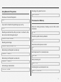
Basic Networking Tools
sed -i 's/old text/new text/g' file.txt
View active network connections and their status
Replacing a phrase recursively with find
$ ifconfig -a
$ find /path/to/files/ -type f -exec sed -i 's/old text/new text/g' {} \;
Bring up the first ethernet device
Open a file with vim
$ sudo ifup eth0
$ vim file.txt
Take down the first ethernet device
Open the file read only.
$ sudo ifdown eth0
$ vim -R file.txt
Test connectivity between your computer and your local router
To quit the file type
$ ping 192.168.0.1
<ESC>:q
45
Test connectivity with the wider world
Updating The System
$ ping 8.8.8.8
Update the directory of software sources
Test to see if a port is open on the local system
$ sudo apt-get update
$ telnet localhost 22
Initiate an upgrade of the system
Downloading a file over http or ftp
$ sudo apt-get upgrade
$ wget http://downloads.raspberrypi.org/NOOBS_latest -O NOOBS_v1_3_2.zip
Installing Software
On rasbpian and possibly other distributions, there is a tool for
configuring certain aspects of the system.
$ sudo rpi-update
Installing software, and of course removing software is done
using apt-get, for instance to install gcc and python you would
use
$ apt-get install gcc python To remove a package
$ apt-get remove gcc
To search for packages
$ apt-cache search python sdl
46
Section 6
User Photos
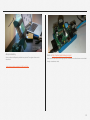
Karl Lattimer
Here’s one of my own boards mounted
onto the back of a TV Bracket. Even
though the sensor points upwards the infra
red remote is still very reliable.
Dave Painter
17 July 1981 - 7 May 2013
An avid Supporter of the HotPi who
provided excellent publicity and
marketing support to the kickstarter
effort, a good friend who will be
missed.
47
Benjamin Bellamy
Here’s a video that Benjamin published on youtube. The original video can be
found here
Frank at http://raspberryalphaomega.org.uk/
Here’s a HotPi board built with through pins on the header so another device can be added
through an extension cable.
https://www.youtube.com/watch?v=SGCmprXYDzw.
48