1
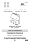
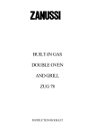
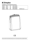
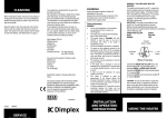
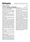
FIRECHARM R.S. Electronic
Room Sealed Live Fuel Effect Gas Fire
G.C. No. 32 689 43 (BLACK)
G.C. No. 32 689 44 (BRONZE)
Users Operating Instructions
The FIRECHARM R.S. Electronic is a room sealed, live fuel effect gas fire with coals. The outer case is available in two colours,
antique bronze or black.
It has a balanced flue system which takes air for combustion from the outside and discharges products of combustion to the
outside. It must be mounted on an external wall and can stand on a non-combustible hearth or suitable fire surround. There are
four heat settings operated by turning the control knob which is located at the top right hand side of the fire. The burner system
is designed to give various flame effects at the respective heat settings.
Ignition is by battery spark generator operated by turning and pressing the knob to light the pilot. It has a thermo electric flame
supervision device for safety. Use only the coal bed supplied with this fire. Do not use any other material or burn any rubbish on
the fire. Do not use the fire with a broken or damaged fuel bed or with a broken or cracked glass.
IMPORTANT NOTES
1.
2.
3.
4.
5.
6.
7.
This fire is for use on Natural Gas only and cannot be used on any other gas (G20 at 20mbar).
The fire must be installed and serviced regularly in accordance with the installation/servicing instructions, the rules in
force and Gas Safety (Installation and Use) Regulations, by a competent person, i.e. a Gas Safe registered Engineer.
The glass door becomes very hot when the fire is in use and must not be touched. The glass door conforms with the
requirements of BS 1945 : 1991 and satisfies the Heating Appliances (Fireguards) (Safety) Regulations 1991. The door is to
prevent risk of fire or injury from burns and it shall not be permanently removed or the fire used without it fitted.
IT DOES NOT GIVE FULL PROTECTION FOR YOUNG CHILDREN, THE ELDERLY OR THE INFIRM .
A fireguard conforming to B.S. 8423 (Fireguards for heating appliances for domestic use) should be used for the protection
of children, the elderly or the infirm. Such a guard is also recommended for pet animals.
WARNING: The glass is of a special heat resisting type, and if damaged must be replaced with the proper spare.
A minimum clearance of 500mm is required to a combustible adjacent wall.
After the fire has been installed you may wish to fix a shelf of combustible material above. This is quite acceptable provided
the dimensions shown in the table below are used. For deeper shelves allow 15mm (5/8in) increase in shelf clearance for
every 25mm (1in) additional shelf depth.
Minimum Height to
Depth of Shelf
On the outside wall, the flue terminal (and terminal guard if fitted) must be clear of
Underside of Shelf
obstructions (as for wall heaters).
mm
in
mm
in
The distance between the sides of the fire and any permanent fittings must be at
125
5
130
5
1/8
least 75mm (3in). This permits proper access to the case fixing screws, and to
150
6
145
53/4
change the battery.
175
FOR USE IN G.B. & I.E.
1
7
160
63/8
USER
8.
Clothes etc. must not be draped over the fire. Curtains must be 150mm (6in) clear at the top of the heater and 50mm (2in)
at the sides. If wall mounted do not obstruct the underside of the fire.
9.
"Soft furnishings" such as blown vinyl wallpaper are easily affected by heat and may become discoloured if fitted close to a
heating appliance. Please bear this in mind when installing a heater/fire and when decorating.
10. When the fire is first used a slight smell may be given off but this will soon clear. Condensation on the window inner surface
is normal, when the heater is lit from cold.
11. This product uses fuel effect pieces containing Refractory Ceramic Fibre (RCF), which are man-made vitreous silicate
fibres. Excessive exposure to these materials may cause temporary irritation to eyes, skin and respiratory tract,
consequently, it makes sense to take care when handling these articles to ensure that the release of dust is kept to a
minimum.
TO LIGHT AND OPERATE
The control knob is located on the top right hand side of the fire and
is shown in Fig. 1A. The ignition spark generator, battery powered
(size AA), is located at the lower rear RH side.
WARNING: If the pilot light is extinguished either intentionally or
unintentionally, no attempt should be made to relight the gas until at
least three minutes have elapsed.
2
HIG
H
TO LIGHT THE FIRE: Turn the control knob anticlockwise to the
(pilot) position. Depress the control knob, sparks will be heard and
the pilot should light, this can be confirmed by looking through the
glass to the right hand side of the fuel bed in the direction of arrow
‘A’ (See Fig 1B). If the pilot is lit, hold down the control knob for a
further 10 seconds before releasing. The pilot should remain alight. If
the pilot does not remain alight, or has not ignited, push in the
control knob slightly, turn back to OFF and repeat the above
procedure.
Turn the control knob to setting 1 before choosing any other.
NOTE: The control knob should be pushed in slightly before
turning, and always set to one of the stated positions.
It is connected to the gas tap by a universal coupling and will have a
‘loose feel’ to it, which should not cause concern.
1
OFF
PILOT
Fig. 1A
TO TURN OFF: Push in the control knob slightly and turn it clockwise to OFF position.
WARNING: If you want to relight a hot fire wait three minutes before doing so.
A
Fig. 1B
2
EC
ON
A
HEAT SETTINGS
There are four heat settings 1, HIGH, 2 and ECON (See Fig. 1A). Setting 1 provides gas to the full burner at a low level. Setting
HIGH gives the full heat output. Setting 2 uses about the same amount of gas as 1 but limits this to the centre section of the
burner. You therefore see a different flame picture but still see the pilot flame on the right. Setting ECON is the lowest heat
setting and gives gas at a low rate to the centre burner section. Never turn the knob quickly from pilot to 2 or ECON, always
turn to 1 first.
CLEANING
(SEE COAL BED)
NOTE: Abrasive cleaners should never be used.
All cleaning should be carried out when the fire is cold. As the fire is used, the bright metal finish around the fuel bed will darken
to enhance the fuel effect. There is no need to use metal polish on these parts as the discoloration is normal. Generally the fire
would only need dusting. Any painted surface or metal part may be cleaned with a damp cloth. Any stains on the glass can be
remove with a non-abrasive cleaner or ceramic hob cleaner. The fuel effect components may be cleaned with a soft brush. It is
recommended that a vacuum cleaner is not used.
TO REMOVE THE GLASS DOOR
Pull the door mask upwards and forwards (see fig 1B). The glass door is retained by ten wing nuts and after removing these
you may slide the glass door forwards and away from the fire. The inside of the window should be cleaned with a ‘ceramic hob’
cleaner, such as Hobbrite, before refitting
COAL BED
The coal bed is a one piece assembly and may be removed for cleaning or exchanging. To do this first remove the glass door
as previously instructed then lift the coal bed straight out. Take care as the coal bed is a fragile component. When replacing
ensure that the end cut out of the coal bed is positioned over the pilot on the right hand side of the fire. (See Fig. 2).
Should any soot accumulation become excessive, the fuel effect pieces should be removed from the fire for cleaning. Cleaning
should be carried out in a well-ventilated area or in the open air, by gently brushing with the pieces held away from your face so
that you avoid inhaling the dust. We do not recommend the use of a normal domestic vacuum cleaner, which may blow dust back
into the air.
Fig. 2
3
CHANGING THE BATTERY
The ignition spark generator, containing the battery (size AA), is located at the lower rear RH side. Unscrew the cap, anticlockwise, off the battery holder. Remove the battery, and replace with a new one. This should be inserted ‘flat end first’ - this is
the negative terminal. Replace the cap carefully to avoid cross-threading it.
Please note: Consumable items, such as batteries, are not covered by the guarantee.
SPARES AND SERVICE
For spares and service apply to your local supplier or installer stating that the appliance is a FIRECHARM R.S. Electronic. The
appliance G.C. Number is 32 689 43/44 and this together with the serial number of the fire is shown on the small label on the
lower right side of the fire.
Advantage should be taken of annual servicing/inspection by a Gas Safe registered Engineer, to ensure continued safe and
efficient operation of the fire. For case parts always say whether your fire is bronze or black.
Full on the fire consumes 4.5 units of gas per hour. The cost of a unit of gas varies according to the tariff. Please check with
your local Gas Region. Based on the cost of gas at 2.5 pence per kW hour at the High setting 4.5kW costs 11.3 pence per hour
approximately, and at Econ setting using 1.5kW costs 3.8 pence per hour approximately. The maximum output is 3.57kW, and
the minimum output is 1kW.
THE GAS CONSUMERS' COUNCIL
(GCC) IS AN INDEPENDENT
ORGANISATION WHICH PROTECTS
THE INTEREST OF GAS USERS.
IF YOU NEED ADVICE, YOU WILL FIND
THE TELEPHONE NUMBER IN YOUR
LOCAL TELEPHONE DIRECTORY
UNDER GAS.
Robinson Willey part of GDC Group Ltd
Millbrook House, Grange Drive, Hedge End, Southampton, SO30 2DF
Telephone: 0844 879 3588 Fax: 0844 879 3582
Website: www.robinsonwilley.co.uk
Email: [email protected]
Robinson Willey is a Trading Division of the GDC Group Ltd
4
987615
Issue 4