1
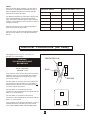
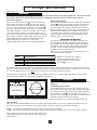
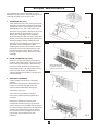
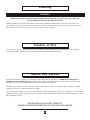
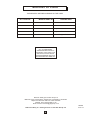
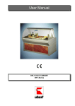
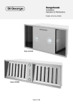
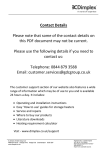
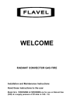
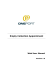
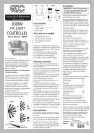
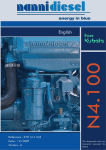
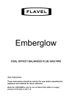
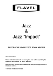
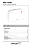
SAHARA with Safeguard and SAHARA DE LUXE with Safeguard
USER'S INSTRUCTIONS
IMPORTANT - This fire is for use on Natural Gas ONLY (G20)
INTRODUCTION
Sahara
This fire must be installed and serviced by a ‘Gas Safe’
registered engineer in accordance with the Installation and
Servicing Instructions, Gas Safety (Installation and Use)
Regulations and the rules in force.
Where solid fuel has been used, the chimney must be
swept prior to installation.
IMPORTANT: "SOFT FURNISHINGS"
When considering fitting any heating appliance or
wallpapering a room in which one is fitted, if "soft
furnishings" or other heat sensitive materials are used in the
vicinity of the heat source, they may become heat
damaged or discoloured.
DRESSGUARD: The guard on this appliance conforms to
the requirements of BS 1945 : 1991 and satisfies the
Heating Appliances (Fireguards) (Safety) Regulations 1991.
The guard is to prevent risk of fire or injury from burns and
should not be permanently removed.
IT DOES NOT GIVE FULL PROTECTION FOR YOUNG
CHILDREN, THE ELDERLY OR THE INFIRM. A fireguard
conforming to B.S. 8423 (Fireguards for heating appliances
for domestic use) should be used for the protection of
children, the elderly or the infirm. Such a guard is also
recommended for pet animals.
Sahara De Luxe
THIS LEAFLET IS INTENDED TO HELP YOU
UNDERSTAND AND USE YOUR NEW GAS FIRE
EFFICIENTLY. PLEASE READ THESE
INSTRUCTIONS
BEFORE USING THE FIRE AND KEEP FOR FUTURE
REFERENCE.
RADIANT/CONVECTOR
GAS FIRE
Sahara (Pewter)
G.C. No. 32 689 38
Sahara (Antique Bronze)
G.C. No. 32 689 39
Sahara De Luxe (Pewter)
G.C. No. 32 689 40
Sahara De Luxe (Antique Bronze) G.C. No. 32 689 41
LEAVE THESE INSTRUCTIONS WITH THE USER
1
USER
NOTE:
After the fire has been installed, you may wish to
fix a shelf of combustible material above. This is
quite acceptable provided you comply with the
dimensions shown in the table.
The distance between the case side of the fire and
any permanent fittings must be at least 50mm
(2in). The battery powered ignition option requires
around 115mm clearance at the RH side in order to
change the battery.
When the fire is first used, a slight smell may be
given off, but this will soon clear.
HEIGHT OF SHELF (above fire)
DEPTH OF SHELF
mm
(in)
mm
(in)
152
6
115
4½
165
6½
122
4¾
178
7
128
5
191
7½
135
5¼
201
8
141
5½
On the De Luxe model some light will be reflected
below onto the hearth, and onto the wall behind
the fire.
Electrical Connections (De Luxe)
This appliance must only be connected to a
200/250 v.a.c. 50Hz supply.
GREEN AND YELLOW - EARTH
BLUE - NEUTRAL
BROWN - LIVE
GREEN/YELLOW
E
3A FUSE
WARNING
THIS APPLIANCE MUST
BE EARTHED
BLUE
N
As the colours of the wires in the mains lead of this
appliance may not correspond with the coloured
markings identifying the terminals in your plug,
proceed as follows:
L
BROWN
The wire which is coloured green and yellow must
be connected to the terminal in the plug which is
marked with the letter E or by the earth symbol
or coloured green and yellow.
The wire which is coloured blue must be
connected to the terminal which is marked with the
letter N, or coloured black.
E
The wire which is coloured brown must be
connected to the terminal which is marked with the
letter L, or coloured red.
N
If the terminals of the plug are unmarked, consult a
qualified electrician. Two pin plugs must not be
used. FOR FUSED PLUGS, USE A 3 AMP FUSE.
L
Fig. 1
2
To Light and Operate
(Refer to Fig. 2)
WARNING
If the flames are found to be extinguished and the control knob is NOT in the OFF position, the control knob must
be turned to OFF and no attempt should be made to relight the gas until at least 3 minutes have elapsed.
Piezo Spark Ignition
Push in the control knob and turn it anti-clockwise from
OFF position towards the pilot
position until you feel
some resistance. With the knob still pushed in, pause for
one to two seconds and then continue to turn to pilot .
The piezo operates and two ‘clicks’ will be heard and the
pilot lights. Keep the control knob pushed in for a further
10 seconds before releasing. The pilot should remain lit
and can be seen below the right centre radiant. If the pilot
did not light or failed to remain alight, push in the control
knob slightly and turn clockwise to OFF position and
repeat the lighting procedure. Once the pilot is
established turn the control knob to the desired setting.
Battery Spark ignition
Depress the control knob and turn it slowly anticlockwise to
the pilot position. Depress the control knob, sparks will
be heard and the pilot should light which can be seen
below the right centre radiant. If the pilot did not light try
again, by depressing the control knob. When the pilot has
lit keep the knob depressed for a further 10 seconds to
activate the flame supervision device, otherwise the pilot
will go out again. Once the pilot is established turn the
control knob to the desired setting.
CHANGING THE BATTERY
The ignition spark generator, containing the battery (size
AA), is located at the lower rear RH side. Unscrew the cap,
anti-clockwise, off the battery holder. Remove the battery,
and replace with a new one. This should be inserted ‘flat
end first’ - this is the negative terminal. Replace the cap
carefully to avoid cross-threading it.
Please note: Consumable items, such as batteries, are
not covered by the guarantee.
Control Knob
Setting
Radiant Picture
1
Centre 2 radiants on low
2
Centre 2 radiants on full on
3
Centre 2 radiants on full on,outer 2 on low
4
All 4 radiants on full on
NOTE: The control knob is situated
on the top right hand side of the
fire and is marked with the symbols
OFF, Pilot , 1, 2, 3, 4.
The fire is fitted with a flame supervision and Oxygen depletion device. This will shut the fire off if the pilot goes out for
any reason. This may be caused by the Oxygen level in the room falling below a prescribed level due to a poor flue pull
etc. If the fire keeps going out you must have it checked by a ‘Gas Safe’ registered engineer.
The pilot burns at all settings, giving a localised extra glow to the left of the centre right hand radiant. This localised
glow will be more visible at the lower settings, and is quite normal.
WARNING
PILOT
If you want to relight a hot fire, wait 3 minutes before
doing so.
LIGHTING WITH A TAPER
In the unlikely event of failure of the ignition spark, the
fire can be lit with a taper. First light the taper and apply
it to the pilot and then press the control knob and turn it
anti-clockwise to pilot position. After the pilot is lit,
keep the knob pushed in for a further 10 seconds before
releasing. The pilot should still remain lit.
1
SAHARA
WITH
OFF
2
SAFEGUARD
LIFT
3
4
Fig. 2
A control knob adaptor to assist the operation of the fire is included if required. If not, keep it for possible future use.
TO TURN OFF
Push in the control knob slightly and turn it clockwise to the OFF position. If you wish, instead of turning to OFF you
may turn to PILOT and leave the pilot running permanently. The pilot consumes very little gas (0.2kW).
NOTE 1: Instructions for lighting are also in the lift up lid of the bezel on the fire.
NOTE 2: The control knob should be pushed in slightly before turning and always set to one of the stated positions.
The control knob is connected to the gas tap by a universal
coupling and will have a ‘loose feel’ to it, which should not
cause concern.
3
Simple Maintenance
Do not attempt to clean the fire while it is warm.
Withdraw the plug from the electricity supply before
removing any parts of the fire (De Luxe).
1. SPINNERS (De Luxe)
If the spinners do not rotate, remove the fender
assembly by first lifting it upwards and pulling
it away from the fire, remove the log effect and
lift the spinners out. (N.B.: Take care as the
pivot pins are very sharp). Observe if any of the
spinner blades are distorted and, if so, set
these to the same angle as the remainder.
Check that the pivot pins are clean, sharp and
vertical. If necessary lubricate the spinner pivot
bearing by lightly rotating a sharpened soft
lead pencil in the bearing in the underside of
the plastic centre of the spinner. When
replacing the spinners, fit the spinner with the
red plastic centre on the right hand pin, and
the spinner with the white centre on the left
hand pin. Replace the log. Replace the fender
assembly.
Fig. 3
2. BULB CHANGING (De Luxe)
Remove the fender assembly by first lifting it
upwards and pulling it away from the fire, then
remove the log and spinners. The bulbs may
be removed and replaced as required using
60W Fireglow bulbs. The maker's part number
is 820 134 and the G.C. Part Number is
138 076. Replace the spinners, log effect and
fender assembly.
When replacing the
log these "log ends"
must be at the bottom.
Fig. 4
3. RADIANT CHANGING
Caution: Make sure the fire is cold before
starting.
Remove the dressguard by withdrawing the
prongs from the left and right hand side
reflectors then withdraw the dressguard
downwards (See Fig. 5).
Take care not to scratch the reflectors.
Remove the radiant by lifting upwards and
outwards.
Replace the radiants by inserting them
underneath the firebox canopy top first and
ensure that they sit down behind the front lip of
the radiant support. Replace the dressguard by
inserting the vertical prongs into the holes in
the top reflector then re-engage the left and
right prongs into the holes in the side
reflectors.
Fig. 5
4
Cleaning
WARNING
Withdraw the plug from the electricity supply before cleaning any parts of the fire ( De Luxe)
Do not attempt to clean the fire while it is warm.
Generally cleaning can be done with a damp, soapy cloth, followed by polishing with a soft cloth. if necessary, the
chromed parts only may be cleaned with a metal polish. Abrasive cleaners should never be used. The radiants can be
dusted with a soft brush. Do not polish the canopy, a light dusting is sufficient.
Transfer of Fire
If for any reason the user wishes to have the gas fire fitted to another fireplace, the closure plate, i.e. the metal plate
covering the fireplace opening must be taken with the fire for installation at the new site.
Spares and Service
For spares and service, apply to your local British Gas stating that the appliance is a SAHARA with Safeguard or
SAHARA De Luxe with Safeguard and quote the G.C. Number and Serial Number which can be found on the right
hand side of the fire. You must also state if your fire has battery spark ignition.
Full ON this gas fire will consume 6.04 units of gas per hour and 1.55 units on low setting. When installed in a typical
chimney, the fire gives a maximum output of 4.78kW.
If any "Home Improvements" are made to the dwelling in which a gas appliance is fitted, e.g. the fitting of an extractor fan,
draught-proofing or double glazing, then the air supply to and the flueing of the appliance must be re-checked by a ‘Gas
Safe’ registered engineer.
ADVANTAGE SHOULD BE TAKEN OF
ANNUAL SERVICING/INSPECTION FOR GAS APPLIANCES
5
Shortlist of Parts
THESE PARTS ARE REPLACEABLE BY THE USER.
G.C. PART No.
MAKERS PART No.
DESCRIPTION
154 371
995971
Radiant
138 913
820863
Control Knob
159 505
822161
Spinner L.H. White Centre
159 504
822160
Spinner R.H. Red Centre
138 076
820134
60W Fireglow Bulb
THE GAS CONSUMERS' COUNCIL
(GCC) IS AN INDEPENDENT
ORGANISATION WHICH PROTECTS
THE INTEREST OF GAS USERS. IF YOU
NEED ADVICE, YOU WILL FIND THE
TELEPHONE NUMBER IN YOUR LOCAL
TELEPHONE DIRECTORY UNDER GAS.
Robinson Willey part of GDC Group Ltd
Millbrook House, Grange Drive, Hedge End, Southampton, SO30 2DF
Telephone: 0844 879 3588 Fax: 0844 879 3582
Website: www.robinsonwilley.co.uk
Email: [email protected]
Robinson Willey is a Trading Division of the GDC Group Ltd
6
992490
Issue 12