1
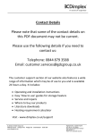
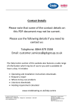
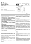
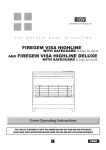
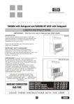
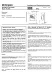
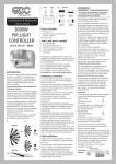
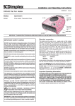
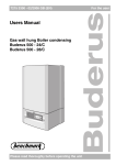
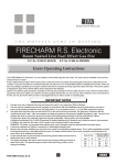
 Contact Details Please note that some of the contact details on this PDF document may not be current. Please use the following details if you need to contact us: Telephone: 0844 879 3588 Email: [email protected] The customer support section of our website also features a wide range of information which may be of use to you and is available 24 hours a day. It includes: • Operating and installation instructions • Easy ‘How to use’ guides for storage heaters • Service and repairs • Where to buy our products • Literature downloads • Heating requirement calculator Visit ‐ www.dimplex.co.uk/support A division of GDC Group Ltd
Millbrook House Grange Drive Hedge End Southampton SO30 2DF
www.dimplex.co.uk
Registered No: 1313016 England
VAT GB 287 1315 50004
EEE Producer Registration Number –
WEE/GE0057TS
Paper from sustainable sources
Installation and Operating Instructions
Downflow Fan Heater
Model : FX 20VE
08/30042/6
Issue 6
(IP22)
ceiling
Dimensions
250
MIN
(millimetres)
Model
Specification
FX 20VE
(High level) 1or 2kW + Electronic, run-back timer
229
109
300
MIN
242
600
MIN
1800
MIN
shelf
floor
Fig. 1
THESE INSTRUCTIONS SHOULD BE READ CAREFULLY AND RETAINED FOR FUTURE REFERENCE
IMPORTANT SAFETY ADVICE
WARNING - DO NOT USE THIS HEATER IN THE IMMEDIATE
SURROUNDINGS OF A BATH, A SHOWER OR A SWIMMING POOL.
DO NOT COVER THE APPLIANCE or place material or
garments on it, or obstruct the air circulation around this
appliance, for example with curtains or furniture, as this
could cause overheating and a fire risk.
DO NOT PLACE AEROSOLS OR OTHER CONTAINERS
SUSCEPTIBLE TO HEAT IN THE DIRECT AIRFLOW FROM THE
UNIT.
WARNING - Do not operate the heater with the top cover
removed. This will trip the thermal fuselink.
THIS HEATER MUST NOT BE LOCATED IMMEDIATELY BELOW
A FIXED SOCKET OUTLET.
The appliance is not intended for use by children or other
persons without assistance or supervision if their physical,
sensory or mental capabilities prevent them from using it
safely. Children should be supervised to ensure that they
do not play with the appliance.
WARNING – DISCONNECT THE HEATER FROM THE ELECTRICITY
SUPPLY BEFORE UNDERTAKING SERVICE OR REPAIR.
WARNING – If the appliance is fitted in a bathroom, a cable
outlet will be necessary with the supply to the unit
controlled by a double pole switch. The switch if inside
the bathroom should be pull cord operated and if outside
should be adjacent to the entrance door. The appliance
must be mounted so that no part of it can be touched by
any person using bath or shower.
THIS HEATER MUST NOT BE OPERATED WITHOUT THE COVER
CORRECTLY IN POSITION.
Warning - In order to avoid a hazard due to inadvertent
resetting of the thermal cutout, this appliance must not be
supplied through an external switching device, such as a
timer, or connected to a circuit that is regularly switched
on and off by the utility.
General
The heater has a loading of 2kW. It is designed for permanent wall
mounting and is suitable for operation on A.C. electricity supply having
the same voltage as shown on the rating label.
The heater is fitted with an internally mounted selector switch which on
installation of the heater allows a choice of 1kW or 2kW output to suit the
dimensions of the room to be heated.
In rooms of less than 9 – 11 cubic m. (350 - 400 cubic ft.) 1kW output
should be selected, otherwise nuisance tripping of the thermal overload
cut-out may occur.
NOTE : THE SWITCH HAS BEEN FACTORY SET FOR 1kW OPERATION.
IF ADDITIONAL OUTPUT IS REQUIRED, 2kW CAN BE SELECTED ON
INSTALLATION.
SUPPLY CABLE IS NOT SUPPLIED WITH THIS APPLIANCE AND IT
SHOULD THEREFORE BE INSTALLED BY A COMPETENT ELECTRICIAN
IN ACCORDANCE WITH THE LATEST IEE REGULATIONS.
Safety
Cut-Out
For your safety, this appliance is fitted with a thermal cut-out. In the
event that the product overheats, the cut-out switches the heater off
automatically.
To bring the heater back into operation, remove the cause of overheating,
then turn off the electrical supply to the heater for a few minutes.
When the heater has cooled sufficiently reconnect and switch on the
heater.
Fuse Link
A thermal fuse link is provided as an added safety feature. If the fuse link
operates and opens circuit it is the result of abnormal overheating within
the appliance.
To ensure the future safe operation of the heater please contact Dimplex
Customer Services.
Installation
WARNING: Minimum clearences must be adhered to when mounting
the heater.
Before undertaking installation work, ensure the electricity supply is
disconnected from any relevant fixed wiring. Supply cable is not supplied
with this appliance and it should therefore be installed by a competent
electrician in accordance with the latest IEE wiring regulations.
The supply circuit must be adequate for the input of the appliance and
must be protected with a 13A fuse.
A suitable termination to the fixed wiring of the premises must be provided
adjacent to the final position of the appliance through a double pole
switch having a contact separation of at least 3mm in all poles.
Installation Procedure
It is essential to observe minimum wall mounting clearances - see Fig. 1.
The appliance should be fitted horizontally, with the cable entry at the top
and grille at the bottom. It must be mounted not less than 1800mm above
the floor with a clearance of at least 600mm to any shelf or projecting
surface below the heater and not less than 300mm below the ceiling or
other projecting surface. It must also be not less than 250mm from an
adjacent projecting surface. For most effective heating performance
the heater should be mounted at the minimum height : i.e. 1800mm above
the floor.
Care must be taken to ensure that when in use, the air stream is not
obstructed by a high shelf or cabinet.
The appliance is secured to the wall with three screws, two through
keyhole slots and one through a centrally positioned lower hole to hold
the appliance firmly in position (see Fig. 2).
116
22
2 No.
Keyhole
Slots
Mains Cable
Cable entry
72
116
95
Hole for
3rd Screw
L
N
Terminal
Block
Exploded view of
Terminal Block
Fig. 2
C
L
1.
2.
3.
4.
5.
6.
7.
8.
9.
Remove the top cover from the appliance by removing the two
screws securing the top cover and hinging it back.
Mark the position of the keyhole slots on the wall and drill and plug
for the two suitable screws.
Partially insert the two screws, then hang the appliance on these
screws and mark the position of the lower centrally positioned
screw.
Remove the appliance and drill and plug for the third screw.
Remount the appliance on the wall, ensure that it is horizontal and
fix in position by tightening all three screws.
Feed the supply cord or wires through the inlet at the top rear of
the appliance leaving sufficient free length to connect to the terminal
block.
Make electrical connections to the terminal block ensuring that the
live connection is made to the terminal marked ‘L’ and the neutral
connection to the terminal marked ‘N’ (see Fig. 2 exploded view).
Operate the selector switch to provide either 1kW or 2kW output.
Replace the top cover and screws.
The appliance is now ready for use and the electricity supply can be
reinstated.
This model has a run-back timer
which can be set on a run time of 5
– 155 minutes. This can be adjusted
by removing the top cover and
moving the jumpers on the timer, e.g.
to run the timer for 65 mins. you leave
the 5, 20 and 40 min jumpers in the
closed position (i.e. the closed
position is when the jumper covers
the two pins on timer), and move the
remaining jumpers to open position
or on one pin only, which provides
no contact between pins. (see Fig.
Fig. 4
4 for setting for 65 mins)
Note: The run-back period defaults to 15 minutes when all jumpers are in
the open position.
At the end of a timer run-back period, the appliance can be restarted by
pulling the cord twice; the red neon light will extinguish after the first pull,
and will light up again after the second pull.
Cleaning and User Maintenance
WARNING
BEFORE UNDERTAKING CLEANING OR MAINTENANCE WORK ON THE
APPLIANCE DISCONNECT THE ELECTRICITY SUPPLY BY SWITCHING
OFF AT THE ADJACENT DOUBLE POLE SWITCH.
The outside can be cleaned by wiping it over with a soft damp cloth and
then dried. Do not use abrasive cleaning powders or furniture polish as
this can damage the surface finish.
Ensure that dust or fluff does not accumulate inside the heater as this
could lead to overheating of the element. Use a vacuum cleaner to remove
any fluff which does accumulate.
Recycling
For electrical products sold within the European Community.
At the end of the electrical products useful life it should not
be disposed of with household waste. Please recycle where
facilities exist. Check with your Local Authority or retailer for
recycling advice in your country.
Neon
H3
H2
M1A
H1A
S1
After Sales Service
Terminal Block
If this product appears damaged when first received or does not
function correctly contact us by e-mail [email protected] or
ring 0844 879 35 88 and we will be able to help. For ROI please phone
018424833.
Motor
N
L
Do Not Return the product in the first instance as this may delay us
providing you with a satisfactory service.
ACCIDENTAL DAMAGE IS NOT COVERED UNDER THE WARRANTY.
1000W
Your product is guaranteed for two years from the date of purchase.
Within this period, we undertake to repair this product free of charge
provided it has been installed and operated in accordance with these
instructions.
1000W
Element
WIRING DIAGRAM - FX20VE
Fig. 3
Should you require assistance with this product please go to
www.dimplex.co.uk and click on “Customer Support” or e-mail us at
[email protected]
Alternatively ring our contact centre on 0844 879 35 88 (UK only). This
is a Lo-call no. from a BT landline - other providers including mobile
phones may charge you more. For ROI please phone 01 842 4833.
Controls
The cut-out is a safety device which switches off the heater and fan if
for any reason the appliance overheats - see ‘Safety’.
The thermal fuse link is provided as an added safety feature, and
operates to open circuit if there is abnormal overheating within the
appliance. The operation of these safety devices is described under
‘Safety’.
To assist you, we will need the following information: model number &
serial no (these can be found on the product), nature of the fault & date
of purchase. Please retain your receipt as proof of purchase. Your
rights under this guarantee are additional to your statutory rights, which
in turn are not affected by this guarantee.
Spares can be purchased on line, go to www.dimplex.co.uk/outlet_store
The product complies with the European Safety Standards EN60335-2-30 and the European Standard Electromagnetic Compatibility (EMC)
EN55014, EN60555-2 and EN60555-3. These cover the essential requirements of EEC Directives 2006/95/EC and 2004/108/EC
Dimplex UK Ltd.
Millbrook House
Grange Drive
Hedge End
Southampton
Hampshire. SO30 2DF
UK customer help line 8.00am–5.00pm Mon-Fri and 8:30am-1.00pm Sat (October-March)
Technical Services:
Tel.
0844 870 3588
Fax.
0844 879 3582
e-mail [email protected]
Republic of Ireland
Tel.
01 842 4833
[c] Dimplex UK Limited
All rights reserved. Material contained in this publication may not be reproduced in whole or in part, without prior permission in writing of Dimplex UK Limited.