1
Maxsine
EP1C AC servo driver
User Manual
(First edition)
Servo Driver TL05F/TL10F/TL15F/TL25F/TL35/TL55F
Wuhan Maxsine Electric Co.,Ltd
DECLARATION
Wuhan Maxsine electric technology limited company all rights reserved.
Without this company's written permission, forbid strictly the reprint either the
part or the complete content of this handbook.
Because improves and so on the reasons, the product specification or
dimension has the change, not separate informs even slightly.
Safety Precautions
In order to use this product safely, the user should be familiar with and observes the
following important items before proceeding with storage, installation, wiring, operation,
inspection or maintenance for the product.
D A N G ER
Indicates a disoperation possibly can cause danger and physical injure or
death.
C A U TIO N
Indicates a disoperation possibly can cause danger and physical injure, and
may result in damage to the product.
STO P
Indicates a prohibited actions, otherwise can cause damage, malfunction to the
product.
1. Service conditions
D A N G ER
�
�
�
Do not expose the product in moisture, caustic gas, and ignitable gas situation. Otherwise
can cause an electric shock or fire.
Do not use the product in direct-sunlight, dust, salinity and metal powder places.
Do not use the product in the places that has water, oil and drugs drops.
2. Wiring
D A N G ER
�
�
�
�
�
�
Connect the earth terminal (PE) to earth reliably, otherwise can cause an electric shock or
fire.
Never connect the input power terminals (L1, L2, L3) to 380V power supply, otherwise
can result in the equipment damage and an electric shock or fire.
Do not connect the servo motor output terminals (U, V, W) to 3 phase AC power supply,
otherwise can cause personnel casualty or fire.
The output terminals (U, V, W) must be connected with the servo motor connections (U,
V, W) correspondently, otherwise can result in the servomotor flying speed that may cause
equipment damage and the personnel casualty
Please fasten the input power terminals (L1, L2, and L3) and the output terminals (U, V,
W). Otherwise may cause fire.
Referring to wire selection guide, please install all wires with an adequate cross-section.
Otherwise may cause fire.
3. Operations
C A U TIO N
�
�
�
�
Before operating the mechanical device, it is necessary to set the parameters with
appropriate values. Otherwise, can cause the mechanical device to out of control or break
down.
Before running the mechanical device, make sure the emergency stop switch can work at
any time.
Performing trial run without load, make sure that the servomotor is in normal operation.
Afterwards joins again the load.
Please do not turn on and off the main power supply more frequently, otherwise can cause
the servo driver overheat.
4. Running
STO P
�
�
�
Do not touch any moving parts of the mechanical device while the servomotor is running,
otherwise can cause personnel casualty.
Do not touch servo driver and servomotor while the equipment is operating, otherwise can
result in an electric shock or in burn.
Do not move any connection cables while the equipment is operating, otherwise can result
in physical injure or equipment damage.
5. Maintenance and inspection
STO P
�
�
�
�
�
Do not touch any portion inside of the servo driver and servomotor, otherwise can cause
an electric shock.
Do not remove the front cover of the servo driver while power is on, otherwise can cause
an electric shock.
Please wait at least 5 minutes after power has been removed before touching any terminal,
otherwise the remaining high voltage possibly can cause an electric shock.
Do not change the wiring while the power is on, otherwise can cause an electric shock.
Do not disassemble the servomotor, otherwise can cause an electric shock.
6. Service ranges
C A U TIO N
This handbook involves the product for the general industry use, please do not use in some
equipment which may directly harm the personal safety, such as nuclear energy, spaceflight,
aeronautic equipment, and life safeguard, life-support equipment and each kind of safety
equipment. Please make contact with the company if have the need of use mentioned above.
目录
CONTENTS
Chapter 1 Product inspection and installment........................................................................... 1
1.1 Product inspection.............................................................................................................. 1
1.2 Product nameplate.............................................................................................................. 1
1.3 Product front panel............................................................................................................. 2
1.4 Servo driver installation......................................................................................................4
1.4.1 The environmental conditions for installation......................................................... 4
1.4.2 The method of installation....................................................................................... 4
1.5 Servo motor installation......................................................................................................5
1.5.1 The environmental conditions for installation......................................................... 5
1.5.2 The method of installation....................................................................................... 6
1.6 The definition of rotating direction for servomotor............................................................ 6
Chapter 2 Wiring............................................................................................................................ 7
2.1 System construction and wiring..........................................................................................7
2.1.1 Servo driver wiring diagram.................................................................................... 7
2.1.2 Wiring explanations................................................................................................. 8
2.1.3 Electric wire specifications...................................................................................... 8
2.1.4 Servo motor and AC power supply wiring diagrams............................................... 9
2.1.5 Main circuit terminal explanation.......................................................................... 10
2.2 X1 terminals for control signal......................................................................................... 11
2.2.1 X1 terminal connector............................................................................................11
2.2.2 X1 terminal signal explanation.............................................................................. 12
2.2.3 X1 terminal interface type..................................................................................... 13
2.2.4 DIDigital input definition...................................................................................... 16
2.2.5 DODigital output definition...................................................................................17
2.3 X2 encoder signal terminals............................................................................................. 18
2.3.1 X2 terminal connector........................................................................................... 18
2.3.2 X2 terminal signal explanation.............................................................................. 19
2.4 Standard wiring diagram...................................................................................................21
2.4.1 Wiring diagram for position control.......................................................................21
2.5 Connecting of brake resistor............................................................................................. 22
2.6 Connecting of External reactor......................................................................................... 22
Chapter 3 Front panel operation................................................................................................24
3.1 Explanation of the front panel of servo driver.................................................................. 24
3.1.1 Front panel compositions.......................................................................................24
3.1.2 Front panel explanations........................................................................................ 24
3.1.3 Data display........................................................................................................... 25
3.2 Main menu........................................................................................................................ 25
3.3 Status monitor................................................................................................................... 25
3.4 Parameters setting............................................................................................................. 30
3.5 Parameter management.....................................................................................................31
3.6 Auxiliary functions........................................................................................................... 32
3.7 Resume the parameter default values............................................................................... 33
Chapter 4 Running.......................................................................................................................35
4.1 Trial running with no load................................................................................................ 35
4.1.1 Wiring and inspection............................................................................................ 35
4.1.2 Trial running in JOG mode.................................................................................... 35
4.1.3 Trial running in speed adjustment mode with keyboard........................................ 37
4.2 Position control mode....................................................................................................... 38
4.2.1 Simple example for position control mode............................................................ 38
4.2.2 Position commands................................................................................................ 39
4.2.3 Electronic gear for input commands...................................................................... 41
4.2.4 Gains related to position control mode.................................................................. 47
4.3 Gain adjustment................................................................................................................ 48
4.3.1 Gain parameters..................................................................................................... 48
4.3.2 Procedure for gain adjustment............................................................................... 50
4.4 Resonance suppressions....................................................................................................51
4.5 Over-travel protections..................................................................................................... 51
4.6 Torque limitations.............................................................................................................52
4.6.1 Parameters for torque limitations...........................................................................52
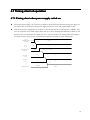
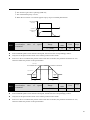
4.7 Timing chart of operation................................................................................................. 53
4.7.1 Timing chart when power supply switch on.......................................................... 53
4.7.2 Alarm timing chart while servo-ON is executed....................................................54
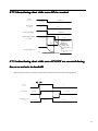
4.7.3 Action timing chart while servo-ON/OFF are executed during the servo motor
is in standstill.................................................................................................................. 54
4.7.4 Action timing chart while servo-ON/OFF are executed during the servo motor
is in motion..................................................................................................................... 55
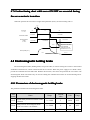
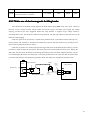
4.8 Electromagnetic holding brake......................................................................................... 55
4.8.1 Parameters of electromagnetic holding brake........................................................ 55
4.8.2 Make use of electromagnetic holding brake.......................................................... 56
Chapter 5 Parameters................................................................................................................. 58
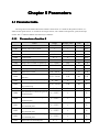
5.1 Parameter table................................................................................................................. 58
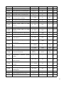
5.1.1 Parameters of section 0....................................................................................... 58
5.1.2 Parameters of section 1....................................................................................... 61
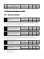
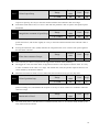
5.2 Parameter description in detail......................................................................................... 62
5.2.1 Parameters of section 0....................................................................................... 62
5.2.2 Parameters of section 1....................................................................................... 73
5.3 DI function description in detail....................................................................................... 80
5.4 DO function description in detail......................................................................................83
Chapter 6 Alarm........................................................................................................................... 84
6.1 Alarm table........................................................................................................................84
6.2 The reason and handling of alarm.....................................................................................85
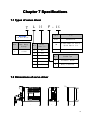
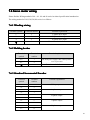
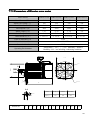
Chapter 7 Specifications............................................................................................................. 92
7.1 Types of servo driver........................................................................................................ 92
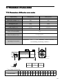
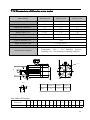
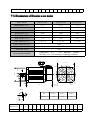
7.2 Dimensions of servo driver...............................................................................................92
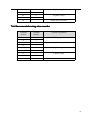
7.3 Specifications of servo driver........................................................................................... 95
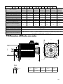
7.4 Adaptive table for servo motor selections.........................................................................96
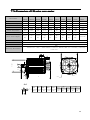
7.5 Types of servo motor........................................................................................................ 97
7.6 Servo motor wiring........................................................................................................... 98
7.6.1 Winding wiring...................................................................................................... 98
7.6.2 Holding brakes.......................................................................................................98
7.6.3 Standard Incremental Encoder............................................................................... 98
7.6.4 Incremental Encoder with Fewer Line...................................................................99
7.7 Parameters of servo motor.............................................................................................. 100
7.7.1 Parameters of 40 series servo motor................................................................. 100
7.7.2 Parameters of 60 series servo motor................................................................. 101
7.7.3 Parameters of 80 series servo motor................................................................. 102
7.7.4 Parameters of 90 series servo motor................................................................. 103
7.7.5 Parameters of 110 series servo motor............................................................... 104
7.7.6 Parameters of 130 series servo motor............................................................... 105
7.7.7 Parameters of 150 series servo motor............................................................... 106
7.7.8 Parameters of 180 series servo motor............................................................... 107
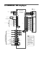
Appendix A Model for SIEMENS numerical control system.............................................. 109
A.1 SIEMENS 801 and 802S numerical control system...................................................... 109
A.1.1 Parameters setting............................................................................................... 109
A.1.2 SIEMENS 801 and 802S wiring diagram........................................................... 110
Remarks
Chapter 1 Product inspection and
installment
1.1 Product inspection
This product has made the complete function test before delivery, for prevented the
product to be abnormal owing to shipping process, please make detail inspection as the
following items after breaking the seal:
� Inspect the types of servo driver and servo motor and ensure that are the same types in
the order form.
� Inspect the outward appearance of servo driver and servo motor to see any abrasion or
damage; if so please do not wire to the power supply.
� Inspect the parts of servo driver and servo motor to see any loosen parts such as loosened
or fallen off screw.
� Rotate the servo motor shaft by hand and should be smooth rotation. However, the servo
motor with holding brake is unable to rotate directly.
If there is any break down item or abnormal phenomenon mentioned above, please
contact with the dealer immediately.
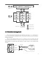
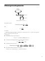
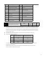
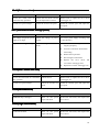
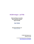
1.2 Product nameplate
Product T ype
Brand
Logo
Product N am e
Inspections Logo and
D ate Before D elivery
The Ma in Loop
Power Supply
Volta ge
R ated Output
C urrent /Pow er
Serial N um ber
P r oduc t ID
W arning Logo
el
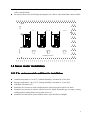
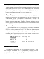
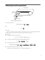
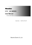
1.3 Product front pan
pane
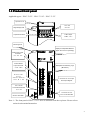
Applicable types:EP1C-TL05F、EP1C-TL10F、EP1C-TL15F
Opened C o ve r
5 D igit D isplay LED
4 Operation Buttons
Mini USB
interface
2 LED Lamps
(POWER 、R U N )
Mounting Hole
Display And Operation Buttons
(Open the cover for operating )
Main Power Input
T erminals
(L1、L2、L3)
Control Power
Input Terminals
(L1C、L2C)
External brake
resistor
Terminals (Choosing
from P ,B1 o r B 2)
Nameplate And Warning Logo
(Broadside )
Connector X 1 For Input
And Output Signals
S e r vo motor
Connection terminals
(U、V、W)
Ground Terminals
Connector X2 F or
S e r vo motor Encoder
Note 1:The front panel of EP1C-TL25F drive is different from above picture. Please refer to
main circuit terminal instruction.
2
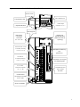
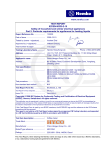
Applicable types:EP1C-TL35F and EP1C-TL55F
Opened C over
Mini USB interface
5 Digit Display LED
2 LED Lamps
(PO W E R、R U N )
4 Operation Buttons
Mounting Hole
Main Power
Connecting
T erm inals
(L1、L2、L3)
External brake resistor
Terminals (Choosing
from N C,P or B )
DC Reactor
Terminals(Choosing
f r om N 1 o r N 2)
S e rvo motor
Connection terminals
(U、V、W)
Display And
Operation Buttons
(Open the cover for
operating)
Nameplate And Warning
Logo
(B ro a ds id e )
Connector X 1 For Input
and Output Signals
Connector X 2 F or
S e rvo motor
Encoder
Control Power
connecting T erm inals
(L1C、L2C)
Ground Terminals
3
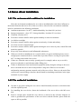
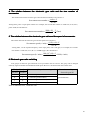
1.4 Servo driver installation
1.4.1 The environmental conditions for installation
Since the environment conditions for servo driver installation have the direct influence to
the normal function and service life of the servo driver, therefore the environment conditions
must be conformed to the following conditions:
� Ambient temperature: 0 to 40℃; Ambient humidity: less than 80% (no dew).
� Storage temperature: -40 to 50℃; Storage humidity: less than 93% (no dew).
� Vibration: less than 0.5G.
� Preventive measure shall be taken against raindrop or moist environment.
� Avoid direct sunlight.
� Preventive measure shall be taken against corrosion by oil mist and salinity.
� Free from corrosive liquid and gas.
� Preventive measure shall be taken against entering the servo driver by dust, cotton fiber and
metal tiny particle.
� Keep away from radioactive and inflammable substances.
� When several driver installments in a control cubicle, for good ventilation please reserve
enough space around each driver, install fans to provide effective cooling, keep less than
40℃ for long-term trouble-free service.
� If there are vibration sources nearby (punch press for example) and no way to avoid it,
please use absorber or antivibration rubber filling piece.
� If there is disturbance from interferential equipment nearby along the wirings to the servo
driver can make the servo driver misoperation. Using noise filters as well as other
antijamming measure guarantee normal work of the servo driver. However, the noise filter
can increase current leakage, therefore should install an insulating transformer in the input
terminals of power supply.
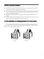
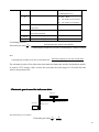
1.4.2 The method of installation
�
�
�
In order to get good cooling the servo driver should normally mount in vertical direction
with the topside upward.
For installing the servo driver, fasten the backboard of the servo driver with M5 screw
bolt.
Reserve enough space around the servo drivers as shown in the reference diagram. In
order to guarantee the performance of the servo driver and the lifetime, please make the
space as full as possible.
4
�
>100mm
�
To provide vertical wind to the heat sink of the servo driver should install ventilating fans
in the control cubicle.
Prevent the dust or the iron filings entering the servo driver when install the control cubicle.
>5 0 m m
>1 0 0 m m
>100mm
>5 0 m m
Ventilating Direction
1.5 Servo motor installation
1.5.1 The environmental conditions for installation
�
�
�
�
�
�
Ambient temperature: 0 to 40℃; Ambient humidity: less than 80 %( no dew).
Storage temperature: -40 to 50℃; Storage humidity: less than 93 %( no dew).
Vibration: less than 0.5G.
Install the servo motor in well-ventilated place with less moisture and a few dusts.
Install the servo motor in a place without corrosive liquid, flammable gas, oil vapor, cutting
cooling liquid, cutting chips, iron powder and so on.
Install the servomotor in a place without water vapor and direct sunlight.
5
1.5.2 The method of installation
�
�
�
�
For horizontal installation: In order to prevent water, oil, etc. from entering inside of the
servomotor, please put the cable connector downward.
For vertical installation: if the shaft of the servo motor is in upward direction with a speed
reducer, some prevention measure shall be taken against entering inside of the servo motor
by oil come from the speed reducer.
Motor shaft extension should be long enough, or may cause vibration while motor is in
running.
In case of installation or removing the servomotor, please do not hit the servo motor with a
hammer, otherwise the shaft and the encoder can be damaged.
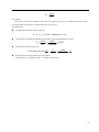
1.6 The definition of rotating direction for servo motor
The motor rotating direction description in this handbook is defined as facing the shaft of
the servo motor, if the rotating shaft is in counterclockwise direction will be called as positive
direction, or in clockwise as reversal direction.
Positive R otation
(C C W )
R eversal R otation
(C W )
6
Chapter 2 Wiring
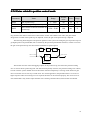
2.1 System construction and wiring
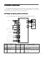
2.1.1 Servo driver wiring diagram
Input Power Supply 3 P hase A C 2 2 0 V
Input 3 P has e A C 3 8 0 V
R S T
N orm ally , a transformer is
n e e d e d to switch to get 3phase 2 2 0 VAC power
supply as the right picture .
3 8 0 V-2 2 0 V
3 Phase AC
Transform er
Circuit Breaker
O ver -current Protection
O utput 3 P has e A C 2 2 0 V
F ilter
Prevents the external noise
from interfering servo drive
E P 1C Servo Driver
Electromagnetic
Contactor
Need to install
a surge
absorber
Controller Signal C able
CN C
S y s te m /PLC or
other U pper
C ontrolle r
If th e m ain Power Supply is 3
P hase A C 2 2 0 V, please connect
to terminals of (L1/L2/L3)
If the c ontrol Power Supply is
Single Phase AC 2 2 0 V, please
connect to terminals of (L1C/L2C)
4 lines of Servomotor
Power cable are
connected to U /V/W
T erm inals of servo
driver .
DO NOT connect
w rongly !
S e r vo motor
Encoder Cable
S e r vo motor Power Cable
Ground Terminals
AC Servo Motor
7
2.1.2 Wiring explanations
Wiring Notes:
�
�
�
�
�
�
�
�
�
According to electric wire specification, use the wiring materials.
The control cable length should be less than 3 meters and the encoder cable length 20
meters.
Check that the power supply and wiring of L1, L2, L3 and L1C, L2C terminals are correct.
Please do not connect to 380V power supply.
The output terminals(U,V,W) must be connected with the servo motor connections
(U,V,W) correspondently, otherwise the servo motor will stop or over speed. However, by
exchanging three-phase terminal cannot cause the motor to reverse; this point is different
from asynchronous motor.
Earthed wiring must be reliable with a single-point connection.
Pay attention to the correct direction of freewheel diode which is connected with the relay
at the output terminal, otherwise can cause the output circuit breakdown.
In order to protect the servo driver from noise interference that can cause malfunction,
please use an insulation transformer and noise filter on the power lines.
Wiring the power lines (power supply line, main circuit lines, etc.) at a distance above
30cm from the control signal wires, do not lay them in one conduit.
Install a non-fuse circuit breaker that can shut off the external power supply immediately
for in case of the servo driver fault.
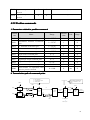
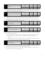
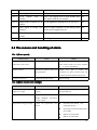
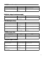
2.1.3 Electric wire specifications
Connect terminal
Symbol
Wire specification
Main power supply
L1、L2、L3
1.5~4mm
Control power supply
L1C、L2C
0.75~1.0mm
Servo motor
U、V、W
1.5~4mm
2
2
2
2
1.5~4mm
Ground
Control signals
X1
≥0.14mm2(AWG26),shielded
Encoder signals
X2
≥0.14mm2(AWG26),shielded
Regenerative Resistors
Terminal
P、B1/P、B
1.5~4mm
2
Must use a twisted pair wire cable for the encoder signal wiring. If the encoder signal cable
is too long (>20m), in which the encoder power supply can be insufficient, may use multi-wire
or thick wire for the power supply wiring.
8
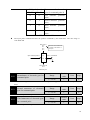
2.1.
2.1.44 Servo motor and AC power supply wiring diagrams
The power supply for the servo driver is a three-phase AC 220V which generally come
from three-phase AC380V power supply through a transformer. In peculiar circumstance, the
small servomotor, which is less than 750W, can use single-phase AC220V (L1 and L2 terminals
connect to single-phase power supply. Leave L3 terminal unconnected).
Applicable types: EP1C-TL05F、EP1C-TL10F、EP1C-TL15F、EP1C-TL25F
3 Phas e AC 2 2 0 V
T
S
R
Servo D river
1Q F
Servo motor
F IL
1K M
L1
L2
L3
U
M
V
W
L 1C
L 2C
M ain Power M ain Power
O FF
U
V
W
P
O N
1K M
1R Y
B1
ENC
X2
B2
1K M
D
PR T
Servo R eady
X1
RDY
1R Y
D C 24V
DO 1
4
D O
COM
18
1Q F : Circuit Breaker
F I L : Noise Filter
1K M : Electrom agnetic Contactor
1R Y : R elay
P R T : Surge Absorber
D : D IO D E
DO Public Term inal
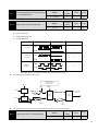
Applicable types: EP1C-TL35F、EP1C-TL55F [note]
3 P has e A C 2 2 0 V
T
S
R
Servo D river
1Q F
Servo m otor
F IL
L1
L2
L3
1K M
U
V
W
U
M
V
W
L 1C
L 2C
OFF
ON
1R Y
1K M
1K M
PR T
Brake resistor
M ain Power M ain Power
N C
P
D
X1
RDY
1R Y
DC 24V
DO Public Term inal
ENC
B1
B2
Servo R eady
X2
B
DO 1
4
D O
COM
18
1 Q F : Circuit Breaker
F I L : Noise Filter
1 K M : Magnetic Contactor
1 R Y : R e la y
P R T : Surge Absorber
D : F r e e-wheeling Diode
9
Note: there is no internal regenerative resistors in EP1C-TL55F. When the external
regenerative resistors is connected, please crossover it to the terminal P and B of
EP1C-TL55F and leave the NC unconnected.
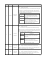
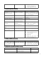
2.1.5 Main circuit terminal explanation
Terminal name
Main power
supply
Control power
supply
Regenerative
Resistors
Terminal
Power supply
higher harmonic
restrain, please
use DC reactor
connection
terminals
Symbol
Model
Detailed explanation
L1、L2
EP1C-TL05F
Connect to external AC power supply
3 phase 220VAC -15%~+10% 50/60Hz
L1、L2、
L3
EP1C-TL10F、
EP1C-TL15F、
EP1C-TL25F、
EP1C-TL35F、
EP1C-TL55F
Connect to external AC power supply
1 phase 220VAC -15%~+10% 50/60Hz
L1C、L2C
EP1C Series
Connect to external AC power supply
1 phase 220VAC -15%~+10% 50/60Hz
P,B1,B2
EP1C-TL05F、
EP1C-TL10F、
EP1C-TL15F、
EP1C-TL25F
when the external regenerative resistors is
needed, please disconnect B1 and B2[note 2]
and crossover it to terminals P and B1.
Leave B2 unconnected.
NC,P,B
N1,N2
when the external regenerative resistorsis
EP1C-TL35F、
needed, please disconnect P and B, and
EP1C-TL55F【Note1】 crossover it to terminals P and B. Leave B2
unconnected.
EP1C-TL35F、
EP1C-TL55F
U
Servo motor
V
U phase output to servomotor
EP1C Series
W
Ground
When it is needed to restrain the power
supply higher harmonic, please connect the
DC reactor between N1 and N2[note 2]
V phase output to servomotor
W phase output to servomotor
EP1C Series
Ground terminal of servomotor
Ground terminal of servo driver
Note1 : there is no internal regenerative resistors in EP1C-TL55F. When the external
regenerative resistors is connected, please crossover it to the terminal P and B of EP1C-TL55F,
and leave NC unconnected.
10
Note 2: the factory default is the interior regenerative resistors connection: B1 and B2 are in
the state of short-circuited; N11 and N2 are in the state of short-circuited.
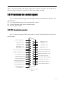
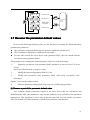
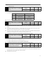
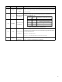
2.2 X1 terminals for control signals
The X1 connector DB25 plug provides the signals interfaced with the host-controller. The
signal includes:
� Five programmable inputs; Three programmable outputs;
� Analog command inputs; Pulse command inputs;
� Encoder signal outputs.
2.2.1 X1 terminal connector
The X1 connector plug uses DB25 male head, the contour and pin disposition charts are as
the followings:
DI Power Supply(C O M + )
1
Digital Input 2 (D I2)
2
Digital Input 4 (D I4)
3
Digital Output 1 (D O 1)
4
Digital Output 3 (D O 3)
5
Position Command Direction -(S I G N -)
6
Encoder Signal Ground (G N D ) 1 0
Encoder Signal B Output (O B + )
Encoder Signal Z Output (O Z + )
15
Digital Input 3 (D I3)
16
Digital Input 5 (D I5)
17
Digital Output 2 (D O 2)
18
20
8
Analog Command Input -(A S -) 9
Encoder Signal A Output (O A + )
Digital Input 1 (D I1)
DO Common Terminal( D O C O M )
19
Position Command Pulse -(P U L S -) 7
Not Used (Do not connect)
14
11
12
Position Command Direction + ( S I G N + )
Position Command Pulse + ( P U L S + )
21
22
Not Used (Do not connect)
Z Signal Open -collector Output (C Z )
23
Encoder Signal /A Output(O A -)
24
Encoder Signal /B Output(O B -)
25
13
Encoder Signal /Z Output(O Z -)
Shield Protection Ground
(Connector case )
X1 Connector of Servo
Driver
11
13
1
25
14
Connector X1 Soldering Lug Disposition
2.2.2 X1 terminal signal explanation
Name of signals
Digital
inputs
Digital
outputs
Position
command
pulse
Output
signals of
encoder
Shielded
cable
ground
protection
Pin number
Functions
Connector
DI1
DI2
DI3
DI4
DI5
14
2
15
3
16
Optocoupler input;
Function is programmable;
Defines by parameter P100 to P104.
C1
COM+
1
DI power supply (DC12V~24V).
DO1
DO2
DO3
4
17
5
Photo isolation output;
Maximum
output:
50mA/25V;
Function is programmable;
Defines by parameter P130~P132.
DOCOM
18
DO common terminal
PULS+
PULSSIGN+
SIGN-
20
7
19
6
High speed photo isolation input;
Working mode set by parameter
P035:
�
Pulse + SIGN;
�
Positive/Reverse pulse;
� Orthogonal pulse.
C3
OA+
OAOB+
OBOZ+
OZCZ
11
23
12
24
13
25
22
Outputs of differential driver (Line
Driver) after the frequency division
of encoder signal.
C5
GND
10
Metal
case of
connector
Open collector output of Z signal.
Encoder signal ground.
C2
C6
Shielded wire for connection with
shielded cable.
12
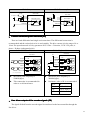
2.2.3 X1 terminal interface type
The followings introduce the X1 various interface circuits and the wiring ways with the
host-controller.
1. Digital input interfaces (C1)
For carrying on a control, the digital input interface circuit can be constructed by switch,
relay, open-collector triode, and photo-coupler and so on. To avoid contacting problem the relay
must be chosen with low current operation. External voltage is in the range of DC12V~24V.
C1-1:Switch input
C1-2:Open collector triode
Servo D river
Servo Driver
D C 1 2 V~2 4 V
D C 1 2 V~2 4 V
C O M + 1 4.7KΩ
D I1
D I2
D I3
D I4
D I5
14
2
15
3
16
C O M + 1 4.7KΩ
0V
D I1
D I2
D I3
D I4
D I5
14
2
15
3
16
2. Digital output interfaces (C2)
The digital outputs use Darlington photo-coupler. It can be connected with relay,
photo-coupler. Matters of note are:
� Inverting the polarity of DC power source, which is provided by the user, can cause the
servo driver damage.
� The maximum voltage of external DC power supply is 25V, the maximum output current is
50mA, and the total current for three channels is not in excess of 100mA.
� When using relay like inductive loads, a free-wheel diode must be connected with the
inductive load in parallel. If the diode connects in wrong direction can cause damage to the
output circuit.
� Owing to the low level of output is approximately 1V and cannot satisfy the TTL low-level
request, therefore cannot directly connect with the TTL circuit.
13
C2-1:Relay
R e la y
D C 5V~2 4 V
C2-2:Photo coupler
D C 5V~2 4 V
Servo Driver
DO1 4
D O 2 17
DO3 5
DOCOM
Servo D river
DO1 4
D O 2 17
DO3 5
Max Output 5 0 m A
18
DOCOM
0V
�
Max Output 5 0 m A
18
0V
Freewheel diode must be connected.
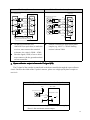
3. Position command pulse interfaces (C3)
There are both differential and single end connections. The differential connection is
recommended and the twisted pair wire is used suitably. The drive current is in the range of 8 to
15mA.The operation mode is set by parameter P035: Pulse + Direction, CCW/ CW pulse, A
phase + B phase (orthogonal pulse).
C3-1:Differential drive
C3-2: Single end drive
Servo Driver
Servo Driver
P U LS + 2 0
VC C
P U LS + 2 0
75 Ω
P U LS - 7 7 5 Ω
S IG N + 1 9
S IG N Line D river
R
P U LS - 7 7 5 Ω
1kΩ
S IG N + 1 9 7 5 Ω
R
S IG N - 6
1kΩ
75 Ω
6 75 Ω
75Ω
75Ω
1kΩ
1kΩ
2 6 L S 3 1 E quiv alent c hip
�
�
Maximum pulse frequency is
500kHz(kpps);
This connection is recommended in
order to avoid interference.
�
�
Maximum pulse frequency is
200kHz(kpps);
Resistance value of R is recommended.
VCC
R
5V
82Ω~120Ω
12V
510Ω~820Ω
24V
1.5kΩ~2kΩ
4. Line driver outputs of the encoder signals (C5)
The signal divided from the encoder signal is transferred to the host-controller through the
line driver.
14
C5-1:Long line receiver
C5-2: Photoelectric coupler receiver
Servo Driver
Servo Driver
2 6 L S 3 2 Equivalent chip
26 LS 31
OA-
26 LS 31
High Speed Photo-coupler
O A + 11
GND
23
OB+
12
OB-
24
OZ+
13
OZ-
25
GND
10
B
24
O Z + 13
OZ -
OA-
A
23
O B + 12
OB -
OA+
11
Z
25
10
A
B
Z
Must connect both side grounds
�
�
On the host controller uses
AM26LS32(or equivalent) to make the
receiver, must connect the terminal
resistance, the value is 220Ω~470Ω;
Encoder signal (GND) of servo driver
must connect with the ground terminal
on host controller.
�
On host controller use high-speed photo
coupler (e.g. 6N137); Current limiting
resistor is about 220Ω.
5. Open-collector output of encoder Z signal (C6)
The Z signal of the encoder is transferred to the host-controller through the open-collector
circuit. Because the width of the Z pulse is narrow, please use a high-speed photo-coupler to
receive it.
C6: Open collector output of encoder Z signal
VC C
Servo Driver
High S peed P hoto -c oupler
Max output 5 0 m A /3 0 V
CZ
22
GND
10
Z
0V
�
30V is the maximum voltage of external power supply;
50mA is the maximum current output.
15
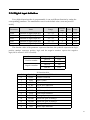
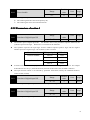
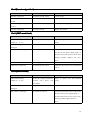
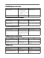
2.2.4 Digital input definition
Every digital input interface is programmable, it can act different function by setting the
corresponding parameter. The manufacturer sets it as the default value, users may need to
modify.
Parameter
Name
Range
Default
value
Unit
Usage
P100
Function of digital input DI1
-21~21
1
ALL
P101
Function of digital input DI2
-21~21
2
ALL
P102
Function of digital input DI3
-21~21
3
ALL
P103
Function of digital input DI4
-21~21
4
ALL
P104
Function of digital input DI5
-21~21
20
ALL
The absolute value of the parameter expresses functions; the symbolic expresses the logic,
positive number expresses positive logic and the negative number express the negative
logic(ON is effective, OFF is invalid):
Parameter
Positive number
Negative number
DI input signal
DI Result
Turn off
OFF
Turn on
ON
Turn off
ON
Turn on
OFF
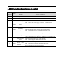
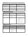
DI function table:
Ordinal
Symbol
DI Function
0
NULL
1
SON
Servo enable
2
ARST
Clear alarm
3
CCWL
CCW drive inhibition
4
CWL
5
TCCW
6
TCW
CW torque limitation
15
EMG
Emergency stop
18
GEAR1
Electronic gear switching 1
19
GEAR2
Electronic gear switching 2
20
CLR
Clear position deviation
21
INH
Pulse input inhibition
Not have function
CW drive inhibition
CCW torque limitation
16
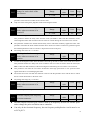
2.2.5 Digital output definition
Every digital output interface is programmable, it can act different function by setting the
corresponding parameter. The manufacturer sets it as the default value, users may need to
modify.
Name
Range
Default
value
P130
Function of digital output DO1
-11~11
2
ALL
P131
Function of digital output DO2
-11~11
3
ALL
P132
Function of digital output DO3
-11~11
8
ALL
Parameter
Unit
Usage
The absolute value of the parameter expresses functions; the symbolic expresses the logic.
'0' is forcing OFF, '1' is forcing ON. The symbol indicates the output logic, the positive
number expresses the positive logic and the negative number expresses the negative logic:
Parameter value
Positive number
Negative number
Function
DO output signal
ON
Turn on
OFF
Turn off
ON
Turn off
OFF
Turn on
DO function table:
Ordinal
Symbol
DO Function
0
OFF
Always invalid
1
ON
Always valid
2
RDY
Servo ready
3
ALM
Alarm
5
COIN
Positioning complete
6
ASP
Arrival speed
8
BRK
Electromagnetic brake
11
TRQL
Torque under limitation
17
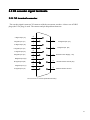
2.3 X2 encoder signal terminals
2.3.1 X2 terminal connector
The encoder signal connector X2 connects with the servomotor encoder. A three row of DB15
plugs (the VGA plug) is used. The contour and pin disposition charts are:
V Signal Input (V-)
6
1
11
V Signal Input (V+ )
/W Signal Input (W-)
7
/U Signal Input (U-)
2
12
W Signal Input (W+ )
U Signal Input (U+ )
Z Signal Input (Z-)
Z Signal Input (Z+ )
B Signal Input (B-)
B Signal Input (B+ )
A Signal Input (A-)
A Signal Input (A+ )
8
3
13
Encoder Power Supply ( + 5V)
9
4
14
Encoder Power Ground (0V)
10
5
15
Shield Protection Ground
Servo D rive X 2 Connector (Standard Encoder)
18
Not Used (Do not connect )
6
Not Used (Do not connect )
1
Not Used (Do not connect )
7
Not Used (Do not connect )
2
11
Not Used (Do not connect )
12
Not Used (Do not connect )
8
Z Signal Input (Z-)
3
Z Signal Input (Z+ )
1 3 Encoder Power Supply ( + 5V)
9
B Signal Input (B-)
14
4
B Signal Input (B+ )
Encoder Power Ground (0V)
10
A Signal Input (A-)
15
5
A Signal Input (A+ )
Shield Protection
Ground
Servo Drive X 2 Connector (Wireless Encoder )
5
1
10
15
6
11
Connector X2 Soldering Lug Disposition
2.3.2 X2 terminal signal explanation
Colour of wire
Signal name of encoder
5V
Standard
(16core)
[note1]
Wire
saving
(10core)
[note2]
13
Red+Red
/White
Red+Red
/White
14
Black+Bl
ack
/White
Black+Bl
ack
/White
Pin
number
Power supply
0V
Functions
Use 5VDC power supply
(provided by servo driver).If
the cable is longer than 20m,
in order to prevent encoder
from voltage drop down, it
is better to use multi wire or
19
thick wire for power line and
ground line.
A+
A phase input
B phase input
Z phase input
U phase input
V phase input
W phase input
Shield ground
5
Brown
Brown
A-
10
Brown/W
hite
Brown/W
hite
B+
4
Yellow
Yellow
B-
9
Yellow
/White
Yellow
/White
Z+
3
Green
Green
Z-
8
Green/W
hite
Green/W
hite
U+
2
Purple
U-
7
Purple
/White
V+
1
Blue
V-
6
Blue/Whi
te
W+
12
Orange
W-
11
Orange
/White
FG
15
Bare wire
Connect with A phase
output of encoder.
Connect with B phase output
of encoder.
Connect with Z phase output
of encoder.
Connect with U phase
output of encoder.
Not connect for wire saving
Connect with V phase
output of encoder.
Not connect for wire saving.
Connect with W phase
output of encoder.
Not connect for wire saving.
Bare wire
Connect with cable shield
wire.
Note: The optional extras provided by Maxsine:
1. 16 core cable for the type of 16FMB15. (for using in the 110 and above frame of
servomotor).
2. 10 core cable for the type of 10FBM15X.. (for using in the 80 frame of servomotor).
20
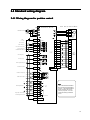
2.4 Standard wiring diagram
2.4.1 Wiring diagram for position control
Star Series Servo Motor
E P 1C Servo Driver
L1
L2
L3
3 Phase AC 2 2 0 V
QF
KM
U
V
W
L1C
L2C
Se rvo On (S O N )
Alarm Clear (A R S T )
C C W Drive Inhibition (C C W L )
C W Drive Inhibition (C W L )
Position Deviation Clear (C L R )
COM+
DI 2
DI 3
DI 4
DI 5
DO 1
Se rvo Ala rm (A L M )
DO 2
Electrom agnetic Brake (B R K )
DO Common Terminal
DO 3
DO
COM
4
4 Cores Power
Connector
1
13
5V
2
14
0V
3
5
A+
4
10
A-
7
4
B+
5
9
B-
8
3
Z+
6
8
Z-
9
2
U+
10
7
U-
13
1
V+
11
6
V-
14
12
W+
12
11
W-
15
15
FG
1
14
2
15
3
16
2 6L S 3 2
Receiver
X1
Servo Ready( R D Y )
3
W
X2
4.7kΩ
DI 1
2
V
1
X1
DC
1 2 ~2 4 V
U
4
17
5
18
Op tica l
Encoder 1 5
Cores
Connector
X2 M etal Case
X1
P U LS +
20
Position Command(PU L S )
P U LS -
7
S IG N +
19
S IG N -
6
A
OA +
11
A
OA -
23
B
OB +
12
B
OB -
24
Z
OZ+
13
OZ-
25
Z Signal Open -collector Output
CZ
22
Encoder Signal Ground G N D
GND
10
Position Command(S I G N )
75 Ω
75 Ω
75 Ω
75 Ω
X1
A
B 26LS31
Encoder Signal Outputs
D rive r
Z
Z
N o t ee::
The DI and DO terminals have
M ulti -functions programmed by
softw are . Their default settings
shown in picture can use for
common purposes . User can
modify it according to different
needs .
Signal Ground
FG
X1 M etal C ase
21
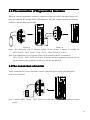
2.5 The connection of Regenerative Resistors
When an external regenerative resistors is connected to the servo driver, the short circuit wire
between connector B1 and B2 must be disconnected. Then the external regenerative resistors
could be connected between P and B1.
Picture A
Picture B
Note1: the connection way of external resistor, as the picture A shows, is suitable for
EP1C-TL05F、EP1C-TL10F、EP1C-TL15F、EP1C-TL25F servo drive .
Note 2: the connection way of external resistor, as the picture B shows, is suitable for
EP1C-TL35F、EP1C-TL55F servo drive. When the external regenerative resistors is used,
please connect to the terminal P and B, leave the NC unconnected.
The connection of reactor
2.6
2.6T
Please connect the DC reactor between N1 and N2 when the power supply ultra-harmonics
needs to be restrained.
电
抗
器
Note 1: only the EP1C-TL35F、EP1C-TL55F servo drive have the function to connect external
reactor.
22
Remarks
23
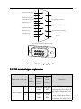
Chapter 3 Front panel operation
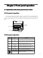
3.1 Explanation of the front panel of servo driver
3.1.1 Front panel compositions
The front panel consists of the display (5-digit, 7-segment LED), four switching buttons (8,
2, 4, and 5) and one Mini USB interface. It displays monitor status, parameters and changes the
parameter setting value and so on. The main menu is in cascade sequence mode and executes in
layer.
M ini USB
interface
5 D igital LED
4 B uttons
2 LED Lam ps
3.1.2 Front panel explanations
Symbol
Name
Functions
POW
Main power
lamp
Lit: Main power supply already turn on;
Go out: Main power supply did not turn on.
RUN
Running lamp
8
Increasing
button
Increase sequence number or value;
Press down and hold to repeat increasing.
2
Decreasing
button
Decrease sequence number or value;
Press down and hold to repeat decreasing.
4
5
Exit button
Menu exit; cancel the operation.
Lit: Servomotor is active;
Go out: Servomotor is not active.
Confirm button
Menu entered; the operation confirmed.
USB interface
Connect to computer
24
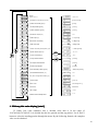
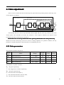
3.1.3 Data display
A number is shown by five digital displays; a minus symbol in front of the value
represents a negative value; the lit decimal points in all the digits indicate a negative 5-digit
value. Some displays have a prefix character. If the value is full-scale, then the prefix character
can be omitted.
12345 ,Positive num ber .
12345
-1 2 3 4 ,4 digit or less negative num ber , “”sym bol expresses negative num ber .
-1 2 3 4
1.2.3.4.5.
-12345 ,5 digit negative num ber expressed by
lighting the decim al points in all digits .
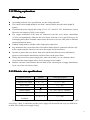
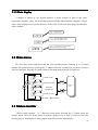
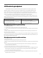
3.2 Main menu
The first layer is the main menu and has four operating modes. Pressing '8' or '2' button
changes the operation mode. Pressing the '5' button enters the second layer and then executes a
concrete operation. Pressing '4' button returns to the main menu from the second layer.
D-
Status monitor
En ter
P-
Parameter setting
E-
Parameter
management
A-
Auxiliary function
Second
layer
First layer(M ain m enu )
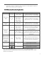
3.3 Status monitor
Choose status monitor " d- " under the main menu. Pressing the '5' button enters the
monitor mode. There are many kinds of monitor's project; Use '8' and '2' button to select the
needing project. Pressing the '5' button again enters the concrete status display.
25
D-S P d
Motor
sp e e d (r/m i n )
D-[P.
Initial position command (input puls e )
r1 0 0 0
1 0 0 0 r/m i n
Lo
[n o te1] [ n o te 2]
D-[P o
Position command (p u lse )
Lo
[n o te1]
D-P o s
Current position (p u lse )
Lo
[n o te 1]
D-E P o
Position deviation (p u lse )
Lo
[n o te 1]
D-t r q
Servomotor torque ( % )
T
50
50 %
D-P t
Peak torque ( % )
T
80
8 0 % [n o te 4]
D-i
Servomotor current(A)
i
2.3
2.3A[n o te 3]
D-P i
Peak current(A)
i
5.6
5.6A[n o te 4]
D-F r q
Position command pulse frequency (k H z)
F 1 2 .5
1 2 .5k H z [n o te 5]
D-[S
Speed command (r/m in )
R. -3 5
-3 5 r/m i n
T. -2 0
-2 0 %
En ter
D-[t
Torque command ( % )
D-D i
DI input terminal status
D-D o
DO output terminal status
&#$
[n o te 6]
%*
[n o te 7]
##!
[n o te 8]
D-[o d
Encoder input signals
D-A P o
Rotor absolute position (p u lse )
A3 2 8 9
3289 p u lse [n o te 9]
D-L d
Accumulative load factor ( % )
Ld 4 5
45 %
D-r G
Duty factor of regeneration braking (% )
rG 3 0
30 %
D-[n t
Control mode
P o s -1
[n o te 1 0 ]
D-E r r
Alarm code
Err - -
N o a la rm [n o te 1 1 ]
D-r E
R eserved
rE
R eserved
D-U
Bus voltage
U 300
300 V
D-t[
Module internal temperature
Tc 5 0
50 ℃
0
1. 32 binary bits value display [note1]
32 binary bits value translates into a decimal value that is in the range of
-2147483648~147483647. It is divided into the low portion and the top portion. Use '8' and '2'
button to select the needing portion through the menu. By the following formula, the complete
value can be obtained.
26
LO
Bottom digit
Hi
T op digit
En ter
12345
6
Result =612345
3 2 bit number =top digit number× 100000+bottom digit number
2. Pulse unit [note2]
The original position command pulse is the input pulse count that has not transformed
through the electronic gear. The pulse count unit for other parts is the same with the encoder
pulse unit. Take a 2500 lines encoder as the example.
Encoder pulse unit = encoder resolution
= 4 × encoder line
= 4 × 2500( pulse / rev)
= 10000( pulse / rev)
3. Motor current [note3]
The servomotor current is Irms.
4. The servomotor current is Irms. [note 4]
The maximum torque and maximum Irms of the servomotor in previous 10-second
duration is defined as the peak value.
5. Position command pulse frequency [note5]
The frequency of position command pulse is the actual pulse frequency before the
electronic gear. The positive number is shown as positive direction and the negative number as
reverse direction.
6. Input terminals DI [note6]
A vertical segment of LED shows an input status. The lit top vertical segment shows the DI
input to be “ON” and the lit bottom vertical segment to be “OFF”.
27
D igital input :
DI5
ON
s tatus :
DI4
DI3
OFF
ON
DI2
DI1
OFF
ON
O N : upper vertical segm ent is lit
O F F :bottom vertical segm ent is lit
7. Output terminals DO [note7
[note7]]
A vertical segment of LED shows an output status. The lit top vertical segment shows the DO
output to be “ON” and the lit bottom vertical segment to be “OFF”.
D igital output :
Sta tu s :
DO3
OFF
DO2
ON
DO1
ON
O N : upper vertical segm ent is lit
O F F :bottom vertical segm ent is lit
8. Input signals from encoder [note8]
A vertical segment of LED shows an input status. The lit top vertical segment shows a
HIGH-level signal and the lit bottom vertical segment a LOW-level signal.
S tatus :
V
U
Encoder input :
0
1
W
0
A
1
B
0
Z
0
H igh level (1):upper vertical segm ent is lit
Low level (0):bottom vertical segm ent is lit
28
9. Absolute position of rotor [note9]
The rotor position is relative to the stator in one revolution per cycle. Use the encoder
pulse unit and take the encoder Z pulse as the zero point. Take a 2500 lines encoder as the
example. The position of the rotor is in the range of 0~9999 and is zero when Z pulse appears.
10. Control mode [note10]
The first three characters show the control mode, the final character shows gain group.
S P D -1
P O S :Position control m ode
S P D :Speed control m ode
T R Q :Torque control m ode
1 :First gain group
2 :Second gain
gr oup
11. Alarm code [note11]
The " Err " followed by two minus symbols indicates no alarm and by digital number
indicates an error code number that is flickering. When alarm appears, the error code number
displays automatically on the front panel LED. During the error status, the monitor mode can
be changed to other mode by pressing buttons, but the decimal point of the last LED is still
flickering and shows existence of an alarm.
Err- Err 9
N o a la rm
flickering
9 num ber alarm
12. Module internal temperature 【note 12】
When the module temperature is more than the user setting value, the fan begins to
work; when the module temperature is less than the setting value, the fan will be turned off.
The temperature displayed range is 25~125℃。
29
ting
3.4 Parameters set
setting
The parameter number expression uses a parameter section name combined with a
parameter name. The three figures are the section name and two figures and one figure are the
1' is the section name and '02
02
parameter name. Take P102 parameter as an example, '1
02' the
P-102
parameter name. "P-102
P-102" displays on the front panel LED.
Choose the parameter mode under the main menu " P- ". Pressing the '5' button enters the
parameter-setting mode. First use '8' or '2' button to select the parameter section name and then
pressing '5' button enters the parameter name selection. Again, use '8' or '2' button to select the
parameter name and then pressing '5' button shows the parameter value.
Use '8' or '2' button to alter a parameter value. Pressing '8'('2') button once to increase
(decrease) the parameter value by one. Pressing down and hold the '8'('2') button, the parameter
value can increase (decrease) continuously. When the parameter value is modified, the decimal
point on the most right sides LED is lit. Press '5' button to confirm the parameter value to be
effective, meanwhile the decimal point turns off. The modified parameter value is immediately
active to influence on the control action (but some parameters needs to preserve firstly and then
turn off and on the power supply). Hereafter pressing '4' button returns to the parameter number
selection and can continue to modify a parameter. If the value is not satisfied, do not press the '5'
button and can press '4' button to cancel it for resuming the original parameter value.
The modified parameter did not preserve in EEPROM. For permanent preservation, please
refer to the parameter writing operation in the parameter management (3.5 sections). The
parameter section name and the parameter name are not necessarily continual, but the parameter
section name and the parameter name that are not in use will be jumped over and cannot be
chosen.
30
P-0_ _
P-1_ _
P-2_ _
Parameter section
in c . / d e c .
En ter
Parameter
number inc . / d e c .
P-0 0 0
P-1 0 0
P-2 0 0
P-0 0 1
P-1 0 1
P-2 0 1
P-0 0 2
P-1 0 2
P-2 0 2
En ter
Parameter value inc .
1 2 3 4.
Parameter value
Parameter value dec .
En ter Modification confirmed
3.5 Parameter management
Choose the parameter management mode under the main menu " E- ". Pressing the '5'
button enters the parameter management mode. The operation is performed between parameter
list and the EEPROM.
There are three operation modes. Use '8' or '2' button to select an operation mode and
then pressing down and hold the '5' button at least three seconds to active the operation mode.
After finished the operation and then pressing '4' button returns to the operation mode
selection.
E-S e t
Parameter
w r ite -i n
E-r d
Parameter
r e a d -o u t
E-d e f
Resume default
v a lu e
Press and hold
3 se co n d
En ter
done
Start
Under operation
Operation
success
Error
Operation fail
31
�
Write and save parameters
This operation indicates that the parameter in parameter list will write to the EEPROM.
When user has made change to a parameter, it only change the parameter value in parameter
list, but for the next time when the power supply is on the parameter value will restore its
original value. Making permanent change to a parameter value, it is the need to carry out the
parameter write operation and write the parameter value to the EEPROM. Hereafter, when
the power supply is on again will be able to use the new parameter value.
�
Read and fetch parameters
This operation indicates that all the parameters will be read from the EEPROM to the
parameter list. This process will carry out automatically one time when power supply is on.
At the beginning, the value of each parameter in the parameter list is the same as the
parameter in the EEPROM. After making change to a parameter value, the value in the
parameter list will also change. When the parameter value is not satisfied or comes to
confusion, carries out the parameter read operation to read back the original parameter value
from the EEPROM to the parameter list.
�
Resume default value
This operation indicates that each default value of all the parameters will read from
EEPROM and write to the parameter list and EEPROM. For the next time when power
supply is on the default parameters will be used by now. When many parameters become
confusion and cause abnormal operation, it is necessary to carry out this operation for
resuming the default parameters. There are different default parameters for different servo
driver model and the servomotor model. Therefore, before doing this operation the servo
motor code (Parameter P002) must be selected correctly.
E-S e t
Parameter write-i n :
Parameter table
EEPROM
E-r d
Parameter read-o u t: Parameter table
EEPROM
E-d e f
Resume default
va lu e :
E x -factory
default value
Parameter table、EEPROM
3.6 Auxiliary functions
Choose the auxiliary function mode " A- " under the main menu. Pressing the '5' button
enters the auxiliary function mode. Use '8' or '2' button to select an operation mode. Then
pressing the '5' button again enters the corresponding function. After finished this operation
pressing the '4' button returns to the operation mode selection.
32
A-F n
Special function
A-J O G
JOG operation
En ter
A-S r
Buttom speed
adjustment
A-A0
Analog zeroing
Corresponding
function
oper ation
3.7 Resume the parameter default values
In case of the following situation, please use the function of resuming the default parameter
(manufacture parameter):
�
The parameter is adjusted chaotically, the system is unable the normal work.
�
The servomotor is replaced by a different newly model.
�
For any other reason, the servo driver code (parameter P001) does not match with the
servomotor code (parameter P002).
The procedures for resuming the default parameter values are as the followings:
1.
Inspection servomotor code (parameter P002) whether it is correct or not. If it is not
correct,
carries out following step, or jumps to 4 step.
2.
Modify the password (parameter P000) by 360.
3.
Modify the servomotor code (parameter P002) with newly servomotor code,
referring to
chapter 7.4 servomotor adaptive table.
4.
Enter the parameter management, carries out one of following operations:
(1) Resume a part of the parameter default value
For resuming default parameters related to the servo driver and the servomotor and
maintaining the other user parameters, carry out the parameter write operation in the parameter
management. This operation is active only in that the password was 360 and the servomotor
code was modified. In other situations, it only has the parameter write function.
33
Parameter write-i n
Press and hold
for 3 seconds
En ter
E-S e t
done
Start
Under operation
Operation success
Error
Operation fail
Only resume all the default values with drive and motor
(2) Resume all of the parameter default value
Carry out to resume the default value in the parameter management, all the parameters
including the parameter modified by the user become the default value.
Resume default value
E-d e f
Press and hold for
3 seconds
En ter
done
Start
Under operation
Operation success
Error
Operation fail
Resume all of the parameter default value
5. Turn off and on the power supply, then an operation can be performed again.
34
Chapter 4 Running
4.1 Trial running with no load
The goal of trial running is confirming the following items that are correct or not:
�
The servo driver power supply wiring;
�
The servo motor wiring;
�
The encoder wiring;
�
The running direction and the servomotor speed.
4.1.1 Wiring and inspection
Before turn on the power supply, confirms the servomotor:
� The servomotor has no loading on the shaft; decoupling from the machinery if
already coupled.
� Because the servomotor has an impact during acceleration or deceleration, therefore
the servomotor must be fixed.
Follow the wiring chart, inspects the following items before turning on the power
supply:
� The wirings are correct or not. In particular, L1, L2, L3 wirings and U, V, W
wirings corresponding to the servomotor U, V, W are correct or not.
� The input voltage is correct or not.
� The encoder cable connection is correct or not.
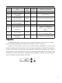
4.1.2 Trial running in JOG mode
1. Turn on power supply
Turn on the control power supply (while the main power supply temporarily turned off).
The front panel display is lit. If any error appears, please inspect the wirings. Then turn on the
main power supply, the POWER indicating LED is lit.
2. Parameter setting
Set parameters according to the following table:
Param
eter
Name
Setting
value
Default
value
Parameter explanation
P004
Control mode
1
0
Set speed control
P025
Source of speed
command
3
3
Set JOG source
P060
Acceleration time of
speed command
suitable
0
Decrease acceleration impact
P061
Deceleration time of
speed command
suitable
0
Decrease deceleration impact
P076
JOG running speed
100
100
JOG speed
P097
Neglect inhibition of
servo driver
3
3
Neglect CCW inhibition
(CCWL) and CW inhibition
(CWL).
P098
Forced enable
1 or 0
0
Set ‘1’for forced enable;
Set ‘0’for external enable.
P100
Digital input DI1
function
1
1
Set DI1 for servo enable (SON)
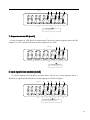
3. Operation
Confirming that there is no alarm and any unusual situation, turn on the servo enable
(SON), the RUN indicating LED lit and the servomotor is active at zero speed.
Choose the JOG running "A-JOG" in the auxiliary function. Pressing the '5' button enters
the JOG running mode. The numerical value is the speed command provided by P076 parameter
and the unit is r/min. Pressing down and hold the '8' button, the servomotor will rotate in
counterclockwise direction with the JOG speed. Loosen the pressed button, the servomotor stops
and keeps zero speed. Alternatively, pressing down and hold the '2' button, the servomotor will
rotate in clockwise direction with the JOG speed.
J 100
Press
36
4.1.3 Trial running in speed adjustment mode with keyboard
1. Turn on power supply
Turn on the control power supply (while the main power supply temporarily turned off).
The front panel display is lit. If any error appears, please inspect the wirings. Then turn on the
main power supply, the POWER indicating LED is lit.
2. Parameter setting
Set parameters according to the following table:
Para
meter
Name
Setting
value
Default
value
Parameter explanation
1
0
Set speed control
P004
Control mode
P025
Source of
command
speed
4
3
Set BUTTON source
P097
Neglect inhibition of
servo driver
3
3
Neglect CCW inhibition (CCWL) and
CW inhibition (CWL).
P098
Forced enable
1 or 0
0
Set ‘1’for forced enable;
Set ‘0’for external enable.
P100
Digital input DI1
function
1
1
Set DI1 for servo enable (SON)
3. Operation
Confirming that there is no alarm and unusual situation, turn on the servo enable (SON), the RUN
indicating LED lit and the servomotor is active at zero speed.
Choose the adjustable speed "A-Sr" in the auxiliary function. Pressing the '5' button enters the
adjustable running mode. Speed adjustable prompt of keyboard is “ r. ” . Number value unit is r/min. The
numerical value is the speed command provided by pressing '8' button (for increasing) or '2' button (for
decreasing) and the unit is 0.1r/min. Following the speed command, the servomotor is in rotation. The rotation
direction is dependent on the sign of digits. The positive number indicates positive direction (CCW) and the
negative number indicates reverse direction (CW).
r.
50
Speed
command
in c . / d e c.
37
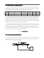
4.2 Position control mode
The position control applies in systems that need to locate precisely, such as numerical
control machine tool, textile machinery and so on. The position command is a pulse serial
coming from the input terminals PULS, PULS-, SIGN and SIGN- .
4.2.1 Simple example for position control mode
This is a simple example of positioning control. The wiring diagram is as below.
Servo Motor
L1
L2
L3
L1C
Three phase AC 2 2 0 V
QF
KM
Servo Driver
U
V
W
U
M
V
W
L2C
X1
DC
1 2 ~2 4 V
COM+
1
DI 1
14
DI 3
15
DI 4
3
X2
Servo ON
SON
CCW drive inhibition CCWL
CW drive inhibition CWL
Servo ready
RDY
DO common terminal
DO 1
4
DO
COM
18
P U LS +
20
ENC
Position command PULS
P U LS -
7
S IG N +
19
S IG N -
6
Position command SIGN
Z signal open-collector output
GND
Encoder signal ground
CZ
22
GND
10
GND
The parameter setting for the example:
Para
mete
r
Name
P004
Control mode
P097
Neglect
inhibition
servo driver
of
Setting
value
Default
value
Parameter explanation
0
0
Set position control
0
3
Use CCW inhibition (CCWL) and CW
inhibition (CWL). If neglect, did not connect
CCWL、CWL.
38
P100
Digital
input
DI1
1
1
Set DI1 for servo enable (SON)
output
DO1
2
2
Set DO1 for servo is ready(RDY)
function
P130
Digital
function
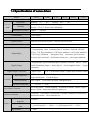
4.2.2 Position commands
1. Parameters related to position command
Param
eter
P029
P030
P031
P032
Name
1st numerator of electronic gear
Denominator numerator of electronic
gear
2nd numerator of electronic gear
Range
Default
value
1~32767
1
P
1~32767
1
P
Unit
Usage
1~32767
1
P
rd
1~32767
1
P
th
3 numerator of electronic gear
P033
4 numerator of electronic gear
1~32767
1
P
P035
Input mode of command pulse
0~2
0
P
P036
Phase of input command pulse
0~1
0
P
P037
Signal logic of input command pulse
0~3
0
P
P038
Signal filter of input command pulse
0~21
7
P
P039
Filter mode of input command pulse
0~1
0
P
0~1000
0
P040
Time-constant of exponential form
filter for position command
ms
P
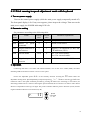
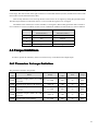
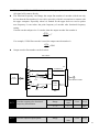
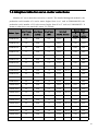
2. Transmission path of command pulse
0:Pu l s e +D irection
1:C C W pulse/C W pulse
2:A and B phases
P0 3 8
P0 3 7
PULS
P0 3 5
P0 4 0
F ilter
N
f 2 = f 1×
M
CLK
Input command
pulse f1
Counting
m ode
SIGN
Num erator N is determ ined by
G E A R 1 and G EAR 2 of D I
inputs
N um erator N
P0 2 9
P0 3 1
P0 3 2
P0 3 3
U p /D ow n
counter
DIR
F ilter
P0 3 9
P0 3 7
P0 3 6
N
— —
M
Position com m and
f2
Position
com m and f 3
Sm ooth
filte r
Denominator M
P0 3 0
Electronic gear
39
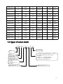
3. Input mode of command pulse
The command pulse input mode is dependent on the parameter P035. For adjusting the
counting edge of a pulse, the parameter P037 sets the phases of the PULS and the SIGN signals.
Parameter P036 uses in changing the counting direction.
CCW
Command pulse type
CW
Param eter P 0 3 5
PULS
0
P u lse +D IR
SIGN
CCW pulse/
C W pulse
PULS
1
SIGN
PULS
A p h a se+B p h a se
2
SIGN
Note: The arrow indicates the counting edge with P306=0 and P307=0.
4. Timing chart specifications of command pulse
Pulse waveform of position command
Parameter demand
Differential
Single end
tck>2μs
tck>5μs
th>1μs
th>>2.5μs
tl>1μs
tl>>2.5μs
trh<0.2μs
trh<0.3μs
trl<0.2μs
trl<0.3μs
ts>1μs
ts>2.5μs
tqck>8μs
tqck>10μs
tqh>4μs
tqh>5μs
tql>4μs
tql>5μs
tqrh<0.2μs
tqrh<0.3μs
tql
tqrl<0.2μs
tqrl<0.3μs
tqrl
tqs>1μs
tqs>2.5μs
th
tck
90%
PULS
S IG N
10%
trh
90%
ts
trl
tl
ts
10%
trh
CW
CCW
trl
P u ls e +D I R
tqck
tqh
90%
PULS
10%
tqrh
S IG N
tqs
90%
10%
tqrl
CW
tqs
tqrh
CW
CCW
A phase+B phase
40
5. Signal filter
Numeral filters related to the parameter P038 will filter the input signal PULS and SIGN.
The bigger the P308 value, the larger filter time-constant and the lower maximum repeated
frequency of input pulse. If P038 is seven, the maximum repeated frequency of input pulse
will reach 500 kHz (kpps).
If the positioning is not accurate, increase the parameter P038 in order to filter noise on
the signal cable and to avoid counting error. The SIGN filter can close by parameter P039
setting.
6. Smooth filter
The parameter P040 carries on the smooth filter to the command frequency. It has the
exponential form for acceleration and deceleration as showing in the following chart. The
filter cannot lose any input pulse, but can delay its action time. When P040 is zero, the filter
does not have any effect. The parameter value indicates the time in which the repeated
frequency increases from 0 to 63.2% command frequency.
Command pulse
frequency
0
tim e
Command
frequency after
filte rin g
0
tim e
The filter makes the input repeated frequency smooth. This filter is used in the following
situations: the host controller is without acceleration and deceleration function; the electronic
gear ratio is quite big; the command frequency is lower.
4.2.3 Electronic gear for input commands
Through the electronic gear user can define that one input command pulse will cause an
adjustable movement of mechanical device. Therefore, the host controller does not have to
consider that the gear ratio in the mechanical system and the encoder line number of the
servomotor .The electronic gear variable is illustrated in the following table.
Variable
Explanation
Value of this driver
C
Lines of encoder
2500
Pt
Resolution of encoder (pulse/rev)
=4×C
41
=4×2500
=10000(pulse/rev)
R
ΔP
R=B/A,here
A:turn number of servomotor
B:turn number of load shaft
Ratio of reducer
One
command
pulse
travel
equivalent
Pc
Command pulse numbers for one
turn of the load shaft
Pitch
Pitch of ball bearing screw (mm)
D
Diameter of rolling cylinder (mm)
Calculating formula:
N
Resolution in one turn of encoder(Pt)
Electronic gear ratio( ) =
M
Command pulse number in one turn of load shaft(Pc) × reducer ratio(R)
Here,
Command pulse number in one turn of load shaft (Pc) =
Movement quantity in one turn of load shaft
Movement quantity in one command pulse
The calculated result will be abbreviated and make the numerator and the denominator smaller
or equal to 32767 integer values. At last, the result must be in the range of 1/50<N/M<200 and
write to the parameter list.
1. Electronic gear is used for ball screw drive
lathe bench
Ball scr ew P itc h (m m )
Servom otor
R educer ratio R
Encoder resolution
P t (p u l s e /r e v )
The ball bearing screw load has
Electronic gear ratio(
N
Pt
)=
M
Pc × R
42
Here,
Pc =
Pitch
∆P
For example:
Known the encoder line number C=2500 line, the reducer gear ratio 1/1, pitches Pitch=8mm, a pulse
travel equivalent ΔP=0.001mm. Calculate the electronic gear ratio.
Calculation step:
�
Calculate the resolution of the encoder (Pt)
Pt = 4 × C = 4 × 2500 = 10000( pulse / rev)
�
Calculate the command pulse numbers for one turn of the load shaft (ball-screw) (Pc)
Pc =
�
Pitch
8mm
=
= 8000
∆P
0.001mm
Calculate the electronic gear ratio.
Electronic gear ratio(
�
N
Pt
10000
5
)=
=
=
M
Pc × R 8000 × (1 / 1) 4
Set parameters (By first numerator as an example)
Numerator N=5,denominator M=4,set P029=5 and P030=4.
43
2. Electronic gear is used for graduator drive
Graduator
R educer ratio R
Servom otor
Encoder resolution
P t (p u ls e /r e v )
The graduator load has
Electronic gear ratio(
N
Pt
)=
M
Pc × R
Here,
Pc =
360°
∆P
For example:
Known the encoder line number C=2500 line, the reducer gear ratio 1/3, a pulse travel equivalent
ΔP=0.1°Calculate the electronic gear ratio.
Calculation step:
�
Calculate the resolution of the encoder (Pt)
Pt = 4 × C = 4 × 2500 = 10000( pulse / rev)
�
Calculate the command pulse numbers for one turn of the load shaft (Pc)
Pc =
�
Calculate the electronic gear ratio
Electronic gear ratio(
�
360 ° 360 °
=
= 3600
∆P
0 .1 °
N
Pt
10000
30000 25
)=
=
=
=
M
Pc × R 3600 × (1 / 3) 3600
3
Set parameters (By first numerator as an example)
Numerator N=25,denominator M=3,set P029=25 and P030=3.
44
or belt drive
3. Electronic gear is used for convey
conveyo
Conveyer belt
Rolling
cylinder D
Reducer ratio R
Servomotor
Encoder resolution P t(p u lse /r e v )
The conveyor belt load has
Electronic gear ratio(
N
Pt
)=
M
Pc × R
Here,
Pc =
πD
∆P
For example:
Known the encoder line number C=2500 line, the reducer gear ratio 1/10, the rolling cylinder diameter
D=200mm, a pulse travel equivalent ΔP=0.001mm, Calculate the electronic gear ratio.
Calculation step:
�
Calculate the resolution of the encoder (Pt)
Pt = 4 × C = 4 × 2500 = 10000( pulse / rev)
�
Calculate the command pulse numbers for one turn of the load shaft (Pc)
Pc =
�
Calculate the electronic gear ratio
Electronic gear ratio(
�
πD 3.14 × 200
=
= 62800
∆P
0.01
N
Pt
10000
100000 2500
)=
=
=
=
M
Pc × R 62800 × (1 / 10) 62800
157
Set parameters (By first numerator as an example)
Numerator N=2500,denominator M=157,set P029=2500 and P030=157.
45
on
ic gear ratio and the turn number of
4. The relation between the electr
electron
onic
servomotor
The relation between the electronic gear ratio and the turn number of servomotor is:
Servomotor turn number=
pulse × N
Pt × M
Among them, pulse is input pulse number. For example, the encoder line number C=2500 line, N=20, M=3,
pulse=1000, the calculation is:
1000 × 20 2
= (Turn )
10000 × 3 3
Servomotor turn number=
on
ic gear ratio and the speed of servomotor
5. The relation between the electr
electron
onic
The relation between the electronic gear and the speed of servomotor is:
Servomotor speed (r / min)=
f ( Hz ) × 60 × N
Pt × M
Among them, f is the repeated frequency of the input pulse; unit is Hz (pps). For example, the encoder
line number C=2500 line, N=3, M=1, f=100kHz (kpps), the calculation is:
100 × 103 × 60 × 3
= 1800(r / min)
10000 × 1
Servomotor speed(r / min)=
6. Electronic gear ratio switching
Four groups of electronic gear numerator N are provided in the servo driver. The group can be changed
online by signal of GEAR1 and GEAR2 from DI inputs. However, the denominator M is all the same.
DI signal[note]
GEAR2
GEAR1
0
0
0
1
Numerator of input electronic gear N
1st numerator(parameterP029)
nd
2 numerator(parameterP031)
Denominator of input
electronic gear M
Denominator
(parameterP030)
rd
1
0
3 numerator(parameterP032)
1
1
4th numerator(parameterP033)
Note: 0 indicates OFF; 1 indicates ON.
46
4.2.4 Gains related to position control mode
Parameter
Name
Range
Default
value
Unit
Usage
P009
gain of position loop
1~1000
40
1/s
P
P021
Feed forward gain of position loop
0~100
0
%
P
0.20~50.00
1.00
ms
P
P022
Time-constant of feed forward filter for
position loop
According to the inner loop adjusts first and then the outer loop, the speed loop is included in the position
loop, therefore the rotation inertia ratio of load will be set first with suitable value. Then, the gain and the
integral time-constant of the speed loop are adjusted. At last, the gain of the position loop is adjusted.
The following block diagram is the position regulator of the system. Increasing the gain of position loop can
get higher position loop bandwidth, but it is limited by the speed loop bandwidth. Therefore, in order to increase
the gain of the position loop must increase the bandwidth of speed loop first.
D iffe re
ntiator
Position com m and
P0 2 1
+
-
Po sitio n
loop
g a in (K p )
P0 2 2
+
+ Speed command
Position feedback
The feed forward can reduce the lagging of phase in the position loop; also reduce the position tracking
error as well as shorter positioning time. The feed forward quantity increases, the position tracking error reduces,
but can cause the system unstable and overshoot if the feed forward quantity is too large. If the electronic gear
ratio is more than 10 it is also easy to make noise. For normal application, the parameter P021 is set as 0%. If
higher response and lower tracking error are required, the P021 can be increased properly, but not in excess of
80%. Meanwhile it may need to adjust the filter time constant (parameter P022) of the feed forward branch.
47
4.3 Gain adjustment
The servo driver includes the current control loop, the speed control loop and the position control loop. The
control diagram is as follows:
Position control loop
Speed control loop
C urrent control loop
Servom otor
Position
com m and
+
-
Position
controller
Speed
com m and
+
-
S peed
controller
F ilter
+
-
C urrent
controller
Pow er
tr ans for m
M
PG
Encoder
Theoretically, the inner control loop bandwidth must be higher than the outer loop; otherwise, the entire
control system will be unstable and creates the vibration or worse response. Therefore, the relations of the
bandwidth of the three control loops are as follows:
Bandwidth of the current loop>Bandwidth of the speed loop>Bandwidth of the of the position loop
Because the current control loop of the servo driver is already adjusted in an optimum condition, the only
parameters of speed and position control loops have to be adjusted by the user.
4.3.1 Gain parameters
The parameters related to the gain are:
Parame
ter
Name
Range
Default
value
Unit
Usage
1~3000
40
Hz
P,S
1.0~1000.0
20.0
ms
P,S
P005
Gain of speed loop
P006
Integral time constant of speed loop
P009
Gain of position loop
1~1000
40
1/s
P
P017
Ratio of load inertia
0.0~200.0
1.5
倍-fold
P,S
The definition of symbol as follows:
Kv:The gain of speed loop;
Ti:The integral time-constant of speed loop;
Kp:The gain of position loop;
G:The inertia ratio of load (P017);
JL:The load inertia referred to the rotor shaft;
JM:The rotor inertia of the servomotor.
48
1. The gain of speed loop Kv
The speed loop gain Kv directly determines the response bandwidth of the speed loop. Under the premise
that there is no vibration in the mechanical system or noise, increases the speed loop gain, then the speed
response can speed up, and is better to follow the speed command. However, it is easy to cause a mechanical
resonance if the Kv is too large. The bandwidth of speed loop expresses as:
Speed loop bandwidth ( Hz ) =
1+ G
× K v ( Hz )
1+ JL / JM
If the setting inertia ratio of the load G is correct (G=JL/JM), then the bandwidth of the speed loop is equal to the
speed loop gain Kv.
2. The integral time-constant of speed loop Ti
The integral item of speed loop has an effect to eliminate static error of speed, and has rapid reaction to a
slight speed change. Under the premise that there is no vibration in the mechanical system or noise, reduces the
integral time constant Ti of speed loop, then the stiffness of the system increases, and reduces the static error. If
load inertia ratio is very big or a resonating factor exists in the mechanical system, and then must confirm that
the integral time constant is big enough, otherwise the mechanical system will be easy to cause resonating. If the
setting inertia ratio of the load G is correct (G=JL/JM), uses following formula to obtain the integral time
constant Ti of the speed loop.
Ti ( ms ) ≥
4000
2π × K V ( Hz )
3. The gain of position loop Kp
The gain of the position loop directly determines the reaction rate of the position loop. Under the premise
that there is no vibration in the mechanical system or noise, increases the position loop gain, then speeds up the
reaction rate, reduces the position tracking error and the positioning time is shorter. However, it is easy to cause
a mechanical vibration or over travel if the Kp is too large. The bandwidth of the position loop should be lower
than the bandwidth of speed loop. In general:
Position loop bandwidth ( Hz) ≤
Speed loop bandwidth (Hz)
4
If the setting inertia ratio of the load G is correct (G=JL/JM), uses the following formula to obtain the gain Kp of
the position loop:
K p (1 / s ) ≤ 2π ×
K v ( Hz )
4
49
4.3.2 Procedure for gain adjustment
The bandwidth selections of the position and the speed loop depend on the machinery rigidity and the
application situation. A leather belt conveyer has low rigidity and may set low bandwidth. Machinery with
reducer and ball bearing screw has medium rigidity and may set medium bandwidth. Machinery with ball
bearing screw or linear motor has higher rigidity and may set high bandwidth. If mechanical characteristics are
unknown, may gradually increase the bandwidth until resonating, and then decreases the gain.
In the servo system, if changes a parameter, then other parameters also need to readjust. Therefore, do not
change a parameter far from its original value. About the steps for changing the servo parameter, please observe
the following principle generally:
Increase response
1.Increase gain of speed loop Kv
2.Decrease integral time constant of speed loop Ti
3.Increase gain of position loop Kp
Decrease response,restrain vibration and overshoot
1.Decrease gain of position loop Kp
2.Increase integral time constant of speed loop Ti
3.Decrease gain of speed loop Kv
Gain adjustment procedure for speed control loop:
1. Set the load inertia ratio.
2. Set integral time constant of the speed loop with a relatively great value.
3. Under no vibration and unusual sound , increase the gain of the speed loop, if vibration occurs then decrease
the gain a bit.
4 Under no vibration and unusual sound, decrease the integral time constant of speed loop, if vibration occurs
then increase the time constant a bit.
5.Because the mechanical system may have resonating factors and is unable to adjust for a bigger gain, then the
desired response cannot obtain. Now, adjust the filter time constant (parameter P007) of torque, and then carry on
above steps again enhancing responsiveness.
Gain adjustment procedure for position control loop:
1.Set the load inertia ratio.
2.Set integral time constant of the speed loop with a relatively great value.
3. Under no vibration and unusual sound increase the gain of the speed loop, if vibration occurs then decrease the
gain a bit.
4.Under no vibration and unusual sound, decrease the integral time constant of speed loop, if vibration occurs
then increase the time constant a bit.
5. Increase the gain of position loop, if vibration occurs then decreases the gain a bit.
6. Because the mechanical system may have resonating factors and is unable to adjust for a bigger gain, then the
desired response cannot obtain. Now, adjust the filter time constant (parameter P007) of torque, and then
carry on above steps again enhancing responsiveness.
7.If need shorter positioning time and smaller position tracking error, can adjust the feed forward of the position
loop. Please refer to 4.2.4 section.
50
4.4 Resonance suppressions
When the mechanical system has the resonance effect, it is possibly created by higher rigidity of the servo
system and quicker response. It may improve if reduce the gain. The servo driver provides the low pass filter.
Under unchanging the gain by using filters can achieve the effect of resonance suppression.
The parameters related to Resonating suppression as follows:
Para
meter
P007
Name
Time constant of filter for torque
Range
Default
value
Unit
Usage
0.10~50.00
2.50
ms
ALL
The low pass filter is active by default. The parameter P007 is used to setting the time constant of torque
filter. The low pass filter has the very good weaken effect on high frequency and can suppress high frequency
resonance and noise. For example, the machinery with ball bearing screw sometimes can have high frequency
resonance if increasing the gain. Using low pass filter can get better effect, but the system response bandwidth
and the phase allowance also reduced, the system may become unstable.
When the high frequency vibration caused by the servo driver, adjust the filter time-constant Tf of torque,
possibly can eliminate the vibration. The smaller the value, the better control response achieves, but it is limited
by mechanical condition. ; The bigger the value, the better suppressing effect achieves on high frequency
vibration, but the phase allowance reduces and can cause the oscillation if the value is too big. If the load inertia
ratio is set correctly G (G=JL/JM), must satisfy the following condition:
T f (ms ) ≤
1000
2π × 2 × K v ( Hz )
4.5 Over-travel protections
The security function of over travel protection is refers that when the movement part of the machinery just
exceed the design safe range of motion, the limit switch acts and forces the servomotor to stop. A schematic
diagram showing the over travel protection as follows:
R everse
Servom otor
Limit switch
(norm al closed )
W orktable
Positive
Limit switch
(norm al closed )
Servo driver
CCWL
X1
CWL
51
The limit switch suggested using normal closed type. It is close in the safety range and it is open in over
travel range. The limit switch on the right connects to CCW forbid terminal (CCWL) and the limit switch on the
left connects to CW forbid terminal (CWL).
This security function of over travel protection can be set for use or neglect by setting the parameter P097.
The limit signal must be connected for the use, or do not need this signal in case of neglect.
The default value of P097 (for CCWL and CWL) is all neglects. Must modify parameter P097 if needs to
use. Under the over travel condition, use the reverse command to withdraw back from the over travel condition.
P097
Motion inhibition in CW
Motion inhibition in CCW
direction(CWL)
direction(CCWL)
0
Use
Use
1
Use
Neglect
2
Neglect
Use
3(Default)
Neglect
Neglect
4.6 Torque limitations
In order to protect the machinery from over-load can carry on the limit to the output torque.
4.6.1 Parameters for torque limitations
The parameters related to torque limit:
Param
Name
eter
P065
P066
P067
P068
P069
Internal
torque
limit
Range
in
CCW
direction
Internal torque limit in CW direction
External torque limit in CCW
direction
External
torque
limit
direction
Torque limit in trial running
in
CW
Default
value
Unit
Usage
0~300
300
%
ALL
-300~0
-300
%
ALL
0~300
100
%
ALL
-300~0
-100
%
ALL
0~300
100
%
ALL
52
4.7 Timing chart of operation
4.7.1 Timing chart when power supply switch on
�
The control power supply L1C, L2C turns on before or at the same time when the main power supply L1,
L2, and L3 turn on. If only the control power supply turn on, the servo ready signal (RDY) is OFF.
�
After the main power supply turn on, at about 1.5 seconds later the servo ready signal is on (RDY), from
now can accept the servo enable signal (SON). The servo driver examines that the SON is effective, and
then the power circuit and the servomotor are active. The servomotor is in running status. If the SON is
invalid or an alarm occurs, power circuit shut down and the servomotor is in free running state.
L1C、L2C
Control power supply
L1C、L2C
A lar m
(D O :A L M )
M ain power s upply
L1、L2、L3
Servo ready
T ur n on
Turn off
<1s
OFF
ON
Turn off
<1.5s
T ur n on
OFF
ON
(D O :R D Y )
>1 0 m s
Ser v o O N
(D I :S O N )
ON
OFF
<1 0 m s
U nexcited
Servom otor status
Excited
53
4.7.2 Alarm timing chart while servo-ON is executed
A la r m
(D O :A L M )
ON
(normal)
Servo ready
(D O :R D Y )
O F F (a la r m )
ON
Servomotor status
Electromagnetic brake
(D O :B R K )
OFF
E xcite d
U nexcited
O F F (br ak e )
O N (release )
Depend on the
faster one
comparing
betw een P167
and arrival time of
P1 6 8
P1 6 7
Motor speed(r/m in )
P1 6 8
0r/m i n
4.7.3 Action timing chart while servo-ON/OFF are executed during
the servo motor is in standstill
When the speed of the servomotor is lower than parameter (P165), the action-timing chart is:
<1 0 m s
Ser v o O N
(D I :S O N )
Servom otor status
OFF
U nexcited
ON
OFF
U nexcited
Ex c ited
P1 6 6
Electrom agnetic brake
(D O :B R K )
O F F (br ak e )
O N (r eleas e )
O F F (br ak e )
54
4.7.4 Action timing chart while servo-ON/OFF are executed during
the servo motor is in motion
When the speed of the servomotor is higher than parameter (P165), the action-timing chart is:
<1 0 m s
S e rvo O N
(D I :S O N )
OFF
ON
Servomotor status
U nexcited
E xcite d
Electromagnetic
brake
(D O :B R K )
O F F (b r a ke )
OFF
U nexcited
O F F (b r a ke)
O N (re le a se )
P1 6 7
Depend on the faster
one comparing
betw een P 167 and
arrival tim e of P 1 6 8
Motor speed (r/m in )
P1 6 8
0r/m i n
4.8 Electromagnetic holding brake
The electromagnetic brake (holding brake, lost power brake) is used in locking the vertical or the inclined
worktable of machine tool, which connected with the servomotor. When the power supply lost or SON is OFF,
prevent the worktable from fall and break. Realizes this function, must select and purchase the servomotor with
electromagnetic brake. The brake only can use for holding the worktable and cannot use for decelerating and or
stopping machine movement.
4.8.1 Parameters of electromagnetic holding brake
The parameters related to the electromagnetic brake:
Para
meter
P165
P166
P167
Name
Speed check point for servomotor is near
standstill
Delay time for electromagnetic brake
when servomotor is in standstill
Waiting time for electromagnetic brake
Range
Default
value
Unit
Usage
0~1000
5
r/min
ALL
0~2000
0
ms
ALL
0~2000
500
ms
ALL
55
when servomotor is in motion
P168
Action speed for electromagnetic brake
when servomotor is in motion
0~3000
100
r/min
ALL
4.8.2 Make use of electromagnetic holding brake
The chart below is the brake wiring diagram, the brake release signal BRK of the servo driver connect to
the relay coil, the contact of relay connect brake coil and DC supply. The brake power supply has enough
capacity provided by the user. Suggested installs the surge absorber to suppress surge voltage caused by
switching off the relay. The diode also makes the surge absorber, but must pay attention to that the action of the
brake has a little lagging.
Under the speed of the servomotor is smaller than parameter P165, if the SON becomes OFF. By now,
the servomotor will continue to excitation for holding the position, after the period set by parameter P166
removes the excitation from the servomotor.
Under the servomotor is in motion (The speed is bigger than P165) if the SON becomes OFF, by now the
excitation is removed from the servomotor, after delay period of time the brake becomes active. During the
delay time, the servomotor decelerates from the high speed down to the low speed, and then the brake is active
to avoid damaging the brake. The delay time is set by the parameter P167 or is the time that the speed of the
servomotor decelerates to the speed set by parameter P168. The delay time will take the minimum value.
M otor
R elay
S urge abs orber
K
K
Set D Ox
w ith BR K
x= 1,2 ,3
S erv o driv er
B rak e c oil
x1
DOx
B rak e pow er s upply
VDC
1 2 ~2 4 V
DO
COM
18
56
Remarks
57
Chapter 5 Parameters
5.1 Parameter table
The usage item in the table indicates the suitable control mode. “P” stands for the position control; “S”
stands for the speed control; “T” stands for the torque control; “All” stands for the position, speed, and torque
control. The“*”indicates default value that may be different.
5.1.1 Parameters of section 0
Name
Parameter
Range
Default value
Unit
0~9999
315
ALL
Usage
P000
Password
P001
Identity code of servo driver
*
*
ALL
P002
Identity code of servomotor
*
*
ALL
P003
Software edition
*
*
ALL
P004
Control mode
0~1
0
ALL
P005
Gain of speed loop
1~3000
40
Hz
P,S
P006
Integral time constant of speed loop
1.0~1000.0
20.0
ms
P,S
P007
Filter time constant of torque
0.10~50.00
2.50
ms
ALL
P009
Gain of position loop
1~1000
40
1/s
P
P017
Inertia ratio of load
0.0~200.0
1.5
倍
P,S
0.50~50.00
2.50
ms
P,S
0~100
0
%
P
0.20~50.00
1.00
ms
P
3~5
3
S
1~32767
1
P
1~32767
1
P
1~32767
1
P
1~32767
1
P
1~32767
1
P
0~2
0
P
P019
P021
P022
P025
P029
P030
P031
P032
P033
P035
Time constant of filter for speed
detection
Feed forward gain of position loop
Time constant of feed forward filter
for position loop
Sources of speed command
First numerator of electronic gear for
command pulse
Denominator of electronic gear for
command pulse
Second numerator of electronic gear
for command pulse
Third numerator of electronic gear
for command pulse
Fourth numerator of electronic gear
for command pulse
Input mode of command pulse
Name
Parameter
Range
Default value
Unit
Usage
P036
Input direction of command pulse
0~1
0
P
P037
Input signal logic of command pulse
0~3
0
P
P038
input signal filter of command pulse
0~21
7
P
P039
Input filter mode of command pulse
0~1
0
P
0~1000
0
ms
P
P040
Time-constant of exponential form
filter for position command
P060
Acceleration time of speed command
0~30000
0
ms
S
P061
Deceleration time of speed command
0~30000
0
ms
S
0~300
300
%
ALL
-300~0
-300
%
ALL
0~300
100
%
ALL
P065
P066
P067
Internal
torque
limit
in
CCW
direction
Internal torque limit in CW direction
External
torque
limit
in
CCW
direction
P068
External torque limit in CW direction
-300~0
-100
%
ALL
P069
Torque limit in trial running
0~300
100
%
ALL
0~300
300
%
ALL
-300~0
-300
%
ALL
0~10000
0
10ms
ALL
P070
P071
P072
Alarm level of torque overload in
CCW direction
Alarm level of torque overload in
CW direction
Detection time for torque overload
alarm
P075
Maximum speed limit
0~5000
3500
r/min
ALL
P076
JOG running speed
0~5000
100
r/min
S
P080
Position deviation limit
0.00~
327.67
4.00
ring
P
P084
Regenerative resistors option
switch
0~1
*
P085
The resistance value of external
brake resistor
10~750
50
Ω
ALL
P086
The power of external brake
resistor
10~10000
60
w
ALL
P093
fan alarm on
0~1
*
P094
The temperature point of the
working fan
25~125
50
P096
Items of initial display
0~22
0
ALL
P097
Neglect inhibition of servo driver
0~3
3
ALL
P098
Forced enable
0~1
0
ALL
ALL
ALL
℃
ALL
60
5.1.2 Parameters of section 1
Param
Name
eter
Range
Default
value
Unit
Usage
P100
Function of digital input DI1
-21~21
1
ALL
P101
Function of digital input DI2
-21~21
2
ALL
P102
Function of digital input DI3
-21~21
3
ALL
P103
Function of digital input DI4
-21~21
4
ALL
P104
Function of digital input DI5
-21~21
20
ALL
P110
Filter of digital input DI1
0.1~100.0
2.0
ms
ALL
P111
Filter of digital input DI2
0.1~100.0
2.0
ms
ALL
P112
Filter of digital input DI3
0.1~100.0
2.0
ms
ALL
P113
Filter of digital input DI4
0.1~100.0
2.0
ms
ALL
P114
Filter of digital input DI5
0.1~100.0
2.0
ms
ALL
P130
Function of digital output DO1
-11~11
2
ALL
P131
Function of digital output DO2
-11~11
3
ALL
P132
Function of digital output DO3
-11~11
8
ALL
P150
Range for positioning completion
0~32767
10
pulse
P
P151
Hysteresis for positioning completion
0~32767
5
pulse
P
P154
Arrival speed
-5000~5000
500
r/min
ALL
P155
Hysteresis of arrival speed
0~5000
30
r/min
ALL
P156
Polarity of arrival speed
0~1
0
ALL
P163
The way of position deviation clearing
0~1
0
P
0~1000
5
r/min
ALL
0~2000
0
ms
ALL
0~2000
500
ms
ALL
0~3000
100
r/min
ALL
P165
P166
P167
P168
Speed check point for servomotor is near
standstill
Delay time for electromagnetic brake
when servomotor is in standstill
Waiting time for electromagnetic brake
when servomotor is in motion
Action speed for electromagnetic brake
when servomotor is in motion
P170
Encoder output pulse fractional
frequency numerator
1~31
1
ALL
P171
Encoder output pulse fractional
frequency denominator
1~31
1
ALL
P173
Encoder output B pulse phase
0~1
0
ALL
P174
Encoder output Z pulse phase
0~1
0
ALL
Param
Name
eter
P175
Encoder output Z pulse width
Range
Default
value
0~15
0
Unit
Usage
ALL
5.2 Parameter description in detail
5.2.1 Parameters of section 0
P000
Range
Default
value
0~9999
315
Password
Unit
Usage
ALL
�
Classifying parameter management can guarantee the parameters cannot modify by mistake.
�
Setting this parameter as 315 can examine, modify the parameters of the 0, 1 and 2 sections. For other
setting only can examine, but cannot modify parameters.
�
Some special operations need to set a suitable password.
P001
�
Identity code of servo driver
Range
Default
value
*
*
Unit
Usage
ALL
This is the model of the servo driver in use now. The manufacturer sets it and the user cannot modify it.
P002
Identity code of servomotor
Range
Default
value
*
*
Unit
Usage
ALL
�
�
This is the model of the servomotor in use now. The manufacturer sets it.
�
When replaces by different model of servomotor, it is necessary to modify this parameter. The concrete
The meaning of this parameter refers to the adaptive table of servomotor. See 7.4 sections.
operation refers to the 3.7 sections.
P003
�
Default
value
*
*
Unit
Usage
ALL
This is the software version number and cannot be modified.
P004
�
Software version
Range
Control mode
Range
Default
value
0~1
0
Unit
Usage
ALL
The meanings of this parameter are:
0:Position control mode
1:Speed control mode
62
P005
�
Gain of speed loop
Range
Default
value
Unit
Usage
1~3000
40
Hz
P,S
This is the proportion gain of the speed regulator. Increases the parameter value, can make the speed
response to speed up. It is easy to cause the vibration and the noise when the value is too large.
�
If the P017 (load inertia ratio) is a correct value then the parameter value is equal to the speed response
bandwidth.
P006
�
Integral time constant of speed loop
Range
Default
value
Unit
Usage
1.0~1000.0
20.0
ms
P,S
This is the integral time constant of the speed regulator. Reduces the parameter value, can reduce the
speed control error, and increase rigidity. It is easy to cause the vibration and the noise when the value is
too small.
�
If using the maximum value (1000) indicates the integral function to be canceled. The speed regulator
becomes the P controller.
P007
Filter time constant of torque
Range
Default
value
Unit
Usage
0.10~50.00
2.50
ms
ALL
�
This is the low pass filter of torque and can suppress the vibration of the machinery.
�
The bigger the value, the better effect of suppression achieves. The response will slow down. It is easy
to cause oscillation if the value is too large. The smaller the value, the quicker response achieves, but
can be limited by mechanical condition.
�
When the load inertia is small, can set a small value; the load inertia is big, can set a big value.
P009
�
Gain of position loop
Range
Default
value
Unit
Usage
1~1000
40
1/s
P
This is the proportional gain of the position regulator. Increases the parameter value, can reduce the
position tracking error, and enhance the response. It is easy to cause overshoot or oscillation when the
value is too large.
P017
�
Inertia ratio of load
Range
Default
value
Unit
Usage
0.0~200.0
1.5
times
P,S
The load inertia ratio is that the inertia of mechanical load (refers to servomotor shaft) divides by the
rotor inertia of the servomotor.
63
P019
�
Time constant of filter for speed
detection
Range
Default
value
Unit
Usage
0.50~50.00
2.50
ms
P,S
The bigger value of parameter can get the smoother detected speed signal. The smaller value of
parameter can get the quicker responded signal, but it will cause noise if the value is too small. In
addition, it will cause oscillation if the value is too big.
P021
�
Feed forward gain of position loop
Range
Default
value
Unit
Usage
0~100
0
%
P
The feed forward can reduce position-tracking error in the position control mode. Under any frequency
command pulse the position-tracking error always becomes zero if the parameter setting value is 100.
�
Increasing the parameter value enhance the response of position control. It is easy to cause the system to
be unstable, oscillation if the parameter value is too large.
P022
�
Time constant of feed forward filter
for position loop
Range
Default
value
Unit
Usage
0.20~50.00
1.00
ms
P
For filtering the feed forward signal in position loop. This function is to increase the stability of feed
forward control.
P025
Sources of speed command
Range
Default
value
3~5
3
�
Set the source of the speed command in speed control mode.
�
The meanings of this parameter are:
Unit
Usage
S
3:This is the JOG speed command. It needs to set this parameter when begins using the JOG operation.
4:This is the button speed command. It needs to set this parameter when begins using the (Sr)
operation.
5 : This is the demonstration speed command. It needs to set this parameter when begins using the
demonstration operation. The speed command can change automatically.
P029
�
First numerator of electronic gear
for command pulse
Range
Default
value
1~32767
1
Unit
Usage
P
Use the frequency division or multiplication for the input pulse and can conveniently match with each
kind of pulse source, also can achieve the pulse resolution for the user needs.
�
The electronic gear numerator N of command pulse is determined by GEAR1 and GEAR2 from DI
inputs. The denominator M is set by parameter P030.
64
DI Signals [note]
GEAR2
GEAR1
0
0
Numerator of electronic
gear for command pulse N
First
numerator
(parameter
P029)
0
1
Second numerator (parameter
P031)
1
0
Third
numerator
(parameter
P032)
1
1
Fourth numerator (parameter
P033)
Note: 0 indicates OFF; 1 indicates ON.
�
The input pulse command becomes the position command by the N/M factor. The ratio range is:
1/50<N/M<200
Num erator N
P0 2 9
P0 3 1
P0 3 2
P0 3 3
Input command pulse f 1
N
— —
M
Numerator N is determined
by G E A R 1 and G EAR 2 o f
D I inputs
Pos ition command f2
f 2 = f 1×
N
M
D enom inator M
P0 3 0
Electronic gear
P030
�
Denominator of electronic gear for
command pulse
Range
Default
value
1~32767
1
Unit
Usage
P
This is electronic gear denominator M of command pulse. The application method refers to parameter
P029.
P031
�
Range
Default
value
1~32767
1
Range
Default
value
1~32767
1
Unit
Usage
P
Refer to the explanation of parameter P029.
P032
�
Second numerator of electronic
gear for command pulse
Third numerator of electronic gear
for command pulse
Unit
Usage
P
Refer to the explanation of parameter P029.
65
P033
�
Range
Default
value
1~32767
1
Range
Default
value
0~2
0
Unit
Usage
P
Refer to the explanation of parameter P029.
P035
�
Fourth numerator of electronic gear
for command pulse
Input mode of command pulse
Unit
Usage
P
Set the input mode of command pulse. The meanings of this parameter are:
0:Pulse + Direction
1:Positive/Reverse pulse
2:Orthogonal pulse
CCW
Command pulse type
P u lse +D IR
CW
Parameter P0 3 5
PULS
0
SIGN
C C W pulse /
C W p u lse
PULS
1
SIGN
A p h a se+
B p h a se
PULS
2
SIGN
Note: The arrow indicates the counting edge when P036=0, P037=0.
�
The diagram of command pulse inputs
0: p u lse +D ire ctio n
1: C C W pulse /C W p u lse
2: A and B phases
P0 3 8
P0 3 7
PULS
P0 3 5
F ilter
CLK
Input com m and
pulse f 1
C ounting
m ode
SIGN
F ilter
P0 3 9
�
P0 3 7
P0 3 6
The parameters needs to preserve firstly and then turn off and on the power supply.
P036
�
U p /D ow n
counter
DIR
Input direction of command pulse
Range
Default
value
0~1
0
Unit
Usage
P
The meanings of this parameter are:
66
0:Normal direction
1:Direction reverse
P037
�
Input signal logic of command
pulse
Range
Default
value
0~3
0
Unit
Usage
P
Set the phase of the input pulse signals PULS and SIGN for adjusting the counting edge as well as the
counting direction.
�
PULS signal phase
SIGN signal phase
0
In phase
In phase
1
Opposite phase
In phase
2
In phase
Opposite phase
3
Opposite phase
Opposite phase
The parameters needs to preserve firstly and then turn off and on the power supply.
P038
�
P037
Input signal filter of command
pulse
Range
Default
value
0~21
7
Unit
Usage
P
Filter the input signal PULS and SIGN numerically. The value is bigger then the filter time-constant is
bigger.
�
The maximum input pulse frequency is 500 kHz (kpps) when the setting value is seven. If the value is
bigger, the maximum input pulse frequency will reduce correspondingly.
�
Filter the noise from the input signal to avoid counting mistake. Because if found the running not perfect
caused by the counting pulse, then can suitably increase the parameter value.
�
The parameters needs to preserve firstly and then turn off and on the power supply.
P039
�
Input filter mode of command
pulse
Range
Default
value
0~1
0
Unit
Usage
P
The meanings of this parameter are:
0:Filter the input signal PULS and SIGN numerically.
1:Filter the input signal PULS only and not filter the SIGN signal.
�
The parameters needs to preserve firstly and then turn off and on the power supply.
P040
�
Time-constant of exponential form
filter for position command
Carries
on
the
smooth
filter
to
the
Range
Default
value
Unit
Usage
0~1000
0
ms
P
command
pulse
and
has
the
exponential
form
acceleration/deceleration. The filter cannot lose the input pulse, but can delay the command pulse. When
the setting value is zero, the filter does not have any effect.
�
This filter uses in some cases:
67
1. The host controller has no acceleration/deceleration function;
2. The electronic gear ratio is quite big (N/M>10);
3. The command frequency is lower;
4. When the servomotor is in motion appears step-by-steps or unstable phenomenon.
Command pulse
frequency
0
tim e
Command
frequency after
filte rin g
0
tim e
P060
Acceleration
command
time
of
speed
Range
Default
value
Unit
Usage
0~30000
0
ms
S
�
Set the acceleration time for the servomotor from the zero speed up to rated speed.
�
If the command speed is lower than the rated speed, the rise time also correspondingly reduces.
�
Only uses in the speed control mode. It is invalid in position control mode.
�
If the servo driver constitutes the position control with host controller, this parameter should be set zero,
otherwise affects the position control performance.
Rated speed
Speed command
Actual
acceleration
tim e
Actual
deceleration
tim e
P0 6 0
P061
Deceleration
command
time
of
P0 6 1
speed
Range
Default
value
Unit
Usage
0~30000
0
ms
S
�
Set the deceleration time for the servomotor from the rated speed down to zero speed.
�
If the command speed is lower than the rated speed, the fall time also correspondingly reduces.
�
Only uses in the speed control mode. It is invalid in position control mode.
�
If the servo driver constitutes the position control with host controller, this parameter should be set zero,
otherwise affects the position control performance.
68
P065
Internal torque limit in CCW
direction
Range
Default
value
Unit
Usage
0~300
300
%
ALL
�
Set the internal torque limitation value in CCW direction of servomotor.
�
This limit is effective all the time.
�
If the value surpasses the biggest overload capacity of the servo driver, then the actual limits will be
equal to the biggest overload capacity.
P066
Internal torque
direction
limit
in
CW
Range
Default
value
Unit
Usage
-300~0
-300
%
ALL
�
Set the internal torque limitation value in CW direction of servomotor.
�
This limit is effective all the time.
�
If the value surpasses the biggest overload capacity of the servo driver, then the actual limits will be
equal to the biggest overload capacity.
P067
External torque limit in CCW
direction
Range
Default
value
Unit
Usage
0~300
100
%
ALL
�
�
Set the external torque limitation value in CCW direction of servomotor.
�
When limit is effective, the actual torque limitation will take the minimum value from the biggest
This limit is effective if the TCCW (torque limit in CCW direction) is on by DI input.
overload capacity of the servo driver, the internal CCW torque limitation and the external CCW torque
limitation.
P068
External torque
direction
limit
in
CW
Range
Default
value
Unit
Usage
-300~0
-100
%
ALL
�
�
Set the external torque limitation value in CW direction of servomotor.
�
When limit is effective, the actual torque limitation will take the minimum value from the biggest
This limit is effective if the TCW (torque limit in CW direction) is on by DI input.
overload capacity of the servo driver, the internal CCW torque limitation and the external CCW torque
limitation.
P069
�
Torque limit in trial running
Range
Default
value
Unit
Usage
0~300
100
%
ALL
Set the torque limitation value for trial running mode (the speed JOG movement, the button speed
adjustment, the demonstration mode).
�
The torque limitation is not related to the rotation direction. It is valid in both directions.
�
The internal and the external torque limitation are still effective.
69
P070
�
�
Alarm level of torque overload in
CCW direction
Range
Default
value
Unit
Usage
0~300
300
%
ALL
Set the overload value of torque in (CCW) direction. This value indicates the percentage of rated torque.
When the torque of the servomotor surpasses P070 and the duration is bigger than P072, then the servo
driver alarms, and the servomotor stops. The number of the alarm is Err29.
P071
�
�
Alarm level of torque overload in
CW direction
Range
Default
value
Unit
Usage
-300~0
-300
%
ALL
Set the overload value of torque in (CW) direction. This value indicates the percentage of rated torque.
When the torque of the servomotor surpasses P071 and the duration is bigger than P072, then the servo
driver alarms, and the servomotor stops. The number of the alarm is Err29.
P072
�
�
Range
Default
value
Unit
Usage
0~10000
0
10ms
ALL
Range
Default
value
Unit
Usage
0~5000
3500
r/min
ALL
Refer to the explanation of parameter P070 and P071.
The torque overload can be shielded if the setting value is zero.
P075
�
�
Detection time for torque overload
alarm
Maximum speed limit
Set the permission highest speed of servomotor.
The torque limitation is not related to the rotation direction. The limit is effective in both CCW and CW
direction.
�
If the setting value surpasses the system permission the maximum speed, the actual speed also can limit
in the maximum speed.
P076
�
JOG running speed
Range
Default
value
Unit
Usage
0~5000
100
r/min
S
Range
Default
value
Unit
Usage
0.00~327.67
4.00
ring
P
Set the running speed for JOG operation.
P080
Position deviation limit
�
Set the position deviation range for alarm when the deviation exceeds this parameter.
�
Under position control mode, when the counting value of position deviation counter exceeds the pulses
corresponding to this parameter value, the servo driver gives the position deviation alarm (Err 4).
�
The unit is one circle. Multiplying the resolution of encoder with the value of this parameter can obtain
the total pulse number. For example, the encoder has 2500 lines and the resolution of encoder is 10000.
If the parameter value is 4.00, then corresponds to 40000 pulses.
70
P084
�
�
*
Range
Default
value
Unit
Usage
10~750
50
Ω
ALL
Usage
ALL
The value of external brake resistor
The power
resistor
of
external
brake
Range
Default
value
Unit
Usage
10~10000
60
W
ALL
Set the power of external brake resistor.
The unit is W, set this parameter according to the rated power of real external resistor
P093
�
�
�
0~1
Unit
Set the value of external brake resistor.
The unit is Ω, set this parameter according to the value of real external resistor.
P086
�
�
Default
value
Choose brake resistor.
0: adopting internal brake resistor
1: adopting external brake resistor.
P085
�
�
The option switch of brake resistor
Range
Fan alarm on
Range
Default
value
0~1
*
Range
Default
value
Unit
Usage
25~125
50
℃
ALL
Unit
Usage
ALL
Fan alarm on
Set it as 0, neglecting fan alarm
Set it as 1, fan alarm on.
P094
the temperature point of working
fan
�
Set the temperature point when the fan begins to work.
When the module temperature is higher than this value, the fan begins to work. When it is
lower than this value, the fan stops working.
P096
�
Items of initial display
Range
Default
value
0~22
0
Unit
Usage
ALL
Set the display status on the front panel after turn on the power supply. The meanings of this parameter
are:
71
P096
P096
Display item
0
Speed of servomotor
12
Reserved
1
Original Position command
13
Reserved
2
Position command
14
Digital input DI
3
Position of servomotor
15
Digital output DO
4
Position deviation
16
Signals of encoder
5
Torque
17
Absolute position in one turn
6
Peak torque
18
Accumulative load ratio
7
Current
19
Brake ratio
8
Peak current
20
Control mode
9
Frequency of input pulse
21
Number of alarm
10
Speed command
22
Reserved
11
Torque command
P097
�
Display item
Neglect inhibition of servo driver
Range
Default
value
0~3
3
Unit
Usage
ALL
The prohibited positive travel (CCWL) and the prohibited reverse travel (CWL) from DI inputs are used
for the limit traveling protection. Use normal closed switch as protecting switch. If the input from DI is
ON, then the servomotor can move to this direction, or is OFF, cannot move to this direction. If does not
use the limit traveling protection, can neglect it by modifying this parameter and does not need the
CCWL and CWL wiring.
�
The default value neglects the prohibition, if use this function, please modify this value first.
�
The meanings of this parameter are:
P097
Motion inhibition in
CW direction(CWL)
Motion inhibition in
CCW direction(CCWL)
0
Use
Use
1
Use
Neglect
2
Neglect
Use
3
Neglect
Neglect
Use: When input signal is ON, the servomotor can move to this direction; When OFF the servomotor
cannot move to this direction.
Neglect: The servomotor can move to this direction, and the prohibition signal does not have the
function, therefore can disconnect this signal.
72
P098
�
Forced enable
Range
Default
value
0~1
0
Range
Default
value
-21~21
1
Unit
Usage
ALL
The meanings of this parameter are:
0:The enable signal SON comes from inputs by DI;
1:The enable signal comes from internal software.
5.2.2 Parameters of section 1
P100
�
Function of digital input DI1
The function plan of digital input DI1:
symbolic expresses the logic.
�
Unit
Usage
ALL
the absolute value of the parameter expresses functions; the
Refer to the 5.3 sections for the functions.
The symbolic expresses the input logic. Positive number expresses positive logic and the negative
number express the negative logic. ON is effective, OFF is invalid:
Parameter value
DI input signal
DI Result
Positive number
Turn off
OFF
Turn on
ON
Turn off
ON
Turn on
OFF
Negative number
�
If set the same function for many input channel, the function results in logical 'or' relations. For example
P100 and P101 are set by 1 (the SON function), then DI1 and/or DI2 is ON, the SON is effective.
�
The input function which is not selected by parameter P100~P104, namely the undefined function,
results in OFF (invalid).
P101
�
Default
value
-21~21
2
Unit
Usage
ALL
The function plan of digital input DI2. Refer to the explanation of parameter P100.
P102
�
Function of digital input DI2
Range
Function of digital input DI3
Range
Default
value
-21~21
3
Unit
Usage
ALL
The function plan of digital input DI3. Refer to the explanation of parameter P100.
73
P103
�
Default
value
-21~21
4
Unit
Usage
ALL
The function plan of digital input DI4. Refer to the explanation of parameter P100.
P104
�
Function of digital input DI4
Range
Function of digital input DI5
Range
Default
value
-21~21
20
Unit
Usage
ALL
The function plan of digital input DI5. Refer to the explanation of parameter P100.
P110
Filter of digital input DI1
Range
Default
value
Unit
Usage
0.1~100.0
2.0
ms
ALL
�
This is the time-constant of DI1 input digital filter.
�
The smaller the value, the quicker signal responses; the bigger the value, the slower signal responses,
but filtering ability of noise is stronger.
P111
�
Usage
0.1~100.0
2.0
ms
ALL
Filter of digital input DI3
Range
Default
value
Unit
Usage
0.1~100.0
2.0
ms
ALL
Filter of digital input DI4
Range
Default
value
Unit
Usage
0.1~100.0
2.0
ms
ALL
This is the time-constant of DI4 input digital filter. Refer to the explanation of parameter P110.
P114
�
Unit
This is the time-constant of DI3 input digital filter. Refer to the explanation of parameter P110.
P113
�
Default
value
This is the time-constant of DI2 input digital filter. Refer to the explanation of parameter P110.
P112
�
Filter of digital input DI2
Range
Filter of digital input DI5
Range
Default
value
Unit
Usage
0.1~100.0
2.0
ms
ALL
This is the time-constant of DI5 input digital filter. Refer to the explanation of parameter P110.
74
P130
�
Function of digital output DO1
Range
Default
value
-11~11
2
Unit
Usage
ALL
The function plan of digital output DO1: The absolute value of the parameter expresses functions; the
symbol expresses the logic, Refer to the 5.4 sections for the functions.
�
'0' is forcing OFF, '1' is forcing ON.
�
The symbol indicates the output logic; the positive number expresses the positive logic and the negative
number expresses the negative logic:
Parameter value
Function
DO output signal
DO output signal
ON
Turn on
OFF
Turn on
ON
Turn on
OFF
Turn on
Negative number
P131
�
Default
value
-11~11
3
Unit
Usage
ALL
This is the function plan of digital output DO2. Refer to the explanation of parameter P130.
P132
�
Function of digital output DO2
Range
Function of digital output DO3
Range
Default
value
-11~11
8
Unit
Usage
ALL
This is the function plan of digital output DO3. Refer to the explanation of parameter P130.
P150
Range for positioning completion
Range
Default
value
Unit
Usage
0~32767
10
Pulse
P
�
Set the pulse range for positioning completion under the position control mode.
�
When the pulse number in the position deviation counter is smaller than or equal to this setting value,
the digital output DO COIN is ON (positioning completion), otherwise is OFF.
�
The comparator has hysteretic function set by parameter P151.
P151
�
Hysteresis for positioning
completion
Range
Default
value
Unit
Usage
0~32767
5
Pulse
P
Refer to the explanation of parameter P150.
75
P154
�
Arrival speed
Range
Default
value
Unit
Usage
-5000~5000
500
r/min
ALL
When the servomotor speed surpasses this parameter, the digital output DO ASP (speed arrives) is ON,
otherwise is OFF.
�
The comparator has hysteretic function set by parameter P155.
�
Has the polarity setting function:
P156
P154
Comparator
0
>0
Detect CCW or CW
speed
1
>0
Only detect CCW
speed
<0
Only detect CW
speed
P155
�
Unit
Usage
0~5000
30
r/min
ALL
Polarity of arrival speed
Range
Default
value
Unit
Usage
0~1
0
Range
Default
value
0~1
0
ALL
Refer to the explanation of parameter P154.
P163
�
Default
value
Refer to the explanation of parameter P154.
P156
�
Hysteresis of arrival speed
Range
The way of position deviation
clearing
Unit
Usage
P
In the position control mode, use the CLR input signal (clear position deviation) from DI to clear the
position deviation counter.
�
The meaning of this parameter are:( at the time when the position deviation elimination occurs)
0: The high level of CLR ON.
1: The rising edge of CLR ON (the moment from OFF to ON).
76
P165
�
Range for static check of the
servomotor.
Range
Default
value
Unit
Usage
0~1000
5
r/min
ALL
Use this parameter to check the servomotor to be static. If the speed of the servomotor is lower than the
parameter value and will consider the servomotor static.
�
Only uses in the timing chart judgment of the electromagnetic brake.
P166
�
Delay time for electromagnetic
brake when servomotor is in
standstill
Range
Default
value
Unit
Usage
0~2000
0
ms
ALL
Use the electromagnetic brake when the SON is from ON go to OFF or alarm occurs in the servo driver.
This parameter defines the delay time from the action (the BRK is OFF from DO terminals) of the
electromagnetic brake until excitation removal of the servomotor during the servomotor to be in static.
�
The parameter should not be smaller than the delay time in which the machinery applies the brake. This
parameter will make the brake reliable and then turns off the servomotor excitation to guarantee against
the small displacement of the servomotor or depreciation of the work piece.
�
The timing chart refers to 4.7.3 section.
P167
�
Waiting time for electromagnetic
brake when servomotor is in
motion
Range
Default
value
Unit
Usage
0~2000
500
ms
ALL
Use the electromagnetic brake when the SON is from ON go to OFF or alarm occurs in the servo driver.
This parameter defines the delay time from excitation removal of the servomotor until the action (the
BRK is OFF from DO terminals) of the electromagnetic brake during the servomotor to be in motion.
�
This parameter will make the servomotor deceleration from high speed down to low speed and then
applies the brake to avoid damaging the brake.
�
The actual action time will take the minimum value in both the parameter P167 and the time in which
the servomotor decelerates to the P168 value.
�
The timing chart refers to 4.7.4 section.
P168
�
�
Range
Default
value
Unit
Usage
0~3000
100
r/min
ALL
Range
Default
value
Unit
Usage
1~31
1
Refer to the explanation of parameter P167.
P170
�
Action speed for electromagnetic
brake when servomotor is in
motion
Encoder outputs pulse frequency
division numerator
ALL
Encoder outputs electronic gear, which is used to do frequency division for encoder pulse
and to change the pulse resolution sent to controller.
Can only do the fractional frequency, but not frequency multiplication. And it must be set
as P170≤P171.
77
�
�
If it is set as P170=1 or P171=1, the fractional frequency function will be canceled, and
AB signal will connect directly.
The fractional frequency can change the output line number of encoder (which can only
be less than the line number of servo drive encoder), which is convenient to connect with
the upper computer. Especially when it is limited for the upper device to receive pulses
max frequency. It can reduce the pulse frequency of encoder after fractional frequency
setting.
If motor encoder adopts wire C encoder, then the output encoder line number is
P170
×C
P171
For example, if 2500 line encoder is used, the output encoder number is
�
P170
× 2500
P171
Output encoder line number can be fraction.
Servo Drive
X1
X2
F eedback A
A
P1 7 0
— —
P1 7 1
B
H ost
D e vice
P1 7 3
P1 7 4
�
Servo Motor Encoder
Pulse
w id e n
Z
P171
F eedback B
Encoder outputs pulse fractional
frequency denominator
F eedback Z
P1 7 5
Range
Default
value
1~31
1
Range
Default
value
Unit
Usage
ALL
Refer to the explanation of parameter P170.
P173
encoder outputs B pulse phase
Unit
Usage
78
P173
encoder outputs B pulse phase
Range
Default
value
0~1
0
Unit
Usage
ALL
�
The meanings of this parameter are:
�
0: in-phase
1: phase reversal
This parameter can adjust the phase relation between B phase signal and A phase signal.
P173
CCW
CW
0
A phase lags B phase 90
degree
A phase advances B phase
90 degree
1
A phase advances B phase
90 degree
A phase lags B phase 90
degree
90 °
90 °
A Ph a se
A Ph a se
B Phase
(P1 7 3 =0)
B Phase
(P1 7 3 =0)
B Ph a se
(P1 7 3 =1)
B Ph a se
(P1 7 3 =1)
(C C W )
P174
�
Encoder outputs Z pulse phase
(C W )
Range
Default
value
0~1
0
Range
Default
value
0~15
0
Unit
Usage
ALL
The meanings of this parameter are:
0: in-phase
1: phase reversal
P175
�
Encoder outputs Z pulse width
Unit
Usage
ALL
When the upper device can not catch narrower Z pulse, it can be widened. The meanings of
this parameter are:
P175
Z pulse width
0
direct connection, which is encoder Z signal original width
1~15
the width is the double width of parameter value multiplying output
signal A (or B)
79
A p h a se
B p h a se
Z pulse
P1 7 4 =1,P1 7 5 =0
Z pulse
P1 7 4 =0,P1 7 5 =1
Z pulse
P1 7 4 =1,P1 7 5 =1
5.3 DI function description in detail
Ordinal
Symbol
0
NULL
1
SON
Function
Not have
function
Servo enable
Function explanation
The input condition does not have any influence to the system.
OFF:servo driver does not enable, servomotor does not excite;
ON :servo driver has enabled, servomotor has excited.
When an alarm occurs and the alarm has permission to clear, then the
2
ARST
Clear alarm
rising edge (from OFF becomes ON) of input signal ARST will clear
the alarm. Attention: only a part of alarm can have the permission to
clear.
80
Ordinal
Symbol
Function
Function explanation
OFF:Inhibit CCW running;
ON :Enable CCW running.
Uses this function for protection of the mechanical traveling limit,
the function is controlled by the parameter P097. Pays attention to
that the P097 default value neglects this function, therefore needs to
modify P097 if needs to use this function:
P097
3
CCWL
CCW drive
inhibition
Explanation
0
Use CCW prohibition function and must
2
connect the normally closed contact of the
limit switch.
1
3(Default)
Neglect CCW prohibition function, this signal
does not have any influence to CCW
movement of the servomotor, and therefore
does not need the CCWL wiring.
OFF:Inhibit CW running;
ON :Enable CW running.
Uses this function for protection of the mechanical traveling
limit, the function is controlled by the parameter P097. Pays attention
to that the P097 default value neglects this function, therefore needs
to modify P097 if needs to use this function:
P097
4
CWL
CW drive
inhibition
Explanation
0
Use CW prohibition function and must
1
connect the normally closed contact of the
limit switch.
2
3(default)
Neglect CW prohibition function, this signal
does not have any influence to CW
movement of the servomotor, and therefore
does not need the CWL wiring.
OFF:Torque is not limited by parameter P067 in CCW direction;
5
TCCW
CCW torque
limitation
ON :Torque is limited by parameter P067 in CCW direction.
Attention: whether the TCCW is effective or not, the torque is also
limited by the parameter P065 in CCW direction.
OFF:Torque is not limited by parameter P068 in CW direction;
6
TCW
CW torque
ON :Torque is limited by parameter P068 in CW direction.
limitation
Attention: whether the TCW is effective or not, the torque is also
limited by the parameter P066 in CW direction.
81
Ordinal
15
Symbol
EMG
Function
Emergency
stop
Function explanation
OFF:Permits the servo driver to work;
ON :Servo driver stops; removes the main current and the excitation
of servomotor.
Select electronic gear for command pulse by the combination of
18
19
GEAR1
GEAR2
Electronic gear
switching 1
Electronic gear
switching 2
GEAR1 and GEAR2 1~4:
GEAR2
GEAR1
Numerator of electronic gear N
0
0
1st numerator(parameterP029)
0
1
2nd numerator(parameterP031)
1
0
3rd numerator(parameterP032)
1
1
4th numerator(parameterP033)
Note: 0 indicates OFF; 1 indicates ON.
Eliminates the position deviation counter; The elimination mode is
20
CLR
Clear position
deviation
selected by the parameter P163; The elimination of position deviation
occurs in the moment:
P163=0:CLR ON Level:
P163=1:CLR Rising edge (from OFF become ON).
21
INH
Pulse input
OFF:Permits position command pulse to go through:
inhibition
ON :Position command pulse is inhibited.
82
5.4 DO function description in detail
Ordinal
Symb
ol
Function
Function explanation
0
OFF
Always invalid
Forced output OFF.
1
ON
Always valid
Forced output ON.
2
RDY
Servo ready
3
ALM
Alarm
5
COIN
Positioning
complete
OFF:Servo main power supply is off; Or alarm occurs;
ON :Servo main power supply is normal,no alarm occurs.
OFF:Alarm occurs;
ON :No alarm occurs.
In position control mode
OFF:Position deviation is bigger than parameter P150;
ON :Position deviation is smaller than parameter P150.
OFF:Servomotor speed is lower than parameter P154;
6
ASP
Arrival speed
ON :Servomotor speed is higher than parameter P154.
Can set polarity function,refers to the explanation of parameter P154.
8
11
BRK
TRQL
Electromagnetic
OFF:Electromagnetic brake applies the brake;
brake
ON :Electromagnetic brake releases the brake.
Torque
limitation
under
OFF:Servomotor torque has not reached the limit value;
ON :Servomotor torque has reached the limit value.
Torque limitation is set by parameter P064.
83
Chapter 6 Alarm
6.1 Alarm table
Alarm
code
Alarm name
Alarm
content
Alarm
clear
Err--
No alarm occurs
Normal operation
Err 1
Over speed
Servomotor speed exceeds the speed limit.
Err 2
Over voltage of the main
power supply
The voltage of the main power supply No
exceeds the specified value.
Err 4
Position deviation exceeds
the limit value
The counter of position deviation exceeds Can
the setting limit value.
Err 7
Drive inhibition abnormal
CCWL、CWL the inputs of drive inhibition Can
are not effective.
Err 8
Overflow
of
deviation counter
The absolute value of position deviation Can
counter exceeds 230
Err 9
Encoder signal fault
Lack of the signals of encoder
No
Err11
Power model fault
Power model fault occurs.
No
Err12
Over current
Over-current of servomotor
No
Err13
Overload
Overload of servomotor
No
Err14
Overload
power
Err15
Encoder counter error
Encoder counter is abnormal.
Err16
Over-heat of servomotor
The heat load of servomotor exceeds the No
setting value (I2t detection)
Err17
Overload of brake average
power
Average load is too big in brake time
Err18
Overload of power model
Average output load of power model is too No
big
Err20
EEPROM error
EEPROM error occurs when read or write.
No
Err21
Logic circuit error
Logic circuit fault outside DSP
No
Err23
AD conversion error
Circuit or current sensor fault
No
Err24
Under voltage of control The LDO fault of control circuit
power supply
Err27
Default phase alarm
Three phase power supply is default phase or No
undervoltage
Err29
Over-torque alarm
The torque of servomotor exceeds the setting Can
of
position
brake
No
peak Instantaneous load is too big in short brake No
time
No
No
No
84
value and lasting time
Err30
Lost Z signal of encoder
Err31
UVW signals
encoder
Err32
Illegal code of encoder UVW UVW signals are all high level or low level
signals
Err33
Error signal of saving wire Has no high resistance in the timing chart No
encoder
when power supply turns on.
Err35
Connection
boards
Err36
fan error
error
error
Z signal of encoder is loss.
No
of The UVW Signals error or pole number does No
not match with the servomotor
among
No
Connection route error among boards
No
Cooling fan error
Can
6.2 The reason and handling of alarm
Err 1 (Over speed)
Potential cause
Servomotor U 、 V 、 W
Check
Handle
Check U、V、W wiring
Correct U、V、W wiring. The U、V、W
connection is not correct
must connect with servo driver terminal
U、V、W correspondently.
Speed overshoot
Check the operation status and
Adjust
servo
gain
to
reduce
the
the parameters.
overshoot; In speed control mode can
increase acceleration/deceleration time.
Encoder wiring error
Check the encoder wiring
Correct wiring.
Err 2 (Main circuit over-voltage
over-voltage))
Potential cause
Check
Handle
The voltage of input AC power
Check the voltage of power
Use correct power supply according with
supply is too high
supply
the specifications.
Regeneration fault
Regenerative
IGBT
resistor
damaged;
and/or
Repair.
Connection
circuit is open.
Regeneration energy too large
Check the regeneration load
�
factor
Slow down the starting and
stopping frequency.
�
Increasing acceleration/deceleration
time setting.
�
Reduce the torque limit.
�
Reduce the load inertia.
85
�
Replace
the
servo
driver
and
servomotor with bigger ones.
�
Change a bigger brake resistor
Excess position deviation)
Err 4(
4(Excess
Potential cause
Check
Servomotor U 、 V 、 W
Handle
Check U、V、W wiring
Correct U、V、W wiring. The U、V、W
connection is not correct
must connect with servo driver terminal
U、V、W correspondently.
Encoder zero point changes
Check the encoder zero point
Install the encoder again and adjust the
zero point.
The encoder wiring error
Check the encoder wiring
Correct wiring.
The servomotor is blocked
Check the servomotor shaft and
Repair.
its mechanical connection
The command pulse frequency
Check input frequency and the
�
Slow down the input frequency.
is too high
parameter
�
Adjust
of
division/multiplication
The gain of position loop is too
the
parameter
of
division/multiplication.
Check the parameters P009
Increasing the gain of position loop.
Check the parameter P079
Increasing the value of parameter P079.
Check torque
�
Increase the torque limit.
�
Increase smooth filtering time for
small
The excess position deviation
range is too small
Torque is not enough big
position command.
�
Reduce load.
�
Replace
the
servo
driver
and
servomotor with bigger ones.
Drive inhibition abnormal)
Err 7(
7(Drive
Potential cause
The
CCWL
and/or
Check
CWL
Handle
Check CCWL、CWL wiring
over-travel inhibition is invalid
when servo is on
�
Correct input CCWL、CWL signal.
�
If not use CCWL、CWL signal can
shield it by setting parameter P097.
Err 8(
Overflow of position deviation counter)
8(Overflow
Potential cause
The servomotor is blocked
Check
Check the servomotor shaft and its
Handle
Repair.
mechanical connection
The command pulse is abnormal
Check command pulse
86
Encoder signal fault)
Err 9(
9(Encoder
Potential cause
Check
Handle
Encoder wiring error
Check the encoder wiring
Correct wiring.
Encoder cable and/or connector
Check cable and connector
Replace the cable and connector.
Check the servomotor type
Set the servomotor type again.
Check the encoder
Replace the encoder.
is bad
Servomotor type setting is not
correct.
Encoder is damaged
IGBT model fault)
Err11(
Err11(IGBT
Potential cause
Short-circuit at drive
Check
Handle
Check U、V、W wiring
Repair or replace the short-circuited
output (U、V、W)
Motor winding insulation is
wiring.
Check the servomotor
Replace the servomotor
Check the servo driver
Known the servomotor to be no fault, and
damaged
Servo driver is damaged
then turn on the power supply again, if
the alarm still exists, the servo driver may
damage possibly. Replace the servo
driver.
Ground is bad
Check the ground wiring
Ground correctly.
Suffer from interference
Check interference source
Adds line filter; Keep away interference
source.
Over-current)
Err12(
Err12(Over-current)
Potential cause
Check
Handle
Short-circuit at drive
Check the wiring connections
Repair or replace the short-circuited
output (U、V、W)
between
wiring.
servo
driver
and
servomotor.
Motor winding insulation is
Check the servomotor
Replace the servomotor.
Check the servo driver
Known the servomotor to be no fault, and
damaged
Servo driver is damaged
then turn on the power supply again, if
the alarm still exists, the servo driver may
damage possibly. Replace the servo
driver.
87
Over-load)
Err13(
Err13(Over-load)
Potential cause
Excess
the
rated
load
Check
for
Handle
Check the load factor
Reduce load or replace the servo driver
continuous duty operation
System unstable
with bigger one.
Check the oscillation when
Reduce the gains of the system.
servomotor is in running
Acceleration/deceleration is too
Check the smoothness when
Increasing acceleration/deceleration time
short
servomotor is in running
setting.
Encoder zero point changes
Check the encoder zero point
Install the encoder again and adjust the
zero point.
Overload of brake peak power
Err14(
Err14(Overload
power))
Potential cause
Check
Handle
The voltage of input AC power
Check the voltage of power
Use correct power supply according with
supply is too high
supply
the specifications.
Regeneration fault
Regenerative
IGBT
resistor
damaged;
and/or
Repair.
Connection
circuit is open.
Regeneration energy too large
Check the regeneration load
�
factor
Slow down the starting and
stopping frequency.
�
Increasing acceleration/deceleration
time setting.
�
Replace
the
servo
driver
and
servomotor with bigger ones.
�
Replace the resistor with bigger
one.
Encoder counter error)
Err15(
Err15(Encoder
Potential cause
Check
Handle
Encoder wiring error
Check the encoder wiring
Correct wiring included shield wire.
Ground is bad
Check the ground wiring
Ground correctly.
Suffer from interference
Check interference source
Keep away interference source.
Encoder has problem
�
Replace the encoder.
Check the line number
and pole number
�
Check the encoder Z
signal
�
Encoder damaged
88
Motor over-heat)
Err16(
Err16(Motor
Potential cause
Check
Handle
Check the load factor and the
Reduce load or replace the servo driver
continuous duty operation
rise in temperature of motor
with bigger one.
Encoder zero point changes
Check the encoder zero point
Install the encoder again and adjust the
Excess the rated
load for
zero point.
Overload of brake average power)
Err17(
Err17(Overload
Potential cause
Check
Handle
The voltage of input AC power
Check the voltage of power
Use correct power supply according with
supply is too high
supply
the specifications.
Regeneration energy too large
Check the regeneration load
�
factor
Slow down the starting and
stopping frequency.
�
Increase acceleration /deceleration
time setting.
�
Reduce the torque limit.
�
Decreasing the load inertia.
�
Replace
the
servo
driver
and
servomotor with bigger ones.
�
Replace the resistor with bigger one.
IGBT model over-load)
Err18(
Err18(IGBT
Potential cause
Excess the rated load for continuous
Check
Handle
Check current
Reduce load or replace the servo driver
duty operation
Encoder zero point changes
with bigger one.
Check the encoder zero
Install the encoder again and adjust the
point
zero point.
EEPROM Error)
Err20(
Err20(EEPROM
Potential cause
EEPROM chip is damaged
Check
Turn
on
the
Handle
power
again and check
If the error still exists, then replace the
servo driver.
Logic circuit error)
Err21(
Err21(Logic
Potential cause
Control circuit fault
Check
Turn
on
the
again and check
Handle
power
If the error still exists, then replace the
servo driver.
89
AD conversion error)
Err23(
Err23(AD
Potential cause
Check
Handle
Current sensor and connector fault
Check the main circuit
Replace the servo driver.
AD converter and analog amplifier
Check
Replace the servo driver.
fault
circuit
the
control
Under voltage of control power supply)
Err24(
Err24(Under
Potential cause
Control circuit LDO fault
Check
Handle
Check the power of
Replace the servo driver.
control board
Err27 (Default phase alarm)
Potential cause
Main power supply default phase
Check
Handle
Check connection wire
Connect wire correctly
L1, L2,L3
Main power supply undervoltage
Check
supply
power
Ensure correct voltage input
voltage
Default phase check return circuit fault
Check
optocoupler,
power on again
If the fault still exists, please change a
new drive
Over-torque alarm)
Err29(
Err29(Over-torque
Potential cause
Check
Handle
Unexpected big load occurs
Check load condition
Correctly readjust the load.
Parameter
Check the parameters
Correctly readjust parameters.
P070、P071、P072 setting
is not reasonable
Lost Z signal of encoder)
Err30(
Err30(Lost
Potential cause
Encoder has problem
Check
Handle
Check the encoder Z
Replace the encoder.
signal
Encoder cable and/or connector has
Check
problem
connector
The interface circuit of the servo
Check
driver is at fault
circuit
cable
the
and
control
Replace the cable and connector.
Replace the servo driver.
90
UVW signals error of encoder)
Err31(
Err31(UVW
Potential cause
Encoder has problem
Check
�
Handle
Check the line number
Replace the encoder.
and pole number
�
Check the encoder UVW
signals
�
Encoder wiring error
Encoder damaged
Check the encoder wiring
Correct wiring included shield wire
Illegal code of encoder UVW signals)
Err32(
Err32(Illegal
Potential cause
Encoder has problem
Check
Check
the
encoder
Handle
UVW
Replace the encoder.
signals
Encoder wiring error
Check the encoder wiring
Correct wiring included shield
wire.
Wire saving encoder error)
Err33(
Err33(Wire
Potential cause
Check
Handle
Encoder has problem
Check the encoder signals
Replace the encoder.
Servomotor type setting is not correct
Check the servomotor type; Set the servomotor type again.
Confirm that the servomotor is
adapted with the wire saving
encoder.
Connection error among panels
Err35(
Err35(Connection
panels))
Potential cause
Check
Handle
Flat cable error of the panels Check the flat cable and If fault still exists, please change a
terminals
new drive
connection
Connection route access error
Check optocoupler
If fault still exists, please change a
new drive
Fan error
Err36(
Err36(F
error))
Potential cause
Check
Handle
Cooling fan error
Check fan
Replace fan
Fan checking return circuit error
Check wring
Wring correctly
Fan checking return circuit error
Check opocoupler
If fault still exists, please replace a
new drive
91
Chapter 7 Specifications
7.1 Types of servo driver
L
T
05
F - XX
M a xs ine
E P 1C Servo Driver
Mark
T h e Ma i n Lo o p
Power Supply
Voltage
L
A C 220 V
Mark
Size
Blank
Standard Size
Mark
Output
Power (k w )
S8
Siemens Numerical Control
System Special S i z e
05
0.5
XX
Ordering Size
10
1.0
15
1.5
25
2.5
35
3.5
55
5.5
Mark
Encoder Type
F
Incremental Encoder
R
Rotary Transformer
7.2 Dimensions of servo driver
3-∅ 5
10
C
D
8°
80
A
B
E
93
Model
TL05F
TL10F
TL15F
TL25F
TL35F
TL55F
A
150
180
180
180
180
210
B
65
75
85
95
105
115
C
168
168
168
200
220
250
D
158
158
158
189
209
239
E
55
65
65
84
94
104
Size(mm)
94
7.3 Specifications of servo driver
Model
Input Power
Temperature
Environ
ment
Humidity
Atmospheric Pressure
Protection Level
Control Mode
Regenerative Braking
Feedback Mode
TL10F
TL15F
TL25F
-15% ~ +10%
3-phase AC220V
Working: 0℃ ~ 40℃
TL35F
TL55F
50/60Hz
Storing:-40℃ ~ 50℃
Working:40% ~ 80%(non condensing)
Storing:93%以下 Below(non condensing)
86kPa ~ 106 kPa
IP20
vector control
Built-in/Built-out
2500 line incremental encoder、encoder with fewer lines
Control Mode
Position
Digital Input
5 Programmable input terminals(Optical Isolation) Function SRVON 、
ACLR 、CW Drive inhibition、CCW Drive inhibition、CW Torque inhibition、
CCW Torque inhibition 、 Emergency Stop 、 Electronic gear selection 1 、
electronic gear selection2、Position deviation clear、pulse input inhibition
Digital Output
3 Programmable input terminals(Optical Isolation) Function:SRDY、alarm、
Finish Orientation Output、 Reach Speed、 electro-magnetic brake 、 Torque
restrictions
Signal Output of Encoder
Position
TL05F
Signal Types
A、B、Z Differential output,Z signal open-collector output
Input Frequency
differential input:≤500kHz(kpps),
single-ended input:≤200kHz(kpps)
Instruction mode
Pulse+Signal,CCW Pulse/CW Pulse, orthogonal Pulse
Electronic Gear Ratio
1 ~ 32767/1 ~ 32767
Surveillance Function
Revolving Speed、Current Position、Positional Deviation、Motor Torque、
Motor Current、Instructions Pulse Frequency etc.
Defensive function
Overspeed、 Overvoltage、Overcurrent、Overload、Abnormal of main Power、
Abnormal Encoder、out of tolerance etc.
Feature
Speed Frequency
Response
≥300Hz
Speed Fluctuation
Rate
<±0.03%(load 0% ~ 100%); <±0.02%(power-15% ~+10%)
Speed Ratio
1 : 5000
95
7.4 Adaptive table for servo motor selections
Maxsine AC servo motor has two series, A and K. The detailed distinguish method is: the
production serial number of A series motor begins from A to J such as B20494890202; the
production serial number of K series motor begins from K to T such as L20494890203. It
means no other driver can match this motor if it is blank.
Motor Type
Rated Torque
Rated Speed
Rated Power
(N·m)
(r/min)
(KW)
Matched
Servo Driver
Maxsine Motor
A
K
series
series
40MSL00230
0.16
3000
0.05
TL05F
C041
C041
40MSL00330
0.32
3000
0.1
TL05F
C042
C042
60MSL00630
0.6
3000
0.2
TL05F
C065
b061
60MSL01330
1.3
3000
0.4
TL05F
C066
b062
60MSL01930
1.9
3000
0.6
TL05F
80MSL01330
1.3
3000
0.4
TL05F
80MSL02430
2.4
3000
0.75
TL10F
80MSL03520
3.5
2000
0.73
TL10F
80MSL04025
4.0
2500
1.0
TL10F
90MSL02430
2.4
3000
0.75
TL10F
b091
90MSL03520
3.5
2000
0.7
TL10F
b092
90MSL04025
4.0
2500
1.0
TL10F
b093
110MSL02030
2.0
3000
0.6
TL05F
110MSL04020
4.0
2000
0.8
TL10F
110MSL04030
4.0
3000
1.2
TL10F
110MSL05020
5.0
2000
1.0
TL10F
110MSL05030
5.0
3000
1.5
TL15F
110MSL06020
6.0
2000
1.2
TL10F
110MSL06030
6.0
3000
1.8
130MSL04025
4.0
2500
130MSL05025
5.0
130MSL06025
6.0
TL10F
b063
b081
C083
b082
b083
TL15F
TL10F
b084
C101
b101
C102
b102
TL15F
C103
b103
TL15F
C104
C105
b104
TL15F
C106
b105
TL15F
TL25F
C107
b106
1.0
TL10F
TL15F
C301
b301
2500
1.3
TL10F
TL15F
C302
b302
2500
1.5
TL15F
C303
b303
96
130MSL07720
7.7
2000
1.5
TL15F
C305
b312
130MSL07725
7.7
2500
2.0
TL25F
C304
b304
130MSL07730
7.7
3000
2.3
TL25F
C311
130MSL10010
10
1000
1.0
TL10F
TL15F
C306
b305
130MSL10015
10
1500
1.5
TL15F
TL25F
C307
b306
130MSL10025
10
2500
2.5
TL25F
C309
b307
130MSL15015
15
1500
2.3
TL25F
C308
b308
130MSL15025
15
2500
3.8
TL35F
TL55F
C310
b309
180MSL17215
17.2
1500
2.7
TL35F
TL55F
b801
180MSL19015
19
1500
3.0
TL35F
TL55F
b802
180MSL21520
21.5
2000
4.5
TL55F
b803
180MSL27015
27
1500
4.3
TL55F
b805
180MSL35015
35
1500
5.5
TL55F
b807
180MSL48015
48
1500
7.2
TL55F
b808
7.5 Types of servo motor
130 M S L 150 1 5 F Z
W ith safe b ra k e
S e a t N o.:
1 3 0 (m m )
M axsine
S: Basic model
A: Optional model 1
B: Optional model 2
F:C om posite incremental encoder (2 5 0 0 C/T)
F1:INcremental encoder W ith fewer line
(2 5 0 0 C/T)
E:S ingle -rin g 1 7 bits bus encoder
M:Multi-rin g 1 7 /3 3 bits bus encoder
R:A pair pole rotary transformer
L:Adapted AC 2 2 0 V
servo driver
H:Adapted AC 3 8 0 V
servo driver
R ated torque (x0.1 N m )
R ated speed (x100 r p m )
97
7.6 Servo motor wiring
Please find the Wiring method of 40、60、80 and 90 series in related specification introduction.
The wiring method of 110,130,150,180 series is as follows:
7.6.1 Winding wiring
Terminal symbol
Terminal number
Terminal explanation
U
2
U phase drive input
V
3
V phase drive input
W
4
W phase drive input
1
Ground terminal of motor case
7.6.2 Holding brakes
Terminal
symbol
Terminal
number
Terminal explanation
DC+
1
The brake power supply is DC without polarity
DC-
2
insert requirement
3
Ground terminal of motor case
7.6.3 Standard Incremental Encoder
Terminal
symbol
Terminal
number
Terminal explanation
5V
2
5V input power
0V
3
A+
4
A-
7
B+
5
B-
8
Z+
6
Z-
9
U+
10
U-
13
A phase output
B phase output
Z phase output
U phase output
98
V+
11
V-
14
W+
12
W-
15
PE
1
V phase output
W phase output
Metal case of encoder
7.6.4 Incremental saving wire encoder
Terminal
symbol
Terminal
number
Terminal explanation
5V
2
5V input power
0V
3
A+
4
A-
7
B+
5
B-
8
Z+
6
Z-
9
PE
1
A phase output
B phase output
Z phase output
Metal case of encoder
99
7.7 Parameters of servo motor
7.7.1 Parameters of 40 series servo motor
40MSL00230F
50
220
0.75
3000
0.159
0.477
-4
0.025×10
Motor Model
Rated Power(W)
Rated Line Voltage(V)
Rated Line Current(A)
Rated Speed(rpm)
Rated Torque(N∙m)
Peak Torque(N∙m)
2
Rotor Inertia(kg∙m )
40MSL00330F
100
220
1.5
3000
0.318
0.954
-4
0.046×10
Lines of Encoder(PPR)
2500
Motor Insulation Class
ClassB(130℃)
Protection Level
IP65
Operating Environment
Temperature:-20℃ ~ +50℃ Humidity:Relative Humidity<90%
(not including condensing condition)
4 0 .0 0
Φ8h6
Φ30h7
A
A
1 4 .0 0
Ø4 6
2.5 0
5.0 0
A-A
2-Ø4.5
L
3.00
2 5 .0 0
6.2 0
S iz e
0.1 5 9 N · m
0.3 1 8 N · m
L(m m )
7 7 .5
9 5 .5
Line Order of Encoder:
Socket No.
1
2
3
4
5
6
7
8
9
10
11
12
13
14
15
Lead Definition
A+
A-
B+
B-
Z+
Z-
U+
U-
V+
V-
W+
W-
+5V
0V
PE
100
7.7.2 Parameters of 60 series servo motor
Motor Model
60MSL00630F
60MSL01330F
60MSL01930F
Rated Power(KW)
0.2
0.4
0.6
Rated Line Voltage(V)
220
220
220
Rated Line Current(A)
1.5
2.8
3.5
Rated Speed(rpm)
3000
3000
3000
Rated Torque(N∙m)
0.637
1.27
1.91
Peak Torque(N∙m)
1.911
2
Rotor Inertia(kg∙m )
0.17×10
3.8
-4
5.73
0.302×10
-4
0.438×10
-4
Lines of Encoder(PPR)
2500
Motor Insulation Class
ClassB(130℃)
Protection Level
IP64
Operating Environment
Temperature:-20℃ ~ +50℃ Humidity: Relative
Humidity<90%(not including condensing condition)
6 0 .0 0
4-Φ4.5
Φ14h6
Φ50h7
A
2 0 .0 0
2.0 0
A
3
3 0 .0 0
7
L
Φ7 0
A-A
S iz e
0.6 3 7 N · m
1.2 7 0 N · m
1.9 1 0 N · m
L(m m )
102
122
146
50 - 0. 0 3
11
0
- 0.1
Line Order of Encoder:
Socket No.
1
2
3
4
5
6
7
8
9
10
11
12
13
14
15
Lead Definition
PE
5V
0V
B+
Z-
U+
Z+
U-
A+
V+
W+
V-
A-
B-
W-
101
7.7.3 Parameters of 80 series servo motor
Motor Model
80MSL01330F
80MSL02430F
80MSL03520F
80MSL04025F
Rated Power(KW)
0.4
0.75
0.73
1.0
Rated Line Voltage(V)
220
220
220
220
Rated Line Current(A)
2.0
3.0
3.0
4.4
Rated Speed(rpm)
3000
3000
2000
3000
Rated Torque(N∙m)
1.27
2.39
3.50
4.0
Peak Torque(N∙m)
3.8
2
7.1
-4
Rotor Inertia(kg∙m )
10.5
-4
1.32×10
12
-4
2.4×10
2.63×10
3.5×10
Lines of Encoder(PPR)
2500
Motor Insulation Class
ClassB(130℃)
Protection Level
IP65
Operating Environment
Temperature:-20℃ ~ +50℃ Humidity:Relative
Humidity<90%(not including condensing condition)
-4
8 0 .0 0
Φ9 0
Φ19h6
Φ70h7
A
A
25
3
8
4-Φ4.5
L
35
A-A
S iz e
1.2 7 N · m
2.3 9 N · m
4.0 0 N · m
L(m m )
123
150
190
60 -0.0 3
1 5 .5 0-0.1
Socket No.
1
2
3
4
5
6
7
8
9
10
11
12
13
14
15
102
PE
Lead Definition
5V
0V
B+
Z-
U+
Z+
U-
A+
V+
W+
V-
A-
B-
W-
7.7.4 Parameters of 90 series servo motor
Motor Model
90MSL02430F
90MSL03520F
90MSL04025F
Rated Power(KW)
0.75
0.73
1.0
Rated Line Voltage(V)
220
220
220
Rated Line Current(A)
3.0
3.0
4.0
Rated Speed(rpm)
3000
2000
2500
Rated Torque(N∙m)
2.4
3.5
4.0
Peak Torque(N∙m)
7.1
2
10.5
-4
Rotor Inertia(kg∙m )
2.45×10
3.4×10
12.0
-4
-4
3.7×10
Lines of Encoder(PPR)
2500
Motor Insulation Class
ClassB(130℃)
Protection Level
IP65
Operating Environment
Temperature:-20℃ ~ +50℃ Humidity: Relative
Humidity<90%(not including condensing condition)
8 6 ±0.3
Ø16h6
Ø1 1 3
Ø80h7
A
A
3
25
3
35
L
Ø1 0 0
4-Ø6.5
A-A
S iz e
2.4N · m
3.5N · m
4.0N · m
L(m m )
149
171
181
50 -0 .0 3
13
0
-0 .1
Socket No.
1
2
3
4
5
6
7
8
9
10
11
12
13
14
15
Lead
PE
5V
0V
B+
Z-
U+
Z+
U-
A+
V+
W+
V-
A-
B-
W103
Definition
Rated Power(KW)
110MSL
02030F
0.6
110MSL
04020F
0.8
110MSL
04030F
1.2
110MSL
05020F
1.0
110MSL
05030F
1.5
110MSL
06020F
1.2
110MSL
06030F
1.8
Rated Line Voltage(V)
220
220
220
220
220
220
220
Rated Line Current(A)
2.5
3.5
5.0
5.0
6.0
4.5
6.0
3000
2.0
6.0
0.31×
-3
10
2000
4.0
12
0.54×
-3
10
3000
4.0
12
0.54×
-3
10
2000
5.0
15
0.71×
-3
10
2500
3000
5.0
15
0.63×
-3
10
2000
6.0
18
0.76×
-3
10
3000
6.0
18
0.76×
-3
10
Motor Model
Rated Speed(rpm)
Rated Torque(Nm)
Peak Torque(N·m)
2
Rotor Inertia(kg·m )
Lines of Encoder(PPR)
Motor Insulation Class
ClassB(130℃)
IP65
Protection Level
Operating Environment
Temperature:-20℃ ~+50℃ Humidity:Relative Humidity<90%(not
including condensing condition)
0 series servo motor
7.7.5 Parameters of 11
110
110
3
Φ19h6
Φ95h7
A
40
A
5.0 0
1 2 .0 0
5 5 .0 0
L
Φ1 3 0
4-Φ9
A-A
60 -0.0 3
S iz e
L(m m )
2.0N · m
4.0N · m
5.0N · m
6.0N · m
159
189
204
219
1 5 .50 -0.1
104
0 series servo motor
7.7.6 Parameters of 13
130
Motor Model
130MSL
130MSL
130MSL
130MSL
130MSL
130MSL
130MSL
130MSL
130MSL
130MSL
04025F
05025F
06025F
07720F
07725F
10010F
10015F
10025F
15015F
15025F
1.0
220
1.3
220
1.5
220
1.6
220
2.0
220
1.0
220
1.5
220
2.6
220
2.3
220
3.8
220
Rated Power(KW)
Rated Line Voltage(V)
Rated Line Current(A)
4.0
5.0
6.0
6.0
7.5
4.5
6.0
10
9.5
13.5
Rated Speed(rpm)
2500
2500
2500
2000
2500
1000
1500
2500
1500
2500
Rated Torque(N·m)
4.0
5.0
6.0
7.7
7.7
10
10
10
15
15
Peak Torque(N·m)
12
15
18
22
22
20
25
25
30
30
0.85×
1.06×
1.26×
1.58×
1.53×
1.94×
1.94×
1.94×
2.77×
Rotor Inertia(kg·m2)
-3
-3
10
-3
10
10
-3
10
-3
-3
10
10
Lines of Encoder(PPR)
2500
Motor Insulation Class
ClassB(130℃)
Protection Level
IP65
-3
10
-3
2.77×10⁻³
10-3
10
Temperature:-20℃ ~+50℃ Humidity:Relative Humidity<90%(not including condensing
Operating Environment
condition)
130
Φ22h6
Φ110h7
A
2.5
40
A
5
Φ1 4 5
14
L
57
4-Φ9
A-A
6 0-0.0 3
S iz e
4.0N · m
5.0N · m
6.0N · m
7.7N · m
L(m m )
166
171
179
192
1 5 .0N · m
1 0 .0N · m
1 0 0 0r p m 1 5 0 0r p m 2 5 0 0r p m 1 5 0 0 r p m 2 5 0 0r p m
213
213
209
241
231
1 8 .5 0-0.1
105
0 series servo motor
7.7.7 Parameters of 15
150
Motor Model
150MSL15025F
150MSL18020F
150MSL23020F
150MSL27020F
Rated Power(KW)
3.8
3.6
4.7
5.5
Rated Line Voltage(V)
220
220
220
220
Rated Line Current(A)
16.5
16.5
20.5
20.5
Rated Speed(rpm)
2500
2000
2000
2000
Rated Torque(N·m)
15.0
18.0
23.0
27.0
Peak Torque(N·m)
45.0
2
54.0
-3
Rotor Inertia(kg·m )
6.15×10
69.0
-3
6.33×10
8.94×10
Lines of Encoder(PPR)
2500
Motor Iinsulation class
ClassB(130℃)
Protection Level
IP65
Operating Environment
81.0
-3
-3
11.19×10
Temperature:-20℃ ~+50℃ Humidity:Relative Humidity<90%(not
including condensing condition)
150
Φ28h6
Φ130h7
A
5
55
A
6.0 0
1 4 .0 0
Φ1 7 4
4-Φ1 1
L
8 1 .0 0
A-A
8 0-0.0 3
24
S iz e
1 5 .0N · m
1 8 .0N · m
2 3 .0N · m
2 7 .0N · m
L(m m )
231
250
280
306
0
-0.1
106
7.7.8 Parameters of 180 series servo motor
Motor Model
180MSL
180MSL
180MSL
180MSL
180MSL
180MSL
17215F
19015F
21520F
27015F
35015F
48015F
2.7
3.0
4.5
4.3
5.5
7.5
Rated Power(KW)
Rated Line Voltage
220
380
220
380
220
380
220
380
220
380
220
380
10.5
6.5
12
7.5
16
9.5
16
10
19
12
32
20
(V)
Rated Line
Current(A)
Rated Speed(rpm)
1500
1500
2000
1500
1500
1500
Rated Torque(N·m)
17.2
19
21.5
27
35
48
Peak Torque(N·m)
43
47
53
67
70
96
2
Rotor Inertia(kg·m )
-3
-3
3.4×10
3.8×10
-3
4.7×10
6.1×10
Lines of
-3
8.6×10
-3
9.5×10
-3
2500
Encoder(PPR)
Motor Insulation
ClassB(130℃)
class
Protection Level
IP65
Operating
Temperature:-20℃ ~+50℃ Humidity:Relative Humidity<90%(not including condensing
Environment
condition)
180
18
Φ35h6
Φ114.3h7
A
3
51
A
3.2 0
L
65
4-Φ1 3 .5
Φ2 2 3
A A
10
0
-0.0 2 2
S iz e
L(m m )
1 7 .2N · m 1 9 .0N · m 2 1 .5N · m 2 7 .0N · m 3 5 .0N · m 4 8 .0N · m
226
232
243
262
292
346
3 0 0 -0.2
107
Remarks
108
Appendix A
Model for SIEMENS CNC system
Because of the special interface of the SIEMENS 801、802S and 802C CNC system. A
special type is provided for SIEMENS CNC system, and the Driver’s suffix is S8. The
hardware is different between the professional model and the standard model, so it can not
replace each other. Attention should be paid when ordering.
Instead of standard DI interface, the special type servo driver have SIEMENS CNC
system adapter. The DI function can not be used as usual, but enable input and DI1 input are
multiplexing, the parameter P100 must be set to 1(SON). Other interfaces, including DO
function、analog input、encoder signal output, can be used regularly.
、802S CNC system
A.1 SIEMENS 801
801、
A.1.1 Parameters setting
The parameter setting for the example:
Parame
ter
Name
Setting
value
Default
value
Parameter explanation
P004
Control mode
0
0
Set position control
P097
Neglect inhibition of servo
3
3
Neglect CCW inhibition (CCWL) and CW
driver
P039
Canceling command pulse
inhibition (CWL)
1
0
input SIGN filter
P100
Digital input DI1 function
Close the numeral filters for the input signal
SIGN, Request by the SIEMENS sequence.
1
1
Set DI1 as servo on (SON), because servo on
input multiplexes DI input.
、802S wiring diagram
A.1.2 SIEMENS 801
801、
QF
Servo Driver
L1
L2
L3
Three phase
AC 2 2 0V
KM
S ta r S e rie s
Servomotor
(Professional model
fo r SIEM EN S )
L1C
L2C
U
V
W
U
2
V
3
W
4
1
4 Cores Power
Connector
X1
+ 24V
2 4 Vd c
Power
External DC Power
Connect to the number3
terminal on the X2 0 port of
801 o r 8 0 2 S
0V
13
5V
2
14
0V
3
5
A+
4
16
B E R O1
801 o r 8 0 2 S signal cables
X2
1
3
Enable +
E1
14
10
A-
7
Enable -
E1N
2
4
B+
5
Pu ls +
P1
20
9
B-
8
Pu ls -
P1N
7
3
Z+
6
Signal +
D1
19
8
Z-
9
2
U+
10
7
U-
13
1
V+
11
6
V-
14
12
W+
12
11
W-
15
15
FG
1
26 LS32
Re ce ive r
6
Signal - D1N
PE
X1 M etal Case
X1
Servo Ready R D Y
Optical
Encoder 1 5
Cores
Connector
DO 1
4
X2 M etal Case
Se rvo Ala rm
ALM
Electromagnetic break
BRK
Unne cessary p orts, User can use
them a ccording to different nee ds
DO common terminal
DO 2
17
DO 3
5
DO
COM
18
X1
A
OA +
11
OA -
23
B
OB +
12
B
OB -
24
Z
OZ+
13
OZ-
25
CZ
22
GND
10
A
A
Encoder signal
outputs
B
2 6 C3 1
D rive r
Z
Z
Z signal open -collector output
Encoder signal ground G N D
Signal Ground
N o te
te::
The DI terminals can
not use as usual. The
DO terminals have
Multi-functions
programmed by
so ftw a re, the default
settings shown in
picture can use for
common purposes.
User can modify it
according to different
n e e d s.
Edition antecedents
Edition number
Published time
First edition
Nov.2012
Modify content
Wuhan Maxsine Electric Co.,Ltd
Address: Building No. A6, Hangyu Building, No.7, Wuhan University
Science Park Road, East Lake Development District, Wuhan City,
Hubei Province, China.
Zip: 430223
Central office: 027-87921282/027-87921283
Sales Tel: 027-87920040/027-87923040 transfer 809/817/818
Sales Fax:86-27-87921290
After service Tel: 027-87921284/027-87921282 转 831/832/833
Company Website: www.maxsine.com
November,2012
Published
Forbid strictly reprint and copy
111