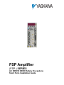
1
FSP Amplifier (FSP-) SERIES AC SERVO DRIVE Safety Precautions Short Form Installation Guide FSP Amplifier Short Form Installation Guide Introduction 2 FSP Amplifier Short Form Installation Guide Introduction 3 FSP Amplifier Short Form Installation Guide Introduction Copyright © 2006 by Yaskawa Electric America, Inc. FSP Amplifier Safety Precautions, Installation Guide (Short Form) YEA-SIA-FSP-2 Rev. C December, 2006 All rights reserved. No part of this publication may be stored in a retrieval system, or reproduced in any way, including but not limited to photocopy, photography, magnetic or other recording, without the prior agreement and written permission of the publisher. Program listings may be entered, stored and executed in a computer system, but not reproduced for publication. This guide is designed to provide information about the FS P Amplifier hardware. Every effort has been made to make this guide complete and as accurate as possible. However, no warranty of suitability, purpose or fitness is made or implied. Yaskawa Electric America, Inc. (YEA) is not liable or responsible to any person or entity for loss or damage in connection with or stemming from the use of the FS P Amplifier and/or the information contained in this publication YEA bears no responsibility for errors, which may appear in this publication and retains the right to make changes to the products and the guide without prior notice. Yaskawa Electric America, Inc. 2121 Norman Drive South Waukegan, IL 60085 United States Tel: 1-800-927-5292 Fax: 1-847-887-7310 [email protected] For more information refer to our web site: www.yaskawa.com 4 FSP Amplifier Short Form Installation Guide Introduction This page intentionally left blank. 5 FSP Amplifier Short Form Installation Guide Introduction T1. Introduction ..........................................................................................................8 1.1. Safety Precautions..........................................................................................9 1.2. Notes for Safe Operation..............................................................................10 1.3. Warning Label..............................................................................................16 1.4. Parts..............................................................................................................17 2. Checking Products On Delivery .......................................................................18 3. Appearance and Nameplate..............................................................................19 3.1. Type Designation .........................................................................................20 4. Installation..........................................................................................................21 4.1. Operating Conditions ...................................................................................21 4.2. Installation Sites ...........................................................................................21 4.3. Orientation ...................................................................................................22 4.4. M ultiple FSP Amplifier Installation ............................................................23 4.4.1 Where M ounted Side by Side ..............................................................23 4.4.2 Environment Inside Control Box.........................................................23 5. Wiring .................................................................................................................24 5.1. M olded-case Circuit Breaker and Fuse Capacity.........................................24 5.2. M ain Circuit Wiring.....................................................................................24 5.3. M ain Circuit Wire Size ................................................................................25 5.4. Typical M ain Circuit Wiring Examples .......................................................29 5.4.1. Single-phase 100 V/200 V M ain Circuit..............................................29 5.4.2. Single-phase 200 V 0.8 kW and 1.5 kW M ain Circuit ........................30 5.4.3. Three-phase 200 V M ain Circuit .........................................................31 5.4.4. Three-phase 400 V M ain Circuit .........................................................32 5.5. M ain Circuit Wiring Graphic Diagrams ......................................................33 5.5.1. Single-phase 100 V/200 V M ain Circuit..............................................33 5.5.2. Single-phase 200 V 0.8 kW and 1.5 kW M ain Circuit .......................34 5.5.3. Three-phase 200 V M ain Circuit .........................................................35 5.5.4. Three-phase 400 V M ain Circuit .........................................................36 5.6. AC Power Source Supply ............................................................................38 5.7. DC Power Source Supply ............................................................................38 5.8. Noise Control...............................................................................................38 6. Operation............................................................................................................39 6.1. Precautions at Test Run................................................................................39 6.2. Conducting Test Run for Servomotor Without Load...................................39 6.3. Conducting Test Run with Servomotor Connected to M achine ..................39 6.4. Precautions During Operation......................................................................40 7. Inspection and Maintenance .............................................................................41 7.1. FSP Amplifier Inspection.............................................................................41 7.2. Part Replacement Period..............................................................................42 7.3. Replacing the Battery for an Absolute Encoder...........................................42 7.3.1. Recommended Battery.........................................................................42 7.3.2. Replacing the Battery...........................................................................43 8. Installation Conditions of EMC Directive .......................................................44 8.1. EM C Installation Conditions .......................................................................44 8.1.1. Installation: Single & Three-phase 100/200 V FSP Amplifier (PC) ...44 8.1.2. Installation: Single & Three-phase 100/200 V FSP Amplifier (PLC) .45 8.1.3. Installation: Three-phase 400 V FSP Amplifier ..................................46 T 6 FSP Amplifier Short Form Installation Guide Introduction 8.2. Cable Core and Cable Clamp.......................................................................47 8.2.1. Cable Core............................................................................................47 8.2.2. Cable Clamp.........................................................................................47 9. Peripheral Devices..............................................................................................48 9.1. Peripheral Device Types and Capacities......................................................48 9.2. Noise Filter for Brake Power Supply...........................................................48 9.3. Cable Specifications.....................................................................................50 9.4. Recommended Ferrite Cores ........................................................................50 9.5. Shield Box....................................................................................................50 10. Overload Characteristics...............................................................................51 11. Appendix A .....................................................................................................52 11.1. I/O Signals Connector CN1 .....................................................................52 11.2. Encoder Connector CN2..........................................................................53 11.3. Serial Communication Connector CN3 ...................................................54 11.4. Analog M onitor Connector CN5..............................................................54 11.5. Connecting NON-Yaskawa M otor with A/B Encoder ............................55 11.6. Connecting Pulse A/B Encoder without C Pulse (Index Pulse)...............56 7 FSP Amplifier Short Form Installation Guide 1. Introduction Introduction This guide describes the FSP- series AC servo drive (FSP Amplifier) that controls Yaskawa Sigma II series or any compatible AC servomotor. This product conforms to the following standards: • EN61000-6-2: 1999 • EN55011: 1998, Group 1 Class A However, because this product is a built-in type, reconfirmation of the above standards is required after being installed in the final product. Upon receipt of the product and prior to installing the product, read these instructions carefully and retain for future reference. This will enable you to properly use the FSP Amplifier and carry out periodic inspection, maintenance, etc. Related documents: Title Catalog No. Sigma FSP Servo System User’s Manual YEA-SIA-FSP-3 AC Servo Motor Instructions for Yaskawa Sigma II series motors or documentation for other compatible motors TOE-C231-2 (for Sigma II) FlexWorks User's Manual YEA-SIA-FSP-4 Manufacturer’s motor specification This guide and other related documents can be downloaded from our website: www.yaskawa.com Note: YEA is not responsible for accidents or damages resulting from product modifications made by the user. 8 FSP Amplifier Short Form Installation Guide Introduction 1.1. Safety Precautions In this guide, safety precautions are classified as WARNING or CAUTION. It is extremely important that you pay close attention to these precautions. The following symbols are used: WARNING Indicates a potentially hazardous situation, which, if not avoided, could result in death or serious personal injury. CAUTION Indicates a potentially hazardous situation which, if not avoided, could result in minor or moderate personal injury and/or damage to the equipment. In some instances, items described in CAUTION could also result in a serious accident. Read the following safety precautions thoroughly before installation, operation, maintenance or inspection of the FSP Amplifier. 9 FSP Amplifier Short Form Installation Guide Introduction 1.2. Notes for Safe Operation WARNING • Never touch any rotating motor parts while the motor is running. Failure to observe this warning may result in injury. • Before starting operation with a machine connected, make sure that an emergency stop can be applied at any time. Failure to observe this warning may result in injury. • Never touch the inside of the FS P Amplifier. Failure to observe this warning may result in electric shock. • Do not remove the terminal cover while the power is ON. Failure to observe this warning may result in electric shock. • Do not touch terminals for five minutes after the power is turned OFF. Residual voltage may cause electric shock. • Do not touch terminals for five minutes after voltage resistance test. Residual voltage may cause electric shock. • Follow the procedures and instructions for trial operation precisely as notedin the relevant User's Manual. Malfunctions that occur after the servomotor is connected to the equipment not only damage the equipment, but may also cause an accident resulting in death or injury. • The multi-turn limit value must be changed only for special applications. Changing it inappropriately or unintentionally can be dangerous. • If the Multi-turn Limit Disagreement alarm occurs, check the setting of parameter Pn205 in the FS P Amplifier to be sure that it is correct. If Fn013 is executed when an incorrect value is set in Pn205, an incorrect value will be set in the encoder. The alarm will disappear even if an incorrect value is set, but incorrect positions will be detected, resulting in a dangerous situation where the machine will move to unexpected positions. • Do not remove the terminal cover, cables, connectors, or optional items while the power is ON. Failure to observe this warning may result in electric shock. • Connect the ground terminal to electrical codes (ground resistance: 100 Ω or less). Improper grounding may result in electric shock or fire. • Only authorized personnel must perform installation, disassembly, or repair. Failure to observe this warning may result in electric shock or injury. 10 FSP Amplifier Short Form Installation Guide Introduction WARNING • Do not damage, press and exert excessive force or place heavy objects on the cables. Failure to observe this warning may result in electric shock, stoppage of operation, or burning. • Do not modify the product. Failure to observe this warning may result in injury or damage to the product. • Provide an appropriate stopping device on the machine side to ensure safety. A holding brake for a servomotor with brake is not a stopping device for ensuring safety. Failure to observe this warning may result in injury. • Do not come close to the machine immediately after resetting momentary power loss to avoid an unexpected restart. Take appropriate measures to ensure safety against an unexpected restart. Failure to observe this warning may result in injury. Checking on Delivery CAUTION • Always use the servomotor and the FS P Amplifier in one of the specified combinations. Failure to observe this caution may result in fire or malfunction. Storage and Transportation CAUTION • Do not store or install the product in the following locations. Locations subject to direct sunlight. Locations subject to temperatures outside the range specified in the storage/installation temperature conditions. Locations subject to humidity outside the range specified in the storage/installation humidity conditions. Locations subject to condensation as the result of extreme changes in temperature. Locations subject to corrosive or flammable gases. Locations subject to dust, salts or iron dust. Locations subject to exposure to water, oil or chemicals. Locations subject to shock or vibration. Failure to observe this caution may result in fire, electric shock, or damage to the product. 11 FSP Amplifier Short Form Installation Guide • Introduction Do not hold the product by the cables or motor shaft while transporting it. Failure to observe this caution may result in injury or malfunction. • Do not place any load exceeding the limit specified on the packing box. Failure to observe this caution may result in injury or malfunction. • Do not hold the product by the eyebolt of motor while transporting it. Failure to observe this caution may result in injury or malfunction. Installation CAUTION • Never use the products in an environment subject to water, corrosive gases, inflammable gases, or combustibles. Failure to observe this caution may result in electric shock or fire. • Do not step on or place a heavy object on the product. Failure to observe this caution may result in injury. • Do not cover the inlet or outlet ports and prevent any foreign objects from entering the product. Failure to observe this caution may cause internal elements to deteriorate resulting in malfunction or fire. • Be sure to install the product in the correct direction. Failure to observe this caution may result in malfunction. • • Provide the specified clearance between the FS P Amplifier and the control panel or other device. Failure to observe this caution may result in fire or malfunction. Do not apply any strong impact. Failure to observe this caution may result in malfunction. 12 FSP Amplifier Short Form Installation Guide Introduction Wiring CAUTION • Do not connect a three-phase power supply to the U, V, or W output terminals. Failure to observe this caution may result in injury or fire. • • • S ecurely connect the power supply terminal screws and motor output terminal screws. Failure to observe this caution may result in fire. Do not bundle or run power and signal lines together in the same duct. Keep power and signal lines separated by at least 30 cm (11.81 in). Failure to observe this caution may result in fire. Use twisted-pair shielded wires or multi-core twisted pair shielded wires for signal and encoder (PG) feedback lines. The maximum length is 3 m (118. 11 in) for reference input lines and is 20 m (787.40 in) for PG feedback lines. If feedback lines are longer than 20 m (787.40 in), use the 50 m (1968.50 in) cable. • Do not touch the power terminals for 5 minutes after turning power OFF because high voltage may still remain in the FS P Amplifier. Make sure the charge indicator is out first before starting an inspection. • Avoid frequently turning power ON and OFF. Do not turn power ON or OFF more than once per minute. Since the FSP Amplifier has a capacitor in the power supply, a high charging current flows for 0.2 seconds when power is turned ON. Frequently turning power ON and OFF causes main power devices like capacitors and fuses to deteriorate, resulting in unexpected problems. • Observe the following precautions when wiring main circuit terminal blocks. Failure to observe this caution may result in injury, fire, or malfunction. Remove the terminal block from the FSP Amplifier prior to wiring. Insert only one wire per terminal on the terminal block. Make sure that the core wire is not electrically shorted to adjacent core wires. The leakage from the power lines may be extremely large for 400 V FSP Amplifier. Be sure to secure the wiring of the power lines. • Do not connect the FS P Amplifier for 100 V and 200 V directly to a voltage of 400 V. The FSP Amplifier will be destroyed. • Be sure to wire correctly and securely. Failure to observe this caution may result in motor overrun, injury, or malfunction. • Always use the specified power supply voltage. An incorrect voltage may result in burning. • Take appropriate measures to ensure that the input power supply is supplied within the specified voltage fluctuation range. Be particularly careful in places where the power supply is unstable. An incorrect power supply may result in damage to the product. • Install external breakers or other safety devices against short-circuiting in external wiring. Failure to observe this caution may result in fire. 13 FSP Amplifier Short Form Installation Guide Introduction CAUTION • Take appropriate and sufficient countermeasures for each when installing systems in the following locations. Failure to observe this caution may result in damage to the product. Locations subject to static electricity or other forms of noise. Locations subject to strong electromagnetic fields and magnetic fields. Locations subject to possible exposure to radioactivity. Locations close to power supplies. • Do not reverse the polarity of the battery when connecting it. Failure to observe this caution may damage the battery or cause it to explode. Operation CAUTION • Conduct trial operation on the servomotor alone with the motor shaft disconnected from machine to avoid any unexpected accidents. Failure to observe this caution may result in injury. • Before starting operation with a machine connected, change the settings to match the parameters of the machine. Starting operation without matching the proper settings may cause the machine to run out of control or malfunction. • Forward run prohibited (P-OT) and reverse run prohibited (N-OT) signals are not effective during zero point search mode using parameter Fn003. Failure to observe this caution may result in injury. • When using the servomotor for a vertical axis, install the safety devices to prevent workpieces to fall off due to occurrence of alarm or overtravel. S et the servomotor so that it will stop in the zero clamp state at occurrence of overtravel. Failure to observe this caution may cause workpieces to fall off due to overtravel. • When not using the online autotuning set to the correct moment of inertia ratio. Setting to an incorrect moment of inertia ratio may cause vibration. • • • • Do not touch the FS P Amplifier’s heat sink, regenerative resistor, or servomotor while power is ON or soon after the power is turned OFF. Failure to observe this caution may result in burns due to high temperatures. Do not make any extreme adjustments or setting changes of parameters. Failure to observe this caution may result in injury due to unstable operation. When an alarm occurs, remove the cause, reset the alarm after confirming safety, and then resume operation. Failure to observe this caution may result in injury. Do not use the servo brake of the servomotor for ordinary braking. Failure to observe this caution may result in malfunction. 14 FSP Amplifier Short Form Installation Guide Introduction Maintenance and Inspection CAUTION • Do not disassemble the FS P Amplifier. Failure to observe this caution may result in electric shock or injury. • Do not attempt to change wiring while the power is ON. Failure to observe this caution may result in electric shock or injury. • When replacing the FS P Amplifier, resume operation only after transferring the previous FS P Amplifier parameters to the new FS P Amplifier. Failure to observe this caution may result in damage to the product. Disposal CAUTION • When disposing of the products, treat them as ordinary industrial waste. Failure to observe this caution may result in injury. 15 FSP Amplifier Short Form Installation Guide Introduction 1.3. Warning Label The following illustration shows an example of the FSP Amplifier’s warning label. The mounting position of the label differs depending on the model and capacity of the FSP Amplifier. 16 FSP Amplifier Short Form Installation Guide Introduction 1.4. Parts The part names of the FSP Amplifier are shown in the following diagram: 17 FSP Amplifier Short Form Installation Guide 2. Checking Products On Delivery Checking Products On Delivery The following procedure is used to check FSP- series products upon delivery. Check Item Comments Are the delivered products the ones you ordered? Check the model numbers marked on the nameplates of the FSP Amplifier. Is there any visible damage? Check the overall appearance and check for damage or scratches that may have occurred during transportation. Are there any loose screws? Tighten any loose screws with a screwdriver. If any of the above items are faulty or incorrect, contact your local sales representative or the dealer from whom you purchased the product(s). 18 FSP Amplifier Short Form Installation Guide 3. Appearance and Nameplate Appearance and Nameplate 19 FSP Amplifier Short Form Installation Guide Appearance and Nameplate 3.1. Type Designation FSP - 05 D - MC Options - No options C - P re-load ed ECA M S - S ingl e-phas e a mpli fier (08 and 15 only ) Fl exib le S er voPack Max. Appli cable Servom otor Power (s ee table below) Input Voltage B - 100VAC , or A - 200VAC , or D - 400VAC Control Method MC - Serial MH - A-B quadrature Output Capacity Code Max. Applicable S ervomotor Power (kW) A3 A5 01 02 04 05 08 10 15 20 30 50 0.03 0.05 0.10 0.20 0.40 0.50 0.75 1.00 1.50 2.00 3.00 5.00 20 FSP Amplifier Short Form Installation Guide 4. Installation Installation The FSP Amplifier is a base-mount type servo controller. Incorrect installation will cause problems. Always observe the installation instructions provided below. 4.1. Operating Conditions Ensure the following operating conditions for the FSP Amplifier use: * Installation category (Overvoltage category)*: II Pollution degree* : 2 * Protection class : 1X M aximum altitude: 1000 m Conforming to the following standards: EN55011: 1198 Group 1 Class A EN61000-6-2: 1999 4.2. Installation Sites For installation sites, use proper care with the following notes. S ituation When installed inside a control panel Notes on Installation • Design the control panel size, unit layout, and cooling method so that temperature around the periphery of the FSP Amplifier does not exceed 55οC. • When installing multiple FSP Amplifiers side by side in a control panel, install cooling fans and provide sufficient space around each FSP Amplifier to allow cooling by fan and natural convection. When installed near a heating unit Suppress radiated heat from the heating unit and temperature rise caused by convection so that the temperature around the periphery of the FSP Amplifier does not exceeds 55οC. When installed near a vibration source Install a vibration isolator underneath the FSP Amplifier to prevent it from receiving vibration. When installed in a corrosive gases area Corrosive gases do not immediately affect the FSP Amplifier but will eventually cause contactor-related devices to malfunction. Take appropriate action to protect against corrosive gases. • Avoid installation in a hot and humid place or where excessive dust or iron powder is present in the air. Others • Be sure there is no condensation or freezing. • Keep the ambient temperature 45οC or less to ensure long-term reliability. 21 FSP Amplifier Short Form Installation Guide Installation 4.3. Orientation Install the FSP Amplifier perpendicular to the wall and orientate it as shown in the figure below. Firmly secure the FSP Amplifier through two or four mounting holes (depending on the FSP Amplifier capacity). Wall Ventilation 22 FSP Amplifier Short Form Installation Guide Installation 4.4. Multiple FSP Amplifier Installation FAN C N 3 C N 3 C N 3 C N 1 C N 1 C N 1 C N 1 C N 2 C N 2 C N 2 C N 2 50mm(2in.) or more C N 3 10mm(0.4in.)or more 30mm(1.2in.)or more or more FAN 50mm(2in.) When installing multiple FSP Amplifiers side by side in a control panel, observe the following: 30mm(1.2in.)or more 4.4.1 Where Mounted Side by Side When installing FSP Amplifiers side by side, provide at least 10 mm (0.4 in) space between them and at least 50 mm (2 in) space above and below them as shown in the figure above. Install cooling fans above the FSP Amplifiers to prevent the temperature around each FSP Amplifier from increasing excessively and also to maintain the temperature inside the control panel evenly. 4.4.2 Environment Inside Control Box M aintain the following conditions inside the control box: Ambient temperature for FSP Amplifier: 0 to 55οC Humidity: 90% RH or less, no condensing. 2 Vibration: 4.9 m/s No freezing. ο Ambient temperature to ensure long-term reliability: 45 C or less 23 FSP Amplifier Short Form Installation Guide 5. Wiring Wiring 5.1. Molded-case Circuit Breaker and Fuse Capacity Current Capacity of the Molded-case Circuit Breaker and the Fuse (Arms)*1, *2 Main Control circuit circuit Power Power Supply Supply Capacity (kW) FSP- Power Supply Capacity per FSP Amplifier (kVA) 0.03 0.05 0.10 0.20 0.03 0.05 0.10 0.20 0.40 A3B* A5B* 01B* 02B* A3A* A5A* 01A* 02A* 04A* 0.15 0.25 0.40 0.60 0.20 0.25 0.40 0.75 1.2 8 Singlephase 220V 0.75 08A* 2.1 11 1.50 15A* 4.0 19 Threephase 200V 2.00 20A* 4.3 13 3.00 30A* 5.9 17 Main circuit Power Supply Singlephase 100V Singlephase 200V FSP Amplifier model 4 Inrush current Main circuit Power Supply Control circuit Power Supply 0.26 32 A 30 A 0.13 63 A 60 A 0.13*4 130 A 66 A 0.13*4 63 A 60 A 6 4 0.50 05D* 1.1 1.6 10 A 1.00 10D* 2.3 3.4 Three1.50 15D* 3.2 4.6 *4 0.7 --*3 phase 2.00 20D* 4.9 7.1 400V 20 A 3.00 30D* 6.7 9.7 5.00 50D* 10.3 14.9 78 A *1. Nominal value at rated load. The specified derating is required to select an appropriate fuse capacity. *2. Cutoff characteristics (25°C): 300% five seconds min. and inrush current of 20ms. *3. A preventive circuit for inrush current is not built in the 24 VDC control power supply. Customer must design the protective circuit. *4. Make sure the current capacity is accurate. For an FSP Amplifier with cooling fan built-in, an inrush current flows; 200% of the current capacity (in the table above) for two seconds, when turning ON the control circuit. 5.2. Main Circuit Wiring FSP Amplifiers are suitable under the following conditions. With 100 V class: Less than 5000 A rms, 120 V maximum. With 200 V class: Less than 5000 A rms, 240 V maximum. With 400 V class: Less than 5000 A rms, 480 V maximum. FSP Amplifiers must be used with UL-listed fuses or circuit breakers, in accordance with the National Electrical Code (NEC). Use 75οC heat-resistant copper wires or an equivalent. 24 FSP Amplifier Short Form Installation Guide Wiring 5.3. Main Circuit Wire Size Cable Types S ymbol PVC IV HIV • • • • • • Allowable Conductor Temperature ºC (ºF) Cable Types Name Normal vinyl cable — 600V vinyl cable 60 (140) Temperature-resistant vinyl cable 75 (167) Wire sizes are selected for three cables per bundle at 40°C (104°F) ambient temperature with the rated current. Use cable with a minimum withstand voltage of 600V for main circuits. If cables are bundled in PVC or metal ducts, consider the reduction ratio of the allowable current. Use heat-resistant cables under high ambient or panel temperatures where normal vinyl cables will rapidly deteriorate. Use cables within the allowable moment of inertia. Do not use cables under continuous regenerative state. The following table shows the wire size and allowable current for three cables. Use a cable whose specifications meet or are less than the values in the table. 600-V Heat-resistant Vinyl Cables (HIV) AWG Size 20 — 18 16 14 12 10 8 6 4 Nominal Configuration Conductive Allowable Current at Ambient Cross Temperature Number of Resistance 2 Section 30°C wires/mm 40°C 50°C Ω/km 2 Diameter (in ) (86°F) (104°F) (122°F) mm2 (in2) 0.5 (0.00078) 19/0.18 (0.00028) 39.5 6.6 5.6 4.5 0.75 (0.00116) 30/0.18 (0.00028) 26.0 8.8 7.0 5.5 0.9 (0.00140) 37/0.18 (0.00028) 24.4 9.0 7.7 6.0 1.25 (0.00193) 50/0.18 (0.00028) 15.6 12.0 11.0 8.5 2.0 (0.00310) 7/0.6 (0.00093) 9.53 23 20 16 3.5 (0.00543) 7/0.8 (0.00124) 5.41 33 29 24 5.5 (0.00853) 7/1.0 (0.00155) 3.47 43 38 31 8.0 (0.01240) 7/1.2 (0.00186) 2.41 55 49 40 14.0 (0.02170) 7/1.6 (0.00248) 1.35 79 70 57 22.0 (0.03410) 7/2.0 (0.00310) 0.85 91 81 66 Note: The values in the table are for reference only. 25 FSP Amplifier Short Form Installation Guide Wiring Main Circuit Input Terminals (L1, L2, L3), Servomotor Connection Terminals (U, V, W) Main Circuit Power Supply Singlephase 100V Singlephase 200V Singlephase 220V Threephase 200V Threephase 400V Model Capacity (kW) FSP0.03 0.05 0.10 0.20 0.03 0.05 0.10 0.20 0.40 A3B* A5B* 01B* 02B* A3A* A5A* 01A* 02A* 04A* 0.75 08A* 1.50 15A* 2.00 20A* 3.00 0.50 1.00 1.50 2.00 3.00 5.00 30A* 05D* 10D* 15D* 20D* 30D* 50D* Servomotor Connection Terminals (U, V, W) Wire Type Terminal Tightening Wire Type Terminal Tightening & Size Screw Torque & Size Screw Torque (mm2 ) Size (N·m) (mm2 ) Size (N·m) Main Circuit Input Terminals (L1, L2, L3)*1 HIV l.25 — — HIV 1.25 — — — — HIV 1.25 — — HIV 2.0 — — HIV 1.25 — — HIV 3.5 M4 1.2 to 1.4 HIV 2.0 M4 1.2 to 1.4 HIV 3.5 M4 1.2 to 1.4 M4 1.2 to 1.4 HIV 1.25 — — HIV 1.25 — — HIV 2.0 M4 1.2 to 1.4 HIV 2.0 M4 1.2 to 1.4 HIV 3.5 M5 1.6 to 2.4 HIV 3.5 M5 1.6 to 2.4 HIV 2.0 HIV 1.25 HIV 2.0 HIV 3.5 HIV 5.5 *1. Connect the main power supply to terminals L1 and L3 for FSP-08A*-S and FSP-15A*-S. Do not connect to the L2 terminal. 26 FSP Amplifier Short Form Installation Guide Wiring Control Power Input Terminals (L1C, L2C), External Regenerative Resistor Terminals (B1, B2) Main Circuit Power Supply Singlephase 100V Singlephase 200V Singlephase 220V Threephase 200V Threephase 400V Model Capacity (kW) FSP0.03 0.05 0.10 0.20 0.03 0.05 0.10 0.20 0.40 A3B* A5B* 01B* 02B* A3A* A5A* 01A* 02A* 04A* 0.75 08A* 1.50 15A* 2.00 20A* 3.00 0.50 1.00 1.50 2.00 3.00 5.00 30A* 05D* 10D* 15D* 20D* 30D* 50D* External Regeneration Resistor Terminals (B1, B2) Wire Type Terminal Tightening Wire Type Terminal Tightening & Size Screw Torque & Size Screw Torque (mm2 ) Size (N·m) (mm2 ) Size (N·m) Main Circuit Input Terminals (L1C, L2C)*1 HIV l.25 — — HIV1.25 — — HIV 1.25 — — HIV1.25 — — — — — — M4 1.2 to 1.4 M4 1.2 to 1.4 M4 1.2 to 1.4 M4 1.2 to 1.4 — — — — M4 1.2 to 1.4 HIV 1.25 HIV 1.25 HIV1.25 HIV2.0 HIV3.5 HIV1.25 HIV 1.25 M4 1.2 to 1.4 HIV2.0 *1. Terminal symbols +24 V and 0 V are for 3-phase 400V FSP Amplifiers only. 27 FSP Amplifier Short Form Installation Guide • Ground Terminal Main Circuit Power Supply Singlephase 100V Singlephase 200V Singlephase 220V Threephase 200V Threephase 400V • Wiring Capacity (kW) Model FSP- 0.03 0.05 0.10 0.20 0.03 0.05 0.10 0.20 0.40 0.75 A3B* A5B* 01B* 02B* A3A* A5A* 01A* 02A* 04A* 08A* 1.50 15A* 2.00 20A* 3.00 30A* 0.50 1.00 1.50 2.00 3.00 5.00 05D* 10D* 15D* 20D* 30D* 50D* Ground Terminal Wire Type & Terminal Size Screw (mm2 ) Size Tightening Torque (N·m) HIV 2.0 or larger M4 1.2 to 1.4 HIV 2.0 or larger M4 1.2 to 1.4 HIV 2.0 or larger M4 1.2 to 1.4 HIV 2.0 or larger M4 1.2 to 1.4 M4 1.2 to 1.4 M5 1.6 to 2.4 HIV 2.0 or larger S ignal Line Wire S izes The following table shows appropriate cables for CN1 and CN2 FSP Amplifier connectors. Wire sizes were selected for three cables per bundle at 40ºC ambient temperature with the rated current. Connector Name and S ignal Control I/O Signal Connector PG Signal Connector CN1 CN2 Item Cable Applicable wire Finished cable dimension Cable Applicable wire Finished cable dimension S pecification Twisted-pair or shielded twisted-pair wire. AWG24 (0.2 mm2 ), AWG26 (0.12 mm2 ), AWG28 (0.08 mm2 ), AWG30 (0.05 mm2 ). Ø 16.0 mm (Ø 0.63 in) MAX. Shielded twisted-pair wire. AWG 24 (0.2 mm2 ), AWG 26 (0.12 mm2 ), AWG 28 (0.08 mm2 ), AWG 30 (0.05 mm2 ). Use AWG 22 (0.33 mm2 ) for encoder power supply and AWG 26 (0.12 mm2 ) for other signals. These conditions permit wiring distances up to 20 m (65.6 ft). Ø 6.8 mm (Ø 0.27 in) MAX. 28 FSP Amplifier Short Form Installation Guide Wiring 5.4. Typical Main Circuit Wiring Examples Only qualified personnel should perform the wiring. Design the circuit so that the main circuit power supply turns OFF at emergency stop. 5.4.1. Single-phase 100V/200V Main Circuit FSP Amplifier 1QF : M olded-case circuit breaker FIL : Noise filter 1KM : M agnetic contactor 1Ry : 1PL : 1SUP : 1D : Relay Indicator lamp Surge suppressor Flywheel diode *1. T hese circuits are power lines. Do not touch these terminals when the power is ON to avoid electric shock. *2. T hese circuits are SELV circuits and are separated from all other circuits by double and reinforced insulation. T he CN1 input signal is available for sink or source circuits. Note : Customers must purchase a 24VDC power supply with a doubleshielded enclosure. 29 FSP Amplifier Short Form Installation Guide 5.4.2. Wiring Single-phase 200V 0.8kW and 1.5kW Main Circuit FSP Amplifier 1QF : M olded-case circuit breaker FIL : Noise filter 1KM : M agnetic contactor 1Ry : 1PL : 1SUP : 1D : Relay Indicator lamp Surge suppressor Flywheel diode *1. T hese circuits are power lines. Do not touch these terminals when the power is ON to avoid electric shock. *2. T hese circuits are SELV circuits and are separated from all other circuits by double and reinforced insulation. T he CN1 input signal is available for sink or source circuits. Note : Customers must purchase a 24 VDC power supply with a doubleshielded enclosure. 30 FSP Amplifier Short Form Installation Guide 5.4.3. Wiring Three-phase 200V Main Circuit FSP Amplifier 1QF : M olded-case circuit breaker FIL : Noise filter 1KM : M agnetic contactor 1Ry : 1PL : 1SUP : 1D : Relay Indicator lamp Surge suppressor Flywheel diode *1. T hese circuits are power lines. Do not touch these terminals when the power is ON to avoid electric shock. *2. T hese circuits are SELV circuits and are separated from all other circuits by double and reinforced insulation. T he CN1 input signal is available for sink or source circuits. Note : Customers must purchase a 24VDC power supply with a doubleshielded enclosure. 31 FSP Amplifier Short Form Installation Guide 5.4.4. Wiring Three-phase 400V Main Circuit FSP Amplifier 1QF : M olded-case circuit breaker FIL : Noise filter 1KM : M agnetic contactor 1Ry : 1PL : 1SUP : 1D : Relay Indicator lamp Surge suppressor Flywheel diode *1. T hese circuits are power lines. Do not touch these terminals when the power is ON to avoid electric shock. *2. T hese circuits are SELV circuits and are separated from all other circuits by double and reinforced insulation. T he CN1 input signal is available for sink or source circuits. Note : Customers must purchase a 24VDC power supply with a doubleshielded enclosure. 32 FSP Amplifier Short Form Installation Guide Wiring 5.5. Main Circuit Wiring Graphic Diagrams 5.5.1. Single-phase 100V/200V Main Circuit Personal Computer Cable type P/N: YS-12 Host Controller FSP Amplifier is compatible with most PLC motion controllers and indexers. Used for a servomotor with a brake. 33 FSP Amplifier Short Form Installation Guide 5.5.2. Wiring Single-phase 200V 0.8kW and 1.5kW Main Circuit Observe the following points. 1. Connect main power supply shown below to L1 and L3 terminals. Power supply is single-phase, 220 to 230VAC +10% to -15%, 50/60Hz. If power supply of 187 V (-15% of 220V) or less is used, alarm A.41 indicating voltage shortage, may occur when accelerating to max speed with max torque of motor. 2. Short-circuit B2 and B3 terminals using the internal regenerative resistor. If capacity of the regenerative resistor is insufficient, remove the lead between B2 and B3 terminals and connect an external regenerative resistor unit to B1 and B2 terminals. Personal Computer Cable type P/N: YS-12 Host controller FSP Amplifier is compatible with most PLC motion controllers and indexers. Used for a servomotor with a brake. 34 FSP Amplifier Short Form Installation Guide 5.5.3. Wiring Three-phase 200V Main Circuit Personal Computer Cable type: P/N YS-12 Host controller FSP Amplifier is compatible with most PLC motion controllers and indexers. Used for a servomotor with a brake. 35 FSP Amplifier Short Form Installation Guide 5.5.4. Wiring Three-phase 400V Main Circuit Personal computer Cable type: P/N YS-12 Host controller FSP Amplifier is compatible with most PLC motion controllers and indexers. Used for a servomotor with a brake. 36 FSP Amplifier Short Form Installation Guide • • • • • • Wiring In conformance with local electrical codes, ground the FSP Amplifier grounding terminal (grounding resistance: 100 Ω or less). Be sure to connect the grounding wire of the servomotor to of the FSP Amplifier. Never share the grounding cable or main grounding point with welding equipment, power equipment or other high-voltage devices. Separate the grounding cable from wiring of high-voltage equipment. M ake the grounding wire as short as possible. If two or more FSP Amplifiers are used, ground them as shown in (a) below. Avoid methods (b) and (c). 37 FSP Amplifier Short Form Installation Guide Wiring 5.6. AC Power Source Supply Use the FSP Amplifier AC power source supply according to product ratings. See the following table for details. Power SinglePhase 200V ThreePhase 200V ThreePhase 400V FS P Amplifier Motor Output FSP-A3A* to FSP-04A* 30, 50, 100, 200, and 400W FSP-08A* and FSP-15A* 750 W and 1.5kW FSP-10A* to FSP-30A* 1.0, 2.0, and 3.0kW FSP-05D* to FSP-50D* 0.5, 1.0, 1.5, 2.0, 3.0 and 5.0kW S pecifications 1-phase 200VAC to 230VAC (+10% to -15%), 50/60 Hz 1-phase 220VAC to 230VAC *1 (+10% to -15%), 50/60 Hz 1-phase 200VAC to 230VAC (+10% to -15%), 50/60 Hz 3-phase 220VAC to 230VAC (+10% to -15%), 50/60 Hz Connection Terminals L1, L2 (Main) LIC, L2C (Control) L1, L3 (Main) L1C, L2C (Control) L1, L2, L3 (Main) 1-phase 200VAC to 230VAC (+10% to -15%), 50/60 Hz L1C, L2C (Control) 3-phase 380VAC to 480VAC (+10% to -15%), 50/60 Hz L1, L2, L3 (Main) DC power supply +24V (±15%) (not provided by YET) 24 V, 0 V (Control) *1. When a power supply of 187V (-15% of 220V) or less is used, alarm A.41, indicating voltage shortage, may occur when accelerating to max speed with max torque of servomotor. 5.7. DC Power Source Supply 3-Phase 400V FSP Amplifier models require 24VDC for its control circuit. The user must provide a 24VDC ± 15% power supply with a current capacity of at least 1 Amp. This power supply must also be able to withstand a surge of up to 3A for 50ms. It should be connected to the terminals marked 24V and 0V on the FSP Amplifier. WARNING • Do not connect AC voltage to these terminals. Doing so may cause permanent damage to the amplifier. 5.8. Noise Control • • • • If the signal line is affected by noise, malfunction may result. Separate power cables from control cables. M ake the signal line as short as possible and use twisted-pair wires. Never use a line filter (for power input) for servomotor circuit. If peripheral devices malfunction due to the noise from the FSP Amplifier, insert a line filter (for output, type LF-310KA, made by Tokin Corp.) between the servomotor and the FSP Amplifier. 38 FSP Amplifier Short Form Installation Guide 6. Operation Operation This section describes precautions that should be taken at test run and during operation. For instructions on test run and operation, refer to the Sigma FSP Servo System User’s M anual (Document # YEA-SIA-FSP-3). 6.1. Precautions at Test Run CAUTION • To avoid accidents, run the servomotor only in test run (without load). Failure to observe this caution could result in personal injury. • Before starting operation with a load connected, set up user constants suitable for the machine. Failure to do so could result in overrun failure. When the load moves vertically, incorrect setting of the user constants could cause the load to fall. • Before starting operation with a load connected, make sure emergencystop procedures are in place. Failure to observe this caution could result in personal injury. 6.2. Conducting Test Run for Servomotor Without Load When the servomotor is operated without a load, set the speed loop gain (user constant Pn100) to 40 or less. (The factory setting is 40.) The speed loop gain (user constant Pn100) is determined by: Load inertia ≥ (servomotor inertia × N) where 1 ≤ N ≤ 3. Therefore, if the servomotor is rotated without a load (i.e., without load inertia) or if the load inertia is small, the servomotor may oscillate. To avoid this possibility, set the value of Pn100 (speed loop gain) to 40 or less and then switch servo ON. 6.3. Conducting Test Run with Servomotor Connected to Machine Initial parameters for the FSP Amplifier are set assuming normal operation conditions. Before conducting a test run, set up user constants suitable for the machine. Failure to do so could result in machine overrun or breakdown. For the setting procedures and methods, refer to the Sigma FSP Servo System User’s M anual (Document # YEA-SIA-FSP-3). The following items should be checked during the test run: • Unusual vibration • Abnormal noise • Excessive temperature rise 39 FSP Amplifier Short Form Installation Guide Operation 6.4. Precautions During Operation CAUTION • During operation, do not touch the FS P Amplifier's heat sink. Failure to observe this caution could result in burns. • Motor overload protection is provided internally. Refer to the S igma FS P S ervo S ystem User’s Manual (Document # YEA-S IA-FS P-3) for rating. 40 FSP Amplifier Short Form Installation Guide 7. Inspection and Maintenance Inspection and Maintenance This section describes the basic inspection and maintenance procedures for the FSP Amplifier and battery replacement for absolute encoder. If any failure occurs on the FSP Amplifier, refer to the Sigma FSP Servo System User’s M anual (Document # YEA-SIA-FSP-3), Troubleshooting. Contact your YEA representative if the problem persists. WARNING • Be sure to turn OFF power before inspection or maintenance. Failure to observe this warning could result in electric shock. • Never open the terminal cover while power is ON, and never turn ON power when the terminal cover is open. Failure to observe this warning could result in electric shock. • After turning OFF power, wait at least five minutes before servicing the product. Otherwise, residual electric charges could result in electric shock. CAUTION • Never change wiring while power is ON. Failure to observe this caution could result in electric shock or personal injury. 7.1. FSP Amplifier Inspection The inspection and maintenance procedures listed in the table below should be performed at least once every year. Item Frequency Procedure Clean unit interior and circuit boards At least once per year Check for dust, dirt and oil on surfaces. Clean with compressed air if necessary. Loose screws At least once per year Check for loose terminal block and connector screws. Tighten any loose screws. Defective parts in unit or on circuit boards At least once per year Check for discoloration or damage due to heating. Contact your YEA representative. 41 Remedy FSP Amplifier Short Form Installation Guide Inspection and Maintenance 7.2. Part Replacement Period The following parts are subject to mechanical wear or deterioration over time. To avoid failure, replace these parts at the frequency indicated. If the FSP Amplifier has been repaired at YEA, its parameters will be set back to standard settings at shipment. Always check parameters before operating the servomotor. Part S tandard Replacement Period Cooling Fan 4 to 5 years Smoothing Capacitor 7 to 8 years Relays — Fuse 10 years Electrolytic Capacitor on Circuit Board 5 years Replacement Method Operating Conditions • Ambient temperature: Test. Replace with new part if annual average necessary. 30ºC Test. Replace if necessary. • Load factor: Replace with new part. 80% max. • Operation rate: Test. Replace with new 20 hours/day circuit board if necessary. max. Replace with new part 7.3. Replacing the Battery for an Absolute Encoder Battery replacement is only required for servo systems using an absolute encoder. When battery voltage is 2.7 V or less, the FSP Amplifier outputs an absolute encoder battery alarm (A.83, when using Yaskawa Sigma II motors with an absolute encoder) only when the FSP Amplifier's power is ON, but not while the FSP Amplifier is operating. 7.3.1. Recommended Battery Lithium battery: ER3V, manufactured by Toshiba Battery Co. Ltd., 3.6 V 1000 mAh or other compatible lithium battery. Battery kit (battery with connector) for Absolute Encoder Cable Adapter or wiring into CN1: JZSP-BA01 Battery kit (battery with connector) for wiring into CN1: JZSP-BA01-1 For wiring into CN1, refer to the Sigma FSP Servo System User’s M anual (Document # YEA-SIA-FSP-3), Absolute Encoder Battery. Note: The JZSP-BA01-1 has leads 3 cm longer than the JZSP-BA01. 42 FSP Amplifier Short Form Installation Guide 7.3.2. Inspection and Maintenance Replacing the Battery 1. With the FSP Amplifier's control power turned ON, replace the old battery with a new one. 2. Turn OFF the FSP Amplifier's control power to clear the absolute encoder battery alarm (A.83). 3. Turn ON the FSP Amplifier's control power. 4. M ake sure that FSP Amplifier is operating normally after power is turned on. Battery replacement is now completed. After replacing the battery, initialize the absolute encoder. Refer to the Sigma FSP Servo System User's M anual (Document # YEA-SIA-FSP-3), Initializing of Absolute Encoder. 43 FSP Amplifier Short Form Installation Guide 8. Installation Conditions of EMC Directive Installation Conditions of EMC Directive The following conditions must be satisfied for a combination of servomotor and the FSP Amplifier to comply with EM C Directives (EN61000-6-2 and EN55011, Group 1 Class A). 8.1. EMC Installation Conditions This section describes the test installation conditions prepared by YEA that meet EM C guidelines for all FSP Amplifier models. The actual EM C level may differ depending on the actual system’s configuration, wiring and other conditions. 8.1.1. Installation: Single & Three-phase 100/200V FSP Amplifier (PC) FSP-A3A* to -30A*(30W to 3.0kW) Represents option with PC connected to CN3 connector. Note: S hielded Box with door closed Cable length approx. 5m CORE 3 CORE CN1 2 1 CO RE CN3 PE CLAMP CLAMP CN2 CORE L1C , L2C CORE 4 NOIS E FILTE R CORE L1, L2 U, V, W FSP Amp CLAMP AC Po wer Supply Single- phase 200V or Three-phase 200V 50/60Hz Br ake Power Supply CORE NOISE FILTER Mains Cable Length Approx. 2m CLAMP Ground Plate/ Shielded Box BRAKE MOTOR ENCODER Personal Computer Cable length approx. 3m S ymbol Cable Name S pecification PC communication cable Shielded cable Servomotor cable Shielded cable Encoder cable Shielded cable AC line cable Shielded cable 44 PE FSP Amplifier Short Form Installation Guide 8.1.2. Installation Conditions of EMC Directive Installation: Single & Three-phase 100/200V FSP Amplifier (PLC) FSP-A3A* to -30A*(30W to 3.0kW) Represents option with PLC or controller connected to CN1 connector. Note: S hielded Box with door closed Cable length approx. 5m Brake Power Supply CORE NOISE FILTER Mains Cable Length Approx. 2m CLAMP Ground Plate/ Shielded Box CN 3 CORE 2 CORE L1C, L2C CLAMP CLAMP NOISE FILTER CORE W U, V, L1, L2 CLAMP AC Power Supply Single-phase200V or Three-phase200V 50/60Hz 4 CORE FSP FSPAmplifier Amp BRAKE MOTO R ENCODER CORE PE 1 CORE PLC or Controller CN3 PE CN PSU Cable length approx. 3m S ymbol Cable Name S pecification PLC communication cable Shielded cable Servomotor cable Shielded cable Encoder cable Shielded cable AC line cable Shielded cable 45 FSP Amplifier Short Form Installation Guide 8.1.3. Installation Conditions of EMC Directive Installation: Three-phase 400 V FSP Amplifier FSP-10D* to -30D* (0.5 kW to 3.0 kW) Represents option with PLC or controller connected to CN1 connector or PC connected to CN3 connector. Note: S hielded Box with door closed Cable length approx. 5m CORE PE 1 CORE PLC or Controll CN1 CN3 CORE CLAMP CORE PSU CORE CN2 3 CORE L1, L2, L3 2 1 MOTOR ENCODER CORE NOISE FILTER CLAMP CLAMP 4 24V, 0V U, V, W CLAMP Power Supply Three phase 400VAC BRAKE FSP Amplifier Power Supply 24VDC Mains Cable Length Approx. 2m CORE 5 Brake Power Supply NOISE FILTER CORE Power Supply Single phase 200VAC CLAMP Ground Plate/ Shielded Box PE Personal Computer Cable length approx. 3m Cable length approx. 3m Represents option with PLC or controller connected to CN1 connector. S ymbol Cable Name S pecification PLC, Controller or PC communication cable Shielded cable Servomotor cable Shielded cable Encoder cable Shielded cable AC line cable Shielded cable AC line cable Shielded cable 46 FSP Amplifier Short Form Installation Guide Installation Conditions of EMC Directive 8.2. Cable Core and Cable Clamp 8.2.1. Cable Core Attach the core on the cable as shown in the diagram below, which shows two turns of the cable: Cable Core The table below lists the cable names and the mounting positions of the core: Cable Name 8.2.2. Core Mounting Position Controller cable Near the Controller and the FSP Amplifier. Servomotor cable Near the FSP Amplifier and the servomotor. Encoder cable Near the FSP Amplifier and the servomotor. Cable Clamp Fix and ground the cable shield using a piece of conductive metal. The figure below shows an example of a cable clamp, controller side. FSP Amplifier Side Cable Shield Remove Cable Sheath Cable Ground plate Clamp Remove paint frommounting surface 47 FSP Amplifier Short Form Installation Guide 9. Peripheral Devices Peripheral Devices 9.1. Peripheral Device Types and Capacities The following table gives examples of peripheral devices for use with Yaskawa or other compatible motors. Main Model Circuit Power Supply Capacity FSP(kW) 0.10 A3B * A5B * 01B * 0.20 02B * 0.03 Singlephase 100 V 0.05 0.03 0.05 Singlephase 200 V 0.10 0.20 0.40 0.75 1.5 Threephase 200 V 1.0 2.0 3.0 0.45 1.0 Threephase 400 V 1.5 2.0 3.0 5.0 A3A * A5A * 01A * 02A * 04A * 08A * 15A * 10A * 20A * 30A * 05D * 10D * 15D * 20D * 30D * 50D * Power Supply MCCB or Capacity per Fuse FSP Amplif ier Capacity *1 (kVA) (A rms) Recommended Noise Filter *2 Model Specif ications Magnetic Contactor Current (A) 0.15 0.25 4 FN2070-6/07 Single-phase 250 VAC, 6A 20 0.40 0.60 6 FN2070-10/07 Single-phase 250 VAC, 10A 4 FN2070-6/07 Single-phase 250 VAC, 6A 0.2 0.25 0.40 20 0.75 1.2 8 2.1 11 4.0 19 2.3 7 4.3 13 5.9 13 1.2 1.7 2.3 3.4 3.2 4.6 4.9 7.1 6.8 9.8 10.3 14.9 Single-phase 250 VAC, 10A Single-phase FN2070-16/07 250 VAC, 16 A Single-phase FN350-30/33 250 VAC, 30 A FN2070-10/07 20 35 FN258L-16/07 Three-phase 480VAC, 16A 35 FN258L-30/07 Three-phase 480VAC, 30A 35 FN258L-7/07 Three-phase 480 VAC, 7 A 35 FN258L-16/07 Three-phase 480 VAC, 16 A 35 FS5559-35-33 Three-phase 480 VAC, 35 A 50 *1. This is net value for rated load. When selecting fuses, determine the capacity using the prescribed derating. Braking characteristics at 25°C: 200% for 2 seconds minimum; 700% for 0.01 second minimum. *2. The FN type noise filter is manufactured by Schaffner. 9.2. Noise Filter for Brake Power Supply The table below shows the recommended noise suppression filters models: 48 FSP Amplifier Short Form Installation Guide Peripheral Devices Circuit Filter model Manufacturer Brake power circuit FN2070-6/X*3 or FMW2-52-6/07 Schaffner or Timonta *3 Replace X with connection type: 07 = wire, 06 = for soldering or fast-on. 49 FSP Amplifier Short Form Installation Guide Peripheral Devices 9.3. Cable Specifications Shield cables should be used for the following cables: • • • • AC power input line cable (between power supply and noise filter) Servomotor cable (between FSP Amplifier and servomotor) Encoder cable (between FSP Amplifier and servomotor) Controller cable (between FSP Amplifier and controller) 9.4. Recommended Ferrite Cores Cable Manufacturer Encoder Cable Absolute Power Cable Serial 30W to 400W 0.8kW to 5kW Tokin Corp. ESD-SR-25 ESD-SR-25 ESD-SR-25 — Fair-Rite Corp. 0444173551 0444164181 0444173551 — TDK Corp. — — — PC40T96x20x70 9.5. Shield Box A shield box, a closed metallic enclosure, should be used for shielding from electromagnetic interference. The structure of the box should allow the main body, door, cooling unit etc. to be attached to the ground. The box opening should be as small as possible. 50 FSP Amplifier Short Form Installation Guide Overload Characteristics 10. Overload Characteristics The FSP Amplifier has a built-in overload protective function that protects the amplifier-motor pair from overload. Allowable power for the FSP Amplifier is limited by the overload protective function as shown in the figure below. The overload detection level is set under hot start* conditions at a servomotor ambient temperature of 40ºC (104ºF). * A hot start indicates that both the FSP Amplifier and servomotor have run long enough at the rated load to be thermally saturated. Note: The overload protection characteristics of A and B in the figure are applicable when the FSP Amplifier is combined with one of the following Yaskawa servomotors: A: SGM AH or SGM PH servomotor with capacity of maximum 400W. B: SGM AH or SGM PH servomotors with a capacity more than 400W and SGM GH, SGM SH, SGM DH and SGM UH servomotors. 51 FSP Amplifier Short Form Installation Guide Appendix A 11. Appendix A 11.1. I/O Signals Connector CN1 CN1 connector is required to connect the host controller to the FSP Amplifier. It comprised of a connector and a connector cover. Mating 50-Pin Connector Model (Kit) YEA P/N Connector Connector Parts 10150-3000VE * 4J4003 Case 10350-52A0-008 * * M anufactured by Sumitomo 3M Co. Terminal Layout Pin No. Name Pin No. Name 1 2 3 4 5 6 7 8 9 10 11 12 13 14 15 16 17 18 19 20 21 22 23 24 25 Signal Ground Signal Ground PL1 SEN V-REF Signal Ground PULS /PULS T -REF Signal Ground SIGN /SIGN PL2 /CLR CLR T MON VT G PL3 PCO /PCO BAT + BAT NC* NC* /V-CMP+ (out 1+) 26 27 28 29 30 31 32 33 34 35 36 37 38 39 40 41 42 43 44 45 46 47 48 49 50 /V-CMP- (out 1-) /T GON+ (out 2+) /T GON- (out 2-) /S-RDY+ (out 3+) /S-RDY- (out 3-) ALM+ (out 4+) ALM- (out 4-) PAO /PAO PBO /PBO ALO1 ALO2 ALO3 /S-ON /P-CON P-OT N-OT /ALM-RST /P-CL /N-CL +24V IN PSO /PSO NC* Note: NC – Leave contact open (Not Connected) 52 FSP Amplifier Short Form Installation Guide Appendix A 11.2. Encoder Connector CN2 Mating 20-Pin Connector Model Connector YEA P/N Connector Parts 4J4001 10120-3000VE* 4J0101 Cover * M anufactured by Sumitomo 3M Co. 10320 - 52A0-008* Terminal Layout Pin No. 1 2 3 4 5 6 7 8 9 10 Name Pin No. PG GND PG GND PG GND PG +5V PG +5V PG +5V NC* PS /PS Serial PG +5V 11 12 13 14 15 16 17 18 19 20 Name Serial PG GND BAT + BAT PC /PC PA /PA PB /PB NC* Note: NC – Leave contact open (Not Connected) Terminal Layout for Encoder Connector with Commutation Sensors (Optional) Pin No. 1 2 3 4 5 6 7 8 9 10 Nam e Pin No. PG GND PG GND PG GND PG +5V PG +5V PG +5V /UIN NC* /VIN Serial PG +5V 11 12 13 14 15 16 17 18 19 20 Note: NC – Leave contact open (Not Connected) 53 Nam e Serial PG GND BAT+ BATPC /PC PA /PA PB /PB /WIN FSP Amplifier Short Form Installation Guide Appendix A 11.3. Serial Communication Connector CN3 Mating 14-Pin Connector Model YEA P/N 4J4002 Connector Parts 10114-3000VE* Connector 4J0102 Cover * M anufactured by Sumitomo 3M Co. 10314-52A0-008* Terminal Layout Pin No. Name Pin No. 1 2 3 4 5 6 7 T XD /T XD RXD /RXD NC* /RXD RT (termination resistor) 8 9 10 11 12 13 14 Name T XD /T XD RXD NC* NC* +5V GND Note: NC – Leave contact open (Not Connected) 11.4. Analog Monitor Connector CN5 Mating 4-Pin Connector Model YEA P/N Model 4J7004 Socket DF11-4DS-2C* 4J0414 Pin DF11-EP2428SCA* * M anufactured by Hirose Electric Co. Mating Cable Model YEA P/N Model 4W1003 DE9404559* * M anufactured by Yaskawa Electric Co. Terminal Layout Pin No. Wire Color Name 1 2 3 4 Red White Black Black Analog Monitor 2 Analog Monitor 1 GND GND 54 FSP Amplifier Short Form Installation Guide Appendix A 11.5. Connecting NON-Yaskawa Motor with A/B Encoder Encoder cable (made by customer) FS P Amplifier S ide Pin Number (20-pin connector) 1,2,3 4,5,6,10 14 15 16 17 18 19 FG S ignal Name Remarks PG GND PG +5V PC /PC PA /PA PB /PB Connector Shield — Twisted Pair 55 Twisted Pair Twisted Pair Twisted Pair — FSP Amplifier Short Form Installation Guide Appendix A 11.6. Connecting Pulse A/B Encoder without C Pulse (Index Pulse) OEM Encoder Cable (made by YEA) FS P Amplifier S ide Pin Number (20-pin connector) 1,2,3 S ignal Name Wire Color Remarks PG GND Black Red White Green White Blue White Yellow White Yellow/Green — Twisted Pair Twisted Pair Twisted Pair Twisted Pair — 4,5,6,10 PG +5V 14 15 16 17 18 19 FG PC /PC PA /PA PB /PB Connector Shield In case of using an A/B encoder without C pulse: • Connect signal PC (Green Wire) directly to +5V terminal ( together with Red-White PG +5V wires) • Connect signal /PC (White wire from Green-White pair) directly to GND terminal (together with Black wire) 56 FSP Amplifier Short Form Installation Guide Appendix A 57 FSP Amplifier Short Form Installation Guide Appendix A Yaskawa Electric America, Inc. 2121 Norman Drive South Waukegan, IL 60085 United States Tel: 1-800-927-5292 Fax: 1-847-887-7310 [email protected] For more information refer to our web site: www.yaskawa.com Specifications are subject to change without notice due to ongoing product modifications and improvements. YEA-SIA-FSP-2 Rev. C 58