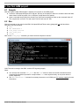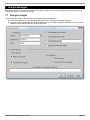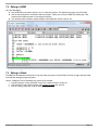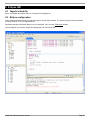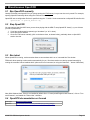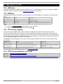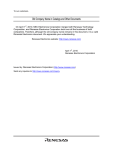
1
KNJN FX2 ARM development boards
© 2007, 2008 fpga4fun.com & KNJN LLC
http://www.knjn.com/
This document applies to the following boards.
●
●
●
Saxo-L (revisions A & B)
Xylo-L (revision A)
Xylo-LM (revision A)
Document last revision on January 13, 2008
R30
KNJN FX2 ARM development boards
Page 1
Table of Contents
1 Welcome.............................................................................................................................................................................4
1.1 This guide...................................................................................................................................................................4
1.2 ARM the easy way......................................................................................................................................................4
1.3 KNJN ARM boards.....................................................................................................................................................4
1.4 KNJN FPGA boards....................................................................................................................................................4
1.5 ARM processor...........................................................................................................................................................4
2 OpenOCD...........................................................................................................................................................................5
2.1 ARM JTAG..................................................................................................................................................................5
2.2 OpenOCD...................................................................................................................................................................5
2.3 JTAG-over-USB..........................................................................................................................................................5
3 Run OpenOCD...................................................................................................................................................................6
3.1 JTAG server................................................................................................................................................................6
3.2 Our first OpenOCD session........................................................................................................................................6
4 OpenOCD flash memory support.......................................................................................................................................7
4.1 Check the flash status................................................................................................................................................7
4.2 Erase the flash............................................................................................................................................................7
4.3 Program the flash.......................................................................................................................................................7
5 Yagarto ARM toolchain.......................................................................................................................................................8
5.1 Yagarto.......................................................................................................................................................................8
5.2 Yagarto's first file: OpenOCD + tools..........................................................................................................................8
5.3 Yagarto's second file: GNU ARM toolchain.................................................................................................................8
5.4 Yagarto's tutorials.......................................................................................................................................................8
6 Our first ARM project..........................................................................................................................................................9
6.1 Compile......................................................................................................................................................................9
6.2 Run.............................................................................................................................................................................9
7 Insight debugger...............................................................................................................................................................10
7.1 Configure Insight......................................................................................................................................................10
7.2 Debug in RAM..........................................................................................................................................................11
7.3 Debug in Flash..........................................................................................................................................................11
8 Eclipse IDE.......................................................................................................................................................................12
8.1 Yagarto's third file.....................................................................................................................................................12
8.2 Eclipse configuration................................................................................................................................................12
9 Miscellaneous OpenOCD.................................................................................................................................................13
9.1 Run OpenOCD manually..........................................................................................................................................13
9.2 Stop OpenOCD........................................................................................................................................................13
9.3 Run telnet.................................................................................................................................................................13
9.4 OpenOCD documentation on the web......................................................................................................................13
10 Miscellaneous LPC.........................................................................................................................................................14
10.1 ARM clock...............................................................................................................................................................14
10.2 ARM pins................................................................................................................................................................14
10.3 LPC memory mapping............................................................................................................................................14
10.4 LPC213x documentation on the web......................................................................................................................14
11 IOs..................................................................................................................................................................................15
11.1 LPC and FPGA connections...................................................................................................................................15
11.2 Alternate function LPC pins.....................................................................................................................................15
11.3 RS-232 with the ARM..............................................................................................................................................15
11.4 SPI with the ARM....................................................................................................................................................15
12 Board layouts..................................................................................................................................................................16
KNJN FX2 ARM development boards
Page 2
KNJN FX2 ARM development boards
Page 3
1 Welcome
1.1 This guide
Welcome to the KNJN FX2 ARM development boards guide.
This guide is partitioned in short and easy to read chapters, and shows how to work with your ARM board. In particular, it
explains step by step how to:
● Start JTAG communication with the ARM
● Compile ARM projects
● Run and debug from RAM and Flash
1.2 ARM the easy way
The KNJN ARM boards are easy to use. KNJN boards are jumper-less and work right out of the box with a simple USB
connection, so that you get up to speed quickly and concentrate on your task.
1.3 KNJN ARM boards
This document applies to the following KNJN ARM processor boards:
● Saxo-L
● Xylo-L
● Xylo/-LM
1.4 KNJN FPGA boards
Since the KNJN development boards also host an FPGA, please refer to the “KNJN FX2 FPGA boards” guide for
additional information.
The KNJN guides are available from http://www.knjn.com/docs/
1.5 ARM processor
The ARM processor used on your KNJN board is an NXP (previously Philips) LPC2132 or LPC2138, which includes an
ARM7TDMI core, SRAM, Flash, and peripherals.
The difference between the LPC2132 and LPC2138 mainly lies in the memory available.
LPC2132
LPC2138
RAM
16KB
32KB
Flash
64KB
512KB
KNJN FX2 ARM development boards
Page 4
2 OpenOCD
2.1 ARM JTAG
The ARM7TDMI core has an on-chip debug circuitry (embedded ICE) that is controlled through JTAG, and allows to take
control of the ARM core.
2.2 OpenOCD
OpenOCD, or “On-Chip Debugger“, is an open source JTAG controller software for ARM processors. It is easy to use yet
quite capable:
● Support for software and hardware ARM breakpoints.
● Interface with source-level debuggers like Eclipse.
● Flash memory programming.
OpenOCD home page can be found at http://openocd.berlios.de/web/
OpenOCD is the software used by KNJN boards to control the ARM processors. OpenOCD and its JTAG server are
provided in the KNJN boards startup kit.
2.3 JTAG-over-USB
Thanks to JTAG-over-USB, the KNJN ARM board is completely controlled through USB, without needing a separate JTAG
cable. A separate JTAG cable can nonetheless be used if required (for example, if the board USB interface is used for
other purposes). The ARM JTAG signals are available on header pins for that purpose.
KNJN FX2 ARM development boards
Page 5
3 Run OpenOCD
3.1 JTAG server
OpenOCD uses a JTAG server to be portable. The server is part of KNJN's FPGA configuration tool, so running
OpenOCD is just a few clicks away:
● Run FPGAconf
● Select your board (board menu) and ARM (“Options/ARM LPC” menu)
● Select the ARM tab
● Check the “Run OpenOCD” and “Open Telnet session” checkboxes
● Click on “Start JTAG server”
This opens OpenOCD and telnet windows similar to this:
Notes: If you are running a network firewall on your machine, respond “allow” to the network connection pop-ups. Also
with Windows Vista, Telnet is not installed by default. Go to “Control panel/Programs and Features”, click on “Turn on/off
features”, and enable the “Telnet client” checkbox.
3.2 Our first OpenOCD session
Now we can play with the ARM processor.
The KNJN board ships with a design in the LPC flash that makes the board's LED glow. Try to halt the ARM by issuing the
command “halt” in the telnet session. The LED stops blinking. Now try the “mdw 0 100” command to display the
memory content from address 0. Finally resume the processor by using the command “resume”. The LED starts glowing
again.
To see the list of everything you can do, use the “help” command.
KNJN FX2 ARM development boards
Page 6
4 OpenOCD flash memory support
To get a better idea of OpenOCD's capabilities, let's check, erase and program the ARM LPC's flash.
4.1 Check the flash status
The ARM LPC has an on-board flash memory. For example, to check the flash status (to see if it is erased or not), type:
● mww 0xE01FC040 1 (that switches the LPC memory mapping off - for details, see 10.3)
● flash erase_check 0 (that takes a few seconds) (notice the spaces and underscore in the command)
● flash info 0
That shows a list of flash sectors, with their status.
Notes:
1. The ARM needs to be stopped for these commands to work, so issue the “halt” command to stop the ARM if
required.
2. The “protected” status shown by “flash info 0” command is meaningless for the ARM LPCs.
4.2 Erase the flash
Use “flash erase 0 0 8” to erase the whole flash of an LPC2132 . The “8” is the last sector number. Change it to “26”
to erase the whole LPC2138.
4.3 Program the flash
Use “flash write 0 filename 0”.
Of course, replace “filename” with the file name that you want to program (including its path).
The startup kit includes compiled files that can be programmed in the flash. For example, try “LPC.flash.LEDglow.bin”.
Once programmed, it is executed at power up, and makes the LED glow.
For big files, flash programming can be sped up by using the command “arm7_9 dcc_downloads enable”.
KNJN FX2 ARM development boards
Page 7
5 Yagarto ARM toolchain
5.1 Yagarto
Yagarto provides a complete (and free!) development environment for the ARM. It includes an ARM GNU toolchain
(compiler & debugger) that runs natively on Windows, and works nicely with OpenOCD.
To get Yagarto, download these files from http://www.yagarto.de/.
1. OpenOCD + tools (about 2 MB)
2. Yagarto GNU ARM toolchain (about 31 MB)
3. Eclipse IDE + patches (about 72 MB)
Please note that Eclipse requires Java on your machine. If unsure, download also the Java runtime (you can get it from
http://java.sun.com/javase/downloads/index.jsp).
5.2 Yagarto's first file: OpenOCD + tools
The first file contains a version of OpenOCD, and some tools. Your board doesn't use this version of OpenOCD but it
needs the tools, so install this file. By default, this gets installed into “C:\Program Files\openocd”.
5.3 Yagarto's second file: GNU ARM toolchain
This second file contains the GNU ARM compiler and more tools, including the insight debugger. By default, this gets
installed into “C:\Program Files\yagarto”.
Now we are ready to compile our first ARM project (we'll install Yagarto's third file later).
5.4 Yagarto's tutorials
Yagarto's website has tutorials on how to install and check each step of the installation process. You may want to follow
the instructions to learn more about Yagarto (remember that when the tutorial asks to run OpenOCD, run it from the JTAG
server window).
KNJN FX2 ARM development boards
Page 8
6 Our first ARM project
6.1 Compile
Now that Yagarto's GNU ARM toolchain is installed, let's compile our first ARM project.
● Locate the “ARM project\LEDglow.LPC2138.ram” directory in the startup kit. Move it to a location where the folder
name doesn't include any space, like “c:\LEDglow” (Insight doesn't like spaces).
● Open a command line prompt (in the directory you just moved everything into) and run the command “make all”.
This compiles the “src\main.c” file and creates “test.elf” and “test.hex” files.
6.2 Run
Now let's load and run the code into the ARM. Get OpenOCD and Telnet running (paragraph 3.1) and issue these
command in the telnet window:
● halt
● mww 0xE01FC040 2
● load_image test.hex
● soft_reset_halt
● resume
Note: for the “load_image” command, you must include the full path to “test.hex”.
Voila! The code is running in the ARM... and the LED is glowing happily.
Notes:
●
●
You can issue the command “wait_halt” after the “halt” above to make sure the halt command has been
completed (that would be important in a script because halt works asynchronously, so may return before it
actually happened).
The “mww 0xE01FC040 2” command is necessary because we run in RAM (see LPC memory mapping for more
information).
KNJN FX2 ARM development boards
Page 9
7 Insight debugger
Now that we know how to load and run code into the ARM “by hand”, let's try with a debugger, which loads the code for
us, and also allows to “source-level” debug it.
7.1 Configure Insight
First we configure Insight so that it knows how to communicate with OpenOCD.
● On the command line, run the command “debug_inram.bat”. This opens the insight debugger.
● In insight, open the target selection window (using the menu “File/Target Settings”) and select TCP on port 3333.
Make sure all the other options are set as shown below.
KNJN FX2 ARM development boards
Page 10
7.2 Debug in RAM
Let's start debugging.
● Use the Run/Run command, and say “Yes” to restart the program. This loads the program in the LPC RAM.
● Use the Control/Continue command to start the program. Check your board, the ARM LED should glow. That
means that the ARM processor is executing the program.
● You can also stop the program, watch variables, put breakpoints, step line by line, etc...
The program is debugged in RAM, which is ok for small programs.
7.3 Debug in Flash
The ARM has two hardware breakpoints so can also debug a program in flash (ROM). The flash is bigger than the RAM,
so that allows debugging bigger programs.
Use the “LEDglow.LPC2138.ram&flash.zip” project as an example.
1. Compile using the “make_inflash.bat” script. This creates a “test.bin” binary file.
2. Run OpenOCD, open a telnet session and Program the flash with “test.bin”.
3. Run the “debug_inflash.bat” script to debug the program.
KNJN FX2 ARM development boards
Page 11
8 Eclipse IDE
8.1 Yagarto's third file
Run it - this installs the Eclipse IDE into “C:\Program Files\yagarto ide”
8.2 Eclipse configuration
Follow Yagarto's website tutorial to configure Eclipse to use the GNU toolchain. The tutorial is long but well documented
and easy to follow, so it is not duplicated here.
Remember that when the tutorial asks you to run OpenOCD, run it from the JTAG server window.
Once configured, you can edit, compile and debug right from the Eclipse IDE.
KNJN FX2 ARM development boards
Page 12
9 Miscellaneous OpenOCD
9.1 Run OpenOCD manually
Usually FPGAconf runs OpenOCD for you (when starting the JTAG server), but you can also run it yourself. For example,
opening OpenOCD manually allows using the JTAG server remotely.
OpenOCD uses a configuration file that is specified using the “-f” switch. So the command to run OpenOCD looks like this:
openocd.exe -f openocd_LPC2132.cfg
9.2 Stop OpenOCD
You may want to stop OpenOCD once you are done playing with the ARM. To stop OpenOCD “cleanly”, try one of these
(in order of preference):
1. If you have a telnet session opened, type “shutdown” (or “sh” in short).
2. Close OpenOCD's window.
3. Close the JTAG server manually (click on the button close, as shown below), preferably when no OpenOCD
session is active.
9.3 Run telnet
When OpenOCD is running, a telnet session allows to communicate with it on a “command-line” like window.
FPGAconf allows opening a telnet session automatically for you. But telnet session can also be opened manually by
running the command “telnet localhost 4444” (either as a line of command, or using the “Start/Run...” button of Windows).
Note: With Windows Vista, Telnet is not installed by default. Go to “Control panel/Programs and Features”, click on “Turn
on/off features”, and enable the “Telnet client” checkbox.
9.4 OpenOCD documentation on the web
Home page
http://openocd.berlios.de/web/
OpenFacts
http://openfacts.berlios.de/index-en.phtml?title=Open_On-Chip_Debugger
KNJN FX2 ARM development boards
Page 13
10 Miscellaneous LPC
10.1 ARM clock
All KNJN ARM boards use a 24MHz to clock (externally) the LPC. The LPC ARM core clock can be raised up to 60MHz
internally by using an internal PLL (see the LPC213x user manual for more details).
10.2 ARM pins
Most ARM IOs are exported on headers around the ARM but a few special ARM pins are available on individual header
pads.
ARM special pins
Saxo-L
Xylo-L/-LM
RTXC (real-time clock)
Available at the bottom of the board
Available on header pins
VBAT
Not available
Available on a small pad
VREF
Wired to 3.3V
Available on a small pad (1Kohms pullup resistor to +3.3V)
Notes:
●
●
Check the KNJN FPGA boards documentation for the pin locations.
Some ARM IOs are also connected to IOs, see chapter 11.
10.3 LPC memory mapping
The first 64 bytes of the ARM memory space at location 0 are special (they hold the reset and interrupt vectors).
The LPC normally puts flash memory at location 0, but during RAM debug sessions, we don't want to worry about the
flash (it would be a pain to have to re-program the flash every time you want to debug in RAM). So the LPC implements a
feature to allow mapping this space to RAM. The space is also mapped to a “boot loaded” after reset (a special feature of
the LPC that allows to program the flash from a serial port).
The MEMMAP “Memory Mapping control register” resides at address 0xE01FC040 in the LPC memory space and can
take 3 values:
MEMMAP values
Usage
When to use
0 (Boot Loader Mode)
Interrupt vectors are re-mapped to Boot Block
The device boots
1 (User Flash Mode)
Interrupt vectors are not re-mapped and reside in Flash
We want to run code from Flash, or check if the
flash is erased
2 (User RAM Mode)
Interrupt vectors are re-mapped to Static RAM
We want to run code from RAM
For more details, check the MEMMAP register in the LPC213x user manual.
10.4 LPC213x documentation on the web
Home page
http://www.nxp.com/pip/LPC2132FBD64.html
Data sheet
http://www.nxp.com/acrobat/datasheets/LPC2131_32_34_36_38_4.pdf
User Manual
http://www.standardics.nxp.com/support/documents/microcontrollers/pdf/user.manual.lpc2131.lpc2132.lpc2134.lpc2136.lpc2138.pdf
KNJN FX2 ARM development boards
Page 14
11 IOs
11.1 LPC and FPGA connections
KNJN development boards also host an FPGA, and many LPC pins are connected to the FPGA, so that they can
communicate together.
LPC pin
SAXO-L
XYLO-L/-LM
P0.0 (TXD0)
P0.1 (RXD0)
P0.2 (SCL0)
FPGA pin 22
P0.3 (SDA0)
FPGA pin 20
P0.4 (SCK0)
FPGA pin 19
P0.5 (MISO0)
FPGA pin 18
P0.6 (MOSI0)
FPGA pin 16
P0.7 (SSEL0)
FPGA pin 15
P0.8 (TXD1)
FPGA pin 14
P0.9 (RXD1)
FPGA pin 12
P0.10 (RTS1)
FPGA pin 11
P0.11 (CTS1)
FPGA pin 9
P0.12 (DSR1)
FPGA pin 8
P0.13 (DTR1)
FPGA pin 6
P0.14 (DCD1)
FPGA pin 5
P0.15 (RI1)
FPGA pin 4
P0.16 (EINT0)
FPGA pin 3
P0.17 (SCK1)
FPGA pin 51
FPGA pin 2
P0.18 (MISO1)
FPGA pin 52
FPGA pin 199
P0.19 (MOSI1)
FPGA pin 56
FPGA pin 200
P0.20 (SSEL1)
FPGA pin 57
P0.21 (PWM5)
P0.22 (CAP0.0)
FPGA pin 53
P0.23
P0.25 (AD0.4)
FPGA pin 204
FPGA pin 55
P0.26 (AD0.5)
P0.27 (AD0.0)
P0.28 (AD0.1)
P0.29 (AD0.2)
P0.30 (AD0.3)
P0.31
LED2
LED1
LED1
More connections can be added if required by soldering wires to the board.
11.2 Alternate function LPC pins
Most LPC pins can have different personalities. For example:
● The pins RXD and TXD (P0.0/1 or P0.8/9) allow the implementation of a serial asynchronous interface (like
RS-232).
● The pins SCK, MOSI and MISO (P0.4/5/6 or P0.17/18/19) allow the implementation of a serial synchronous
interface (like SPI).
11.3 RS-232 with the ARM
The ARM processor can drive a MAX232 board like a TXDI/MAX232 through its pins RxD and TxD. There is no connector
dedicated for these pins, so the MAX232 board needs to be wired manually to the right headers pins (see 11.2).
11.4 SPI with the ARM
The ARM processor and FPGA can communicate through an SPI interface.
More information at:
● Paragraph 11.2 and the startup kit's “ARM project – SPI”
● fpga4fun's SPI project
KNJN FX2 ARM development boards
Page 15
12 Board layouts
Check the KNJN FPGA boards documentation (paragraph 1.4).
KNJN FX2 ARM development boards
Page 16