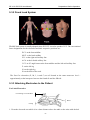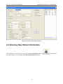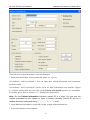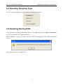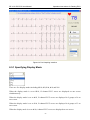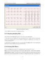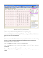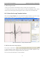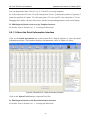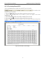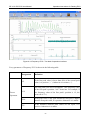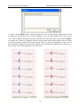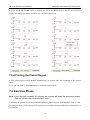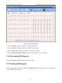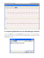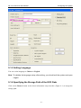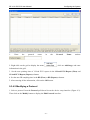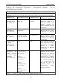
1
About this Manual
P/N: 01.54.106666-17
Release Date: July 2010
© Copyright EDAN INSTRUMENTS, INC. 2008-2010. All rights reserved.
Statement
This manual will help you understand the operation and maintenance of the product better. It is
reminded that the product shall be used strictly complying with this manual. User’s operation
failing to comply with this manual may result in malfunction or accident for which EDAN
INSTRUMENTS, INC. (hereinafter called EDAN) can not be held liable.
EDAN owns the copyrights of this manual. Without prior written consent of EDAN, any
materials contained in this manual shall not be photocopied, reproduced or translated into other
languages.
Materials protected by the copyright law, including but not limited to confidential information
such as technical information and patent information are contained in this manual, the user shall
not disclose such information to any irrelevant third party.
The user shall understand that nothing in this manual grants him, expressly or implicitly, any
right or license to use any of the intellectual properties of EDAN.
EDAN holds the rights to modify, update, and ultimately explain this manual.
Responsibility of the Manufacturer
EDAN only considers itself responsible for any effect on safety, reliability and performance of
the equipment if:
Assembly operations, extensions, re-adjustments, modifications or repairs are carried out by
persons authorized by EDAN, and
The electrical installation of the relevant room complies with national standards, and
The instrument is used in accordance with the instructions for use.
Upon request, EDAN may provide, with compensation, necessary circuit diagrams, and other
information to help qualified technician to maintain and repair some parts, which EDAN may
define as user serviceable.
I
Terms Used in this Manual
This guide is designed to give key concepts on safety precautions.
WARNING
A WARNING label advises against certain actions or situations that could result in personal
injury or death.
CAUTION
A CAUTION label advises against actions or situations that could damage equipment, produce
inaccurate data, or invalidate a procedure.
NOTE: A NOTE provides useful information regarding a function or a procedure.
II
Table of Contents
Chapter 1 Safety Guidance ........................................................................................................... 1
1.1 Intended Use........................................................................................................................ 1
1.2 Warnings and Cautions........................................................................................................ 1
1.2.1 General Warnings ...................................................................................................... 1
1.2.2 General Cautions....................................................................................................... 3
1.2.3 Preparation and Operation Warnings (for Exercise ECG) ........................................ 5
1.2.4 Contraindications (for Exercise ECG) ...................................................................... 6
1.3 List of Symbols ................................................................................................................... 7
Chapter 2 Introduction.................................................................................................................. 8
2.1 SE-1010 PC ECG System ................................................................................................... 8
2.2 ECG Sampling Box Appearance....................................................................................... 10
2.3 Features ............................................................................................................................. 13
Chapter 3 Assembling SE-1010 PC ECG System...................................................................... 15
Chapter 4 Installing SE-1010 PC ECG Software ...................................................................... 17
4.1 System Running Environment .......................................................................................... 17
4.1.1 Requirements on the Hardware of the PC............................................................... 17
4.1.2 Requirements on the Software of the PC ................................................................ 17
4.2 About Installation Interface............................................................................................... 18
Chapter 5 Preparations Before Operation................................................................................. 19
5.1 Preparing the Patient ......................................................................................................... 19
5.1.1 Instructing the Patient ............................................................................................. 19
5.1.2 Preparing the Skin ................................................................................................... 19
5.2 Connecting the Patient Cable to the Electrodes ................................................................ 19
5.3 Attaching Electrodes (for Resting ECG)........................................................................... 20
5.3.1 Wilson Lead System................................................................................................ 21
5.3.2 Frank Lead System.................................................................................................. 22
5.3.3 Attaching Electrodes to the Patient ......................................................................... 22
5.4 Attaching Electrodes to the Patient (for Exercise ECG) ................................................... 24
5.5 Inspection Before Test....................................................................................................... 26
Chapter 6 Operation Instructions for Resting ECG................................................................. 28
6.1 Viewing Lead Placement Information............................................................................... 29
6.2 Selecting a Patient Record to Start a New Test ................................................................. 29
6.3 Entering New Patient Information .................................................................................... 32
6.4 Selecting Sampling Type................................................................................................... 34
6.5 Sampling Resting ECG ..................................................................................................... 34
6.5.1 Specifying Display Mode........................................................................................ 35
6.5.2 Specifying Lowpass Filter....................................................................................... 36
6.5.3 Specifying Gain....................................................................................................... 36
III
6.5.4 Specifying Speed..................................................................................................... 36
6.5.5 Recording ECG Data............................................................................................... 36
6.5.6 Freezing and Previewing ECG................................................................................ 37
6.5.7 Stopping Sampling Data ......................................................................................... 38
6.5.8 Printing ECG Waves ............................................................................................... 38
6.6 Analyzing ECG Data.........................................................................................................39
6.6.1 Analyzing Normal ECG .......................................................................................... 39
6.6.1.1 Viewing the Waveform.................................................................................. 39
6.6.1.2 About the Average Template Interface .......................................................... 42
6.6.1.3 About the Detail Information Interface ......................................................... 43
6.6.1.4 Previewing Normal ECG .............................................................................. 44
6.6.2 Analyzing QT Dispersion........................................................................................ 45
6.6.2.1 Editing Waveform on the QT Dispersion Interface....................................... 46
6.6.2.2 About QT Value............................................................................................. 47
6.6.2.3 Previewing QT Dispersion............................................................................ 47
6.6.3 Analyzing Frequency ECG ..................................................................................... 48
6.6.3.1 About Two-lead Comparison Interface ......................................................... 48
6.6.3.2 About 12-lead Power Spectrum Interface ..................................................... 51
6.6.3.3 Previewing Frequency ECG.......................................................................... 51
6.6.4 Analyzing High Frequency ECG ............................................................................ 53
6.6.5 Analyzing HRV ....................................................................................................... 55
6.6.5.1 Editing the HRV Data on the Analysis Interface........................................... 56
6.6.5.2 Editing the HRV Waveform on the Waveform Interface .............................. 57
6.6.5.3 Previewing HRV ........................................................................................... 58
6.6.5.4 Printing HRV Wave....................................................................................... 58
6.6.6 Analyzing HRT........................................................................................................ 59
6.6.7 Analyzing Vector ECG ............................................................................................ 61
6.6.7.1 Displaying Vector ECG with All Plane and All Loop................................... 62
6.6.7.2 Displaying Vector ECG with Frontal Plane and QRS Loop ......................... 64
6.6.7.3 Displaying 3D Vector ECG........................................................................... 65
6.6.7.4 Previewing Vector ECG ................................................................................ 66
6.6.8 Analyzing Time Vector ECG................................................................................... 66
6.6.9 Analyzing Signal Averaged ECG ............................................................................ 68
6.6.9.1 About the Time Domain Interface................................................................. 69
6.6.9.2 About the Frequency Domain Interface ........................................................ 69
6.6.9.3 Previewing Signal Averaged ECG ................................................................ 70
6.6.10 Printing ECG Reports ........................................................................................... 71
6.6.11 Saving ECG Reports ............................................................................................. 72
6.7 Sampling STAT ECG ........................................................................................................ 73
Chapter 7 Operation Instructions for Exercise ECG ............................................................... 74
IV
7.1 Viewing Lead Placement Information............................................................................... 74
7.2 Selecting a Patient Record to Start a New Test ................................................................. 75
7.2.1 Setting Target HR.................................................................................................... 76
7.2.2 Setting Normal BP .................................................................................................. 76
7.2.3 Setting a Protocol .................................................................................................... 77
7.2.4 Setting Post J ........................................................................................................... 77
7.2.5 Setting BP Sampling Mode ..................................................................................... 77
7.2.6 Setting BP Triggering Mode ................................................................................... 77
7.2.7 Setting Auto Printing............................................................................................... 78
7.3 Entering New Patient Information .................................................................................... 78
7.4 Pre-sampling ECG ............................................................................................................ 80
7.5 Pretest Phase...................................................................................................................... 81
7.5.1 Viewing the Heart Rate and the Blood Pressure ..................................................... 82
7.5.2 Viewing Other Information ..................................................................................... 83
7.5.3 Editing the Waveform ............................................................................................. 83
7.5.4 Printing the Pretest Report ...................................................................................... 85
7.6 Exercise Phase................................................................................................................... 85
7.7 Recovery Phase ................................................................................................................. 86
7.8 Exiting the Exercise Test................................................................................................... 87
7.9 About Analysis Interface ................................................................................................... 88
7.9.1 About Summary Interface ....................................................................................... 88
7.9.2 About ST Analysis Interface ................................................................................... 91
7.9.3 About All View Review Interface ........................................................................... 93
7.9.4 About Trend Interface ............................................................................................. 96
7.9.5 About ECG Strip Interface ...................................................................................... 96
7.9.6 Previewing ECG Reports ........................................................................................ 97
7.9.7 Printing ECG Reports ............................................................................................. 97
7.9.8 Saving ECG Reports ............................................................................................... 98
7.9.9 Exiting the Analysis Interface ................................................................................. 98
Chapter 8 Processing Patient Records ....................................................................................... 99
8.1 Searching Patient Records................................................................................................. 99
8.2 Modifying Patient Records ............................................................................................. 101
8.3 Deleting Records............................................................................................................. 102
8.3.1 Deleting Patient Records....................................................................................... 102
8.3.2 Deleting Examination Records of a Patient .......................................................... 102
8.4 Selecting a Patient Record .............................................................................................. 102
8.5 Merging Examination Records ....................................................................................... 103
8.6 Comparing Two Examination Records ........................................................................... 103
8.7 Importing ECG Data into the Data Manager Interface ................................................... 104
8.8 Exporting ECG Data from the Data Manager Interface.................................................. 105
V
8.9 Viewing an Examination Record..................................................................................... 106
Chapter 9 Configuring the System ........................................................................................... 107
9.1 Basic Information Setup.................................................................................................. 107
9.1.1 Setting Basic Information ..................................................................................... 108
9.1.2 Setting ID Mode.................................................................................................... 109
9.1.3 Setting Name Mode............................................................................................... 110
9.1.4 Selecting D.O.B .................................................................................................... 110
9.1.5 Setting Language................................................................................................... 111
9.1.6 Specifying the Storage Path of the ECG Data ...................................................... 111
9.2 Sample Setup................................................................................................................... 112
9.2.1 Setting Filter.......................................................................................................... 112
9.2.2 Setting Sampling Time.......................................................................................... 113
9.2.3 Setting Lead Sequence .......................................................................................... 113
9.2.4 Setting Pacemaker Detection ................................................................................ 113
9.2.5 Setting HR Calculation Lead ................................................................................ 114
9.2.6 Selecting Auto Printing When Detecting Arrhythmia........................................... 114
9.2.7 Setting Auto Upload When Stopping Sampling.................................................... 114
9.2.8 Setting Background Grid ...................................................................................... 114
9.2.9 Setting Anti-aliasing.............................................................................................. 114
9.2.10 Selecting QRS Voice ........................................................................................... 114
9.3 Device Setup ................................................................................................................... 115
9.3.1 Setting Sampling Device....................................................................................... 115
9.3.2 Setting Device Type/Mode.................................................................................... 116
9.3.3 Setting COM Port of Sample/Treadmill/BP Monitor............................................ 116
9.3.4 Setting a Protocol .................................................................................................. 116
9.3.4.1 Creating a New Protocol ............................................................................. 116
9.3.4.2 Modifying a Protocol .................................................................................. 117
9.3.4.3 Deleting a Protocol...................................................................................... 118
9.3.4.4 Restoring the Factory Settings .................................................................... 119
9.4 Printer Setup.................................................................................................................... 119
9.4.1 Choosing Patient Information to be Printed.......................................................... 119
9.4.2 Choosing Diagnosis Information to be Printed..................................................... 120
9.4.3 Setting Rhythm Lead............................................................................................. 120
9.4.4 Defining Printing Format ...................................................................................... 120
9.5 Other Setup...................................................................................................................... 121
9.6 GDT Setup ...................................................................................................................... 122
9.7 Modifying the Glossary................................................................................................... 123
Chapter 10 Hint Information.................................................................................................... 124
Chapter 11 Cleaning and Maintenance.................................................................................... 126
11.1 Cleaning and Maintaining the Treadmill....................................................................... 126
VI
11.2 Cleaning and Maintaining the Patient Cable and Reusable Electrodes ........................ 126
11.3 Disinfection ................................................................................................................... 127
Chapter 12 Accessories .............................................................................................................. 128
Chapter 13 Warranty and Service Policy ................................................................................ 129
13.1 Warranty ........................................................................................................................ 129
13.2 Service Policy................................................................................................................ 129
Chapter 14 Recommended Optional Accessories.................................................................... 131
Appendix 1 Technical Specifications ........................................................................................ 133
A1.1 Safety Specifications .................................................................................................... 133
A1.2 Environment Specifications ......................................................................................... 133
A1.3 Physical Specifications................................................................................................. 134
A1.4 Power Supply Specifications........................................................................................ 134
A1.5 Performance Specifications.......................................................................................... 134
Appendix 2 EMC Information.................................................................................................. 136
Appendix 3 Abbreviation........................................................................................................... 140
VII
SE-1010 PC ECG User Manual
Safety Guidance
Chapter 1 Safety Guidance
This chapter provides important safety information related to the use of SE-1010 PC ECG.
1.1 Intended Use
SE-1010 PC ECG is a PC-based diagnostic tool intended to acquire, process and store ECG
signals from adult and pediatric patients undergoing stress exercise test or resting test. SE-1010
PC ECG is intended to be used only in hospitals and healthcare facilities by doctors and trained
healthcare professionals. The cardiogram recorded by SE-1010 PC ECG can help users to analyze
and diagnose heart disease. However the ECG with measurements and interpretive statements is
offered to clinicians on an advisory basis only.
1.2 Warnings and Cautions
To use the system safely and effectively, firstly be familiar with the operation method of
Windows and read the user manual in detail to be familiar with the proper operation method
for the purpose of avoiding the possibility of system failure. The following warnings and
cautions must be paid more attention to during the operation of the system.
Notes:
1. This system is not intended for home use.
2. The pictures and interfaces in this manual are for reference only.
1.2.1 General Warnings
WARNING
1.
The system is intended to be used by qualified physicians or personnel
professionally trained. They should be familiar with the contents of this user manual
before operation.
2.
Only qualified service engineers can install this equipment, and only service
engineers authorized by the manufacturer can open the shell.
3.
The results given by the system should be examined based on the overall clinical
condition of the patient, and it can not substitute for regular checking.
4.
This system is not intended for treatment.
5.
This system is not designed for direct cardiac application.
-1-
SE-1010 PC ECG User Manual
Safety Guidance
WARNING
6.
EXPLOSION HAZARD - Do not use the system in the presence of flammable
anesthetic mixtures with oxygen or other flammable agents.
7.
SHOCK HAZARD - The power receptacle must be a hospital grade grounded outlet.
Never try to adapt the three-prong plug to fit a two-slot outlet.
8.
Do not use this system in the presence of high static electricity or high voltage
equipment which may generate sparks.
9.
In order to avoid being burnt, please keep the electrodes far away from the radio
knife while using electrosurgical equipment.
10. Only the patient cable supplied by the manufacturer can be used. Or else, the
performance and electric shock protection can not be guaranteed.
11. Turn off the system power and remove the power cable before servicing or
maintaining the system.
12. Please do not operate the system during servicing or before it is running normally.
13. Make sure that all electrodes are connected to the patient correctly before operation.
14. Ensure that the conductive parts of electrodes and associated connectors, including
neutral electrodes, do not come in contact with earth or any other conducting
objects.
15. Electrodes with defibrillator protection should be used while defibrillating.
16. The disposable electrodes can only be used for one time.
17. Electrodes of dissimilar metals should not be used; otherwise it may cause a high
polarization voltage.
18. Do not touch the patient, bed, table or the system simultaneously while using the
system together with a defibrillator.
19. If reusable electrodes with electrode gel are used during defibrillation, the ECG
recovery will take more than 10 seconds. The manufacturer recommends the use of
disposable electrodes at all times.
20. Accessory equipment connected to the analog and digital interfaces must be
certified according to the respective IEC/EN standards (e.g. IEC/EN 60950 for data
processing equipment and IEC/EN 60601-1 for medical equipment). Furthermore all
configuration shall comply with the valid version of the standard IEC/EN 60601-1-1.
Therefore anybody, who connects additional equipment to the signal input or output
connector to configure a medical system, must make sure that it complies with the
requirements of the valid version of the system standard IEC/EN 60601-1-1. If in
doubt, consult our technical service department or your local distributor.
-2-
SE-1010 PC ECG User Manual
Safety Guidance
WARNING
21. The summation of leakage current should never exceed leakage current limits while
several other units are used at the same time.
22. The equipment is protected against malfunctions caused by electrosurgery
according to the clause 36.202.101 in the standard IEC60601-2-25.
23. To the patient with a pacemaker, the results given by the system may be invalid.
1.2.2 General Cautions
CAUTION
1.
Federal (US) law restricts this device to sale by or on the order of a physician.
2.
Avoid liquid splash and excessive temperature. The temperature must be kept
between 5 ºC and 40 ºC during operation.
3.
Do not use the system in a dusty environment with bad ventilation or in the presence
of corrosive.
4.
Make sure that there is no intense electromagnetic interference source around the
system, such as radio transmitters, mobile phones etc. Attention: large medical
electrical equipment such as electrosurgical equipment, radiological equipment and
magnetic resonance imaging equipment is likely to bring electromagnetic
interference.
5.
Before use, the system, the patient cable, electrodes etc, should be checked.
Replacement should be taken if there is any evident defectiveness or aging
symptom which may impair the safety or the performance.
6.
The following safety checks should be performed at least every 24 months by a
qualified person who has adequate training, knowledge, and practical experience to
perform these tests.
a) Inspect the equipment and accessories for mechanical and functional damage.
b) Inspect the safety related labels for legibility.
c) Inspect the fuse to verify compliance with the rated current and circuit-breaking
characteristics.
d) Verify that the device functions properly as described in the instructions for use.
e) Test the protection earth resistance according to IEC/EN 60601-1: Limit: 0.1 ohm.
f) Test the earth leakage current according to IEC/EN 60601-1: Limit: NC 500 μA,
SFC 1000 μA.
-3-
SE-1010 PC ECG User Manual
Safety Guidance
CAUTION
g) Test the enclosure leakage current according to IEC/EN 60601-1: Limit: NC 100
μA, SFC 500 μA.
h) Test the patient leakage current according to IEC/EN 60601-1: Limit: NC a.c. 10
μA, d.c. 10 μA; SFC a.c. 50 μA, d.c. 50 μA.
i) Test the patient auxiliary current according to IEC/EN 60601-1: Limit: NC a.c. 10
μA, d.c. 10 μA; SFC a.c. 50 μA, d.c. 50 μA.
j) Test the patient leakage current under single fault condition with mains voltage on
the applied part according to IEC/EN 60601-1: Limit: 50 μA (CF).
The data should be recorded in an equipment log. If the equipment is not functioning
properly or fails any of the above tests, the equipment has to be repaired.
7.
The device and accessories are to be disposed of according to local regulations after
their useful lives. Alternatively, they can be returned to the dealer or the
manufacturer for recycling or proper disposal.
8.
Precautionary maintenance of this system, including periodically cleaning and
checking the appearance, can be finished by users because this maintenance does
not touch the interior.
9.
Before cleaning or maintaining the system, turn off the system power and remove
the power cable.
10. Prevent the detergent from seeping into the equipment while cleaning.
11. Avoid pouring liquid on the equipment while cleaning, and do not immerse any parts
of the equipment into any liquid.
12. Do not clean the unit and accessories with abrasive fabric and avoid scratching the
electrodes. Removing all dust from the exterior surface of the equipment with a soft
brush or cloth, or with a soft cloth which is slightly dampened with a mild detergent
solution or cool disinfector. Especially the tie-in and the panel edge should be
noticed.
13. Any remainder of detergent should be removed from the unit and the patient cable
after cleaning.
14. Do not use chloric disinfectant such as chloride, sodium hypochlorite etc.
-4-
SE-1010 PC ECG User Manual
Safety Guidance
1.2.3 Preparation and Operation Warnings (for Exercise ECG)
WARNING
1.
Ensure that the main unit and the treadmill are effectively grounded.
2.
Test the emergency stop switch of the treadmill before using the system.
3.
During the exercise testing, ensure that there are at least 2 experienced physicians
present. One of them observes the patient and deals with the emergency.
4.
Make sure that there is necessary valid first-aid equipment such as the defibrillator,
the blood-pressure meter etc, and necessary valid medication in the exercise testing
room.
5.
Turn off the system power and disconnect the power cord from the wall outlet after
using the system.
6.
Press down the emergency stop switch of the treadmill before defibrillating to avoid
the hazard to the patient and the operator.
7.
Keep the four feet of the treadmill on a horizontal place and make sure it’s stably
working.
8.
Make sure that the power cable of the treadmill is grounded. Don’t use other
electrical equipment with the same power supply line.
9.
Keep the power cable far away from the running treadmill area and the heat surface.
10. Examine the treadmill carefully before using it.
11. Do not do an exercise test if the treadmill is wet.
12. Do not use the treadmill in the open air.
13. The patient undergoing stress exercise testing should wear suitable clothes and
shoes.
14. During the stress exercise testing, the patient should not get on or off the treadmill.
15. Remind patients to take care not to fall down from the treadmill.
16. Keep hands, hair, jewelry and loose clothing away from moving parts of the treadmill.
17. After the exercise phase, slow the speed of the treadmill to the minimum, and then
stop the treadmill.
18. Children are prohibited from approaching the treadmill alone.
19. Don’t insert anything into the treadmill, or place anything on its surface.
20. Press down the emergency stop switch to stop the treadmill immediately the
emergency happens.
-5-
SE-1010 PC ECG User Manual
Safety Guidance
1.2.4 Contraindications (for Exercise ECG)
Absolute Contraindications:
1. Acute MI (within 2 days)
2. High-risk unstable angina
3. Hemodynamic compromise caused by uncontrolled cardiac arrhythmia
4. Active endocarditis
5. Symptomatic severe aortic stenosis
6. Decompensated symptomatic heart failure
7. Acute pulmonary embolus or pulmonary infarction
8. Acute noncardiac disorder that may affect exercise performance or be
aggravated by exercise (eg, infection, renal failure, thyrotoxicosis)
9. Acute myocarditis or pericarditis
10. Physical disability that would preclude safe and adequate test performance
11. The patient opposes the test.
Relative Contraindications:
1. Left main coronary stenosis or its equivalent
2. Moderate stenotic valvular heart disease
3. Electrolyte abnormalities
4. Tachyarrhythmias or bradyarrhythmias
5. Atrial fibrillation with uncontrolled ventricular rate
6. Hypertrophic cardiomyopathy
7. Patients can not cooperate because of mental impairment
8. High-degree AV block
-6-
SE-1010 PC ECG User Manual
Safety Guidance
1.3 List of Symbols
Equipment or part of CF type with defibrillator proof
Caution
Consult Instructions for Use
Recycle
Part Number
Serial Number
Date of Manufacture
Manufacturer
Authorized Representative in the European Community
The symbol indicates that the device complies with the
European Council Directive 93/42/EEC concerning medical
devices.
It indicates that the device should be sent to the special agencies
according to local regulations for separate collection after its
useful life.
Rx only (U.S.)
Federal (US) law restricts this device to sale by or on the order
of a physician
-7-
SE-1010 PC ECG User Manual
Introduction
Chapter 2 Introduction
SE-1010 PC ECG has similar functions with an ordinary electrocardiograph. ECG data can be
sampled, analyzed and stored in a PC, and it can be saved in PDF, Word, BMP or JPG format.
ECG waves can be frozen and reviewed. Auto measurement and diagnosis are available, and
the diagnosis template can be edited.
When a patient with coronary heart disease runs, the added heart load will cause myocardium
hypotension, and then the ECG will change abnormally. Therefore, with the function of
exercise ECG, SE-1010 PC ECG can also be used to diagnose concealed coronary heart disease
and atypical angina pectoris, prescribe the workload for patients with myocardial infarction
before they leave hospital, and assess the effect of the treatment.
Note: The exercise ECG function is optional. It is available only if you purchased this
function.
With SE-1010 PC ECG, doctors’ workload can be reduced greatly.
WARNING
1. This system is intended for use on adult and pediatric patients only.
2. Ensure that there is no other database software in the PC in which our software will be
installed.
Note: This system is not designed for direct cardiac application.
2.1 SE-1010 PC ECG System
SE-1010 PC ECG system includes the following equipment:
PC in which PC ECG software is installed (Manually Configured)
ECG Sampling Box
Printer (Manually Configured)
Treadmill or Ergometer (Manually Configured)
Patient Cable
Electrodes
Softdog
Note: If the PC is not purchased from our company, we will not be held responsible for
the maintenance of the PC hardware or the operating system.
-8-
SE-1010 PC ECG User Manual
Introduction
SE-1010 PC ECG System
Treadmill or Ergometer
(Manually Configured)
Serial
Cable (for
exercise
ECG only)
Patient
Patient Cable
ECG
PC (Manually
Configured)
Cable
ECG Sampling Box
ECG
BP Monitor
(Manually
Configured)
Cable
USB Cable
(for exercise
ECG only)
Printer (Manually
Configured)
WARNING
The system should be installed by a qualified service engineer. Do not power on the
system until all cables are properly connected and verified.
-9-
SE-1010 PC ECG User Manual
Introduction
2.2 ECG Sampling Box Appearance
ECG Sampling Box Appearance
Front Panel
Lamp
USB Socket
Name
Explanation
Lamp
When the ECG sampling box is powered by the PC, the lamp
will be lit.
USB Socket
Connecting to the USB socket of the PC with a USB cable
- 10 -
SE-1010 PC ECG User Manual
Introduction
USB Socket
Definitions of corresponding pins:
Pin
Signal
Pin
Signal
1
GND
6
GND
2
VCC
7
GND
3
QRS
8
GND
4
GND
9
D-
5
GND
10
D+
WARNING
1. When the computer connected to the USB cable is powered on, do not connect the
USB cable to the ECG sampling box; when the system is powered on, do not disconnect
the USB cable from the ECG sampling box.
2. It is not necessary or recommended to regularly disconnect the USB cable from the
ECG sampling box. Disconnect the USB cable from the PC if necessary.
Back Panel
Patient Cable Socket
: Applied part of type CF with defibrillator proof
- 11 -
SE-1010 PC ECG User Manual
Introduction
: Caution
Patient Cable Socket
Definitions of corresponding pins:
Pin
Signal
Pin
Signal
Pin
Signal
1
C2 / V2
6
SH
11
F / LL
2
C3 / V3
7
NC
12
C1 / V1
or NC
3
C4 / V4
8
NC
13
C1 / V1
4
C5 / V5
9
R / RA
14
RF (N) /RL
or NC
5
C6 / V6
10
L / LA
15
RF (N) / RL
Note: The left side of “/” is European standard, and the right side is American standard.
Top Panel and Bottom Panel
Screw
Label
Decorative
Chip
- 12 -
SE-1010 PC ECG User Manual
Introduction
WARNING
1. Accessory equipment connected to the analog and digital interfaces must be certified
according to the respective IEC/EN standards (e.g. IEC/EN 60950 for data
processing equipment and IEC/EN 60601-1 for medical equipment). Furthermore all
configuration shall comply with the valid version of the standard IEC/EN 60601-1-1.
Therefore anybody, who connects additional equipment to the signal input or output
connector to configure a medical system, must make sure that it complies with the
requirements of the valid version of the system standard IEC/EN 60601-1-1. If in
doubt, consult our technical service department or your local distributor.
2. The summation of leakage current should never exceed the leakage current limit
while several other units are used at the same time.
2.3 Features
Powerful functions, friendly interfaces and easy operation
3/6/12-channel ECG waves are displayed and printed simultaneously
ECG waves can be frozen and reviewed
Supporting auto measurement and diagnosis
Measurement point adjustment and re-analysis, manual measurement with an electronic
ruler of high precision
Perfect data management and processing functions
Reports can be printed in PDF, Word, JPG or BMP format
Supporting multi-language
Updated to be a network electrocardiograph, transmitting ECG data over LAN or WAN
or INTERNET
Automatic baseline adjustment for optimal printing
High performance filters guarantee stable ECG waveforms
Real-time analysis, real-time displaying and printing 12-lead simultaneous ECG
waveforms
Nine analysis functions including Normal ECG, Frequency ECG, High Frequency ECG,
- 13 -
SE-1010 PC ECG User Manual
Introduction
QT Dispersion, Vector ECG, Time Vector ECG, HRT analysis, HRV analysis and Signal
Averaged ECG (Only for resting ECG)
The following features are only for the exercise test function of SE-1010 PC ECG
Automatically controlling and adjusting the speed and the elevation of the treadmill
Supporting many kinds of treadmills and ergometers
Providing classical exercise protocols; new exercise protocols can be added to the
system
ST segment analysis and measurement of 12-lead waveforms while sampling ECG; ST
position is adjustable while sampling ECG
Providing summaries, ST analysis, wave reviews and trends
Providing specific statistic data of each lead in each stage
Providing average waves of each lead in each stage for you to observe the changes of
ST segments among different stages
- 14 -
SE-1010 PC ECG User Manual
Assembling SE-1010 PC ECG System
Chapter 3 Assembling SE-1010 PC ECG
System
1
2
Patient Cable for Resting ECG
Patient Cable for Exercise ECG
5
6
3
4
7
ECG Sampling Box
8
Cable for Exercise ECG
9
Cable for Resting ECG
For resting ECG,
1. Insert plug 1 of the patient cable into socket 3 of the ECG sampling box.
- 15 -
SE-1010 PC ECG User Manual
Assembling SE-1010 PC ECG System
2. Insert plug 8 of the cable into socket 4 of the ECG sampling box.
3. Insert plug 9 of the cable into the USB socket of the PC.
4. Connect a printer to the PC.
5. Insert the LPT softdog into the parallel interface of the PC, or insert the USB softdog into
the USB socket of the PC.
6. Make sure that the above parts are properly connected, and then connect the PC, and the
printer to the power supply.
For exercise ECG,
1. Insert plug 2 of the patient cable into socket 3 of the ECG sampling box.
2. Insert plug 5 of the cable into socket 4 of the ECG sampling box.
3. Insert plug 6 of the cable into the USB socket of the PC.
4. Connect plug 7 of the cable to the BP monitor.
WARNING
Only stress BP monitors can be used.
5. Connect a treadmill or an ergometer to the PC.
6. Connect a printer to the PC.
7. Insert the LPT softdog into the parallel interface of the PC, or insert the USB softdog into
the USB socket of the PC.
8. Make sure that the above parts are properly connected, and then connect the PC,
treadmill/ergometer and printer to the power supply.
WARNING
1. Use a special grounded socket to get accurate voltage and current.
2. When using a notebook computer with a two-prong plug, please connect a grounded
printer to avoid power interference.
- 16 -
SE-1010 PC ECG User Manual
Chapter 4
Software
Installing SE-1010 PC ECG Software
Installing
SE-1010
PC
ECG
4.1 System Running Environment
4.1.1 Requirements on the Hardware of the PC
CPU:
Pentium P4, Celeron D 310 or above
System Memory (RAM):
512MB or above
Main Board
Recommend the main board of Intel chipset
Hard Disk:
40G or above
ink jet printer of more than 600dpi or laser printer
Printer:
Recommend
CANON1800
HP2035,
HP5568,
CANON3500,
Display:
17” TFT (1024×768 resolution) or 19” TFT (1440×900
resolution), 16 bit actual color, regular icon and font setup
Others:
CD-ROM (24 × or above)
4.1.2 Requirements on the Software of the PC
Windows XP PROFESSIONAL SP2/SP3, Windows Vista (32/64 bit) or Windows 7
(32/64 bit)
MSDE2000 (Microsoft SQL Server 2000 Desktop Engine) or Microsoft SQL Server
2005 Express
CAUTION
1. Ensure that there is no other database software in the PC in which our software will be
installed.
2. Ensure that there is a graphic driver installed in the PC. Otherwise, the displayed ECG
waves may be abnormal.
- 17 -
SE-1010 PC ECG User Manual
Installing SE-1010 PC ECG Software
4.2 About Installation Interface
Insert
the
installation
CD
into
CD-ROM,
and
double-click
on
Setup.exe
on the installation CD to open the following installation interface.
Figure 4-1 Installation Interface
Click on the Install button to install PC ECG. Click on the Next button continually during
installation.
After installing PC ECG, click on the Install button on the installation interface. Then the
Environment Detection interface pops up. Check the installing status of all the components. If
the Environment Detection interface shows that a certain component needs to be installed,
please install it manually.
Note: During the installation in Windows 7/Vista, only if Add user to the SQL Server
Administrator role is selected, can the database be available.
Click on the Help button to see the installation guide.
For details on installing SE-1010 software, please refer to <<SE-1010 PC ECG Installation
Guide>>.
- 18 -
SE-1010 PC ECG User Manual
Preparations Before Operation
Chapter 5 Preparations Before Operation
5.1 Preparing the Patient
5.1.1 Instructing the Patient
Before attaching the electrodes, greet the patient and explain the procedure. Explaining the
procedure decreases the patient’s anxiety. Reassure the patient that the procedure is painless.
Privacy is important for relaxation. When possible, prepare the patient in a quiet room or area
where others can’t see the patient. Make sure that the patient is comfortable. The more relaxed
the patient is, the less the ECG will be affected by noise.
5.1.2 Preparing the Skin
Thorough skin preparation is very important. The skin is a poor conductor of electricity and
frequently creates artifacts that distort the ECG signals. By performing methodical skin
preparation, you can greatly reduce the possibility of noise caused by muscle tremor and baseline
drift, ensuring high-quality ECG waves. There is natural resistance on the skin surface due to dry,
dead epidermal cells, oils and dirt.
To prepare the skin
1 Shave hair from electrode sites, if necessary. Excessive hair prevents a good connection.
2 Wash the area thoroughly with soap and water.
3 Dry the skin with a gauze pad to increase capillary blood flow to the tissues and to remove the
dead, dry skin cells and oils.
5.2 Connecting the Patient Cable to the Electrodes
WARNING
The performance and electric shock protection can be guaranteed only if the original
patient cable and electrodes of the manufacturer are used.
The patient cable includes main cable and lead wires which can be connected to electrodes
according to the colors and identifiers.
- 19 -
SE-1010 PC ECG User Manual
Preparations Before Operation
Main Cable
Lead Wires
Screw
Connecting to Electrodes
Connecting to the
ECG Sampling Box
Patient Cable for Resting ECG
Main Cable
Lead Wires
Screw
Connecting to Electrodes
Connecting to the
ECG Sampling Box
Patient Cable for Exercise ECG
1. Connect the patient cable to the ECG sampling box. For details, see Chapter 3, “Assembling
SE-1010 PC ECG System”.
2. Align all lead wires of the patient cable to avoid twisting, and connect the lead wires to the
corresponding electrodes according to the colors and identifiers. Firmly attach them.
5.3 Attaching Electrodes (for Resting ECG)
The identifiers and color codes of electrodes used comply with IEC/EN requirements. In order to
avoid incorrect connections, the electrode identifiers and color codes are specified in Table 5-1.
Moreover the equivalent codes according to American requirements are given in Table 5-1 too.
- 20 -
SE-1010 PC ECG User Manual
Preparations Before Operation
Table 5-1 Electrodes and Their Identifiers and Color Codes
European
WILSON
FRANK
Identifier
Right arm
Right arm
R
Left arm
Left arm
Right leg
American
Color Code
Identifier
Color Code
Red
RA
White
L
Yellow
LA
Black
Right leg
N or RF
Black
RL
Green
Left leg
Left leg
F
Green
LL
Red
Chest 1
I
C1
White/Red
V1
Brown/Red
Chest 2
E
C2
White/Yellow
V2
Brown/Yellow
Chest 3
C
C3
White/Green
V3
Brown/Green
Chest 4
A
C4
White/Brown
V4
Brown/Blue
Chest 5
M
C5
White/Black
V5
Brown/Orange
Chest 6
H
C6
White/Violet
V6
Brown/Violet
5.3.1 Wilson Lead System
C1: Fourth intercostal space at the right border of the sternum
C2: Fourth intercostal space at the left border of the sternum
C3: Fifth rib between C2 and C4
C4: Fifth intercostal space on the left midclavicular line
C5: Left anterior axillary line at the horizontal level of C4
C6: Left midaxillary line at the horizontal level of C4
- 21 -
SE-1010 PC ECG User Manual
Preparations Before Operation
5.3.2 Frank Lead System
FRANK lead system is usually adopted when PC ECG is used to produce VCG. The conventional
letter designations for the electrodes and their respective positions are:
E/C2: at the front midline
M/C5: at the back midline
I/C1: at the right mid-axillary line
A/C4: at the left mid-axillary line
C/C3: at 45º angle between the front midline and the left mid-axillary line
F: on the left leg
N: on the right leg
H: on the back of the neck
The first five electrodes (E, M, I, A and C) are all located at the same transverse level -approximately at the interspace between the fourth rib and the fifth rib.
5.3.3 Attaching Electrodes to the Patient
For Limb Electrodes:
Connecting to a Lead Wire
Reed
Clamp
1. Clean the electrode area which is in a short distance above the ankle or the wrist with alcohol.
- 22 -
SE-1010 PC ECG User Manual
Preparations Before Operation
2. Daub the electrode area on the limb with gel evenly.
3. Place a small amount of gel on the metal part of the limb electrode clamp.
4. Connect the electrode to the limb, and make sure that the metal part is placed on the electrode
area above the ankle or the wrist.
5. Attach all limb electrodes in the same way.
For Chest Electrodes:
Suction Bulb
Connecting to a Lead Wire
Cup
1. Clean the electrode area on the chest surface with alcohol.
2. Daub the round area of 25mm in diameter on each electrode area with gel evenly.
3. Place a small amount of gel on the brim of the chest electrode’s metal cup.
4. Place the electrode on the chest electrode area and squeeze the suction bulb. Unclench it and
the electrode is adsorbed on the chest.
5. Attach all chest electrodes in the same way.
Chest Electrode (Only for C5 in Frank Lead System):
Snap/Banana Socket Adapter:
Disposable Electrode:
Disposable Electrode Connection:
1) Connect the snap/banana socket adapter to the lead wire.
- 23 -
SE-1010 PC ECG User Manual
Preparations Before Operation
2) Connect the snap/banana socket adapter to the disposable electrode.
3) Clean the electrode area at the back midline with 75% alcohol.
4) Attach the disposable electrode to the electrode area at the back midline.
The quality of ECG waveform will be affected by the contact resistance between the patient and
the electrode. In order to get a high-quality ECG, the skin-electrode resistance must be minimized
while connecting electrodes.
WARNING
1. Make sure that all electrodes are connected to the patient correctly before operation.
2. Make sure that the conductive parts of electrodes and associated connectors,
including neutral electrodes, do not come in contact with earth or any other conducting
objects.
CAUTION
The disposable electrodes can only be used for one time.
5.4 Attaching Electrodes to the Patient (for Exercise
ECG)
The identifiers and color codes of electrodes used comply with IEC/EN requirements. In order
to avoid incorrect connections, the electrode identifiers and color codes are specified in Table
5-2. Moreover the equivalent codes according to American requirements are given in Table 5-2
too.
- 24 -
SE-1010 PC ECG User Manual
Preparations Before Operation
Table 5-2 Electrodes and their identifiers and color codes
European
Electrodes
American
Color code
Electrodes
Color code
R
Red
RA
White
L
Yellow
LA
Black
N or RF
Black
RL
Green
Green
LL
Red
C1
White/Red
V1
Brown/Red
C2
White/Yellow
V2
Brown/Yellow
C3
White/Green
V3
Brown/Green
C4
White/Brown
V4
Brown/Blue
C5
White/Black
V5
Brown/Orange
C6
White/Violet
V6
Brown/Violet
F
The Precordial Electrodes’ Positions on Body Surface:
C1: Fourth intercostal space at the right border of the sternum
C2: Fourth intercostal space at the left border of the sternum
C3: Fifth rib between C2 and C4
C4: Fifth intercostal space on the left midclavicular line
C5: Left anterior axillary line at the horizontal level of C4
C6: Left midaxillary line at the horizontal level of C4
The Extremity Electrodes’ Positions on Body Surface:
R/L: below the right/left clavicle
N/F: below the right/left rib
The quality of ECG waveform will be affected by the contact resistance between the patient
and the electrode. In order to get a high-quality ECG, the skin-electrode resistance must be
minimized while connecting electrodes.
Electrodes Connection:
1)
Align all lead wires of the patient cable to avoid twisting, and connect the disposable
- 25 -
SE-1010 PC ECG User Manual
Preparations Before Operation
electrodes to the lead wires.
2)
Clean the electrode areas on the body surface with 75% alcohol.
3)
Attach the disposable electrodes to the electrode sites.
Note: The quality and the placement of the electrode will directly influence the quality of
exercise ECG. The wrong placement and use of electrodes will cause incorrect
analysis results.
WARNING
1. Make sure that all electrodes are connected to the patient correctly before operation.
2. Make sure that the conductive parts of electrodes and associated connectors,
including neutral electrodes, do not come in contact with earth or any other conducting
objects.
CAUTION
The disposable electrodes can only be used for one time.
5.5 Inspection Before Test
In order to avoid safety hazards and get good ECG records, the following inspection procedure
is recommended before operation.
1) Environment:
♦
Make sure that there is no electromagnetic interference source around the equipment,
especially large medical electrical equipment such as electrosurgical equipment,
radiological equipment, magnetic resonance imaging equipment etc. Switch off these
devices when necessary.
♦
Keep the examination room warm to avoid muscle action voltages in ECG signals
caused by cold.
2) Power Supply:
♦
Check whether the power cord is connected well. The grounded outlet should be
used.
3) Patient Cable:
♦
Check whether the patient cable is connected to the ECG sampling box firmly, and
keep it far away from the power cord.
- 26 -
SE-1010 PC ECG User Manual
Preparations Before Operation
4) Electrodes:
♦
Check whether all electrodes are connected to lead wires of the patient cable
correctly.
♦
Ensure that the electrodes do not contact.
5) Patient:
♦
The patient should not come into contact with conducting objects such as earth, metal
parts etc.
♦
Ensure the patient is warm and relaxed, and breathes calmly.
WARNING
1. The system is intended to be used by qualified physicians or personnel professionally
trained. They should be familiar with the contents of this user manual before operation.
2. Before connecting the device to the power line, make sure that the voltage and
frequency ratings of your power line match those indicated on the device label. For
details, see Appendix 1, “Technical Specifications”.
3. Before use, the system, patient cable, electrodes etc. should be checked.
Replacement should be taken if there is any evident defectiveness or aging symptom
which may impair the safety or the performance.
- 27 -
SE-1010 PC ECG User Manual
Operation Instructions for Resting ECG
Chapter 6 Operation Instructions for Resting
ECG
Double-click on the shortcut icon
PC ECG.
on the desktop.
is the desktop icon for SE-1010
Figure 6-1 Initial Interface
The toolbar contains six buttons. From left to right, they are New Patient, STAT ECG, Data
Manager, System Setting, Lead Placement and Exit.
Below the toolbar, the software name, version number and copyright information can be seen.
Click on Help (H) to see the help information.
Click on the Exit button on the initial interface to exit the system.
- 28 -
SE-1010 PC ECG User Manual
Operation Instructions for Resting ECG
6.1 Viewing Lead Placement Information
1. Click on the Lead Placement button on the initial interface to display the Lead Placement
window.
2. Click on Wilson lead system, Frank lead system or Exercise ECG lead system to view the
lead placement information in the corresponding system.
6.2 Selecting a Patient Record to Start a New Test
Click on the Data Manager button on the initial interface (Figure 6-1) to open the Data
Manager interface (Figure 6-2).
- 29 -
SE-1010 PC ECG User Manual
Operation Instructions for Resting ECG
Figure 6-2 Data Manager Interface
1. Select a search item in the pull-down list
on the Data Manager interface.
Then all the patient records which meet the search condition are listed in the patient information
list.
2. Or select a search item in the pull-down list
, enter the corresponding
information in the right textbox, and then click on the Search button. All the patient records
which meet the conditions will be displayed in the patient information list.
3. Or click on Advanced Search to display the Search Condition window. Enter the search
- 30 -
SE-1010 PC ECG User Manual
Operation Instructions for Resting ECG
conditions, and click on the Search button, and all the patient records which meet the conditions
will be displayed in the patient information list.
4. Click on the patient record in the patient information list and click on the Select button to open
the Patient information interface. Or double-click on the patient record in the patient
information list to open the Patient information interface.
- 31 -
SE-1010 PC ECG User Manual
Operation Instructions for Resting ECG
Figure 6-3 Patient Information Interface
6.3 Entering New Patient Information
If the patient is a new one, you can click on the New Patient button
interface (Figure 6-1) to display the Patient information interface.
- 32 -
on the initial
SE-1010 PC ECG User Manual
Operation Instructions for Resting ECG
Then you need to input the patient’s related information.
1. Input basic information, such as patient ID, name, sex, age, etc.
User-defined 1 and User-defined 2: You can input other related information such as patients’
medical records.
User-defined 1 and User-defined 2 can be set on the basic information setup interface (Figure
9-1). Before setting them, the two items on the Patient information interface are unavailable.
For details, please refer to Section 9.1.1, “Setting Basic Information”.
Note: On the Patient information interface, patient ID is a must. You can use the
number generated by the system or input a number manually. Patient ID can be a
random character string excluding ‘/’, ‘\’, ‘:’, ‘*’, ‘?’, ‘<’, ‘>’ and ‘|’.
2. Input additional information, such as BP, height, weight, medication and race.
3. Select risk indicators and symptoms.
- 33 -
SE-1010 PC ECG User Manual
Operation Instructions for Resting ECG
6.4 Selecting Sampling Type
You can select a sampling type on the Patient information interface.
6.5 Sampling Resting ECG
After inputting the patient information, click on the OK button on the Patient information
interface to open the ECG sampling interface.
Before sampling, if you do not connect the PC to the ECG sampling box, the following hint will
pop up.
The system begins to pre-sample ECG.
- 34 -
SE-1010 PC ECG User Manual
Operation Instructions for Resting ECG
Figure 6-4 Pre-Sampling Interface
6.5.1 Specifying Display Mode
There are five display modes including 12*1, 6*2, 3*4, 6*1, and 3*1.
When the display mode is set to 12*1, 12-channel ECG waves are displayed on one screen
simultaneously.
When the display mode is set to 6*2, 12-channel ECG waves are displayed in 2 groups of 6 on
one screen.
When the display mode is set to 3*4, 12-channel ECG waves are displayed in 4 groups of 3 on
one screen.
When the display mode is set to 6*1, 6-channel ECG waves are displayed on one screen.
- 35 -
SE-1010 PC ECG User Manual
Operation Instructions for Resting ECG
When the display mode is set to 3*1, 3-channel ECG waves are displayed on one screen
simultaneously.
6.5.2 Specifying Lowpass Filter
Lowpass Filter restricts the bandwidth of input signals. The cutoff frequency can be set to 25Hz,
35Hz, 45Hz, 75Hz, 100Hz, or 150Hz. The input signals whose frequency is higher than the set
cutoff frequency will be attenuated.
6.5.3 Specifying Gain
You can set the indicated length of 1mV ECG on the paper.
You can set the gain to 2.5mm/mV, 5mm/mV, 10mm/mV or 20mm/mV.
6.5.4 Specifying Speed
You can set the paper speed to 5mm/s, 10mm/s, 12.5mm/s, 25mm/s or 50mm/s.
6.5.5 Recording ECG Data
When the pre-sample ECG waves are steady, you can click on the Start button to save the
sampled ECG data to the designated directory. Please refer to data saving specification in Section
- 36 -
SE-1010 PC ECG User Manual
Operation Instructions for Resting ECG
9.1.5, “Specifying the Storage Path of the ECG Data”.
Figure 6-5 ECG Sampling Interface
Note: After you click on the Start button, the system will save the sampled ECG data. If
you don’t click on the Start button, the system won’t save the sampled ECG data.
6.5.6 Freezing and Previewing ECG
Click on the Freeze button on the ECG sampling interface (Figure 6-5), the system will display
the Wave review interface.
- 37 -
SE-1010 PC ECG User Manual
Operation Instructions for Resting ECG
Figure 6-6 Wave Review Interface
Click on Exit to return to the ECG sampling interface.
6.5.7 Stopping Sampling Data
After clicking on the Start button, there are two ways to stop sampling data.
1. The system will stop sampling ECG data and display the ECG analysis interface automatically
after the ECG sampling time is over. For details on setting ECG sampling time, see Section 9.2.2,
“Setting Sampling Time”.
2. Before the ECG sampling time is over, you can click on the Stop button to stop sampling data
and the ECG analysis interface will pop up automatically.
6.5.8 Printing ECG Waves
Click on the Print button on the ECG sampling interface to print the ECG waves.
Note: You can set the printer type on the print setup interface. There are two options:
white- black and color. The report color is defined by setting the printer type and can be
observed on the preview interface. For details on setting the printer type, see Section 9.4,
- 38 -
SE-1010 PC ECG User Manual
Operation Instructions for Resting ECG
“Printer Setup”.
6.6 Analyzing ECG Data
You can open the ECG analysis interface in one of the following three ways:
1. Click on the Start button, and then the system will stop sampling ECG and display the ECG
analysis interface automatically after the ECG sampling time is over.
2. Or click on the Stop button to stop sampling after clicking on the Start button, and the system
will display the ECG analysis interface automatically.
3. Or double-click on an examination record in the examination record list on the Data Manager
interface (Figure 6-2) to open the ECG analysis interface.
When the sampling type is Resting ECG, the ECG analysis interfaces include Normal ECG, QT
Dispersion, Frequency ECG and High Frequency ECG (HF ECG).
When the sampling type is HRV ECG, the ECG analysis interfaces include Heart Rate
Variability and Heart Rate Turbulence.
When the sampling type is VCG/TVCG/SAECG, the ECG analysis interfaces include Vector
ECG, Time Vector ECG and Signal Averaged ECG.
6.6.1 Analyzing Normal ECG
Click on the Normal Analysis button to open the normal ECG analysis interface. There are three
tabs: Waveform, Average Template and Detail information.
6.6.1.1 Viewing the Waveform
Click on the Waveform tab on the normal ECG analysis interface to open the Waveform
interface (Figure 6-7).
- 39 -
SE-1010 PC ECG User Manual
Operation Instructions for Resting ECG
Figure 6-7 Normal ECG - Waveform Interface
You can choose a speed, a gain and a display mode for the displayed waves.
Click on the Measure button on the Waveform interface (Figure 6-7). Click on one point on the
wave, and then drag the mouse to another point. The distance, amplitude difference and heart rate
between the two points will be displayed.
Notes:
1. You can measure the distance between any two points more than once after running
the ruler. The last measure track and data will be displayed after the measurement.
2. Only ECG waves can be measured.
Click on Re-Sample, and then the system can re-sample ECG data.
Click on Re-Diagnosis, and then the system can re-diagnose the 10s ECG data on the screen
automatically.
Click on Upload to upload the ECG data to ENS.
The common parameters are displayed in the circle in Figure 6-7. These parameters are as
follows.
- 40 -
SE-1010 PC ECG User Manual
Operation Instructions for Resting ECG
Designation
Description
Heart Rate
Heart Rate
P Duration
P-wave duration of the current lead
PR Dur.
P-R interval of the current lead
QRS Dur.
QRS complex duration of the current lead
QT/QTc
Q-T interval of the current lead/Normalized QT interval
P/QRS/T
Dominant direction of the average integrated ECG vectors
RV5/SV1
The amplitude of R wave of V5 lead/the amplitude of S
wave of V1 lead
RV5+SV1
The amplitude of R wave of V5 lead plus the amplitude of
S wave of V1 lead
RV6/SV2
The amplitude of R wave of V6 lead/the amplitude of S
wave of V2 lead
Double-click on a parameter, and then you can modify it. Then click on the Save button to save
the modification.
To Edit Diagnosis Result on the Waveform Interface
- 41 -
SE-1010 PC ECG User Manual
Operation Instructions for Resting ECG
To Edit the Diagnosis Result
1. Enter your own opinions in the diagnosis textbox, and then click on the Save button.
2. Or double-click on the necessary results required to be added in the Glossary textbox, and the
selected results will be displayed in the diagnosis textbox, and then click on the Save button.
6.6.1.2 About the Average Template Interface
Click on the Average Template tab on the normal ECG analysis interface to open the average
template interface (Figure 6-8). You can analyze average templates on this interface.
Figure 6-8 Normal ECG – Average Template Interface
To Edit Waveform on the Analysis Interface
You can press a lead button in
to display magnified average templates of this lead. When you press ALL, magnified average
templates of all leads will be overlapped with the same central axis.
You can set the speed and the gain of average templates.
- 42 -
SE-1010 PC ECG User Manual
Operation Instructions for Resting ECG
You can drag marker lines of P1, P2, Q, S, T1 and T2 on average templates.
P1 is the start point of P wave, P2 is the end point of P wave, Q marks the position of Q point, S
marks the position of S point, T1 is the start point of T wave and T2 is the end point of T wave.
Dragging these marks can move these lines, and the corresponding parameter values will change.
To Edit Diagnosis Result on the Average Template Interface
For details, refer to Section 6.6.1.1, “Viewing the Waveform”.
6.6.1.3 About the Detail Information Interface
Click on the Detail information tab on the normal ECG analysis interface to open the detail
information interface. This interface displays lead parameter values as Figure 6-9 shows.
Figure 6-9 Normal ECG - Detail Information Interface
Click on the Export Excel button to export an Excel file.
To Edit Diagnosis Result on the Detail Information Interface
For details, refer to Section 6.6.1.1, “Viewing the Waveform”.
- 43 -
SE-1010 PC ECG User Manual
Operation Instructions for Resting ECG
6.6.1.4 Previewing Normal ECG
Click on the Preview button to display the normal ECG preview interface.
is the toolbar on the
normal ECG preview interface.
1. Click on the Next Page button on the toolbar to switch to the next preview page.
2. Click on the Two Page button on the toolbar to preview two pages on one screen
simultaneously.
3. Click on the Zoom In button on the toolbar to magnify the preview page.
4. Click on the Zoom Out button on the toolbar to minify the preview page.
5. Click on the Close button to close the normal ECG preview interface and return to the previous
interface.
Figure 6-10 ECG Wave - the First Page
- 44 -
SE-1010 PC ECG User Manual
Operation Instructions for Resting ECG
Figure 6-11 Average Template & Position Marker - the Second Page
6.6.2 Analyzing QT Dispersion
Click on the QT Dispersion button to open the QT Dispersion interface.
QT Dispersion: The difference between the largest QT interval and the shortest QT interval based
on the synchronous 12-lead surface ECG. The QT interval is a measurement of the time
difference between the start of the Q wave and the end of the T wave.
- 45 -
SE-1010 PC ECG User Manual
Operation Instructions for Resting ECG
Figure 6-12 QT Dispersion Interface
6.6.2.1 Editing Waveform on the QT Dispersion Interface
There are red and blue triangle icons on top of the displayed ECG waves. You can click on the
triangle icon to change the color.
represents the current chosen R wave
represents the position of R wave
You can set the speed and the gain of the displayed ECG waves. The lead
number and the lead type of the displayed ECG waves can also be chosen.
- 46 -
SE-1010 PC ECG User Manual
Operation Instructions for Resting ECG
6.6.2.2 About QT Value
QT values of 12 leads and QT dispersion (QTd) are displayed
as the left figure shows.
6.6.2.3 Previewing QT Dispersion
Click on the Preview button on the QT Dispersion interface to open the QT Dispersion preview
interface.
is the toolbar on the
QT Dispersion preview interface.
1. Click on the Zoom In button on the toolbar to magnify the preview page.
2. Click on the Zoom Out button on the toolbar to minify the preview page.
3. Click on the Close button to close the QT Dispersion preview interface and return to the
previous interface.
- 47 -
SE-1010 PC ECG User Manual
Operation Instructions for Resting ECG
Figure 6-13 QT Dispersion Preview Interface
6.6.3 Analyzing Frequency ECG
Click on the Frequency ECG button to open the Frequency ECG interface.
Frequency ECG displays characteristic waves of ECG signal spectrum.
There are two tabs on the Frequency ECG interface: Two leads compare and 12-lead power
spectrum.
6.6.3.1 About Two-lead Comparison Interface
The two-lead comparison interface displays the power spectrum, phase shift, amplitude shift,
coherence, impulse response and correlation functions of ECG waves, as Figure 6-14 shows.
- 48 -
SE-1010 PC ECG User Manual
Operation Instructions for Resting ECG
Figure 6-14 Frequency ECG - Two-lead Comparison Interface
Every parameter of Frequency ECG is shown in the following table.
Power
Spectrum
Designation
Definition
1/2
If the first peak value is lower than 90% of the second peak
value, it is positive (‘+’). Otherwise it is minus (‘-’).
1-N
The first peak is too low or disappears. (The frequency value
of the first peak’s position * 60 = heart rate. For example, if
the frequency value of the first peak’s position is 1.2, the
heart rate is 72.)
5/10
If the peak value of any peak behind the fifth peak is higher
than the first peak value, it is positive. Otherwise it is minus.
TU
If the distances between peak values are not equal, it is
positive. Otherwise it is minus.
- 49 -
SE-1010 PC ECG User Manual
Phase Shift
D
If the phase shift in the range of 6~18Hz exceeds 90 degrees,
it is positive. Otherwise it is minus.
Cp
If the coherence value of the fundamental (the position of the
first peak in power spectrum) is less than 0.8, it is positive.
Otherwise it is minus.
RW
If there are four twists and turns with peak-to-valley interval
>0.5r or five twists and turns with peak-to-valley interval
>0.1 in the range of 10~20Hz, it is positive. Otherwise it is
minus.
PV
If the main peak in the middle upends, the downward peak
value is higher than the upward peak value, it is positive.
Otherwise it is minus.
M
If there is a peak around the main peak higher than 60% of
the main peak, it is positive. Otherwise it is minus.
RV
If the main peak in the middle upends, it is positive.
Otherwise it is minus.
RD
If the main peak in the middle deviates from the origin and
the baseline, it is positive. Otherwise it is minus.
NW
The main peak is like the letter ‘N’.
Coherence
Impulse
Response
Correlation
Function
(VXY)
Operation Instructions for Resting ECG
- 50 -
SE-1010 PC ECG User Manual
Operation Instructions for Resting ECG
6.6.3.2 About 12-lead Power Spectrum Interface
The 12-lead power spectrum interface displays the power spectrum of 12-lead ECG waves.
Figure 6-15 Frequency ECG - 12-lead Power Spectrum
6.6.3.3 Previewing Frequency ECG
Click on the Preview button to open the Frequency ECG preview interface.
is the toolbar on the
Frequency ECG preview interface.
1. Click on the Zoom In button on the toolbar to magnify the preview page.
2. Click on the Zoom Out button on the toolbar to minify the preview page.
3. Click on the Close button to close the Frequency ECG preview interface and return to the
previous interface.
- 51 -
SE-1010 PC ECG User Manual
Operation Instructions for Resting ECG
Figure 6-16 Two-lead Comparison Report
Figure 6-17 12-lead Power Spectrum Report
- 52 -
SE-1010 PC ECG User Manual
Operation Instructions for Resting ECG
6.6.4 Analyzing High Frequency ECG
In a conventional electrocardiogram, only these ECG signals, of which the amplitude is in the
millivolt range and the frequency is less than 100 Hz, are visible. Those ECG signals, of which
the amplitude is in the microvolt range and the frequency is between 150Hz and 250Hz, are
invisible. If these invisible high frequency components are abnormal, it is the indication of
myocardial ischemia or myocardial infarction.
HF ECG is to detect high frequency components of QRS such as notches, slurs and beadings.
Click on the HF ECG button to open the HF ECG analysis interface.
Figure 6-18 HF ECG Analysis Interface
The ECG wave between the two green lines is the present one.
Click on
to select other ECG waves. Select the present lead in the pull-down list
- 53 -
SE-1010 PC ECG User Manual
Operation Instructions for Resting ECG
.
You can choose the lead group, the gain and the speed of the waves displayed in the
bottom part of the HF ECG analysis interface.
is the statistic data
of beadings, notches and slurs. You can change a value by double-clicking on the value.
Click on the Preview button to open the HF ECG preview interface.
is the toolbar on the
HF ECG preview interface.
1. Click on the Zoom In button on the toolbar to magnify the preview page.
2. Click on the Zoom Out button on the toolbar to minify the preview page.
3. Click on the Close button to close the HF ECG preview interface and return to the previous
interface.
- 54 -
SE-1010 PC ECG User Manual
Operation Instructions for Resting ECG
Figure 6-19 HF ECG Report
6.6.5 Analyzing HRV
Click on HRV to display the HRV ECG analysis interface. The HRV ECG analysis interface
includes two tabs: Auto diagnosis result and Waveform.
Notes:
1. The HRV sampling time can be set on the sample setup interface.
2. The HRV analysis lead can be selected on the sample setup interface.
- 55 -
SE-1010 PC ECG User Manual
Operation Instructions for Resting ECG
6.6.5.1 Editing the HRV Data on the Analysis Interface
Figure 6-20 Analysis Interface of HRV
Designation
Sampling time
Definition
Set sampling time
Total Beat
Total beat number during the measuring course
Heart Rate
Heart rate
Average RR interval
Average RR interval
Max RR interval
Maximum RR interval
Min RR interval
Minimum RR interval
Max/Min
Ratio of Maximum RR interval to Minimum RR interval
SDNN
Standard Deviation of Normal to Normal Intervals
RMSSD
Root Mean Square Successive Difference
LF
Low Frequency
HF
High Frequency
LF/HF
Ratio of low frequency to high frequency
- 56 -
SE-1010 PC ECG User Manual
Operation Instructions for Resting ECG
LF (norm)
Standard LF power
HF (norm)
Standard HF power
H- Doctor Diagnosis Field
1. Enter your own opinions in the Auto diagnosis textbox, and then click on the Save button.
2. Or double-click on the necessary results required to be added in the Glossary textbox, and the
selected results will be displayed in the Auto Diagnosis textbox, and then click on the Save
button.
6.6.5.2 Editing the HRV Waveform on the Waveform Interface
Figure 6-21 Waveform Interface of HRV
HRV waveform is displayed on the Waveform interface (Figure 6-21).
1. You can drag the mouse on the interface to choose the wave field to be printed. Then click on
the Print button to print the selected wave field.
2. Click on Previous Page or Next Page to display the waves of the previous or next page.
- 57 -
SE-1010 PC ECG User Manual
Operation Instructions for Resting ECG
6.6.5.3 Previewing HRV
Click on the Preview button to open the HRV preview interface.
is the toolbar on the
HRV preview interface.
1. Click on the Zoom In button on the toolbar to magnify the preview page.
2. Click on the Zoom Out button on the toolbar to minify the preview page.
3. Click on the Close button to close the HRV preview interface and return to the previous
interface.
Figure 6-22 HRV Preview Interface - the First Page
6.6.5.4 Printing HRV Wave
Click on one point on the wave and then drag the mouse to another point on the Waveform
interface (Figure 6-21). Then click on Print to print the selected range.
- 58 -
SE-1010 PC ECG User Manual
Operation Instructions for Resting ECG
6.6.6 Analyzing HRT
Heart Rate Turbulence (HRT) is a physiological, biphasic response of the sinus node to the
premature ventricular contractions. It includes a short initial acceleration followed by a
deceleration of the heart rate. HRT can be quantified by two numerical parameters, namely, the
Turbulence Onset and the Turbulence Slope.
Turbulence Onset (TO)
Turbulence Onset (TO) is the percentage difference between the heart rate after PVC and the
heart rate before PVC. It is calculated by using the equation TO = ((RR1 + RR2) - (RR-2 + RR-1))
/ (RR-2 + RR-1) * 100. RR-2 and RR-1 are the last two normal intervals before PVC and RR1
and RR2 are the first two normal intervals after PVC. Positive values of Turbulence Onset
indicate the deceleration, while negative values indicate the acceleration of the sinus rhythm.
Turbulence Slope (TS)
Turbulence Slope (TS) corresponds to the steepest slope of the linear regression line for each
sequence of five consecutive normal intervals in the local tachogram. The Turbulence Slope
calculations are based on the averaged tachogram and expressed in ms per RR interval.
Filters
The algorithm of HRT quantification can deliver usable results only if the triggering event is a
true PVC (not an artifact, T-wave or similar). In addition, the sinus rhythms just before and after
PVC must be free from arrhythmia, artifacts and false classifications. In order to fulfill these
requirements, we use filters which exclude RR intervals with the following characteristics from
the HRT calculation:
<300ms
>2000ms
>200ms difference to the preceding sinus interval
>20% difference to the reference interval (mean of the last 5 sinus intervals)
In addition, we limit the HRT calculations to PVCs with:
a minimum prematurity of 20% and
a post-extrasystole interval which is at least 20% longer than the normal interval.
- 59 -
SE-1010 PC ECG User Manual
Operation Instructions for Resting ECG
Click on HRT to display the HRT analysis interface.
A
C
B
Figure 6-23 HRT Analysis Interface
A- HRT Tachogram
B- Individual PVC
C- Risk Factors
You can select Average Histogram or Single Histogram.
Click on Previous PVC to view the previous PVC.
Click on Next PVC to view the next PVC.
Click on the Preview button to open the HRT preview interface.
is the toolbar on the
HRT preview interface.
1. Click on the Zoom In button on the toolbar to magnify the preview page.
2. Click on the Zoom Out button on the toolbar to minify the preview page.
3. Click on the Close button to close the HRT preview interface and return to the previous
interface.
- 60 -
SE-1010 PC ECG User Manual
Operation Instructions for Resting ECG
Figure 6-24 HRT Preview Interface
6.6.7 Analyzing Vector ECG
Click on the VCG button on the ECG analysis interface to display the VCG analysis interface.
Vector ECG displays 3D image of ECG activity.
You can choose the plane
and the vector loop
on the VCG analysis interface. Plane choices include
Frontal (F), Horizontal (H), Sagittal(S) and ALL. Loop choices include P loop, QRS loop, T
loop and ALL.
- 61 -
SE-1010 PC ECG User Manual
Operation Instructions for Resting ECG
6.6.7.1 Displaying Vector ECG with All Plane and All Loop
Set the plane to ALL and the loop to ALL.
Figure 6-25 displays Vector ECG with the plane of ALL and the loop of ALL.
A
B
E
F
G
D
C
Figure 6-25 Vector ECG - Plane of ALL and Loop of ALL
A- Vector ECG of Frontal (F)
B- Vector ECG of Horizontal (H)
C- Vector ECG of Sagittal (S)
D- Average templates of X, Y and Z leads. Double-click on this figure to display the magnified
average template. You can drag these lines marked P1, P2, Q, S, T1 and T2 on the wave. With the
change of the line position, the corresponding parameter values change.
E- Click on the Parameter button to display the following Vector ECG parameter list.
- 62 -
SE-1010 PC ECG User Manual
Operation Instructions for Resting ECG
Designation
Max Vector
Definition
The position of the maximal amplitude of QRS/P/T loop
(mV)
Amplitude
The amplitude of the Max vector of QRS/P/T loop (mV)
Angle
The angle of the Max vector of QRS/P/T loop (degree)
Direction
Rotation direction of QRS/P/T loop
CW
Clockwise
CCW
Counter-clockwise
8
‘8’ font ring
0.01 (amplitude)
The amplitude at 0.01s from QRS loop
0.01 (angle)
The angle at 0.01s from QRS loop
0.02 (amplitude)
The amplitude at 0.02s from QRS loop
0.02 (angle)
The angle at 0.02s from QRS loop
0.03 (amplitude)
The amplitude at 0.03s from QRS loop
0.03 (angle)
The angle at 0.03s from QRS loop
- 63 -
SE-1010 PC ECG User Manual
Operation Instructions for Resting ECG
0.04 (amplitude)
The amplitude at 0.04s from QRS loop
0.04 (angle)
The angle at 0.04s from QRS loop
Start Vector
Start point of QRS loop
End Vector
End point of QRS loop
ST Vector
The position of ST vector in vector loop
Length/Width
The ratio of length to width in T loop
T-R angle
The degree between the Max vector of T loop and the
Max vector of QRS loop (degree)
F- Click on 3D to display the 3D VCG graph.
G- Diagnosis Field
1. Enter your own opinions in the Auto Diagnosis textbox, and then click on the Save button.
2. Or double-click on the necessary results required to be added in the Glossary textbox, and the
selected results will be displayed in the Auto Diagnosis textbox, and then click on the Save
button.
6.6.7.2 Displaying Vector ECG with Frontal Plane and QRS Loop
Figure 6-26 Vector ECG - Frontal & QRS loop
The percent values of 0.00%, 69.06%, 13.88% and 17.05% in the square represent the area
- 64 -
SE-1010 PC ECG User Manual
Operation Instructions for Resting ECG
percentages of QRS loop in every quadrant. 20 mm/mV indicates the magnified multiple (gain).
The red curve is QRS loop.
You can click on the Zoom in button or the Zoom out button to change the gain of the displayed
graphics. You can click on the Play button to watch the forming process of the QRS loop.
6.6.7.3 Displaying 3D Vector ECG
Click on 3D to display the 3D VCG graph.
3D (Three Dimensional Vector Loops)
This function allows you to observe the Vector ECG in three dimensions. Check Rotation, and
then you can rotate the whole picture to see all directions of the vector loops. Check Axis to
display the axes. Check Plane to display the planes.
Click on Save to save the graph on the current screen.
Click on Preview to preview the 3D graph.
Click on Print to print the 3D graph.
Click on Return to return to the ECG analysis interface.
- 65 -
SE-1010 PC ECG User Manual
Operation Instructions for Resting ECG
6.6.7.4 Previewing Vector ECG
Click on the Preview button to open the VCG preview interface.
is the toolbar on the
VCG preview interface.
1. Click on the Zoom In button on the toolbar to magnify the preview page.
2. Click on the Zoom Out button on the toolbar to minify the preview page.
3. Click on the Close button to close the VCG preview interface and return to the previous
interface.
Figure 6-27 VCG Preview Interface (Plane is ALL & loop is ALL)
6.6.8 Analyzing Time Vector ECG
Click on the TVCG button on the ECG analysis interface to display the TVCG analysis interface.
Time Vector ECG is Vector ECG including time factor.
As Figure 6-28 shows, you can observe waves of X lead, Y lead, Z lead, X-Y lead, X-Z lead and
Z-Y lead.
- 66 -
SE-1010 PC ECG User Manual
Operation Instructions for Resting ECG
You can choose the speed and the gain of the displayed waves.
Figure 6-28 Time Vector ECG Interface
Click on the Preview button to display the TVCG preview interface.
is the toolbar on the
TVCG preview interface.
1. Click on the Zoom In button on the toolbar to magnify the preview page.
2. Click on the Zoom Out button on the toolbar to minify the preview page.
3. Click on the Close button to close the TVCG preview interface and return to the previous
interface.
- 67 -
SE-1010 PC ECG User Manual
Operation Instructions for Resting ECG
Figure 6-29 Time Vector ECG Preview Interface
6.6.9 Analyzing Signal Averaged ECG
SAECG is also called Ventricular Late Potential (VLP). Click on SAECG to open the SAECG
analysis interface. The SAECG analysis interface includes two tabs: Time domain and
Frequency domain.
- 68 -
SE-1010 PC ECG User Manual
Operation Instructions for Resting ECG
6.6.9.1 About the Time Domain Interface
Click on the Time domain tab to open the time domain interface.
Figure 6-30 Time Domain Interface
There are four vertical lines and one horizontal fixed measurement line on this interface.
You can drag the green vertical lines on the ECG wave, and then the corresponding parameters in
the right part will change.
Select a filter in the Filter pull-down list
.
6.6.9.2 About the Frequency Domain Interface
Click on the Frequency domain tab to open the frequency domain interface.
- 69 -
SE-1010 PC ECG User Manual
Operation Instructions for Resting ECG
Figure 6-31 Frequency Domain Interface
You can drag the green vertical lines on the ECG wave, and the corresponding parameters in the
right part and the 3D graph in the bottom part will change.
6.6.9.3 Previewing Signal Averaged ECG
Click on the Preview button to display the SAECG preview interface.
is the toolbar on the
SAECG preview interface.
1. Click on the Zoom In button on the toolbar to magnify the preview page.
2. Click on the Zoom Out button on the toolbar to minify the preview page.
3. Click on the Close button to close the SAECG preview interface and return to the previous
interface.
- 70 -
SE-1010 PC ECG User Manual
Operation Instructions for Resting ECG
Figure 6-32 Signal Averaged ECG Report
6.6.10 Printing ECG Reports
1. Choose Start > Printers and Faxes, and then right-click on the icon of the printer used, and
select Set as Default Printer. Then close the Printers and Faxes interface.
- 71 -
SE-1010 PC ECG User Manual
Operation Instructions for Resting ECG
2. Click on the Print button on the analysis interface to print an ECG report.
3. Or click on the Print button on the preview interface to print an ECG report.
6.6.11 Saving ECG Reports
You can click on the Report Save button
to save ECG reports.
The report format includes PDF, WORD, JPG and BMP. Click on the Browse button to choose
the save path and click on OK to save the sampled data to the designated directory. During the
saving course, the system will give the hint information.
- 72 -
SE-1010 PC ECG User Manual
Operation Instructions for Resting ECG
If you select Send, the sampled data will be sent by email (outlook express) when it is saved to
the designated directory. During the saving and sending course, the system will give the hint
information.
Notes:
1. In Windows 7/Vista, only if OUTLOOK EXPRESS is installed, can the report be sent by
email.
2. Before saving reports, you should install the Microsoft Word or PDFCreator software in
the PC; otherwise Report Save can not be realized.
6.7 Sampling STAT ECG
Click on the STAT ECG button on the initial interface (Figure 6-1) to sample normal ECG
directly without entering new patient information or selecting an existing patient record from the
database before sampling. The system will automatically distribute a new patient ID.
- 73 -
SE-1010 PC ECG User Manual
Operation Instructions for Exercise ECG
Chapter 7 Operation
Exercise ECG
Instructions
for
The exercise ECG function is optional. It is available only if you purchased this function.
7.1 Viewing Lead Placement Information
1. Click on the Lead Placement button on the initial interface to display the Lead Placement
window.
2. Click on Exercise ECG lead system to view the lead placement information.
- 74 -
SE-1010 PC ECG User Manual
Operation Instructions for Exercise ECG
7.2 Selecting a Patient Record to Start a New Test
1. You can select a patient record from the database to start a new test. The operation steps are the
same as those of resting ECG. For details, refer to Section 6.2, “Selecting a Patient Record to
Start a New Test”.
2. Select Exercise ECG on the Patient information interface.
3. Click on OK on the Patient information interface to open the Exercise ECG Setting
interface. After setting the parameters, click on the OK button to open the pre-sampling interface.
- 75 -
SE-1010 PC ECG User Manual
Operation Instructions for Exercise ECG
7.2.1 Setting Target HR
The system applies the following formulas to calculate the target heart rate.
220 and 85 are default values, and you can modify them in different situations on the Exercise
ECG Setting interface.
7.2.2 Setting Normal BP
Set the normal BP range on the Exercise ECG Setting interface. When the patient’s BP exceeds
the normal BP range, the system will consider it as abnormal status.
- 76 -
SE-1010 PC ECG User Manual
Operation Instructions for Exercise ECG
7.2.3 Setting a Protocol
Select a protocol from the pull-down list
.
7.2.4 Setting Post J
Select a Post J value from the Post J pull-down list on the Exercise ECG Setting interface.
Post J is the length after J point of the ST segment. You can set Post J to 0ms, 20ms, 40ms, 60ms
or 80ms.
Note: J Point is the connection point between the end of QRS complex and the start of
ST segment. It is the standard point to fix the position of ST segment in this system.
Please select the proper option based on the patient’s actual ECG waves.
7.2.5 Setting BP Sampling Mode
Select
a
BP
sampling
mode
from
the
BP
sampling
mode
list
.
7.2.6 Setting BP Triggering Mode
You can set the BP triggering mode to Square wave or QRS on the
Exercise ECG Setting interface.
- 77 -
SE-1010 PC ECG User Manual
Operation Instructions for Exercise ECG
7.2.7 Setting Auto Printing
Select Auto print to print ECG reports automatically.
7.3 Entering New Patient Information
If the patient is a new one,
1. Click on the New Patient button
on the initial interface (Figure 6-1) to display
the Patient information interface. Then enter the patient information. The operation steps are the
same as those of resting ECG. For details, refer to Section 6.3, “Entering New Patient
Information”.
Notes:
1. Patient ID and age must be entered.
2. Please enter the correct patient age which has direct relationship with the calculation
of the target heart rate.
2. Select Exercise ECG on the Patient information interface.
3. Click on OK on the Patient information interface to open the Exercise ECG Setting
interface. After setting the parameters, click on the OK button to open the pre-sampling interface.
For details on setting the parameters on the Exercise ECG Setting interface, please refer to 7.2,
“Selecting a Patient Record to Start a New Test”.
- 78 -
SE-1010 PC ECG User Manual
Operation Instructions for Exercise ECG
- 79 -
SE-1010 PC ECG User Manual
Operation Instructions for Exercise ECG
7.4 Pre-sampling ECG
Figure 7-1 Pre-Sampling Interface
1. Select a display mode from the display mode pull-down list
2. Select a gain from the gain pull-down list
.
.
3. Select a speed from the speed pull-down list
.
- 80 -
SE-1010 PC ECG User Manual
Operation Instructions for Exercise ECG
4. Select a lowpass filter from the lowpass filter pull-down list
.
7.5 Pretest Phase
Notes:
1. If the test time exceeds 40 minutes, the system will enter the monitoring status. Data
will not be saved or printed any more.
2. The length of the pretest phase is not fixed, but it should be no less than 15 seconds.
When the tracings are satisfying and you have specified the desired settings, you can start the
pretest.
Click on the Pretest button on the pre-sampling interface (Figure 7-1) to enter the pretest phase.
- 81 -
SE-1010 PC ECG User Manual
Operation Instructions for Exercise ECG
7.5.1 Viewing the Heart Rate and the Blood Pressure
1. View the heart rate in the heart rate field
. The middle number is the current heart
rate, and the right number is the target heart rate.
The symbol
shows the percentage of the current heart rate to the target
heart rate, and the blue part indicates the current heart rate.
Note: If the current heart rate exceeds the target heart rate, the hint The current HR has
exceeded the target HR! will appear on the sampling interface and the background
color of the heart rate field will change from white to yellow.
2. View the blood pressure in the BP field
. The left number is the systolic
pressure, and the right number is the diastolic pressure. The displayed blood pressure will be
updated every set time period. Clicking on the BP button can update the displayed blood pressure
manually.
Double-click on the BP field on the ECG sampling interface to open the following dialog box,
and then enter the blood pressure manually. If you set the BP sampling mode to Manually Enter
BP on the Exercise ECG Setting interface, clicking on the BP button can also open the
following dialog box.
Note: If the systolic pressure or the diastolic pressure exceeds the normal BP range, the
hint The systolic/diastolic BP has exceeded the normal range! will appear on the
sampling interface and the background color of the BP field will change from white
to yellow.
- 82 -
SE-1010 PC ECG User Manual
Operation Instructions for Exercise ECG
7.5.2 Viewing Other Information
1. If a treadmill is used, view other information such as the stage time, exercise time, total time,
PVC/min, speed/slope, and Max ST/Min ST.
2. If an ergometer is used, view other information such as the stage time, exercise time, total time,
power/RPM, and Max ST/Min ST.
Note: Total time is counted from the beginning of the pretest phase to the end of the
exercise test.
7.5.3 Editing the Waveform
1. Click on the Freeze button to freeze waves on the current screen, and the Wave review
interface pops up.
Click on Exit to return to the ECG sampling interface.
2. Click on the Comment button to display the Comment dialog box. Enter the comment in the
Comment dialog box. Click on the OK button, and the comment will be displayed on the ECG
waves on the analysis interface.
- 83 -
SE-1010 PC ECG User Manual
Operation Instructions for Exercise ECG
3. Click on the Template button, and the average waves of 12 leads and the calibration lines will
be displayed. The average waves will be updated every 10 seconds. Right-click on the average
wave field to display the lead group menu, and then you can select other leads. Select Compare
to compare the current ST segments with the average beats of the sampled data in the first stage
of the pretest phase. Double-click on the average wave of a lead, the amplified average wave of
the lead and the calibration lines will be displayed. You can drag the calibration lines on the wave.
The average wave will be updated every 10 seconds.
- 84 -
SE-1010 PC ECG User Manual
Operation Instructions for Exercise ECG
4. Click on the ST Trend button to display the ST trend. Right-click on the ST trend field to
display the lead group menu, and then you can select other leads.
7.5.4 Printing the Pretest Report
1. The pretest report will be printed automatically 14 seconds after the beginning of the pretest
phase.
2. Or you can click on the Print button to print the pretest report.
7.6 Exercise Phase
Note: If the test time exceeds 40 minutes, the system will enter the monitoring status.
Data will not be saved or printed any more.
1. Instruct the patient to use the treadmill/ergometer. Then click on the Exercise button to enter
the exercise phase. Or the system will enter the exercise phase automatically after reaching the set
pretest time.
- 85 -
SE-1010 PC ECG User Manual
Operation Instructions for Exercise ECG
2. View the heart rate and BP of the patient. For details, see Section 7.5.1, “Viewing the Heart
Rate and the Blood Pressure”.
Notes:
1. If the current heart rate exceeds the target heart rate, the hint The current HR has
exceeded the target HR! will appear on the sampling interface and the background color
of the heart rate field will change from white to yellow.
2. When the current heart rate exceeds the target heart rate, click on the Recovery
button to enter the recovery phase and observe the waveforms.
3. View other information. For details, see Section 7.5.2, “Viewing Other Information”.
4. Edit the waveform. For details, see Section 7.5.3, “Editing the Waveform”.
5. Click on the Print button to print the exercise report.
6. The system will enter the next stage of the exercise phase automatically after the set time of
this stage is over. Or click on the Exercise or Next button to enter the next stage of the exercise
phase manually.
7. Click on the Keep button and the system enters the Keep state. The hint Keep will be
displayed in the speed/power field. The Next button becomes unavailable. In this state, the
system will not follow the previous settings to change the speed and grade of the treadmill, but
keep the current speed and grade until this button is pressed again.
7.7 Recovery Phase
1. When the current heart rate exceeds the target heart rate, click on the Recovery button to enter
the recovery phase. Or the system will enter the recovery phase automatically after the set
exercise test time is over.
2. View the heart rate and BP of the patient. For details, see Section 7.5.1, “Viewing the Heart
Rate and the Blood Pressure”.
Note: If the current heart rate exceeds the target heart rate, the hint The current HR has
exceeded the target HR! will appear on the sampling interface and the background
color of the heart rate field will change from white to yellow.
3. View other information. For details, see Section 7.5.2, “Viewing Other Information”.
4. Edit the waveform. For details, see Section 7.5.3, “Editing the Waveform”.
5. Click on the Print button to print the recovery report.
6. The system will enter the next stage of the recovery phase automatically after the set time of
this stage is over. Or click on the Recovery button or click on the Next button to enter the next
stage of the recovery phase manually.
- 86 -
SE-1010 PC ECG User Manual
Operation Instructions for Exercise ECG
Note: If the test time exceeds 40 minutes, the system will enter the monitoring status.
Data will not be saved or printed any more.
7.8 Exiting the Exercise Test
During the exercise test, click on the STOP button to display the following dialog box. Enter the
reasons for termination in the dialog box or select a reason from the pull-down list. Then click on
the OK button to open the analysis interface. The reason for termination will be displayed in the
summary report.
- 87 -
SE-1010 PC ECG User Manual
Operation Instructions for Exercise ECG
7.9 About Analysis Interface
7.9.1 About Summary Interface
1. Click on Summary to open the summary interface.
Figure 7-2 Summary Interface
Click on the Measure button and then click on one point on the wave, and then drag the mouse to
another point. The distance, amplitude difference and heart rate between the two points will be
displayed.
2. If a treadmill is used, view the stage, stage time, speed, slope, workload (METs), BP, HR, PVC,
Max ST and Min ST in every stage of the exercise test in the list.
If an ergometer is used, view the stage, stage time, power, BP, HR, PVC, Max ST and Min ST in
every stage of the exercise test in the list.
3. Click on a stage, the scroll bar of the wave field will be scrolled to the ECG waves of the stage.
4. Right-click on a wave, and then click on the pop-up Add Comment menu. Then you can enter
the comment in the Comment dialog box. Click on the OK button, and the comment will be
displayed on the wave.
- 88 -
SE-1010 PC ECG User Manual
Operation Instructions for Exercise ECG
5. Enter diagnosis results in the Diagnosis textbox, and then click on Save.
6. Or double-click on the necessary results required to be added in the Glossary textbox, and the
selected results will be displayed in the Diagnosis textbox, and then click on the Save button.
7. Click on the Preview button to display the Print Set window.
Select Summary Report or Current Wave. Click on the OK button to open the preview
interface.
- 89 -
SE-1010 PC ECG User Manual
Operation Instructions for Exercise ECG
Figure 7-3 Summary Report
- 90 -
SE-1010 PC ECG User Manual
Operation Instructions for Exercise ECG
Figure 7-4 Current Wave Report
Note: The diagnosis result is displayed in the diagnosis field of the summary report.
7.9.2 About ST Analysis Interface
1. Click on the ST analysis button to display the ST analysis interface.
- 91 -
SE-1010 PC ECG User Manual
Operation Instructions for Exercise ECG
Figure 7-5 ST Analysis Interface
2. Click on Pretest to display 12-lead ST analysis waves of the pretest phase.
3. Click on Exercise to display 12-lead ST analysis waves of the exercise phase.
4. Click on Recovery to display 12-lead ST analysis waves of the recovery phase.
5. Click on Previous Page/Next Page to display 12-lead ST analysis waves of every 10 seconds.
6. Click on Max ST Ascend to display the Max ST ascending waves.
7. Click on Max ST Descend to display the Max ST descending waves.
8. Double-click on the wave of a lead, the amplified wave of the lead and the calibration lines
will be displayed. Drag the calibration lines on the wave, and the ST value will change. Click on
the OK button, and then the Save button becomes available. Click on Save to save the
modifications.
- 92 -
SE-1010 PC ECG User Manual
Operation Instructions for Exercise ECG
7.9.3 About All View Review Interface
1. Click on the All View button to display the all view interface.
- 93 -
SE-1010 PC ECG User Manual
Operation Instructions for Exercise ECG
Figure 7-6 All View Interface
The all view interface displays the ECG wave of one lead from the beginning of the exercise test
to the end.
2. Select a lead from the lead pull-down list
to view the ECG wave of the lead.
3. Select a gain from the gain pull-down list
.
4. Click on one point on the wave and drag the mouse to another point, and then the selected
- 94 -
SE-1010 PC ECG User Manual
Operation Instructions for Exercise ECG
range will be marked with two red lines.
Then click on the Zoom in button to display the amplified ECG segment.
Drag the bottom scroll bar to view the whole amplified ECG waves.
5. The all view interface displays ECG waves of 400 seconds. ECG waves exceeding 400
- 95 -
SE-1010 PC ECG User Manual
Operation Instructions for Exercise ECG
seconds can be reviewed by clicking on the Previous Page/Next Page button.
7.9.4 About Trend Interface
Click on the Trend button to display the trend interface.
Figure 7-7 Trend Interface
You can observe 12-lead trend of the exercise test on the trend interface.
The horizontal coordinates indicate test time, but the units of the vertical coordinates are different
on different trend interfaces.
7.9.5 About ECG Strip Interface
Click on the ECG Strip button to display the ECG strip interface.
- 96 -
SE-1010 PC ECG User Manual
Operation Instructions for Exercise ECG
Figure 7-8 ECG Strip Interface
1. Click on Pretest to display strip waves of the pretest phase.
2. Click on Exercise to display strip waves of the exercise phase.
3. Click on Recovery to display strip waves of the recovery phase.
4. Click on Previous Page/Next Page to display strip waves of every 30 seconds.
7.9.6 Previewing ECG Reports
Click on the Preview button to preview an ECG report.
7.9.7 Printing ECG Reports
You can print an ECG report by clicking on the Print button. For details, please refer to Section
6.6.10, “Printing ECG reports”.
- 97 -
SE-1010 PC ECG User Manual
Operation Instructions for Exercise ECG
7.9.8 Saving ECG Reports
You can save an ECG report by clicking on the Report Save button. For details, please refer to
Section 6.6.11, “Saving ECG reports”.
7.9.9 Exiting the Analysis Interface
Click on the Exit button on the analysis interface to return to the initial interface.
- 98 -
SE-1010 PC ECG User Manual
Processing Patient Records
Chapter 8 Processing Patient Records
Click on the Data Manager button on the initial interface (Figure 6-1) to open the Data
Manager interface (Figure 8-1).
Figure 8-1 Data Manager Interface
Click on a patient record in the patient information list, and then all the examination records of
the patient will be displayed in the examination record list.
Note: Click on an option in the patient information list, such as ID, name, etc, and then all
the patient records will be arranged in sequence.
8.1 Searching Patient Records
1. Select a search item in the pull-down list
on the Data Manager interface.
Then all the patient records which meet the search condition are listed in the patient information
- 99 -
SE-1010 PC ECG User Manual
Processing Patient Records
list.
2. Or select a search item in the pull-down list
, enter the corresponding
information in the right textbox, and then click on the Search button. All the patient records
which meet the conditions will be displayed in the patient information list.
3. Or click on Advanced Search to display the Search Condition window. Then enter the search
conditions. Click on the Search button, and all the patient records which meet the conditions will
be displayed in the patient information list.
- 100 -
SE-1010 PC ECG User Manual
Processing Patient Records
4. Or you can click on Physician or Examination Record
, and
choose the doctor name or examination types, all the patient records which meet the conditions
will be displayed in the patient information list.
5. Select The patients with no examination, and then the patient records, which are registered
but not examined, will appear in the patient information list.
8.2 Modifying Patient Records
Click on a patient record in the patient information list on the Data Manager interface, and then
click on the Modify button to display the Patient information interface. Then you can modify
the information of the patient on the Patient information interface. Click on the OK button to
save these modifications.
- 101 -
SE-1010 PC ECG User Manual
Processing Patient Records
8.3 Deleting Records
Note: The deletion of records is permanent, and you can’t restore the records deleted.
Please use this operation cautiously.
8.3.1 Deleting Patient Records
Click on a patient record in the patient information list on the Data Manager interface, and then
click on the Delete button to delete the patient record from the patient information list. At the
same time, all the examination records of the patient will be deleted.
To select multiple patient records simultaneously, you can click on the first patient record to be
deleted in the patient information list and press the Shift button on the keyboard, and then click
on the last patient record to be deleted in the patient information list. You can also press the Ctrl
button on the keyboard and then select the patient records one by one. After selecting all the
patient records to be deleted, click on the Delete button to delete all the patient records selected
from the patient information list.
8.3.2 Deleting Examination Records of a Patient
The operation methods of deleting examination records are similar to those of deleting patient
records.
8.4 Selecting a Patient Record
Click on a patient record in the patient information list on the Data Manager interface and click
on the Select button to display the Patient information interface. Then click on the OK button,
the system will sample ECG data of the patient.
- 102 -
SE-1010 PC ECG User Manual
Processing Patient Records
8.5 Merging Examination Records
Click on an examination record in the examination record list on the Data Manager interface,
and click on the Merge/Assign button to display the Patient information interface. Input a
patient ID and click on the OK button to assign the examination record selected to this patient.
8.6 Comparing Two Examination Records
Press the Ctrl button on the keyboard and select two examination records, and then click on the
Compare button to display the Compare interface.
Note: Please select two records with the same examination item!
You can select the lead to be compared from the lead pull-down list. Then the waves of the
selected lead of the two examination records will be displayed on the interface. You can drag the
scroll bar on the bottom to view all the waves of the selected lead.
- 103 -
SE-1010 PC ECG User Manual
Processing Patient Records
8.7 Importing ECG Data into the Data Manager Interface
Click on the Import button on the Data Manager interface (Figure 8-1) to open the following
window. Select the data to be imported and click on the Select button to import the data into the
Data Manager interface.
- 104 -
SE-1010 PC ECG User Manual
Processing Patient Records
If the data to be imported exists on the Data Manager interface, the following hint will pop up.
Click on the Yes button to import the data.
Click on the No button to cancel the operation.
Note: Only ECG data in DAT format can be imported.
8.8 Exporting ECG Data from the Data Manager
Interface
Select examination records and click on the Export button on the Data Manager interface
(Figure 8-1) to open the following window. Assign the file name, saving path and export file
format (SCP, FDA-XML, DICOM, dat), and then click on the OK button to export the data into
the selected path. At the same time, the patient information of these records will be exported.
When the export is successful, the hint information will be displayed.
If you select SCP and Compress, the compressed SCP file will be exported.
- 105 -
SE-1010 PC ECG User Manual
Processing Patient Records
Note: Only if the export file format is set to SCP, can the Compress check box be
displayed.
8.9 Viewing an Examination Record
Click on a patient record in the patient information list, and then all the records of the patient will
be displayed in the examination record list.
Select All records and all the examination records will be displayed in the examination record
list.
Double-click on an examination record in the examination record list on the Data Manager
interface (Figure 8-1). If it is a normal ECG record, the normal ECG analysis interface will pop
up. If it is an HRV record, the HRV analysis interface will pop up. Then you can do the
corresponding operation to the examination record. For more information about the operation,
please refer to Section 6.6, “Analyzing ECG Data” and Section 7.9, “About Analysis Interface”.
- 106 -
SE-1010 PC ECG User Manual
Configuring the System
Chapter 9 Configuring the System
Click on the System Setting button on the initial interface (Figure 6-1) to open the System
Setting interface.
There are six tabs on the System Setting interface: Basic Information, Sample Setting, Device,
Print Setting, Others and GDT.
After you modify some information on the System Setting interface,
1. Click on the OK button to save these modifications and exit.
2. Or click on the Cancel button to cancel these modifications and exit.
9.1 Basic Information Setup
Click on the Basic Information tab on the System Setting interface to display the basic
information setup interface.
- 107 -
SE-1010 PC ECG User Manual
Configuring the System
Figure 9-1 Basic Information Setup Interface
9.1.1 Setting Basic Information
Enter information in the Hospital Name, Physician, Technician, User-Defined 1 or
User-Defined 2 textbox on the basic information setup interface (Figure 9-1).
When you fill in the User-Defined 1/2 textbox, the corresponding items on the Patient
information interface will change into what is filled.
For example, when you enter aa in the User-Defined 1 textbox, and enter bb in the
User-Defined 2 textbox on the basic information setup interface (Figure 9-1), the corresponding
items on the Patient information interface will be aa and bb respectively.
- 108 -
SE-1010 PC ECG User Manual
Configuring the System
Note: Click on the New Patient button on the initial interface to open the Patient
information interface as the above figure shows.
9.1.2 Setting ID Mode
Set ID Create Type to Auto Create, Manually input or Auto increase.
When ID Create Type is set to Auto Create, the patient ID can be automatically generated
according to the examination date.
When ID Create Type is set to Manually input, you should enter the patient ID manually on the
Patient information interface.
When ID Create Type is set to Auto increase, the patient ID can be increased by one
automatically.
- 109 -
SE-1010 PC ECG User Manual
Configuring the System
9.1.3 Setting Name Mode
If you select First Name/Last Name, the Patient Name textbox on the Patient information
interface will change into the First Name and Last Name textboxes.
9.1.4 Selecting D.O.B
If you select D.O.B, the D.O.B textbox appears on the Patient information interface, and the
Age textbox becomes unavailable.
- 110 -
SE-1010 PC ECG User Manual
Configuring the System
9.1.5 Setting Language
You can set the language to Chinese or English.
Note: To validate the language setup, after setting, you should exit the system and open
it again.
9.1.6 Specifying the Storage Path of the ECG Data
Click on the Browse button on the basic information setup interface (Figure 9-1) to assign the
storage path.
- 111 -
SE-1010 PC ECG User Manual
Configuring the System
9.2 Sample Setup
Figure 9-2 Sample Setup Interface
9.2.1 Setting Filter
Set filters on the sample setup interface (Figure 9-2).
DFT Filter
- 112 -
SE-1010 PC ECG User Manual
Configuring the System
DFT filter greatly reduces the baseline fluctuations without affecting ECG signals. There are two
options: Weak and Strong.
Note: If DFT filter is set to Strong, the ECG data displayed on the screen is 0.85 seconds
later than the real-time ECG data; if DFT filter is set to Weak, the ECG data
displayed on the screen is 1.8 seconds later than the real-time ECG data.
EMG Filter
EMG filter suppresses the disturbance caused by strong muscle tremor. The cutoff frequency can
be set to 25Hz, 35Hz, or 45Hz.
Lowpass Filter
Lowpass filter restricts the bandwidth of input signals. The cutoff frequency can be set to 75Hz,
100Hz or 150Hz. All the input signals whose frequency is higher than the setting cutoff
frequency will be attenuated.
AC Filter
AC filter suppresses AC interference without attenuating or distorting ECG signals. There are two
options: 50Hz and 60Hz.
9.2.2 Setting Sampling Time
You can enter the normal ECG sampling time manually. The range is 0~10 min.
You can enter the HRV sampling time manually. The range is 1~15min.
You can set the HRV analysis lead to one of the 12 standard leads: І, П, Ш, aVR, aVL, aVF, V1,
V2, V3, V4, V5, or V6.
9.2.3 Setting Lead Sequence
You can set Lead sequence to Standard or Cabrera, and the lead groups are displayed or
printed in the corresponding sequence listed in the following table.
Lead Sequence
Lead Sequence
Lead group 1
Lead group 2
Lead group 3
Lead group 4
Standard
І, II, Ш
aVR, aVL, aVF
V1, V2, V3
V4, V5, V6
Cabrera
aVL, І, -aVR
II, aVF, Ш
V1, V2, V3
V4, V5, V6
9.2.4 Setting Pacemaker Detection
When PACE detection is set to Strong, the pacemaker signals are easy to be detected.
- 113 -
SE-1010 PC ECG User Manual
Configuring the System
When PACE detection is set to Weak, the pacemaker signals are not easy to be detected.
9.2.5 Setting HR Calculation Lead
You can set the HR calculation to one of the 12 standard leads: І, П, Ш, aVR, aVL, aVF, V1, V2,
V3, V4, V5, or V6.
9.2.6 Selecting Auto Printing When Detecting Arrhythmia
When Auto printing when arrhythmia is selected, if Arrhythmia ECG data, including
Ventricular Tachycardia, 5>PVCS>=3, Paired PVCS, Bigeminy, Trigeminy, R ON T, single PVC
and Missed Beat, is detected during the sampling course, printing will be triggered automatically.
9.2.7 Setting Auto Upload When Stopping Sampling
When Auto upload when sampling stops! is selected, the date will be uploaded to ENS after
sampling is stopped.
9.2.8 Setting Background Grid
Select Background Grid, the grid on the background of the ECG sampling interface will be
displayed.
Deselect Background Grid, the grid on the background of the ECG sampling interface will not
be displayed.
9.2.9 Setting Anti-aliasing
Select Anti-aliasing, the system will automatically make the waveform smooth.
Deselect Anti-aliasing, the system will not make the waveform smooth.
9.2.10 Selecting QRS Voice
If you select QRS Voice, there will be a beep when an R wave is detected.
- 114 -
SE-1010 PC ECG User Manual
Configuring the System
9.3 Device Setup
Figure 9-3 Device Setup Interface
9.3.1 Setting Sampling Device
Select
a
sample
device
from
the
Sampling
Device
on the device setup interface (Figure 9-3).
- 115 -
pull-down
list
SE-1010 PC ECG User Manual
Configuring the System
9.3.2 Setting Device Type/Mode
Select
a
device
type/mode
from
the
Device
Type/Device
pull-down
list
on the device setup interface (Figure 9-3).
9.3.3 Setting COM Port of Sample/Treadmill/BP Monitor
Set COM port of sampling/treadmill/BP monitor in
on the
device setup interface (Figure 9-3). To guarantee the system’s proper operation, one of the
preconditions is to ensure that the connection between the peripheral equipment and the PC
accords with the setup in the software. For example, if you set the treadmill port to COM2 on the
device setup interface, you should connect the treadmill to COM2 of the PC; if you set the BP
monitor port to COM1 on the device setup interface, you should connect the BP monitor to
COM1 of the PC.
9.3.4 Setting a Protocol
Select a protocol from the Protocol pull-down list
on the
device setup interface (Figure 9-3). You can also add a new protocol or modify a protocol.
9.3.4.1 Creating a New Protocol
Click on the New button on the device setup interface (Figure 9-3) to enter the Edit the protocol
interface.
- 116 -
SE-1010 PC ECG User Manual
1.
Enter
the
protocol
Configuring the System
name
in
the
Protocol
Name
textbox
.
2. Right-click on the grid to display the menu
, click on Add Stage, and enter
information in the grid.
3. Set the auto printing time of 12-lead ECG reports in the 12-lead ECG Report (First) and
12-lead ECG Report (Repeat) columns.
4. Set the auto BP sampling time in the BP (First) or BP (Repeat) columns.
5. After entering all the information, click on the OK button.
9.3.4.2 Modifying a Protocol
1. Select a protocol from the Protocol pull-down list on the device setup interface (Figure 9-3).
Then click on the Modify button to display the Edit Protocol interface.
- 117 -
SE-1010 PC ECG User Manual
Configuring the System
2. Double-click on an option of the phase row to be modified in the protocol list, and the
pull-down list
corresponding grid.
will be displayed. Select a phase and it will be displayed in the
3. Double-click on the grid to be modified, input new information, and click on any other grid to
save the information.
4. Right-click on the grid to display the menu
, click on Add Stage, and enter
information in the grid.
5. Set the auto printing time of 12-lead ECG reports in the 12-lead ECG Report (First) and
12-lead ECG Report (Repeat) columns.
6. Set the auto BP sampling time in the BP (First) or BP (Repeat) columns.
7. Click on the OK button to confirm, or click on the Cancel button to cancel modifications.
9.3.4.3 Deleting a Protocol
Select a protocol from the Protocol pull-down list on the device setup interface (Figure 9-3).
Then click on the Delete button to delete the protocol.
- 118 -
SE-1010 PC ECG User Manual
Configuring the System
9.3.4.4 Restoring the Factory Settings
Click on the Restore the default button to resume the factory settings.
9.4 Printer Setup
Figure 9-4 Printer Setting Interface
9.4.1 Choosing Patient Information to be Printed
The patient information is displayed on the preview interface and in the report printed out. It
includes the height, weight, room number, BP, race, and medication which are optional.
- 119 -
SE-1010 PC ECG User Manual
Configuring the System
9.4.2 Choosing Diagnosis Information to be Printed
The diagnosis information is displayed on the preview interface and in the report printed out.
Position Mark should be selected together with Average template, because the position mark is
only used to mark the position of ECG waves in the average template. Select Auto Diagnosis to
display diagnosis results on the preview interface and in the report printed out. Select Minnesota
code to display Minnesota code.
9.4.3 Setting Rhythm Lead
The rhythm lead can be one of 12 standard leads: І, П, Ш, aVR, aVL, aVF, V1, V2, V3, V4, V5,
or V6.
When the printing mode is set to 3×4+1 or 6×2+1, the rhythm lead selected in the Rhythm1 list
box will be printed out.
When the printing mode is set to 3×4+3, 3 rhythm leads selected in the Rhythm1, Rhythm2 and
Rhythm3 list boxes will be printed out.
9.4.4 Defining Printing Format
1. The paper form can be set to landscape or portrait.
2. The printing color can be set to white-black or color.
Note: If the printing color is set to color, but a black-and-white printer is used, the report
printed will be illegible.
3. Select Background grid, and the background grid will be printed in the report.
Deselect Background grid, and the background grid won’t be printed in the report.
4. Select Auto gain change, and the gain will be changed automatically.
5. Select Auto baseline change, the baseline will be adjusted automatically.
6. Set Sequence to sequential or synchronous.
When Sequence is set to sequential, the lead group is printed one by one in a certain sequence.
The start time of a lead group is just the end time of the previous lead group.
When Sequence is set to synchronous, all leads are printed simultaneously. The start time of
each group is the same.
- 120 -
SE-1010 PC ECG User Manual
Configuring the System
9.5 Other Setup
Figure 9-5 Other Setup Interface
Set the height unit to cm, inch or mm.
Set the weight unit to Kg, g or Pound.
Set the BP unit to KPa or mmHg.
Set the speed unit to Km/h or mph.
Set the grade unit to % or degree.
Set the time mode to 24Hour or 12Hour.
Set the date mode to mm-dd-yyyy, dd-mm-yyyy or yyyy-mm-dd.
Set the color of the background, waves, grid (5mm), grid (1mm), mark and text. If you want to
change a color, double-click on the color block to display the Color interface, and then you can
select your favorite color.
Click on the Default button to restore the default colors.
- 121 -
SE-1010 PC ECG User Manual
Configuring the System
9.6 GDT Setup
Figure 9-6 GDT Setup Interface
Select On GDT to enable GDT features.
Click on the Browse button, and then appoint the path to exchange files with EDP.
Fill in the Input file name textbox to set command file name assigned by EDP to the PC ECG
system.
Fill in the Output file name textbox to set data file name that is used by the PC ECG system to
transmit the result data to EDP.
Enter ECG ID to set GDT ID assigned to the system which will be entered in field 8315 or 8316
in the GDT protocol.
Enter EDP ID to set GDT ID of the EDP system which will be entered in field 8315 or 8316 in
the GDT protocol.
- 122 -
SE-1010 PC ECG User Manual
Configuring the System
9.7 Modifying the Glossary
Click on Edit Diagnosis Template in the Tool (F) pull-down list on the initial interface (Figure
6-1), and then the Edit Diagnosis Template window appears.
1. Select an item, such as Other Result. Enter your own opinions in the bottom textbox, and then
click on the Add button. The content entered will be added under Other Result.
2. Click on the diagnosis information required to be deleted, and then click on the Delete button
to delete the selected information.
3. Click on the Save button to save these modifications.
- 123 -
SE-1010 PC ECG User Manual
Hint Information
Chapter 10 Hint Information
Hint information and the corresponding causes provided by the system are listed as follows.
Table 10-1 Hint Information and Causes
Hint Information
Causes
Lead off: X
Electrodes fall off the patient or the patient
cable falls off the ECG sampling box.
It is pre-sampling now, please click on ‘Start’ to During the pre-sampling course
begin recording.
Can't find the sentinel!
The sentinel is not installed.
The sentinel setting is wrong!
The sentinel is set wrongly.
Hint: Please make sure the USB line has been The USB cable is disconnected or the
connected. If possible, please re-connect it!
communication between the ECG sampling box
and the serial port is interrupted.
1. Reconnect the ECG sampling box to the PC.
2. Click on the Device tab on the System
Setting interface of the PC ECG system, and
check whether the sampling device is set
correctly.
Overload
The direct current offset voltage on an electrode
is too high.
Fail to open the treadmill (ergometer) port!
Please make sure the treadmill (ergometer) has
been connected to the computer and the port
setting is right
Fail to open the COM port which controls the
treadmill/ergometer.
Reconnect
the
treadmill/ergometer to the PC, and set the COM
port correctly.
Fail to open the BP monitor port! Please make
sure the BP monitor has been connected to the
computer and the Port set is right!
Fail to open the COM port which controls the
blood pressure. Reconnect the BP monitor to the
PC, and set the COM port correctly.
The current HR has exceeded the target HR!
Current heart rate value exceeds the target heart
rate value.
The diastolic BP has exceeded the normal
range!
Diastolic blood pressure exceeds the normal BP
range.
The systolic BP has exceeded the normal range!
Systolic blood pressure exceeds the normal BP
range.
Sorry, Can not Connect to the DataBase!
MSDE 2000 or SQL Server 2005 Express is not
started up.
- 124 -
SE-1010 PC ECG User Manual
Hint Information
Fail to create database!
The system fails to create database.
Communication error! Please check the USB
cable!
The USB cable falls off the PC during the
sampling process.
According to IEC/EN 60601-1-8, the characteristics of the visual alarm signals (hint information)
are listed in Table 10-2.
Table 10-2 Characteristics of Visual Alarm Signals (Hint Information)
Alarm Category
Indicator Color
Flashing Frequency
Duty Cycle
LOW
Yellow
Constant (on)
100%
- 125 -
SE-1010 PC ECG User Manual
Cleaning and Maintenance
Chapter 11 Cleaning and Maintenance
CAUTION
Turn off the system power and drag the power cable out from the socket before cleaning
or disinfection.
11.1 Cleaning and Maintaining the Treadmill
Daily Cleaning and Maintenance
1. Wipe the treadmill with a clean soft cloth to remove dust, moisture and sweat stain.
2. Wipe the handrail of the treadmill with a clean soft cloth damped in non-caustic neutral
detergent.
3. Do not pour or spray detergent onto the treadmill directly.
Weekly Cleaning and Maintenance
1. Clean dust around the treadmill with a dust-collector.
2. Check whether the emergency stop switch is valid.
3. Check the tightness degree of the running belt.
Semiyearly Cleaning and Maintenance
1. Lubricate the screws.
2. Valuate the state of the treadmill.
11.2 Cleaning and Maintaining the Patient Cable and
Reusable Electrodes
WARNING
Failure on the part of the responsible individual hospital or institution employing this
equipment to implement a satisfactory maintenance schedule may cause undue
equipment failures and possible health hazards.
♦
Clean the patient cable with a clean soft cloth. Do not use the detergent containing
alcohol to clean the patient cable.
♦
Integrity of the patient cable, including the main cable and lead wires, should be
checked regularly. Make sure that it is conductible.
♦
Do not drag or twist the patient cable with excessive stress while using it. Hold the
connector plugs instead of the cable when connecting or disconnecting the patient
- 126 -
SE-1010 PC ECG User Manual
Cleaning and Maintenance
cable.
♦
Align the patient cable to avoid twisting, knotting or crooking at a closed angle while
using it.
♦
Store the lead wires in a big wheel.
♦
Once damage or aging of the patient cable is found, replace it with a new one
immediately.
Remove the remainder gel from the electrodes with a clean soft cloth first. Take suction
bulbs and metal cups of chest electrodes apart, and take clamps and metal parts of limb
electrodes apart. Clean them in warm water and make sure that there is no remainder gel.
Dry the electrodes with a clean dry cloth or air dry naturally.
CAUTION
1. The device and accessories are to be disposed of according to local regulations after
their useful lives. Alternatively, they can be returned to the dealer or the manufacturer for
recycling or proper disposal.
2. The disposable electrodes can only be used for one time.
11.3 Disinfection
To avoid permanent damage to the equipment, disinfection can be performed only when it is
considered as necessary according to your hospital’s regulations.
Before disinfection, clean the equipment first. Then wipe the surfaces of the unit and the
patient cable with hospital standard disinfectant.
CAUTION
Do not use chloric disinfectant such as chloride, sodium hypochlorite etc.
- 127 -
SE-1010 PC ECG User Manual
Accessories
Chapter 12 Accessories
WARNING
Only the patient cable and other accessories supplied by the manufacturer can be used.
Or else, the performance and electric shock protection can not be guaranteed.
Table 12-1 Standard Accessory List
Accessory
Part Number
DP12 ECG Sampling Box
02.01.210039
Softdog / USB
01.18.047225
Patient Cable / European Standard
(for resting ECG test)
Patient Cable / American Standard
(for resting ECG test)
01.57.106902
01.57.107048
Limb Electrode
01.57.040162
Chest Electrode
01.57.040163
Resting ECG External USB Cable
01.13.036134
Portable Bag
11.56.078136
Table 12-2 Optional Accessory List
Accessory
Part Number
Softdog / USB
01.18.047229
Patient Cable
01.57.109850
(for exercise ECG)
ECG Electrode
01.57.040171
(for exercise ECG)
Disposable Frosting Film for Skin Preparation
01.57.107418
MSB1212 Disposable Electrode
01.57.040171
Exercise ECG External USB Cable
01.13.036135
Computer
11.18.052208
Lenovo, Qitian M6900
Snap/Banana Socket Adapter
- 128 -
01.13.107449
SE-1010 PC ECG User Manual
Warranty and Service Policy
Chapter 13 Warranty and Service Policy
13.1 Warranty
EDAN warrants that EDAN’s products meet the labeled specifications of the products and will be
free from defects in materials and workmanship that occur within warranty period. The warranty
period begins on the date the products are shipped to distributors.
The warranty is void in case of:
a) damage caused by handling during shipping.
b) subsequent damage caused by improper use or maintenance.
c) damage caused by alteration or repair by anyone not authorized by EDAN.
d) damage caused by accidents.
e) replacement or removal of serial number label and manufacture label.
If a product covered by this warranty is determined to be defective because of defective materials,
components, or workmanship, and the warranty claim is made within the warranty period, EDAN
will, at its discretion, repair or replace the defective part(s) free of charge. EDAN will not provide
a substitute product for use when the defective product is being repaired.
13.2 Service Policy
All repairs on products must be performed or approved by EDAN. Unauthorized repairs will void
the warranty. In addition, whether or not covered under warranty, any product repair shall be
exclusively be performed by EDAN certified service personnel.
If the product fails to function properly or if you need assistance, service, or spare parts, contact
EDAN’s service center. A representative will assist you troubleshooting the problem and will
make every effort to solve it over the phone or Email, avoiding potential unnecessary returns.
In case a return can not be avoided, the representative will record all necessary information and
will provide a Return Material Authorization (RMA) form that includes the appropriate return
address and instructions. An RMA form must be obtained prior to any return.
Freight policy:
Under warranty: the service claimer is responsible for freight & insurance charges when a return
is shipped to EDAN for service including custom charges. EDAN is responsible for freight,
insurance & custom charges from EDAN to service claimer.
- 129 -
SE-1010 PC ECG User Manual
Warranty and Service Policy
Out of warranty: the service claimer is responsible for any freight, insurance & custom charges
for product.
Contact information:
If you have any question about maintenance, technical specifications or malfunctions of devices,
contact your local distributor.
Alternatively, you can send an email to EDAN service department at: [email protected].
- 130 -
SE-1010 PC ECG User Manual
Chapter
14
Accessories
Recommended Optional Accessories
Recommended
Treadmill:
Model: TM-400
Manufacturer: Edan Inc. China
CE marking
Model: Valiant
Manufacturer: Lode B.V. The Nettherlands
CE marking
Model: TMX425, TMX425C, TMX425CP
Manufacturer: Full Vision Inc. USA
CE marking
Model: mercury med 4.0, mercury 4.0
Manufacturer: h/p/cosmos sports & medical gmbh Germany
CE marking
Ergometer:
Model: sana bike 120F, sana bike 150F, sana 250F
Manufacturer: ergosana gmbh Germany
CE marking
Model: ergoselect 100P/100K, ergoselect 200P/200K
Manufacturer: ergoline gmbh Germany
CE marking
Model: Corival
Manufacturer: Lode B.V. The Nettherlands
CE marking
STRESS BP:
Model: Tango+
Manufacturer: SunTech Medical Inc. USA
CE Certificate and FDA 510(k) clearance
Isolating Transformer:
Model: ES710
Manufacturer: BenDer Inc. Deutschland
- 131 -
Optional
SE-1010 PC ECG User Manual
Recommended Optional Accessories
Electrical Outlet:
Power Consumption: no less than 4500VA
Special use for medical equipment
Printer:
Model: HP2035, HP5568
Manufacturer: HP Company, USA
Model: CANON3500, CANON1800
Manufacturer: CANON Company, Japan
WARNING
1. The electrical outlet and the isolating transformer shall only be used for supplying
power to the part of the system.
2. It will harm the wall outlet to connect the non-medical electrical equipment of the PC
ECG system directly to the wall outlet, because the non-medical electrical equipment of
the system is intended to be powered by using the electrical outlet and the isolating
transformer.
3. An additional multiple portable socket-outlet or extension cord shall not be connected
to the system.
4. The electrical outlet and the isolating transformer shall not be placed on the floor.
- 132 -
SE-1010 PC ECG User Manual
Technical Specifications
Appendix 1 Technical Specifications
A1.1 Safety Specifications
Comply with:
IEC 60601-1: 1988+A1+A2, EN 60601-1:1990+A1+A2,
IEC/EN60601-1-2:
2001+A1,
IEC/EN60601-2-25,
ANSI/AAMI EC11, IEC/EN60601-2-51
Anti-electric-shock type:
Class ІI
Anti-electric-shock degree:
Type CF
Degree of protection against
harmful ingress of water:
Ordinary equipment (Sealed equipment without liquid proof)
Disinfection/sterilization
method:
Refer to the user manual for details
Degree of safety of application
in the presence of flammable
gas:
Equipment not suitable for use in the presence of flammable
gas
Working mode:
Continuous operation
EMC:
Group І, Class A
Patient
Leakage
Current:
Patient
Auxiliary
Current:
NC
<10μA (AC) / <10μA (DC)
SFC
<50μA (AC) / <50μA (DC)
NC
<10μA (AC) / <10μA (DC)
SFC
<50μA (AC) / <50μA (DC)
A1.2 Environment Specifications
Temperature:
Relative Humidity:
Atmospheric Pressure:
Transport & Storage
Working
-40ºC (-40ºF) ~ +55ºC (+131ºF)
+5ºC (+41ºF) ~ +40ºC (+104ºF)
25%~93%
25%~80%
Non-Condensing
Non-Condensing
700hPa ~1060hPa
860hPa ~1060hPa
- 133 -
SE-1010 PC ECG User Manual
Technical Specifications
A1.3 Physical Specifications
Dimensions
148 mm (L) ×100 mm (W) × 40 mm (H) (5.8in×3.9in×1.6in)
Weight
Approx. 210g (0.44lbs)
A1.4 Power Supply Specifications
Operating Voltage: 110V-240V~
PC
Operating Frequency: 50 Hz/60 Hz
Power Supply:
DC 5V
ECG Sampling Box
Input Power: 1 VA(MAX), 0.5 VA(MIN)
A1.5 Performance Specifications
Display
Display Content
System name, Patient ID, Patient name
Hear rate, Display mode, Printing mode
Speed, Gain, Lowpass Filter
Hint information
ECG waves
Recording
Recording Paper:
A4 recording paper
Paper Width:
210 mm (A4)
Paper Speed:
5 mm/s, 10 mm/s, 12.5 mm/s, 25 mm/s, 50 mm/s(±3%)
Record message:
Date, Time, Printing Speed, Filter, Symbol, Heart Rate,
Patient ID, Sex, Age, Lead Mark, Lead Wave, Average
Template Wave or Rhythm Lead Wave, Measurement Result
and Interpretation Information Result (option) etc.
Channel:
3 / 6 / 12 channels, auto baseline adjustment
HR Recognition
Technique:
Peak-peak detection
HR Range:
30 BPM ~300 BPM
Accuracy:
±1 BPM
- 134 -
SE-1010 PC ECG User Manual
Technical Specifications
Memory
Memory:
Storage amount depends on PC machine
ECG Sampling Box Performance
Leads Mode:
12 standard leads/ Cabrera leads
Acquisition Mode:
simultaneously 12 leads
Sample Frequency:
1000 Hz
A/D Resolution:
24 bits
Time Constant:
≥3.2 s
Frequency Response:
0.05 Hz ~ 150 Hz (-3 dB)
Gain:
2.5 mm/mV, 5 mm/mV, 10 mm/mV, 20 mm/mV
Input Impedance:
≥50 M Ω (10Hz)
Input Circuit Current:
≤0.05 μA
Input Voltage Range
<±5 mVpp
Calibration Voltage:
1 mV± 2%
DC Offset Voltage
±500mV
Noise:
≤15μVp-p
Work Frequency
Filter
DFT Filter: weak/strong
LOWPASS Filter: 25 Hz / 35 Hz / 45 Hz / 75 Hz / 100 Hz /
150 Hz
CMRR
≥110 dB
Pacemaker Detection
Amplitude
±2 to ±700 mV
Width
0.1 to 2.0 ms
Sampling Frequency
10,000 /sec/channel
Note: Test the accuracy of input signal reproduction according to the methods described
in clause 4.2.7.2 in ANSI/AAMI EC11:1991/(R) 2001, and the result complies with clause
3.2.7.2 in ANSI/AAMI EC11:1991/(R) 2001.
- 135 -
SE-1010 PC ECG User Manual
EMC Information
Appendix 2 EMC Information
Guidance and manufacture’s declaration – electromagnetic emissions- for all EQUIPMENT
and SYSTEMS
Guidance and manufacture’s declaration – electromagnetic emission
SE-1010 PC ECG is intended for use in the electromagnetic environment specified below. The
customer or the user of SE-1010 PC ECG should assure that it is used in such an environment.
Emission test
Compliance
Electromagnetic environment – guidance
RF emissions
SE-1010 PC ECG uses RF energy only for its
CISPR 11
internal function. Therefore, its RF emissions
Group 1
are very low and are not likely to cause any
interference in nearby electronic equipment.
RF emission
SE-1010 PC ECG is suitable for use in all
Class A
CISPR 11
establishments, other than domestic and those
directly connected to the public low-voltage
Harmonic emissions
Not applicable
power supply network that supplies buildings
IEC 61000-3-2
used for domestic purposes.
Voltage fluctuations/
flicker emissions
Not applicable
IEC 61000-3-3
- 136 -
SE-1010 PC ECG User Manual
EMC Information
Guidance and manufacture’s declaration – electromagnetic immunity – for all
EQUIPMENT and SYSTEMS
Guidance and manufacture’s declaration – electromagnetic immunity
SE-1010 PC ECG is intended for use in the electromagnetic environment specified below. The
customer or the user of SE-1010 PC ECG should assure that it is used in such an environment.
Electromagnetic
Immunity test
IEC 60601 test level Compliance level
environment - guidance
Electrostatic
Floors should be wood,
±6 kV contact
±6 kV contact
discharge (ESD)
concrete or ceramic tile. If
±8 kV air
±8 kV air
IEC 61000-4-2
floor are covered with
synthetic material, the
relative humidity should be
at least 30%.
Electrical
fast ±2 kV for power Not applicable
Mains
power
quality
transient/burst
supply lines
should be that of a typical
IEC 61000-4-4
commercial or hospital
environment.
Surge
Not applicable
Mains
power
quality
±1 kV line to line
IEC 61000-4-5
should be that of a typical
±2 kV line to groud
commercial or hospital
environment.
Power frequency
3A/m
3A/m
Power frequency magnetic
(50Hz)
fields should be at levels
magnetic field
characteristic of a typical
IEC 61000-4-8
location in a typical
commercial or hospital
environment.
Voltage dips, short <5% UT
Not applicable
Mains
power
quality
interruptions and (>95% dip in UT)
should be that of a typical
voltage variations for 0.5 cycle
commercial or hospital
on power supply
environment. If the user of
40% UT
input lines
SE-1010 PC ECG requires
(60% dip in UT)
IEC 61000-4-11
continued operation during
for 5 cycles
power mains interruptions,
it is recommended that
70% UT
SE-1010 PC ECG be
(30% dip in UT)
powered
from
an
for 25 cycles
uninterruptible
power
supply or a battery.
<5% UT
(>95% dip in UT)
for 5 sec
NOTE
UT is the a.c. mains voltage prior to application of the test level.
- 137 -
SE-1010 PC ECG User Manual
EMC Information
Guidance and manufacture’s declaration – electromagnetic immunity – for EQUIPMENT
and SYSTEMS that are not LIFE-SUPPORTING
Guidance and manufacture’s declaration – electromagnetic immunity
SE-1010 PC ECG is intended for use in the electromagnetic environment specified below. The
customer or the user of SE-1010 PC ECG should assure that it is used in such an environment.
Immunity
Compliance Electromagnetic
environment
IEC 60601 test level
test
level
guidance
Portable
and
mobile
RF
communications equipment should be
used no closer to any part of SE-1010
PC ECG, including cables, than the
recommended separation distance
calculated from the equation applicable
Conducted RF 3 Vrms
3Vrms
to the frequency of the transmitter.
IEC61000-4-6 150 kHz to 80 MHz
Recommended separation distance
d = 1 .2 P
Radiated RF
3 V/m
IEC61000-4-3 80 MHz to 2.5 GHz
3 V/m
d = 1.2 P 80 MHz to 800 MHz
d = 2.3 P 800 MHz to 2.5 GHz
Where P is the maximum output power
rating of the transmitter in watts (W)
according
to
the
transmitter
manufacturer
and
d
is
the
recommended separation distance in
metres (m).
Field strengths from fixed RF
transmitters, as determined by an
electromagnetic site survey,a should be
less than the compliance level in each
frequency range.b
Interference may occur in the vicinity
of equipment marked with the
following symbol:
NOTE 1 At 80 MHz and 800 MHz, the higher frequency range applies.
NOTE 2 These guidelines may not apply in all situations. Electromagnetic propagation is
affected by absorption and reflection from structures, objects and people.
a
Field strengths from fixed transmitters, such as base stations for radio (cellular/cordless)
telephones and land mobile radios, amateur radio, AM and FM radio broadcast and TV
broadcast cannot be predicted theoretically with accuracy. To assess the electromagnetic
- 138 -
SE-1010 PC ECG User Manual
b
EMC Information
environment due to fixed RF transmitters, an electromagnetic site survey should be
considered. If the measured field strength in the location in which SE-1010 PC ECG is
used exceeds the applicable RF compliance level above, SE-1010 PC ECG should be
observed to verify normal operation. If abnormal performance is observed, additional
measures may be necessary, such as reorienting or relocating SE-1010 PC ECG.
Over the frequency range 150 kHz to 80 MHz, field strengths should be less than 1
V/m.
Recommended separation distances between portable and mobile
RF communications equipment and the EQUIPMENT or SYSTEM – for EQUIPMENT or
SYSTEM that are not LIFE-SUPPORTING
Recommended separation distances between
portable and mobile RF communications equipment and SE-1010 PC ECG
SE-1010 PC ECG is intended for use in an electromagnetic environment in which radiated RF
disturbances are controlled. The customer or the user of SE-1010 PC ECG can help prevent
electromagnetic interference by maintaining a minimum distance between portable and mobile
RF communications equipment (transmitters) and SE-1010 PC ECG as recommended below,
according to the maximum output power of the communications equipment.
Separation distance according to frequency of transmitter
Rated
(m)
maximum
80 MHz to 800 MHz 800 MHz to 2.5 GHz
150 kHz to 80 MHz
output power of
d = 1 .2 P
d = 1 .2 P
d = 2 .3 P
transmitter
(W)
0.12
0.12
0.23
0.01
0.38
0.38
0.73
0.1
1.2
1.2
2.3
1
3.8
3.8
7.3
10
12
12
23
100
For transmitters rated at a maximum output power not listed above, the recommended
separation distance d in metres (m) can be estimated using the equation applicable to the
frequency of the transmitter, where P is the maximum output power rating of the transmitter in
watts (W) according to the transmitter manufacturer.
NOTE 1 At 80 MHz and 800 MHz, the separation distance for the higher frequency range
applies.
NOTE 2 These guidelines may not apply in all situations. Electromagnetic propagation is
affected by absorption and reflection from structures, objects and people.
- 139 -
SE-1010 PC ECG User Manual
Abbreviation
Appendix 3 Abbreviation
Abbr
English
ECG
Electrocardiograph/Electrocardiogram
VCG
Vector ECG
TVCG
Time Vector ECG
QTD
QT Dispersion
FCG
Frequency ECG
HRV
Heart Rate Variability
HFECG
High Frequency ECG
HRT
Heart Rate Turbulence
SAECG
Signal Averaged ECG
TO
Turbulence Onset
TS
Turbulence Slope
VLP
Ventricular Late Potential
HR
Heart Rate
P Dur
P-wave Duration
PR Dur
P-R Interval
QRS Dur
QRS Complexes Duration
QT/QTc
Q-T Interval of the Current Lead / Normalized QT Interval
P/QRS/T
Dominant Direction of the Average Integrated ECG
Vectors
Maximum/Minimum
Ratio of Maximum RR Interval to Minimum RR Interval
- 140 -
SE-1010 PC ECG User Manual
Abbreviation
SDNN
Standard Deviation of Normal to Normal Intervals
RMSSD
Root Mean Square Successive Difference
LF
Low Frequency
HF
High Frequency
LF (norm)
Standard LF Power
HF (norm)
Standard HF Power
aVF
Left Foot Augmented Lead
aVL
Left Arm Augmented Lead
aVR
Right Arm Augmented Lead
LA
Left Arm
R
Right
RA
Right Arm
RL
Right Leg
ID
Identification
AC
Alternating Current
USB
Universal Serial Bus
- 141 -