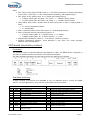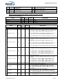
1
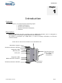
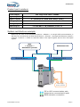
BRIO EN50155 Basic Remote I/O module Application note BRIO Extension & Ethernet redundancy P DOC BRIO 101E V01 This page is intentionally left blank Introduction BRIO is an Ethernet-based decentralized-remote input/output module designed to be embedded onboard rolling stock vehicles. BRIO is fully compliant with the EN50155 standard for railway systems. This application note describes all the necessary information to getting started with 2 BRIO with extension & Ethernet redundancy functionalities: hardware & software settings. Following User Manual for BRIO are available: User Manual “Hardware specifications & installation” P_DOC_BRIO_002E User Manual “Getting Started Software Guide” reference P_DOC_BRIO_003E Prerequisites It is necessary that the user has got technical knowledge in mechanical & electrical railway systems. Safety instructions Following symbols are used in this documentation in order to avoid user for potential risks: Risk of personal injury or damage to the equipment. Risk of an electrical hazard. Intellectual Property Leroy Automation owns the sole industrial and intellectual property of the products. The company Leroy Automation maintains and regularly improves its hardware and software products. The information contained in the document herein may be altered, removed or modified without prior notice, and this does not engage the responsibility of the company. This application note cannot be released, copied or duplicated in any forms without the written authorization issued by Leroy Automation. Contact Leroy Automation 35 Boulevard du Libre Echange 31650 SAINT-ORENS FRANCE +33 562 240 550 +33 562 240 555 mailto:[email protected] http://www.leroy-automation.com support technique : +33 562 240 546 mailto:[email protected] This page is intentionally left blank Table of Contents Chapter 1 Introduction ........................................................................................... 1 Contents ................................................................................................................ 1 Description ............................................................................................................. 1 Product part numbers .............................................................................................. 2 System architecture example .................................................................................... 2 Features ................................................................................................................. 3 Chapter 2 Communication protocols ....................................................................... 5 Contents ................................................................................................................ 5 EtherNet/IP Protocol ................................................................................................ 5 EtherNet/IP objects for Ethernet redundancy ....................................................... 5 UDP-based proprietary protocol ................................................................................. 6 Principles ........................................................................................................ 6 Available functions ........................................................................................... 6 BRIO’s input/output and status read command (0x03) ......................................... 7 Output value write command (0x11) .................................................................. 8 Chapter 3 Installation-wiring-settings .................................................................... 9 Contents ................................................................................................................ 9 Installation ............................................................................................................. 9 Wiring .................................................................................................................... 9 F48, M12 & subD9 connector pinout ................................................................... 9 SubD15 connector pinout : direct connection between BRIO 1 & BRIO 2 ................. 9 BRIO Settings ......................................................................................................... 9 Chapter 4 Monitoring examples ............................................................................ 11 Contents ...............................................................................................................11 Principle ................................................................................................................11 Software Installation ...............................................................................................12 Copalp T5 runtime setup..................................................................................12 STRATON IDE setup ........................................................................................12 STRATON Project List ......................................................................................12 EtherNet/IP scanner ................................................................................................12 Principle ........................................................................................................12 Configuration .................................................................................................12 Test ..............................................................................................................13 UDP manager .........................................................................................................14 Principle ........................................................................................................14 Configuration .................................................................................................14 Test ..............................................................................................................14 Introduction This page is intentionally left blank Introduction Chapter 1 Introduction Contents In this section, we will discuss the following topics: Hardware description, Product part numbers, System architecture examples, Features Description BRIO is a hardware unit fully compliant with the EN50155 standard, and it is designed to be integrated in embedded railway systems and subsystems. The system is composed by 2 BRIO R001, in order to manage redundancy on Ethernet communications. Guide rail for rack-mount chassis or for standalone use Standalone support Insertion/extraction handles Diagnostic LEDs Ethernet port F48 connectors for power supply and I/O signal connections serial port Diagnostic LEDs BRIO extension connector Insertion/extraction handles P DOC BRIO 101E V01 Protection enclosure Page 1 Introduction Product part numbers Power supply Full range from 24V to 110VDC Digital inputs 2 x 40 Digital outputs 2 x (8 Relays & 2 Solid State Relays (SSR)) Analog inputs - Analog outputs - Ethernet port 2 x IEEE 802.3 10/100Mbits/s base Tx System architecture example BRIO may be used as an EtherNet/IP device « adapter » or trough UDP communication; it will then be controlled by an Ethernet/IP device « scanner » through the Ethernet network; a device « scanner » is able to read the state of the input signals, and to drive its output signals. MPU « scanner » Automation process Ethernet 802.3 Maintenance PC Ethernet 802.3 Power supply, Sensors, Actuators EIP or UDP communication path Maintenance communication path BRIO extension connection P DOC BRIO 101E V01 Page 2 Introduction Features Variable power supply range from 24V to 110VDC 80 Digital inputs Variable power supply (full range from 24V to 110VDC) logical levels defined by software settings Individual filter parameters configurable 10mA fritting current Permanent auto-test on each input 20 Digital outputs SPDT (Single Pole Double Throw) type: relay outputs SSR (Solid state relay): isolated solid state ouputs, up-stream or down-stream loads, current monitoring on one output (optional) Command read-back feature on each output (optional) Input/Output management implemented in an FPGA device STM32 ARM Cortex-M3 microcontroller with FreeRTOS real time operating system Maximum delay between Ethernet and I/O: Between digital or analog inputs and Ethernet <10ms Between Ethernet and digital or analog outputs <15ms Ethernet protocols available: EtherNet/IP adapter UDP protocol BRIO too includes internal safety features as: a watchdog for monitoring the data communication between FPGA and microcontroller. a watchdog on the microcontroller. a safe communication (HDLC) between FPGA and microcontroller. P DOC BRIO 101E V01 Page 3 Introduction This page is intentionally left blank P DOC BRIO 101E V01 Page 4 Communication protocols Chapter 2 Communication protocols Contents In this section, we will discuss the following topics: EtherNet/IP Protocol UDP Protocol EtherNet/IP Protocol EtherNet/IP objects for Ethernet redundancy Following instances have been added in order to manage BRIO configuration with extension; for other EIP objects, refer to User Manual “Getting Started Software Guide” P_DOC_BRIO_003E Chapter 3. Instance number 102 103 104 Byte number 0 1 2 3 4 5 6 7 8 9 -20 21 22 23 24 25 26 27 28 29 -40 41 42 -0 1 2 7 DI8 DI16 DI24 DI32 DI40 DI48 DI56 DI64 DI72 DI80 -DIs8 DIs16 DIs24 DIs32 DIs40 DIs48 DIs56 DIs64 DIs72 DIs80 -DOs8 DOs16 --DO8 DO16 -- 0 reserved 1 P DOC BRIO 101E V01 6 DI7 DI15 DI23 DI31 DI39 DI47 DI55 DI63 DI71 DI79 -DIs7 DIs15 DIs23 DIs31 DIs39 DIs47 DIs55 DIs63 DIs71 DIs79 -DOs7 DOs15 --DO7 DO15 -reserved Bit number in the 5 4 DI6 DI5 DI14 DI13 DI22 DI21 DI30 DI29 DI38 DI37 DI46 DI45 DI54 DI53 DI62 DI61 DI70 DI69 DI78 DI77 --DIs6 DIs5 DIs14 DIs13 DIs22 DIs21 DIs30 DIs29 DIs38 DIs37 DIs46 DIs45 DIs54 DIs53 DIs62 DIs61 DIs70 DIs69 DIs78 DIs77 --DOs6 DOs5 DOs14 DOs13 ----DO6 DO5 DO14 DO13 --reserved reserved Byte word 3 2 DI4 DI3 DI12 DI11 DI20 DI19 DI28 DI27 DI36 DI35 DI44 DI43 DI52 DI51 DI60 DI59 DI68 DI67 DI76 DI75 --DIs4 DIs3 DIs12 DIs11 DIs20 DIs19 DIs28 DIs27 DIs36 DIs35 DIs44 DIs43 DIs52 DIs51 DIs60 DIs59 DIs68 DIs67 DIs76 DIs75 --DOs4 DOs3 DOs12 DOs11 DOs20 DOs19 --DO4 DO3 DO12 DO11 DO20 DO19 reserved reserved 1 0 DI2 DI1 DI10 DI9 DI18 DI17 DI26 DI25 DI34 DI33 DI42 DI41 DI50 DI49 DI58 DI57 DI66 DI65 DI74 DI73 --DIs2 DIs1 DIs10 DIs9 DIs18 DIs17 DIs26 DIs25 DIs34 DIs33 DIs42 DIs41 DIs50 DIs49 DIs58 DIs57 DIs66 DIs65 DIs74 DIs73 --DOs2 DOs1 DOs10 DOs9 DOs18 DOs17 --DO2 DO1 DO10 DO9 DO18 DO17 Digital Input Threshold Scanner monitoring timeout Page 5 Communication protocols With: DIx: Value of the filtered TOR input # x; the filtering function is defined according to the value « DIx filter » in the configuration assembly; (DI=Digital Input). AIx: Value of the analog input # x in points (AI=Analog Input): Voltage inputs (AI1 and AI2): 10,312V <-> -32768/+32767 points Current inputs (AI3 and AI4): 22,12mA <-> -32768/+32767 points DIsx, DOsx, AIsx, AOs1: Status value of each input (DIx or AIx) or output (DOx or AO1): 0= correct operational mode 1= defect/fault DOx: Command value of the TOR output # x (DO=Digital Output). AOx: Command value of the analog output # x: Current output (AO1_I): 0-32767 points <-> 0-20mA Voltage output (AO1_U): 0-32767 points <-> 0-10V Digital Input Threshold: value 0, 1 or 2 (24Vdc, 72Vdc or 110Vdc) Scanner monitoring timeout: value between 0 and 255, unit 10ms (timeout between 0ms and 2550ms). UDP-based proprietary protocol Principles The protocol used is request/response type based on UDP: the BRIO device responds to requests of another device connected on the Ethernet network. The data threads exchanged on this UDP protocol are defined as it follows: Available functions A large number of functions are available to set, to maintain and to control the BRIO device. For this application, only function code 0x03 & 0x11 are used. Request Code 0x01 0x02 Type Read Read 0x03 Read 0x04 0x05 0x06 0x07 0x10 0x11 Read Read Read Read Write Write 0x12 Write 0x15 Write Response of BRIO Description Code Description BRIO configuration 0x21 Returns the BRIO configuration settings Events log 0x22 Returns the events log Values and status of inputs/outputs, and Returns the values and status of inputs/outputs, 0x23 auto-tests results and auto-tests results Filtering values of digital inputs 0x24 Returns the filtering values of digital inputs Digital output configuration 0x25 Returns the digital output configuration Analog outputs configuration 0x26 Returns the analog outputs configuration KID settings 0x27 Returns the KID settings Filtering values of digital inputs 0x30 Returns the write status Digital and analogs outputs 0x31 Returns the write status IP configuration from the BRIO internal 0x32 Returns the write status memory Digital output properties from the BRIO 0x35 Returns the write status internal memory P DOC BRIO 101E V01 Page 6 Communication protocols Analog output properties from the BRIO internal memory Write KID settings Ethernet configuration from the BRIO Write internal memory Command BRIO reset 0x16 Write 0x17 0x18 0xAB Ox36 Returns the write status 0x37 Returns the write status 0x38 Returns the write status No returns BRIO’s input/output and status read command (0x03) Request word description: Name ID LENGTH RESERVED CRC Offset Size (byte) Value 0x00 0x02 0x04 0x06 2 2 2 2 0x03 0x02 0 0 Description Request ID code Length Reserved Reserved Response word description (BRIO): Name Size Value (byte) 0x00 0x02 2 2 0x23 0xD8 DISCRETE_IN_VALUE 0x04 20 - DISCRETE_IN_STATUS 0x18 20 - DISCRETE_OUT_VALUE 0x2C 8 - DISCRETE_OUT_STATUS 0x34 8 - reserved 0x3C 40 - PBIT_RESULT 0x64 2 - CBIT_RESULT 0x66 2 - IBIT_RESULT 0x68 2 - ID LENGTH Data Offset P DOC BRIO 101E V01 Description Request ID code Length Value of digital inputs Bit x of Byte y = input value number (8*y+x+1): 0=OFF, 1=ON Byte 0 = bit0 to bit7: values of BRIO 1 digital input 1 to 8. -------------Byte 4 = bit32 to bit39: values of BRIO 1 digital input 33 to 40. Byte 5 = bit0 to bit7: values of BRIO 2 digital input 1 to 8. -------------Byte 9 = bit32 to bit39: values of BRIO 2 digital input 33 to 40. -------------Status of digital inputs Bit x of Byte y = status of input number (8*y+x+1): 0=OK, 1=default. Byte 0 = bit0 to bit7: status of BRIO 1 digital input 1 to 8. -------------Byte 4 = bit32 to bit39: status of BRIO 1 digital input 33 to 40. Byte 5 = bit0 to bit7: status of BRIO 2 digital input 1 to 8. -------------Byte 9 = bit32 to bit39: status of BRIO 2 digital input 33 to 40. -------------Value of digital outputs Bit x of Byte y = value of output number (8*y+x+1): 0 = OFF, 1 = ON. Byte 0= bit0 to bit 7: value of BRIO 1 digital outputs 1 à 8 Byte 1= bit0 to bit 1: value of BRIO 1 digital outputs 9 à 10 Byte 2= bit0 to bit 7: value of BRIO 2 digital outputs 1 à 8 Byte 3= bit0 to bit 1: value of BRIO 2 digital outputs 9 à 10 -------------Status of digital outputs Bit x of Byte y = status of output number (8*y+x+1): 0=OK, 1=default. Byte 0= bit0 to bit 7: status of BRIO 1 digital outputs 1 à 8 Byte 1= bit0 to bit 1: status of BRIO 1 digital outputs 9 à 10 Byte 2= bit0 to bit 7: status of BRIO 2 digital outputs 1 à 8 Byte 3= bit0 to bit 1: status of BRIO 2 digital outputs 9 à 10 -------------reserved Start-up test results (refer to chapter 2) Byte0 = [ROM_DEF(bit0), RAM_DEF, NVM_DEF, FPGA_DEF, TEMP_DEF, ETHER_DEF, KID _DEF, EXT_CONF_DEF (bit7)] Byte1 = [MOD_TYPE_DEF(bit0), FACTORY_DEF, res, res, res, res, res,res(bit7)] Continuous tests results (refer to chapter 2) Byte0 = [CPU_DEF(bit0), FPGA_DEF, ETHER_DEF, TEMP_DEF, EIP_DEF, DISC_IN_DEF, DISC_OUT_DEF,ANA_IN_DEF(bit7)] Byte1 = [ANA_OUT_DEF(bit0), res, res, res, res, res, res,res(bit7)] Tests results on request (refer to chapter 2) Byte0 = [RAM_DEF(bit0), res, res, res, res, res, res, res (bit7)] Byte1 = [res (bit0), res, res, res, res, res, res,res(bit7)] Page 7 Communication protocols CONNECTION_EIP_STATE 0xDA 1 - Reserved 0xDB 1 0 RESERVED CRC 0xDC 0xDE 2 2 0 0 1 = EIP connection enabled 2 = no EIP connection Reserved Reserved Output value write command (0x11) Request word description: Offset Size (byte) Value 0x00 0x02 0x04 2 2 4 0x11 0x10 - DISCRETE_OUT_VALUE 0x08 8 - ANALOG_OUTPUT_VALUE 0x10 4 0x14 0x16 2 2 Name ID LENGTH Data CMD RESERVED CRC Description Request ID code Length 0x00 = digital and analog output write 0x01 = digital output write 0x02 = analog output write Value of 10 digital outputs is contained in 2 bytes Bit x of Byte y = output value number (8*y+x+1): 0 = OFF, 1 = ON. Byte0 = bit0 to bit 7: value of digital outputs 1 to 8 Byte1 = bit0 to bit 1: value of digital outputs 9 to 10 BRIO 1 : offset 8 & 9 BRIO 2 : offset A & B Analog output value to write Byte0- Byte1 = value of analog output 1 Reserved Reserved 0 0 Response word description (BRIO): Name ID LENGTH STATUS RESERVED CRC P DOC BRIO 101E V01 Offset Size Value (byte) 0x00 0x02 0x04 2 2 4 0x31 0x04 0 0x08 0x0A 2 2 0 0 Description Request ID code Length 0 = write completed 1 = write failure Reserved Reserved Page 8 Installation-wiring-settings Chapter 3 Installation-wiring-settings Contents In this section, we will discuss the following topics: Installation Wiring Settings Installation BRIO shall be mounted on the standalone double support designed for it. It receives F48 connectors for power supply and IO on the rear panel. For mounting or dismounting, refer to User Manual “Hardware specifications & installation” P_DOC_BRIO_002E Chapter 4. Wiring F48, M12 & subD9 connector pinout Pinout is described in P_DOC_BRIO_002E documentation Chapter3. SubD15 connector pinout : direct connection between BRIO 1 & BRIO 2 Both BRIO shall have a direct connection between them. This direct connection is done through each BRIO SubD15 connector. This connection is used: to exchange data to fix an address to each BRIO on this local network: then the subD15 connectors shall not be reversed. BRIO Settings Settings are saved in BRIO NVM (Non Volatile Memory). They can be set or modified through BRIO subD9 RS232 link: refer to User Manuel Getting Started Software Guide P_DOC_BRIO_003E Chapter 5. P DOC BRIO 101E V01 Page 9 Installation-wiring-settings Use command “j” then command “a” in order to read all NVM settings. Some settings are different between BRIO 1 and BRIO 2: BRIO 1 NVM configuration: BRIO 2 NVM configuration: Differences are as following: “IP address”: o BRIO 1 is set to 192.168.1.101 o BRIO 2 is set to 192.168.2.102 “Module type”: o BRIO 1 is set to “0” (master): master shall have address 1 coded in its connected subD15. o BRIO 2 is set to “1” (slave): slave shall have address 2 coded in its connected subD15. P DOC BRIO 101E V01 Page 10 Monitoring examples Chapter 4 Monitoring examples Contents In this section, we will discuss the following topics: Principle Software Installation EtherNet/IP scanner UDP manager Principle Each BRIO will communicate with one PC through one Ethernet network. For this, the PC will be fitted with: Specific hardware: 2 Ethernet ports, configured as following: o First Ethernet port: IP address 192.168.1.10 o Second Ethernet port: IP address 192.168.2.10 Specific Software: T5 runtime for Windows PC from the Copalp Company: this runtime will run projects developed with “STRATON” (IEC61131 IDE from Copalp). P DOC BRIO 101E V01 Page 11 Monitoring examples 2 projects have been developed with STRATON IDE in order to test both communication types (EtherNet/IP & UDP). Software Installation We need to install several softwares on the PC: T5 runtime STRATON IDE After STRATON installation, we will restore in STRATON the BRIO2E list of projects developed for these tests. Copalp T5 runtime setup Execute the following setup file “STRATON.T5.setup.8.7.build.2.exe”. This software is protected, but you can run it for demonstrations during 15 minutes. If you need more, you have to stop & start it. STRATON IDE setup Execute the following setup file “STRATON.IDE.setup.8.7.build.2.exe”. This software is protected, but for demonstrations you can run it and build projects containing less 40 IO variables. STRATON Project List The complete project list is contained in a zip file: “BRIO2E.zip” “BRIO2E_EIP1”: project with EtherNet/IP communication. “BRIO2E_UDP1”: project with UDP communication. In STRATON Editor 8.7 (IDE), select menu “File”/”Open Project List”/”From Zip”: select the zip file: “BRIO2E.zip”, and validate. EtherNet/IP scanner Principle The project “BRIO2E_EIP1” enables 1 EtherNet/IP connection with each BRIO: Configuration The fieldbus Configurations tool allows to define the complete EtherNet/IP communication on both Ethernet networks with all project variables linked to: P DOC BRIO 101E V01 Page 12 Monitoring examples Test The project BRIO2E_EIP1 shall have been selected, then: connect you to the T5 Runtime with the “On line” button download the project code into the T5 runtime The Graphic window “Valid_EIP” allows to monitor the both BRIO. Nominal case: Network 2 disconnected: management is still complete. P DOC BRIO 101E V01 Page 13 Monitoring examples Network 2 disconnected & local link between both BRIO disconnected: management is still OK only on BRIO1. UDP manager Principle The project “BRIO2E_UDP1” enables 1 UDP connection with each BRIO: Configuration The Communication is programmed with straton functions allowing to manage UDP frames: Test The project BRIO2E_UDP1 shall have been selected, then: connect you to the T5 Runtime with the “On line” button download the project code into the T5 runtime The Graphic window “Valid_UDP” allows to monitor each BRIO. P DOC BRIO 101E V01 Page 14 Monitoring examples Nominal case: Network 2 disconnected: management is still complete. P DOC BRIO 101E V01 Page 15 Monitoring examples Network 2 disconnected & local link between both BRIO disconnected: management is still OK only on BRIO1. P DOC BRIO 101E V01 Page 16