1
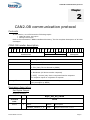
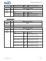
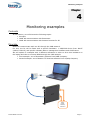
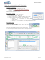
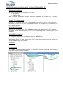
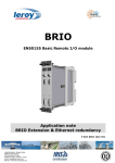
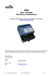
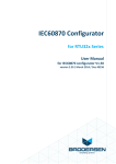
BRIO EN50155 Basic Remote I/O module Application note CAN2.0B communication P DOC BRIO 102E V01 This page is intentionally left blank Introduction BRIO is a decentralized-remote input/output module designed to be embedded onboard rolling stock vehicles. BRIO is fully compliant with the EN50155 standard for railway systems. This application note describes all the necessary information to getting started with 1 BRIO with CAN 2.0B functionalities: hardware & software settings. Following User Manual for BRIO are available: User Manual “Hardware specifications & installation” P_DOC_BRIO_002E User Manual “Getting Started Software Guide” reference P_DOC_BRIO_003E Prerequisites It is necessary that the user has got technical knowledge in mechanical & electrical railway systems. Safety instructions Following symbols are used in this documentation in order to avoid user for potential risks: Risk of personal injury or damage to the equipment. Risk of an electrical hazard. Intellectual Property Leroy Automation owns the sole industrial and intellectual property of the products. The company Leroy Automation maintains and regularly improves its hardware and software products. The information contained in the document herein may be altered, removed or modified without prior notice, and this does not engage the responsibility of the company. This application note cannot be released, copied or duplicated in any forms without the written authorization issued by Leroy Automation. Contact Leroy Automation 35 Boulevard du Libre Echange 31650 SAINT-ORENS FRANCE +33 562 240 550 +33 562 240 555 mailto:[email protected] http://www.leroy-automation.com support technique : +33 562 240 546 mailto:[email protected] This page is intentionally left blank Table of Contents Chapter 1 Introduction ........................................................................................... 1 Contents ................................................................................................................ 1 Description ............................................................................................................. 1 Product part numbers .............................................................................................. 2 System architecture example .................................................................................... 2 Features ................................................................................................................. 3 Chapter 2 CAN2.0B communication protocol ........................................................... 5 Contents ................................................................................................................ 5 CAN2.0B header description ...................................................................................... 5 Messages description ............................................................................................... 5 Set Digital Output ............................................................................................ 5 Get Digital Input .............................................................................................. 6 Chapter 3 Installation-wiring-settings .................................................................... 7 Contents ................................................................................................................ 7 Installation ............................................................................................................. 7 Wiring .................................................................................................................... 7 F48 IO connector pinout ................................................................................... 7 CAN2.0 B subD9 connector pinout (SubD9 Male) ................................................. 7 BRIO Settings ......................................................................................................... 7 Chapter 4 Monitoring examples .............................................................................. 9 Contents ................................................................................................................ 9 Principle ................................................................................................................. 9 CAN2.0B communication with Busmaster ..................................................................10 Software Installation .......................................................................................10 Busmaster settings .........................................................................................10 Busmaster tests .............................................................................................10 CAN2.0B communication with Straton Runtime for PC .................................................11 Software Installation .......................................................................................11 Copalp T5 runtime setup..................................................................................11 STRATON IDE setup ........................................................................................11 STRATON Project List ......................................................................................11 Principle ........................................................................................................11 Configuration .................................................................................................11 Test ..............................................................................................................12 Introduction This page is intentionally left blank Introduction Chapter 1 Introduction Contents In this section, we will discuss the following topics: Description, Product part numbers, System architecture examples, Features Description BRIO is a hardware unit fully compliant with the EN50155 standard, and it is designed to be integrated in embedded railway systems and subsystems. Guide rail for rack-mount chassis or for standalone use Insertion/extraction handles Label F48 connectors for power supply and I/O signal connections Diagnostic LEDs Ethernet port Serial port CAN port Insertion/extraction handles Protection enclosure P DOC BRIO 101E V01 Page 1 Introduction Product part numbers Power supply Full range from 24V to 110VDC Digital inputs 40 Digital outputs 8 Relays & 2 Solid State Relays (SSR) Analog inputs 2 currents & 2 voltages Analog outputs 1 current or voltage Ethernet port IEEE 802.3 10/100Mbits/s base Tx CAN port CAN2.0B System architecture example BRIO may be used as a CAN2.0B IO device; it will then be controlled by another CAN2.0B device « scanner » through the CAN network; the « scanner » device will be able to read the state and values of the input signals, and to drive its output signals. MPU « master » Automation process CAN 2.0B Power supply, Sensors, Actuators Power supply, Sensors, Actuators Power supply, Sensors, Actuators CAN2.0B communication P DOC BRIO 101E V01 Page 2 Introduction Features Variable power supply range from 24V to 110VDC 40 Digital inputs Variable power supply (full range from 24V to 110VDC) logical levels defined by software settings Individual filter parameters configurable 10mA fritting current Permanent auto-test on each input 10 Digital outputs SPDT (Single Pole Double Throw) type: relay outputs SSR (Solid state relay): isolated solid state ouputs, up-stream or down-stream loads, current monitoring on one output (optional) Command read-back feature on each output (optional) Input/Output management implemented in an FPGA device STM32 ARM Cortex-M3 microcontroller with FreeRTOS real time operating system Maximum delay between Ethernet and I/O: Between digital or analog inputs and Ethernet <10ms Between Ethernet and digital or analog outputs <15ms Protocols available: CAN port: CAN2.0B protocol Ethernet port: o EtherNet/IP adapter o UDP protocol BRIO too includes internal safety features as: a watchdog for monitoring the data communication between FPGA and microcontroller. a watchdog on the microcontroller. a safe communication (HDLC) between FPGA and microcontroller. P DOC BRIO 101E V01 Page 3 Introduction This page is intentionally left blank P DOC BRIO 101E V01 Page 4 CAN2.0B communication protocol Chapter 2 CAN2.0B communication protocol Contents In this section, we will discuss the following topics: CAN2.0B header description Messages description Refer to documentation “BRIO CAN Data dictionary” for the complete description of all CAN messages. CAN2.0B header description 2 8 2 7 2 6 2 5 2 4 2 3 2 2 2 1 2 0 1 9 1 8 1 7 1 6 1 5 1 4 1 3 1 2 1 1 src Function Code 1 0 9 8 7 6 5 4 3 2 1 dest Module addr Name Description Function code Used to identify function requested Module Address - src Is the source of emitter Message ID 0: TCU (Only TCU is allowed by BRIO) Module Address - dest For request is the destination 0: Broadcast (all device send a response) [1-255]: unicast (only device requested send a response For response equal to originator of request. Message ID Free running counter, incremented by one at each new message (only managed by BRIO) Messages description Set Digital Output Request message : RQST_SET_DO_VALUE Function code DLC 0x101 2 P DOC BRIO 101E V01 DATA Name Offset Description DIGITAL_OUTPUT_1_8 0x00 Output value from 1 to 8 Page 5 0 CAN2.0B communication protocol DIGITAL_OUTPUT_9_10 0X01 Output value from 9 to 10 BRIO response message RESP_SET_DO_VALUE Function code DLC 0x201 2 DATA Name Offset Description DIGITAL_OUTPUT_1_8 0x00 Output value from 1 to 8 DIGITAL_OUTPUT_9_10 0X01 Output value from 9 to 10 Get Digital Input Request message : RQST_SET_AO_VALUE Function code DLC DATA 0x103 0 None BRIO response message RESP_SET_AO_VALUE Function code DLC 0x203 2 DATA Name Offset Description DIGITAL_INPUT_1_8 0x00 Digital input from 1 to 8 (0:not activated,1:activated) DIGITAL_INPUT_9_16 0X01 Digital input from 9 to 16 (0:not activated,1:activated) DIGITAL_INPUT_17_24 0X02 Digital input from 17 to 24 (0:not activated,1:activated) DIGITAL_INPUT_25_32 0X03 Digital input from 25 to 32 (0:not activated,1:activated) DIGITAL_INPUT_33_40 0X04 Digital input from 33 to 40 (0:not activated,1:activated) P DOC BRIO 101E V01 Page 6 Installation-wiring-settings Chapter 3 Installation-wiring-settings Contents In this section, we will discuss the following topics: Installation Wiring Settings Installation BRIO shall be mounted on the standalone support designed for it. It receives F48 connectors for power supply and IO on the rear panel. For mounting or dismounting, refer to User Manual “Hardware specifications & installation” P_DOC_BRIO_002E Chapter 4. Wiring F48 IO connector pinout Pinout is described in P_DOC_BRIO_002E documentation Chapter3. CAN2.0 B subD9 connector pinout (SubD9 Male) Pinout is as following according to ISO 11898-2. SubD9 Signal 2 CAN low 3 CAN ground 7 CAN high BRIO Settings Settings are saved in BRIO NVM (Non Volatile Memory). They can be set or modified through BRIO subD9 RS232 link: refer to User Manuel Getting Started Software Guide P_DOC_BRIO_003E Chapter 5. Use command “j” then command “a” in order to read all NVM settings. P DOC BRIO 101E V01 Page 7 Installation-wiring-settings Setting for CAN management: “device id” or CAN address: set to 4 in this example. P DOC BRIO 101E V01 Page 8 Monitoring examples Chapter 4 Monitoring examples Contents In this section, we will discuss the following topics: Principle CAN2.0B communication with Busmaster CAN2.0B communication with Straton Runtime for PC Principle BRIO will communicate with one PC through the CAN network. For this, the PC will be fitted with a specific hardware: 1 USB/CAN device from IXXAT (USB-to-CAN V2) and specific software able to manage this hardware and CAN frames. We will explain 2 examples with 2 different softwares in order to drive this hardware on the laptop and then to monitor BRIO through the CAN network: First example: use of Busmaster software from RBEI Company. Second example: use of Straton T5 Runtime software from Copalp Company. Power supply, Sensors, Actuators P DOC BRIO 101E V01 Page 9 Monitoring examples CAN2.0B communication with Busmaster Software Installation We need to install Busmaster software on the PC: Download it : http://rbei-etas.github.io/busmaster/ Install it : BUSMASTER_Installer_Ver_2.x.y.exe After Busmaster installation, start it. Busmaster settings Do the following settings in the “CAN” menu: Driver selection: select “IXXAT VCI” Channel configuration : for Baudrate kBit/s, select « 125 » Configure Transmission Messages : add 2 messages : o Message 1 : ID « 0x1010400 » for writing BRIO digital outputs o Message 2 : ID « 0x1030400 » for reading BRIO digital inputs Busmaster tests Connect Busmaster to IXXAT device: menu “CAN” and “Connect” or Connect button. Then select one Message and click on the “Send” button. The send message and BRIO response appear in Message Window. P DOC BRIO 101E V01 Page 10 Monitoring examples CAN2.0B communication with Straton Runtime for PC Software Installation We need to install several softwares on the PC: T5 runtime STRATON IDE After STRATON installation, we will restore in STRATON the BRIO2E list of projects developed for this example. Copalp T5 runtime setup Execute the following setup file “STRATON.T5.setup.8.7.build.2.exe”. This software is protected, but you can run it for demonstrations during 15 minutes. If you need more, you have to stop & start it. STRATON IDE setup Execute the following setup file “STRATON.IDE.setup.8.7.build.2.exe”. This software is protected, but for demonstrations you can run it and build projects containing less 40 IO variables. STRATON Project List The complete project list is contained in a zip file: “BRIO2E.zip” “BRIO_CAN”: project with CAN2.0 communication. In STRATON Editor 8.7 (IDE), select menu “File”/”Open Project List”/”From Zip”: select the zip file: “BRIO2E.zip”, and validate. Principle The project “BRIO_CAN” enables 1 CAN2.0B connection with one BRIO. Configuration The fieldbus Configurations tool allows to define the complete CAN2.0B communication with each project variables linked to: P DOC BRIO 101E V01 Page 11 Monitoring examples Test The project BRIO_CAN shall have been selected, then: connect you to the T5 Runtime with the “On line” button download the project code into the T5 runtime The Graphic windows “Valid_CAN” or “Train_CAN” allows to monitor the BRIO. Graphic “Valid_CAN”: Graphic “Train_CAN”: P DOC BRIO 101E V01 Page 12