1
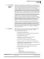
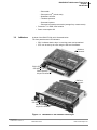
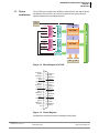
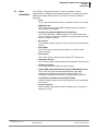
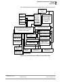
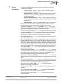
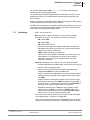
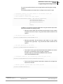
DNA/DNR-CT-602 — User Manual 32-bit Interruptable Counter/Timer Layer with Differential Input/Outputs for the PowerDNA Cube and PowerDNR RACKtangle Release 4.5 March 2012 PN Man-DNx-CT-602-312 © Copyright 1998-2012 United Electronic Industries, Inc. All rights reserved. No part of this publication may be reproduced, stored in a retrieval system, or transmitted, in any form by any means, electronic, mechanical, by photocopying, recording, or otherwise without prior written permission. Information furnished in this manual is believed to be accurate and reliable. However, no responsibility is assumed for its use, or for any infringement of patents or other rights of third parties that may result from its use. All product names listed are trademarks or trade names of their respective companies. See the UEI website for complete terms and conditions of sale: http://www.ueidaq.com/cms/terms-and-conditions/ Contacting United Electronic Industries Mailing Address: 27 Renmar Avenue Walpole, MA 02081 U.S.A. For a list of our distributors and partners in the US and around the world, please see http://www.ueidaq.com/partners/ Support: Telephone: Fax: (508) 921-4600 (508) 668-2350 Also see the FAQs and online “Live Help” feature on our web site. Internet Support: Support: Web-Site: FTP Site: [email protected] www.ueidaq.com ftp://ftp.ueidaq.com Product Disclaimer: WARNING! DO NOT USE PRODUCTS SOLD BY UNITED ELECTRONIC INDUSTRIES, INC. AS CRITICAL COMPONENTS IN LIFE SUPPORT DEVICES OR SYSTEMS. Products sold by United Electronic Industries, Inc. are not authorized for use as critical components in life support devices or systems. A critical component is any component of a life support device or system whose failure to perform can be reasonably expected to cause the failure of the life support device or system, or to affect its safety or effectiveness. Any attempt to purchase any United Electronic Industries, Inc. product for that purpose is null and void and United Electronic Industries Inc. accepts no liability whatsoever in contract, tort, or otherwise whether or not resulting from our or our employees' negligence or failure to detect an improper purchase. Specifications in this document are subject to change without notice. Check with UEI for current status. DNA/DNR-CT-602 Counter/Timer Layer Contents Table of Contents Chapter 1 Introduction .................................................... 3 1.1 Organization of Manual. . . . . . . . . . . . . . . . . . . . . . . . . . . . . . . . . . . . . . . . . . . . . . . . 3 1.2 The CT-602 Interface Board . . . . . . . . . . . . . . . . . . . . . . . . . . . . . . . . . . . . . . . . . . . . 5 1.3 Features . . . . . . . . . . . . . . . . . . . . . . . . . . . . . . . . . . . . . . . . . . . . . . . . . . . . . . . . . . . 5 1.4 Indicators . . . . . . . . . . . . . . . . . . . . . . . . . . . . . . . . . . . . . . . . . . . . . . . . . . . . . . . . . . 6 1.5 Device Architecture. . . . . . . . . . . . . . . . . . . . . . . . . . . . . . . . . . . . . . . . . . . . . . . . . . . 7 1.6 Layer Capabilities . . . . . . . . . . . . . . . . . . . . . . . . . . . . . . . . . . . . . . . . . . . . . . . . . . . 8 1.7 1.7.1 1.7.2 1.7.3 1.7.4 1.7.5 Device Description . . . . . . . . . . . . . . . . . . . . . . . . . . . . . . . . . . . . . . . . . . . . . . . . . . Terminology . . . . . . . . . . . . . . . . . . . . . . . . . . . . . . . . . . . . . . . . . . . . . . . . . . Counter Register (CR) Counting Modes . . . . . . . . . . . . . . . . . . . . . . . . . . . . CR Output Modes . . . . . . . . . . . . . . . . . . . . . . . . . . . . . . . . . . . . . . . . . . . . . CR Input Modes . . . . . . . . . . . . . . . . . . . . . . . . . . . . . . . . . . . . . . . . . . . . . . . Termination . . . . . . . . . . . . . . . . . . . . . . . . . . . . . . . . . . . . . . . . . . . . . . . . . . 10 11 12 12 12 13 Chapter 2 Programming with the High Level API . . . . . . . . . . . . . . . . . . . . . . . . . . . . . . 14 2.1 Creating a Session . . . . . . . . . . . . . . . . . . . . . . . . . . . . . . . . . . . . . . . . . . . . . . . . . . 14 2.2 2.2.1 2.2.2 2.2.3 Configuring the Resource String. . . . . . . . . . . . . . . . . . . . . . . . . . . . . . . . . . . . . . . . Configuring a Counter-Timer for Input . . . . . . . . . . . . . . . . . . . . . . . . . . . . . . Configuring a Counter-Timer for Output . . . . . . . . . . . . . . . . . . . . . . . . . . . . Configuring Digital I/O . . . . . . . . . . . . . . . . . . . . . . . . . . . . . . . . . . . . . . . . . . 2.3 Configuring the Timing . . . . . . . . . . . . . . . . . . . . . . . . . . . . . . . . . . . . . . . . . . . . . . . 17 2.4 2.4.1 2.4.2 2.4.3 Data Aquisition . . . . . . . . . . . . . . . . . . . . . . . . . . . . . . . . . . . . . . . . . . . . . . . . . . . . . Reading Data from Counter . . . . . . . . . . . . . . . . . . . . . . . . . . . . . . . . . . . . . . Reading Data from Digital IO . . . . . . . . . . . . . . . . . . . . . . . . . . . . . . . . . . . . . Writing Data to the Digital IO . . . . . . . . . . . . . . . . . . . . . . . . . . . . . . . . . . . . . 2.5 Cleaning-up the Session. . . . . . . . . . . . . . . . . . . . . . . . . . . . . . . . . . . . . . . . . . . . . . 19 14 14 16 17 18 18 18 18 Chapter 3 Programming with the Low Level API . . . . . . . . . . . . . . . . . . . . . . . . . . . . . . 20 3.1 Data . . . . . . . . . . . . . . . . . . . . . . . . . . . . . . . . . . . . . . . . . . . . . . . . . . . . . . . . . . . . . 20 3.2 Configuration. . . . . . . . . . . . . . . . . . . . . . . . . . . . . . . . . . . . . . . . . . . . . . . . . . . . . . . 20 3.3 Channel List . . . . . . . . . . . . . . . . . . . . . . . . . . . . . . . . . . . . . . . . . . . . . . . . . . . . . . . 20 3.4 Layer-specific Commands & Parameters . . . . . . . . . . . . . . . . . . . . . . . . . . . . . . . . . 20 © Copyright 2012 United Electronic Industries, Inc. Tel: 508-921-4600 Date: March 2012 www.ueidaq.com Vers: 4.5 DNx-CT-602-ManualTOC.fm 1 DNA/DNR-CT-602 Counter/Timer Layer Figures List of Figures Chapter 1 – Introduction . . . . . . . . . . . . . . . . . . . . . . . . . . . . . . . . . . . . . . . . . . . . . . . . . . . . . 1 1-1 DNA/DNR-CT-602 Counter/Timer Layer ...................................................................... 6 1-2 Block Diagram of CT-602.............................................................................................. 7 1-3 Pinout Diagram ............................................................................................................. 7 1-4 Internal Structure of Each Counter/Timer Unit.............................................................. 9 1-5 TPPM Operation Clock Diagram Example................................................................. 13 1-6 Settable Termination Circuit Diagram ......................................................................... 13 © Copyright 2012 United Electronic Industries, Inc. Tel: 508-921-4600 Date: March 2012 www.ueidaq.com Vers: 4.5 DNx-CT-602-ManualLOF.fm 2 DNA/DNR-CT-602 Counter/Timer Layer Chapter 1 Introduction Chapter 1 Introduction This document outlines the feature-set of the DNR- and DNA-CT-602 layer and how to use it for counter/timer applications. 1.1 Organization of Manual © Copyright 2012 United Electronic Industries, Inc. This CT-602 User Manual is organized as follows: • Introduction This section provides an overview of the Counter-Timer Series board features, the various models available and what you need to get started. • The CT-602 Layer This chapter provides an overview of the CT-602 features, device architecture, and connectivity. • Programming with the High-Level API This chapter provides an overview of the how to create a session, configure the session, and format relevant data with the Framework API. • Programming with the Low-Level API Describes low-level API commands for configuring and using the CT602 series layer operating modes. • Appendix A - Accessories This appendix provides a list of accessories available for use with the DNx-CT-602 interface board. • Index This is an alphabetical listing of the topics covered in this manual. Tel: 508-921-4600 Date: March 2012 www.ueidaq.com Vers: 4.5 DNx-CT-602 Chap1x.fm 3 DNA/DNR-CT-602 Counter/Timer Layer Chapter 1 Introduction Manual Conventions To help you get the most out of this manual and our products, please note that we use the following conventions: Tips are designed to highlight quick ways to get the job done or to reveal good ideas you might not discover on your own. NOTE: Notes alert you to important information. CAUTION! Caution advises you of precautions to take to avoid injury, data loss, and damage to your boards or a system crash. Text formatted in bold typeface generally represents text that should be entered verbatim. For instance, it can represent a command, as in the following example: “You can instruct users how to run setup using a command such as setup.exe.” Text formatted in fixed typeface generally represents source code or other text that should be entered verbadim into the source code, initialization, or other file. Examples of Manual Conventions Before plugging any I/O connector into the Cube or RACKtangle, be sure to remove power from all field wiring. Failure to do so may cause severe damage to the equipment. Usage of Terms Throughout this manual, the term “Cube” refers to either a PowerDNA Cube product or to a PowerDNR RACKtangle rack mounted system, whichever is applicable. The term DNR is a specific reference to the RACKtangle, DNA to the PowerDNA I/O Cube, and DNx to refer to both. © Copyright 2012 United Electronic Industries, Inc. Tel: 508-921-4600 Date: March 2012 www.ueidaq.com Vers: 4.5 DNx-CT-602 Chap1x.fm 4 DNA/DNR-CT-602 Counter/Timer Layer Chapter 1 Introduction 1.2 The CT-602 Interface Board The DNA-CT-602 and DNR-CT-602 are differential counter/timer interfaces for UEI’s “Cube” and RACKtangle I/O chassis respectively. The DNA/DNR versions are electrically identical and provide four independent 32-bit channels, each one having overvoltage protection and opto-isolation. They perform up/down counting in a number of flexible modes using values from a Load Register and two Compare Registers. They can act as an event counter, perform width/ period measurements and run in quadrature-encoder mode where the user sets the direction of the counting. For output modes, the layer offers 1-shot and Universal PWM operation. It also provides edge detection on the ClockIn and Gate pins. The layer is available in two versions: the DNA-CT-602 for mounting in UEI Cube products, and the DNR-CT-602 for insertion into the UEI RACKtangle and HalfRACK chassis. The DNx-CT-602 is physically a two-board module composed of one of two types of base boards (one for the DNA version and another for the DNR version) plus an CT-602-specific daughter board. The DNA and DNR are functionally the same except for the bus connectors used. The DNx-CT-602 is software compatible with the DNx-CT-601 except for the additional commands which configure and control the Trigger Output pins. Software for the DNx-CT-602 is provided as part of the UEI Framework. Framework provides a comprehensive, yet easy-to-use, API that is compatible with all popular Windows programming languages and that also supports programmers using Linux and most realtime operating systems such as QNX, RTX, or RT Linux. Also, UEI Framework can be used for creating applications in LabVIEW, MATLAB/SImulink, DASYLab, or any application that supports ActiveX or OPC servers. 1.3 Features The CT-602 counter/timer layer is based on the PL-601 programmable logic layer. It contains a specific counter-timer implementation on FPGA. The CT-602 has the following features: • 4 independent counter/timer units • Fully differential I/O using at RS-422 / RS-485 logic voltage levels • Clock and Gate inputs for every counter • Trigger output for every counter • Gate input has programmable polarity, edge sensitive • Start/pause/stop all channels simultaneously • 32-bit prescaler per channel; quadrature encoder support • Multiple period counter (to 232 periods) with accumulated results • Works with either internal (66 MHz) or external ( 16.5 MHz) timebase; 132MHz timebase for measurement modes • 256 x 32-bit Input FIFO and 256 x 32-bit Output FIFO on each counter • Debouncing/glitch removal on external clock and gate inputs • 16 interrupt sources on every counter • 10 Counting modes: – Timer – PWM generator – Continuously updated PWM generator (buffered) – Bin counter (number of pulses in specified time interval) © Copyright 2012 United Electronic Industries, Inc. Tel: 508-921-4600 Date: March 2012 www.ueidaq.com Vers: 4.5 DNx-CT-602 Chap1x.fm 5 DNA/DNR-CT-602 Counter/Timer Layer Chapter 1 Introduction – Pulse width – Pulse period (232 periods max) – Quadrature encoder – Timebase operation – Generate N-pulses – Pulse-period measurement mode (average freq. measurement) 1.4 Indicators • Protection 7 kV ESD, 350V isolation • Power consumption 2W A photo of the DNA-CT-602 unit is illustrated below. The front panel has two LED indicators: • RDY: indicates that the layer is receiving power and operational. • STS: can be set by the user using the low-level framework. DNA bus connector RDY LED STS LED DB-62 (female) 62-pin I/O connector DNR bus connector RDY LED STS LED DB-62 (female) 62-pin I/O connector Figure 1-1. DNA/DNR-CT-602 Counter/Timer Layer © Copyright 2012 United Electronic Industries, Inc. Tel: 508-921-4600 Date: March 2012 www.ueidaq.com Vers: 4.5 DNx-CT-602 Chap1x.fm 6 DNA/DNR-CT-602 Counter/Timer Layer Chapter 1 Introduction Device Architecture The CT-602 layer consists of two PCBs: the main board PL-60x and the power and isolation board PL-601. All inputs and outputs of this counter-timer are optically isolated and overvoltage protected. 66 MHz Internal Input Clock CLKIN3 CLKOUT3 GATE3 TRIGOUT3v Optical Isolaton TRIGOUT0 C/T Unit0 Optical Isolaton GATE0 Overvoltage Protection CLKOUT0 Control Logic Overvoltage Protection CLKIN0 C/T Unit3 32-bit 66-MHz Bus 1.5 Sync Bus Input FIFO Output FIFO Figure 1-2. Block Diagram of CT-602 CLKOUT(0)+ GATE(0)+ TRIGOUT(0)+ CLKIN(0)+ GND(0) CLKOUT(1)+ GATE(1)+ TRIGOUT(1)+ CLKIN(1)+ CLKOUT(2)+ GATE(2)+ TRIGOUT(2)+ CLKIN(2)+ GND(2) CLKOUT(3)+ GATE(3)+ TRIGOUT(3)+ CLKIN(3)+ Rsvd 1 2 3 4 5 6 7 8 9 10 11 12 13 14 15 16 17 18 19 20 21 22 23 24 25 26 27 28 29 30 31 32 33 34 35 36 37 CLKOUT(0)GATE(0)TRIGOUT(0)CLKIN(0)GND(1) CLKOUT(1)GATE(1)TRIGOUT(1)CLKIN(1)CLKOUT(2)GATE(2)TRIGOUT(2)CLKIN(2)GND(3) CLKOUT(3)GATE(3)TRIGOUT(3)CLKIN(3)- Figure 1-3. Pinout Diagram All signals are referenced relative to isolated ground (IGND). © Copyright 2012 United Electronic Industries, Inc. Tel: 508-921-4600 Date: March 2012 www.ueidaq.com Vers: 4.5 DNx-CT-602 Chap1x.fm 7 DNA/DNR-CT-602 Counter/Timer Layer Chapter 1 Introduction 1.6 Layer Capabilities © Copyright 2012 United Electronic Industries, Inc. The CT-602 is a complex layer with 11 modes of operation. It can be programmed for a single-point and buffered operations. In single-point mode, it performs immediate measurements or one-time or continuous waveform generation. • Timer The CT-602 measures time interval or generates clocks on the output • PWM Generator The CT-602 generates pulse-width-modulation waveform based on values stored in its registers. • Continuously Updated PWM Generator (Buffered) The CT-602 generates a PWM waveform. On a selected timebase counter, it takes new settings for PWM from an internal buffer and loads them into compare registers. • Bin Counter The CT-602 bin counter counts a number of pulses in the specified time interval • Pulse Width The CT-602 counter measures pulse width in a number of base frequency clocks • Pulse Period The CT-602 counter measures pulse periods (232 periods max) • Quadrature Encoder The CT-602 measures relative position from quadrature encoder sensor • Timebase Operation The CT-602 provides timebase for other counters • Output PWM Signal While Performing Pulse-Width Measurement The CT-602 can output a pulse-width-modulated signal while simultaneously performing a pulse-width measurement. This functionality is especially useful with an magnetorestrictive sensor. • Timed Pulse Period Measurement Mode (TPPM) measure average frequency of the incoming pulses over a pre-defined time interval. • Generate N-pulses Allows outputting pre-defined numebr of pulses (up to 232) with predefined duty cycle. Tel: 508-921-4600 Date: March 2012 www.ueidaq.com Vers: 4.5 DNx-CT-602 Chap1x.fm 8 DNA/DNR-CT-602 Counter/Timer Layer Chapter 1 Introduction The following diagram represents the internal structure of each counter module: 66MHz base clock CLKIN+/- Input debouncing block with separate settings for the CLKIN and GATE IDBC/IDBG CLKOUT+/GATE+/TRIG+/- 32-bit prescaler PS with auto-source selector CLKIN, 66 MHz (defined by the current mode) CR count register – capable of counting up, down, up/dn Output control logic, creates output signal based on the current mode and value of main counter CR0 Compare reg. 0 CR1 Compare reg. 1 PC period count register IER Interrupt Enable register LR Load register ISR Interrupt Status register CRH Capture Register HI ICR Interrupt Clear register CRL Capture Register LOW CTR Control register STR Status Register 31-bit Timebase TBR Register clocked from 66 MHz OFIFO 256 x 32 Output FIFO IFIFO 256 x 32 Input FIFO CCR Counter Control register Figure 1-4. Internal Structure of Each Counter/Timer Unit © Copyright 2012 United Electronic Industries, Inc. Tel: 508-921-4600 Date: March 2012 www.ueidaq.com Vers: 4.5 DNx-CT-602 Chap1x.fm 9 DNA/DNR-CT-602 Counter/Timer Layer Chapter 1 Introduction 1.7 Device Description As illustrated in Figure 1-4, the Counter Timer Unit (CTU) has three wires connected to its interface: • Input clock line – CLKIN+/-, used to supply a measured signal or external time base (16.5MHz fmax) • Output clock line – CLKOUT+/-, used to provide access to the output of the CTU, behaves differently depending on the mode selected (33MHz output fmax) • External gate/direction line – GATE+/-, used to supply external gating signal, start/stop/restart trigger, or direction for the quadrature encoder measurement • External trigger – TRIG+/-, generates pulses for sync. of ext. devices. Both input lines are connected to the de-bouncing block, which eliminates unwanted spikes from the applied signals. The de-bouncing block is programmed via IDBC (DQ_CTU_IDBC) and IDBG (DQ_CTU_IDBG) registers. Each register represents the number of 66MHz clock cycles for which the input signal must be stable before applying it to the internal circuitry. The main counter register (CR, DQ_CTU_CR) may use the external clock, output of the prescaler (PS, DQ_CTU_PS), or a base clock as a clock source for the counting. The CR register counts upward in all modes except the quadrature encoder mode in which it is capable of counting both up- and down. The load register (LR, DQ_CTU_LR) is used to supply the initial value from which the counter starts counting. PS is a configurable 32-bit countdown counter that starts counting from the userselectable load value down to 0 using either the 66MHz or de-bounced CLKIN signal as a clock source. The clock source is automatically selected, depending on the mode selected. PS produces a single 1-internal clock-wide pulse at the end of counting and restarts itself from the load value. If PS is loaded with 0, it turns itself into bypass mode, in which output of the PS is the same as the timebase register (TBR, DQ_CTU_TBR) is used to define the pace of the counter captures in some modes. Two compare registers, CR0 (DQ_CTU_CR0) and CR1 (DQ_CTU_CR1), are used to toggle the output of the counter. One or both may be used, depending on the mode selected. Generally, CR0 is used to define how long CLKOUT output stays LOW and CR1 is used to define how long it stays high. A pair of capture registers, CRH/CRL, (DQ_CTU_CRH/DQ_CTU_CRL), is used in different measurement modes when the counter counts parameters of the input signal. The control register (CTR, DQ_CTU_CTR) is used to enable/disable the counter, to access counter/timer pins in general purpose I/O mode, and to enable/disable the inversion mode for the I/O pins and buffered FIFO operation. The counter control register (CCR, DQ_CTU_CCR) defines the mode of operation of the counter and prescaler. The status register (STR, DQ_CTU_STR) reports the current status of the CTU operation. The Interrupt Enable register (IER, DQ_CTU_IER) is used to enable/disable interrupt generation for the various interrupt conditions. The Interrupt Status register (ISR, DQ_CTU_ISR) reports the status of the enabled interrupts. © Copyright 2012 United Electronic Industries, Inc. Tel: 508-921-4600 Date: March 2012 www.ueidaq.com Vers: 4.5 DNx-CT-602 Chap1x.fm 10 DNA/DNR-CT-602 Counter/Timer Layer Chapter 1 Introduction The Interrupt Mask register (ICR, DQ_CTU_ICR) is used to clear interrupt condition(s) after a CPU processes them. The Input/Output FIFO allows implementation of buffered I/O modes such as quadrature encoders, etc. Implementation of those modes is planned in the future releases. Output control logic is responsible for the creation of the output waveform based on the selected mode and current value of the CR. The PC period count register is used when measuring a signal that is too fast to read every period. Data from the CR is supplied only when measured data is accumulated over N (programmable) periods. 1.7.1 Terminology • CTU - counter-timer unit • EM - end-mode - used to describe end of the current operation performed by the CTU. The following end-modes are defined: – CR reaches CR0 – CR reaches CR1 – CR reaches 0xFFFFFFFF – X periods of input signal are captured (Note that X is defined by PC register and may be ½ period for the ½ period measurement modes), also used by TPPM mode – TBR timebase register counts down to 0 Once end-of-count condition is detected by the CTU logic, it may stop operation, or reload/restart it if reload mode is enabled. Optionally, an interrupt may be generated when end-mode condition is detected. • CM CTU operational mode - defines one of the following modes – Counter/PWM generator (66MHz base clock used as a PS source) – Timed Pulse Period Measurement – External event counter/external clock-driven PWM generator (debounced CLKIN clock used as a PS source) – Capture ½ period mode (CR captures ½ period of the input signal starting from the rising edge of the de-glitches input and copies it into CRH). – Capture full period - CR captures length of the full period, copies positive part of the period into CRH and negative (low) into CRL. If Period Counter > 0, continue this process increasing CRH/CRL for the length of the positive/negative part of every period. – Quadrature decoder mode - CR works as an up/down counter which counts up if GATE=1, and down if GATE=0. LR may be used to load a default value into the counter. CR0/CR1 registers may be used to set an interrupt at boundary limits. Also, the first five modes may be used in conjunction with a hardware or a software trigger – one-time or re-triggerable. Some of the counting modes are not compatible with some of the endmodes; please refer to the description of the CCR register for details. © Copyright 2012 United Electronic Industries, Inc. Tel: 508-921-4600 Date: March 2012 www.ueidaq.com Vers: 4.5 DNx-CT-602 Chap1x.fm 11 DNA/DNR-CT-602 Counter/Timer Layer Chapter 1 Introduction 1.7.2 1.7.3 Counter Register (CR) Counting Modes CR Output Modes The following counting modes may be selected for the counter register regardless of the operation mode: • Reload mode – Reload counter with LR after it completes the current count operation • Count up to CR0 – Counter will count from value loaded into LR up to the value in CR0. Then, if LR bit is set, it will reload itself and continue counting • Count up to CR1 – Counter will count from value loaded into LR up to the value in CR1. Then, if LR bit is set, it will reload itself and continue counting • Count up to 0xFFFFFFFF – Counter will count from value loaded into LR up to 0xFFFFFFFF. Then, if LR bit is set, it will reload itself and continue counting • Count in capture mode – (Capture positive and negative part of the input signal) • Count in quadrature encoder mode — (Up-down mode in which GATE pin defines direction of the counting) • One-shot mode – Initial value of the output is low. Counter counts from value loaded in LR up to value loaded in CR0 and toggles its output. Mode may be re-triggered by pulse on GATE input (user-selectable polarity) or software • Universal PWM mode – Counter counts from LR up to value loaded into CR1 register. Output stays low until counter reaches CR0 and then stays high until it reaches CR1. GATE line may optionally be used to start/stop output generation. The polarity of the output signal is user-configurable in any mode. All output modes may be executed in the buffered mode based on the pace provided by the TBR. Currently, the maximum rate/counter should not exceed 10kHz. 1.7.4 CR Input Modes © Copyright 2012 United Electronic Industries, Inc. • Event counter – counter counts events. Optional interrupt may be generated when counter reaches CR0 and/or CR1. • Width/Period Measurement Mode with optional hardware trigger – timer (on the programmable edge of the input signal) starts counting the width of the positive and negative parts of the incoming signal and once counted, stores data in CRH/CRL registers. • Quadrature Encoder – Counter counts incoming pulses using GATE line as a direction (programmable). • Timed Pulse Period Measurement Mode – can precisely measure average frequency of incoming pulses over pre-defined time interval. Tel: 508-921-4600 Date: March 2012 www.ueidaq.com Vers: 4.5 DNx-CT-602 Chap1x.fm 12 DNA/DNR-CT-602 Counter/Timer Layer Chapter 1 Introduction 1.7.4.1 TPPM Mode In Timed Pulse Period Measurement (TPPM) mode, the application can set the measurement time interval and desired edge of the incoming signal that should be used for the measurements. The process is as follows: 1. Measurement starts once the application configures the timer in TPPM mode and enables it. Alternatively, the global software or hardware trigger or trigger from the gate input can start operation. 2. Measurement period starts. Length of the measurement period is set by the host application and can vary from 300ns to approximately 65 seconds (in 15.15ns increments). 3. The very first selected (rising or falling) edge of the incoming pulse, following the start of the measurement period, resets the internal Time Interval Counter (TIC) and Pulse Number Counter (PNC) to zero. TIC increments itself each 1/66Mhz or 15.15ns. PNC increments itself every time when the selected edge of the incoming pulse train is detected. 4. On every subsequent selected edge of the incoming pulse train, the current value of the TIC is stored in the intermediate Last Time Interval Counter (LTIC) register. 5. When the measurement period expires, values of the LTIC register (that represent the time interval between the first and last selected edge of the incoming pulse train in 15.15ns counts) and PNC registers are copied to the Counter Register High (CRH) and Counter Register Low (CRL) respectively and finally, measuring restarts from step 2 above. This mode of operation will accurately measure the average frequency of the incoming signal if more than one pulses are detected within the measurement period. If only one or no pulses are detected, CRH/CRL registers will return zero. 66MHz CRH CRL TIC LTIC PNC 0 0 x 0 0 8 2 1 0 0 2 0 0 3 0 0 4 0 0 5 5 1 6 5 1 7 5 1 8 8 2 9 8 2 10 8 2 11 x 8 2 x 0 0 x 0 0 x 0 0 x 0 0 0 0 1 0 0 Measurement time period Figure 1-5. TPPM Operation Clock Diagram Example 1.7.5 Termination The CT-602 features termination resistors on both the receiver and transmitter lines to provide a driver load impedence of 100Ω. These are depicted in the following figure. Each of these lines can be set through software in the highlevel Framework API and low-level API, as demonstrated in the next chapters. Driver Driver I/O 100Ω ENABLE* 100Ω Tx Termination Rx Termination * Note: Only used channels are enabled. Unused channels are automatically disabled by the firmware. Figure 1-6. Settable Termination Circuit Diagram © Copyright 2012 United Electronic Industries, Inc. Tel: 508-921-4600 Date: March 2012 www.ueidaq.com Vers: 4.5 DNx-CT-602 Chap1x.fm 13 DNA/DNR-CT-602 Counter/Timer Layer Chapter 2 Programming with the High Level API Chapter 2 Programming with the High Level API This section describes how to control the DNx-CT-602 using the UeiDaq Framework High Level API. UeiDaq Framework is object oriented and its objects can be manipulated in the same manner from different development environments such as Visual C++, Visual Basic or LabVIEW. The following section focuses on the C++ API, but the concept is the same no matter what programming language you use. Please refer to the “UeiDaq Framework User Manual” for more information on use of other programming languages. 2.1 Creating a Session The Session object controls all operations on your PowerDNA device. Therefore, the first task is to create a session object: // create a session object CUeiSession session; 2.2 Configuring UeiDaq Framework uses resource strings to select which device, subsystem the Resource and channels to use within a session. The resource string syntax is similar to a web URL: String <device class>://<IP address>/<Device Id>/<Subsystem><Channel list> For PowerDNA and RACKtangle, the device class is pdna. For example, the following resource string selects counter input line 0 on device 1 at IP address 192.168.100.2: “pdna://192.168.100.2/Dev1/Ci0” 2.2.1 Configuring a Use the Session object’s method “CreateCIChannel” to configure the counter/ Counter-Timer timer you wish to use in input mode. for Input You can select any of the following modes for input operations: • UeiCounterModeCountEvents: Count pulses. • UeiCounterModeMeasurePulseWidth: Measure width of a pulse. • UeiCounterModeMeasurePeriod: Measure the period of a signal. • UeiCounterModeQuadratureEncoder: Measure the position of a quadrature encoder. The source of the input signal can be configured to come from the counter’s external input pin or the counter’s clock. You can specify when the counting operation will start and stop using an external or a software gate. © Copyright 2012 United Electronic Industries, Inc. Tel: 508-921-4600 Date: March 2012 www.ueidaq.com Vers: 4.5 DNx-CT-602 Chap2x.fm 14 DNA/DNR-CT-602 Counter/Timer Layer Chapter 2 Programming with the High Level API You can invert and/or divide the source signal before performing the counting operation. The following sample code shows how to configure the counter for input: // Configure counter 0 to count events at its external input pin. // Start counting immediately. // Don’t divide or invert the input signal. session.CreateCIChannel("pdna://192.168.100.2/Dev0/ci0", UeiCounterSourceInput, UeiCounterModeCountEvents, UeiCounterGateInternal, 1, false); In addition, you can set the following parameters using the channel object methods (under LabVIEW use property node): • Minimum source width: Set the minimum pulse width in ms the counter recognizes at its source input. Any pulse whose width is smaller will be ignored. // Set digital input filter to 10ms pCIChan->SetMinimumSourcePulseWidth(10.0) • Minimum gate width: Set the minimum pulse width in ms the counter recognizes at its gate input. Any pulse whose width is smaller will be ignored. // Set gate debouncer to 100 usecs pCIChan->SetMinimumGatePulseWidth(0.1); • Gate mode: Set the gate mode which determines whether the counter/ timer will run continuously once the gate is asserted. Possible values are: UeiCounterGateModeContinuous and UeiCounterGateModeOneShot // configure counter to run continuously after the gate is set pCIChan->SetGateMode(UeiCounterGateModeContinuous); • Period count: Set the number of period(s) to measure. An average measurement is returned. // Measure period or pulse width over three periods pCIChan->SetPeriodCount(3); © Copyright 2012 United Electronic Industries, Inc. Tel: 508-921-4600 Date: March 2012 www.ueidaq.com Vers: 4.5 DNx-CT-602 Chap2x.fm 15 DNA/DNR-CT-602 Counter/Timer Layer Chapter 2 Programming with the High Level API 2.2.2 Configuring a Use the Session object’s method “CreateCOChannel” to configure the counter/ Counter-Timer timer you wish to use in output mode. You can select any of the following modes for output operations: for Output • UeiCounterModeGeneratePulse: Generate a single pulse. • UeiCounterModeGeneratePulseTrain: Generate a pulse train. • UeiCounterModePulseWidthModulation: Generate a pattern. The source of the reference clock can be configured to come from the counter’s external input pin or the counter’s clock. You can specify when the operation will start and stop using an external or a software gate. You can invert and/or divide the clock signal before performing the operation. You can specify the duty cycle of the signal generated. The following sample code shows how to set up the counter for output: // // // // // // Configure counter 0 to generate a pulse train Use internal clock to define the shape of the pulses. Start generating immediately (internal gate). The generated pulses will be in the low state for 100 clock ticks and in the high state for 200 clock ticks. Don’t divide or invert the clock signal. session.CreateCOChannel("pdna://192.168.100.2/Dev0/ci0", UeiCounterSourceClock, UeiCounterModeGeneratePulseTrain, UeiCounterGateInternal, 100, 200, 1, false); In addition, you can set the following parameters using the channel object methods (under LabVIEW use property node): • Minimum source width: Set the minimum pulse width in ms the counter recognizes at its clock input. Any pulse whose width is smaller will be ignored. // Set digital input filter to 10ms pCIChan->SetMinimumSourcePulseWidth(10.0) • Minimum gate width: Set the minimum pulse width in ms the counter recognizes at its gate input. Any pulse whose width is smaller will be ignored. // Set gate debouncer to 100 usecs pCIChan->SetMinimumGatePulseWidth(0.1); © Copyright 2012 United Electronic Industries, Inc. Tel: 508-921-4600 Date: March 2012 www.ueidaq.com Vers: 4.5 DNx-CT-602 Chap2x.fm 16 DNA/DNR-CT-602 Counter/Timer Layer Chapter 2 Programming with the High Level API • Gate mode: Set the gate mode which determines whether the counter/ timer will run continuously once the gate is asserted. Possible values are: UeiCounterGateModeContinuous and UeiCounterGateModeOneShot // configure counter to run continuously after the gate is set pCIChan->SetGateMode(UeiCounterGateModeContinuous); • Number of pulses: Set the number of pulses to generate (default is -1 for continuous pulses). // Measure period or pulse width over three periods pCIChan->SetPeriodCount(3); 2.2.3 Configuring Digital I/O The CT-602 can be configured for digital I/O. NOTE: In Framework, a digital channel corresponds to a physical port on the device. You cannot configure a session only to access a subset of lines within a digital port. NOTE: Sessions are unidirectional. If your device has both input and output ports or has bidirectional ports, you need to configure two sessions: one for input and one for output. The following snippet configures the digital ports of a CT-602 set as device 1: // Configure session to read from port 0 on device 1 session.CreateDIChannel(“pdna://192.168.100.2/Dev1/Di0”); // Configure session to write to ports 1 to 3 on device 1 session.CreateDOChannel(“pdna://192.168.100.2/Dev1/Do1:3”); 2.3 Configuring the Timing You can configure the CT-602 to run in simple mode (point by point) only. Use of ACB mode is not currently supported. In simple mode, the delay between samples is determined by software on the host computer. The following sample shows how to configure the simple mode. Please refer to the “UeiDaq Framework User’s Manual” to learn how to use other timing modes. // configure timing for point-by-point (simple mode) session.ConfigureTimingForSimpleIO(); © Copyright 2012 United Electronic Industries, Inc. Tel: 508-921-4600 Date: March 2012 www.ueidaq.com Vers: 4.5 DNx-CT-602 Chap2x.fm 17 DNA/DNR-CT-602 Counter/Timer Layer Chapter 2 Programming with the High Level API 2.4 2.4.1 Data Aquisition This section explains how to read and write to the CT-602. Reading Data from Counter Reading data from the CT-601/602 is done using a reader object. There is a reader object to read raw data coming straight from the counter line. The following sample code shows how to create a scaled reader object and read samples: // Create a reader and link it to the session’s stream CUeiCounterReader reader(session.GetDataStream()); // Create a short int to store the result unsigned short countedEvents; // Read one scan reader.ReadSingleScan(&countedEvents); Advanced functionality, such as writing PWM data with the CUeiCounterWriter class, is provided in the UeiDaq Framework API and example code folder. 2.4.2 Reading Data Reading data is done using a reader object. from Digital IO The following sample code shows how to create a scaled reader object and read samples. // create a reader and link it to the session’s stream CUeiDigitalReader reader(di_session.GetDataStream()); // the buffer must be big enough to contain one value per channel uInt16 data; // read one scan reader.ReadSingleScan(&data); 2.4.3 Writing Data to Writing data is done using a writer object. the Digital IO The following sample shows how to create a writer object and write data: // create a writer and link it to the session’s stream CUeiDigitalWriter writer(session.GetDataStream()); // to write a value, the buffer must contain one value per channel uInt32 data = 0xFEFE; // write one scan, the buffer must contain one value per channel writer.WriteSingleScan(&data); © Copyright 2012 United Electronic Industries, Inc. Tel: 508-921-4600 Date: March 2012 www.ueidaq.com Vers: 4.5 DNx-CT-602 Chap2x.fm 18 DNA/DNR-CT-602 Counter/Timer Layer Chapter 2 Programming with the High Level API 2.5 Cleaning-up the Session The session object will clean itself up when it goes out of scope or when it is destroyed. To reuse the object with a different set of channels or parameters, you can manually clean up the session as follows: // clean up the session session.CleanUp(); © Copyright 2012 United Electronic Industries, Inc. Tel: 508-921-4600 Date: March 2012 www.ueidaq.com Vers: 4.5 DNx-CT-602 Chap2x.fm 19 DNA/DNR-CT-602 Counter/Timer Layer Chapter 3 Programming with the Low Level API Chapter 3 Programming with the Low Level API The low-level API offers direct access to PowerDNA DAQBios protocol and allows you to directly access device registers. Where possible, we recommend that you use the UeiDaq Framework (see Chapter 2), which is easier to use. You should need to use the low-level API only if you are using an operating system other than Windows. Please refer to the API Reference Manual document under: Start » Programs » UEI » PowerDNA » Documentation for pre-defined types, error codes, and functions for use with this layer. This section supplements the reference manual and repeats information from it. In particular, this section provides layer-specific information pertinent to CT-602 functionality. Note that the DNx-CT-602 is software compatible with the CT-601, except for the additional commands which configure and control the trigger output pins. In addition to API reference manual and this manual, the application developer is encouraged to explore the existing sample source code. This source code is tested on in-lab sensors and actuators. The CT-602, for example, has available code and instructions for performing measurement from a magnetorestrictive sensor (SampleDMAP602PWMDuringMeasurement.c), including instructions on wiring and set-up of the sensor. The application developer may find this code a good starting point for more elaborate lowl-level applications. 3.1 Data 3.2 Configuration Configuration setting are passed in DqCmdSetCfg(). Counter data are represented as 32-bit words. Not all configuration bits apply to the CT-602 layer. The following bits are used: #define DQ_LN_MAPPED #define DQ_LN_ACTIVE #define DQ_LN_ENABLED (1L<<15) (1L<<1) (1L<<0) In the above, DQ_LN_MAPPED flag is automatically selected for WWRD (DMAP) devices. DQ_LN_ACTIVE flag is needed to switch on “STS” LED on CPU layer. DQ_LN_ENABLE flag enables all operations with the layer. 3.3 Channel List 3.4 Layer-specific The CT-602 layer API provides an extensive set of function to control layer Commands & counters. All these functions are designed to set up specific single-point modes of operation for counters. Most of these functions work directly with CT-602 Parameters Channel list settings are not available in this release. registers. See register definition for details. See the PowerDNA API Reference Manual for a complete description of these functions. © Copyright 2012 United Electronic Industries, Inc. Tel: 508-921-4600 Date: March 2012 www.ueidaq.com Vers: 4.5 DNx-CT-602 Chap3x.fm 20 DNA/DNR-CT-602 Counter/Timer Layer Chapter 3 Programming with the Low Level API The DNx-CT-602 layer is a 4-channel counter-timer layer with differential inputs and outputs. The following DqAdv601 functions may be used with the CT-602 layer. Because the CT-602 has 4 counter/timer channels the counter parameter may only be in the range of 0 to 3. © Copyright 2012 United Electronic Industries, Inc. • DqAdv601SetRegister() This function writes value to the selected reg register. reg specifies relative offset of the register of interest. • DqAdv601GetRegister() This function reads value from the selected reg register. reg specifies relative offset of the register of interest. • DqAdv601EnableAll() This function enables all counters on the layer. • DqAdv601DisableAll() This function disables all counters on the layer. • DqAdv601StartCounter() This function starts the specified counter with the given configuration. • DqAdv601StopCounter() This function stops the specified counter with the given configuration. • DqAdv601ClearCounter() This function disables the specified counter and clears its configuration. • DqAdv601Read() reads the current count values from the counters specified in the channel list. Used for immediate mode. • DqAdv601ReadRegisterValue() This function reads the value from a register reg of the counter relative to layer devn. • DqAdv601WriteRegisterValue() This function reads the value from a register reg of the counter relative to layer devn/counter channel. • DqAdv601ConfigCounter() This function to sets up counter configuration. • DqAdv601CfgForGeneralCounting() This function sets up the configuration for a counter in the layer for general counting, without period counting or timebase division. • DqAdv601CfgForBinCounter() This function sets up the configuration for a counter in the layer for getting the number of counts during a timeframe. Read register for an immediate measurement. • DqAdv601CfgForQuadrature() This function sets up the configuration for a counter in the layer for quadrature decoding. • DqAdv601CfgForHalfPeriod() Sets up the configuration for a counter in a 602 layer for half period capture to measure waveform width. • DqAdv601CfgForPeriodMeasurment() Sets up the configuration for a counter for getting period measurements. Tel: 508-921-4600 Date: March 2012 www.ueidaq.com Vers: 4.5 DNx-CT-602 Chap3x.fm 21 DNA/DNR-CT-602 Counter/Timer Layer Chapter 3 Programming with the Low Level API © Copyright 2012 United Electronic Industries, Inc. • DqAdv601CfgForPWM() Sets up the configuration of a counter for PWM output generation. • DqAdv601CfgForTPPM() Sets up the configuration for a counter in a 602 layer for TPPM mode. • DqAdv601SetAltClocks() Configures the counter to connect an alternate clock source to either the timebase or prescaler registers. See API documentation for details. • DqAdv601ConfigEvents() Configures events to be sent from the layer. See API documentation. • DqAdv601WaitForEvents() Waits for the next 602 event to occur. Returns the content of registers as well as timestamp at the time the event occurred. See documentation. • DqAdv602SetTermination() Configures the termination on the CT-602’s transmit and receive lines. Tel: 508-921-4600 Date: March 2012 www.ueidaq.com Vers: 4.5 DNx-CT-602 Chap3x.fm 22 DNA/DNR-CT-602 Counter/Timer Layer 23 Appendix A. Accessories The following cables and STP boards are available for the CT-602 layer. DNA-CBL-37 3ft, 37-way flat ribbon cable; connects CT-602 to panels to DNA-STP-37. DNA-STP-37 37-way screw terminal panel. JP1 — DB-37 (male) 37-pin connector: UP+1 UP+1 UP+1 UP+1 UP+1 UP+1 UP+1 UP+1 UP+1 UP+1 UP+1 UP+1 UP+1 UP+1 UP+1 UP+1 UP+1 UP+1 20 21 22 23 24 25 26 27 28 29 30 31 32 33 34 35 36 37 1 2 3 4 5 6 7 8 9 10 11 12 13 14 15 16 17 18 19 JP2 — 20-position terminal block: UP+1 UP+1 UP+1 UP+1 UP+1 UP+1 UP+1 UP+1 UP+1 UP+1 UP+1 UP+1 UP+1 UP+1 UP+1 UP+1 UP+1 UP+1 UP+1 4 2 CABLE SHIELD JP3 — 20-position terminal block: N/C N/C 24 22 20 to JP2 to JP3 DNA-STP-37D 37-way direct-connect screw terminal panel. © Copyright 2012 United Electronic Industries, Inc. Tel: 508-921-4600 Date: March 2012 www.ueidaq.com Vers: 4.5 DNx-CT-602 AppxX.fm DNA/DNR-CT-602 Counter/Timer Layer 24 B. EEPROM Structures and Constants The following structure represents content of the layer EEPROM: /* combined structure to be allocated after CMNDEVS */ typedef struct { DQEECMNDEVS ee; DQOPMODEPRM_601_ opmodeprm; DQCNAMES_601_ cname; } DEVEEPROM_601_, *pDEVEEPROM_601_; DQEECMNDEVS is a standard EEPROM header described in 6.2.2 of the API Reference Manual. DQOPMODEPRM_601_ contains data for operating mode. This data is pre-loaded into the working array on switching to configuration mode and can be overwritten before going into operating mode. /* EEPROM structure */ typedef struct { uint32 conf; uint32 cvclk; uint32 clclk; uint32 trig; int clperint; // control word - layer APIflags // CV clock // CL clock // trigger conditions // number of channel lists per // interrupt; ignored if <1 or invalid } DQOPMODEPRM_601_, *pDQOPMODEPRM_601_; Channel names are stored in the following structure (up to 16 characters long): /* channel name storage structure */ typedef struct { char cname[DQ_PL_601_CHAN][DQ_PL_601_NAMELEN]; } DQCNAMES_601_, *pDQCNAMES_601_; The user can set and store these parameters using DqCmdSetParameters(). See the API Reference Manual for details. PowerDNA Explorer provides graphical interface for program startup and shutdown states as well as names and operation mode parameters. © Copyright 2012 United Electronic Industries, Inc. Tel: 508-921-4600 Date: March 2012 www.ueidaq.com Vers: 4.5 DNx-CT-602 AppxX.fm DNA/DNR-CT-602 Counter/Timer Layer 25 Index B J Bin Counter 8 Block Diagram Jumper Settings 7 O C Organization Cable(s) 23 Capabilities 8 Cleaning-up the Session 19 Cleaning-up the session 19 Configuring the Resource String 14, Conventions 4 Counter Register 12 Counter Timer Unit (CTU 10 Counting Modes 12 CR Input Modes 12 CR Output Modes 12 Creating a Session 14, 20 20 Q Quadrature Encoder 8 S Screw Terminal Panels 23 Setting Operating Parameters 7 Support ii Terminology 11 timebase 5, 8, 21 Timebase Operation 8 5 H High Level API Pinout Diagram 7, 13 Pulse Period 8 Pulse Width 8 PWM Generator 8 T 11 F Features 3 P D Definitions 7 W 14 Writing Data to the Output Port 18 I Internal Structure 9 © Copyright © 2012 Copyright 2012 United Electronic United Electronic Industries,Industries, Inc. Inc. Tel: 508-921-4600 Date: March 2012 www.ueidaq.com Vers: 4.5 DNx-CT-602-ManualIX.fm