1
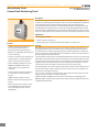
TM
MarinaGuard Series
Ground Fault Monitoring Panel
For Marina Shore Power
Technical Bulletin
NAE1092812 / 04.2013
BENDER Inc. • 700 Fox Chase, Coatesville PA 19320 • Ph: 800-356-4266 / 610-383-9200 • Fax: 610-383-7100
MarinaGuard Series
Ground Fault Monitoring Panel
Ground Fault Monitoring Panel
For Marina Shore Power
Description
MarinaGuard series panels detect ground faults for shore power in marinas. Options are
available for monitoring either main feeders or branch circuits. The MarinaGuard satisfies the
new requirements in the 2011 National Electrical Code, article 555.3, "Ground-Fault
Protection." All models may be set to 100 mA for feeder protection, and may be set lower if
desired. Models for monitoring branch circuits may be steplessly adjustable down to 6 mA.
All models feature a NEMA 4X rated enclosure, with test and reset buttons, power and alarm
LEDs, and a strobe light on the top of the enclosure for clear indication if a fault has occured.
Applications
• Shore power for marinas
MarinaGuard series panel
• Feeder and branch monitoring
• Systems which must satisfy the requirements of NEC 2011, Article 555.3
Features
• Satisfies requirements of NEC article 555.3, "Ground-Fault Protection"
• Ground fault monitoring for marinas
• Options for single feeder monitoring and branch monitoring
• Preset to 100 mA trip level, steplessly ad-
justable down to 10 mA for feeder pro-
tection, 6 mA for branch protection
• TEST and RESET pushbuttons on front
• POWER and TRIPPED LEDs on front
• Strobe light for easily visible alarm indication
• Contact outputs for remote notification or connection to a feeder shunt trip breaker
• NEMA 4X rated, lockable enclosure
• Option for SMS alarm messaging to cell phones
• Multi-channel versions support connec
tion to BENDER communication gate-
ways to standard protocols such as Modbus/TCP
2
Function
MarinaGuard panels detect faults by means of current transformers (CTs). One CT is required per feeder or branch to be monitored (see ordering information). Each feeder /
branch will have all conductors going through the current transformer. For example, in
240/120 V shore power applications, both hot conductors as well as the neutral must be
placed through the current transformer.
If a ground fault is detected, the connected MarinaGuard will activate an alarm. The Fault
Alarm light on the front of the enclosure will illuminate, and the strobe light will activate.
For the branch protection model, a fault on any branch will activate the LED and strobe
light. Once the fault or faults have been cleared, holding the reset button for at least 2
seconds will clear the alarm lights and return the panel to the normal state.
Each model features dry contact outputs, which may be used for remote notification to a
harbor master's office. The dry contacts may also be used to connect to a feeder shunt
trip breaker, if interruption is desired.
The "C" option is available for all model types, which allows for wireless SMS alarm messaging to cell phones when an alarm has activated.
Additionally, MG-S and MG-T branch protection models features compatibility with
BENDER's digital communication system, which may be used to integrate with Ethernet
and Modbus/TCP networks.
MarinaGuard Panel Front (Example shown: MG-1, MG-S, MG-T)
MG-2 and MG-3 versions have one set of ON/ALARM lights and
TEST/RESET buttons per monitor (2 total for MG-2, 3 total for MG3).
3
1 - POWER ON LED / TEST pushbutton: Illuminates when power is applied and no alarms are present. Pushing the button ini
tiates a self-test of the monitor.
2 -ALARM LED / RESET pushbutton: Illuminates when one or
more alarms are detected. Holding the button for at least 2
seconds will reset the device if alarms have been cleared.
3 - Strobe Light: Illuminates when any alarms are detected.
Strobe ON indicates Ground Fault
Ground Fault Monitor
Monitor ON
Push to Test
Ordering Information: Current Transformers
Name
W0-S20
W1-S35
W2-S70
W3-S105
W4-S140
W5-S210
Inside
diameter
Ordering
no.
ø 0.75" (20 mm)
ø 1.4" (35 mm)
ø 2.4" (60 mm)
ø 4.1" (105 mm)
ø 5.5" (140 mm)
ø 8.25" (210 mm)
B 911 787
B 911 731
B 911 732
B 911 733
B 911 734
B 911 735
Fault Alarm
Push to Reset
1
2
Support: 800-356-4266
One current transformer is required per feeder / branch.
Ordering Information: MarinaGuard
Name
Quantity of
feeders / branches
Adjustable
trip level
Number of
contact outputs
Supports COM460IP
Communication Gateway
SMS Alarm
Messaging Support
MG-1
MG-2
MG-3
MG-S
1
2
3
12
10 mA - 10 A
10 mA - 10 A
10 mA - 10 A
6 mA - 20 A
1 individual
2 individual
3 individual
1 common
No
No
No
Yes
No
No
No
No
MG-T
12
6 mA - 20 A
1 common, 12 individual
Yes
No
MG-1C
1
10 mA - 10 A
1 individual
No
Yes
MG-2C
2
10 mA - 10 A
2 individual
No
Yes
MG-3C
3
10 mA - 10 A
3 individual
No
Yes
MG-SC
12
6 mA - 20 A
1 common
Yes
Yes
MG-TC
12
6 mA - 20 A
1 common, 12 individual
Yes
Yes
3
Option "C" - Wireless text messaging of alarms to cell phones
Option C includes a built-in module which allows for SMS messaging to technicians / harbor masters when an alarm is activated. The system
is wireless and uses a SIM card for messaging (SIM card and SMS service sold separately). Alarm notifications and technician phone numbers
are customizable. Multiple phone numbers may be set to simultaneously receive alarm text messages. Most settings are preconfigured at the
factory and very little field adjustments are required. A PLC and connected GSM module are used to control the alarm notification.
All MarinaGuard models support the "C" option.
4
MG-S and MG-T models: Connection to BENDER's communication bus
TCP/IP
Modbus/TCP
Modbus/TCP
SCADA / BMS
Ethernet
Modbus/TCP
COM460IP
BENDER Communication Bus
Strobe ON indicates Ground Fault
Strobe ON indicates Ground Fault
Ground Fault Monitor
Ground Fault Monitor
Monitor ON
Push to Test
Fault Alarm
Push to Reset
Support: 800-356-4266
Monitor ON
Push to Test
Fault Alarm
Push to Reset
Support: 800-356-4266
MG-S and MG-T multi-channel models support connecting to BENDER's advanced communication bus for remote notification of alarms on
shore power. When connecting to the COM460IP communication module, status of MarinaGuard panels may be viewed remotely at a master
station via a standard Ethernet network or Modbus/TCP fieldbus communication. When using an Ethernet network, mobile devices connected wirelessly to the network can view the status of MarinaGuard panels using a special mobile version. BENDER's communication network supports connecting to other BENDER devices as well, including the MK2430 remote indicating station, which manages the status of
multiple connected devices from a single remote.
5
Wiring
• All MarinaGuard models require a 120 VAC supply voltage. Connect L to the designated terminal block, and N to the terminal on the
enclosed ground fault monitor labeled "A2."
• Connect the current transformer(s) per the appropriate schematic below. For models which support more than one current transformer, connect to the appropriate K/L terminal. Use minimum AWG 24, maximum AWG 12 THHN wire.
• All models have contact outputs which may be used for remote notification. Refer to the appropriate schematic below for the normally open or normally closed contact to connect to.
Example Wiring - MG-1
Example Wiring - MG-S
Cust. Connection
120 VAC Aux Supply
Cust. Connection
120 VAC Aux Supply
N
L
N
L
Cust. Connection
GROUND
Cust. Connection
GROUND
l - Row
Current
Transformer
120 VAC N/O
For External Alarm
1/2
5/6
3/4
120 VAC N/O
For External Alarm
1 2 3 4 5 6 7 8 9 10 11 12
To External 120VAC N/O
Alarm, Contactor,
Shunt Trip, Etc.
External Current
Transformer(s)
Monitoring Feeder(s) /
Branch(es)
Repeat For All Channels
123 4
123 4
6
k- Row
Current Transformer
L N
L N
External Current
Transformer
Monitoring Feeder /
Branch
9/10
11/12
7/8
To External 120VAC N/O
Alarm, Contactor,
Shunt Trip, Etc.
Wiring - Current Transformer Placement in a Typical Shore Power Application
Each monitored feeder or branch requires one current transformer. The current transformer must be large enough to have all conductors passing through it. Position 1 (before the primary MCB) and position 2 (between the primary MCB and branch CBs) are recommended placements for feeder monitoring, and typically used with MG-1, MG-2, and MG-3 MarinaGuard models. Position 3 (individual
branches) is for branch monitoring, and is recommended with MG-S and MG-T series MarinaGuard panels.
240/120V Grounded Neutral
Supply Transformer
Current
Transformer (CT)
Position 1
Primary Main Circuit Breaker
Current
Transformer (CT)
Position 2
Power Distribution
Main Circuit Breaker
Branch Circuit Breakers
Strobe ON indicates Ground Fault
Ground Fault Monitor
Monitor ON
Push to Test
Fault Alarm
Push to Reset
Support: 800-356-4266
Current
Transformer (CT)
Position 3
Shore Power Pedestal
Receptacle Circuit Breaker
Receptacle
7
Post-Installation Adjustments
In most applications, changing settings on enclosed ground fault monitors is not necessary. However, should changes be required, refer
to the respective devices below.
MG-1, MG-2, and MG-3 Series MarinaGuard Panels
Settings for MG-1, MG-2, and MG-3 panels are changed on the enclosed ground fault monitor with DIP switches and potentiometers.
2
3
4
7 8
9
}
1
10
A
B
C
D
E
F
5
6
1 -Combined TEST and RESET button: short depress (< 1s) =
RESET; long depress (> 2s) = TEST
2 -Power On LED
3 -Alarm LED: Illuminates when the response value has been exceeded. Flashes when the CT connection alarm is active.
4 -LED bar graph indicator: shows the measuring value in percent of the preset response value.
5 -Potentiometer for setting the response delay (0…1 s).
6 -Potentiometer for setting the response value (x 1…10 mA)
DIP switch settings (white = switch position)
7 - Alarm relay operation settings
A - Normally de energized B -Normally energized
8 - Fault memory / latching behavior settings
A - Fault memory ON (latching mode)
B - Fault memory OFF (non-latching mode)
9 -Sample response value settings
A - 10 mA
B - 30 mA
C - 100 mA
x 1…10
D - 300 mA
E - 500 mA
F - 1000 mA
10 -Time delay settings
A - x 1
0…1 s
B - x 10
}
}
MG-S and MG-T Series MarinaGuard Panels
MG-S and MG-T series panels utilize a digital display with built-in menu to make settings changes. Refer to MarinaGuard User Manual
(NAE1095810) for information on changing available settings.
8
How Does a MarinaGuard Detect Ground Faults?
In a typical shore power application, the secondary of the shore power transformer provides grounded 240/120 VAC power. When monitoring the feeder, the MarinaGuard will be connected to a current transformer. The current transformer will be placed around both
hot conductors and the neutral (the ground conductor is not placed through). The MarinaGuard will detect faults downstream of the
current transformer, including any leakage current between the transformer and wiring to the pedestals, or to a connected boat.
Ground faults are detected by looking for a net imbalance of current between the phases - this correleates to an equivalent amount of
leakage current downstream.
Branch monitoring works in a similar manner, however each individual branch leading to the pedestals is monitored seperately.
Notification can be provided as to the particular branch that has the ground fault.
Shore power supply
MarinaGuard
Pedestal
Ground
Possible ground fault paths in a shore power application
Locating Ground Faults - MG-S / MG-T Series MarinaGuard Panels
If an MG-S or MG-T series MarinaGuard is being used for branch detection, fault location will be done automatically. The display of the
enclosed ground fault monitor will indicate which branch has the fault. The screen will also display how much leakage current was detected.
MG-T models additionally feature individual contact outputs for each branch, which may be used for remote notification or branch interruption via a device such as a shunt trip breaker.
ALARM
1/1
Residual current
130 mA
Addr.: 2 Chan.: 12
(
Digital display of MG-S /MG-T ground fault monitor displaying a ground fault on branch 12
Locating Ground Faults - MG-1, MG-2, and MG-3 Series MarinaGuard Panels
If an MG-1, MG-2, or MG-3 is being used for feeder protection, several options are available for locating faults:
• Shutting off individual branch breakers until pressing the RESET button on the front of the panel resets the system back to the
normal condition
• Using a low-mA, clamp-on ammeter to clamp around individual shore cords. A clamp-on ammeter must have all conductors going through the clamp-on current transformer.
9
Enclosure Dimensions (All Models)
Dimensions listed in inches
12.750
10.250
F
.150 TOP
.140 TOP
R.375
6.375
5.125
2.563
.590
2.563
.885
2.813
13.405
5.0 °
.150
60.0 °
5.828
4.125
6.480
2.063
.500
10.750
6.140
2.063
.800 TOP
.425 TOP
.438
F
.566
SEE DETAIL A
Document NAE1092812 / 04.2013 / © Bender Inc.
5.125
TM
USA • Coatesville, PA
Toll-Free: 800-356-4266 • Main: 610-383-9200
Fax: 610-383-7100 • E-mail: [email protected]
Canada • Mississauga, ON
Toll-Free: 800-243-2438 • Main: 905-602-9990
Fax: 905-602-9960 • E-mail: [email protected]
bender.org • bender.org/mobile