Download User Manual
Transcript
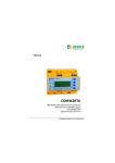
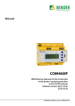
Manual COM461MT BMS-Ethernet gateway for the connection of Bender devices with BMS support to Ethernet (TCP/IP) using the Modbus/TCP protocol Software version: D402 V1.0x COM461MT_D00011_00_M_XXEN/05.2013 Bender GmbH & Co. KG Londorfer Str. 65 • 35305 Grünberg • Germany Postfach 1161 • 35301 Grünberg • Germany Tel.: +49 6401 807-0 Fax: +49 6401 807-259 E-Mail: [email protected] Web: http://www.bender-de.com © Bender GmbH & Co. KG All rights reserved. Reprinting only with permission of the publisher. Subject to change! Table of Contents 1. Making effective use of this document ....................................................... 7 1.1 1.2 1.3 How to use this manual ................................................................................. 7 Overview of chapters ...................................................................................... 7 Quick reference guide .................................................................................... 8 2. Safety instructions ........................................................................................... 9 2.1 2.2 2.3 2.4 Work activities on electrical installations ................................................ 9 Intended use ...................................................................................................... 9 Address setting and termination ............................................................. 10 Protection against unauthorized access .............................................. 10 3. Product description ....................................................................................... 11 3.1 3.2 3.3 3.4 Scope of supply .............................................................................................. 11 A short description ....................................................................................... 11 Properties ......................................................................................................... 11 Possible applications ................................................................................... 12 4. Installation, connection and commissioning ........................................... 13 4.1 4.2 4.3 4.4 4.5 4.5.1 Preliminary considerations ........................................................................ COM461MT on the internal BMS bus ..................................................... Installing the device ..................................................................................... Connecting the device ................................................................................ Commissioning .............................................................................................. Determining address data ......................................................................... 13 14 16 17 19 22 5. The BMS-Ethernet gateway COM461MT ................................................... 23 5.1 Display and operating elements ............................................................. 23 6. Data access using Modbus/TCP protocol .................................................. 25 6.1 Exception code ............................................................................................... 25 COM461MT_D00011_00_M_XXEN/05.2013 3 Table of Contents 6.2 6.3 6.4 6.5 Modbus requests ........................................................................................... 26 Modbus responses ........................................................................................ 26 Structure of the exception code .............................................................. 27 Modbus address structure for BMS devices ......................................... 27 7. Modbus process image in the memory of the COM461MT ................... 29 7.1 Requesting data ............................................................................................. 29 7.1.1 Modbus function code ................................................................................ 29 7.1.2 How are the memory areas organised? ................................................ 29 7.2 Memory scheme of the process image ................................................. 30 7.2.1 BMS device address assignment on the Modbus .............................. 30 7.2.2 Memory scheme of an individual BMS device .................................... 31 7.2.3 Device name ................................................................................................... 33 7.2.4 Timestamp ....................................................................................................... 34 7.2.5 C = Common alarm and D = Device lost (device failure) ................ 34 7.2.6 Channels 1 to 32 With analogue and/or digital values .................... 35 7.2.6.1 Float = Floating point value of the BMS channels .................... 35 7.2.6.2 A&T = Alarm type and test type (internal/external) ................. 36 7.2.6.3 R&U = Range and unit ......................................................................... 37 7.2.6.4 Channel description ............................................................................. 39 7.2.6.5 Channel 33 to 64 ................................................................................... 40 7.3 Reference data records of the process image ..................................... 41 7.3.1 Address assignment of the reference data record ............................ 41 7.3.2 Reference value on channel 1 ................................................................... 42 7.3.3 Reference value on channel 2 ................................................................... 43 7.3.4 Explanation of how to access floating point values ......................... 43 7.4 Channel descriptions for the process image ....................................... 45 7.5 Modbus control commands ...................................................................... 57 8. Technical data ................................................................................................ 59 8.1 8.2 8.3 4 Tabular data .................................................................................................... 59 Dimension diagram ...................................................................................... 61 Standards, approvals, certifications ........................................................ 61 COM461MT_D00011_00_M_XXEN/05.2013 Table of Contents 8.4 Ordering data ................................................................................................. 62 9. Troubleshooting ............................................................................................ 63 9.1 9.2 9.2.1 9.2.2 Damage in transit .......................................................................................... Malfunctions ................................................................................................... What should be checked? .......................................................................... Where do you go to get help? .................................................................. 63 63 63 64 INDEX ..................................................................................................................... 65 COM461MT_D00011_00_M_XXEN/05.2013 5 1. Making effective use of this document 1.1 How to use this manual This operating manual is aimed at qualified experts in electrical engineering and communications technology! To make it easier for you to understand and revisit certain sections of text and instructions in the manual, we have used symbols to identify important instructions and information. The meaning of these symbols is explained below: Information calling attention to hazards are marked with this warning symbol. Information intended to assist the user to make optimum use of the product are marked with the Info symbol. 1.2 Overview of chapters Making effective use of this document: This chapter gives you instructions on how to use this documentation Safety instructions: This chapter describes the dangers during installation and when operating the device Product description: This chapter describes the scope of delivery and features of the product COM461MT_D00011_00_M_XXEN/05.2013 7 Making effective use of this document Installation, connection and commissioning: This chapter shows the steps to take up to commissioning The BMS-Ethernet gateway COM461MT: This chapter describes the display and operating elements Data access using Modbus/TCP protocol: Describes how to send requests to the Modbus/TCP server in the COM461MT and how the responses are to be interpreted Modbus process image in the COM461MT's memory: In this chapter, the representation of BMS data on Modbus/TCP structures is described in detail Technical data: In addition to the technical data you will find here ordering data Troubleshooting: This chapter offers service and support in case of malfunction. In addition you will also find here information on our Technical Service department Index: The key word index assists you in finding the term you are searching for. 1.3 Quick reference guide Connection of the COM461MT If you are familiar with the installation and connection of electrical devices as well as networking, particularly with Ethernet, you can start right away with the wiring diagram on page 17. It may also be helpful to refer to block diagrams representing an application example with an internal bus on page 14. Using the Modbus/TCP functions Information about this complex field can be found from page 25. 8 COM461MT_D00011_00_M_XXEN/05.2013 2. Safety instructions 2.1 Work activities on electrical installations Only skilled persons are permitted to carry out the work necessary to install, commission and run a device or system. Compliance with applicable regulations governing work on electrical installations, and with the regulations derived from and associated with them, is mandatory. EN 50110 is of particular importance in this regard. Any work on electrical installations which is not carried out properly can lead to death and injury! If the device is being used in a location outside the Federal Republic of Germany, the applicable local standards and regulations must be complied with. European standard EN 50110 can be used as a guide. 2.2 Intended use The BMS-Ethernet gateway COM461MT connects the serial BMS bus to Ethernet TCP/IP networks. The gateway converts alarms, measured values and statuses from the BMS bus to the Modbus/TCP protocol. This allows connection to Modbus networks. The gateway is operated on the internal BMS bus. COM461MT_D00011_00_M_XXEN/05.2013 9 Safety instructions 2.3 Address setting and termination In order to ensure proper functioning of the BMS-Ethernet gateway COM461MT, correct address assignment and termination of the BMS bus is of utmost importance. Assigning addresses that are already used by existing devices in the BMS or TCP/IP networks concerned may cause serious malfunctions. Ensure correct address setting and termination of the COM461MT. For details refer to the chapter basic configuration from page 19. 2.4 Protection against unauthorized access Risk of damage to equipment due to unauthorized access. Attackers from the Internet may be able to read data and to change settings. It is absolutely necessary to ensure that - the network is separated from the Internet - common security mechanisms are applied (firewall, VPN access) 10 COM461MT_D00011_00_M_XXEN/05.2013 3. Product description 3.1 Scope of supply You will receive: the COM461MT an operating manual 3.2 A short description The BMS-Ethernet gateway COM461MT contains a Modbus/TCP server that converts the BMS data for a Modbus client. A web server makes it possible to configure the COM461MT (see “Commissioning” on page 19). Ethernet-TCP/IP interface: The coupling is performed via the internal Layer-2 switch. Two Ethernet ports are available. Interface on the BMS side: COM461MT can be operated as a master or slave. 3.3 Properties Setting of the IP address, BMS address and time/date using standard web browser Time synchronisation for all BMS bus devices Integrated Ethernet switch: 2 x RJ45, 10/100 Mbit/s Operation on the internal BMS bus Modbus/TCP data access to the internal BMS bus, max. 150 BMS devices Commands can be sent from an external application (e.g. data display software) to BMS devices and measured values read. COM461MT_D00011_00_M_XXEN/05.2013 11 Product description 3.4 Possible applications 12 Usage of professional data display programs by converting the BMS data to the Modbus/TCP protocol Observing and analysing Bender products that support communication, such as RCMS, EDS and MEDICS® systems COM461MT_D00011_00_M_XXEN/05.2013 4. Installation, connection and commissioning The BMS-Ethernet gateway is normally integrated into existing LAN structures, but can also be operated via a single PC on the Ethernet side. If you are familiar with the configuration of computer networks, you can carry out the connection of the COM461MT yourself. Otherwise please contact your EDP administrator! 4.1 Preliminary considerations 1. Have all the questions as regards the installation been answered by the technician responsible for the installation? 2. The device is operated on the internal BMS bus. Is the BMS address to be set known? If, apart from the COM461MT, an alarm indicator and test combination MK800 is connected to the internal bus, the COM461MT must not have the address 1 (master). You will find more detailed information on the BMS topic, in particular about the wiring of bus devices, in the separate document "BMS bus". You can download the document from the download area of the website www.bender-de.com. 3. Request network data from the technician responsible for the installation. The IP address and subnet mask are to be set manually. 4. Ask for the IP address of the NTP server, which is required for automatic time setting. 5. Are suitable PC hardware and software available for commissioning? Minimum system requirements: 1.6-GHz processor/512 MB RAM / Windows XP/Vista/7/Web browser. For initial connection, the basic configuration of the COM461MT is to be undertaken outside the installation, depending on the specific situation. COM461MT_D00011_00_M_XXEN/05.2013 13 Installation, connection and commissioning 4.2 COM461MT on the internal BMS bus Bender systems such as EDS46x/49x, RCMS46x/49x and MEDICS communicate with each other via the Bender measuring device interface BMS. The BMS-Ethernet gateway COM461MT provides the coupling between the BMS bus and TCP/IP networks. The internal Modbus/TCP server in the COM461MT communicates with the Modbus/TCP client via these networks. The following block diagram illustrates the operation of the gateway on the internal BMS bus. Internal and external BMS bus The majority of Bender devices communicate via the internal BMS bus. Individual devices, such as MK800, TM 800 or Bender panels can communicate via both the internal BMS bus (BMS i) and the external BMS bus (BMS e). The BMS-Ethernet gateway COM461MT can only communicate via the internal BMS bus (BMS i). 14 COM461MT_D00011_00_M_XXEN/05.2013 Installation, connection and commissioning COM461MT Fig. 4.1: Block diagram of a coupling between an internal BMS bus and TCP/IP networks COM461MT_D00011_00_M_XXEN/05.2013 15 Installation, connection and commissioning 4.3 Installing the device Possible methods of mounting: DIN rail mounting Screw mounting with 2 x M4 (dimension diagram on page 61) When installing the device, please take into consideration that the device is only to be used in locations that are protected from unauthorised entry! This can be installation in a switch cabinet, for example. 16 COM461MT_D00011_00_M_XXEN/05.2013 Installation, connection and commissioning 4.4 Connecting the device For UL applications, the following is to be observed: – Supply voltage Us see nameplate and ordering data – Maximum ambient temperature 55°C – For use in pollution degree 2 environments – Only 60/75 °C copper wires are to be used – Tightening torque for terminals 0.5…0.6 Nm Connect the terminals and sockets on the COM461MT according to the wiring diagram. US 6A 6A A1 A2 A1 A2 ETH1 ETH2 2 x RJ45 COM461MT_D00011_00_M_XXEN/05.2013 A B BMS-Bus RS-485 17 Installation, connection and commissioning Terminal Description A1, A2 Connection to the supply voltage, 6 A fuse recommended, two-pole fuses should be used on IT systems. For UL and CSA applications, it is mandatory to use 5 A fuses ETH1, ETH2 Two connections for connection to a personal computer or to the local network (hub, switch, router); Connection using a CAT5 cable; internal Layer-2 switch with cable autodetect. A, B Connection to the internal BMS bus with shielded cable (e.g. J-Y(St)Y 2x0.8) Ron/off (A,B) Switch for BMS bus termination. When the device is installed at the end of the bus, set the terminating switch to "on". 18 COM461MT_D00011_00_M_XXEN/05.2013 Installation, connection and commissioning 4.5 Commissioning 1. Apply the supply voltage to the COM461MT. The green "ON" LED illuminates. 2. Connect the COM461MT to a PC and open a web browser. 3. Enter the IP address for the COM461MT (factory setting 192.168.0.254). The page for the device settings appears: COM461MT_D00011_00_M_XXEN/05.2013 19 Installation, connection and commissioning Without address data it is not possible to access the device. If the IP address and subnet mask are not known, this information can only be found with a large amount of effort (see “Determining address data” on page 22). If the factory settings are changed, always note the modified address data in the following table. 4. Make the necessary settings. Make a note of the modified settings: Parameter IP address Factory setting Meaning IP address of the COM461MT 192.168.0.254 Subnet Subnet mask of the COM461MT 255.255.0.0 Bms address Address on the internal BMS bus 2 Modbus control Enable or disable control via Modbus On NtpServer address IP address of the NTP server, is required for automatically setting the time 192.168.0.123 Time zones setting (12…+13): UTC + 1 h = CET UTC + 2 h = … UTC + 3 h = … +1 UTC 20 Modified setting COM461MT_D00011_00_M_XXEN/05.2013 Installation, connection and commissioning Parameter Summertime Date Time skip time Meaning Select summer time setting: Off = Function disabled DST = Automatic switchover, USA, CDN CEST = Automat. switchover, Central Europe On = Set time zone + 1 h Factory setting Modified setting Off Date Time of day Skip time setting. The time remains unchanged. 5. Click "Change" to save the modified settings. Or click "Undo" to undo the changes made. COM461MT_D00011_00_M_XXEN/05.2013 21 Installation, connection and commissioning 4.5.1 Determining address data The IP address and subnet mask set must be known for the operation of the COM461MT. If these data have been changed without making a note of the modified address data, the following options are available: Enter NetBIOS name in the web browser: "http://com461mt" or "com461mt" (dependent on the browser). Requirement: COM461MT and PC must lie in the same address range. Connect a COM460IP with option C to the network. Set address data again using COM460IP. Connect a COM460IP with option A to the network. Read address data using COM460IP. Install an IP scanner on a PC in the network and find address. Have COM461MT reset to the factory setting by Bender. 22 COM461MT_D00011_00_M_XXEN/05.2013 5. The BMS-Ethernet gateway COM461MT 5.1 Display and operating elements COM461 COMTRAXX® 1 2 Fig. 5.1: COM461MT front panel Key 1 "ON" LED lights when supply voltage is applied 2 Ron/off (beside terminals A, B) Switch for terminating the BMS bus. When the device is installed at the end of the bus, set the terminating switch to "on". COM461MT_D00011_00_M_XXEN/05.2013 23 The BMS-Ethernet gateway COM461MT 24 COM461MT_D00011_00_M_XXEN/05.2013 6. Data access using Modbus/TCP protocol Requests are sent to the Modbus/TCP server in the COM461MT using function code FC4 (read input register). The server generates a function-related response and sends it to the Modbus client. 6.1 Exception code If a request cannot be answered for whatever reason, the server sends a socalled exception code with which possible faults can be narrowed down. Exception code Description 0x01 Impermissible function 0x02 Impermissible data access 0x03 Impermissible data value 0x04 Slave device error 0x05 Acknowledgement of receipt (response delayed) 0x06 Request not accepted (repeat request, if necessary) 0x08 Memory: parity error 0x0A Gateway path not available 0x0B Gateway error COM461MT_D00011_00_M_XXEN/05.2013 25 Data access using Modbus/TCP protocol 6.2 Modbus requests The required words of the process image can be read from the input registers in the COM461MT using the function code FC4. For this purpose, the start address and the number of registers to be read need to be entered. Example: The words 0 and 1 are to be read from the input registers 0x100 and 0x101. Byte Name Example Byte 0, 1 Transaction identifier 0x0000 Byte 2, 3 Protocol identifier 0x0000 Byte 4, 5 Length field 0x0006 Byte 6 Unit identifier 0x01 Byte 7 MODBUS function code 0x04 Byte 8, 9 Device address (BMS int * 0x100) 0x0100 (corresponds to the internal BMS address 1), internal BMS bus address assignment Byte 10, 11 Number of words 0x0002 6.3 Modbus responses The responses consist of 2 bytes per register. The MSB is the first byte. Byte Name Example … … … Byte 7 MODBUS function code 0x04 Byte 8 Byte count 0x04 26 COM461MT_D00011_00_M_XXEN/05.2013 Data access using Modbus/TCP protocol Byte Name Example Byte 9, 10 Value register 0 0x1234 (fictitious value) Byte 11, 12 Value register 1 0x2345 (fictitious value) 6.4 Structure of the exception code Byte Name Example … … … Byte 7 MODBUS function code 0x84 Byte 8 Exception code 0x01 or 0x02 6.5 Modbus address structure for BMS devices Address range Number of bytes Number of words Device name 0x00…0x09 20 bytes 10 words Timestamp 0x0A…0x0D 8 bytes 4 words Common alarm 0x0E (high byte) 1 byte 0.5 words No BMS bus connection 0x0E (low byte) 1 byte 0.5 words Function Not used 0x0F 2 bytes 1 word Channel 1…32 0x10…0x8F 32 x 8 bytes 128 words Alarm and test Channel 33…64 0x90…0xFC 218 x 8 bytes 109 words COM461MT_D00011_00_M_XXEN/05.2013 27 Data access using Modbus/TCP protocol 28 COM461MT_D00011_00_M_XXEN/05.2013 7. Modbus process image in the memory of the COM461MT The device holds a process image in the memory. This image represents the current statuses and values of up to 150 BMS devices for each monitored internal BMS bus. 7.1 Requesting data 7.1.1 Modbus function code The memory in the COM461MT can be read using the Modbus function 4 "Read input registers". The volume of the data requested depends on the number of bytes selected in the Modbus client used. Up to 125 words (0x7D) can be read with a single request. An individual addressable byte, such as the set bit for a stored common alarm, can also be read. 7.1.2 How are the memory areas organised? Start address End of memory area Size of memory area Reference values for test purposes 0x0000 0x00FF 0x0100 Process image 0x0100 0x95FF 0x9500 Not used 0x96FF 0xFFFF 0x6900 Memory utilisation For some Modbus clients an offset of 1 must be added to the register addresses. Example: process image start address = 0x0101. COM461MT_D00011_00_M_XXEN/05.2013 29 Modbus process image in the memory of the COM461MT The assignment of the memory addresses and the associated memory content is described below. 7.2 Memory scheme of the process image 7.2.1 BMS device address assignment on the Modbus As illustrated in the table, the Modbus start address for the respective process image is derived from the BMS device address. 256 (0x100) words or 512 bytes are reserved for each BMS device. They contain all the information requested and transmitted from the BMS bus. Modbus address ranges of the process images in the memory Word BMS device address HiByte LoByte 00 … 1 0x01 Device 1 2 0x02 Device 2 3 0x03 … … … 32 0x20 Device 32 … … … 150 0x96 Device 150 FF Device 3 Tab. 7.1: Modbus start address for each BMS device for which a request can be sent. 30 COM461MT_D00011_00_M_XXEN/05.2013 Modbus process image in the memory of the COM461MT 7.2.2 Memory scheme of an individual BMS device BMS devices can feature various types of analogue and/or digital channels. Please take into consideration that there are device-specific differences: BMS devices usually feature 12 channels MK800/TM800 supports up to 64 digital channels in the master mode The channels 33 to 64 transmit digital messages only Use the tables on page 30 and page 33 to determine the start address to request the following device parameters: Device name Timestamp Common alarm Device error BMS channel Example: In our example, data is to be requested from channel 2 of the device with BMS address 3. How is the start address determined to send the request for the channel? In our example, the relevant cells in the table are marked bold. 1. For BMS device address 3 the first part of the address, 0x03 (high byte), is taken from Table 7.1. 2. For channel 2 the second part of the address, 0x14 (low byte), is taken from Table 7.2. For the number of words to be requested the number 4 is taken from the same table: (0x14 to 0x17 = 0x04). 3. The start address 0x0314 is formed from the high byte and low byte. COM461MT_D00011_00_M_XXEN/05.2013 31 Modbus process image in the memory of the COM461MT 0xC0 0xB0 0xA0 0x90 0x80 0x70 0x60 0x50 0x40 0x30 0x20 0x10 0x00 LoByte 33 34 35 36 37 38 39 40 41 42 43 44 45 46 47 48 49 50 51 52 53 54 55 56 57 58 59 60 61 62 63 64 Memory image of a BMS device 0 1 2 3 4 5 6 7 8 9 A B C D E F ------------------------- Device type ------------------------- ---- Timestamp ---- C D R. Channel 1 Channel 2 Channel 3 Channel 4 Channel 5 Channel 6 Channel 7 Channel 8 Channel 9 Channel 10 Channel 11 Channel 12 Channel 13 Channel 14 Channel 15 Channel 16 Channel 17 Channel 18 Channel 19 Channel 20 Channel 21 Channel 22 Channel 23 Channel 24 Channel 25 Channel 26 Channel 27 Channel 28 Channel 29 Channel 30 Channel 31 Channel 32 R. R. R. R. R. R. R. R. R. R. R. R. R. R. R. R. R. R. R. R. R. R. R. R. R. R. R. R. R. R. R. R. R. R. R. R. R. R. R. R. R. R. R. R. R. R. R. R. R. R. R. R. R. R. R. R. R. R. R. R. R. R. R. R. R. R. R. R. R. R. R. R. R. R. R. R. R. R. R. R. R. R. R. R. R. R. R. R. R. R. R. R. R. R. R. R. 32 COM461MT_D00011_00_M_XXEN/05.2013 0xE0 0xD0 R. R. R. R. R. R. R. R. R. R. R. R. R. R. R. R. R. R. R. R. R. R. R. R. R. R. R. R. R. R. R. R. 0xF0 Modbus process image in the memory of the COM461MT R. R. R. R. R. R. R. R. R. R. R. R. R. R. R. R. R. R. R. R. R. R. R. R. R. R. R. R. R. R. R. R. R. R. R. R. R. R. R. R. R. R. R. R. R. R. R. R. R. R. R. R. R. R. R. R. R. R. R. R. R. R. R. R. Tab. 7.2: Modbus address assignment of the channels in a BMS device; Hex representation: horizontal = units , vertical = sixteens Abbreviations for memory contents: C = Common alarm D = Device lost (device failure) R. = Reserved A detailed description of the data formats for the device name, timestamp etc. is given below. 7.2.3 Word 0x00 Device name 0x01 0x02 0x03 0x04 0x05 0x06 0x07 0x08 0x09 ASCII text, 10 words/20 bytes The device name is set using a BMS bus scan. COM461MT_D00011_00_M_XXEN/05.2013 33 Modbus process image in the memory of the COM461MT 7.2.4 Timestamp Word 0x0A HiByte LoByte Year YY 0x0B 0x0C HiByte LoByte HiByte Month MM Day DD Hour hh LoByte 0x0D HiByte LoByte Minute Second mm ss Reserved The timestamp is set according to a datagram received from a transmitting device. 7.2.5 C = Common alarm and D = Device lost (device failure) Word 0x0E HiByte LoByte C D Common alarm, 1 byte: LSB = 0 or 1 Device error, 1 byte: LSB = 0 or 1 The common alarm bit is set as soon as an alarm status from the respective BMS device is detected. The device error bit is set when communication with the respective BMS device is no longer possible. 34 COM461MT_D00011_00_M_XXEN/05.2013 Modbus process image in the memory of the COM461MT 7.2.6 Channels 1 to 32 With analogue and/or digital values Word 0x00 HiByte LoByte 0x01 HiByte 0x02 LoByte Floating point value (Float) 0x03 HiByte LoByte AT&T R&U HiByte LoByte Channel description Every analogue BMS device channel can contain alarm messages, operating messages, measured values, test messages and descriptive text. Both analogue and digital information can be transmitted. AT&T = Alarm type and test type (internal/external) R&U = Range and unit For details on the channel description refer to chapter 7.4. Float = Floating point value of the BMS channels HiByte LoByte 8 7 LoByte 16 15 HiByte 0x01 0 0x00 24 23 22 Bit Byte Word 31 30 7.2.6.1 S E E E E E E E E MMMMMMMMMMMMMMMMMMMMMMM Representation of the bit order for processing analogue measured values according to IEEE 754 S = Sign E = Exponent M = Mantissa COM461MT_D00011_00_M_XXEN/05.2013 35 Modbus process image in the memory of the COM461MT 2 1 0 Meaning Error 3 Alarm 4 Reserved 5 Reserved 6 Status 7 Test internal Test Alarm type Bit A&T = Alarm type and test type (internal/external) Test external 7.2.6.2 X X X X X 0 0 0 No alarm X X X X X 0 0 1 Prewarning 0 0 X X X 0 1 0 Device error X X X X X 0 1 1 Reserved X X X X X 1 0 0 Alarm (yellow LED), e.g. insulation fault X X X X X 1 0 1 Alarm (red LED) X X X X X 1 1 0 Reserved X X X X X … … … Reserved X X X X X 1 1 1 Reserved 0 0 X X X X X X No test 0 1 X X X X X X Internal test 1 0 X X X X X X External test The alarm type is coded by the bits 0 to 2. The bits 3 and 4 are reserved and always have the value 0. Bit 5 usually has the value 0 and represents the digital value of the status. This column is relevant for the SMI472 only. Bit 6 or 7 are usually set when an internal or external test has been completed. Other values are reserved. The complete byte is calculated from the sum of the alarm type and the test type. 36 COM461MT_D00011_00_M_XXEN/05.2013 Modbus process image in the memory of the COM461MT 7.2.6.3 Unit Bit R&U = Range and unit 7 6 5 4 3 2 1 0 Meaning X X X 0 0 0 0 0 Invalid (init) X X X 0 0 0 0 1 No unit X X X 0 0 0 1 0 Ω X X X 0 0 0 1 1 A X X X 0 0 1 0 0 V X X X 0 0 1 0 1 % X X X 0 0 1 1 0 Hz X X X 0 0 1 1 1 Baud X X X 0 1 0 0 0 F X X X 0 1 0 0 1 H X X X 0 1 0 1 0 °C X X X 0 1 0 1 1 °F X X X 0 1 1 0 0 Second X X X 0 1 1 0 1 Minute X X X 0 1 1 1 0 Hour X X X 0 1 1 1 1 Day X X X 1 0 0 0 0 Month X X X … … … … … X X X 1 1 1 1 0 CODE X X X 1 1 1 1 1 Reserved X X X … … … … … Reserved X X X Reserved 1 1 1 1 COM461MT_D00011_00_M_XXEN/05.2013 1 Reserved 37 Modbus process image in the memory of the COM461MT Range of validity Bit 7 6 5 4 3 2 1 0 Meaning 0 0 X X X X X X True value 0 1 X X X X X X True value is smaller 1 0 X X X X X X True value is larger 1 1 X X X X X X Invalid value The unit is coded in the bits 0 to 4. The bits 6 and 7 describe the range of validity of a value. Bit 5 is reserved. The whole byte is calculated from the sum of the unit and the range of validity. Caution! If the unit byte refers to CODE, the recorded value or status will result in a text message. The content of this text message is listed in the table on page 39 or page 45. The floating point value contains an internal CODE but no valid measured value. 38 COM461MT_D00011_00_M_XXEN/05.2013 Bit Alarms and warnings 0 0 0 0 0 0 0 0 0 0 0 0 0 COM461MT_D00011_00_M_XXEN/05.2013 0 0 0 0 0 0 0 0 0 0 0 0 0 0 0 0 0 0 0 0 0 0 0 0 0 0 0 0 0 0 0 0 0 0 0 0 0 0 0 0 0 0 0 1 1 1 1 1 0 0 0 0 0 0 1 0 0 0 0 1 1 1 1 0 0 0 0 0 1 1 0 0 1 1 0 0 1 1 0 0 1 1 0 1 0 1 0 1 0 1 0 1 0 0 10 9 8 7 6 5 4 3 2 1 0 Vacuum Oxygen Failure distribution board Reserved Insulation OP light Failure line 2 Failure line 1 Overtemperature Overload Insulation fault Reserved Meaning … Compressed air 5 bar 0 0 0 0 0 0 0 0 0 0 0 0 0 2 … 0 0 0 0 0 0 0 0 0 0 0 0 0 3 12 0 0 0 0 0 0 0 0 0 0 0 0 0 4 0 0 0 0 0 0 0 0 0 0 0 0 0 0 5 … … … … … … … … … … … … … … … … 0 0 0 0 0 0 0 0 0 0 0 0 6 decimal Anaesthetic gas 0 0 0 0 0 0 0 0 0 0 0 7 LoByte 11 0 0 0 0 0 0 0 0 0 0 0 0 0 0 0 0 0 0 0 0 0 0 0 0 0 0 0 8 15 14 13 12 11 10 9 HiByte 0x03 7.2.6.4 Byte Word Modbus process image in the memory of the COM461MT Channel description A code with the associated descriptive text is available for each channel. The table above only shows an extract from the texts. For a complete list of the available codes or texts refer to page 45. 39 Modbus process image in the memory of the COM461MT 7.2.6.5 1 0 Meaning Error 2 Alarm 3 Reserved 4 Reserved 5 Status 6 Test internal 7 Test external Test Alarm type Bit Channel 33 to 64 X X X X X 0 0 0 No alarm X X X X X 0 0 1 Prewarning 0 0 0 X X 0 1 0 Device error X X X X X 0 1 1 Reserved X X X X X 1 0 0 Alarm (yellow LED), e.g. insulation fault X X X X X 1 0 1 Alarm (red LED) X X X X X 1 1 0 Reserved X X X X X … … … Reserved X X X X X 1 1 1 Reserved 0 0 X X X X X X No test 0 1 X X X X X X Internal test 1 0 X X X X X X External test The BMS channels 33 to 64 only provide digital information. The information is coded as an alarm or message type or test type (internal, external). The coding is similar to the data format AT&T for the channels 1 to 32, with the exception of the additional bit 4, which is used for coding device errors, e.g. connection faults or internal device errors. 40 COM461MT_D00011_00_M_XXEN/05.2013 Modbus process image in the memory of the COM461MT 7.3 Reference data records of the process image To make it easier to check the configuration and the Modbus/TCP data access to BMS devices, COM461MT provides a reference data record at the virtual BMS address 0. A real BMS device cannot have BMS address 0! Address 0 only serves to simulate data access. Special features of the Modbus communication are the byte offset and the word and byte order in the memory (Big Endian). At the end of this chapter, a few examples of correct configuration are given, which might be helpful. 7.3.1 Address assignment of the reference data record As shown in the following table, the Modbus start address for access to the reference data record is derived from BMS device address 0. Modbus addresses for reference data record LoByte Virtual BMS device address Word 0 HiByte 0x00 00 0E 10 14 Device type Common alarm Channel 1 Channel 2 Tab. 7.3: Start addresses for the reference data record request COM461MT_D00011_00_M_XXEN/05.2013 41 Modbus process image in the memory of the COM461MT The start addresses provide the following reference values: 0x0000: TEST (device type) 0x000E: 1 (common alarm, LSB of the high byte is set) 0x0010: 230 V undervoltage (reference value on channel 1) 0x0014: 12.34 A overcurrent (reference value on channel 2) 7.3.2 Reference value on channel 1 The following reference value is stored in this channel: 230.0 V undervoltage Word 0x10 0x11 0x12 0x13 HiByte LoByte HiByte LoByte HiByte LoByte HiByte LoByte 0x43 0x66 0x00 0x00 0x00 0x04 0x00 0x4D Floating point value (Float) AT&T R&U Description 230.0 No/No Volt Undervoltage Tab. 7.4: Reference data stored in channel 1 42 COM461MT_D00011_00_M_XXEN/05.2013 Modbus process image in the memory of the COM461MT 7.3.3 Reference value on channel 2 The following reference value is stored in this channel: 12.34 A Word 0x14 0x15 0x16 0x17 HiByte LoByte HiByte LoByte HiByte LoByte HiByte LoByte 0x41 0x45 0x70 0xA4 0x00 0x03 0x00 0x4A AT&T R&U Floating point value (Float) 12.34 No/No Ampere Description Overcurrent Tab. 7.5: Reference data stored in channel 2 7.3.4 Explanation of how to access floating point values The test value 12.34 can be read out via Modbus/TCP using Modbus function 4 at the address 0x0014. The test value has a size of 2 words. Proceed as follows: 1. Determine the correct byte offset Interpreting both words as unsigned integer values should result in the following values: Word 1 with address 0x14: unsigned integer value => 16709 (0x4145) Word 2 with address 0x15: unsigned integer value => 28836 (0x70A4) 2. Determine the correct byte or word swap There are four different combinations of swapping. The only correct value is 12.34. All swapping combinations are represented in the following table. COM461MT_D00011_00_M_XXEN/05.2013 43 Modbus process image in the memory of the COM461MT Hex value sequence Word 1 Word 2 Floating point value Byte 1 Byte 2 Byte 3 Byte 4 CORRECT A 41 B 45 C 70 D A4 12.34 Word swapping C 70 D A4 A 41 B 45 4.066E+29 Byte swapping B 45 A 41 D A4 C 70 3098.27 Word and byte swapping D A4 C 70 B 45 A 41 -5.21E-17 44 COM461MT_D00011_00_M_XXEN/05.2013 Modbus process image in the memory of the COM461MT 7.4 Channel descriptions for the process image Value Measured value, description alarm message, operating message Note 0 1 (0x01) Insulation fault 2 (0x02) Overload 3 (0x03) Overtemperature 4 (0x04) Failure line 1 5 (0x05) Failure line 2 6 (0x06) Insul. fault OP light Insulation fault operating theatre light 7 (0x07) 8 (0x08) Failure distribution board 9 (0x09) Failure oxygen 10 (0x0A) Failure vacuum 11 (0x0B) Anaesthetic gas 12 (0x0C) Compressed air 5 bar 13 (0x0D) Compressed air 10 bar COM461MT_D00011_00_M_XXEN/05.2013 45 Modbus process image in the memory of the COM461MT Value 14 (0x0E) Failure nitrogen 15 (0x0F) Failure CO2 16 (0x10) Insulation UPS 17 (0x11) Overload UPS 18 (0x12) Converter UPS 19 (0x13) UPS fault 20 (0x14) UPS emergency operation 21 (0x15) UPS test run 22 (0x16) Failure air conditioning 23 (0x17) 24 (0x18) 25 (0x19) 26 (0x1A) 46 Measured value, description alarm message, operating message Note Insulation fault UPS Batt.op. OP-L Battery operated operating theatre light Batt.op. OP-S Battery operated Sat OP light Fail.norm.supply Failure normal power supply Fail.safet.supply Failure safety power supply COM461MT_D00011_00_M_XXEN/05.2013 Modbus process image in the memory of the COM461MT Value 27 (0x1B) Measured value, description alarm message, operating message Failure UPS 28 (0x1C) Ins.safety supply 29 (0x1D) Fail.N conductor 30 (0x1E) Note Failure additional power supply Short distr.panel Short-circuit distribution panel Standby function (Measuring function switched off (standby)) Batt.op. UPS Battery operation, special safety power supply 31 (0x1F) 32 (0x20) 33 (0x21) 34 (0x22) 35 (0x23) 36 (0x24) 37 (0x25) 38 (0x26) 39 (0x27) Phase sequ. left COM461MT_D00011_00_M_XXEN/05.2013 47 Modbus process image in the memory of the COM461MT Value Measured value, description alarm message, operating message Note Failure UPS Battery supported safety power supply 67 (0x43) Function test by: Date 68 (0x44) Service by: Date 69 (0x45) Ins.fault locat Insulation fault location 70 (0x46) Peak Fault EDS system 71 (0x47) Insulation fault Insulation resistance in Ω 72 (0x48) Current Measured value in A 73 (0x49) Undercurrent 74 (0x4A) Overcurrent 75 (0x4B) Residual current Measured value in A 76 (0x4C) Voltage Measured value in V 40 (0x28) 41 (0x29) 66 (0x42) 48 COM461MT_D00011_00_M_XXEN/05.2013 Modbus process image in the memory of the COM461MT Value Measured value, description alarm message, operating message 77 (0x4D) Undervoltage 78 (0x4E) Overvoltage 79 (0x4F) Frequency Note Measured value in Hz 80 (0x50) 81 (0x51) Asymmetry 82 (0x52) Capacitance Measured value in F 83 (0x53) Temperature Measured value in °C 84 (0x54) Overload Measured value in % 85 (0x55) Digital input State 0 or 1 86 (0x56) Insulation fault Impedance Insulation fault Alarm from an insulation fault locator 88 (0x58) Load Measured value in % 89 (0x59) Total Hazard Current THC 90 (0x5A) Inductance Measured value in H 87 (0x57) COM461MT_D00011_00_M_XXEN/05.2013 49 Modbus process image in the memory of the COM461MT Value 97 (0x61) Measured value, description alarm message, operating message Service code Note Information about service intervals 101 (0x65) Mains power connection 102 (0x66) Earth connection 103 (0x67) Short CT 104 (0x68) No CT connected CT short-circuit Short temp.sensor Short-circuit temperature sensor Temp.sensor open. Connection temperature sensor 107 (0x6B) K1 Fault contactor K1 108 (0x6C) K2 Fault contactor K2 105 (0x69) 106 (0x6A) 109 (0x6D) 50 COM461MT_D00011_00_M_XXEN/05.2013 Modbus process image in the memory of the COM461MT Measured value, description alarm message, operating message Note No address: Failure BMS device 113 (0x71) Failure K1/Q1 Failure contactor K1/Q1 114 (0x72) Failure K2/Q2 Failure contactor K2/Q2 115 (0x73) Device error Fault ISOMETER 116 (0x74) Manual mode K1/2 manual mode 117 (0x75) Open circuit K1on Line to K1 on interrupted 118 (0x76) Open circ. K1off Line to K1 off interrupted 119 (0x77) Open circuit K2 on Line to K2 on interrupted 120 (0x78) Open circ. K2 off Line to K2 off interrupted 121 (0x79) K/Q1on Fault 122 (0x7A) K/Q1off Fault 123 (0x7B) K/Q2on Fault 124 (0x7C) K/Q2off Fault 125 (0x7D) Failure K3 Value 110 (0x6E) 111 (0x6F) 112 (0x70) COM461MT_D00011_00_M_XXEN/05.2013 51 Modbus process image in the memory of the COM461MT Measured value, description alarm message, operating message Note 126 (0x7E) Q1 Fault 127 (0x7F) Q2 Fault 128 (0x80) No Master 129 (0x81) Device error Value 130 (0x82) 131 (0x83) Fault RS-485 132 (0x84) 133 (0x85) 134 (0x86) 135 (0x87) 136 (0x88) 52 137 (0x89) Short-circuit Q1 138 (0x8A) Short-circuit Q2 139 (0x8B) CV460 CV460 fault 140 (0x8C) RK4xx Fault RK4xx COM461MT_D00011_00_M_XXEN/05.2013 Modbus process image in the memory of the COM461MT Value 141 (0x8D) Measured value, description alarm message, operating message Address collision 142 (0x8E) Invalid address 143 (0x8F) Several masters 144 (0x90) No menu access 145 (0x91) Own address 201 (0xC9) Line 1 normal op 202 (0xCA) Line 2 normal op 203 (0xCB) Switch. el. 1 on 204 (0xCC) Switch. el. 2 on Note BMS address has been assigned several times 205 (0xCD) 206 (0xCE) Auto mode 207 (0xCF) Manual mode 208 (0xD0) COM461MT_D00011_00_M_XXEN/05.2013 53 Modbus process image in the memory of the COM461MT Value Measured value, description alarm message, operating message Note 209 (0xD1) 210 (0xD2) Line AV on 211 (0xD3) Line SV on 212 (0xD4) Line UPS on 213 (0xD5) Channel disabled 214 (0xD6) 54 SwitchBackLock 215 (0xD7) Phase sequ. right 216 (0xD8) Switch. el. pos.0 217 (0xD9) Line BSV on 218 (0xDA) On Switching back interlocking function active SMO48x: Alarm, relay COM461MT_D00011_00_M_XXEN/05.2013 Modbus process image in the memory of the COM461MT To convert the data of parameters, you will need data type descriptions. Text representation is not necessary in this case. Value Description of parameters: 1023 (0x3FF) Parameter/measured value invalid. The menu item for this parameter is not displayed 1022 (0x3FE) No measured value/no message 1021 (0x3FD) Measured value/parameter inactive 1020 (0x3FC) Measured value/parameter only temporarily inactive (e.g. during the transfer of a new parameter). Display in the menu "…". 1019 (0x3FB) Parameter/measured value (unit not displayed) 1018 (0x3FA) Parameter (code selection menu) unit not displayed 1017 (0x3F9) String max. 18 characters (e.g. device type, - variant, …) 1016 (0x3F8) 1015 (0x3F7) Time 1014 (0x3F6) Date day 1013 (0x3F5) Date month 1012 (0x3F4) Date year 1011 (0x3F3) Register address (unit not displayed) 1010 (0x3F2) Time COM461MT_D00011_00_M_XXEN/05.2013 55 Modbus process image in the memory of the COM461MT Value Description of parameters: 1009 (0x3F1) Factor multiplication [*] 1008 (0x3F0) Factor division [/] 1007 (0x3EF) Baud rate 56 COM461MT_D00011_00_M_XXEN/05.2013 Modbus process image in the memory of the COM461MT 7.5 Modbus control commands Commands can be sent to BMS devices by an external application (e.g. data display software). Control via Modbus can be enabled or disabled on the "Settings" browser menu. Command structure Write Read Word 0xFC00 0xFC01 0xFC02 0xFC03 0xFC04 External BMS bus address Internal BMS bus address BMS channel Command Status Writing to register: To write use function code 0x10 "Write Multiple registers". Start address: 0xFC00 Number: 4 registers Always set all four registers (word 0xFC00…0xFC03) at the same time. This statement also applies if individual registers remain unchanged. If there is no external BMS bus, enter value "1" in this register. If a BMS channel number is not required, enter value "0" (zero) in this register. Reading register: To read use function code 0x04 "Read Input Registers". Possible response in register "Status": 0 Busy Command is being processed. 1 Error An error has occurred. 2 Ready Command has been processed successfully. COM461MT_D00011_00_M_XXEN/05.2013 57 Modbus process image in the memory of the COM461MT Control commands for the internal BMS bus Register Ext Register Int Register Channel Register Comma nd 1 1-150 0 1 Test Isometer 1 1-150 0 2 Test changeover device PRC 1 1-150 0 3 Start automatic test changeover 1->2, end after time T(test) 1 1-150 0 4 Start test generator without changeover 1 1-150 0 5 Switchover to line 1 1 1-150 0 6 Switchover to line 2 1 0 0 7 RESET alarm (broadcast) 1 0 0 8 RESET alarm EDS (broadcast) 1 1-150 0 9 Buzzer off [for alarm address] (BC) 1 1-150 1-12 10 Switch on relay/ switch 1 1-150 1-12 11 Switch off relay/ switch 58 Function COM461MT_D00011_00_M_XXEN/05.2013 8. Technical data ( )* = Factory setting 8.1 Tabular data Insulation co-ordination according to IEC 60664-1 Rated voltage.....................................................................................................................................................AC 250 V Rated impulse voltage/pollution degree..............................................................................................................4 kV/3 Supply voltage Supply voltage Us ............................................................................................................................... See ordering data Frequency range Us ............................................................................................................................ See ordering data Power consumption ............................................................................................................................See ordering data LED indicators 2 x Ethernet ETH1, ETH2 act/link...... Illuminates when connected to the network, flashes during data transmission ON .................................................................................................................................................... Operation indicator Interfaces BMS bus internal: Interface/protocol ................................................................................................................. RS-485/BMS bus internal Operating mode........................................................................................................................... Master/slave (slave)* Baudrate BMS internal..................................................................................................................................... 9.6 kBit/s Cable length ................................................................................................................................................... ≤ 1200 m Cable, twisted pair, shielded, shield connected to PE ........................................................................... J-Y(St)Y 2x0.8 Connection, BMS internal ....................................................................................................................... Terminals A, B Terminating resistor.............................................................................................................................. 120 Ω (0.25 W) Device address, BMS bus internal .............................................................................................................. 1…99 (2)* Ethernet: Connection ........................................................................................................................................................ 2 x RJ45 Data rate .............................................................................................................................. 10/100 Mbit/s, autodetect IP address ............................................................................................................. nnn.nnn.nnn.nnn (192.168.0.254)* Subnet mask ............................................................................................................ nnn.nnn.nnn.nnn (255.255.0.0)* Protocols .............................................................................................................................. TCP/ IP, Modbus/TCP, NTP COM461MT_D00011_00_M_XXEN/05.2013 59 Technical data General data EMC .............................................................................................................................................................. EN 61326-1 Climate classes acc. to IEC 60721: Stationary use ........................................................................................................................................................... 3K5 Transport .................................................................................................................................................................. 2K3 Long-term storage ................................................................................................................................................... 1K4 Operating temperature .......................................................................................................................... -10 …+55 °C Mechanical conditions acc. to IEC 60721: Stationary use .......................................................................................................................................................... 3M4 Transport ................................................................................................................................................................. 2M2 Long-term storage .................................................................................................................................................. 1M3 Operating mode ................................................................................................................................... Continuous duty Mounting position ............................................................................................................................... Display oriented Connection Connection type ................................................................................................................................... Screw terminals Connection properties: Rigid/flexible .............................................................................................. 0.2…4/0.2…2.5 mm2 (AWG 24…12) Multi-conductor connection (2 conductors with the same cross-section): Rigid/flexible ....................................................................................................................... 0.2…1.5/0.2…1.5 mm2 Stripped length ...............................................................................................................................................8…9 mm Tightening torque ..................................................................................................................................... 0.5…0.6 Nm Degree of protection, internal components (IEC 60529) ....................................................................................... IP30 Degree of protection, terminals (IEC 60529) ......................................................................................................... IP20 Type of enclosure ................................................................................................................................................... X460 Screw fixing........................................................................................................................................................... 2 x M4 Snap-on mounting on a DIN rail ................................................................................................................... IEC 60715 Flammability class ............................................................................................................................................ UL94V-0 Software version .......................................................................................................................................... D402 V1.0x Weight ............................................................................................................................................................... ≤ 310 g ( )* = Factory setting 60 COM461MT_D00011_00_M_XXEN/05.2013 Technical data 8.2 Dimension diagram 8.3 Standards, approvals, certifications For information on UL applications refer to page 17. Other interface protocols Connection to control system and/or PLC via OPC, BACnet or other protocols on request. COM461MT_D00011_00_M_XXEN/05.2013 61 Technical data 8.4 Ordering data Type COM461MT BMSEthernet gateway Supply voltage/ frequency range US Power consumption AC/DC 76…276 V */ AC 42…460 Hz/DC 3.5…40 VA/ 2.4 W For UL applications: US AC = 76…250 V, 40…150 mA, 42…460 Hz US DC = 76…250 V, 10…35 mA Item no. UL listed: Approval available B 9506 1021 Lloyds register: Approval pending *Absolute values 62 COM461MT_D00011_00_M_XXEN/05.2013 9. Troubleshooting 9.1 Damage in transit If you find transport damage on receipt of the delivery, have this damage confirmed by the delivery agent on handover. In case of doubt, please contact: Bender GmbH & Co.KG Londorfer Strasse 65 35305 Gruenberg, Germany +49 6401 807-0 9.2 Malfunctions If the COM461MT causes malfunctions in the connected networks, please refer to this operating manual. 9.2.1 What should be checked? Check whether … The device is supplied with the correct supply voltage The BMS bus cable is correctly connected and terminated (120 Ω) The appropriate Ethernet cable (RJ45) is correctly connected The BMS address is correctly set The IP address is correctly set The "Settings" page on the COM461MT web server can be opened using a web browser The network parameters are correctly set, as a minimum the IP address and subnet mask COM461MT_D00011_00_M_XXEN/05.2013 63 Troubleshooting 9.2.2 Where do you go to get help? If, despite thorough study of the technical manual and intensive troubleshooting in your installation, you cannot rectify the fault related to the BMSEthernet gateway COM461MT, please contact our Service department: Tel.: Fax: E-mail: 64 +49 6401 807-760 or 0700BENDERHELP +49 6401 807-259 [email protected] COM461MT_D00011_00_M_XXEN/05.2013 INDEX A M Address assignment 10 Application with internal BMS bus 15 COM460IP on the internal BMS bus 15 Commissioning 19 Malfunctions 63 Measured value descriptions for the process image, list 45 Memory image of a BMS device 32 Memory scheme of the process image 30 Modbus - Address structure for BMS devices 27 - Control commands 57 - Function code 29 - Process image 29 - Requests 26 - Responses 26 D O Damage in transit 63 Determining address data 22 Dimension diagram 61 Display and operating elements 23 Ordering data 62 Overview of chapters 7 B BMS bus 14 BMS device address assignment on the Modbus 30 Byte offset 43 Byte or word swapping 43 C E P Process image 30 Product description 11 Exception code 25 Q F Quick reference guide 8 Factory setting 20 R I Intended use 9 COM461MT_D00011_00_M_XXEN/05.2013 Reference data records of the process image 41 65 S Scope of supply 11 Settings 19 Support 64 T Technical data 59 Termination 10 Termination of the BMS bus 18 Troubleshooting 63 U UL applications, restrictions 17 Using this manual 7 W Wiring diagram 17 Work activities on electrical installations 9 66 COM461MT_D00011_00_M_XXEN/05.2013 D0001100MXXEN Bender GmbH & Co. KG Londorfer Str. 65 • 35305 Grünberg • Germany Postfach 1161 • 35301 Grünberg • Germany Tel.: +49 6401 807-0 Fax: +49 6401 807-259 E-Mail: [email protected] Web: http://www.bender-de.com


