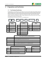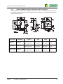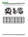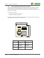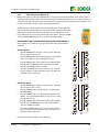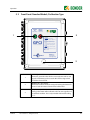
1
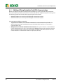
TM
User Manual
LifeGuard®
Ground Fault Circuit Interrupters
(GFCI)
NAE1085011 / 02.2013
TM
Bender Inc.
USA:
700 Fox Chase
Coatesville, PA 19320
Toll-Free: 800-356-4266
Phone: 610-383-9200
Fax: 610-383-7100
E-mail: [email protected]
Canada:
5810 Ambler Drive, Unit 1
Mississauga, ON L4W 4J5
Toll-Free: 800-243-2438
Phone: 905-602-9990
Fax: 905-602-9960
E-mail: [email protected]
Web: www.bender.org
NAE1085011, 02.2013
Replaces NAE1085010, 02.2012
© Bender Inc.
All rights reserved.
Content subject to change.
Table of Contents
1.
Introduction ..................................................................................................................... 5
1.1
1.2
1.3
LifeGuard Series Ground Fault Circuit Interrupter................................................................. 5
Build Variations and Instructions ................................................................................................. 5
“Compact” and “Standard” Versions........................................................................................... 5
2. Safety Instructions............................................................................................................ 7
3.
Preparation and Verification......................................................................................... 9
3.1
Part Number Verification ................................................................................................................ 9
4. Installation, Connection, and Adjustments ............................................................... 10
4.1
4.1.1
4.1.2
4.1.3
4.1.4
4.1.5
4.2
4.2.1
4.2.2
4.2.3
4.2.4
4.2.5
4.2.6
4.2.7
4.2.8
4.3
4.4
4.4.1
4.4.2
4.5
4.5.1
4.5.2
4.5.3
4.5.4
4.5.5
LifeGuard
Mounting ............................................................................................................................................
Enclosure/Backplate Sizes ............................................................................................................
Mounting NEMA 4X Polycarbonate Enclosure (4X-P-CH Option)..................................
Mounting NEMA 4X Stainless Steel Enclosure (4X-SS-CH Option) ................................
Mounting NEMA 12 Painted Steel Enclosure (12-PA-CH Option) ..................................
Mounting Backplate-Only With No Enclosure (N Option) ................................................
Wiring...................................................................................................................................................
Wiring: Single-Phase, Two Wire (L1, N) - Standard Models...............................................
Wiring: Three-Phase, Three-Wire (L1, L2, L3) - Standard Models....................................
Wiring: Three-Phase, Four-Wire (L1, L2, L3, N) - Standard Models.................................
Wiring: 240Y/120 VAC (L1, L2, N) - Standard Models..........................................................
Wiring: Single-Phase, Two Wire (L1, N) - Compact Models...............................................
Wiring: Three-Phase, Three Wire (L1, L2, L3) - Compact Models ....................................
Wiring: Three-Phase, Four Wire (L1, L2, L3, N) - Compact Models .................................
Wiring: 240Y/120 VAC (L1, L2, N) - Compact Models..........................................................
Additional Wiring: Backplate Only, No Communication ...................................................
Additional Wiring: Backplate Only, With Communication ...............................................
Option 1: Single / Isolated Device Installation (MK1500-D) .............................................
Option 2: Multiple, Interconnected Installation (COM460IP / MK2430) ......................
Field Adjustments............................................................................................................................
Field Adjustments: Option “6” ....................................................................................................
Field Adjustments: Option “20”..................................................................................................
Field Adjustments: Option “A”....................................................................................................
Field Adjustments: Option “B” ....................................................................................................
Field Adjustments: Option “C” ....................................................................................................
© 2012 Bender Inc. All Rights Reserved
10
10
10
11
12
13
14
15
16
17
18
19
20
21
22
23
24
25
26
29
29
29
30
31
32
3
4.5.6
Field Adjustments: Option “D” ................................................................................................... 33
5. Operation ......................................................................................................................... 34
5.1
5.2
5.3
5.4
5.5
5.5.1
5.5.2
5.6
5.6.1
5.6.2
5.6.3
4
Front Panel: Compact Models.....................................................................................................
Front Panel: Standard Models, Pushbutton Type ...............................................................
Front Panel: Standard Models, Digital Display Type...........................................................
Apply Power To the GFCI..............................................................................................................
Procedure for Performing a Functional Test .........................................................................
Functional Test: Options 6 and 20.............................................................................................
Functional Test: Options A, B, C, and D ...................................................................................
Error Codes ........................................................................................................................................
Error Codes: Options 6, 20............................................................................................................
Error Codes: Options A, B..............................................................................................................
Error Codes: Options C, D .............................................................................................................
34
35
36
37
37
37
37
38
38
38
38
© 2012 Bender Inc. All Rights Reserved
LifeGuard
Introduction
1.
Introduction
1. 1
LifeGuard Series Ground Fault Circuit Interrupter
LifeGuard series Ground Fault Circuit Interrupters (GFCIs) are designed to detect and interrupt hazardous
ground fault currents in grounded electrical systems. The GFCI is installed in-line between the power source
and electrical load(s). If a ground fault is detected, the integrated contactor will interrupt the power conductors of the circuit. The GFCI may then be manually reset once the fault has been cleared.
Standard LifeGuard GFCIs are packaged in a NEMA rated enclosure, with options including NEMA 4X polycarbonate and NEMA 4X stainless steel. LifeGuard GFCIs may also be ordered on the backplate only with no
enclosure, to be integrated into existing enclosures / cabinets.
This manual covers standard LifeGuard models up to 100 A rated load current. For higher rated builds, as well
as builds with customized options outside the scope of this manual, contact the manufacturer.
1. 2
Build Variations and Instructions
LifeGuard GFCIs are built-to-order systems. Variations exist based on the type of build and the system it is utilizedon. When installing and using the device, follow the correct instructions based on the device purchased
and the system specifications. Refer to Section 1.3 and Section 3 of this manual for more information on variations between models.
Standards listing of these devices vary with configuration and system parameters. Refer to Section X.X to
locate the information specific to the ordered model.
Possible variations include, but are not limited to:
•
System voltage and load ampere rating
•
Number of system conductors / poles
•
Trip level setting (adjustable or fixed) and time delay (fixed inverse time curve or adjustable
•
Enclosure type, or on backplate only
•
Push button type front or digital display front
•
Compact or standard model (see section 1.3)
1. 3
“Compact” and “Standard” Versions
Throughout this manual, references to “compact” and “standard” versions of the LifeGuard will appear. Compact LifeGuard GFCIs use a small enclosure and have special wiring requirements. The compact version of the
GFCI meets the following requirements:
•
20 A load ampere rating
•
Line-to-line voltage of 240 VAC or below
•
Have option “6” or “20” for a trip level and utilize the RCMA426H ground fault module
•
Have push button type front only (no digital display)
All other versions are referred to as the “standard” version throughout this manual.
LifeGuard
© 2013 Bender Inc. All Rights Reserved
5
Introduction
This page left intentionally blank.
6
© 2013 Bender Inc. All Rights Reserved
LifeGuard
Safety Instructions
2. Safety Instructions
!
DANGER
Hazard of Electric Shock, Burn, or Explosion
Only qualified maintenance personnel shall operate or service this equipment. These instructions should not
be viewed as sufficient for those who are not otherwise qualified to operate or service this equipment. This
document is intended to provide accurate information only. No responsibility is assumed by BENDER for any
consequences arising from use of this document.
Turn OFF all sources of electrical power before performing any inspections, tests, or service on this equipment. Assume all circuits are live until they have been properly de-energized, tested, grounded, and tagged.
Failure to do so will result in equipment damage, severe personal injury, or death.
Proper operation of this equipment depends on proper installation. Neglecting fundamental installation
techniques will result in equipment damage, severe personal injury, or death.
Do not make any modifcations to this equipment. Failure to do so will result in equipment damage or personal injury.
Only use manufacturer’s and manufacturer recommended accessories with this equipment. Failure to do so
may damage the equipment beyond repair.
For installation in a wet location, the ground fault circuit interrupter must be in a weatherproof enclosure
rated for the environment. Observe all national and local electrical code and standard requirements when
installing this equipment. Failure to do sill will result in equipment damage or severe personal injury.
Do not install the ground fault circuit interrupter on life support equipment. Failure to observe this precaution will result in severe personal injury or death.
The ground fault circuit interrupter provides ground fault protection only. It does NOT provide short circuit or
overload protection.
LifeGuard
© 2013 Bender Inc. All Rights Reserved
7
Safety Instructions
This page left intentionally blank.
8
© 2013 Bender Inc. All Rights Reserved
LifeGuard
Preparation and Verification
3.
Preparation and Verification
3. 1
Part Number Verification
LifeGuard GFCIs are customized to the system they are used on. The part number ordered details important
system information such as system voltage / amperes, trip level rating, etc. Before installing the GFCI, verify
that the received device is correct based on the system parameters. An incorrect part number may lead to
improper operation or damage to the equipment. A sample part number is given below with available
options.. Instructions for installation as well as available adjustments will vary based on the model - refer to
the appropriate section for more information.
Listing information may be found in section 4.3, “Field Adjustments.”
LG
100
-
480
-
3/3
Code 1:
Load Amperes
-
-
20
4X - P - CH
Code 2:
System Voltage (L-L)
-
D
Code 3:
Phases
20
20 amperes
120
120 volts
1/2
1ph, 2w (L1, N)
40
40 amperes
208
208 volts
1/3
1ph, 3w (L1, L2, N)
60
60 amperes
240
240 volts
3/3
3ph, 3w (L1, L2, L3)
80
80 amperes
277
277 volts
3/4
3ph, 4w (L1, L2, L3, N)
100
100 amperes
480
480 volts
575
575 volts
600
600 volts
Code 4: Trip Level, Detection Capability, Time Delay
6
6 mA fixed, AC/DC fault detection, fixed inverse time curve
20
20 mA fixed, AC/DC fault detection, fixed inverse time curve
A
6-600 mA adjustable, AC only fault detection, 0-10 s adjustable time delay
B
10 mA - 10 A adjustable, AC only fault detection, 0-10 s adjustable time delay
C
10 - 500 mA adjustable, AC/DC fault detection, 0-10 s adjustable time delay
D
30 mA - 3 A adjustable, AC/DC fault detection, 0-10 s adjustable time delay
Code 5: Enclosure
Code 6: Options
4X-P-CH
NEMA 4X polycarbonate enclosure
Blank
No options
4X-SS-CH
NEMA 4X stainless steel enclosure
S
E-stop button
12-PA-CH
NEMA 12 painted steel enclosure
D
Digital display
N
No enclosure, pre-built on backplate
LifeGuard
© 2013 Bender Inc. All Rights Reserved
9
Installation, Connection, and Adjustments
4. Installation, Connection, and Adjustments
4. 1
Mounting
4.1.1
Enclosure/Backplate Sizes
For each type of enclosure, three different sizes are available. Refer to section 1.3 for information on “compact” and “standard” GFCI nomenclature requirements. Refer to the applicable section on the following
pages for dimensions and instructions.
4.1.2
Mounting NEMA 4X Polycarbonate Enclosure (4X-P-CH Option)
The standard enclosure for LifeGuard GFCIs is a NEMA 4X polycarbonate enclosure. The enclosure includes
mounting feet and separate instructions on wall-mounting the enclosure. Refer to these instructions for more
information. Dimensions below are in inches (mm).
GFCI Type
10
Enclosure
AxB
C
D
E
F
G
Compact
8x6x4
6.25” x 4.25”
(159 x 108)
8.75”
(222.5)
6.75”
(171.5)
9.4”
(239)
5.7”
(145)
8.3”
(211)
Standard
12x10x6
10.25” x 8.25”
(260.5 x 209.5)
12.75”
(324)
10.75”
(273)
13.4”
(340)
7.7”
(195.5)
12.3”
(312.5)
100 A models
14x12x6
12.25” x 10.25”
(311 x 260.5)
14.75”
(375)
12.75”
(324)
15.4”
(391)
7.7”
(195.5)
14.3”
(363)
© 2013 Bender Inc. All Rights Reserved
LifeGuard
Installation, Connection, and Adjustments
4.1.3
Mounting NEMA 4X Stainless Steel Enclosure (4X-SS-CH Option)
LifeGuard GFCIs are also available in a NEMA 4X stainless steel enclosure. The enclosure includes separate
instructions on wall-mounting the enclosure. Refer to these instructions for more information. Dimensions
below are in inches (mm).
GFCI Type
Enclosure
AxBxC
DxE
GxH
J
Compact
12x12x6
12” x 12” x 6”
(305 x 305 x 152)
10.2” x 10.2”
(259 x 259)
10.5” x 10.5”
(267 x 267)
6”
(152)
Standard
16x12x6
16” x 12” x 6”
(406 x 305 x 152)
14.2” x 10.2”
(361 x 259)
14.5” x 10.5”
(368 x 267)
8”
(203)
100 A models
20x16x8
20” x 16” x 8”
(508 x 406 x 203)
18.2” x 14.2”
(462 x 361)
18.5” x 14.5”
(470 x 368)
10”
(254)
LifeGuard
© 2013 Bender Inc. All Rights Reserved
11
Installation, Connection, and Adjustments
4.1.4
Mounting NEMA 12 Painted Steel Enclosure (12-PA-CH Option)
LifeGuard GFCIs are also available in a NEMA 12 painted steel enclosure. The enclosure includes separate
instructions on wall-mounting the enclosure. Refer to these instructions for more information. Dimensions
below are in inches (mm).
GFCI Type
12
Enclosure
AxBxC
DxE
GxH
J
Compact
12x12x6
12” x 12” x 6”
(305 x 305 x 152)
10.2” x 10.2”
(259 x 259)
10.5” x 10.5”
(267 x 267)
6”
(152)
Standard
16x12x6
16” x 12” x 6”
(406 x 305 x 152)
14.2” x 10.2”
(361 x 259)
14.5” x 10.5”
(368 x 267)
8”
(203)
100 A models
20x16x8
20” x 16” x 8”
(508 x 406 x 203)
18.2” x 14.2”
(462 x 361)
18.5” x 14.5”
(470 x 368)
10”
(254)
© 2013 Bender Inc. All Rights Reserved
LifeGuard
Installation, Connection, and Adjustments
4.1.5
Mounting Backplate-Only With No Enclosure (N Option)
This section applies to LifeGuard models purchased without an enclosure, pre-assembled on a backplate.
Backplate-only models are typically integrated into existing cabinets or machinery. The GFCI must be
mounted in a location suitable to protect live electrical equipment and rated for the environment. Use four
(4) #10 screws for mounting.
Vertical clearance is as follows:
•
Models under 100 A load current: 6” (152 mm)
•
100 A load current models: 8” (203 mm)
Along with the system conductor wiring instructions in Section 4.2, additional wiring instructions for backplate-only models are found in Section 4.3 and Section 4.4.
A
C
LifeGuard
AxB
CxD
Compact
5.5” x 6.75”
(140 x 171.5)
4.875” x 6.5”
(124 x 165)
Standard
8.75” x 10.5”
(222 x 267)
8.25” x 10.25”
(210 x 260)
100 A models
10.75” x 12.75”
(273 x 324)
© 2013 Bender Inc. All Rights Reserved
B
D
GFCI Type
13
Installation, Connection, and Adjustments
4. 2
Wiring
LifeGuard GFCIs are installed in series with the main circuit, in between the source of power and the equipment load(s). Connection of the main circuit conductors varies based on number of conductors and system
voltage. Backplate-only options require additional control circuit connections.
DANGER
Turn off all sources of electrical power before installing this
equipment. Observe all local, state and national codes, standards and regulations when installing this equipment. Failure to do so will result in equipment damage, severe
personal injury, or death.
Locate the correct wiring diagram in the table below. In general, the following steps must be taken and
observed (refer to section 1.3 for differences between “compact” and “standard” models):
•
Compact versions utilize a ground fault monitor with a built-in current transformer. Labeled landing terminals are provided for line connections. Load side connections are landed on the contactor itself.
•
For standard models, all active conductors, including the neutral if it is being used, must be brought
through the current transformer, and landed on the line side of the contactor. All active conductors are
then brought out from the load side of the contactor to the load / remaining branch of the circuit.
•
The ground conductor wire is landed on the ground lug on the backplate. The ground wire is NOT routed
through the current transformer.
Conductors
(NOT Including Ground)
GFCI Type
Wiring
Diagram
120 VAC
1 ph / 2 w (L1, N)
Compact
page 19
120 VAC
1 ph / 2 w (L1, N)
Standard
page 15
208 VAC
3 ph / 3 w (L1, L2, L3)
Compact
page 20
208 VAC
3 ph / 3 w (L1, L2, L3)
Standard
page 16
208/120 VAC
3 ph / 4 w (L1, L2, L3, N)
Compact
page 21
208/120 VAC
3 ph / 4 w (L1, L2, L3, N)
Standard
page 17
240/120 VAC
1 ph / 3 w (L1, L2, N)
Compact
page 22
240/120 VAC
1 ph / 3 w (L1, L2, N)
Standard
page 18
277 VAC
1 ph / 2 w (L1, N)
Standard
page 15
480 VAC
3 ph / 3 w (L1, L2, L3)
Standard
page 16
3 ph / 4 w (L1, L2, L3, N)
Standard
page 17
3 ph / 3 w (L1, L2, L3)
Standard
page 16
3 ph / 4 w (L1, L2, L3, N)
Standard
page 17
Voltage
480/277 VAC
600 VAC
600/346 VAC
14
© 2013 Bender Inc. All Rights Reserved
LifeGuard
Installation, Connection, and Adjustments
4.2.1
Wiring: Single-Phase, Two Wire (L1, N) - Standard Models
Connection Legend:
Incoming
Line Side
Line Side
Landing
Load Side
Landing
Outgoing
Load Side
Phase L1
Contactor Line Side 1L1
Contactor Load Side 2T1
Load Phase L1
Neutral (N)
Contactor Line Side 3L2
Contactor Load Side 4T2
Neutral (N)
Ground Lug
Ground Lug
Ground at Load
Ground
LifeGuard
© 2013 Bender Inc. All Rights Reserved
15
Installation, Connection, and Adjustments
4.2.2
Wiring: Three-Phase, Three-Wire (L1, L2, L3) - Standard Models
Connection Legend:
Incoming
Line Side
16
Line Side
Landing
Load Side
Landing
Outgoing
Load Side
Phase L1
Contactor Line Side 1L1
Contactor Load Side 2T1
Load Phase L1
Phase L2
Contactor Line Side 3L2
Contactor Load Side 4T2
Load Phase L2
Phase L3
Contactor Line Side 5L3
Contactor Load Side 6T3
Load Phase L3
Ground
Ground Lug
Ground Lug
Ground At Load
© 2013 Bender Inc. All Rights Reserved
LifeGuard
Installation, Connection, and Adjustments
4.2.3
Wiring: Three-Phase, Four-Wire (L1, L2, L3, N) - Standard Models
Connection Legend:
Incoming
Line Side
Line Side
Landing
Load Side
Landing
Outgoing
Load Side
Phase L1
Contactor Line Side 1L1
Contactor Load Side 2T1
Load Phase L1
Phase L2
Contactor Line Side 3L2
Contactor Load Side 4T2
Load Phase L2
Phase L3
Contactor Line Side 5L3
Contactor Load Side 6T3
Load Phase L3
Neutral (N)
Contactor Line Side 7L4
Contactor Load Side 8T4
Neutral (N)
Ground Lug
Ground Lug
Ground At Load
Ground
LifeGuard
© 2013 Bender Inc. All Rights Reserved
17
Installation, Connection, and Adjustments
4.2.4
Wiring: 240Y/120 VAC (L1, L2, N) - Standard Models
Connection Legend:
Incoming
Line Side
18
Line Side
Landing
Load Side
Landing
Outgoing
Load Side
Phase L1
Contactor Line Side 1L1
Contactor Side 2T1
Load Phase L1
Neutral (N)
Contactor Line Side 3L2
Contactor Load Side 4T2
Neutral (N)
Phase L2
Contactor Line Side 5L3
Contactor Load Side 6T3
Load Phase L2
Ground
Ground Lug
Ground Lug
Ground At Load
© 2013 Bender Inc. All Rights Reserved
LifeGuard
Installation, Connection, and Adjustments
4.2.5
Wiring: Single-Phase, Two Wire (L1, N) - Compact Models
Connection Legend:
Incoming
Line Side
Line Side
Landing
Load Side
Landing
Outgoing
Load Side
Phase L1
Terminal L1
Contactor Load Side 2T1
Load Phase L1
Neutral (N)
Terminal N
Contactor Load Side 4T2
Neutral (N)
Ground Terminal
Ground Lug
Ground at Load
Ground
LifeGuard
© 2013 Bender Inc. All Rights Reserved
19
Installation, Connection, and Adjustments
4.2.6
Wiring: Three-Phase, Three Wire (L1, L2, L3) - Compact Models
Connection Legend:
Incoming
Line Side
20
Line Side
Landing
Load Side
Landing
Outgoing
Load Side
Phase L1
Terminal L1
Contactor Load Side 2T1
Load Phase L1
Phase L2
Terminal L2
Contactor Load Side 4T2
Load Phase L2
Phase L3
Terminal L3
Contactor Load Side 6T3
Load Phase L3
Ground
Ground Terminal
Ground Lug
Ground at Load
© 2013 Bender Inc. All Rights Reserved
LifeGuard
Installation, Connection, and Adjustments
4.2.7
Wiring: Three-Phase, Four Wire (L1, L2, L3, N) - Compact Models
Connection Legend:
Incoming
Line Side
Line Side
Landing
Load Side
Landing
Outgoing
Load Side
Phase L1
Terminal L1
Contactor Load Side 2T1
Load Phase L1
Phase L2
Terminal L2
Contactor Load Side 4T2
Load Phase L2
Phase L3
Terminal L3
Contactor Load Side 6T3
Load Phase L3
Neutral (N)
Terminal N
Contactor Load Side 8T4
Neutral (N)
Ground Terminal
Ground Lug
Ground at Load
Ground
LifeGuard
© 2013 Bender Inc. All Rights Reserved
21
Installation, Connection, and Adjustments
4.2.8
Wiring: 240Y/120 VAC (L1, L2, N) - Compact Models
Connection Legend:
Incoming
Line Side
22
Line Side
Landing
Load Side
Landing
Outgoing
Load Side
Phase L1
Terminal L1
Contactor Load Side 2T1
Load Phase L1
Neutral (N)
Terminal N
Contactor Load Side 4T2
Neutral (N)
Phase L2
Terminal L2
Contactor Load Side 8T4
Load Phase L2
Ground
Ground Terminal
Ground Lug
Ground at Load
© 2013 Bender Inc. All Rights Reserved
LifeGuard
Installation, Connection, and Adjustments
4. 3
Additional Wiring: Backplate Only, No Communication
Models on backplate only with no communication capability carry “-N” at the end of the part number.
Models pre-built in an enclosure come pre-wired for all indication, test, and reset functions. Backplate-only
models require additional wiring to complete these functions. Refer to the wiring diagram and table below.
NOTE: These terminals are NOT provided when using a module which supports digital communication. Modules which support communication connect only with a two-wire RS-485 connection to the MK1500-D
remote indicator. Refer to page 24 for more information.
Connection Legend:
Connections noted with an asterisk (*) below are provided with 120 VAC from the backplate.
Contact
LifeGuard
Description
Off.1 / Off.2
N/C contact / pushbutton, STOP function. Opening this contact will not allow the GFCI to close and energize the load
side.
Test.1 / Test.2
N/O contact / pushbutton, TEST function. Closing this contact for at least 2 seconds initiates a self-test.
On 1.1 / On 1.2
N/O contact / pushbutton, RESET function. Closing this contact provides reset functionality.
COM LED *
Common for indicator lights
Cir Trip *
TRIPPED light.
Load On*
ON light.
© 2013 Bender Inc. All Rights Reserved
23
Installation, Connection, and Adjustments
4. 4
Additional Wiring: Backplate Only, With Communication
Models on backplate only with no communication capability carry “-N-D” at the end of the part number.
This section applies to models not installed in an enclosure (installed on backplate only) and are using one of
the following ground fault modules which supports digital communication:
•
RCMA421H-DCB-2 (6 or 20 mA trip level with digital communication option)
•
RCMA426H-DCB-2 (6 or 20 mA trip level with digital communication option)
Two connection possibilities are possible:
•
Single device installations or installations where GFCIs are not connected to each other: This
option allows the pairing of an MK1500-D remote indicator. Refer to Section 4.4.1. If no remote is
required, skip this step.
•
24
Multiple device installation with RS-485 interconnection: This option allows for use of the MK2430
remote indicating station, as well as connecting to the COM460IP communication gateway to manage
devices remotely via either a web-browser based GUI or via Modbus/TCP. Refer to Section 4.4.2. If no
remote indicator or communication module is required, skip this step.
© 2013 Bender Inc. All Rights Reserved
LifeGuard
Installation, Connection, and Adjustments
4.4.1
Option 1: Single / Isolated Device Installation (MK1500-D)
This option is used when a single device is installed, or GFCIs are not interconnected to each other. One
MK1500-D remote may be paired with one GFCI. Multiple GFCIs may not be connected together with RS-485
using this method.
Test and reset functions are carried out in one of the following ways:
•
Using the test and reset pushbuttons located on the ground fault module
•
Connecting an MK1500-D remote indicator and using the built-in test and reset buttons
•
Connecting an MK1500-D remote indicator and connecting external test/reset pushbuttons
The MK1500-D duplicates indication and test/reset pushbutton functionality. Additionally, terminals are provided for external test and reset. Both are normally open (N/O) contacts.
Observe the following additional requirements:
•
Use shielded RS-485 cable, AWG 18 for connections “A” and “B.”
•
The red switch labeled “R” on the underside of the ground fault module must be switched to “ON” to
ensure proper RS-485 termination. Standard RS-485 cable length limitations apply.
•
External test and rest control connections are optional and not necessary for the built-in test and reset
functionality of the MK1500-D.
•
The MK1500-D requires an external supply voltage not supplied from the backplate, connected to terminals A1/A2. The supply voltage range is 100-240 VAC, 50/60 Hz.
Refer to the wiring diagram below for additional wiring required for the MK1500-D. For additional information on installation and use of the remote indicator, refer to MK1500-D installation manual. Do not modify
any other wiring on the backplate when installing the remote indicator.
RCMA421H-DCB-2
RCMA426H-DCB-2
T1
A1 A2
21 22
24
MK1500-D
T2
MK1500
A
B
GFCI-SERIES
RS-485 cable: twisted, shielded pair
POWER
ON
25
I
mA
50
75
CIRCUIT
TRIPPED
100
%
TEST
RESET
A
B
RESET
T/R
TEST
(Optional External
Test/Reset Connections)
A2
A1
To supply voltage
100-240 VAC
LifeGuard
© 2013 Bender Inc. All Rights Reserved
25
Installation, Connection, and Adjustments
4.4.2
Option 2: Multiple, Interconnected Installation (COM460IP / MK2430)
This option is used when multiple GFCIs shall be interconnected to each other. Connecting BENDER GFCIs
togehter with RS-485 offers several new features:
•
A single MK2430 remote indicating station which provides alarm notification for all connected GFCIs
from one remote. Refer to MK2430 user manual for more information on installation and setup.
•
Connection to BENDER’s COM460IP communication gateway, which allows for remote management of
connected BENDER devices via either a web browser-based GUI on a standard Ethernet network, or via
Modbus/TCP. Refer to steps below as well as the COM460IP user manual for more information.
LifeGuard GFCIs support connecting to BENDER’s COM460IP communication module. The COM460IP provides a GUI interface for managing BENDER devices across a standard Ethernet network, as well as functioning as a Modbus/TCP gateway. Connection between panels is made using a two-wire RS-485 connection
(standard RS-485 limitations apply).
Follow the steps below to wire and set up the communication system. Refer to COM460IP user manual for
more detailed information on installation, setup, and use of the communication gateway.
Step 1: Wiring
A two-wire RS-485 connection is required across all LifeGuard panels and the COM460IP. Connections are
made at each device’s A and B terminals. Connections are made in a daisy chain formation and made directly
to the A and B terminals on the internal RCMA421H/RCMA426H monitor. Refer to the diagram below.
A termination resistor DIP switch must be activated at the devices at the beginning and end of the chain.
Devices in the middle will have this switch set to OFF.
RS-485
Termination
on
off
RS-485
Termination
on
off
R
R
LifeGuard Panel 1
Internal RCMA Monitor
LifeGuard Panel 2
Internal RCMA Monitor
RS-485
Termination
RS-485
Termination
on
off
on
off
R
R
MK2430
Remote Station
COM460IP
.
.
.
The maximum total length of the RS-485 with no repeater is 3900 ft (1200 m). For greater distances, an RS-485
repeater is required (BENDER part number DI-1DL).
Connection of an MK2430 remote indicating station is optional. The MK2430 provides alarm notification as
well as test functionality for multiple-connected GFCIs from a single module. For more information on setting
up an MK2430 remote, refer to the MK2430 user manual.
26
© 2013 Bender Inc. All Rights Reserved
LifeGuard
Installation, Connection, and Adjustments
Step 2: Set RS-485 Addressing
The RS-485 bus operates on a master/slave principle. Each device on the RS-485 communication bus requires
a unique, sequential address. Set the COM460IP to address 1 to set it as the master. Refer to COM460IP user
manual for information on setting the RS-485 address.
For the remaining LifeGuard panels, open the enclosure to view the RCMA421H/RCMA426H inside. Beginning with number 2, set the RCMA in each panel to a unique, sequential address. Follow the steps below.
DO NOT CHANGE ANY OTHER SETTINGS OTHER THAN THOSE LISTED BELOW.
1 Hold the MENU button for several seconds. A flashing “INF” will appear on the screen.
2
Press the DOWN button once. A flshing “ADR” wil appear on the screen. Press the menu button.
3
A number will appear on the middle of the screen. “ADR” will appear below it flashing. Press the MENU
button.
4
The number in the middle will now flash. Press the UP and DOWN buttons to set the value to the desired
RS-485 address. Press the MENU button to confirm.
5
Hold the MENU button down for several seconds to return to the “ADR” screen. Repeat this step to exit
the main menu and return to the main screen.
6
Repeat steps 1 through 5 for each remaining panel, incrementing the address each time.
Step 3: Set Up Interfacing
The COM460IP may be used as an interface for managing BENDER devices across a standard Ethernet network, or it may be used as a gateway to a Modbus/TCP network.
Connecting to a Modbus/TCP Network
The COM460IP acts as a gateway between BENDER’s RS-485 network and a Modbus/TCP network. The
COM460IP acts as a slave on a Modbus/TCP network. Data is queried from a Modbus/TCP master to the
COM460IP, which then retrieves data from the BENDER RS-485 network. Connect the COM460IP to the Modbus/TCP network using one of the available Ethernet ports. Refer to COM460IP user manual for detailed information on utilizing the Modbus/TCP function, including setup and relevant registers for RCMA421H /
RCMA426H devices.
Connecting to an Ethernet Network
Connect the COM460IP to a network using one of the available Ethernet ports. If connecting to a network
which supports DHCP, the COM460IP will automatically aquire an IP address. Otherwise, IP addressing will
need to be manually set. Once completed, any computer on the network may connect to the GUI by opening
a web browser and typing in the IP address of the COM460IP (Silverlight plugin is required).
Once accessed, all devices connected on the RS-485 network may be managed. Note that LifeGuard panels
will appear in the list as RCMA421H or RCMA426H, depending on panel type. Refer to COM460IP user manual
for more detailed information on using the user interface.
Refer to the following page for interface samples. Note that the BENDER communication bus is not limited to
Lifeguard panels - other BENDER devices may connect to the network and be managed at the COM460IP
interface.
LifeGuard
© 2013 Bender Inc. All Rights Reserved
27
Installation, Connection, and Adjustments
Below is a sample of the standard interface showing the status of a device.
Below is a sample of the COM460IP Option D, allowing for the visualization of the network and status of
BENDER connected devices:
28
© 2013 Bender Inc. All Rights Reserved
LifeGuard
Installation, Connection, and Adjustments
4. 5
Field Adjustments
Adjustable options such as the trip level and time delay vary by model. Code 4 of the part number as shown
in Section 3.1 determines what options are available. Refer to the table below for the section on how to
adjust any available options.
Code 4 (See Section 3.1)
4.5.1
Refer To
“6”
page 29
“20”
page 29
“A”
page 30
“B”
page 31
“C”
page 32
“D”
page 33
Field Adjustments: Option “6”
Models with option “6” utilize the RCMA421H or RCMA426H ground fault module. These models are fixed at a
6 mA trip level and use a fixed inverse time curve per UL 943. Neither is field adjustable. This monitor can
detect both AC and DC faults, and works on systems with variable frequency drives.
Models which use these devices and are used on electrical systems with a line-to-ground voltage of 150 VAC
or below are listed to UL 943 as Class A GFCIs for personnel protection. The Class A standard does not apply to
higher system voltages, however the same ground fault module and contactor are used to protect these systems, such as 480 VAC and 600 VAC systems. Models which utilize this option are UL 508 listed.
Refer to Section 5.1 for information on the front panel display for push button models, or Section 5.2 for information on versions which support communication and have the door mounted remote indicator.
4.5.2
Field Adjustments: Option “20”
Models with option “6” utilize the RCMA421H or RCMA426H ground fault module. These models are fixed at a
6 mA trip level and use a fixed inverse time curve per UL 943. Neither is field adjustable. This monitor can
detect both AC and DC faults, and works on systems with variable frequency drives.
Models which utilize this option are UL 508 listed.
Refer to Section 5.1 for information on the front panel display for push button models, or Section 5.2 for information on versions which support communication and have the door mounted remote indicator.
LifeGuard
© 2013 Bender Inc. All Rights Reserved
29
Installation, Connection, and Adjustments
4.5.3
Field Adjustments: Option “A”
Models with option “A” utilize the RCM470LY-7113 or equivalent ground fault monitor. These models allow
for adjustment of the trip level steplessly from 6 mA to 600 mA. An adjustable time delay is also available,
from 0 to 10 seconds. This monitor detects AC faults only, and is not compatible with systems with variable
frequency drives.
All adjustments are made using the DIP switches and potentiometers on the face of the monitor. Open the enclosure to view the
ground fault monitor and follow the instructions below to make
any necessary adjustments.
DO NOT CHANGE THE FIRST TWO DIP SWITCHES FROM THE
LEFT. These are essential for proper operation of the GFCI and
shall not be modified.
Alarm response range
6 - 60 mA
10 - 100 mA
20 - 200 mA
30 - 300 mA
40 - 400 mA
6
10
20
30
40
60 - 600 mA
Time delay
multiplier
•
Only one (or none) of the numbered DIP switches shall be active (down) at any time. This functions as the
“starting point” for the desired trip level. Once active, use the potentiometer “x mA” to act as a mutiplier
of this value, from x1 to x10.
•
For example, to use a trip level of 50 mA, press the “10” DIP switch down, and the remaining numbered
DIP switches up. Turn the potentiometer “x mA” halfway to 5.
•
Use the potentiometer “t/s” to adjust the trip level between 0 and 1 second. Use the last DIP switch on
the right to multiply this value by 10 if desired. For example, for a time delay of 5 seconds, adjust the “t/s”
potentiometer halfway to 0.5, and press the last DIP switch down to x10.
Models which utilize this option are UL 508 listed.
30
© 2013 Bender Inc. All Rights Reserved
LifeGuard
Installation, Connection, and Adjustments
4.5.4
Field Adjustments: Option “B”
Models with option “A” utilize the RCM470LY-13 or equivalent ground fault monitor. These models allow for
adjustment of the trip level steplessly from 10 mA to 10 A. An adjustable time delay is also available, from 0 to
10 seconds. This monitor detects AC faults only, and is not compatible with systems with variable frequency
drives.
All adjustments are made using the DIP switches and potentiometers on the face of the monitor. Open the enclosure to view the
ground fault monitor and follow the instructions below to make
any necessary adjustments.
DO NOT CHANGE THE FIRST TWO DIP SWITCHES FROM THE
LEFT. These are essential for proper operation of the GFCI and
shall not be modified.
Alarm response range
10 - 100 mA
30 - 300 mA
100 - 1000 mA
300 - 3000 mA
500 - 5000 mA
1 - 10 A
Time delay
multiplier
•
Only one (or none) of the numbered DIP switches shall be active (down) at any time. This functions as the
“starting point” for the desired trip level. Once active, use the potentiometer “x mA” to act as a mutiplier
of this value, from x1 to x10.
•
For example, to use a trip level of 50 mA, press the “10” DIP switch down, and the remaining numbered
DIP switches up. Turn the potentiometer “x mA” halfway to 5.
•
Use the potentiometer “t/s” to adjust the trip level between 0 and 1 second. Use the last DIP switch on
the right to multiply this value by 10 if desired. For example, for a time delay of 5 seconds, adjust the “t/s”
potentiometer halfway to 0.5, and press the last DIP switch down to x10.
Models which utilize this option are UL 508 listed.
LifeGuard
© 2013 Bender Inc. All Rights Reserved
31
Installation, Connection, and Adjustments
4.5.5
Field Adjustments: Option “C”
Models with option “C” utilize the RCMA420-D-2 or equivalent ground fault monitor. These models allow for
adjustment of the trip level steplessly from 10 mA to 500 mA. An adjustable time delay is also available, from
0 to 10 seconds. A digital display shows the measured fault current in real-time. This monitor detects both AC
and DC faults, and works on systems with variable frequency drives.
All adjustments are made using the three blue pushbuttons and the digital display located on the device. Open the enclosure to view the ground fault monitor
and follow the instructions below to make any necessary adjustments. Three
blue pushbuttons are present from left to right on the device - UP arrow, DOWN
arrow, and MENU/ENTER button. These are used to modify settings.
DO NOT MODIFY ANY SETTINGS OTHER THAN THOSE SHOWN BELOW. All
other settings are essential for proper operation of the GFCI and shall not be
modified.
Adjust Trip Level:
•
Hold the MENU button down for several seconds. A flashing
“AL” will appear on the screen.
•
Press the MENU button. A mA value will appear in the middle
of the screen, with “I 2” at the top right hand corner.
•
Press the MENU button. The number in the middle will flash.
•
Press the UP and DOWN buttons to reach the desired trip
level. Press the MENU button to confirm.
•
> 1.5 sec
< 1.5 sec
Hold down the MENU button for several seconds. The flashing “AL” will appear again. Repeat this step to exit the menu
and return to the main screen.
< 1.5 sec
T
< 1.5 sec
> 1.5 sec
> 1.5 sec
R
Set-Point Adjustment
= Flashing Symbol
Adjust Time Delay:
•
Hold the MENU button down for several seconds. A flashing
“AL” will appear on the screen.
•
Press the DOWN button until a flashing “t” is reached. Press
the MENU button.
•
Press the DOWN button once. A number will appear in the
middle, “t on” in the bottom left hand corner, and a “2” at the
top right hand corner.
•
Press the MENU button. The number in the middle will flash.
Press the UP and DOWN buttons to reach the desired trip
delay. Press MENU to confirm.
•
Hold down the MENU button for several seconds. The flashing “t” will appear again. Repeat this step to exit the menu
and return to the main screen.
> 1.5 sec
< 1.5 sec
< 1.5 sec
T
< 1.5 sec
> 1.5 sec
> 1.5 sec
R
Set-Point Adjustment
= Flashing Symbol
Models which utilize this option are UL 508 listed.
32
© 2013 Bender Inc. All Rights Reserved
LifeGuard
Installation, Connection, and Adjustments
4.5.6
Field Adjustments: Option “D”
Models with option “C” utilize the RCMA423-D-2 or equivalent ground fault monitor. These models allow for
adjustment of the trip level steplessly from 30 mA to 3 A. An adjustable time delay is also available, from 0 to
10 seconds. A digital display shows the measured fault current in real-time. This monitor detects both AC and
DC faults, and works on systems with variable frequency drives.
All adjustments are made using the three blue pushbuttons and the digital display located on the device. Open the enclosure to view the ground fault monitor
and follow the instructions below to make any necessary adjustments. Three
blue pushbuttons are present from left to right on the device - UP arrow, DOWN
arrow, and MENU/ENTER button. These are used to modify settings.
DO NOT MODIFY ANY SETTINGS OTHER THAN THOSE SHOWN BELOW. All
other settings are essential for proper operation of the GFCI and shall not be
modified.
Adjust Trip Level:
•
Hold the MENU button down for several seconds. A flashing
“AL” will appear on the screen.
•
Press the MENU button. A mA value will appear in the middle
of the screen, with “I 2” at the top right hand corner.
•
Press the MENU button. The number in the middle will flash.
•
Press the UP and DOWN buttons to reach the desired trip
level. Press the MENU button to confirm.
•
Hold down the MENU button for several seconds. The flashing “AL” will appear again. Repeat this step to exit the menu
and return to the main screen.
> 1.5 sec
< 1.5 sec
< 1.5 sec
T
< 1.5 sec
> 1.5 sec
> 1.5 sec
R
Set-Point Adjustment
= Flashing Symbol
Adjust Time Delay:
•
Hold the MENU button down for several seconds. A flashing
“AL” will appear on the screen.
•
Press the DOWN button until a flashing “t” is reached. Press
the MENU button.
•
Press the DOWN button once. A number will appear in the
middle, “t on” in the bottom left hand corner, and a “2” at the
top right hand corner.
•
Press the MENU button. The number in the middle will flash.
Press the UP and DOWN buttons to reach the desired trip
delay. Press MENU to confirm.
•
Hold down the MENU button for several seconds. The flashing “t” will appear again. Repeat this step to exit the menu
and return to the main screen.
> 1.5 sec
< 1.5 sec
< 1.5 sec
T
< 1.5 sec
> 1.5 sec
> 1.5 sec
R
Set-Point Adjustment
= Flashing Symbol
Models which utilize this option are UL 508 listed.
LifeGuard
© 2013 Bender Inc. All Rights Reserved
33
Operation
5. Operation
5. 1
Front Panel: Compact Models
2
1
3
34
1
POWER light / RESET button:
Illuminates green when the GFCI has received power and has not
tripped. A momuntary push resets the GFCI if it has tripped and
the fault has been cleared.
2
TRIPPED light / TEST button:
Illuminates red when the GFCI has tripped. Pushing this button for
at least 2 seconds initiates a functional test of the GFCI.
3
E-Stop button (OPTIONAL - OPTION “S” ONLY)
Pushing in the button will not allow the GFCI to start regardless of
ground fault condition. This is only included with models ending
in “-S.”
© 2013 Bender Inc. All Rights Reserved
LifeGuard
Operation
5. 2
Front Panel: Standard Models, Pushbutton Type
POWER
ON
CIRCUIT
TRIPPED
Push to Reset
Push to Test
2
1
OPERATION
GFCI
Ground Fault Circuit Interrupter
The GREEN “POWER ON” lamp
illuminates when power is available on the
load side.
The RED “CIRCUIT TRIPPED” lamp
illuminates when power is removed from
the circuit.
If the GFCI trips,clear the fault and press
the “Reset” button to resume operation.
TESTING
Press the “Test” button for > 2 seconds.
Unit must trip.
Press the “Reset” button for > 1 second.
Unit must reset.
Life
Guard
GFCI
Technical Support
Bender Inc.
Tel. (800) 356-4266
E-mail: [email protected]
3
LifeGuard
1
POWER light / RESET button:
Illuminates green when the GFCI has received power and has not
tripped. A momuntary push resets the GFCI if it has tripped and
the fault has been cleared.
2
TRIPPED light / TEST button:
Illuminates red when the GFCI has tripped. Pushing this button for
at least 2 seconds initiates a functional test of the GFCI.
3
E-Stop button (OPTIONAL - OPTION “S” ONLY)
Pushing in the button will not allow the GFCI to start regardless of
ground fault condition. This is only included with models ending
in “-S.”
© 2013 Bender Inc. All Rights Reserved
35
Operation
5. 3
Front Panel: Standard Models, Digital Display Type
1
MK1500
3
GFCI-SERIES
55
. .0
POWER
ON
25
2
I
mA
50
75
4
CIRCUIT
TRIPPED
100
%
TEST
5
RESET
6
36
1
Digital Display:
Shows the measured ground fault current in real-time.
2
LED Bar Graph:
Inidicates in % how close the GFCI is to tripping.
3
POWER light:
Illuminates green when the GFCI has received power and has not
tripped.
4
TRIPPED light:
Illuminates red when the GFCI has tripped.
5
RESET button:
A momuntary push resets the GFCI if it has tripped and the fault
has been cleared.
6
TEST button:
Pushing this button for at least 2 seconds initiates a functional test
of the GFCI.
© 2013 Bender Inc. All Rights Reserved
LifeGuard
Operation
5. 4
Apply Power To the GFCI
To apply power, close the circuit breaker / disconnect on the line side of the GFCI. The GFCI will immediately
power on. If there is no ground fault present on the load side, the green “Power ON” light will illuminate and
the load side will remain energized.
5. 5
Procedure for Performing a Functional Test
Performing a functional test of the LifeGuard GFCI will disengage the contactor and will interrupt power to
any loads on the load side of the contactor. Follow the steps below to perform a functional test.
BENDER recommends pressing the TEST button at least monthly to ensure proper operation of the GFCI.
5.5.1
Functional Test: Options 6 and 20
This section applies to GFCIs which have a Code 4 (See Section 3.1) of 6 or 20. Follow the steps below to perform a functional test of the GFCI:
•
Press and hold the TEST button for at least two (2) seconds. The GFCI must trip and the red “Circuit
Tripped” light will illuminate. The green “Power ON” light will no longer illuminate. The contactor will
open and no power will be present on the load side.
•
After the contactor opens, an internal self-test of the ground fault module will initiate. This takes approximately ten (10) seconds.
•
Once the self-test has completed, momuntarily press the RESET button. The GFCI must reset. The red
“Circuit Tripped” light will go out and the green “Power ON” light will illuminate. The contactor will
engage and power will be restored to the load side.
5.5.2
Functional Test: Options A, B, C, and D
This section applies to GFCIs which have a Code 4 (see Section 3.1) of A, B, C, or D. Follow the steps belo to
perform a functional test of the GFCI:
•
Press and hold the TEST button for at least two (2) seconds. The GFCI must trip and the red “Circuit
Tripped” light will illuminate. The green “Power ON” light will no longer illuminate. The contactor will
open and no power will be present on the load side.
•
LifeGuard
Momuntarily press the RESET button. The GFCI must reset. The red “Circuit Tripped” light will go out and
the green “Power ON” light will illuminate. The contactor will engage and power will be restored to the
load side.
© 2013 Bender Inc. All Rights Reserved
37
Operation
5. 6
Error Codes
Error codes are displayed on the ground fault module located inside the enclosure. For models with doormounted digital remote indicators, the remote will also display the error code.
5.6.1
Error Codes: Options 6, 20
E.01
Connector error: No current transformer or bad CT connection
Action: Check current transformer connections for open circuit (external CT version only). For models with built-in CT, contact the manufacturer.
The GFCI must be manually reset after clearing this error.
E.02
Connection error: No current transformer or bad CT connection (activated during internal self-test)
Action: Check current transformer connections for open circuit (external CT version only). For models with built-in CT, contact the manufacturer.
The GFCI must be manually reset after clearing this error.
E.03
Connection error: Current transformer short circuit
Action: Check current transformer for short circuit.
The GFCI must be manually reset after clearing this error.
E.04
Error K1/Q1 (after powering up the GFCI)
Action: Check contactor for welded contacts, sticking contacts, or
faulty release coil. Check current transformer connections (external CT
version only).
The GFCI must be manually reset after clearing this error.
E. > 0.4
5.6.2
Error Codes: Options A, B
Blinking
Alarm LED
5.6.3
Connection error: No current transformer or bad CT connection
Action: Check connections “k” and “l” between ground fault module
and current transformer. Check connections for short circuit or open
circuit.
The GFCI must be manually reset after clearing this error.
Error Codes: Options C, D
E.01
Connector error: No current transformer or bad CT connection
Action: Check current transformer for short circuit or open circuit.
The GFCI must be manually reset after clearing this error.
E.02
Connection error: No current transformer or bad CT connection (activated during internal self-test)
Action: Check current transformer for short circuit or open circuit.
The GFCI must be manually reset after clearing this error.
E. > 0.2
38
Contact the manufacturer.
Contact the manufacturer.
© 2013 Bender Inc. All Rights Reserved
LifeGuard
TM
Bender Inc.
USA:
700 Fox Chase
Coatesville, PA 19320
Toll-Free: 800-356-4266
Phone: 610-383-9200
Fax: 610-383-7100
E-mail: [email protected]
Canada:
5810 Ambler Drive, Unit 1
Mississauga, ON L4W 4J5
Toll-Free: 800-243-2438
Phone: 905-602-9990
Fax: 905-602-9960
E-mail: [email protected]
Web: www.bender.org