1
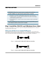
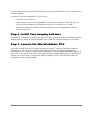
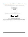
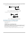
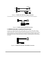
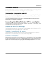
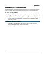
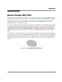
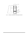
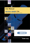
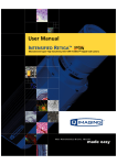
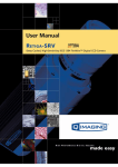
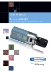
MicroPublisher RTV User’s Manual Applicability This document applies to the MicroPublisher RTV camera. For the latest updates, please visit WWW.QIMAGING.COM. Notice of Copyright Copyright 2003 Quantitative Imaging Corporation. All rights reserved. Unauthorized duplication of this document is prohibited. Trademarks and Proprietary Names QImaging, Retiga, and QCapture are trademarks of QImaging. Product names mentioned in this document may be trademarks or registered trademarks of QImaging or other hardware, software, or service providers and are used herein for identification purposes only. Microsoft and Windows are registered trademarks in the U.S. and other countries of Microsoft Corporation and are used herein for identification purposes only. Apple and Macintosh are registered in the U.S. and other countries by Apple Computer, Inc. and are used herein for identification purposes only. QImaging Corporation Address Information 4401 Still Creek Drive, Suite 100, Willingdon Business Park Burnaby, BC, Canada V5C 6G9 604.708.5061 WWW.QIMAGING.COM QImaging Technical Support Technical support is available to all registered users of QImaging products from 9am to 5pm Pacific Standard Time. [email protected] 604.708.5061 WWW.QIMAGING.COM/SUPPORT/CONTACT/ i CONTENTS MicroPublisher RTV User’s Manual ................................................................................. i INTRODUCTION ............................................................................................................. 1 Power Requirements ................................................................................................... 1 Host Requirements ...................................................................................................... 1 IEEE 1394 (FireWire) Interface ................................................................................. 2 Cables .......................................................................................................................... 2 Imaging Software for Your Camera ........................................................................... 2 INSTALLATION .............................................................................................................. 4 Step 1. Install the 1394 PCI card (Windows Users Only) .......................................... 4 Step 2. Install Your Imaging Software ....................................................................... 5 Step 3. Connect the MicroPublisher RTV .................................................................. 5 CAMERA BASICS ........................................................................................................... 9 Turning the Camera On and Off ................................................................................. 9 Connecting the MicroPublisher RTV to your Optics ................................................. 9 Understanding the LED Indicators ............................................................................. 10 Capturing Images with the MicroPublisher RTV ....................................................... 10 CARING FOR YOUR CAMERA ..................................................................................... 11 TROUBLESHOOTING ..................................................................................................... 12 Resolving Problems with the camera .......................................................................... 12 Unresolved Problems - Contacting QImaging Support .............................................. 13 GLOSSARY ...................................................................................................................... 14 ADDENDUM .................................................................................................................... 16 Neutral Density (ND) Filter ........................................................................................ 16 ii CHAPTER 1 INTRODUCTION The QImaging MicroPublisher with Real Time Viewing (RTV) delivers unsurpassed interactivity and productivity by combining ultra high resolution images with video like, full field of view frame rates of up to 30fps. Scanning, framing and focusing have never been easier than with the MicroPublisher RTV. The 30-bit color digitization produces high quality images of brightfield, dark-field and fluorescence work. For demanding low-light applications, the MicroPublisher RTV Cooled, minimizes thermal noise during long exposure times. With a IEEE 1394 FireWire™ digital interface the MicroPublisher RTV is easy to install requiring a single wire to connect the camera to a computer or laptop. The MicroPublisher RTV eliminates expenses, installation problems and inconveniences associated with framegrabbers and external power supplies. All cameras ship with Image Capture software. Large selections of specialty software applications are available from QImaging software partners and a Software Development Kit (SDK) is available upon request for interfacing the MicroPublisher RTV with custom software. MicroPublisher RTV comes in two models: • MicroPublisher RTV cooled - with a Peltier cooling system to lower the temperature 10° Celsius below ambient to reduce the effects of thermal noise for long integration times. • MicroPublisher RTV uncooled - for bright field imaging Power Requirements The MicroPublisher RTV can be powered through a single IEEE 1394 (FireWire) cable. • Power: Cooled MicroPublisher RTV = 7 watts Uncooled MicroPublisher RTV = 4 watts • Input voltage range: 8 - 24 volts Host Requirements For Windows PCs: • Pentium CPU, running at 300MHz. • 256 MB RAM. • Video card with 8 MB video memory capable of 32-bit color output. • Microsoft Windows 98 Second Edition, Windows Millennium Edition (ME), Windows 2000, or Windows XP Professional. 1 • If the PC is not equipped with a FireWire card, the supplied card must be installed. For Mac OS Computers: • PowerPC-based Macintosh with an OHCI compliant IEEE 1394 port (G4 and iMac models). • iMac models may not provide enough power to cooled cameras. QImaging’s IEEE 1394 HUB may be required to power the camera. Contact QImaging for ordering information. • Mac OS 9.1, 9.2 or X • 256 MB+ RAM • All the G4 and iMac models are equipped with a FireWire card. The supplied IEEE 1394 PCI is not required for Mac OS computers. IEEE 1394 (FireWire) Interface The MicroPublisher RTV is powered and controlled through an IEEE 1394 (FireWire) digital interface. A single FireWire connection from the camera to the computer allows full control of the camera and rapid image data transfer from the camera to the computer. Cables A 10-foot FireWire interface cable is included with the camera. One end of this cable connects to either of the available FireWire ports at the back of the camera; the other end of the cable plugs into your computer’s 6-pin FireWire port. Some computers have 4-pin FireWire ports. These ports may be used if they are OHCI compliant, but you will need to purchase a 4-pin to 6-pin FireWire cable from your local computer store. If you connect the MicroPublisher RTV to a 4-pin FireWire port, you likely need to use an external power supply. What is the difference between 4-pin and 6-pin FireWire ports? FireWire cables are available in two varieties: 4-pin and 6-pin. 6-pin FireWire cables are capable of providing both power and a communication interface between the camera and computer while 4-pin cables provide only a communication interface. Some laptop computers have 6-pin FireWire jacks that do not provide power. If your computer has such a port, you will have to power your MicroPublisher RTV by attaching an external power supply to the system. Imaging Software for Your Camera Industry Standard Imaging Applications The MicroPublisher RTV works with industry-standard Windows and Mac OS imaging software. Please go to the following URL for an up to date listing of third party software companies that support QImaging cameras. HTTP://WWW.QIMAGING.COM/ALLIANCES/ 2 QCapture Suite Software The MicroPublisher RTV operates on both Windows and Mac OS based systems. QCapture Suite Software for both systems is available at WWW.QIMAGING.COM. The easy-to-use QCapture software gives you complete control over the camera’s settings and image capture functions. QCapture Suite also includes a TWAIN-compliant interface that allows many Windows image-editing applications to acquire images using QImaging cameras. 3 CHAPTER 2 INSTALLATION IMPORTANT: Follow these steps in order to complete the installation. DO NOT CONNECT the camera until the camera driver is installed. 1. Windows PC users only: Install the IEEE 1394 PCI card - only if necessary. 2. Imaging Software - Install the software and drivers that your new QImaging camera needs to capture images. 3. MicroPublisher RTV - Connect the camera to your computer using the supplied IEEE 1394 cable. DO NOT CONNECT the camera until you have a functioning FireWire port in your computer and the camera driver is installed. Step 1. Install the 1394 PCI card (Windows Users Only) This step is for Windows PC users only. If you are installing the MicroPublisher RTV on a Mac OS computer, please skip to Step 2. Check your computer for an existing FireWire port: The MicroPublisher RTV connects to your Windows PC via a FireWire port. If you already have a FireWire port, you do not have to install the IEEE 1394 PCI card. Check the connectors at the back of your PC for a port that matches the FireWire ports on your camera (Figure 1 and Figure 2). Camera Computer Figure 1— 6-pin to 6-pin FireWire (IEEE 1394) Port connection Camera Computer Figure 2— 6-pin to 4-pin FireWire (IEEE 1394) Port connection 4 If your PC does not have a functioning FireWire port, you must install the IEEE 1394 PCI card that came with your camera. If necessary, install the supplied IEEE 1394 PCI card: • Shut down your computer. • Open the case, and install the supplied IEEE 1394 card into an empty PCI slot. See the user’s manual for your computer for complete instructions on installing new PCI cards. • Restart your computer. Windows should automatically install the appropriate software drivers for the card. Step 2. Install Your Imaging Software Once the IEEE 1394 card is installed in your computer, you are ready to install the FireWire drivers and imaging software. See your Imaging Software User’s Guide for complete installation instructions. Step 3. Connect the MicroPublisher RTV Once your imaging software is installed, connect your camera. There are two different types of connections. In most cases, the FireWire cable provides the necessary power required by the MicroPublisher RTV. However, if your camera is cooled you may need to provide additional power to the camera in one of the ways listed in the following figures. Most noteably, you will need to either connect your camera with a 1394l power supply or through an IEEE 1394 HUB. Both items are available from your QImaging dealer. 5 Connecting the camera to a PC/MAC desktop or MAC laptop Computer Perform the following for connecting your camera. • Remove the FireWire cable from the camera box, and plug one end of the cable into one of the camera’s FireWire sockets (either socket is fine). Figure 3— Camera FireWire Sockets. • Plug the other end of the cable into a FireWire port on your computer Camera Computer Figure 4— Desktop Computer FireWire Connection There are some cases when connecting to a PC or Mac desktop or Mac laptop computer where not enough power is supplied through the IEEE 1394 cable. If this is the case, you may receive an Error 6 Code 28 or the software not working consistently. In this case, external power must be delivered to the camera which can be accomplished by connecting the camera via one of the following methods. • Connection of an 1394 power supply with your camera is as follows: C om puter C am era 110/240 VA C Figure 5— FireWire and 1394 Power Supply Connection • Connection of a 1394 IEEE HUB with your camera is as follows: Camera Computer 1394 HUB 110/240 VAC Figure 6— FireWire and IEEE 1394 HUB Connection Connecting the camera to a PC laptop computer There are two common connection varieties for laptop computers; 1 Built-In Firewire port, or 2 PCMCIA Card. 1. Built-In 4-pin or 6-pin Firewire Port There are cases with PC laptops where a built-in 6-pin FireWire port is available. If this is the case with your computer, it is possible that the two power pins on the Firewire port have been disabled, allowing only data communications. If you have such a connection or if you have a built-in 4-pin connector, you will need to power the camera. If you purchased a 1394 power supply from QImaging, connect your camera as follows: 7 Computer Port2 Not Connected Port1 Camera 110/240 VAC Figure 7— FireWire and 1394 Power Supply Connection If you purchased an IEEE 1394 HUB, connect your camera as per the following figure. Camera Computer 1394 HUB 110/240 VAC Figure 8— FireWire and IEEE 1394 HUB Connection 2. PCMCIA Card with a 4-pin/6-pin Firewire Port In some cases, laptop computers have a firewire port from a PCMCIA card. Most of these PCMCIA cards allow an external connection directly to the card. If this is the case, and the PCMCIA connector is a 6-pin connector, then you should connect the power to your PCMCIA card and connect your camera as per Figure 9. However, if you have a 4-pin PCMCIA card Firewire port, then you will need to connect your camera in the configuration of either Figure 7 or Figure 8. Computer 110/240 VAC Figure 9— FireWire and 6-pin IEEE 1394 PCMCIA Connection 8 CHAPTER 3 CAMERA BASICS The MicroPublisher RTV’s image capture capabilities are controlled entirely by your imaging software. This chapter provides basic instructions for working with the camera itself. Turning the Camera On and Off To turn on the MicroPublisher RTV, all you need to do is to connect one end of your FireWire cable into one of the MicroPublisher RTV’s FireWire ports, and the other end of the cable to one of the FireWire ports on the computer’s PCI card. To turn off the MicroPublisher RTV, simple unplug the FireWire cable from either your camera’s FireWire port or the computer’s FireWire port. Connecting the MicroPublisher RTV to your Optics The MicroPublisher RTV connects directly to widely available C-mount optics. C-mount optics, which are standard on most microscopes and lenses. To attach the camera to a microscope: Carefully thread the camera onto the microscope’s C-mount adapter, rotating the camera until it is mounted securely. Use the microscope controls to adjust focus. To attach a C-mount lens to the camera: Carefully thread the C-mount lens onto the camera’s lens ring, rotating the lens in a clockwise direction until it is mounted securely. Use the lens controls to adjust focus. To attach F-mount optics: Before connecting your camera to F-mount optics, you first need to purchase a C to F mount adapter to allow the connection of F-mount optics. Carefully thread the male C-mount connector onto the camera’s lens ring. Next, connect your F-mount optics to the open connector of the C to F mount adapter until it is mounted securely. Use your optics controls to adjust focus. 9 Understanding the LED Indicators The LED indicators at the back of the camera give you important information about what your camera is doing: • GREEN: The green LED is the power indicator. This LED should always be lit when the camera is connected to your computer and is turned on. • RED: The red LED is the exposure/integration indicator. It flashes briefly when the CCD is exposing. • AMBER: The amber LED is the cooling indicator. It illuminates only on cooled cameras - and only when cooling is turned on. If you turn off cooling (a setting in your imaging software), the amber LED will turn off too. Capturing Images with the MicroPublisher RTV Consult your imaging application’s user’s manual for more details. 10 CHAPTER 4 CARING FOR YOUR CAMERA The MicroPublisher RTV camera requires no regular maintenance except occasional external cleaning of the CCD window (the glass window between the camera sensor and the microscope or lens). To clean the CCD window: CAUTION — The camera’s CCD sensor, and circuits are sensitive to static discharge. Ensure you are using a static strap or are completely grounded at all times to release any static energy before you clean the CCD window. • Use clean forced air (available at stores that sell cameras and computer cleaning supplies) to dust the CCD window. CAUTION — Do not use acetone. • If the image still appears dirty, gently wipe the face of the CCD window with a small amount of optical grade isopropyl alchohol and lens paper. • Apply forced air again to remove any loose particles. 11 CHAPTER 5 TROUBLESHOOTING Resolving Problems with the camera The Green LED is not lit. • Check all the cable connections. • Flip the switch at the back of the camera. • If your camera is still not lit, then your camera may not be receiving the required power. If you have a 1394 Power Supply or you have an IEEE 1394 HUB, connect the camera as listed in Step 3 of the “Introduction” Section. Image occasionally goes bright on one side or stays dark on one side Turn off the overhead lights in the room. Fluorescent lights may interact with the camera to create fluctuating image brightness. Hazy image or poor contrast • If you are using the camera on a microscope, check the magnification of the microscope coupler. Consult your microscope manufacturer to find the type of coupler that works optimally with the MicroPublisher RTV camera’s sensor. • Point the camera at something in the far distance. Loosen the set-screw of the C-mount ring (there are three: one on the side and two on the top). Adjust the C-mount ring until the image is in focus. Then tighten the set-screw so that the C-mount ring does not move. • This effect may also be caused by excessive infrared (IR) illumination. Verify that your camera or optical system is blocking the IR. Contact QImaging to order an IR filter. Images That Do Not Appear “Sharp” If the image does not seem “sharp,” check the format of the lens or the coupler being used on the microscope. MicroPublisher RTV is equivalent to the CCD sensor and requires the appropriate lens or coupler. An incorrect coupler on the microscope will not provide the correct field of view, and will reduce the light available to the sensor. 12 Unresolved Problems - Contacting QImaging Support If you are still unable to resolve your problem, contact QImaging Support for assistance in one of four ways: • Visit HTTP://WWW.QIMAGING.COM/SUPPORT/FAQ/ for a list of all frequently asked questions. Your issue may be resolved in one of these faqs. • Visit HTTP://WWW.QIMAGING.COM/SUPPORT/CONTACT/ and fill out a support form online with the details of your problem. • E-mail [email protected] with complete details of your problem (including Error Message and Code if possible), camera model, computer hardware configuration, and operating system. • Call +1-604-708-5061. Try to be in front of your computer when you call. 13 CHAPTER 6 GLOSSARY Binning Binning is a method of increasing camera speed and sensitivity to boost low signals. Binning causes the acquired image to be brighter and smaller, but the resolution will be lower as a result. Because the image is smaller, the image transfer time is reduced significantly. When you select a binning setting in your imaging software, the camera combines data from several pixels in the camera’s CCD into a single super pixel. For example, a 2x2 bin means that 2 pixels in the horizontal direction and 2 pixels in the vertical direction are combined to form one super pixel. C-Mount A standard threaded lens mount used to attach a camera to a microscope, or a separate lens to a camera. CCD Charge Coupled Device (abbr.) CCD Gain The amount of analog signal amplification. The gain is factory-optimized for the camera’s maximum dynamic range. Charge Coupled Device The light sensitive silicon chip near the optical interface of the camera that converts light intensities into electrical signals. These are typically made up of many pixel elements whose intensities are interpreted by imaging software to display an image on the screen. Dynamic Range The ratio of the saturation level of the CCD to the readout noise of the CCD camera system. Dynamic range is a measure of the ability of the camera to capture both bright and dark features in a single image. In general, the higher the camera’s dynamic range, the more information per pixel it can capture. Exposure The amount of time that light reaches the image sensor. Field of View The area visible through the camera’s optics. FireWire 14 See IEEE 1394. IEEE 1394 High bandwidth (40 megabytes/second - 1394a; 80 megabytes/second - 1394b) interface for connecting digital imaging, storage, and other devices to host computers. Image Intensifier An electro-optical vacuum tube which intensifies or amplifies on low light level images. Integration The active collection of photons as done by an image sensor. Iris A diaphragm in the lens that opens or closes to set the aperture (the amount of light that passes through the lens to the CCD). ms millisecond (abbr.); unit of measure for exposure time. ns nanosecond (abbr.); unit of measure for exposure time. Offset The offset value adjusts the CCD blacklevel relative to the analog-to-digital converter zero. It is factory-optimized for the camera’s maximum dynamic range. Pixel The smallest spatial element of a digital image. s second (abbr.); unit of measure for exposure time. us microsecond (abbr.); unit of measure for exposure time. 15 CHAPTER 7 ADDENDUM Neutral Density (ND) Filter Important Information to Ensure Accurate Color in Brightfield Images The Neutral Density or “ND” filter shown in Figure 10 that is included in your MicroPublisher RTV package is required on many microscopes to achieve the brilliant brightfield color images that MicroPublisher RTV is capable of creating. On many microscopes, a relatively high light intensity is required from the microscope’s light source to achieve the correct color temperature for brightfield imaging. The sensitivity of MicroPublisher RTV is sufficiently high that there are cases where images will appear saturated even at the minimum exposure time. In such cases, the preferred remedy is to introduce an ND filter into the light path to reduce the light incident on the CameraX's sensor without affecting the color temperature of the light.. If the ND filter is not used and the intensity of the microscope light source is reduced to prevent the camera from saturating, inaccurate color reproduction may result. Placing the ND filter in the optical path between the light source and the camera as shown in Figure 11 will allow the lamp temperature to be set correctly and also provide a mechanism to correctly set the colors of the MicroPublisher RTV camera. Figure 10— Neutral Density (ND) Filter) 16 C a m e ra S lid e N D F ilte r L ig h t S o u rc e M ic ro s c o p e O p tic a l P a th Figure 11— Placement of the ND filter in a Microscope environment 17