1
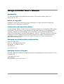
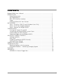
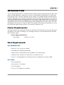
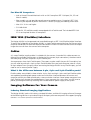
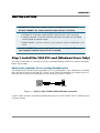
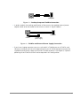
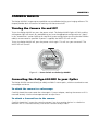
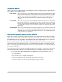
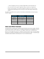
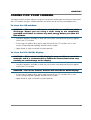
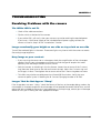
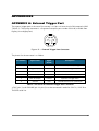
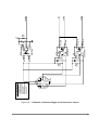
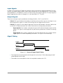
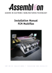
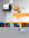
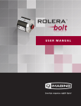
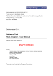
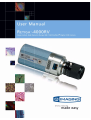
Retiga-4000RV User’s Manual Applicability This document applies to the Retiga-4000RV camera. For the latest updates, please visit WWW.QIMAGING.COM. Notice of Copyright Copyright 1999-2006 Quantitative Imaging Corporation. All rights reserved. Unauthorized duplication of this document is prohibited. Trademarks and Proprietary Names QImaging, Retiga, Rolera, QICAM, iGlo and QCapture are trademarks of QImaging. Product names mentioned in this document may be trademarks or registered trademarks of QImaging or other hardware, software, or service providers and are used herein for identification purposes only. Microsoft and Windows are registered trademarks in the U.S. and other countries of Microsoft Corporation and are used herein for identification purposes only. Apple and Macintosh are registered in the U.S. and other countries by Apple Computer, Inc. and are used herein for identification purposes only. QImaging Corporation Address Information 4190 Still Creek Drive, Suite 110, Willingdon Business Park Burnaby, BC, Canada V5C 6G9 604.708.5061 WWW.QIMAGING.COM QImaging Technical Support Technical support is available to all registered users of QImaging products from 9am to 5pm Pacific Standard Time. [email protected] 604.708.5061 WWW.QIMAGING.COM/SUPPORT/CONTACT/ i CONTENTS Retiga-4000RV User’s Manual ................................................................................i INTRODUCTION ......................................................................................................1 Power Requirements ........................................................................................1 Host Requirements ...........................................................................................1 IEEE 1394 (FireWire) Interface ..........................................................................2 Cables .............................................................................................................2 Imaging Software for Your Camera ..................................................................2 INSTALLATION ........................................................................................................4 Step 1. Install the 1394 PCI card (Windows Users Only) ....................................4 Step 2. Install Your Imaging Software ..............................................................5 Step 3. Connect the Retiga-4000RV .................................................................5 CAMERA BASICS ....................................................................................................7 Turning the Camera On and Off ......................................................................7 Connecting the Retiga-4000RV to your Optics .................................................7 Understanding the LED Indicators ....................................................................8 Capturing Images with the Retiga-4000RV .......................................................8 ADVANCED CAMERA CONTROLS ..........................................................................9 Cooling Capability ...........................................................................................9 iGlo (OLED) ......................................................................................................9 Triggering the Retiga-4000RV Extenally ............................................................11 Gain and Offset Controls .................................................................................13 CARING FOR YOUR CAMERA .................................................................................14 TROUBLESHOOTING ...............................................................................................15 Resolving Problems with the camera ................................................................15 Unresolved Problems - Contacting QImaging Support ......................................16 GLOSSARY .............................................................................................................17 APPENDICES ...........................................................................................................19 APPENDIX A: External Trigger Port ...................................................................19 ii CHAPTER 1 INTRODUCTION The QImaging Retiga-4000RV CCD digital camera has been specially engineered for low-light, high dynamic range applications. Sporting an 80,000e- full well capacity, combined with a three-stage Peltier device using an all-metal, hermetic-vacuum-sealed CCD chamber provides extreme dynamic range for applications such as chemiluminescence, live cell imaging and fl uorescence. The camera¡¯s software-selectable regulated cooling enables precise control in single-degree increments up to -30ªC. The Retiga-4000RV features a 4-megapixel CCD, 12-bit digital output, and an IEEE 1394 interface for enhanced connectivity and noise-shielding performance. Additionally, the camera comes with iGlo Technology, which features an Organic Light Emitting Diode (OLED) display that provides users with key information about camera settings in a convenient, ergonomic way. Power Requirements The Retiga-4000RV can be powered through a single IEEE 1394 FireWire 6-pin to 9-pin cable when the cooling is off. When the cooling is on, the Retiga-4000RV must be connected to the included external power supply. • Power Supply Specifications: Input Power: 30Watts, 12-24VDC Host Requirements For Windows PCs: • Pentium CPU, running at 300MHz. • 256 MB RAM (512MB RAM preferred). • Video card with 8 MB video memory capable of 32-bit color output. • Windows 2000, Windows XP Professional, or Windows XP x64. • If the PC is not equipped with a FireWire card, the included card must be installed. For Linux: • Intel x86 processor • Kernel version 2.6 or higher • raw1394 support. • Sun Java 1.4 or higher for installation. 1 For Mac OS Computers: • Intel or PowerPC-based Macintosh with an OHCI compliant IEEE 1394 port (G4, G5 and iMac models). • iMac models may not provide enough power to cooled cameras. QImaging’s IEEE 1394 HUB may be required to power the camera. Contact QImaging for ordering information. • Mac OS X 10.4.x and higher • 512 MB+ RAM • All the G4, G5 and iMac models are equipped with a FireWire card. The included IEEE 1394 PCI is not required for Mac OS computers. IEEE 1394 (FireWire) Interface The Retiga-4000RV can be powered and controlled through an IEEE 1394 (FireWire) digital interface. To realise the full benefits of the Retiga-4000RV, a single FireWire connection from the camera to the computer combined with the external power connection will allow full control of the camera and rapid image data transfer from the camera to the computer. Cables A 3 meter FireWire interface cable is included with the camera. One end of this cable connects to either of the available FireWire ports at the back of the camera (9-pin connection); the other end of the cable plugs into your computer’s 6-pin FireWire port. Some computers have 4-pin FireWire ports. These ports may be used if they are OHCI compliant, but you will need to purchase a 4-pin to 9-pin FireWire cable from your local computer store or a 4-pin to 6-pin adapter from QImaging. When connecting the Retiga-4000RV to any FireWire port, you will need to use an external power supply. What is the difference between 4-pin, 6-pin and 9-pin FireWire ports? FireWire cables are available in three varieties: 4-pin, 6-pin and 9-pin. 9-pin and 6-pin FireWire cables are capable of providing both power and a communication interface between the camera and computer while 4-pin cables provide only a communication interface. Some laptop computers have 6-pin FireWire jacks that do not provide power. If your computer has such a port, you will have to power your Retiga-4000RV by attaching the included external power supply to the system. Imaging Software for Your Camera Industry Standard Imaging Applications The Retiga-4000RV works with industry-standard Windows and Mac OS imaging software. Please go to the following URL for an up to date listing of third party software companies that support QImaging cameras. HTTP://WWW.QIMAGING.COM/PARTNERS/ 2 QCapture Suite Software The Retiga-4000RV operates on both Windows and Mac OS based systems. QCapture Suite Software for both systems is available at WWW.QIMAGING.COM. The easy-to-use QCapture software gives you complete control over the camera’s settings and image capture functions. QCapture Suite also includes a TWAIN-compliant interface that allows many Windows image-editing applications to acquire images using QImaging cameras. 3 CHAPTER 2 INSTALLATION IMPORTANT: Follow these steps in order to complete the installation. DO NOT CONNECT the camera until the camera driver is installed. 1. Windows PC users only: Install the IEEE 1394 PCI card - only if necessary. 2. Imaging Software - Install the software and drivers that your new QImaging camera needs to capture images. 3. Retiga-4000RV - Connect the camera to your computer using the included IEEE 1394 cable. DO NOT CONNECT the camera until you have a functioning FireWire port in your computer and the camera driver is installed. Step 1. Install the 1394 PCI card (Windows Users Only) This step is for Windows PC users only. If you are installing the Retiga-4000RV on a Mac OS computer, please skip to Step 2. Check your computer for an existing FireWire port: The Retiga-4000RV connects to your Windows PC via a FireWire port. If you already have a FireWire port, you do not have to install the IEEE 1394 PCI card. Check the connectors at the back of your PC for a port that matches the FireWire port of the connection shown in Figure 1. Camera Computer Figure 1 — 9-pin to 6-pin FireWire (IEEE 1394) Port connection If your PC does not have a functioning FireWire port, you must install the IEEE 1394 PCI card that came with your camera. 4 If necessary, install the included IEEE 1394 PCI card: • Shut down your computer. • Open the case, and install the included IEEE 1394 card into an empty PCI slot. See the user’s manual for your computer for complete instructions on installing new PCI cards. • Restart your computer. Windows should automatically install the appropriate software drivers for the card. Step 2. Install Your Imaging Software Once the IEEE 1394 card is installed in your computer, you are ready to install the FireWire drivers and imaging software. See your Imaging Software User’s Guide for complete installation instructions. Step 3. Connect the Retiga-4000RV Once your imaging software is installed, connect your camera. There are three different types of connections (1) through Windows or Macintosh 6-pin PCI card, (2) through windows or Macintosh laptop computer or (2) through Macintosh 9-pin connection. For the Retiga-4000RV, in order to operate the cooling, the camera must have the external power connected. However, should the cooling not be required, a single 9-pin to 6-pin connection will operate the camera sufficiently. In most cases, the FireWire cable provides the necessary power required by the Retiga-4000RV. However, if your camera is cooled you will need to provide additional power to the camera as shown in Figure 4 Connecting the QImaging Camera Perform the following for connecting your camera. • Remove the FireWire cable from the camera box, and plug one end of the cable (the 9-pin end) into one of the camera’s FireWire sockets (either socket is fine). FIREWIRE PORTS Figure 2 — Camera FireWire Sockets. • Plug the other end of the cable into a FireWire port on your computer 5 Camera Computer Figure 3 — Desktop Computer FireWire Connection • In order to obtain the cooling specification of the camera, the supplied external power adapter needs to be connected to the camera as shown in Figure 4 below. Computer Camera 110/240 VAC power supply Figure 4 — FireWire and External Power Supply Connection • If you have a laptop computer, you can use the built in FireWire port or a PCMCIA card. However, should you connect to a latpop computer you will still be required to connect the supplied external power supply to the camera in order to power it (see Figure 4). Optional powering of the PCMCIA card will not be required in this configuration 6 CHAPTER 3 CAMERA BASICS The Retiga-4000RV’s image capture capabilities are controlled entirely by your imaging software. This chapter provides basic instructions for working with the camera itself. Turning the Camera On and Off To turn the Retiga-4000RV on, press the power switch. The Retiga-4000RV lights will flash and the white power light will remain on, provided that you have the appropriate configuration of “Step 3” in the “Introduction” section. Refer to this step for all system configurations ensuring that the FireWire cable(s) are connected as specified. If power is supplied, the WHITE LED will turn on. To turn the Retiga-4000RV off, press the power switch again. This will turn your camera off. The WHITE LED will turn off. POWER SIWTCH Figure 5 — Power Switch on the Retiga-4000RV Connecting the Retiga-4000RV to your Optics The Retiga-4000RV connects directly to widely available C-mount optics, which are standard on most microscopes and lenses. To attach the camera to a microscope: Carefully thread the camera onto the microscope’s C-mount adapter, rotating the camera until it is mounted securely. Use the microscope controls to adjust focus. To attach a C-mount lens to the camera: Carefully thread the C-mount lens onto the camera’s lens ring, rotating the lens in a clockwise direction until it is mounted securely. Use the lens controls to adjust focus. 7 To attach F-mount optics: If you have a monochrome camera and you have purchased the optional color filter, then carefully thread the color filter to the C-mount ring on the camera. The opposite end of the color filter is a female F-mount connector. Carefully connect your F-mount optics to the open connector of the color filter until it is mounted securely. Use your optics controls to adjust focus. NOTE: If you did not purchase a color filter, then you will need to purchase a C to F mount adapter to allow the connection of F-mount optics. Your camera does not need to be monochrome in this situation. Understanding the LED Indicators The LED indicators at the back of the camera give you important information about what your camera is doing: • WHITE: The white LED is the power indicator. This LED should always be lit when the camera is connected to your computer and is turned on. • GREEN: The green LED is the exposure/integration indicator. It will stay illuminated for the duration of the exposure of the CCD and turn off when not exposing. • BLUE: The blue LED is the cooling indicator. It will flash while cooling down to the set temperature. When the temperature is locked and regulated, the blue LED will stay illuminated. It will turn off when cooling is turned off through software. Capturing Images with the Retiga-4000RV Consult your imaging application’s user’s manual for more details. 8 CHAPTER 4 ADVANCED CAMERA CONTROLS The Retiga-4000RV offers many advanced features. This section provides information on how to make the most of your QImaging camera. Cooling Capability The Retiga-4000RV offers the user the option of selecting the cooling temperature in one (1) degree increments. The maximum cooling of the Retiga-4000RV is -30ªC. iGlo (OLED) iGlo is the innovative combination of QImaging’s digital camera technology and an Organic Light Emitting Diode (OLED) display, providing camera setting information in an ergonomic way. No need to open your dialog box to record the settings of the camera, you can just look at the display! Figure 6 — iGlo Technology As shown above in Figure 6, iGlo displays seven (7) camera settings for easy visibility and verification. They are: 1 Temperature 2 Binning 3 Exposure 4 Monochrome or Color 5 Readout Speed 6 Bit Depth 7 Sensitivity Mode 1. Temperature The Retiga-4000RV has cooling capability down to -30ªC, changable in 1 degree increments. When the temperature is set through software, iGlo will show the temperature on the display, as shown below. 9 Figure 7 — Temperatur Indicator As the camera cools down, the cooling indicator icon will change to that of Figure 8a. Upon reaching the temperature requested, the camera will regulate or “lock” at that temperature and the indicator will change to that of Figure 8b. When cooling is turned off, iGlo will show the “off” icon as shown in Figure 8c. (c) (b) (a) Figure 8 — Cooling Indicators 2. Binning iGlo also shows the binning state of the Retiga-4000RV and will change instantaneously the moment the binning is changed in software. Figure 9 below indicates the binning state as shown by iGlo. Figure 9 — Binning Display 3. Exposure When the exposure is changed on Retiga-4000RV through software, iGlo will instantenously show it also. In Figure 10, the exposure is shown to be 16.38ms and will also show seconds, millseconds and microseconds when the camera is set to that exposure. Figure 10 — Exposure Display 4. Monochrome or Color When changing between color states, iGlo will show if the camera is set to Monochrome mode (Figure 11a) or RGB mode (Figure 11b). The icon will indicate RGB when a compatible RGB filter is in place and has been activated using the software. (a) (b) Figure 11 — Image Format Icons 10 5. Readout Speed Retiga-4000RV can be set to various readout speeds for better read noise performance. When changing the readout speed through software, iGlo will show the speed through the readout indicator. Examples of readout speed indicators are shown in Figure 12. (a) (b) Figure 12 — Readout Speed Icons 6.Bit Depth The Retiga-4000RV allows for two image capture formats, 8-bit or 12-bit images. Selecting the image capture mode in your software will automatically update iGlo with one of the icons shown in Figure 13. (a) (c) Figure 13 — Bit Depth Icons 7. Sensitivity Mode The Retiga-4000RV supports High Speed imaging for all types of imaging including brightfield, dark-field and fluorescence, offering high frame rates whilst keeping the anti-blooming protection. iGlo will display this mode (Figure 14) during normal operation. Figure 14 — High Sensitivity Icons Triggering the Retiga-4000RV Extenally Externally triggering the Retiga-4000RV provides a sophisticated method of imaging and synchronizing your camera to external parts of your system, offering advanced capabilities. To use this feature effectively, it is important to understand the operation and configuration of your camera. The External Trigger Port of the Retiga-4000RV is a 6-pin miniature circular DIN connector. This port accepts digital logic signals that are used to control the camera's integration. The External Trigger Port is optically isolated from the camera's electronics. For this reason, the user must provide power to the External Trigger Port. See Appendix A for a pinout and schematic diagram of the External Trigger Port. In externally triggered modes of operation, the user inputs a pulse on the External Trigger Port that controls the camera's integration in one of two ways depending on the triggering mode. 11 Triggering Modes When using External Triggering,there are three different types of triggering modes: Edge High/Low, Pulse High/Low and Strobe High/Low. Edge mode: allows the camera to start integrating on the rising or falling edge of the trigger pulse with the integration time controlled internally by the camera. Using this method allows you to externally trigger the camera as fast as possible, and allows you to take advantage of the simultaneous readout and exposure function. Pulse Mode: allows the user to control the integration period where the time is dictated by the duration of the pulse. If “Pulse High” mode is used, then the time the pulse is high is the time of the integration period. Vice versa for “Pulse Low” mode. This mode does not allow the simultaneous readout and exposure operation of the camera. Strobe Mode: allows the user the combination of pulse mode with simultaneous readout and exposure. This is a very advanced mode of operation of the camera such that the second pulse must finish after the readout of the first. The time between pulses is very critical for this operation Connecting External Sources to the Camera Before you can begin to externally trigger your camera, you need to connect the necessary trigger signal source to the camera. To do this you need to ensure that you have a 6-pin miniature circular din cable and ensure that the pinouts are set correctly from your trigger source. Refer to Appendix A for further details on pin assignments and a diagram of the mini-din connector. There are several ways that you can provide an external pulse to the camera, one of them being via the QImaging External Trigger Board, which is available through QImaging, and another common device is a function generator. To trigger the camera, you need to provide a 5V TTL pulse though the pin stated in Appendix A. To ensure that you will use the external triggering mechanism correctly, it is important to ensure that the following questions have been answered when devising or architecting your system design: • Has a system design been developed that incorporates the necessary elements such as: • a Timing Diagram, • Flow of Events (e.g. a simple state diagram), • necessary components (e.g. microscope, flash lamp, shutter etc), • a software solution for extracting and/or processing your images, 12 • External Triggering source (e.g. QImaging Trigger board, function generator etc) • Have you Determined the type of triggering mode you require for you application. • Are you sure the settings in the camera have been set correctly. For instance, are your monitoring the SYNCB output and if so have you set the correct output mode for your system? The above list should be used as a guide and should be consulted before contacting QImaging Technical Support. Trigger Mode Trigger Source Exposure Control Continual Internal to Camera Internal to Camera Edge Hi/Lo External Trigger Port Internal to Camera Pulse Hi/Lo External Trigger Port Length of User Pulse Strobe Hi/Lo External Trigger Port Length of User Pulse Software QCAM API Trigger Event Internal to Camera Table 1—Trigger Sources and Integration Modes Gain and Offset Controls The Retiga-4000RV's electrical gain and offset controls allow the user to map an image's intensities of interest to the camera's digital range. This mapping is performed in the analog domain and thus avoids the quantization errors incurred when the mapping is performed in the digital domain. Most users wish to operate the camera in a mode that maximizes dynamic range. The factory default electrical gain and offset are calibrated values that maximize the dynamic range. The electrical gain and offset can be controlled in software by the CCD Gain and Offset controls. 13 CHAPTER 5 CARING FOR YOUR CAMERA The Retiga-2000RV camera requires no regular maintenance except occasional external cleaning of the CCD window (the glass window between the camera sensor and the microscope or lens). To clean the CCD window: CAUTION — The camera’s CCD sensor, and circuits are sensitive to static discharge. Ensure you are using a static strap or are completely grounded at all times to release any static energy before you clean the CCD window. • Use clean forced air (available at stores that sell cameras and computer cleaning supplies) to dust the CCD window. • If the image still appears dirty, gently wipe the face of the CCD window with a small amount of optical grade isopropyl alchohol and lens paper. • Apply forced air again to remove any loose particles. To clean the iGlo (OLED) Display: CAUTION — The camera’s OLED display is very sensitive to corrosive materials and it is recommended to follow the instructions below very carefully to avoid damage to the display. • Use clean forced air (available at stores that sell cameras and computer cleaning supplies) to dust the CCD window. CAUTION — Do not use acetone. Acetone will corrode the OLED Display! • If the image still appears dirty, gently wipe the face of the CCD window with a small amount of optical grade isopropyl alchohol and lens paper. • Apply forced air again to remove any loose particles. 14 CHAPTER 6 TROUBLESHOOTING Resolving Problems with the camera The White LED is not lit. • Check all the cable connections. • Flip the switch at the back of the camera. • If your white LED is still not lit, then your camera may not be receiving the required power. If you have a 1394 Power Supply or the included external power supply, connect the camera as listed in Step 3 of the “Introduction” Section. Image occasionally goes bright on one side or stays dark on one side Turn off the overhead lights in the room. Fluorescent lights may interact with the camera to create fluctuating image brightness. Hazy image or poor contrast • If you are using the camera on a microscope, check the magnification of the microscope coupler. Consult your microscope manufacturer to find the type of coupler that works optimally with the Retiga-4000RV camera’s sensor. • Point the camera at something in the far distance. Loosen the set-screw of the C-mount ring (there are three: one on the side and two on the top). Adjust the C-mount ring until the image is in focus. Then tighten the set-screw so that the C-mount ring does not move. • This effect may also be caused by excessive infrared (IR) illumination. Verify that your camera or optical system is blocking the IR. Contact QImaging to order an IR filter. Images That Do Not Appear “Sharp” If the image does not seem “sharp,” check the format of the lens or the coupler being used on the microscope. An incorrect coupler on the microscope will not provide the correct field of view, and will reduce the light available to the sensor. If you experience an unsharp image, contact your microscope dealer to assist you in finding the most appropriate coupler. 15 Unresolved Problems - Contacting QImaging Support If you are still unable to resolve your problem, contact QImaging Support for assistance in one of four ways: • Visit HTTP://WWW.QIMAGING.COM/SUPPORT/FAQ/ for a list of all frequently asked questions. Your issue may be resolved in one of these faqs. • Visit HTTP://WWW.QIMAGING.COM/SUPPORT/CONTACT/ and fill out a support form online with the details of your problem. • E-mail [email protected] with complete details of your problem (including Error Message and Code if possible), camera model, computer hardware configuration, and operating system. • Call +1-604-708-5061. Try to be in front of your computer when you call. 16 CHAPTER 7 GLOSSARY Binning Binning is a method of increasing camera speed and sensitivity to boost low signals. Binning causes the acquired image to be brighter and smaller, but the resolution will be lower as a result. Because the image is smaller, the image transfer time is reduced significantly. When you select a binning setting in your imaging software, the camera combines data from several pixels in the camera’s CCD into a single super pixel. For example, a 2x2 bin means that 2 pixels in the horizontal direction and 2 pixels in the vertical direction are combined to form one super pixel. C-Mount A standard threaded lens mount used to attach a camera to a microscope, or a separate lens to a camera. CCD Charge Coupled Device (abbr.) CCD Gain The amount of analog signal amplification. The gain is factory-optimized for the camera’s maximum dynamic range. Charge Coupled Device The light sensitive silicon chip near the optical interface of the camera that converts light intensities into electrical signals. These are typically made up of many pixel elements whose intensities are interpreted by imaging software to display an image on the screen. Dynamic Range The ratio of the saturation level of the CCD to the readout noise of the CCD camera system. Dynamic range is a measure of the ability of the camera to capture both bright and dark features in a single image. In general, the higher the camera’s dynamic range, the more information per pixel it can capture. Exposure The amount of time that light reaches the image sensor. Field of View The area visible through the camera’s optics. FireWire 17 See IEEE 1394. IEEE 1394 High bandwidth (40 megabytes/second - 1394a; 80 megabytes/second - 1394b) interface for connecting digital imaging, storage, and other devices to host computers. Image Intensifier An electro-optical vacuum tube which intensifies or amplifies on low light level images. Integration The active collection of photons as done by an image sensor. Iris A diaphragm in the lens that opens or closes to set the aperture (the amount of light that passes through the lens to the CCD). ms millisecond (abbr.); unit of measure for exposure time. ns nanosecond (abbr.); unit of measure for exposure time. Offset The offset value adjusts the CCD blacklevel relative to the analog-to-digital converter zero. It is factory-optimized for the camera’s maximum dynamic range. Pixel The smallest spatial element of a digital image. s second (abbr.); unit of measure for exposure time. us microsecond (abbr.); unit of measure for exposure time. 18 CHAPTER 8 APPENDICES APPENDIX A: External Trigger Port The external trigger port at the rear of the camera is a 6-pin miniature circular DIN receptacle (AMP 749265-1). The mating connector is a Singatron Enterprises part number 62000-6P, available from Digikey (www.digikey.com) 5 6 3 4 1 2 Figure 15 — External Trigger Port Connector The pinout for the connector is as follows Pin Number Signal Name Signal Source Description 1 +5 VDC User Power for Optocoupler trigger 2 Trigger (input) User Active Low Trigger Input 3 SYNC-A (output) Camera Indicates CCD Read-out 4 Ground User Ground Reference for Optocoupler 5 SYNC-B (output) Camera Exposure or Trigger Mask 6 Ground User Ground Reference for Optocoupler Table 2—Pin-out of the External Trigger Port Connector +5VDC (pin 1) and GROUND (pin 4 & pin 6) must be connected in order for SYNC-A, SYNC-B or TRIGGER to be live. 19 Figure 16 — Schematic of External Trigger circuit internal to camera. 20 3 5 1 MINI-DIN 2 4 6 CN8 CN8 PIN REFERENCE 1 : USER VCC 2 : TRIGGER (input) 3 : SYNCA (output) 4 : GROUND 5 : SYNCB (output) 6 : GROUND R37 357R R34 357R GND VCC GND GND HCPL-061A 5 C39 0.1uF 6 U14 8 VCC 7 HCPL-061A 5 C38 0.1uF 6 U13 8 VCC 7 HCPL-061A 3 R33 357R 2 R32 357R U12 R39 237R 3 R38 237R 2 R36 237R 3 R35 237R 2 5 C37 6 0.1uF 8 7 R31 357R + 5 V SYNCB SYNCA VCC TRIGGER Input Signals In order to use the External Trigger Port correctly and ensure external triggering operation for your camera, you need to supply at least 4 input signals through the mini din receptacle. Pin 1 always needs to be powered at a 5V potential, with Pins 4 and 6 always connected to ground. The input signal to begin triggering the camera is through Pin 2 and should be a 5V TTL pulse. Output Signals There are two output signals provided on the Retiga-4000RV, SYNC A and SYNC B. SYNC A: This signal indicates the readout time of the camera and this signal is active high. A user could monitor this signal as a means of knowing when to trigger the next frame. SYNC B: This signal has two modes of operation which can be selected in software. Refer to the QCAM SDK API documentation for further information on setting these parameters. Expose Mode: If this modes is selected, the signal will indicate the exposure pulse of the camera. This signal is active high and may be used to synchronize an external shuttering device. Trigger Mask: If this mode is selected, the signal will indicate the time at which another trigger signal will not be accepted by the camera. This signal is also active high. Signal Timing Trigger Expose SYNC-A Integration Time Readout Time Figure 17 — External Trigger Signal Timing • The integration time corresponds to the length of time that the CCD has been programmed to be exposed to the image. • The readout time corresponds to the time required to readout the CCD. 21