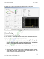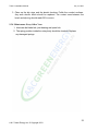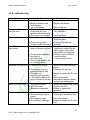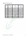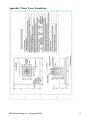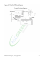
1
INSTALLATION MANUAL
Talon5 Grid-Tied
Featuring
Rev. 2.2.0
Talon 5 Installation Manual
July 14, 2010
Table of Contents
Contact information .........................................................................................................4
Statement ........................................................................................................................5
1. General........................................................................................................................6
1.1 Marking Illustrations ...........................................................................................6
2. Wind Generator Basics ...............................................................................................7
2.1 Grid-Tied Systems and Off-Grid Systems .............................................................7
2.2 Up wind Systems and Down Wind Systems..........................................................7
2.3 Fixed Pitch systems and Variable Pitch Systems..................................................7
3. TALON – The Downwind Variable Pitch System ........................................................8
3.1 Structure ................................................................................................................8
Fig. 13.2 Technical Specifications ...............................................................................8
3.2 Technical Specifications ........................................................................................9
3.3. Output Power and Performance Curves...............................................................9
3.4 Features...............................................................................................................10
3.4.1 Blades: ..........................................................................................................10
3.4.2 Generator: .....................................................................................................10
3.4.3 Variable Pitch Technology: ...........................................................................10
3.4.4 Other Features ..............................................................................................11
4. Safety Measurements ...............................................................................................11
5. Installation .................................................................................................................12
5.1 Preparation ..........................................................................................................12
5.2 Making the Foundation ........................................................................................12
5.3 Tower Assembly ..................................................................................................13
5.4 Generator Installation ..........................................................................................14
5.4.1 Generator Body Installation...........................................................................14
5.4.2 Blade Installation...........................................................................................15
5.4.3 Centrifugal Hammer Installation....................................................................15
5.4.4 Manual Shutdown System Installation ..........................................................16
5.4.5 Auto Shutdown System Installation (optional)...............................................18
5.5 Erecting the TALON.............................................................................................20
5.5.1 Inspection before Erecting the TALON .........................................................20
5.5.2 Erecting TALON with Crane..........................................................................21
5.5.3 Inspection of the Tower.................................................................................22
6. Electrical Wiring.........................................................................................................23
6.1 System Diagram ..................................................................................................23
6.2. Electronic Equipments Settings ..........................................................................23
6.3 Wiring Procedures ...............................................................................................24
7. Computer Monitoring System.................................................................................24
7.1 System Requirements .........................................................................................24
7.2 Features of the Monitoring System......................................................................24
7.3 Real Time Data Logging and Displaying .............................................................25
7.4 Screen Shots .......................................................................................................25
8. System Testing..........................................................................................................26
8.1 Inspection of the Electrical Wiring........................................................................26
8.2 System Testing ....................................................................................................27
2
A & C Green Energy Inc. © Copyright 2010
Talon 5 Installation Manual
July 14, 2010
8.2.1 Basic Testing.................................................................................................27
8.2.2 Advanced Testing .........................................................................................28
9. User’s Manual ...........................................................................................................29
9.1 How to Shutdown and Start the System ..............................................................29
9.1.1 Starting the System.......................................................................................29
9.1.2 Manual Shutdown .........................................................................................29
9.2 User Routine Check.............................................................................................30
9.3 Maintenance ........................................................................................................30
9.3.1 Maintenance after 3 Months..........................................................................30
9.3.2 Checking After Heavy Winds ........................................................................31
9.3.3 Maintenance Every Year...............................................................................31
9.3.4 Maintenance Every Other Year.....................................................................32
10. Troubleshooting.......................................................................................................33
Appendix 1 Bolt Torque (Nm)......................................................................................... A
Appendix 2 Mono Tower Foundation ............................................................................. B
Appendix 3 On-Grid Wiring Diagram.............................................................................. C
Appendix 4 Guide on Choosing the Electrical Cables.................................................... D
Limited Warranty Information ......................................................................................... E
Talon 5 Warranty Registration Card...............................................................................G
3
A & C Green Energy Inc. © Copyright 2010
Talon 5 Installation Manual
July 14, 2010
Prior to installation and operation, it is important that you
thoroughly read this manual to ensure proper installation and
safety.
Contact information
1108 Summit Ave., Suite 8
Plano, TX 75074
Tel: 866-WNDPWRD
Fax: 972-516-0697
Web: www.acgreenenergy.com
4
A & C Green Energy Inc. © Copyright 2010
Talon 5 Installation Manual
July 14, 2010
Statement
A&C Green Energy is not responsible for any damage and/or injury caused under the
following situations:
* Damage caused by any incorrect installation
* Damage caused by using unauthorized equipment
* Damage caused by any incorrect operation
* Damage caused by lightning, typhoon and other force majeure
Note:
1. The off-grid installation manual is available on line at www.acgreenenergy.com or
call A & C Green Energy, Inc.
2. To install the system correctly, sometimes a certified structural engineer and
licensed electrician is necessary.
3. The annual power output from the system is determined by the local wind
resources and some other factors, such as the installation elevation,
temperature, system conditions, terrain and density of periphery buildings.
5
A & C Green Energy Inc. © Copyright 2010
Talon 5 Installation Manual
July 14, 2010
1. General
1.1 Marking Illustrations
Each sign below has its special meanings. It is mandatory for the installers and users
to understand their meanings and act accordingly. Contact us if you need help.
Warning: means there are risks that may cause personal injury or even death.
Caution: means there are risks that may cause wind turbine, equipment or property
damage.
Advice: helpful installation & maintenance hints from the manufacturer.
6
A & C Green Energy Inc. © Copyright 2010
Talon 5 Installation Manual
July 14, 2010
2. Wind Generator Basics
2.1 Grid-Tied Systems and Off-Grid Systems
•
Off-grid application: The electricity generated by the wind turbine can be stored
into batteries. Through an off-grid inverter, the DC electricity can be changed
into stable AC electricity for off-grid power supply.
•
On-grid application: The electricity generated by the wind turbine can be
rectified into DC electricity. Through an on-grid inverter, the DC can be
converted into stable AC and feed the local utility grid.
2.2 Up wind Systems and Down Wind Systems
The terms Upwind and Downwind refer to the relation of the turbine blades to the
pole. An upwind turbine orients the blades on the upwind side of the pole and
vice-versa. An upwind turbine can have a tail or no tail. A downwind system has no
tail. The blades naturally maintain their orientation on the downwind side of the pole no
matter which direction the wind blows.
2.3 Fixed Pitch systems and Variable Pitch Systems
•
What is Variable Pitch Technology? This is an advanced method of regulating
the rotor RPM by adjusting the blade’s attack angles based on the RPM. When
the RPM goes higher, the attack angle will decrease so the rotor slows down.
This system enables the wind turbine to maintain a constant peak output during
times of high wind.
•
How does TALON Variable Pitch Technology work? The principle is using
centrifugal force to make the blade rotate along its axis. Each of the Talon's 3
blades has an attached centrifugal hammer which acts when the generator
reaches the rated RPM and causes the blade to rotate along its axis to reduce
the attack angle. .
•
Why is Variable Pitch Technology important? The variable pitch system
produces more energy than other systems simply because it will not shut down
when the rated wind speed is reached as other wind turbines do. When the wind
speed reaches 25mph, other systems begin to shut down. However, a variable
pitch system keeps generating energy at the peak rate. This makes a significant
difference in the total power generated.
•
What does all this mean? With the increased power output from the Talon
wind turbine, you will have more energy to use and more energy bill savings.
The better technology means a higher return on your investment.
7
A & C Green Energy Inc. © Copyright 2010
Talon 5 Installation Manual
July 14, 2010
3. TALON – The Downwind Variable Pitch System
3.1 Structure
The completely installed turbine is composed of variable pitch blades, permanent
magnet generator (PMG), slip ring, tower, braking system, E-Load Box, inverter, etc.
Fig. 1
8
A & C Green Energy Inc. © Copyright 2010
Talon 5 Installation Manual
July 14, 2010
3.2 Technical Specifications
TECHNICAL SPECIFICATIONS
Blade Diameter
Blade Material/Quantity
Rated Power
Maximum Power
Rated Wind Speed
Start-Up Wind
Working speed
Survival Wind
Rated rpm
Generator Type
Speed Regulation
Shut Down Method
Generator Lifespan
18.37 feet
FRP/3
5,000 W
5,400 W
24.6 mph
6.7 mph
9-56 mph
112 mph
240
3 phase AC PMG
Variable Pitch
Manual or Auto Shutdown
15 years
Table 1
3.3. Output Power and Performance Curves
Wind Speed (m/s)
Wind Speed
(mph)
Output Power
(W)
kWh / Month
4
5
6
7
8
9
10
11
12
13
14
15
16
9
11
13
15
18
20
22
24
27
29
31
33
36
200
450
1250
1450
2130
3030
4120
5400
146
329
914
1059
1556
2213
3010
3945
9
A & C Green Energy Inc. © Copyright 2010
Talon 5 Installation Manual
July 14, 2010
3.4 Features
3.4.1 Blades:
With a high tip-speed ratio and a noise lower than 65db, the blades have been
aerodynamically optimized for better performance. The blades have passed extensive
wind tunnel tests. The co-efficiency of the blades is over 0.4.
Made of the same material as the mega-watt wind generator systems, the special
purpose gel-coat resin and reinforced FRP, each Talon blade set is highly durable and
will guarantee safe operation under a wind speed of up to 56mph wind speed.
3.4.2 Generator:
Features rare earth magnets, high temperature, enamel-coated magnet wire and top
grade bearings, which make the generator’s efficiency greater than 90%. The
generator reaches F-Grade insulation and IP54 protection standard, and is designed
as maintenance free during its life time. The cast steel housing is galvanized and
powder coated for long lasting life and harsh environment.
3.4.3 Variable Pitch Technology:
All wind systems adopt some type of speed regulation method to avoid self-destruction.
The megawatt systems pitch their blades to maximize the power output using
automatic control systems. Most small wind systems use either tail furling or an
electronic brake to control the RPM. However, both of these methods will significantly
reduce the power output since they shut down the system at its rated RPM. The
electronic brake may also cause the generator and electronics to burn out during
extended high winds.
TALON systems use centrifugal force to adjust the pitch angle of the three blades to
regulate the RPM. It is a self adaptive process. When the rotor is static, the pitch angle
is about 10 degrees. As the RPMs go higher, the centrifugal force becomes greater
and starts to push the blades to reduce the pitch angle to slow down the rotor. On the
contrary, when the wind slows down, the pitch angle increases to help raise the RPM.
At about the rated wind speed, the system will reach a balance so the RPM begins to
wave around the rated value until wind speed reaches 56mph. Therefore, the power
generated will be significantly higher than the other speed regulation methods since the
working range is much larger.
Fig. 2 shows how this passive centrifugal variable pitch technology works.
10
A & C Green Energy Inc. © Copyright 2010
Talon 5 Installation Manual
July 14, 2010
Fig. 2
When the wind speed is below 7 mph, the turbine blade angle remains static and the
angle (X1) formed between the blade and turbine plane is B° (X1=B°). This is the ideal
angle for the blades to begin their rotation. As long as the wind speed reaches 7 mph,
the blades will begin to rotate. While rotating, the outermost edge of the blade will be
driven by the centrifugal force generated by the rotation of the blade to tilt toward the
turbine plane. As the wind speed increases, the blade angle (X1) will then decrease to
0° so that the blade is parallel with the turbine plane. At this angle, the turbine has
nearly reached its rated output power. When the wind speed is between 20 mph - 55
mph, the blade angle (X1) will stay near 0° with slight fluctuations in order to maintain
its rated power. When the wind speed is between 55 mph - 112 mph, the wind will draw
the blade by the centrifugal force, so the angle (X1) will continue to decrease to a
negative angle (X1 = -B°) [B° and -B° are not the same]. Under this negative angle, the
blade angle will produce a resistance on the rotation of turbine blades to slow down the
turbine, thus protecting it from over-speed operation. The maximum revolution of the
turbine will be no more than 300 RPM.
3.4.4 Other Features
The TALON adopts a downwind system design, which eliminates the tail. All the parts
are galvanized and powder coated so they can last for years without rusting.
4. Safety Measurements
1. Do not allow the TALON to run without a load. A no-load condition may cause
damage to generator itself or the blades.
2. Avoid allowing the system to run under high wind speed (>= 56mph) for an
extended period of time. It is recommended (though not required) to shut down
the wind turbine manually when the wind speed is over 56mph to protect the
wind generator.
11
A & C Green Energy Inc. © Copyright 2010
Talon 5 Installation Manual
July 14, 2010
3. Do not flip the switch on the E-Load Box to Manual Brake when the RPM is
high. Only do it after the brake is manually applied so that the rotor slows down
or does not spin.
4. Before disconnecting the E-Load Box from the generator, set the brake
manually by pulling down and locking in the winch (lever). After disconnecting
the E-Load box from the generator, short circuit the 3 wires from the generator.
5. Do not stand under running wind turbines during high winds.
6. If there is an unprecedented vibration or strange noise being detected during the
turbine operation, stop TALON immediately for inspection.
7. When setting up the TALON, be sure to set the brake and that the 3 wires from
the generator are short circuited until all the electronics are connected. When
disassembling the TALON, please put the generator on brake and short circuit
the 3 wires from the generator, then disconnect the electronics. (See appendix
3)
8. All electrical connections should strictly follow the NEC code. All electrical
equipment and the generator pole need to be properly grounded according to
NEC code.
5. Installation
5.1 Preparation
1. Check the parts against the packing list. If you encounter any packaging
discrepancies, contact your Talon reseller immediately.
2. Keep all the parts and components away from water.
3. Prepare electrical cables based on the table in Appendix 4. Since the transport
loss of AC is greater than DC’s, we recommend the E-Load Box be installed
within 660 feet from the generator. If the distance is greater, please choose a
thicker wire based on the table in Appendix 4.
4. The turbine should be installed when the wind speed is less than 18 mph.
5.2 Making the Foundation
Notes: the foundation varies based on the soil conditions and location. The technical
12
A & C Green Energy Inc. © Copyright 2010
Talon 5 Installation Manual
July 14, 2010
drawing in Appendix 2 only applies to an 8 meter tower on the soil conditions specified
and a non-flooded area. Please contact A&C Green Energy, Inc for availability of
technical drawings for your location or consult a local certified structural engineering
firm for the appropriate foundation design.
1. Dig a 9’!9’ square hole that is 4’ deep
2. Make a rebar grid as shown in appendix 2. The quality of this grid is crucial to
the strength of the tower base. Fix the bottom and top positioning plates onto
the grid. Set the 12 anchor bolts through the 12 holes of the bottom and top
positioning plates. Adjust the alignment to make sure the 12 anchor bolts are
perpendicular to the positioning plates.
3. Put a 4” layer of concrete at the bottom of the hole and make it level.
4. Make a frame with inner dimensions of 9’X9’ using two layers of wood boards.
Place the frame around the pit and set the rebar grid in the center of the pit.
Make sure the positioning plates are level.
5. Make a 90 degree
should be at the
projected concrete
and be connected
duct tape.
conduit and fix it onto the rebar grid. One end of the conduit
center of the top positioning plate with 0.5-1” above the
surface. The other end should come out of the side of the pit
to the conduit in the ditch. Cover the conduit opening with
6. Pour the concrete.
7. Wait at least 100 hours to allow the concrete to cure. During this period do not
touch it or attempt to install the wind turbine.
8. After the concrete has cured, remove the wood frame and fill the side of the
concrete with soil and stone. Tamp it tight.
5.3 Tower Assembly
13
A & C Green Energy Inc. © Copyright 2010
Talon 5 Installation Manual
July 14, 2010
1. Bolt the upper and lower tower sections together. Make sure the markings on
the tower sections are aligned.
2. Place the connected tower with the tower bottom close to the foundation; put a
bracket beneath the tower 1 " feet away from the tower top.
3. Using a steel wire, insert the electrical cable (3 leads) and the steel cable into
the tower top and pull them out from bottom of the tower. Leave 18 inches
outside the tower top.
5.4 Generator Installation
5.4.1 Generator Body Installation
1. Fix the patch board onto the top end of the tower. Connect the 3 leads of the
electrical cable inside the tower onto the terminals on one side of the patch
board. Connect the three leads of the electrical cable from the turbine to the 3
terminals on the other side of the patch board respectively. Short circuit the 3
leads of the electrical cable so the generator will not spin during the installation.
2. Bolt the vibration isolator onto the tower top by aligning the flange holes of the
vibration isolator with the flange hole of the tower top. Tighten the 8 M16!60
inner hexagonal bolts (including the spring washer and flat washer).
3. Lift the wind turbine to align the bottom flange with the vibration isolator flange,
bolt them up with eight M16!60 outer hexagonal bolts.
14
A & C Green Energy Inc. © Copyright 2010
Talon 5 Installation Manual
July 14, 2010
Fig.2
Fig.3
5.4.2 Blade Installation
1. Lift the generator body, which has been connected to the tower with the hub
facing sides or down. (Fig 4 and Fig 5)
2. Fix the three blades onto the hub with 12 M16X110 hexagon bolts. Please make
sure the letters on the blades match the letters on the hub. Be sure to use flat
washers, lock washers and nuts. The torque of the bolts must be 180~210Nm.
Short circuit the 3 leads of the electrical cables to prevent the rotor from
spinning.
5.4.3 Centrifugal Hammer Installation
Hold the centrifugal hammer downward and fix it onto the blade hub one by one.
Please refer to Fig. 8 for the correct positioning of the hammers. The four M12!20
hexagon bolts and spring washers are to be used for each hammer (Fig. 6, Fig. 7
and Fig. 8).
15
A & C Green Energy Inc. © Copyright 2010
Talon 5 Installation Manual
July 14, 2010
The inappropriate installation of the centrifugal hammers will cause variable
pitch failure, which will damage the system and may cause personal injuries.
5.4.4 Manual Shutdown System Installation
The mechanism of shutting down the TALON wind generator is implemented by
adjusting the blade pitch angle so that the rotor loses propelling power from the wind.
The manual shutdown system includes a winch, the steel cable and the variable pitch
blades. When the winch is applied, the cable pulls the blades to rotate along their axis
to have a smaller attack angle so the rotor stops. When the winch is released, the
spring pushes the blades back to their original orientation so the rotor can start
rotating.
5.4.4.1 Installation
Install the winch at the tower bottom with the provided bolts. Connect it with the steel
cable from the turbine body. (Fig. 9 and Fig. 10)
16
A & C Green Energy Inc. © Copyright 2010
Talon 5 Installation Manual
July 14, 2010
When installing the winch, adjust the cable tightness so that when it’s applied, the
blades will pitch to the largest angle allowed.
5.4.4.1 Inspection of the Blade Pitch and Braking Mechanism
The purpose of this step is to verify the blade pitch can be adjusted when the winch is
tightened so the turbine will stop rotating, and when the winch is released, the blades
return to the normal pitch angle so the rotor spins.
1. Check the tightness of the steel cable. When the winch is not applied, the steel
cable is loose and the blades pitched at about B=10 degrees to catch the wind.
When the winch is applied, the steel cable is tightened up and the blade pitch
becomes B=-7 to -8 degrees with the rotation plane. See Fig. 2.
2. Manually tighten up and release the steel cable 2 or 3 times, verify the blade
pitch angle changes accordingly. Make sure the winch can be held at the stop
position with the positioning bolt.
This step should be completed before the tower is erected.
17
A & C Green Energy Inc. © Copyright 2010
Talon 5 Installation Manual
July 14, 2010
5.4.5 Auto Shutdown System Installation (optional)
The automatic shutdown system adds an electric activator to the manual shutdown
system to pull the steel cable instead of using a manual winch.
5.4.5.1 The System Components
The auto braking system includes a braking controller, which is powered by a 12V
rechargeable battery, an electric pushing rod, E-Load Box and a battery charger.
The braking controller (top left corner of Fig 11) has two meters on its panel. One
meter shows the grid voltage and the other shows the battery voltage. There is also a
start button and a stop button on the same panel which is used to start the system or
stop the system manually by activating and deactivating the pushing rod.
The pushing rod is connected to the brake controller. Whenever the grid is down, the
brake controller will activate the pushing rod to shut down the turbine. When the grid
comes back, the brake controller will activate the pushing rod in the reverse direction to
restart the turbine.
The E-Load Box is connected to the brake controller and provides the shutdown signal
whenever the voltage reaches the threshold or the dump load is too hot.
The charge controller guarantees the battery is always fully charged.
Fig. 11
4.5.5.2 System Functions
18
A & C Green Energy Inc. © Copyright 2010
Talon 5 Installation Manual
July 14, 2010
The system shuts down in the following conditions:
1. Auto Shutdown for High Wind: when the wind speed is too high and the
generated voltage reaches the threshold, the E-Load Box will send out a
signal to the brake controller. The brake controller activates the electric
pushing rod so the steel cable is pulled to force the blade pitch to stop.
2. Auto Shutdown When Grid Down: when the grid is down. The brake
controller activates the pushing rod to pull the steel cable to stop the
generator. When the grid has recovered, the brake controller sends a restart
signal to activate the pushing rod to release the cable so the generator starts
rotating.
3. Manual Shutdown: to provide a way to shutdown the system when the auto
shutdown system fails, the steel cable can be pulled via the manual braking
knob at the bottom of the bracket (Fig 11B). To restart the system, manually
loose the knob so the blades restore their original orientation to start rotate.
4. Manual Start: after the system is shutdown automatically because of high
wind, the system has to be restarted manually for safety reasons. To start,
push down the start button on the controller and hold it until the pushing rod
releases the steel cable. The blades restore to the initial pitch angle and start
rotating under the wind.
5.4.5.3 Installation
The electric pushing rod is already installed in the tower. The braking controller, battery
and the battery charger need to be installed in a covered area with the E-Load Box.
Connect the steel cable from the generator to the pushing rod so when the pushing rod
is activated, the cable will be pulled.
Use electric wire to connect the braking control box with the battery, grid, electric
pushing rod and E-Load box as the Fig. 11 shows. Connect the battery to the braking
control box. The gauge 15 or thicker wire should be used. Make sure the polarities are
correct when connecting.
19
A & C Green Energy Inc. © Copyright 2010
Talon 5 Installation Manual
July 14, 2010
Fig. 11B
5.5 Erecting the TALON
5.5.1 Inspection before Erecting the TALON
The inspection is an ongoing process which should be done during the installation to
make sure each part is installed correctly and securely. Before erecting the tower,
inspect all the parts installed on the top of the tower. The following is a list of items to
be checked:
1. Check to make sure the blades are fastened securely to the hub. Make sure all
the nuts are tightened up with the right torque. Make sure the distances between
the blade tips are equal.
2. Check to make sure the centrifugal hammers are securely installed. Make sure
all the nuts are tightened up with the right torque. Verify with Fig. 8 to make sure
the direction of the hammers is correct.
3. Verify the initial attacking angle is about 10 degrees and the stopping angle is
20
A & C Green Energy Inc. © Copyright 2010
Talon 5 Installation Manual
July 14, 2010
about -7 to -8 degrees. When the winch is not applied, the steel cable should
be loose and the blades will pitch about B=10 degrees to catch the wind. When
the winch is applied, the steel cable is tightened up and the blade pitch becomes
B=-7 to -8 degrees in relation to the rotation plane. See Fig. 2.
4. Manually apply the winch 2 to 3 times. Verify the blade pitch angle changes
accordingly. Make sure the winch can be held at the stop position with the
positioning bolt. Apply the winch at the end of the testing.
5. With the 3 output wires open, turn the rotor manually to make sure the generator
can rotate freely. Be sure to short circuit the three wires after this testing.
Steps 3 and 4 are very important and must be performed precisely. The purpose
is to test if the blade pitch can be adjusted when the winch is applied so the
turbine will stop rotation; and when the winch is released, the blades return to
the normal pitch angle so the turbine spins.
These testing steps should be completed before the tower is erected.
5.5.2 Erecting TALON with Crane
1. Put 12 nuts onto the 12 anchor bolts before lifting the tower. Screw these nuts
down to leave enough space for the tower flange. The washers and nuts will be
on top of the flange. (Fig. 13)
2. Securely wrap a strong and flexible textile belt to the generator and lift it up with
a crane. When the tower base leaves the ground, align it to the anchor bolts
so the tower flange will fit into the 8 anchor bolts. Put on the flat washers and
lock washers on the anchor bolts and screw the nuts onto the anchor bolts
loosely. (Fig 12, Fig. 13 and Fig. 14)
3. Choose two pair of anchor bolts which form a cross. Loose all the nuts on the
other anchor bolts both on top of flange and beneath the flange. Adjust the four
nuts beneath the flange to make the tower level then tighten up both the upper
and lower nuts simultaneously. After the tower is leveled, tighten up all the other
nuts in the diagonal order. (See Figs 12,13,14)
21
A & C Green Energy Inc. © Copyright 2010
Talon 5 Installation Manual
July 14, 2010
Fig. 12
Fig.14
Fig. 13
Make sure the winch is applied and the 3 wires are short circuited during the
installation.
When the tower is lifted and about to leave the ground, the tower may swing and
hit the base or anchor bolts. To prevent damage, position the crane so that the
tower base has enough clearance from the base when it’s lifted.
When the tower is lifted above the ground, the generator and tower may rotate
horizontally and cause the blades to hit the crane arm. Please make sure the
crane arm has enough clearance from the generator blades or have a person
hold on the pole so it will not spin.
5.5.3 Inspection of the Tower
1. After the tower is erected, make sure all the nuts are tightened up to the torque
specified.
2. Observe the generator to make sure it can rotate horizontally with the changes of
the wind direction. If there is no wind, climb up to the tower and manually rotate
the generator to test if the generator stops at random spot. If the generator
always stops at the same position, please readjust the nuts to make the tower
straight and continue testing until the tower is level.
22
A & C Green Energy Inc. © Copyright 2010
Talon 5 Installation Manual
July 14, 2010
6. Electrical Wiring
6.1 System Diagram
Fig. 16
The diagram for the grid-tied turbine system is shown in Fig. 16. The corresponding
wiring diagram is showed in appendix 3. The system consists of the wind turbine,
E-load box (with dump load inside), UL1741 compliant grid-tied inverter and the
grid. The wild AC generated by turbine is converted to DC by E-Load box, which in
turn is fed into the inverter. The inverter synchronizes itself with the grid and puts
out the AC power with the same voltage and cycles as the grid. The generated
electricity is automatically consumed by the appliances or makes the utility meter go
backward.
6.2. Electronic Equipments Settings
To have proper ventilation and easy connection of the cables, please refer to the
manuals for proper clearance around the electronic equipments.
For the E-Load box settings, please keep 8 inch clearance on the top, and 8 inch
clearance on the right. 4 inch on the left and bottom.
For the inverter settings, please keep 6 inch clearance on top and right sides, 8 inch
clearance below and 2 inch clearance on the left. Refer to page 19 of the installation
manual for details.
23
A & C Green Energy Inc. © Copyright 2010
Talon 5 Installation Manual
July 14, 2010
6.3 Wiring Procedures
1. Refer to the E-Load and inverter manuals to connect the E-Load and inverter
together.
2. Set the brake on the side of the E-Load box to manual brake, and connect the 3
wires of the wind generator to the E-Load box. This brake actually short circuits
the 3 wires of the generator together.
3. The dump load is already installed in the E-Load.
4. The output of the E-Load should be connected to the DC input of the inverter via
a fuse or a breaker suggested by the inverter. Make sure the polarity is
connected correctly when making this connection.
5. Refer to the inverter manual to connect the inverter with the grid. Make sure the
connection meets the grid voltage.
6. Ground the electronic equipments and tower according to the NEC code.
Please refer to the E-Load box and inverter manual to choose the right circuit
breakers and fuses.
7. Computer Monitoring System
A computer can be hooked up with the inverter to pull the real time data out of the
inverter and display it on the screen. It can also pull the history data for analysis. The
monitoring software is free and comes with the inverter. User needs to provide his own
computer.
7.1 System Requirements
The monitoring software needs to run on a windows based computer system with a
USB connection. These are minimum hardware requirements:
CPU: 2GHz
RAM: 512 MB
USB Port
Operating System: Windows 2000, Windows XP or Windows Vista
7.2 Features of the Monitoring System
1.Multiple language support. You can choose to use English, Spanish, French,
Italian and German.
2.Multiple inverter support. One computer can monitor multiple inverters.
24
A & C Green Energy Inc. © Copyright 2010
Talon 5 Installation Manual
July 14, 2010
3.Warning and Error Logs.
4.Configurable sampling time interval.
5.Date / Time Synchronization between computer and inverters.
7.3 Real Time Data Logging and Displaying
The system collects and displays the energy harvested and the system status. The
data can be displayed in multiple ways. You can choose to
1. Show the real time voltage and power output of each inverter.
2. Show the real time power and energy generated.
3. Show the statistics as bar chart using the history data by days, weeks, months,
years and life span
4. Review and download alarms and warnings reported by inverter
7.4 Screen Shots
The screen shot in Fig. 17 shows the real time power and the energy generated by the
system.
Fig. 17
25
A & C Green Energy Inc. © Copyright 2010
Talon 5 Installation Manual
July 14, 2010
The screen shot of Fig. 18 is the output power and the status of the system.
Fig. 18
8. System Testing
8.1 Inspection of the Electrical Wiring
It’s very important to perform an inspection before starting the system testing since
mistakes may cause equipment damage or personal injury.
1. Check the E-Load box to make sure it is connected correctly. The 3 wires of the
generator outputs should connect to the wind inputs of the E-Load box. The DC
outputs of the E-Load box are connected to the inverter’s inputs. Make sure the
polarity is connected correctly between the E-Load and inverter.
2. Make sure the DC breaker and fuse are installed to the specs of the inverter
manual.
3. Check the output connection of the inverter to make sure it produces the same
voltage as the grid power. Please contact A&C Green Energy Inc. for tech
support or consult a licensed electrician for help.
26
A & C Green Energy Inc. © Copyright 2010
Talon 5 Installation Manual
July 14, 2010
4. Check if the system is grounded properly. Use the NEC code for the grounding
specification. Make sure the controller, inverter and the generator tower are all
grounded.
8.2 System Testing
Since the wind speed may not be strong enough to test all the cases, we divide the
system testing into two parts, the basic testing and advanced testing. The basic testing
is mandatory before putting the system in the production. The advanced testing can be
done whenever the wind speed is available.
8.2.1 Basic Testing
To perform the following basic tests, you need to have at least 10mph wind speed.
1. The turbine should be static before this test.
2. Start the turbine by flip the manual brake to Normal Running on the side of the
E-Load Box so to connect the generator to the E-Load Box. Manually release
the winch so the generator can start.
The turbine starts to rotate when the wind speed reaches 5.6 mph. The starting
wind speed is slightly higher during the first several startups. But it will become
normal after the break in period.
Set the multi-meter to AC mode and check to verify the line-line AC voltages of
the 3 output leads of the generator are identical. Change the multi-meter to DC
mode and check to observe if the output DC voltage of the controller increases
when the rotor speeds up. When the DC voltage reaches about 202 volts at
about 10 mph wind speed the inverter should start working, the LED should light
up, and the power should start to feed into the grid.
3. With the generator rotating, manually apply the winch and observe if the
generator gradually stops and starts when the winch is released.
4. If the auto shutdown system is installed, press the stop button on the control box
to verify the rotor stops gradually. Press and hold the start button to verify the
rotor starts to spin.
5. Manually turn the braking knob at the bottom of the bracket counter clockwise to
pull the steel cable to stop the rotor and turn it clockwise to see if the rotor starts
to spin.
6. Cut off the grid power and verify the inverter stops putting out electricity (UL
27
A & C Green Energy Inc. © Copyright 2010
Talon 5 Installation Manual
July 14, 2010
1741 compliance). If the auto shutdown system is installed, verify the pushing
rod starts to pull the steel cable and generator gradually stops.
7. If any of the above testing fails, stop the generator by applying winch and go to
the trouble shooting procedures.
8. If the turbine has passed the above testing, it is ready for production.
8.2.2 Advanced Testing
Advanced testing is not mandatory, but we recommend it be done whenever the wind
resource is available. In case it cannot be performed right away, we advise the user to
observe the system behavior whenever a high wind situation happens and
communicate with the installer about the system behavior and report any abnormal
situations.
To perform this test, you need to have over 23mph wind speed.
1. When the wind speed reaches 23mph, the blade pitch begins to change. This can
be observed using a pair of binoculars or by monitoring the line-line AC voltage.
The voltage should begin to stabilize instead of keeping going up.
2. When the wind speed reaches 56mph, the auto shutdown system starts to kick in
and the wind generator stops. When this happens, you have to manually restart
the generator using the start button on the controller.
3. Check the output power by multiplying the voltage and current. The peak output
power of the E-Load box should not exceed 5.8 KW. The E-Load’s output power
can be obtained by multiplying the DC voltage and the current of E-Load’s output.
28
A & C Green Energy Inc. © Copyright 2010
Talon 5 Installation Manual
July 14, 2010
9. User’s Manual
The TALON turbine system should be put into service ONLY after it has passed the
basic testing in the installation manual. The TALON turbine should be serviced ONLY
by authorized personnel. Call A&C Green Energy Inc or your TALON reseller should
you need assistance.
9.1 How to Shutdown and Start the System
9.1.1 Starting the System
No matter if it’s the first time you start the system or following a system shutdown,
always start the system in to the following order: Inverter>E-Load Box> Generator.
1. If this is the first time the system is to be started, make sure all the equipment
is connected correctly. Make sure the inverter is connected to both the grid
and the E-Load. Flip the electromagnetic brake to Normal Working position
on the side of the E-Load box and then release the winch to start the
generator.
2.If the system was shut down for maintenance, please make sure the
maintenance is complete and all the connections are restored correctly. Flip
the electromagnetic brake to Normal Working position on the side of the
E-Load box and then release the winch to start the generator.
3. If the system was shutdown automatically because of the grid is down, the
system will start automatically when the grid comes back.
4. If the system was shutdown because of high wind, please make sure the high
wind situation is over. Press the start button on the auto controller for 20
seconds to restart the system.
9.1.2 Manual Shutdown
For maintenance purpose or avoiding high wind damage to the system, the
turbine should be shut down manually.
1. If auto shutdown system is not installed, apply the winch manually to stop the
generator. After the winch is applied, the pitch angle of the turbine blade
becomes negative and rotor stops.
2. If the auto shutdown system is installed, press the stop button on the
controller for 20 seconds. Observe that the rotor slows down until RPM is
lower than 5. If the system fails to stop, turn the manual stopping knob to
29
A & C Green Energy Inc. © Copyright 2010
Talon 5 Installation Manual
July 14, 2010
manual stop the system.
3. In case the above shutdown procedures fail, manually flip the
electromagnetic brak on the side of the E-Load box to Manual Brake
position. This should be used only when the rotor spins slowly or as an
emergency stop.
Whenever there is a need to turn off any equipment along the power chain: the
generator, the E-Load and the inverter, always turn off the generator first, then
the E-Load and then the inverter. But whenever it’s ready to be started, do it in
the reverse order, i.e. start the inverter first, then E-Load and then generator.
9.2 User Routine Check
The following routine check can be done by the users each week.
1. If there is abnormal vibration or noise, shut down the turbine for further
inspections.
2. Check if the blade pitch changes smoothly when the wind speed is over the
rated speed.
3. If the generator does not go with the wind direction, the tower level needs to be
adjusted.
4. Observe the blades with a pair of binoculars for any damages which may cause
the system out of balance. Also check if the blades need to be cleaned because
of dirt or bugs, which may reduce system efficiency.
5. Check and Make sure the dumping load of the E-Load Box works well when the
wind speed approaches the rated wind speed.
6. If the auto shutdown system is installed, make sure the battery is fully charged.
9.3 Maintenance
9.3.1 Maintenance after 3 Months
1. Check all nuts and bolts, and tighten them up in accordance to the torque
defined in Appendix 1. Check the tightness of the following bots and nuts:
•
The tower foundation and the anchor bolts and nuts
•
The bolts and nuts which connect the towers together
•
The bolts and nuts which connect the generator to the tower
30
A & C Green Energy Inc. © Copyright 2010
Talon 5 Installation Manual
•
The Rotor hub nuts
•
The Blade bolts and nuts
•
The Bolts between the generator and nacelle
•
The round nut on the vertical shaft bearing
July 14, 2010
2. Check the welding of the tower rod to ensure that there are no cracks of flaws.
Checking emphasis is as follows:
• root part
•
connection flanges
•
tower top flange
•
rotor hub
3. Check the steel cable. Replace if damaged.
4. Check the Generator Output Cable
•
Check to see if the three power output cables are firmly fixed inside the
nacelle, or if the sheath has been damaged.
•
Check if the 3 wires have been connected firmly with the brushes and
they have a good electric contact.
•
Check if the electric brushes have a good contact with the slip rings.
Observe if there is any over heat damage.
•
Check if the three phase voltages of the generator output are balanced.
5. Clean and Lubricate the Motion Mechanical Parts
• Open the nacelle window, cleaning the spine shaft and lubricate it.
• Open the nose cone, cleaning the joint bearing and lubricate it.
9.3.2 Checking After Heavy Winds
After strong wind (>56mph), repeat those checks in 9.3.1 and 9.3.2 again.
9.3.3 Maintenance Every Year
We recommend this to be done each year before wind season.
1. Repeat every check and maintenance process detailed in section 9.3.1-9.3.2.
2. Check the conditions of the rotor.
• Checking the contour of the blades, especially the tips and front edges, to
see whether there are any cracks, damages or sign of unusual wear.
Check to see if unbalance or pitch angle inconsistence between the 3
blades.
31
A & C Green Energy Inc. © Copyright 2010
Talon 5 Installation Manual
July 14, 2010
3. Clean up the slip rings and the electric brushes. Polish the conduct surfaces.
Any worn electric brush should be replaced. The contact area between the
brush and slip ring should reach 95% or more.
9.3.4 Maintenance Every Other Year
1. Lubricate the blade hub, joint bearing and spine hub.
2. The spring position inside the rotary body should be checked. Replace
any damaged springs.
32
A & C Green Energy Inc. © Copyright 2010
Talon 5 Installation Manual
July 14, 2010
10. Troubleshooting
Problem
Excess Vibration
Turbine head does not
track the wind
Possible Reasons
1. Blade bolts are loose
2. Blade is defective and
out of balance
3. Ice on the blades
1. There is too much oil
sludge and dirt in the
vertical shaft and bearing
2. The tower is not straight
1. Parts are loose
Possible Solutions
1. Tighten up the bolts
2. Replace the blades
3. Remove the ice
1. Clean up and remove the
dirt, lubricate it.
2. Level the tower
Abnormal Noises
1. Lower turbine and tighten up
the loose parts.
2. Rotor moving part is
2. Find and eliminate the
interfering with other parts
problem
Rotor RPM is slower
1. Variable pitch system
1. Check the variable pitch
than normal
does not function properly
mechanism make sure the
pitch angle is correct and
lubricate the moving parts.
2. The generator winding or 2. Test the remove the short
the output is
circuit situation.
short-circuited
3. Flip the switch to Run
3. The E-Load switch is set
on to Manual Brake
Generator voltage is low 1. Rotor RPM is too low
1. Refer to the touble shooting
above
2. The slip ring does not
2. Clean up the slip rings
conduct electricity well.
3. E-Load box is
3. Repair or replace the E-Load
short-circuited internally.
box.
4. The electric cable is too 4. Reduce the power
long or the wire is too thin
transmission distance and/or
increase the cable gauge
There is no AC current
1. AC breaker is open
1. Locate the breaker and close it
2. AC Fuse blown
2. Replace the fuse
3. Generator is damaged
3. Repair or replace the
generator
There is no DC current
1. DC fuse blown
1. Replace the fuse
2. The transmission line is
2. Repair the transmission line
broken
3. DC breaker is open
3. Close the breaker
4. E-Load Box is damaged
4. Repair or replace the E-Load
Box
33
A & C Green Energy Inc. © Copyright 2010
Appendix 1 Bolt Torque (Nm)
Grade
35 45 HB101
207 5.6
#s
40Cr 40MnB
16MnVB 45 HB285
321 8.8
HRC35 40 10.9
#s 640MPa
#s 800MPa
300MPa
M6
4 6.5
6 12
M8
8 15
16 30
M10
18 30
36 63
M12
30 47
70 110
90 135
M16
85 127
180 210
220 300
M20
167 250
350 410
440 520
M24
300 460
580 650
820 900
A&C Green Energy Inc., © Copyright 2010
A
Appendix 2 Mono Tower Foundation
A&C Green Energy Inc., © Copyright 2010
A
Appendix 3 On-Grid Wiring Diagram
A&C Green Energy Inc., © Copyright 2010
A
Appendix 4 Guide on Choosing the Electrical Cables
Distance between
Generator & E-Load
(D)
D <= 650’
650’ < D <= 1,600’
1,600’ < D <= 2,600’
Cross
Section Area
mm2
>=6
>=10
>=16
A&C Green Energy Inc., © Copyright 2010
Maximum
Current
(Amp)
24
40
64
USA
Gauge
(AWG)
8
5
3
Total
Length
3XD
A
Limited Warranty Information
A&C GREEN ENERGY 5 YEAR LIMITED WARRANTY
Talon wind turbines, electronics, and associated equipment manufactured by or for A&C
Green Energy, Inc. are warranted against defects in design, material, and workmanship,
under normal use for which intended, for five (5) years after delivery and as set forth below.
Warranty Fulfillment: A&C Green Energy agrees to be the liaison between the
manufacturer of the products sold and the Buyer. The Buyer will be responsible for
returning any defective product to A&C. A&C will be responsible for returning the warranty
replacement to the Buyer. If it is determined that the item returned was damaged due to a
non-warranted condition, Buyer will be responsible for any cost of repair and return
shipping.
Proper Registration: Your registration must be completed within 30 calendar days of
your dated receipt in order to validate this Limited Warranty. You may complete
registration
by
filling
out
the
online
registration
form
online
at
http://www.acgreennergy.com/registerwarranty or by completing the mail-in registration card
as stated on the A&C Green Energy Registration Form and mailing it to:
A&C Green Energy
P.O. Box 941122
Plano, TX 75094
Upon your registration you shall receive a confirmation via email to inform you that your
product has been properly registered. Both proper registration and a dated proof of
purchase are required prior to obtaining warranty service.
Instructions: To obtain warranty service, simply call (800) 963-7973.
When calling, please have all proof of purchase documentation and service material
available including all serial and part numbers to help us quickly assist you.
Repair/Replacement Warranty: This Limited Warranty shall apply to any repair,
replacement part or replacement product for the remainder of the original Limited Warranty
period or for Five (5) years whichever is longer. Any defective parts or product replaced
under this Limited Warranty will become the property of A&C Green Energy.
This limited warranty covers only the hardware components packaged with the Product. It
does not cover technical assistance for hardware or software usage and it does not cover
any software products whether or not contained in the Product; any such software is
provided “AS IS” unless expressly provided for in any enclosed software Limited Warranty.
Please refer to the End User License Agreements included with the product for your rights
and obligations with respect to the software.
This Limited Warranty only covers product issues caused by defects in material or
workmanship during ordinary consumer use. It does not cover product issues caused by
A&C Green Energy Inc., © Copyright 2010
A
any other reason or use. This includes but is not limited to acts of God, misuse, limitations
of technology, or modification of any part of the product. This Limited Warranty does not
cover products sold “AS-IS” or “WITH ALL FAULTS” or consumables (such as fuses or
batteries). This Limited Warranty is invalid if the factory-applied serial number has been
altered or removed from the product.
This limited warranty does not cover:
1) Towers, equipment, materials, or supplies not manufactured by/for A&C Green Energy;
2) A&C Green Energy equipment that has been modified or altered without prior factory
approval;
3) Damage or loss of function sustained during periods with wind speeds exceeding 50 m/s
(110 mph)
4) Repairs performed by other than authorized A&C Green Energy service personnel;
5) Acts of God; or
6) Incidental or consequential damages.
Pursuant to this Limited Warranty, A&C Green Energy, will, at its option (1) repair the
product using new or refurbished parts or (2) replace this product with a new or refurbished
product. For the purposes of this Limited Warranty “refurbished” means a product or part
that has been restored to its original specification. In the event of a defect the above
represents your exclusive remedies.
LIMITATIONS ON DAMAGES: A&C GREEN ENERGY SHALL NOT BE LIABLE FOR ANY
INCIDENTAL OR CONSEQUENTIAL DAMAGES FOR BREACH OF ANY EXPRESSED
OR IMPLIED WARRANTY ON THIS PRODUCT.
DURATION OF IMPLIED WARRANTIES: EXCEPT TO THE EXTENT PROHIBITED BY
APPLICABLE LAW, ANY IMPLIED WARRANTY OF MERCHANTABILITY OR FITNESS
FOR A PARTICULAR PURPOSE ON THIS PRODUCT IS LIMITED TO THE DURATION
OF THIS WARRANTY.
Mailing Address:
A&C Green Energy
PO Box 941122
Plano, TX 75094
Shipping Address:
A&C Green Energy
1108 Summit Ave., Ste 8
Plano, TX 75024
A&C Green Energy Inc., © Copyright 2010
A
Talon 5 Warranty Registration Card
Talon Model: _______Talon5
______________________
Serial Number: ____________________________________________
Where was this unit purchased?_______________________________
Purchase Date: ________________
Purchaser Information:
Name: ___________________________________________________
Address: _________________________________________________
City: ____________________
State: _________
Phone: ______________________
Zip: ___________
Email: _____________________
Keep this half for your personal records
------------------------------------------------------------------------------------
Talon Model: ___________ Talon5
______________________
Serial Number: ____________________________________________
Where was this unit purchased?_______________________________
Purchase Date: ________________
Purchaser Information:
Name: ___________________________________________________
Address: _________________________________________________
City: ____________________
State: _________
Phone: ______________________
Zip: ___________
Email: _____________________
Mail or fax this half to A&C Green Energy at fax# 972-516-0697
A&C Green Energy Inc., © Copyright 2010
A