1
ZigBee Cluster Library
User Guide
JN-UG-3077
Revision 2.1
6 February 2015
ZigBee Cluster Library
User Guide
2
© NXP Laboratories UK 2015
JN-UG-3077 v2.1
ZigBee Cluster Library
User Guide
Contents
About this Manual
23
Organisation
Conventions
Acronyms and Abbreviations
Related Documents
Support Resources
Trademarks
Chip Compatibility
23
25
25
26
26
26
26
Part I: General and Development Information
1. ZigBee Cluster Library (ZCL)
1.1 Member Clusters
1.2 Compile-time Options
30
34
2. ZCL Fundamentals and Features
2.1 Shared Device Structures
2.2 Accessing Attributes
2.2.1 Reading Attributes
2.2.1.1 Reading a Set of Attributes of a Remote Cluster
2.2.1.2 Reading All Attributes of a Remote Cluster
2.2.1.3 Reading an Attribute of a Local Cluster
2.2.2 Writing Attributes
2.2.2.1 Writing to Attributes of a Remote Cluster
2.2.2.2 Writing an Attribute Value to a Local Cluster
2.2.3 Attribute Discovery
2.2.4 Attribute Reporting
2.3 Default Responses
2.4 Bound Transmission Management
2.5 Command Discovery
2.5.1 Discovering Command Sets
2.5.2 Compile-time Options
3. Event Handling
35
35
37
37
37
39
40
40
40
43
44
45
46
46
48
48
49
51
3.1 Event Structure
3.2 Processing Events
3.3 Events
JN-UG-3077 v2.1
29
51
52
53
© NXP Laboratories UK 2015
3
Contents
4. Error Handling
59
4.1 Last Stack Error
4.2 Error/Command Status on Receiving Command
59
59
Part II: Clusters and Modules
5. Basic Cluster
5.1
5.2
5.3
5.4
63
Overview
Basic Cluster Structure and Attributes
Mandatory Attribute Settings
Functions
eCLD_BasicCreateBasic
69
5.5 Enumerations
71
5.5.1 teCLD_BAS_ClusterID
5.5.2 teCLD_BAS_PowerSource
5.5.3 teCLD_BAS_ApplicationProfileType
5.6 Compile-Time Options
6.1 Overview
6.2 Power Configuration Cluster Structure and Attributes
6.3 Functions
eCLD_PowerConfigurationCreatePowerConfiguration
6.4 Enumerations and Defines
6.4.1 teCLD_PWRCFG_AttributeId
6.4.2 teCLD_PWRCFG_BatterySize
6.4.3 Defines for Voltage Alarms
6.5 Compile-Time Options
75
76
86
87
89
89
91
91
97
Overview
Identify Cluster Structure and Attribute
Initialisation
Sending Commands
Starting and Stopping Identification Mode
Requesting Identification Effects (ZLL Only)
Inquiring about Identification Mode
Using EZ-mode Commissioning Features (HA only)
7.5 Sleeping Devices in Identification Mode
4
75
92
7. Identify Cluster
7.4.1
7.4.2
7.4.3
7.4.4
71
71
73
73
6. Power Configuration Cluster
7.1
7.2
7.3
7.4
63
64
68
68
© NXP Laboratories UK 2015
97
98
99
99
99
99
100
100
101
JN-UG-3077 v2.1
ZigBee Cluster Library
User Guide
7.6 Functions
101
eCLD_IdentifyCreateIdentify
eCLD_IdentifyCommandIdentifyRequestSend
eCLD_IdentifyCommandTriggerEffectSend
eCLD_IdentifyCommandIdentifyQueryRequestSend
eCLD_IdentifyEZModeInvokeCommandSend
eCLD_IdentifyUpdateCommissionStateCommandSend
7.7 Structures
7.7.1
7.7.2
7.7.3
7.7.4
114
Custom Data Structure
Custom Command Payloads
Custom Command Responses
EZ-mode Commissioning Command Payloads
7.8 Enumerations
7.9 Compile-Time Options
119
Overview
Groups Cluster Structure and Attribute
Initialisation
Sending Commands
8.4.1 Adding Endpoints to Groups
8.4.2 Removing Endpoints from Groups
8.4.3 Obtaining Information about Groups
8.5 Functions
119
119
120
120
120
120
121
121
eCLD_GroupsCreateGroups
eCLD_GroupsAdd
eCLD_GroupsCommandAddGroupRequestSend
eCLD_GroupsCommandViewGroupRequestSend
eCLD_GroupsCommandGetGroupMembershipRequestSend
eCLD_GroupsCommandRemoveGroupRequestSend
eCLD_GroupsCommandRemoveAllGroupsRequestSend
eCLD_GroupsCommandAddGroupIfIdentifyingRequestSend
8.6 Structures
122
124
125
127
129
131
133
135
137
Custom Data Structure
Group Table Entry
Custom Command Payloads
Custom Command Responses
8.7 Enumerations
137
137
138
139
140
8.7.1 teCLD_Groups_ClusterID
8.8 Compile-Time Options
JN-UG-3077 v2.1
116
116
8. Groups Cluster
8.6.1
8.6.2
8.6.3
8.6.4
114
114
114
115
116
7.8.1 teCLD_Identify_ClusterID
8.1
8.2
8.3
8.4
102
104
106
108
110
112
140
141
© NXP Laboratories UK 2015
5
Contents
9. Scenes Cluster
9.1
9.2
9.3
9.4
143
Overview
Scenes Cluster Structure and Attributes
Initialisation
Sending Remote Commands
9.4.1
9.4.2
9.4.3
9.4.4
9.4.5
Creating a Scene
Copying a Scene (ZLL Only)
Applying a Scene
Deleting a Scene
Obtaining Information about Scenes
9.5 Issuing Local Commands
9.5.1 Creating a Scene
9.5.2 Applying a Scene
145
146
146
146
147
147
147
147
9.6 Functions
148
eCLD_ScenesCreateScenes
eCLD_ScenesAdd
eCLD_ScenesStore
eCLD_ScenesRecall
eCLD_ScenesCommandAddSceneRequestSend
eCLD_ScenesCommandViewSceneRequestSend
eCLD_ScenesCommandRemoveSceneRequestSend
eCLD_ScenesCommandRemoveAllScenesRequestSend
eCLD_ScenesCommandStoreSceneRequestSend
eCLD_ScenesCommandRecallSceneRequestSend
eCLD_ScenesCommandGetSceneMembershipRequestSend
eCLD_ScenesCommandEnhancedAddSceneRequestSend
eCLD_ScenesCommandEnhancedViewSceneRequestSend
eCLD_ScenesCommandCopySceneSceneRequestSend
9.7 Structures
149
151
152
153
154
156
158
160
162
164
166
168
170
172
174
9.7.1 Custom Data Structure
9.7.2 Custom Command Payloads
9.7.3 Custom Command Responses
9.8 Enumerations
174
174
178
182
9.8.1 teCLD_Scenes_ClusterID
9.9 Compile-Time Options
182
182
10. On/Off Cluster
185
10.1 Overview
10.2 On/Off Cluster Structure and Attribute
10.3 Initialisation
6
143
144
144
145
© NXP Laboratories UK 2015
185
186
188
JN-UG-3077 v2.1
ZigBee Cluster Library
User Guide
10.4 Sending Commands
188
10.4.1 Switching On and Off
10.4.1.1 Timeout on the ‘On’ Command
10.4.1.2 Profile-specific Features
10.4.2 Switching Off Lights with Effect (ZLL Only)
10.4.3 Switching On Timed Lights (ZLL Only)
10.5 Saving Light Settings (ZLL Only)
10.6 Functions
eCLD_OnOffCreateOnOff
eCLD_OnOffCommandSend
eCLD_OnOffCommandOffWithEffectSend
eCLD_OnOffCommandOnWithTimedOffSend
10.7 Structures
188
188
189
189
190
190
191
192
194
196
198
200
10.7.1 Custom Data Structure
10.7.2 Custom Command Payloads
10.8 Enumerations
200
200
202
10.8.1 teCLD_OnOff_ClusterID
10.8.2 teCLD_OOSC_SwitchType (On/Off Switch Types)
10.8.3 teCLD_OOSC_SwitchAction (On/Off Switch Actions)
10.9 Compile-Time Options
202
202
202
203
11. On/Off Switch Configuration Cluster
11.1 Overview
11.2 On/Off Switch Config Cluster Structure and Attribute
11.3 Initialisation
11.4 Functions
eCLD_OOSCCreateOnOffSwitchConfig
11.5 Enumerations
205
205
206
206
206
207
209
11.5.1 teCLD_OOSC_ClusterID
209
11.6 Compile-Time Options
209
12. Level Control Cluster
211
12.1 Overview
12.2 Level Control Cluster Structure and Attributes
12.3 Initialisation
12.4 Sending Remote Commands
12.4.1 Changing Level
12.4.2 Stopping a Level Change
12.5 Issuing Local Commands
12.5.1 Setting Level
12.5.2 Obtaining Level
JN-UG-3077 v2.1
211
212
214
214
214
215
216
216
216
© NXP Laboratories UK 2015
7
Contents
12.6 Functions
217
eCLD_LevelControlCreateLevelControl
eCLD_LevelControlSetLevel
eCLD_LevelControlGetLevel
eCLD_LevelControlCommandMoveToLevelCommandSend
eCLD_LevelControlCommandMoveCommandSend
eCLD_LevelControlCommandStepCommandSend
eCLD_LevelControlCommandStopCommandSend
eCLD_LevelControlCommandStopWithOnOffCommandSend
12.7 Structures
230
12.7.1 Custom Data Structure
12.7.2 Custom Command Payloads
12.7.2.1 Move To Level Command Payload
12.7.2.2 Move Command Payload
12.7.2.3 Step Command Payload
12.8 Enumerations
230
230
230
231
231
232
12.8.1 teCLD_LevelControl_ClusterID
12.9 Compile-Time Options
232
232
13. Alarms Cluster
235
13.1 Overview
13.2 Alarms Cluster Structure and Attributes
13.3 Initialisation
13.4 Alarm Operations
13.4.1 Raising an Alarm
13.4.2 Clearing an Alarm (from Server)
13.4.3 Resetting Alarms (from Client)
13.5 Alarms Events
13.6 Functions
235
236
236
236
236
237
237
237
239
eCLD_AlarmsCreateAlarms
eCLD_AlarmsCommandResetAlarmCommandSend
eCLD_AlarmsCommandResetAllAlarmsCommandSend
eCLD_AlarmsCommandGetAlarmCommandSend
eCLD_AlarmsCommandResetAlarmLogCommandSend
eCLD_AlarmsResetAlarmLog
eCLD_AlarmsAddAlarmToLog
eCLD_AlarmsGetAlarmFromLog
eCLD_AlarmsSignalAlarm
eCLD_AlarmsClearAlarm
13.7 Structures
240
242
244
246
248
250
251
252
253
255
257
13.7.1 Event Callback Message Structure
13.7.2 Custom Data Structure
8
218
220
221
222
224
226
228
229
© NXP Laboratories UK 2015
257
258
JN-UG-3077 v2.1
ZigBee Cluster Library
User Guide
13.7.3 Custom Command Payloads
13.7.3.1 Reset Alarm Command Payload
13.7.3.2 Alarm Notification Payload
13.7.4 Custom Response Payloads
13.7.4.1 Get Alarm Response Payload
13.7.5 Alarms Table Entry
13.8 Enumerations
258
258
259
259
259
260
260
13.8.1 teCLD_Alarms_AttributeID
13.9 Compile-Time Options
260
261
14. Time Cluster and ZCL Time
14.1 Overview
14.2 Time Cluster Structure and Attributes
14.3 Attribute Settings
263
263
264
266
14.3.1 Mandatory Attributes
14.3.2 Optional Attributes
266
267
14.4 Maintaining ZCL Time
268
14.4.1 Updating ZCL Time Following Sleep
14.4.2 ZCL Time Synchronisation
14.5 Time-Synchronisation of Devices
14.5.1 Initialising and Maintaining Master Time
14.5.2 Initial Synchronisation of Devices
14.5.3 Re-synchronisation of Devices
14.6 Time Event
14.7 Functions
268
269
269
271
273
274
274
275
eCLD_TimeCreateTime
vZCL_SetUTCTime
u32ZCL_GetUTCTime
bZCL_GetTimeHasBeenSynchronised
vZCL_ClearTimeHasBeenSynchronised
14.8 Return Codes
14.9 Enumerations
276
278
279
280
281
282
282
14.9.1 teCLD_TM_AttributeID
282
14.10 Compile-Time Options
282
15. Binary Input (Basic) Cluster
15.1 Overview
15.2 Binary Input (Basic) Structure and Attribute
15.3 Functions
eCLD_BinaryInputBasicCreateBinaryInputBasic
JN-UG-3077 v2.1
© NXP Laboratories UK 2015
285
285
285
288
289
9
Contents
15.4 Enumerations
291
15.4.1 teCLD_BinaryInputBasicCluster_AttrID
15.4.2 teCLD_BinaryInputBasic_Polarity
15.4.3 teCLD_BinaryInputBasic_Reliability
291
291
292
15.5 Compile-Time Options
292
16. Commissioning Cluster
293
16.1 Overview
16.2 Commissioning Cluster Structure and Attributes
16.3 Attribute Settings
16.4 Functions
16.5 Enumerations
16.5.1 teCLD_Commissioning_AttributeID
16.6 Compile-Time Options
301
17.1 Overview
17.2 Door Lock Cluster Structure and Attributes
17.3 Door Lock Events
17.4 Functions
eCLD_DoorLockCreateDoorLock
eCLD_DoorLockSetLockState
eCLD_DoorLockGetLockState
eCLD_DoorLockCommandLockUnlockRequestSend
eCLD_DoorLockSetSecurityLevel
17.5 Return Codes
17.6 Enumerations
301
301
304
305
306
308
309
310
311
312
312
‘Attribute ID’ Enumerations
‘Lock State’ Enumerations
‘Lock Type’ Enumerations
‘Door State’ Enumerations
‘Command ID’ Enumerations
17.7 Structures
312
312
313
314
314
315
17.7.1 tsCLD_DoorLockCallBackMessage
17.7.2 tsCLD_DoorLock_LockUnlockResponsePayload
17.8 Compile-Time Options
10
298
299
17. Door Lock Cluster
17.6.1
17.6.2
17.6.3
17.6.4
17.6.5
293
293
298
298
298
315
315
316
© NXP Laboratories UK 2015
JN-UG-3077 v2.1
ZigBee Cluster Library
User Guide
18. Thermostat Cluster
317
18.1 Overview
18.2 Thermostat Cluster Structure and Attributes
18.3 Thermostat Operations
18.3.1 Initialisation
18.3.2 Recording and Reporting the Local Temperature
18.3.3 Configuring Heating and Cooling Setpoints
18.4 Thermostat Events
18.5 Functions
18.6 Return Codes
18.7 Enumerations
328
330
331
332
333
333
‘Attribute ID’ Enumerations
‘Operating Capabilities’ Enumerations
‘Command ID’ Enumerations
‘Setpoint Raise Or Lower’ Enumerations
18.8 Structures
333
334
335
335
336
18.8.1 Custom Data Structure
18.8.2 tsCLD_ThermostatCallBackMessage
18.8.3 tsCLD_Thermostat_SetpointRaiseOrLowerPayload
18.9 Compile-Time Options
336
336
337
338
19. Thermostat UI Configuration Cluster
19.1 Overview
19.2 Cluster Structure and Attributes
19.3 Initialisation
19.4 Functions
eCLD_ThermostatUIConfigCreateThermostatUIConfig
eCLD_ThermostatUIConfigConvertTemp
19.5 Return Codes
19.6 Enumerations
341
341
342
342
343
344
346
347
347
19.6.1 ‘Attribute ID’ Enumerations
19.6.2 ‘Temperature Display Mode’ Enumerations
19.6.3 ‘Keypad Functionality’ Enumerations
19.7 Compile-Time Options
JN-UG-3077 v2.1
324
324
325
326
327
eCLD_ThermostatCreateThermostat
eCLD_ThermostatSetAttribute
eCLD_ThermostatStartReportingLocalTemperature
eCLD_ThermostatCommandSetpointRaiseOrLowerSend
18.7.1
18.7.2
18.7.3
18.7.4
317
317
324
347
347
348
348
© NXP Laboratories UK 2015
11
Contents
20. Colour Control Cluster
349
20.1 Overview
20.2 Colour Control Cluster Structure and Attributes
20.3 Initialisation
20.4 Sending Commands
20.4.1
20.4.2
20.4.3
20.4.4
20.4.5
20.4.6
20.4.7
349
350
359
359
Controlling Hue
Controlling Saturation
Controlling Colour (CIE x and y Chromaticities)
Controlling Colour Temperature
Controlling ‘Enhanced’ Hue (ZLL Only)
Controlling a Colour Loop (ZLL Only)
Controlling Hue and Saturation
359
360
361
362
363
365
366
20.5 Functions
367
eCLD_ColourControlCreateColourControl
eCLD_ColourControlCommandMoveToHueCommandSend
eCLD_ColourControlCommandMoveHueCommandSend
eCLD_ColourControlCommandStepHueCommandSend
eCLD_ColourControlCommandMoveToSaturationCommandSend
eCLD_ColourControlCommandMoveSaturationCommandSend
eCLD_ColourControlCommandStepSaturationCommandSend
eCLD_ColourControlCommandMoveToHueAndSaturationCommandSend
eCLD_ColourControlCommandMoveToColourCommandSend
eCLD_ColourControlCommandMoveColourCommandSend
eCLD_ColourControlCommandStepColourCommandSend
eCLD_ColourControlCommandEnhancedMoveToHueCommandSend
eCLD_ColourControlCommandEnhancedMoveHueCommandSend
eCLD_ColourControlCommandEnhancedStepHueCommandSend
eCLD_ColourControlCommandEnhancedMoveToHueAndSaturationCommandSend
eCLD_ColourControlCommandColourLoopSetCommandSend
eCLD_ColourControlCommandStopMoveStepCommandSend
eCLD_ColourControlCommandMoveToColourTemperatureCommandSend
eCLD_ColourControlCommandMoveColourTemperatureCommandSend
eCLD_ColourControlCommandStepColourTemperatureCommandSend
eCLD_ColourControl_GetRGB
20.6 Structures
409
20.6.1 Custom Data Structure
20.6.2 Custom Command Payloads
20.7 Enumerations
409
409
419
20.7.1 teCLD_ColourControl_ClusterID
20.8 Compile-Time Options
12
368
370
372
374
376
378
380
382
384
386
388
390
392
394
396
398
400
402
404
406
408
419
420
© NXP Laboratories UK 2015
JN-UG-3077 v2.1
ZigBee Cluster Library
User Guide
21. Illuminance Measurement Cluster
21.1 Overview
21.2 Illuminance Measurement Structure and Attributes
21.3 Functions
eCLD_IlluminanceMeasurementCreateIlluminanceMeasurement
21.4 Enumerations
423
423
423
425
426
428
21.4.1 teCLD_IM_ClusterID
428
21.5 Compile-Time Options
428
22. Illuminance Level Sensing Cluster
22.1 Overview
22.2 Cluster Structure and Attributes
22.3 Functions
eCLD_IlluminanceLevelSensingCreateIlluminanceLevelSensing
22.4 Enumerations
429
429
429
431
432
434
22.4.1 teCLD_ILS_ClusterID
22.4.2 teCLD_ILS_LightSensorType
22.4.3 teCLD_ILS_LightLevelStatus
22.5 Compile-Time Options
434
434
434
435
23. Temperature Measurement Cluster
23.1 Overview
23.2 Temperature Measurement Structure and Attributes
23.3 Functions
eCLD_TemperatureMeasurementCreateTemperatureMeasurement
23.4 Enumerations
437
437
437
438
439
441
23.4.1 teCLD_TemperatureMeasurement_AttributeID
23.5 Compile-Time Options
441
441
24. Relative Humidity Measurement Cluster
443
24.1 Overview
24.2 RH Measurement Structure and Attributes
24.3 Functions
443
443
444
eCLD_RelativeHumidityMeasurementCreateRelativeHumidityMeasurement
24.4 Enumerations
447
24.4.1 teCLD_RHM_ClusterID
24.5 Compile-Time Options
JN-UG-3077 v2.1
445
447
447
© NXP Laboratories UK 2015
13
Contents
25. Occupancy Sensing Cluster
25.1 Overview
25.2 Occupancy Sensing Structure and Attributes
25.3 Functions
eCLD_OccupancySensingCreateOccupancySensing
25.4 Enumerations
449
450
452
453
455
25.4.1 teCLD_OS_ClusterID
455
25.5 Compile-Time Options
455
26. IAS Zone Cluster
457
26.1 Overview
26.2 IAS Zone Structure and Attributes
26.3 Enrollment
26.3.1 Trip-to-Pair
26.3.2 Auto-Enroll-Response
26.3.3 Auto-Enroll-Request
457
458
461
461
462
462
26.4 IAS Zone Events
26.5 Functions
463
464
eCLD_IASZoneCreateIASZone
eCLD_IASZoneUpdateZoneStatus
eCLD_IASZoneUpdateZoneState
eCLD_IASZoneUpdateZoneType
eCLD_IASZoneUpdateZoneID
eCLD_IASZoneUpdateCIEAddress
eCLD_IASZoneEnrollReqSend
eCLD_IASZoneEnrollRespSend
eCLD_IASZoneStatusChangeNotificationSend
eCLD_IASZoneNormalOperationModeReqSend
eCLD_IASZoneTestModeReqSend
26.6 Structures
465
467
469
470
471
472
473
475
477
479
480
482
26.6.1 Custom Data Structure
26.6.2 Custom Command Payloads
26.7 Compile-Time Options
482
482
485
27. IAS Ancillary Control Equipment Cluster
27.1 Overview
27.2 IAS ACE Structure and Attributes
27.3 Table and Parameters
27.4 Command Summary
27.5 IAS ACE Events
14
449
© NXP Laboratories UK 2015
487
487
487
487
488
490
JN-UG-3077 v2.1
ZigBee Cluster Library
User Guide
27.6 Functions
492
eCLD_IASACECreateIASACE
eCLD_IASACEAddZoneEntry
eCLD_IASACERemoveZoneEntry
eCLD_IASACEGetZoneTableEntry
eCLD_IASACEGetEnrolledZones
eCLD_IASACESetPanelParameter
eCLD_IASACEGetPanelParameter
eCLD_IASACESetZoneParameter
eCLD_IASACESetZoneParameterValue
eCLD_IASACEGetZoneParameter
eCLD_IASACE_ArmSend
eCLD_IASACE_BypassSend
eCLD_IASACE_EmergencySend
eCLD_IASACE_FireSend
eCLD_IASACE_PanicSend
eCLD_IASACE_GetZoneIDMapSend
eCLD_IASACE_GetZoneInfoSend
eCLD_IASACE_GetPanelStatusSend
eCLD_IASACE_SetBypassedZoneListSend
eCLD_IASACE_GetBypassedZoneListSend
eCLD_IASACE_GetZoneStatusSend
eCLD_IASACE_ZoneStatusChangedSend
eCLD_IASACE_PanelStatusChanged
27.7 Structures
27.7.1
27.7.2
27.7.3
27.7.4
27.7.5
27.7.6
528
Custom Data Structure
Zone Table Entry
Zone Parameters
Panel Parameters
Custom Command Payloads
Event Data Structures
27.8 Enumerations
27.8.1
27.8.2
27.8.3
27.8.4
528
528
529
531
532
538
541
teCLD_IASACE_ArmMode
teCLD_IASACE_PanelStatus
teCLD_IASACE_AlarmStatus
teCLD_IASACE_AudibleNotification
27.9 Compile-Time Options
541
541
542
542
543
28. IAS Warning Device Cluster
28.1 Overview
28.2 IAS WD Structure and Attribute
28.3 Issuing Warnings
28.4 IAS WD Events
JN-UG-3077 v2.1
493
495
496
497
498
499
500
501
503
504
505
507
509
510
511
512
514
516
518
520
522
524
526
© NXP Laboratories UK 2015
545
545
545
546
547
15
Contents
28.5 Functions
548
eCLD_IASWDCreateIASWD
eCLD_IASWDUpdate
eCLD_IASWDUpdateMaxDuration
eCLD_IASWDStartWarningReqSend
eCLD_IASWDSquawkReqSend
28.6 Structures
557
28.6.1 Custom Data Structure
28.6.2 Custom Command Payloads
28.6.3 Event Data Structures
28.7 Compile-Time Options
563
29.1 Overview
29.2 OTA Upgrade Cluster Structure and Attributes
29.3 Basic Principles
29.3.1 OTA Upgrade Cluster Server
29.3.2 OTA Upgrade Cluster Client
29.4 Application Requirements
29.5 Initialisation
29.6 Implementing OTA Upgrade Mechanism
29.7 Ancillary Features and Resources for OTA Upgrade
Rate Limiting
Device-Specific File Downloads
Page Requests
Persistent Data Management
Mutex for Flash Memory Access
External Flash Memory Organisation
Security (Smart Energy only)
Signatures (Optional)
29.8 OTA Upgrade Events
563
564
567
568
568
569
570
571
574
574
577
579
581
582
582
583
585
587
29.8.1 Server-side Events
29.8.2 Client-side Events
29.8.3 Server-side and Client-side Events
29.9 Functions
588
589
593
593
29.9.1 General Functions
eOTA_Create
vOTA_FlashInit
eOTA_AllocateEndpointOTASpace
eOTA_VerifyImage
vOTA_GenerateHash
eOTA_GetCurrentOtaHeader
16
557
557
559
561
29. OTA Upgrade Cluster
29.7.1
29.7.2
29.7.3
29.7.4
29.7.5
29.7.6
29.7.7
29.7.8
549
551
552
553
555
© NXP Laboratories UK 2015
593
594
595
596
598
599
600
JN-UG-3077 v2.1
ZigBee Cluster Library
User Guide
29.9.2 Server Functions
eOTA_SetServerAuthorisation
eOTA_SetServerParams
eOTA_GetServerData
eOTA_EraseFlashSectorsForNewImage
eOTA_FlashWriteNewImageBlock
eOTA_NewImageLoaded
eOTA_ServerImageNotify
eOTA_ServerQueryNextImageResponse
eOTA_ServerImageBlockResponse
eOTA_SetWaitForDataParams
eOTA_ServerUpgradeEndResponse
eOTA_ServerSwitchToNewImage
eOTA_InvalidateStoredImage
eOTA_ServerQuerySpecificFileResponse
29.9.3 Client Functions
eOTA_SetServerAddress
eOTA_ClientQueryNextImageRequest
eOTA_ClientImageBlockRequest
eOTA_ClientImagePageRequest
eOTA_ClientUpgradeEndRequest
eOTA_HandleImageVerification
eOTA_ClientSwitchToNewImage
eOTA_UpdateCoProcessorOTAHeader
eOTA_CoProcessorUpgradeEndRequest
eOTA_UpdateClientAttributes
eOTA_RestoreClientData
vOTA_SetImageValidityFlag
eOTA_ClientQuerySpecificFileRequest
eOTA_SpecificFileUpgradeEndRequest
29.10 Structures
634
29.10.1 tsOTA_ImageHeader
29.10.2 tsOTA_Common
29.10.3 tsOTA_HwFncTable
29.10.4 tsNvmDefs
29.10.5 tsOTA_ImageNotifyCommand
29.10.6 tsOTA_QueryImageRequest
29.10.7 tsOTA_QueryImageResponse
29.10.8 tsOTA_BlockRequest
29.10.9 tsOTA_ImagePageRequest
29.10.10 tsOTA_ImageBlockResponsePayload
29.10.11 tsOTA_UpgradeEndRequestPayload
29.10.12 tsOTA_UpgradeEndResponsePayload
29.10.13 tsOTA_SuccessBlockResponsePayload
29.10.14 tsOTA_WaitForData
29.10.15 tsOTA_WaitForDataParams
JN-UG-3077 v2.1
601
602
603
604
605
606
607
608
609
610
612
613
615
616
617
618
619
620
621
622
623
625
626
627
628
629
630
631
632
633
© NXP Laboratories UK 2015
634
636
636
637
638
638
639
640
641
642
642
643
644
645
645
17
Contents
29.10.16 tsOTA_PageReqServerParams
29.10.17 tsOTA_PersistedData
29.10.18 tsOTA_QuerySpecificFileRequestPayload
29.10.19 tsOTA_QuerySpecificFileResponsePayload
29.10.20 tsOTA_SignerMacVerify
29.10.21 tsOTA_CallBackMessage
29.10.22 tsCLD_PR_Ota
29.10.23 tsCLD_AS_Ota
29.10.24 tsOTA_ImageVersionVerify
29.10.25 tsOTA_UpgradeDowngradeVerify
29.11 Enumerations
646
647
648
649
650
650
653
654
654
655
656
29.11.1 teOTA_Cluster
29.11.2 teOTA_UpgradeClusterEvents
29.11.3 eOTA_AuthorisationState
29.11.4 teOTA_ImageNotifyPayloadType
29.12 Compile-Time Options
29.13 Build Process
656
657
662
662
663
666
29.13.1 Modifying Makefiles
29.13.2 Building Applications
29.13.3 Preparing and Downloading Initial Client Image
29.13.4 Preparing and Downloading Server Image
30. Diagnostics Cluster
666
667
667
668
669
30.1 Overview
30.2 Diagnostics Structure and Attributes
30.3 Functions
eCLD_DiagnosticsCreateDiagnostics
eCLD_DiagnosticsUpdate
30.4 Enumerations
669
670
674
675
677
678
30.4.1 teCLD_Diagnostics_AttributeId
30.5 Compile-time Options
678
679
31. EZ-mode Commissioning Module
681
31.1 Overview
31.2 Commissioning Process and Stages
681
682
31.2.1 Invocation
31.2.2 Network Steering
31.2.2.1 Not a Network Member
31.2.2.2 Already a Network Member
31.2.3 Find and Bind
31.2.4 Grouping
683
683
684
685
685
687
31.3 Persisting Commissioning Data
31.4 Joining States
689
690
18
© NXP Laboratories UK 2015
JN-UG-3077 v2.1
ZigBee Cluster Library
User Guide
31.5 EZ-mode Commissioning Events
31.6 Functions
31.6.1 Joining Functions
vEZ_SetUpPolicy
vEZ_FormNWK
eEZ_UpdateEZState
vEZ_EZModeNWKJoinHandler
eEZ_GetJoinState
vEZ_ReJoinOnLastKnownCh
vEZ_RestoreDefaultAIBChMask
vEZ_SetDefaultAIBChMask
31.6.2 ‘Find and Bind’/Grouping Functions
eEZ_ExcludeClusterFromEZBinding
eEZ_FindAndBind
eEZ_Group
vEZ_SetGroupId
u16EZ_GetGroupId
eEZ_GetFindAndBindState
vEZ_Exit
vEZ_FactoryReset
vEZ_EZModeNWKFindAndBindHandler
vEZ_EPCallBackHandler
vEZ_EZModeCb
31.7 Enumerations
31.7.1
31.7.2
31.7.3
31.7.4
31.7.5
691
693
693
694
695
696
697
698
699
700
701
702
703
704
705
706
707
708
709
710
711
712
713
714
‘Set-Up Policy’ Enumerations
Status Enumerations (‘Find and Bind’ Return Codes)
‘Cluster Exclude’ Enumerations
‘Join Action’ Enumerations
Event Enumerations
31.8 Structures
714
714
715
716
716
717
31.8.1 tsEZ_FindAndBindEvent
31.9 Compile-Time Options
717
718
Part III: General Reference Information
32. ZCL Functions
725
32.1 General Functions
725
eZCL_Register
vZCL_EventHandler
eZCL_GetLastZpsError
726
727
728
32.2 Attribute Access Functions
eZCL_SendReadAttributesRequest
eZCL_SendWriteAttributesRequest
eZCL_SendWriteAttributesNoResponseRequest
JN-UG-3077 v2.1
© NXP Laboratories UK 2015
729
730
732
734
19
Contents
eZCL_SendWriteAttributesUndividedRequest
eZCL_SendDiscoverAttributesRequest
eZCL_SendDiscoverAttributesExtendedRequest
eZCL_SendConfigureReportingCommand
eZCL_SendReadReportingConfigurationCommand
eZCL_ReportAllAttributes
eZCL_CreateLocalReport
eZCL_SetReportableFlag
eZCL_ReadAllAttributes
eZCL_HandleReadAttributesResponse
eZCL_ReadLocalAttributeValue
eZCL_WriteLocalAttributeValue
eZCL_OverrideClusterControlFlags
eZCL_SetSupportedSecurity
32.3 Command Discovery Functions
eZCL_SendDiscoverCommandReceivedRequest
eZCL_SendDiscoverCommandGeneratedRequest
33. ZCL Structures
758
759
761
763
33.1 General Structures
763
33.1.1 tsZCL_EndPointDefinition
33.1.2 tsZCL_ClusterDefinition
33.1.3 tsZCL_AttributeDefinition
33.1.4 tsZCL_Address
33.1.5 tsZCL_AttributeReportingConfigurationRecord
33.1.6 tsZCL_AttributeReportingConfigurationResponse
33.1.7 tsZCL_AttributeReadReportingConfigurationRecord
33.1.8 tsZCL_IndividualAttributesResponse
33.1.9 tsZCL_DefaultResponse
33.1.10 tsZCL_AttributeDiscoveryResponse
33.1.11 tsZCL_AttributeDiscoveryExtendedResponse
33.1.12 tsZCL_ReportAttributeMirror
33.1.13 tsZCL_OctetString
33.1.14 tsZCL_CharacterString
33.1.15 tsZCL_ClusterCustomMessage
33.1.16 tsZCL_ClusterInstance
33.1.17 tsZCL_CommandDiscoveryIndividualResponse
33.1.18 tsZCL_CommandDiscoveryResponse
33.1.19 tsZCL_CommandDefinition
33.1.20 tsZCL_SceneExtensionTable
33.2 Event Structure (tsZCL_CallBackEvent)
20
736
738
740
742
744
746
747
748
749
751
752
754
756
757
© NXP Laboratories UK 2015
763
764
765
766
766
768
768
769
769
770
770
771
772
773
773
774
775
775
776
776
777
JN-UG-3077 v2.1
ZigBee Cluster Library
User Guide
34. Enumerations and Status Codes
34.1 General Enumerations
34.1.1
34.1.2
34.1.3
34.1.4
34.1.5
34.1.6
781
781
Addressing Modes (eZCL_AddressMode)
Broadcast Modes (ZPS_teAplAfBroadcastMode)
Attribute Types (teZCL_ZCLAttributeType)
Command Status (teZCL_CommandStatus)
Report Attribute Status (teZCL_ReportAttributeStatus)
Security Level (teZCL_ZCLSendSecurity)
34.2 General Return Codes (ZCL Status)
34.3 ZCL Event Enumerations
781
782
782
784
786
787
788
791
Part IV: Appendices
A. Mutex Callbacks
797
B. Attribute Reporting
B.1 Automatic Attribute Reporting
B.2 Configuring Attribute Reporting
799
799
800
B.2.1 Compile-time Options
B.2.2 ‘Attribute Report Configuration’ Commands
B.3 Sending Attribute Reports
B.4 Receiving Attribute Reports
B.5 Querying Attribute Reporting Configuration
B.6 Storing an Attribute Reporting Configuration
B.6.1 Persisting an Attribute Reporting Configuration
B.6.2 Formatting an Attribute Reporting Configuration Record
B.7 Profile Initialisation of Attribute Reporting
800
801
804
804
805
806
806
807
810
C. Extended Attribute Discovery
C.1 Compile-time Options
C.2 Application Coding
811
811
811
D. JN516x Bootloader
812
E. OTA Extension for Dual-Processor Nodes
E.1 Application Upgrades for Different Target Processors
E.2 Application Upgrade Scenarios
813
815
816
E.2.1 Loading Image into JN516x in OTA Server Node
E.2.2 Distributing Image to JN516x in OTA Client Node(s)
E.2.3 Distributing Image to Co-processor in OTA Client Node(s)
818
818
819
E.3 Storing Upgrade Images in Co-processor Storage on Server
E.4 Use of Image Indices
E.5 Multiple OTA Download Files
E.5.1 Multiple Independent OTA Files
E.5.2 Multiple Dependent OTA Files
JN-UG-3077 v2.1
© NXP Laboratories UK 2015
823
824
825
825
825
21
Contents
F. EZ-mode Commissioning Actions and Terminology
826
G. Example Code Fragments
G.1 Code Fragment of Image Verification Task
G.2 Code Fragment for Flash Memory Access
827
827
828
22
© NXP Laboratories UK 2015
JN-UG-3077 v2.1
ZigBee Cluster Library
User Guide
About this Manual
This manual describes the NXP implementation of the ZigBee Cluster Library (ZCL)
for use with the Smart Energy (SE) application profile provided in the JN516x SDK
installer JN-SW-4064.
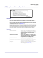
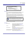
Note 1: The manual also supports the ZCL version
supplied in the old JN516x SDK installers JN-SW-4067
and JN-SW-4062 for Home Automation (HA) and
ZigBee Light Link (ZLL), respectively. However, it does
not support the ZCL version supplied in the current
combined ZLL/HA installer JN-SW-4168 - this newer
ZCL version is described in the ZCL User Guide with
part number JN-UG-3103.
Note 2: This manual assumes that you are already
familiar with the concepts of ZigBee application profiles,
devices, clusters and attributes. These are described in
the ZigBee PRO Stack User Guide (JN-UG-3048),
available from the NXP Wireless Connectivity TechZone
(see “Support Resources” on page 26).
Organisation
This manual is divided into four parts:
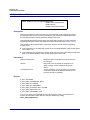
Part I: General and Development Information comprises four chapters:
Chapter 1 introduces the ZigBee Cluster Library (ZCL)
Chapter 2 describes some essential concepts for the ZCL, including read/
write access to cluster attributes and the associated read/write functions
Chapter 3 describes the event handling framework of the ZCL, including
the supplied event handling function
Chapter 4 describes the error handling provision of the ZCL, including the
supplied error handling function
Part II: Clusters and Modules comprises twenty-seven chapters (one chapter
per cluster or module):
JN-UG-3077 v2.1
Chapter 5 details the Basic cluster
Chapter 6 details the Power Configuration cluster
Chapter 7 details the Identify cluster
Chapter 8 details the Groups cluster
Chapter 9 details the Scenes cluster
Chapter 10 details the On/Off cluster
© NXP Laboratories UK 2015
23
About this Manual
Chapter 11 details the On/Off Switch Configuration cluster
Chapter 12 details the Level Control cluster
Chapter 13 details the Alarms cluster
Chapter 14 details the Time cluster, as well as the use of ZCL time
Chapter 15 details the Binary Input (Basic) cluster
Chapter 16 details the Commissioning cluster
Chapter 17 details the Door Lock cluster
Chapter 18 details the Thermostat cluster
Chapter 19 details the Thermostat UI Configuration cluster
Chapter 20 details the Colour Control cluster
Chapter 21 details the Illuminance Measurement cluster
Chapter 22 details the Illuminance Level Sensing cluster
Chapter 23 details the Temperature Measurement cluster
Chapter 24 details the Relative Humidity Measurement cluster
Chapter 25 details the Occupancy Sensing cluster
Chapter 26 details the IAS Zone cluster
Chapter 27 details the IAS ACE (Ancillary Control Equipment) cluster
Chapter 28 details the IAS WD (Warning Device) cluster
Chapter 29 details the OTA (Over-the-Air) Upgrade cluster
Chapter 30 details the Diagnostics cluster
Chapter 31 details the EZ-mode Commissioning module
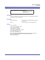
Part III: General Reference Information comprises three chapters:
Chapter 32 details the general functions of the ZCL
Chapter 33 details the general structures used by the ZCL
Chapter 34 details the general enumerations used by the ZCL
Part IV: Appendices describes the use of JenOS mutexes by the ZCL, the
attribute reporting mechanism, the ‘extended’ attribute discovery mechanism,
the JN516x bootloader operation, the OTA extension for dual-processor nodes
and the terminology to use with EZ-mode commissioning, as well as providing
useful example code fragments.
24
© NXP Laboratories UK 2015
JN-UG-3077 v2.1
ZigBee Cluster Library
User Guide
Conventions
Files, folders, functions and parameter types are represented in bold type.
Function parameters are represented in italics type.
Code fragments are represented in the Courier New typeface.
This is a Tip. It indicates useful or practical information.
This is a Note. It highlights important additional
information.
This is a Caution. It warns of situations that may result
in equipment malfunction or damage.
Acronyms and Abbreviations
ACE
Ancillary Control Equipment
API
Application Programming Interface
CIE
Control and Indicating Equipment
HA
Home Automation
IAS
Intruder Alarm System
OTA
Over The Air
SE
Smart Energy
UI
User Interface
ZCL
ZigBee Cluster Library
ZLL
ZigBee Light Link
JN-UG-3077 v2.1
© NXP Laboratories UK 2015
25
About this Manual
Related Documents
JN-UG-3048 ZigBee PRO Stack User Guide
JN-UG-3059 ZigBee Smart Energy User Guide
JN-UG-3076 ZigBee Home Automation User Guide
JN-UG-3091 ZigBee Light Link User Guide
JN-UG-3075 JenOS User Guide
JN-UG-3081 Jennic Encryption Tool (JET) User Guide
JN-UG-3103 ZigBee Cluster Library (ZLL/HA) User Guide [for JN-SW-4168]
075123
ZigBee Cluster Library Specification [from ZigBee Alliance]
095264
ZigBee Over-the-Air Upgrading Cluster [from ZigBee Alliance]
Support Resources
To access JN516x support resources such as SDKs, Application Notes and User
Guides, visit the Wireless Connectivity TechZone:
www.nxp.com/techzones/wireless-connectivity
All NXP resources referred to in this manual can be found at the above address,
unless otherwise stated.
Trademarks
All trademarks are the property of their respective owners.
Chip Compatibility
The ZCL software described in this manual can be used on the NXP JN516x family of
wireless microcontrollers with the exception of the JN5161 device. However, the
supported devices will be referred to as JN516x.
26
© NXP Laboratories UK 2015
JN-UG-3077 v2.1
ZigBee Cluster Library
User Guide
Part I:
General and Development
Information
JN-UG-3077 v2.1
© NXP Laboratories UK 2015
27
28
© NXP Laboratories UK 2015
JN-UG-3077 v2.1
ZigBee Cluster Library
User Guide
1. ZigBee Cluster Library (ZCL)
The ZigBee Alliance has defined the ZigBee Cluster Library (ZCL), comprising a
number of standard clusters that can be applied to different functional areas. For
example, all ZigBee application profiles use the Basic cluster from the ZCL.
The ZCL provides a common means for applications to communicate. It defines a
header and payload that sit inside the Protocol Data Unit (PDU) used for messages.
It also defines attribute types (such as ints, strings, etc), common commands (e.g. for
reading attributes) and default responses for indicating success or failure.
The NXP implementation of the ZCL, described in this manual, is supplied with the
NXP software for the following ZigBee application profiles:
Smart Energy (SE) [JN-SW-4064]
Home Automation (HA) [JN-SW-4067]
ZigBee Light Link (ZLL) [JN-SW-4062]
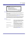
Note 1: This manual supports the ZCL version supplied
in the NXP JN516x SDK installers JN-SW-4064,
JN-SW-4067 and JN-SW-4062, as indicated above.
However, it does not support the ZCL version supplied
in the current combined ZLL/HA installer JN-SW-4168 this newer ZCL version is described in the ZCL User
Guide with part number JN-UG-3103.
The NXP JN516x ZigBee Smart Energy SDK (JN-SW-4064) is available from the NXP
Wireless Connectivity TechZone (see “Support Resources” on page 26). The ZCL is
fully detailed in the ZigBee Cluster Library Specification (075123), available from the
ZigBee Alliance.
The NXP ZCL software can be used on the NXP JN516x family of wireless
microcontrollers with the exception of the JN5161 device.
JN-UG-3077 v2.1
© NXP Laboratories UK 2015
29
Chapter 1
ZigBee Cluster Library (ZCL)
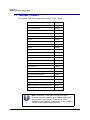
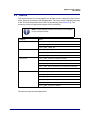
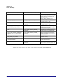
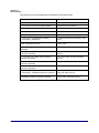
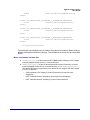
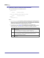
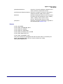
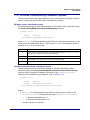
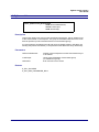
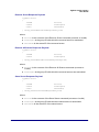
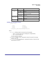
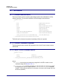
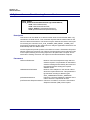
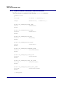
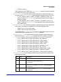
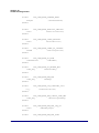
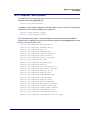
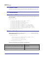
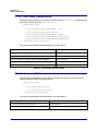
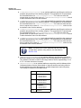
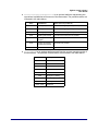
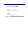
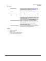
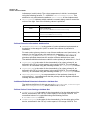
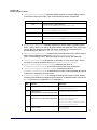
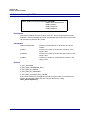
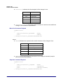
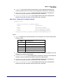
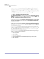
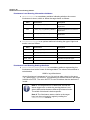
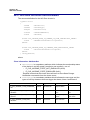
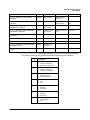
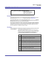
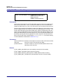
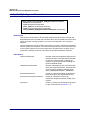
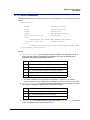
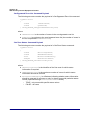
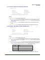
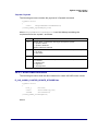
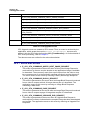
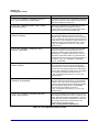
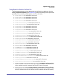
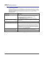
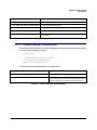
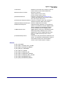
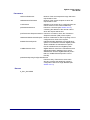
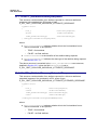
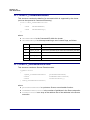
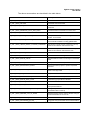
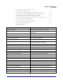
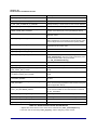
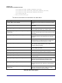
1.1 Member Clusters
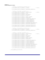
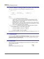
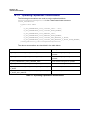
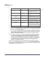
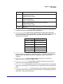
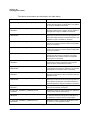
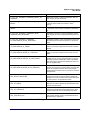
The clusters of the ZCL include those listed in Table 1 below.
General Cluster
Cluster ID
Basic
0x0000
Power Configuration
0x0001
Identify
0x0003
Groups
0x0004
Scenes
0x0005
On/Off
0x0006
On/Off Switch Configuration
0x0007
Level Control
0x0008
Alarms
0x0009
Time
0x000A
Binary Input (Basic)
0x000F
Commissioning
0x0015
Door Lock
0x0101
Thermostat
0x0201
Thermostat User Interface Configuration
0x0204
Colour Control
0x0300
Illuminance Measurement
0x0400
Illuminance Level Sensing
0x0401
Temperature Measurement
0x0402
Relative Humidity Measurement
0x0405
Occupancy Sensing
0x0406
IAS Zone
0x0500
IAS ACE (Ancillary Control Equipment)
0x0501
IAS WD (Warning Device)
0x0502
Table 1: ZCL Member Clusters
Note: In addition, a number of non-ZCL clusters/
modules which are common to all ZigBee profiles are
documented in this manual. These are the OTA
Upgrade cluster (0x0019), Diagnostics cluster (0x0B05)
and EZ-mode Commissioning module.
30
© NXP Laboratories UK 2015
JN-UG-3077 v2.1
ZigBee Cluster Library
User Guide
Basic
The Basic cluster contains the basic properties of a ZigBee device (e.g. software and
hardware versions) and allows the setting of user-defined properties (such as
location). The Basic cluster is detailed in Chapter 5.
Power Configuration
The Power Configuration cluster allows the details of a device’s power source(s) to be
determined and under/over voltage alarms to be configured. The Power Configuration
cluster is detailed in Chapter 6.
Identify
The Identify cluster allows a ZigBee device to make itself known visually (e.g. by
flashing a light) to an observer such as a network installer. The Identify cluster is
detailed in Chapter 7.
Groups
The Groups cluster allows the management of the Group table concerned with group
addressing - that is, the targeting of multiple endpoints using a single address. The
Groups cluster is detailed in Chapter 8.
Scenes
The Scenes cluster allows the management of pre-defined sets of cluster attribute
values called scenes, where a scene can be stored, retrieved and applied to put the
system into a pre-determined state. The Scenes cluster is detailed in Chapter 9.
On/Off
The On/Off cluster allows a device to be put into the ‘on’ and ‘off’ states, or toggled
between the two states. The On/Off cluster is detailed in Chapter 10.
On/Off Switch Configuration
The On/Off Switch Configuration cluster allows the switch type on a device to be
defined, as well as the commands to be generated when the switch is moved between
its two states. The On/Off Switch Configuration cluster is detailed in Chapter 11.
Level Control
The Level Control cluster allows control of the level of a physical quantity (e.g. heat
output) on a device. The Level Control cluster is detailed in Chapter 12.
Alarms
The Alarms cluster is used for sending alarm notifications and the general
configuration of alarms for all other clusters on the ZigBee device (individual alarm
conditions are set in the corresponding clusters). The Alarms cluster is detailed in
Chapter 13.
JN-UG-3077 v2.1
© NXP Laboratories UK 2015
31
Chapter 1
ZigBee Cluster Library (ZCL)
Time
The Time cluster provides an interface to a real-time clock on a ZigBee device,
allowing the clock time to be read and written in order to synchronise the clock to a
time standard - the number of seconds since 0 hrs 0 mins 0 secs on 1st January 2000
UTC (Co-ordinated Universal Time). This cluster includes functionality for local timezone and daylight saving time. The Time cluster is detailed in Chapter 14.
Binary Input (Basic)
The Binary Input (Basic) cluster provides an interface for accessing a binary
measurement and its associated characteristics, and is typically used to implement a
sensor that measures a two-state physical quantity. The Binary Input (Basic) cluster
is detailed in Chapter 15.
Commissioning
The Commissioning cluster can be optionally used for commissioning the ZigBee
stack on a device (during network installation) and defining the device behaviour with
respect to the ZigBee network (it does not affect applications operating on the
devices). The Commissioning cluster is detailed in Chapter 16.
Door Lock
The Door Lock cluster provides a means of representing the state of a door lock and
(optionally) the door. The Door Lock cluster is detailed in Chapter 17.
Thermostat
The Thermostat cluster provides a means of configuring and controlling the
functionality of a thermostat. The Thermostat cluster is detailed in Chapter 18.
Thermostat User Interface (UI) Configuration
The Thermostat UI Configuration cluster provides a means of configuring the user
interface (keypad and/or LCD screen) for a thermostat or a thermostat controller
device. The Thermostat UI Configuration cluster is detailed in Chapter 19.
Colour Control
The Colour Control cluster can be used to adjust the colour of a light (it does not
govern the overall luminance of the light, as this is controlled using the Level Control
cluster). The Colour Control cluster is detailed in Chapter 20.
Illuminance Measurement
The Illuminance Measurement cluster provides an interface to an illuminance
measuring device, allowing the configuration of measuring and the reporting of
measurements. The Illuminance Measurement cluster is detailed in Chapter 21.
32
© NXP Laboratories UK 2015
JN-UG-3077 v2.1
ZigBee Cluster Library
User Guide
Illuminance Level Sensing
The Illuminance Level Sensing cluster provides an interface to light-level sensing
functionality. The Illuminance Level Sensing cluster is detailed in Chapter 22.
Temperature Measurement
The Temperature Measurement cluster provides an interface to a temperature
measuring device, allowing the configuration of measuring and the reporting of
measurements. The Temperature Measurement cluster is detailed in Chapter 23.
Relative Humidity Measurement
The Relative Humidity Measurement cluster provides an interface to a humidity
measuring device, allowing the configuration of relative humidity measuring and the
reporting of measurements. The Relative Humidity Measurement cluster is detailed in
Chapter 24.
Occupancy Sensing
The Occupancy Sensing cluster provides an interface to an occupany sensor, allowing
the configuration of sensing and the reporting of status. The Occupancy Sensing
cluster is detailed in Chapter 25.
IAS Zone
The IAS Zone cluster provides an interface to a zone device in an IAS (Intruder Alarm
System). The IAS Zone cluster is detailed in Chapter 26.
IAS ACE (Ancillary Control Equipment)
The IAS ACE cluster provides a control interface to a CIE (Control and Indicating
Equipment) device in an IAS (Intruder Alarm System). The IAS ACE cluster is detailed
in Chapter 27.
IAS WD (Warning Device)
The IAS WD cluster provides an interface to a Warning Device in an IAS (Intruder
Alarm System). For example, a CIE (Control and Indicating Equipment) device can
use the cluster to issue alarm warning indications to a Warning Device when an alarm
condition is detected. The IAS WD cluster is detailed in Chapter 28.
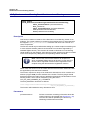
Note: Some of the above clusters have special
attributes that are used in ZigBee Light Link (ZLL) but in
no other application profile. If required, these attributes
must be enabled at compile-time (see Section 1.2).
JN-UG-3077 v2.1
© NXP Laboratories UK 2015
33
Chapter 1
ZigBee Cluster Library (ZCL)
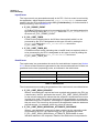
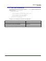
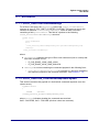
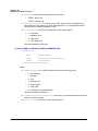
1.2 Compile-time Options
Before the application can be built, the ZCL compile-time options must be configured
in the header file zcl_options.h for the application.
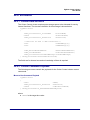
Enabled Clusters
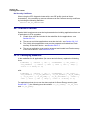
All required clusters must be enabled in the options header file. For example, to enable
the Basic and Time clusters:
#define CLD_BASIC
#define CLD_TIME
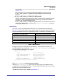
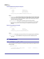
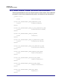
Support for Attribute Read/Write
Read/write access to cluster attributes must be explicitly compiled into the application,
and must be enabled separately for the server and client sides of a cluster using the
following macros in the options header file:
#define ZCL_ATTRIBUTE_READ_SERVER_SUPPORTED
#define ZCL_ATTRIBUTE_READ_CLIENT_SUPPORTED
#define ZCL_ATTRIBUTE_WRITE_SERVER_SUPPORTED
#define ZCL_ATTRIBUTE_WRITE_CLIENT_SUPPORTED
Each of the above definitions will apply to all clusters used in the application.
Tip: If only read access to attributes is required then do
not enable write access, as omitting the write options
will give the benefit of a reduced application size.
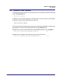
Optional and ZLL Attributes
Many clusters have optional attributes that may be enabled at compile-time via the
options header file - for example, to enable the Time Zone attribute in the Time cluster:
#define E_CLD_TIME_ATTR_TIME_ZONE
The ZigBee Light Link (ZLL) application profile uses special attributes in the ZCL
clusters. These attributes are not needed for other application profiles and must be
enabled for ZLL by including the appropriate defines in the options header file.
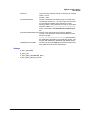
Note: Cluster-specific compile-time options are detailed
in the sections for the individual clusters in Chapter 5.
The following optional features also have their own
compile-time options: attribute reporting (see Appendix
B.2.1) and OTA upgrade (see Section 29.12).
34
© NXP Laboratories UK 2015
JN-UG-3077 v2.1
ZigBee Cluster Library
User Guide
2. ZCL Fundamentals and Features
This chapter describes essential ZCL concepts, including the use of shared device
structures as well as remote read and write accesses to cluster attributes. The
attribute access functions are also detailed that are provided in the NXP
implementation of the ZCL.
Note: ZCL functions are referred to in this chapter which
are detailed in Chapter 32.
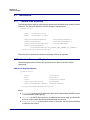
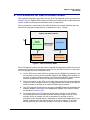
2.1 Shared Device Structures
In each ZigBee device, cluster attribute values are exchanged between the application
and the ZCL by means of a shared structure. This structure is protected by a mutex see Appendix A. The structure for a particular ZigBee device contains structures for
the clusters supported by that device.
Note: In order to use a cluster which is supported by a
device, the relevant option for the cluster must be
specified at build-time - see Section 1.2.
A shared device structure may be used in either of the following ways:
The local application writes attribute values to the structure, allowing the ZCL to
respond to commands relating to these attributes. For example, a Smart
Energy Metering Device application writes energy consumption data to the
local Metering structure and this data is subsequently read remotely by the
utility company.
The ZCL parses incoming commands that write attribute values to the
structure. The written values can then be read by the local application. For
example, in a Smart Energy network, data is remotely written to an IPD
structure by the ESP application and the IPD application then reads this data to
display it on a screen.
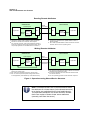
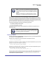
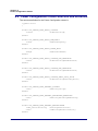
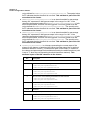
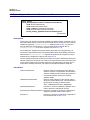
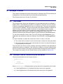
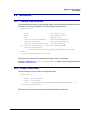
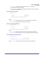
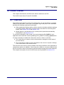
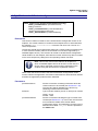
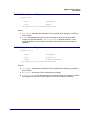
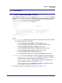
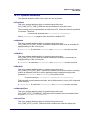
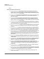
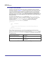
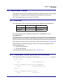
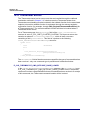
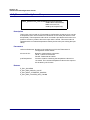
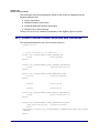
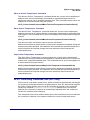
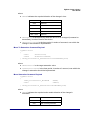
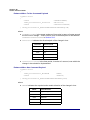
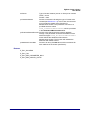
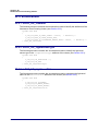
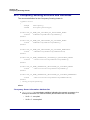
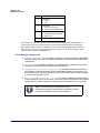
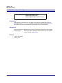
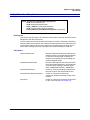
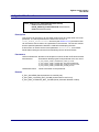
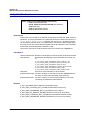
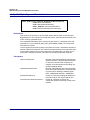
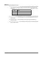
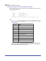
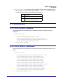
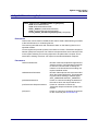
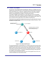
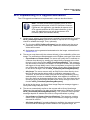
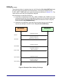
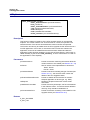
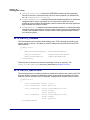
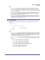
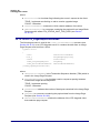
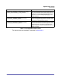
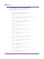
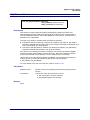
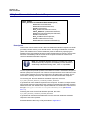
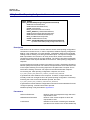
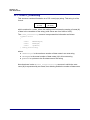
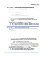
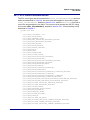
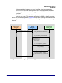
Remote read and write operations involving a shared device structure are illustrated
in Figure 1 below. Normally, these operations are requested by a cluster client and
performed on a cluster server. For more detailed descriptions of these operations,
refer to Section 2.2.
JN-UG-3077 v2.1
© NXP Laboratories UK 2015
35
Chapter 2
ZCL Fundamentals and Features
Reading Remote Attributes
Client Device
Server Device
Read
Command
Read Request
Application
Read
Device
Structure
(Copy)
ZCL
Write
ZCL
Read
Response
Application
Device
Structure
Write
Event (s)
2. If necessary, application first updates attribute values in
device structure.
3. ZCL reads requested attribute values from device structure
and then returns them to requesting client .
1. Application requests read of attribute values from device
structure on remote server and ZCL sends request .
4. ZCL receives response, writes received attribute values to
local copy of device structure and generates events (which
can prompt application to read attributes from structure ).
Writing Remote Attributes
Client Device
Server Device
Write
Command
Write Request
Application
Write
Device
Structure
(Copy)
ZCL
ZCL
Write
Read
Response
Device
Structure
Application
Read
Event (s)
1. Application writes new attribute values to local copy of device
structure for remote server.
2. ZCL sends 'write attributes' request to remote server.
6. ZCL can receive optional response and generate events
for the application (that indicate any unsuccessful writes).
3. ZCL writes received attribute values to device structure and
optionally sends response to client.
4. If required, application can then read new attribute values
from device structure.
5. ZCL can optionally generate a ‘write attributes’ response .
Figure 1: Operations using Shared Device Structure
Note: Provided that there are no remote attribute writes,
the attributes of a cluster server (in the shared structure)
on a device are maintained by the local application(s).
The equivalent attributes of a cluster client on another
device are copies of these cluster server attributes
(remotely read from the server).
36
© NXP Laboratories UK 2015
JN-UG-3077 v2.1
ZigBee Cluster Library
User Guide
2.2 Accessing Attributes
This section describes the processes of reading and writing cluster attributes on a
remote node. For the attribute access function descriptions, refer to Section 32.2.
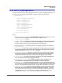
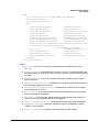
2.2.1 Reading Attributes
A common operation in a ZigBee PRO application is to read attributes from a remote
device, e.g. in a Smart Energy network, an In-Premise Display (IPD) device may need
to obtain data from a Metering device. Attributes are read by sending a ‘read attributes’
request, normally from a client cluster to a server cluster. This request can be sent
using a general ZCL function or using a function which is specific to the target cluster.
The cluster-specific functions for reading attributes are covered in the chapters of this
manual that describe the supported clusters. Note that read access to cluster
attributes must be explicitly enabled at compile-time as described in Section 1.2.
ZCL functions are provided for reading a set of attributes or all attributes of a remote
cluster instance, as described in Section 2.2.1.1 and Section 2.2.1.2. A function is also
provided for reading a local cluster attribute value, as described in Section 2.2.1.3.
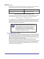
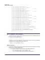
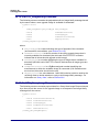
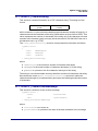
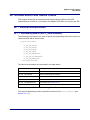
2.2.1.1
Reading a Set of Attributes of a Remote Cluster
This section describes the use of the function eZCL_SendReadAttributesRequest()
to send a ‘read attributes’ request to a remote cluster in order to obtain the values of
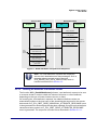
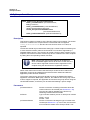
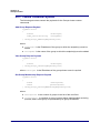
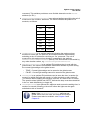
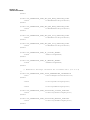
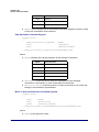
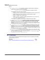
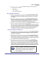
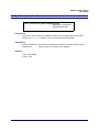
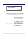
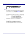
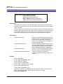
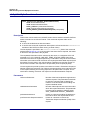
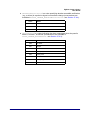
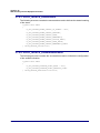
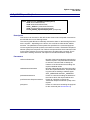
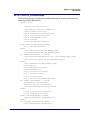
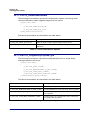
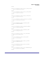
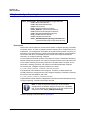
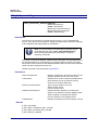
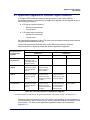
selected attributes. The resulting activities on the source and destination nodes are
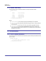
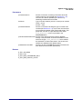
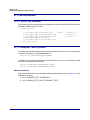
outlined below and illustrated in Figure 2. Note that instances of the shared device
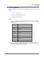
structure (which contains the relevant attributes) exist on both the source and
destination nodes. The events generated from a ‘read attributes’ request are further
described in Chapter 3.
Note: The described sequence is similar when using the
cluster-specific ‘read attributes’ functions and the
eZCL_ReadAllAttributes() function.
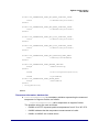
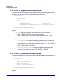
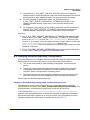
1. On Source Node
The function eZCL_SendReadAttributesRequest() is called to submit a request to
read one or more attributes on a cluster on a remote node. The information required
by this function includes the following:
Source endpoint (from which the read request is to be sent)
Address of destination node for request
Destination endpoint (on destination node)
Identifier of the cluster containing the attributes [enumerations provided]
Number of attributes to be read
Array of identifiers of attributes to be read [enumerations provided]
JN-UG-3077 v2.1
© NXP Laboratories UK 2015
37
Chapter 2
ZCL Fundamentals and Features
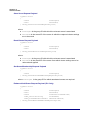
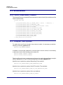
2. On Destination Node
On receiving the ‘read attributes’ request, the ZCL software on the destination node
performs the following steps:
1. Generates an E_ZCL_CBET_READ_REQUEST event for the destination
endpoint callback function which, if required, can update the shared device
structure that contains the attributes to be read, before the read takes place.
2. Generates an E_ZCL_CBET_LOCK_MUTEX event for the endpoint callback
function, which should lock the mutex that protects the shared device
structure - for information on mutexes, refer to Appendix A.
3. Reads the relevant attribute values from the shared device structure and
creates a ‘read attributes’ response message containing the read values.
4. Generates an E_ZCL_CBET_UNLOCK_MUTEX event for the endpoint
callback function, which should now unlock the mutex that protects the shared
device structure (other application tasks can now access the structure).
5. Sends the ‘read attributes’ response to the source node of the request.
3. On Source Node
On receiving the ‘read attributes’ response, the ZCL software on the source node
performs the following steps:
1. Generates an E_ZCL_CBET_LOCK_MUTEX event for the source endpoint
callback function, which should lock the mutex that protects the relevant
shared device structure on the source node.
2. Writes the new attribute values to the shared device structure on the source
node.
3. Generates an E_ZCL_CBET_UNLOCK_MUTEX event for the endpoint
callback function, which should now unlock the mutex that protects the shared
device structure (other application tasks can now access the structure).
4. For each attribute listed in the ‘read attributes’ response, it generates an
E_ZCL_CBET_READ_INDIVIDUAL_ATTRIBUTE_RESPONSE message for
the source endpoint callback function, which may or may not take action on
this message.
5. On completion of the parsing of the ‘read attributes’ response, it generates a
single E_ZCL_CBET_READ_ATTRIBUTES_RESPONSE message for the
source endpoint callback function, which may or may not take action on this
message.
38
© NXP Laboratories UK 2015
JN-UG-3077 v2.1
ZigBee Cluster Library
User Guide
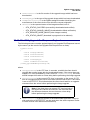
Source Node
Endpoint
Destination Node
ZCL
ZCL
Endpoint
'Read Attributes' Message
'Read Attributes' Request
READ_REQUEST
LOCK_MUTEX
Read Attribute Values
Shared
Structure
UNLOCK_MUTEX
LOCK_MUTEX
Local
Shared
Structure
'Read Attributes' Response
Write Attribute Values
UNLOCK_MUTEX
READ_INDIVIDUAL_
ATTRIBUTE_RESPONSE
READ_ATTRIBUTES
_RESPONSE
Figure 2: ‘Read Attributes’ Request and Response
Note: The ‘read attributes’ requests and responses
arrive at their destinations as data messages. Such a
message triggers a stack event of the type
ZPS_EVENT_APS_DATA_INDICATION, which is
handled as described in Section 3.2.
2.2.1.2
Reading All Attributes of a Remote Cluster
The function eZCL_ReadAllAttributes() allows a ‘read attributes’ request to be sent
to a remote cluster in order to obtain the values of all server or client attributes,
depending on the type of cluster instance (server or client).
On receiving the ‘read attributes’ response, the obtained attribute values are
automatically written to the local copy of the shared device structure for the remote
device and an E_ZCL_CBET_READ_INDIVIDUAL_ATTRIBUTE_RESPONSE event
is then generated for each attribute that has been updated. Once all received attribute
values have been parsed, an E_ZCL_CBET_READ_ATTRIBUTES_RESPONSE
event is generated. The sequence is similar to that described in Section 2.2.1.1.
JN-UG-3077 v2.1
© NXP Laboratories UK 2015
39
Chapter 2
ZCL Fundamentals and Features
The response may not contain values for all requested attributes and so further
responses may follow. The first E_ZCL_CBET_READ_ATTRIBUTES_RESPONSE
should prompt the application to call eZCL_HandleReadAttributesResponse() in
order to ensure that all cluster attributes are received from the remote node. This
function should normally be included in the user-defined callback function that is
invoked by the event E_ZCL_CBET_READ_ATTRIBUTES_RESPONSE. If the 'read
attributes' response is not complete, this function will re-send 'read attributes' requests
until all relevant attribute values have been received.
2.2.1.3
Reading an Attribute of a Local Cluster
An individual attribute of a cluster on the local node can be read using the function
eZCL_ReadLocalAttributeValue(). The read value is returned by the function (in a
memory location for which a pointer must be provided).
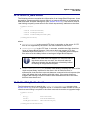
2.2.2 Writing Attributes
The ZCL provides functions for writing attribute values to both remote and local
clusters, as described in Section 2.2.2.1 and Section 2.2.2.2 respectively.
2.2.2.1
Writing to Attributes of a Remote Cluster
Some ZigBee PRO applications may need to write attribute values to a remote cluster
- for example, in a Smart Energy network, an Energy Service Portal (ESP) may need
to write attributes to a Load Control Device (e.g to configure the device group).
Attribute values are written by sending a ‘write attributes’ request, normally from a
client cluster to a server cluster, where the relevant attributes in the shared device
structure are updated. Note that write access to cluster attributes must be explicitly
enabled at compile-time as described in Section 1.2.
Three ‘write attributes’ functions are provided in the ZCL:
eZCL_SendWriteAttributesRequest(): This function sends a ‘write attributes’
request to a remote device, which attempts to update the attributes in its shared
structure. The remote device generates a ‘write attributes’ response to the
source device, indicating success or listing error codes for any attributes that it
could not update.
eZCL_SendWriteAttributesNoResponseRequest(): This function sends a
‘write attributes’ request to a remote device, which attempts to update the
attributes in its shared structure. However, the remote device does not
generate a ‘write attributes’ response, regardless of whether there are errors.
eZCL_SendWriteAttributesUndividedRequest(): This function sends a ‘write
attributes’ request to a remote device, which checks that all the attributes can
be written to without error:
If all attributes can be written without error, all the attributes are updated.
If any attribute is in error, all the attributes are left at their existing values.
The remote device generates a ‘write attributes’ response to the source device,
indicating success or listing error codes for attributes that are in error.
40
© NXP Laboratories UK 2015
JN-UG-3077 v2.1
ZigBee Cluster Library
User Guide
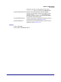
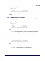
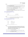
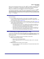
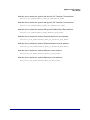
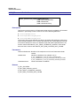
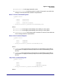
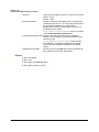
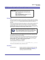
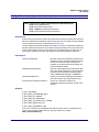
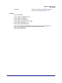
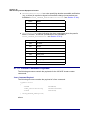
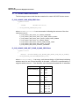
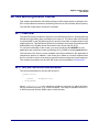
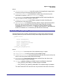
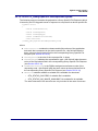
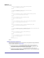
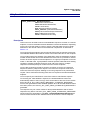
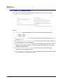
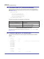
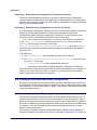
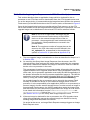
The activities surrounding a ‘write attributes’ request on the source and destination
nodes are outlined below and illustrated in Figure 3. Note that instances of the shared
device structure (which contains the relevant attributes) must be maintained on both
the source and destination nodes. The events generated from a ‘write attributes’
request are further described in Chapter 3.
1. On Source Node
In order to send a ‘write attributes’ request, the application on the source node
performs the following steps:
1. Locks the mutex that protects the local instance of the shared device structure
that contains the attributes to be updated - for information on mutexes, refer to
Appendix A.
2. Writes one or more updated attribute values to the local instance of the shared
device structure.
3. Unlocks the mutex that protects the local instance of the shared device
structure.
4. Calls one of the above ZCL ‘write attributes’ functions to submit a request to
update the relevant attributes on a cluster on a remote node. The information
required by this function includes the following:
Source endpoint (from which the write request is to be sent)
Address of destination node for request
Destination endpoint (on destination node)
Identifier of the cluster containing the attributes [enumerations provided]
Number of attributes to be written
Array of identifiers of attributes to be written [enumerations provided]
From the above information, the function is able to pick up the relevant attribute
values from the local instance of the shared structure and incorporate them in
the message for the remote node.
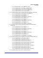
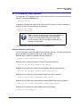
2. On Destination Node
On receiving the ‘write attributes’ request, the ZCL software on the destination node
performs the following steps:
1. For each attribute to be written, generates an
E_ZCL_CBET_CHECK_ATTRIBUTE_RANGE event for the destination
endpoint callback function.
If required, the callback function can do either or both of the following:
check that the new attribute value is in the correct range - if the value is
out-of-range, the function should set the eAttributeStatus field of the
event to E_ZCL_ERR_ATTRIBUTE RANGE
block the write by setting the the eAttributeStatus field of the event to
E_ZCL_DENY_ATTRIBUTE_ACCESS
In the case of an out-of-range value or a blocked write, there is no further
processing for that particular attribute following the ‘write attributes’ request.
JN-UG-3077 v2.1
© NXP Laboratories UK 2015
41
Chapter 2
ZCL Fundamentals and Features
2. Generates an E_ZCL_CBET_LOCK_MUTEX event for the endpoint callback
function, which should lock the mutex that protects the relevant shared device
structure - for information on mutexes, refer to Appendix A.
3. Writes the relevant attribute values to the shared device structure - an
E_ZCL_CBET_WRITE_INDIVIDUAL_ATTRIBUTE event is generated for
each individual attempt to write an attribute value, which the endpoint callback
function can use to keep track of the successful and unsuccessful writes.
Note that if an ‘undivided write attributes’ request was received, an individual
failed write will render the whole update process unsuccessful.
4. Generates an E_ZCL_CBET_WRITE_ATTRIBUTES event to indicate that all
relevant attributes have been processed and, if required, creates a ‘write
attributes’ response message for the source node.
5. Generates an E_ZCL_CBET_UNLOCK_MUTEX event for the endpoint
callback function, which should now unlock the mutex that protects the shared
device structure (other application tasks can now access the structure).
6. If required, sends a ‘write attributes’ response to the source node of the
request.
3. On Source Node
On receiving an optional ‘write attributes’ response, the ZCL software on the source
node performs the following steps:
1. For each attribute listed in the ‘write attributes’ response, it generates an
E_ZCL_CBET_WRITE_INDIVIDUAL_ATTRIBUTE_RESPONSE message for
the source endpoint callback function, which may or may not take action on
this message. Only attributes for which the write has failed are included in the
response and will therefore result in one of these events.
2. On completion of the parsing of the ‘write attributes’ response, it generates a
single E_ZCL_CBET_WRITE_ATTRIBUTES_RESPONSE message for the
source endpoint callback function, which may or may not take action on this
message.
42
© NXP Laboratories UK 2015
JN-UG-3077 v2.1
ZigBee Cluster Library
User Guide
Source Node
Endpoint
Destination Node
ZCL
ZCL
Endpoint
Lock mutex for
local shared structure
Local
Shared
Structure
Write attribute values
Unlock mutex for
local shared structure
'Write Attributes' Message
'Write Attributes' Request
CHECK_ATTRIBUTE_RANGE
LOCK_MUTEX
Write Attribute Value
Shared
Structure
WRITE_INDIVIDUAL_ATTRIBUTE
WRITE_ATTRIBUTES
UNLOCK_MUTEX
'Write Attributes' Response
WRITE_INDIVIDUAL_
ATTRIBUTE_RESPONSE
WRITE_ATTRIBUTES
_RESPONSE
Figure 3: ‘Write Attributes’ Request and Response
Note: The ‘write attributes’ requests and responses
arrive at their destinations as data messages. Such a
message triggers a stack event of the type
ZPS_EVENT_APS_DATA_INDICATION, which is
handled as described in Chapter 3.
2.2.2.2
Writing an Attribute Value to a Local Cluster
An individual attribute of a cluster on the local node can be written to using the function
eZCL_WriteLocalAttributeValue(). The function is blocking, returning only once the
value has been written.
JN-UG-3077 v2.1
© NXP Laboratories UK 2015
43
Chapter 2
ZCL Fundamentals and Features
2.2.3 Attribute Discovery
A ZigBee cluster may have mandatory and/or optional attributes. The desired optional
attributes are enabled in the cluster structure. An application running on a cluster client
may need to discover which optional attributes are supported by the cluster server.
For example, in the case of the Simple Metering cluster of the Smart Energy profile,
those attributes corresponding to the quantities to be metered are enabled on the
Metering Device which acts as the cluster server. An IPD, which is a cluster client, may
only be able to display Current Summation and Instantaneous Demand.
Instantaneous Demand is an optional attribute, so the IPD would need to discover
whether the Metering Device supports it.
The ZCL provides functionality to perform the necessary ‘attribute discovery’, as
described in the rest of this section.
Note 1: ‘Extended’ attribute discovery is also available
in which the accessibility of each reported attribute is
also indicated. This is described in Appendix C.
Note 2: Alternatively, the application on a cluster client
can check whether a particular attribute exists on the
cluster server by attempting to read the attribute (see
Section 2.2.1) - if the attribute does not exist on the
server, an error will be returned.
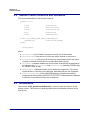
Compile-time Options
If required, the attribute discovery feature must be explicitly enabled on the cluster
server and client at compile-time by respectively including the following defines in the
zcl_options.h files:
#define ZCL_ATTRIBUTE_DISCOVERY_SERVER_SUPPORTED
#define ZCL_ATTRIBUTE_DISCOVERY_CLIENT_SUPPORTED
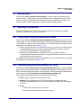
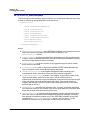
Application Coding
The application on a cluster client can initiate a discovery of the attributes on the
cluster server by calling the function eZCL_SendDiscoverAttributesRequest(),
which sends a ‘discover attributes’ request to the server. This function allows a range
of attributes to be searched for, defined by:
The ‘start’ attribute in the range (the attribute identifier must be specified)
The number of attributes in the range
Initially, the start attribute should be set to the first attribute of the cluster. If the
discovery request does not return all the attributes used on the cluster server, the
above function should be called again with the start attribute set to the next
‘undiscovered’ attribute. Multiple function calls may be required to discover all of the
attributes used on the server.
44
© NXP Laboratories UK 2015
JN-UG-3077 v2.1
ZigBee Cluster Library
User Guide
On receiving a discover attributes request, the server handles the request
automatically (provided that attribute discovery has been enabled in the compile-time
options - see above) and replies with a ‘discover attributes’ response containing the
requested information.
The arrival of this response at the client results in an
E_ZCL_CBET_DISCOVER_INDIVIDUAL_ATTRIBUTE_RESPONSE event for each
attribute reported in the response. Therefore, multiple events will normally result from
a single discover attributes request. This event contains details of the reported
attribute in a tsZCL_AttributeDiscoveryResponse structure (see Section
33.1.10).
Following the event for the final attribute reported, the event
E_ZCL_CBET_DISCOVER_ATTRIBUTES_RESPONSE is generated to indicate that
all attributes from the discover attributes response have been reported.
2.2.4 Attribute Reporting
A cluster client can poll the value of an attribute on the cluster server by sending a
‘read attributes’ request, as described in Section 2.2.1. Alternatively, the server can
issue unsolicited attribute reports to the client using the ‘attribute reporting’ feature (in
which case there is no need for the client to request attribute values).
The attribute reporting mechanism reduces network traffic compared with the polling
method. It also allows a sleeping server to report its attribute values while it is awake.
Attribute reporting is an optional feature and is not supported by all devices.
Note: This section only introduces attribute reporting.
This optional feature is fully described in Appendix B.
An ‘attribute report’ (from server to client) can be triggered in one of the following ways:
by the user application (on the server device)
automatically (triggered by a change in the attribute value or periodically)
Automatic attribute reporting is more fully described in Appendix B.1.
The rules for automatic reporting can be configured by a remote device by sending a
‘configure reporting’ command to the server using the function
eZCL_SendConfigureReportingCommand(). If it is required, automatic attribute
reporting must also be enabled at compile-time on both the cluster server and client.
The configuration of attribute reporting is detailed in Appendix B.2.
Note: Attribute reporting configuration data should be
preserved in Non-Volatile Memory (NVM) to allow
automatic attribute reporting to resume following a reset
of the server device. Persisting this data in NVM is
described in Appendix B.6.
JN-UG-3077 v2.1
© NXP Laboratories UK 2015
45
Chapter 2
ZCL Fundamentals and Features
An attribute report for all attributes on the server can be issued directly by the server
application using the function eZCL_ReportAllAttributes(). This method of attribute
reporting does not require any configuration and does not need to be enabled at
compile-time on the server, although the client still needs to be enabled at compiletime to receive attribute reports.
Sending an attribute report from the server is further described in Appendix B.3 and
receiving an attribute report on the client is described in Appendix B.4.
2.3 Default Responses
The ZCL provides a default response which is generated in reply to a unicast
command in the following circumstances:
when there is no other relevant response and the requirement for default
responses has not been disabled on the endpoint that sent the command
when an error results from a unicast command and there is no other relevant
response, even if the requirement for default responses has been disabled on
the endpoint that sent the command
The default response disable setting is made in the bDisableDefaultResponse
field of the structure tsZCL_EndPointDefinition detailed in Section 33.1.1. This
setting dictates the value of the ‘disable default response’ bit in messages sent by the
endpoint. The receiving device then uses this bit to determine whether to return a
default response to the source device.
The default response includes the ID of the command that triggered the response and
a status field (see Section 33.1.9). Therefore, in the case of an error, the identity of the
command that caused the error will be contained in the command ID field of the default
response.
Note that the default response can be generated on reception of all commands,
including responses (e.g. a ‘read attributes’ response) but not other default responses.
2.4 Bound Transmission Management
ZigBee PRO provides the facility for bound transfers/transmissions. In this case, a
source endpoint on one node is bound to one or more destination endpoints on other
nodes. Data sent from the source endpoint is then automatically transmitted to all the
bound endpoints (without the need to specify destination addresses). The bound
transmission is handled by a Bind Request Server on the source node. Binding, bound
transfers and the Bind Request Server are fully described in the ZigBee PRO Stack
User Guide (JN-UG-3048).
Congestion may occur if a new bound transmission is requested while the Bind
Request Server is still busy completing the previous bound transmission (still sending
packets to bound nodes). This causes the new bound transmission to fail. The ZCL
software incorporates a feature for managing bound transmission requests, so not to
overload the Bind Request Server and cause transmissions to fail.
46
© NXP Laboratories UK 2015
JN-UG-3077 v2.1
ZigBee Cluster Library
User Guide
Note 1: This feature for managing bound transmissions
is not strictly a part of the ZCL but is provided in the ZCL
software since it may be used with all ZigBee application
profiles.
Note 2: The alternative to using this feature is for the
application to re-attempt bound transmissions that fail.
If this feature is enabled and a bound transmission request submitted to the Bind
Request Server fails, the bound transmission APDU is automatically put into a queue.
A one-second scheduler periodically takes the APDU at the head of the queue and
submits it to the Bind Request Server for transmission. If this bound transmission also
fails, the APDU will be returned to the bound transmission queue.
The bound transmission queue has the following properties:
Number of buffers in the queue
Size of each buffer, in bytes
The feature is enabled and the above properties are defined at compile-time, as
described below.
Note: If a single APDU does not fit into a single buffer in
the queue, it will be stored in multiple buffers (provided
that enough buffers are available).
Compile-time Options
In order to use the bound transmission management feature, the following definitions
are required in the zcl_options.h file.
Add this line to enable the bound transmission management feature:
#define CLD_BIND_SERVER
Add this line to define the number of buffers in the bound transmission queue (in this
example, the queue will contain four buffers):
#define MAX_NUM_BIND_QUEUE_BUFFERS
4
Add this line to define the size, in bytes, of a buffer in the bound transmission queue
(in this example, the buffer size is 60 bytes):
#define MAX_PDU_BIND_QUEUE_PAYLOAD_SIZE
60
Certain clusters and the ‘attribute reporting’ feature allow APS acknowledgements to
be disabled for bound transmissions. The required definitions are detailed in the
cluster-specific compile-time options.
JN-UG-3077 v2.1
© NXP Laboratories UK 2015
47
Chapter 2
ZCL Fundamentals and Features
2.5 Command Discovery
The ZCL provides the facility to discover the commands that a cluster instance on a
remote device can receive and generate. This is useful since an individual cluster
instance may not be able to receive or generate all of the commands that are
theoretically supported by the cluster.
The commands that are supported by a cluster (and that can therefore potentially be
discovered) are defined in a Command Definition table which is enabled in the cluster
definition when Command Discovery is enabled (see Section 33.1.2).
Two ZCL functions are provided to implement the Command Discovery feature (as
indicated in Section 2.5.1 below and fully described in Section 32.3).
2.5.1 Discovering Command Sets
The commands supported by a remote cluster instance can be discovered as
described below.
Discovering commands that can be received
The commands that can be received by an instance of a cluster on a remote device
can be discovered using the function
eZCL_SendDiscoverCommandReceivedRequest()
This function sends a request to the remote cluster instance, which responds with a
list of commands (identified by their Command IDs). On receiving this response, the
following events are generated on the local device:
E_ZCL_CBET_DISCOVER_INDIVIDUAL_COMMAND_RECEIVED_RESPONSE
This event is generated for each individual command reported in the response.
The reported information is contained in a structure of the type
tsZCL_CommandDiscoveryIndividualResponse (see Section 33.1.17).
E_ZCL_CBET_DISCOVER_COMMAND_RECEIVED_RESPONSE
This event is generated after all the above individual events, in order to indicate
the end of these events. The reported information is contained in a structure of
the type tsZCL_CommandDiscoveryResponse (see Section 33.1.18).
48
© NXP Laboratories UK 2015
JN-UG-3077 v2.1
ZigBee Cluster Library
User Guide
Discovering commands that can be generated
The commands that can be generated by an instance of a cluster on a remote device
can be discovered using the function
eZCL_SendDiscoverCommandGeneratedRequest()
This function sends a request to the remote cluster instance, which responds with a
list of commands (identified by their Command IDs). On receiving this response, the
following events are generated on the local device:
E_ZCL_CBET_DISCOVER_INDIVIDUAL_COMMAND_GENERATED_RESPONSE
This event is generated for each individual command reported in the response.
The reported information is contained in a structure of the type
tsZCL_CommandDiscoveryIndividualResponse (see Section 33.1.17).
E_ZCL_CBET_DISCOVER_COMMAND_GENERATED_RESPONSE
This event is generated after all the above individual events, in order to indicate
the end of these events. The reported information is contained in a structure of
the type tsZCL_CommandDiscoveryResponse (see Section 33.1.18).
Note: The above functions can be called multiple times
to discover the commands in stages. After each call, the
tsZCL_CommandDiscoveryResponse structure
contains a Boolean flag which indicates whether there
are more commands to be discovered (see Section
33.1.18). For full details, refer to the function
descriptions in Section 32.3.
2.5.2 Compile-time Options
If required, the Command Discovery feature must be enabled at compile-time.
To enable the feature, the following must be defined at both the local and remote ends:
#define ZCL_COMMAND_DISCOVERY_SUPPORTED
To enable the handling of Command Discovery requests (and the generation of
responses) at the remote end, the following must be defined on the remote device:
#define ZCL_COMMAND_RECEIVED_DISCOVERY_SERVER_SUPPORTED
To enable the handling of Command Discovery responses at the local end, the
following must be defined on the local device:
#define ZCL_COMMAND_RECEIVED_DISCOVERY_CLIENT_SUPPORTED
JN-UG-3077 v2.1
© NXP Laboratories UK 2015
49
Chapter 2
ZCL Fundamentals and Features
50
© NXP Laboratories UK 2015
JN-UG-3077 v2.1
ZigBee Cluster Library
User Guide
3. Event Handling
This chapter describes the event handling framework which allows the ZCL to deal
with stack-related and timer-related events (including cluster-specific events).
A stack event is triggered by a message arriving in a message queue and a timer
event is triggered when a JenOS timer expires (for more information on timer events,
refer to Section 5.2).
The event must be wrapped in a tsZCL_CallBackEvent structure by the application
(see Section 3.1 below), which then passes this event structure into the ZCL using the
function vZCL_EventHandler(), described in Section 32.1. The ZCL processes the
event and, if necessary, invokes the relevant endpoint callback function. Refer to
Section 3.2 for more details of event processing.
3.1 Event Structure
The tsZCL_CallBackEvent structure, in which an event is wrapped, is as follows:
typedef struct
{
teZCL_CallBackEventType
uint8
uint8
teZCL_Status
eEventType;
u8TransactionSequenceNumber;
u8EndPoint;
eZCL_Status;
union {
tsZCL_IndividualAttributesResponse
sIndividualAttributeResponse;
tsZCL_DefaultResponse
sDefaultResponse;
tsZCL_TimerMessage
sTimerMessage;
tsZCL_ClusterCustomMessage
sClusterCustomMessage;
tsZCL_AttributeReportingConfigurationRecord
sAttributeReportingConfigurationRecord;
tsZCL_AttributeReportingConfigurationResponse
sAttributeReportingConfigurationResponse;
tsZCL_AttributeDiscoveryResponse
sAttributeDiscoveryResponse;
tsZCL_AttributeStatusRecord
sReportingConfigurationResponse;
tsZCL_ReportAttributeMirror
sReportAttributeMirror;
uint32
u32TimerPeriodMs;
#ifdef EZ_MODE_COMMISSIONING
tsZCL_EZModeBindDetails
sEZBindDetails;
tsZCL_EZModeGroupDetails
sEZGroupDetails;
#endif
tsZCL_CommandDiscoveryIndividualResponse
sCommandsReceivedDiscoveryIndividualResponse;
tsZCL_CommandDiscoveryResponse
sCommandsReceivedDiscoveryResponse;
tsZCL_CommandDiscoveryIndividualResponse
sCommandsGeneratedDiscoveryIndividualResponse;
tsZCL_CommandDiscoveryResponse
sCommandsGeneratedDiscoveryResponse;
tsZCL_AttributeDiscoveryExtendedResponse
sAttributeDiscoveryExtenedResponse;
}uMessage;
JN-UG-3077 v2.1
© NXP Laboratories UK 2015
51
Chapter 3
Event Handling
ZPS_tsAfEvent
tsZCL_ClusterInstance
} tsZCL_CallBackEvent;
*pZPSevent;
*psClusterInstance;
The fields of this structure are fully described Section 33.2.
In the tsZCL_CallBackEvent structure, the eEventType field defines the type of
event being posted - the various event types are described in Section 3.3 below. The
union and remaining fields are each relevant to only specific event types.
3.2 Processing Events
This section outlines how the application should deal with stack events and timer
events that are generated externally to the ZCL. A cluster-specific event will initially
arrive as one of these events.
The occurrence of an event prompts JenOS to activate a ZCL user task - the event
types and the task are pre-linked using the JenOS Configuration Editor. The following
actions must then be performed in the application:
1. The task checks whether a message has arrived in the appropriate message
queue, using the JenOS function OS_eCollectMessage(), or whether a
JenOS timer has expired, using the JenOS function
OS_GetSWTimerStatus().
2. The task sets fields of the event structure tsZCL_CallBackEvent (see
Section 3.1), as follows (all other fields are ignored):
If a timer event, sets the field eEventType to E_ZCL_CBET_TIMER
If a millisecond timer event, sets the field eEventType to
E_ZCL_CBET_TIMER_MS
If a stack event, sets the field eEventType to E_ZCL_ZIGBEE_EVENT
and sets the field pZPSevent to point to the ZPS_tsAfEvent structure
received by the application - this structure is defined in the ZigBee PRO
Stack User Guide (JN-UG-3048)
3. The task passes this event structure to the ZCL using vZCL_EventHandler()
- the ZCL will then identify the event type (see Section 3.3) and invoke the
appropriate endpoint callback function (for information on callback functions,
refer to the documentation for the application profile, e.g. Smart Energy).
Note: For a cluster-specific event (which arrives as a
stack event or a timer event), the cluster normally
contains its own event handler which will be invoked by
the ZCL. If the event requires the attention of the
application, the ZCL will replace the eEventType field
with E_ZCL_CBET_CLUSTER_CUSTOM and populate
the tsZCL_ClusterCustomMessage structure with
the event data. The ZCL will then invoke the userdefined endpoint callback function to perform any
application-specific event handling that is required.
52
© NXP Laboratories UK 2015
JN-UG-3077 v2.1
ZigBee Cluster Library
User Guide
3.3 Events
The events that are not cluster-specific are divided into four categories (Input, Read,
Write, General), as shown in the following table. The ‘input events’ originate externally
to the ZCL and are passed into the ZCL for processing (see Section 3.2). The
remaining events are generated as part of this processing.
Note: Cluster-specific events are covered in the chapter
for the relevant cluster.
Category
Event
Input Events
E_ZCL_ZIGBEE_EVENT
E_ZCL_CBET_TIMER
E_ZCL_CBET_TIMER_MS
Read Events
E_ZCL_CBET_READ_REQUEST
E_ZCL_CBET_READ_INDIVIDUAL_ATTRIBUTE_RESPONSE
E_ZCL_CBET_READ_ATTRIBUTES_RESPONSE
Write Events
E_ZCL_CBET_CHECK_ATTRIBUTE_RANGE
E_ZCL_CBET_WRITE_INDIVIDUAL_ATTRIBUTE
E_ZCL_CBET_WRITE_ATTRIBUTES
E_ZCL_CBET_WRITE_INDIVIDUAL_ATTRIBUTE_RESPONSE
E_ZCL_CBET_WRITE_ATTRIBUTES_RESPONSE
General Events
E_ZCL_CBET_LOCK_MUTEX
E_ZCL_CBET_UNLOCK_MUTEX
E_ZCL_CBET_DEFAULT_RESPONSE
E_ZCL_CBET_UNHANDLED_EVENT
E_ZCL_CBET_ERROR
E_ZCL_CBET_CLUSTER_UPDATE
Table 2: Events
The above events are described below.
JN-UG-3077 v2.1
© NXP Laboratories UK 2015
53
Chapter 3
Event Handling
Input Events
The ‘input events’ are generated externally to the ZCL. Such an event is received by
the application, which wraps the event in a tsZCL_CallBackEvent structure and
passes it into the ZCL using the function vZCL_EventHandler() - for further details of
event processing, refer to Section 3.2.
E_ZCL_ZIGBEE_EVENT
All ZigBee PRO stack events to be processed by the ZCL are designated as this
type of event by setting the eEventType field in the tsZCL_CallBackEvent
structure to E_ZCL_ZIGBEE_EVENT.
E_ZCL_CBET_TIMER
A timer event (indicating that a JenOS timer has expired) which is to be
processed by the ZCL is designated as this type of event by setting the
eEventType field in the tsZCL_CallBackEvent structure to
E_ZCL_CBET_TIMER.
E_ZCL_CBET_TIMER_MS
A millisecond timer event (indicating that a JenOS timer has expired) which is
to be processed by the ZCL is designated as this type of event by setting the
eEventType field in the tsZCL_CallBackEvent structure to
E_ZCL_CBET_TIMER_MS.
Read Events
The ‘read events’ are generated as the result of a ‘read attributes’ request (see Section
2.2.1). Some of these events are generated on the remote node and some of them are
generated on the local (requesting) node, as indicated in the table below.
Generated on local node (client):
Generated on remote node (server):
E_ZCL_CBET_READ_REQUEST
E_ZCL_CBET_READ_INDIVIDUAL_ATTRIBUTE_RESPONSE
E_ZCL_CBET_READ_ATTRIBUTES_RESPONSE
Table 3: Read Events
The circumstances surrounding the generation of the ‘read events’ are outlined below:
E_ZCL_CBET_READ_REQUEST
When a ‘read attributes’ request has been received and passed to the ZCL (as
a stack event), the ZCL generates the event E_ZCL_CBET_READ_REQUEST
for the relevant endpoint to indicate that the endpoint’s shared device structure
is going to be read. This gives an opportunity for the application to access the
shared structure first, if required - for example, to update attribute values before
they are read. This event may be ignored if the application reads the hardware
asynchronously - for example, driven by a timer or interrupt.
E_ZCL_CBET_READ_INDIVIDUAL_ATTRIBUTE_RESPONSE
When a ‘read attributes’ response has been received by the requesting node
and passed to the ZCL (as a stack event), the ZCL generates the event
E_ZCL_CBET_READ_INDIVIDUAL_ATTRIBUTE_RESPONSE for each
individual attribute in the response. Details of the attribute are incorporated in
54
© NXP Laboratories UK 2015
JN-UG-3077 v2.1
ZigBee Cluster Library
User Guide
the structure tsZCL_ReadIndividualAttributesResponse, described in
Section 33.2.
Note that this event is often ignored by the application, while the event
E_ZCL_CBET_READ_ATTRIBUTES_RESPONSE (see next event) is
handled.
E_ZCL_CBET_READ_ATTRIBUTES_RESPONSE
When a ‘read attributes’ response has been received by the requesting node
and the ZCL has completed updating the local copy of the shared device
structure, the ZCL generates the event
E_ZCL_CBET_READ_ATTRIBUTES_RESPONSE. The transaction sequence
number and cluster instance fields of the tsZCL_CallBackEvent structure
are used by this event.
Write Events
The ‘write events’ are generated as the result of a ‘write attributes’ request (see
Section 2.2.2). Some of these events are generated on the remote node and some of
them are generated on the local (requesting) node, as indicated in the table below.
Generated on local node (client):
Generated on remote node (server):
E_ZCL_CBET_CHECK_ATTRIBUTE_RANGE
E_ZCL_CBET_WRITE_INDIVIDUAL_ATTRIBUTE
E_ZCL_CBET_WRITE_ATTRIBUTES
E_ZCL_CBET_WRITE_INDIVIDUAL_ATTRIBUTE_RESPONSE
E_ZCL_CBET_WRITE_ATTRIBUTES_RESPONSE
Table 4: Write Events
During the process of receiving and processing a ‘write attributes’ request, the
receiving application maintains a tsZCL_IndividualAttributesResponse structure
for each individual attribute in the request:
typedef struct PACK {
uint16
u16AttributeEnum;
teZCL_ZCLAttributeType
eAttributeDataType;
teZCL_CommandStatus
eAttributeStatus;
void
*pvAttributeData;
tsZCL_AttributeStatus
*psAttributeStatus;
} tsZCL_IndividualAttributesResponse;
The u16AttributeEnum field identifies the attribute.
The field eAttributeDataType is set to the ZCL data type of the attribute in the
request, which is checked by the ZCL to ensure that the attribute type in the request
matches the expected attribute type.
The above structure is fully detailed in Section 33.2.
JN-UG-3077 v2.1
© NXP Laboratories UK 2015
55
Chapter 3
Event Handling
The circumstances surrounding the generation of the ‘write events’ are outlined below:
E_ZCL_CBET_CHECK_ATTRIBUTE_RANGE
When a ‘write attributes’ request has been received and passed to the ZCL (as
a stack event), for each attribute in the request the ZCL generates the event
E_ZCL_CBET_CHECK_ATTRIBUTE_RANGE for the relevant endpoint. This
indicates that a ‘write attributes’ request has arrived and gives an opportunity for
the application to do either or both of the following:
check that the attribute value to be written falls within the valid range
(range checking is not performed in the ZCL because the range may
depend on application-specific rules)
decide whether the requested write access to the attribute in the shared
structure will be allowed or disallowed
The value to be written is pointed to by pvAttributeData in the above
structure (note that this does not point to the field of the shared structure
containing this attribute, as the shared structure field still has its existing value).
The attribute status field eAttributeStatus in the above structure is initially
set to E_ZCL_SUCCESS. The application should set this field to
E_ZCL_ERR_ATTRIBUTE_RANGE if the attribute value is out-of-range or to
E_ZCL_DENY_ATTRIBUTE_ACCESS if it decides to disallow the write. Also
note the following:
If a conventional ‘write attributes’ request is received and an attribute value
fails the range check or write access to an attribute is denied, this attribute
is left unchanged in the shared structure but other attributes are updated.
If an ‘undivided write attributes’ request is received and any attribute fails
the range check or write access to any attribute is denied, no attribute
values are updated in the shared structure.
E_ZCL_CBET_WRITE_INDIVIDUAL_ATTRIBUTE
Following an attempt to write an attribute value to the shared structure, the ZCL
generates the event E_ZCL_CBET_WRITE_INDIVIDUAL_ATTRIBUTE for the
relevant endpoint. The field eAttributeStatus in the structure
tsZCL_IndividualAttributesResponse indicates to the application whether
the attribute value was updated successfully:
If the write was successful, this status field is left as E_ZCL_SUCCESS.
If the write was unsuccessful, this status field will have been set to a
suitable error status (see Section 34.1.4).
E_ZCL_CBET_WRITE_ATTRIBUTES
Once all the attributes in a ‘write attributes’ request have been processed, the
ZCL generates the event E_ZCL_CBET_WRITE_ATTRIBUTES for the relevant
endpoint.
E_ZCL_CBET_WRITE_INDIVIDUAL_ATTRIBUTE_RESPONSE
The E_ZCL_CBET_WRITE_INDIVIDUAL_ATTRIBUTE_RESPONSE event is
generated for each attribute that is listed in an incoming ‘write attributes’
response message. Only attributes that have failed to be written are contained
in the message. The field eAttributeStatus of the structure
tsZCL_IndividualAttributesResponse indicates the reason for the failure
(see Section 34.1.4).
56
© NXP Laboratories UK 2015
JN-UG-3077 v2.1
ZigBee Cluster Library
User Guide
E_ZCL_CBET_WRITE_ATTRIBUTES_RESPONSE
The E_ZCL_CBET_WRITE_ATTRIBUTES_RESPONSE event is generated
when the parsing of an incoming ‘write attributes’ response message is
complete. This event is particularly useful following a write where all the
attributes have been written without errors since, in this case, no
E_ZCL_CBET_WRITE_INDIVIDUAL_ATTRIBUTE_RESPONSE events will be
generated.
General Events
E_ZCL_CBET_LOCK_MUTEX and E_ZCL_CBET_UNLOCK_MUTEX
When an application task accesses the shared device structure of an endpoint,
a mutex should be used by the task to protect the shared structure from
conflicting accesses. Thus, the ZCL may need to lock or unlock a mutex in
handling an event - for example, when a “read attributes” request has been
received and passed to the ZCL (as a stack event). In these circumstances, the
ZCL generates the following events:
E_ZCL_CBET_LOCK_MUTEX when a mutex is to be locked
E_ZCL_CBET_UNLOCK_MUTEX when a mutex is to be unlocked
The ZCL will specify one of the above events in invoking the callback function
for the endpoint. Thus, the endpoint callback function must include the
necessary code to lock and unlock a mutex - for further information, refer to
Appendix A.
E_ZCL_CBET_DEFAULT_RESPONSE
The E_ZCL_CBET_DEFAULT_RESPONSE event is generated when a ZCL
default response message has been received. These messages indicate that
either an error has occurred or a message has been processed. The payload of
the default response message is contained in the structure
tsZCL_DefaultResponseMessage below:
typedef struct PACK {
uint8
u8CommandId;
uint8
u8StatusCode;
} tsZCL_DefaultResponseMessage;
u8CommandId is the ZCL command identifier of the command which triggered
the default response message.
u8StatusCode is the status code from the default response message. It is set
to 0x00 for OK or to an error code defined in the ZCL Specification.
E_ZCL_CBET_UNHANDLED_EVENT and E_ZCL_CBET_ERROR
The E_ZCL_CBET_UNHANDLED_EVENT and E_ZCL_CBET_ERROR events
indicate that a stack message has been received which cannot be handled by
the ZCL. The *pZPSevent field of the tsZCL_CallBackEvent structure
points to the stack event that caused the event.
E_ZCL_CBET_CLUSTER_UPDATE
The E_ZCL_CBET_CLUSTER_UPDATE event indicates that one or more
attribute values for a cluster on the local device may have changed.
JN-UG-3077 v2.1
© NXP Laboratories UK 2015
57
Chapter 3
Event Handling
Note: ZCL error events and default responses (see
Section 33.1.9) may be generated when problems occur
in receiving commands. The possible ZCL status codes
contained in the events and responses are detailed in
Section 4.2.
58
© NXP Laboratories UK 2015
JN-UG-3077 v2.1
ZigBee Cluster Library
User Guide
4. Error Handling
This chapter describes the error handling provision in the NXP implementation of the
ZCL.
4.1 Last Stack Error
The last error generated by the ZigBee PRO stack can be obtained using the ZCL
function eZCL_GetLastZpsError(), described in Section 32.1. The possible returned
errors are listed in the Return/Status Codes chapter of the ZigBee PRO Stack User
Guide (JN-UG-3048).
4.2 Error/Command Status on Receiving Command
An error may be generated when a command is received by a device. If receiving a
command results in an error, as indicated by an event of the type
E_ZCL_CBET_ERROR on the device, the following status codes may be used:
The ZCL status of the event (sZCL_CallBackEvent.eZCL_Status) is set to
one of the error codes detailed in Section 34.2.
A ‘default response’ (see Section 33.1.9) may be generated which contains one
of the command status codes detailed in Section 34.1.4. This response is sent
to the source node of the received command (and can be intercepted using an
over-air sniffer).
The table below details the error and command status codes that may be generated.
JN-UG-3077 v2.1
© NXP Laboratories UK 2015
59
Chapter 4
Error Handling
Error Status (in Event)
Command Status (in Response)
Notes
E_ZCL_ERR_ZRECEIVE_FAIL *
None
A receive error has occurred. This error
is often security-based due to key establishment not being successfully completed - ZPS error is
ZPS_APL_APS_E_SECURITY_FAIL.
E_ZCL_ERR_EP_UNKNOWN
E_ZCL_CMDS_SOFTWARE_FAILURE
Destination endpoint for the command is
not registered with the ZCL.
E_ZCL_ERR_CLUSTER_NOT_FOUND
E_ZCL_CMDS_UNSUP_CLUSTER_
COMMAND
Destination cluster for the command is
not registered with the ZCL.
E_ZCL_ERR_SECURITY_
INSUFFICIENT_FOR_CLUSTER
E_ZCL_CMDS_FAILURE
Attempt made to access a cluster using
a packet without the necessary application-level (APS) encryption.
None
E_ZCL_CMDS_UNSUP_GENERAL_
COMMAND
Command is for all profiles but has no
handler enabled in zcl_options.h file.
E_ZCL_ERR_CUSTOM_COMMAND_
HANDLER_NULL_OR_RETURNED_
ERR
E_ZCL_CMDS_UNSUP_CLUSTER_
COMMAND
Custom command has no registered
handler or its handler has not returned
E_ZCL_SUCCESS.
E_ZCL_ERR_KEY_ESTABLISHMENT_
END_POINT_NOT_FOUND
None
Key Establishment cluster has not been
registered correctly.
E_ZCL_ERR_KEY_ESTABLISHMENT_
CALLBACK_ERROR
None
Key Establishment cluster callback function has returned an error.
None
E_ZCL_CMDS_MALFORMED_
COMMAND
A received message is incomplete due
to some missing command-specific data.
Table 5: Error and Command Status Codes
* ZigBee PRO stack raises an error which can be retrieved using eZCL_GetLastZpsError().
60
© NXP Laboratories UK 2015
JN-UG-3077 v2.1
ZigBee Cluster Library
User Guide
Part II:
Clusters and Modules
JN-UG-3077 v2.1
© NXP Laboratories UK 2015
61
62
© NXP Laboratories UK 2015
JN-UG-3077 v2.1
ZigBee Cluster Library
User Guide
5. Basic Cluster
This chapter details the Basic cluster which is defined in the ZCL and is a mandatory
cluster for all ZigBee devices.
The Basic cluster has a Cluster ID of 0x0000.
5.1 Overview
All devices implement the Basic cluster as a Server-side (input) cluster, so the cluster
is able to store attributes and respond to commands relating to these attributes. The
cluster’s attributes hold basic information about the node (and apply to devices
associated with all active endpoints on the host node). The information that can
potentially be stored in this cluster comprises: ZCL version, application version, stack
version, hardware version, manufacturer name, model identifier, date, power source.
Note: The Basic cluster can also be implemented as a
Client-side (output) cluster to allow the host device to
act as a commissioning tool. NXP have implemented
the Basic cluster in this way on the Smart Energy
In-Premise Display (IPD) device.
The Basic cluster contains only two mandatory attributes, the remaining attributes
being optional - see Section 5.2.
Note 1: The Basic cluster has an optional attribute
which is only applicable to the ZigBee Light Link (ZLL)
profile - see Section 5.2.
Note 2: Since the Basic cluster contains information
about the entire node, only one set of Basic cluster
attributes must be stored on the node, even if there are
multiple instances of the Basic cluster server across
multiple devices/endpoints. All cluster instances must
refer to the same structure containing the attribute
values.
The Basic cluster is enabled by defining CLD_BASIC in the zcl_options.h file.
A Basic cluster instance can act as a client and/or a server. The inclusion of the client
or server software must be pre-defined in the application’s compile-time options (in
addition, if the cluster is to reside on a custom endpoint then the role of client or server
must also be specified when creating the cluster instance).
The compile-time options for the Basic cluster are fully detailed in Section 5.6.
JN-UG-3077 v2.1
© NXP Laboratories UK 2015
63
Chapter 5
Basic Cluster
5.2 Basic Cluster Structure and Attributes
The Basic cluster is contained in the following tsCLD_Basic structure:
typedef struct
{
zuint8
u8ZCLVersion;
#ifdef CLD_BAS_ATTR_APPLICATION_VERSION
zuint8
u8ApplicationVersion;
#endif
#ifdef CLD_BAS_ATTR_STACK_VERSION
zuint8
u8StackVersion;
#endif
#ifdef CLD_BAS_ATTR_HARDWARE_VERSION
zuint8
u8HardwareVersion;
#endif
#ifdef CLD_BAS_ATTR_MANUFACTURER_NAME
tsZCL_CharacterString
sManufacturerName;
uint8
au8ManufacturerName[32];
#endif
#ifdef CLD_BAS_ATTR_MODEL_IDENTIFIER
tsZCL_CharacterString
sModelIdentifier;
uint8
au8ModelIdentifier[32];
#endif
#ifdef CLD_BAS_ATTR_DATE_CODE
tsZCL_CharacterString
uint8
#endif
zenum8
sDateCode;
au8DateCode[16];
ePowerSource;
#ifdef CLD_BAS_ATTR_ID_APPLICATION_PROFILE_TYPE
zenum8
eAppProfileType;
#endif
#ifdef CLD_BAS_ATTR_ID_APPLICATION_PROFILE_VERSION
tsZCL_CharacterString
sAppProfileVersion;
uint8 au8AppProfileVersion[BAS_ATTR_ID_APP_PROFILE_VERSION_MAX_LEN];
#endif
#ifdef CLD_BAS_ATTR_LOCATION_DESCRIPTION
sZCL_CharacterString
sLocationDescription;
uint8
au8LocationDescription[16];
#endif
64
© NXP Laboratories UK 2015
JN-UG-3077 v2.1
ZigBee Cluster Library
User Guide
#ifdef CLD_BAS_ATTR_PHYSICAL_ENVIRONMENT
zenum8
u8PhysicalEnvironment;
#endif
#ifdef CLD_BAS_ATTR_DEVICE_ENABLED
zbool
bDeviceEnabled;
#endif
#ifdef CLD_BAS_ATTR_ALARM_MASK
zbmap8
#endif
u8AlarmMask;
#ifdef CLD_BAS_ATTR_DISABLE_LOCAL_CONFIG
zbmap8
u8DisableLocalConfig;
#endif
#ifdef CLD_BAS_ATTR_SW_BUILD_ID
tsZCL_CharacterString
sSWBuildID;
uint8
au8SWBuildID[16];
#endif
} tsCLD_Basic;
where:
u8ZCLVersion is an 8-bit version number for the ZCL release that all clusters
on the local endpoint(s) conform to. Currently, this should be set to 1
u8ApplicationVersion is an optional 8-bit attribute which represents the
version of the application (and is manufacturer-specific)
u8StackVersion is an optional 8-bit attribute which represents the version of
the ZigBee stack used (and is manufacturer-specific)
u8HardwareVersion is an optional 8-bit attribute which represents the
version of the hardware used for the device (and is manufacturer-specific)
The following optional pair of attributes are used to store the name of the
manufacturer of the device:
sManufacturerName is a tsZCL_CharacterString structure (see
Section 33.1.14) for a string of up to 32 characters representing the
manufacturer’s name
au8ManufacturerName[32] is a byte-array which contains the
character data bytes representing the manufacturer’s name
The following optional pair of attributes are used to store the identifier for the
model of the device:
JN-UG-3077 v2.1
sModelIdentifier is a tsZCL_CharacterString structure (see
Section 33.1.14) for a string of up to 32 characters representing the model
identifier
au8ModelIdentifier[32] is a byte-array which contains the character
data bytes representing the model identifier
© NXP Laboratories UK 2015
65
Chapter 5
Basic Cluster
The following optional pair of attributes are used to store manufacturing
information about the device:
sDateCode is a tsZCL_CharacterString structure (see Section
33.1.14) for a string of up to 16 characters in which the 8 most significant
characters contain the date of manufacture in the format YYYYMMDD and
the 8 least significant characters contain manufacturer-defined information
such as country of manufacture, factory identifier, production line identifier
au8DateCode[16] is a byte-array which contains the character data
bytes representing the manufacturing information
Note: The application profile/device code automatically
sets two of the fields of sDataCode. The field
sDataCode.pu8Data is set to point at au8DateCode
and the field sDataCode.u8MaxLength is set to 16
(see Section 33.1.14 for details of these fields).
ePowerSource is an 8-bit value in which seven bits indicate the primary power
source for the device (e.g. battery) and one bit indicates whether there is a
secondary power source for the device. Enumerations are provided to cover all
possibilities - see Section 5.5.2
Note: The power source in the Basic cluster is
completely unrelated to the Node Power descriptor in
the ZigBee PRO stack. The power source in the ZigBee
PRO stack is set using the ZPS Configuration Editor (an
NXP plug-in for the Eclipse IDE).
eAppProfileType is an 8-bit value which indicates the ZigBee application
profile under which the Basic cluster was certified. This is not the ZigBee
Application Profile ID. Enumerations for the possible profiles are provided in
teCLD_BAS_ApplicationProfileType - see Section 5.5.3.
The following optional pair of attributes relates to the version of the ZigBee
application profile under which the Basic cluster was certified:
sAppProfileVersion is a tsZCL_CharacterString structure (see
Section 33.1.14) for a string of characters representing the profile version
au8AppProfileVersion[BAS...] is a byte-array which contains the
character data bytes representing the profile version
The following optional pair of attributes relates to the location of the device:
sLocationDescription is a tsZCL_CharacterString structure
(see Section 33.1.14) for a string of up to 16 characters representing the
location of the device
au8LocationDescription[16] is a byte-array which contains the
character data bytes representing the location of the device
u8PhysicalEnvironment is an optional 8-bit attribute which indicates the
physical environment of the device
66
© NXP Laboratories UK 2015
JN-UG-3077 v2.1
ZigBee Cluster Library
User Guide
bDeviceEnabled is an optional Boolean attribute which indicates whether the
device is enabled (TRUE) or disabled (FALSE). A disabled device cannot send
or respond to application level commands other than commands to read or
write attributes
u8AlarmMask is an optional bitmap indicating the general alarms that can be
generated (Bit 0 - general software alarm, Bit 1 - general hardware alarm)
u8DisableLocalConfig is an optional bitmap allowing the local user
interface of the device to be disabled (Bit 0 - ‘Reset to factory defaults’ buttons,
Bit 1 - ‘Device configuration’ buttons)
The following optional pair of attributes are used to store a manufacturerspecific software build identifier (this attribute may be used in the ZigBee Light
Link profile only):
sSWBuildID is a tsZCL_CharacterString structure (see Section
33.1.14) for a string of up to 16 characters representing the software build
identifier
au8SWBuildID[16] is a byte-array which contains the character data
bytes representing the software build identifier
The Basic cluster structure contains two mandatory elements, u8ZCLVersion and
ePowerSource. The remaining elements are optional, each being enabled/disabled
through a corresponding macro defined in the zcl_options.h file - for example, the
attribute u8ApplicationVersion is enabled/disabled using the enumeration
CLD_BAS_ATTR_APPLICATION_VERSION (see Section 5.3).
The mandatory attribute settings are described further in Section 5.3.
JN-UG-3077 v2.1
© NXP Laboratories UK 2015
67
Chapter 5
Basic Cluster
5.3 Mandatory Attribute Settings
The application must set the values of the mandatory u8ZCLVersion and
ePowerSource fields of the Basic cluster structure so that other devices can read
them. This should be done immediately after calling the endpoint registration function
for the device, e.g. eSE_RegisterIPDEndPoint(). Example settings are:
On a mains-powered Smart Energy ESP/Meter:
sMeter.sBasicCluster.u8ZCLVersion = 0x01;
sMeter.sBasicCluster.ePowerSource = E_CLD_BAS_PS_SINGLE_PHASE_MAINS;
On a battery-powered Smart Energy IPD:
sIPD.sLocalBasicCluster.u8ZCLVersion = 0x01;
sIPD.sLocalBasicCluster.ePowerSource = E_CLD_BAS_PS_BATTERY;
Note: Since NXP implement the Basic cluster as a client
as well as a server on the Smart Energy IPD, there are
two Basic cluster structures on this device - one for the
local server attributes and another for keeping copies of
remote server attribute values. The above settings must
be made in the ‘local’ server structure.
5.4 Functions
The following Basic cluster function is provided in the NXP implementation of the ZCL:
Function
eCLD_BasicCreateBasic
68
© NXP Laboratories UK 2015
Page
69
JN-UG-3077 v2.1
ZigBee Cluster Library
User Guide
eCLD_BasicCreateBasic
teZCL_Status eCLD_BasicCreateBasic(
tsZCL_ClusterInstance *psClusterInstance,
bool_t bIsServer,
tsZCL_ClusterDefinition *psClusterDefinition,
void *pvEndPointSharedStructPtr,
uint8 *pu8AttributeControlBits);
Description
This function creates an instance of the Basic cluster on an endpoint. The cluster
instance is created on the endpoint which is associated with the supplied
tsZCL_ClusterInstance structure and can act as a server or a client, as
specified.
The function should only be called when setting up a custom endpoint containing one
or more selected clusters (rather than the whole set of clusters supported by a
standard ZigBee device). This function will create a Basic cluster instance on the
endpoint, but instances of other clusters may also be created on the same endpoint
by calling their corresponding creation functions.
Note: This function must not be called for an endpoint on
which a standard ZigBee device (e.g. IPD of the SE profile)
will be used. In this case, the device and its supported
clusters must be registered on the endpoint using the relevant
device registration function.
When used, this function must be the first Basic cluster function called in the
application, and must be called after the stack has been started and after the
application profile has been initialised.
The function requires an array to be declared for internal use, which contains one
element (of type uint8) for each attribute of the cluster. The array length should
therefore equate to the total number of attributes supported by the Basic cluster,
which can be obtained by using the macro
CLD_BASIC_MAX_NUMBER_OF_ATTRIBUTE.
The array declaration should be as follows:
uint8
au8AppBasicClusterAttributeControlBits[CLD_BASIC_MAX_NUMBER_OF_ATTRIBUTE];
The function will initialise the array elements to zero.
Parameters
psClusterInstance
JN-UG-3077 v2.1
Pointer to structure containing information about the
cluster instance to be created (see Section 33.1.16).
This structure will be updated by the function by
initialising individual structure fields.
© NXP Laboratories UK 2015
69
Chapter 5
Basic Cluster
bIsServer
Type of cluster instance (server or client) to be created:
TRUE - server
FALSE - client
psClusterDefinition
Pointer to structure indicating the type of cluster to be
created (see Section 33.1.2). In this case, this structure
must contain the details of the Basic cluster. This
parameter can refer to a pre-filled structure called
sCLD_Basic which is provided in the Basic.h file.
pvEndPointSharedStructPtr Pointer to the shared structure used for attribute
storage. This parameter should be the address of the
structure of type tsCLD_Basic which defines the
attributes of Basic cluster. The function will initialise the
attributes with default values.
pu8AttributeControlBits
Pointer to an array of uint8 values, with one element for
each attribute in the cluster (see above).
Returns
E_ZCL_SUCCESS
E_ZCL_ERR_PARAMETER_NULL
70
© NXP Laboratories UK 2015
JN-UG-3077 v2.1
ZigBee Cluster Library
User Guide
5.5 Enumerations
5.5.1 teCLD_BAS_ClusterID
The following structure contains the enumerations used to identify the attributes of the
Basic cluster.
typedef enum PACK
{
E_CLD_BAS_ATTR_ID_ZCL_VERSION = 0x0000, /* Mandatory */
E_CLD_BAS_ATTR_ID_APPLICATION_VERSION,
E_CLD_BAS_ATTR_ID_STACK_VERSION,
E_CLD_BAS_ATTR_ID_HARDWARE_VERSION,
E_CLD_BAS_ATTR_ID_MANUFACTURER_NAME,
E_CLD_BAS_ATTR_ID_MODEL_IDENTIFIER,
E_CLD_BAS_ATTR_ID_DATE_CODE,
E_CLD_BAS_ATTR_ID_POWER_SOURCE, /* Mandatory */
E_CLD_BAS_ATTR_ID_LOCATION_DESCRIPTION = 0x0010,
E_CLD_BAS_ATTR_ID_PHYSICAL_ENVIRONMENT,
E_CLD_BAS_ATTR_ID_DEVICE_ENABLED,
E_CLD_BAS_ATTR_ID_ALARM_MASK,
E_CLD_BAS_ATTR_ID_DISABLE_LOCAL_CONFIG,
E_CLD_BAS_ATTR_ID_SW_BUILD_ID = 0x4000
} teCLD_BAS_ClusterID;
5.5.2 teCLD_BAS_PowerSource
The following enumerations are used in the Basic cluster to specify the power source
for a device (see above):
typedef enum PACK
{
E_CLD_BAS_PS_UNKNOWN = 0x00,
E_CLD_BAS_PS_SINGLE_PHASE_MAINS,
E_CLD_BAS_PS_THREE_PHASE_MAINS,
E_CLD_BAS_PS_BATTERY,
E_CLD_BAS_PS_DC_SOURCE,
E_CLD_BAS_PS_EMERGENCY_MAINS_CONSTANTLY_POWERED,
E_CLD_BAS_PS_EMERGENCY_MAINS_AND_TRANSFER_SWITCH,
E_CLD_BAS_PS_UNKNOWN_BATTERY_BACKED = 0x80,
E_CLD_BAS_PS_SINGLE_PHASE_MAINS_BATTERY_BACKED,
E_CLD_BAS_PS_THREE_PHASE_MAINS_BATTERY_BACKED,
E_CLD_BAS_PS_BATTERY_BATTERY_BACKED,
E_CLD_BAS_PS_DC_SOURCE_BATTERY_BACKED,
E_CLD_BAS_PS_EMERGENCY_MAINS_CONSTANTLY_POWERED_BATTERY_BACKED,
E_CLD_BAS_PS_EMERGENCY_MAINS_AND_TRANSFER_SWITCH_BATTERY_BACKED,
} teCLD_BAS_PowerSource;
JN-UG-3077 v2.1
© NXP Laboratories UK 2015
71
Chapter 5
Basic Cluster
The power source enumerations are described in the table below.
Enumeration
Description
E_CLD_BAS_PS_UNKNOWN
Unknown power source
E_CLD_BAS_PS_SINGLE_PHASE_MAINS
Single-phase mains powered
E_CLD_BAS_PS_THREE_PHASE_MAINS
Three-phase mains powered
E_CLD_BAS_PS_BATTERY
Battery powered
E_CLD_BAS_PS_DC_SOURCE
DC source
E_CLD_BAS_PS_EMERGENCY_MAINS_
CONSTANTLY_POWERED
Constantly powered from emergency mains
supply
E_CLD_BAS_PS_EMERGENCY_MAINS_
AND_TRANSFER_SWITCH
Powered from emergency mains supply via
transfer switch
E_CLD_BAS_PS_UNKNOWN_BATTERY_
BACKED
Unknown power source but battery back-up
E_CLD_BAS_PS_SINGLE_PHASE_MAINS_
BATTERY_BACKED
Single-phase mains powered with battery
back-up
E_CLD_BAS_PS_THREE_PHASE_MAINS_
BATTERY_BACKED
Three-phase mains powered with battery
back-up
E_CLD_BAS_PS_BATTERY_
BATTERY_BACKED
Battery powered with battery back-up
E_CLD_BAS_PS_DC_SOURCE_
BATTERY_BACKED
DC source with battery back-up
E_CLD_BAS_PS_EMERGENCY_MAINS_
CONSTANTLY_POWERED_BATTERY_BACKED
Constantly powered from emergency mains
supply with battery back-up
E_CLD_BAS_PS_EMERGENCY_MAINS_AND_
TRANSFER_SWITCH_BATTERY_BACKED
Powered from emergency mains supply via
transfer switch with battery back-up
Table 6: Power Source Enumerations
72
© NXP Laboratories UK 2015
JN-UG-3077 v2.1
ZigBee Cluster Library
User Guide
5.5.3 teCLD_BAS_ApplicationProfileType
The following enumerations are used in the Basic cluster to specify the ZigBee
Application Profile under which the Basic cluster was certified (note that these values
do not correspond to the ZigBee Application Profile IDs).
typedef enum PACK
{
E_CLD_BAS_APT_ZIGBEE_BUILDING_AUTOMATION = 0x00,
E_CLD_BAS_APT_ZIGBEE_REMOTE_CONTROL,
E_CLD_BAS_APT_ZIGBEE_SMART_ENERGY,
E_CLD_BAS_APT_ZIGBEE_HEALTH_CARE,
E_CLD_BAS_APT_ZIGBEE_HOME_AUTOMATION,
E_CLD_BAS_APT_ZIGBEE_INPUT_DEVICE,
E_CLD_BAS_APT_ZIGBEE_LIGHT_LINK,
E_CLD_BAS_APT_ZIGBEE_RETAIL_SERVICES,
E_CLD_BAS_APT_ZIGBEE_TELECOM_SERVICES
} teCLD_BAS_ApplicationProfileType;
5.6 Compile-Time Options
To enable the Basic cluster in the code to be built, it is necessary to add the following
to the zcl_options.h file:
#define CLD_BASIC
In addition, to include the software for a cluster client or server or both, it is necessary
to add one or both of the following to the same file:
#define BASIC_CLIENT
#define BASIC_SERVER
The Basic cluster contains macros that may be optionally specified at compile-time by
adding some or all of the following lines to the zcl_options.h file.
Add this line to enable the optional Application Version attribute:
#define
CLD_BAS_ATTR_APPLICATION_VERSION
Add this line to enable the optional Stack Version attribute:
#define
CLD_BAS_ATTR_STACK_VERSION
Add this line to enable the optional Hardware Version attribute:
#define
JN-UG-3077 v2.1
CLD_BAS_ATTR_HARDWARE_VERSION
© NXP Laboratories UK 2015
73
Chapter 5
Basic Cluster
Add this line to enable the optional Manufacturer Name attribute:
#define
CLD_BAS_ATTR_MANUFACTURER_NAME
Add this line to enable the optional Model Identifier attribute:
#define
CLD_BAS_ATTR_MODEL_IDENTIFIER
Add this line to enable the optional Date Code attribute:
#define
CLD_BAS_ATTR_DATE_CODE
Add this line to enable the optional Application Profile Type attribute:
#define CLD_BAS_ATTR_ID_APPLICATION_PROFILE_TYPE
Add this line to enable the optional Application Profile Version attributes:
#define CLD_BAS_ATTR_ID_APPLICATION_PROFILE_VERSION
Add this line to enable the optional Location Description attribute:
#define
CLD_BAS_ATTR_LOCATION_DESCRIPTION
Add this line to enable the optional Physical Environment attribute:
#define
CLD_BAS_ATTR_PHYSICAL_ENVIRONMENT
Add this line to enable the optional Device Enabled attribute:
#define
CLD_BAS_ATTR_DEVICE_ENABLED
Add this line to enable the optional Alarm Mask attribute:
#define
CLD_BAS_ATTR_ALARM_MASK
Add this line to enable the optional Disable Local Config attribute:
#define
CLD_BAS_ATTR_DISABLE_LOCAL_CONFIG
Add this line to enable the optional Software Build ID attribute (ZLL only):
#define
74
CLD_BAS_ATTR_SW_BUILD_ID
© NXP Laboratories UK 2015
JN-UG-3077 v2.1
ZigBee Cluster Library
User Guide
6. Power Configuration Cluster
This chapter describes the Power Configuration cluster which is defined in the ZCL
and is concerned with the power source(s) of a device.
The Power Configuration cluster has a Cluster ID of 0x0001.
6.1 Overview
The Power Configuration cluster allows:
information to be obtained about the power source(s) of a device
voltage alarms to be configured
To use the functionality of this cluster, you must include the file
PowerConfiguration.h in your application and enable the cluster by defining
CLD_POWER_CONFIGURATION in the zcl_options.h file.
It is also necessary to enable the cluster as a server or client, or as both:
The cluster server is able to receive commands to start and stop identification
mode on the local device.
The cluster client is able to send the above commands to the server (and
therefore control identification mode on the remote device)
The inclusion of the client or server software must be pre-defined in the application’s
compile-time options (in addition, if the cluster is to reside on a custom endpoint then
the role of client or server must also be specified when creating the cluster instance).
The compile-time options for the Power Configuration cluster are fully detailed in
Section 6.5.
Note: Some attributes of this cluster are part of an HA
extension of the cluster and must only be used with the
HA profile. For details, refer to the attribute descriptions
in Section 6.2.
JN-UG-3077 v2.1
© NXP Laboratories UK 2015
75
Chapter 6
Power Configuration Cluster
6.2 Power Configuration Cluster Structure and Attributes
The structure definition for the Power Configuration cluster is:
typedef struct
{
#ifdef CLD_PWRCFG_ATTR_MAINS_VOLTAGE
zuint16
u16MainsVoltage;
#endif
#ifdef CLD_PWRCFG_ATTR_MAINS_FREQUENCY
zuint8
u8MainsFrequency;
#endif
#ifdef CLD_PWRCFG_ATTR_MAINS_ALARM_MASK
zbmap8
u8MainsAlarmMask;
#endif
#ifdef CLD_PWRCFG_ATTR_MAINS_VOLTAGE_MIN_THRESHOLD
uint16
u16MainsVoltageMinThreshold;
#endif
#ifdef CLD_PWRCFG_ATTR_MAINS_VOLTAGE_MAX_THRESHOLD
uint16
u16MainsVoltageMaxThreshold;
#endif
#ifdef CLD_PWRCFG_ATTR_MAINS_VOLTAGE_DWELL_TRIP_POINT
uint16
u16MainsVoltageDwellTripPoint;
#endif
#ifdef CLD_PWRCFG_ATTR_BATTERY_VOLTAGE
uint8
u8BatteryVoltage;
#endif
#ifdef CLD_PWRCFG_ATTR_BATTERY_PERCENTAGE_REMAINING
uint8
u8BatteryPercentageRemaining;
#endif
#ifdef CLD_PWRCFG_ATTR_BATTERY_MANUFACTURER
tsZCL_CharacterString
sBatteryManufacturer;
uint8
au8BatteryManufacturer[16];
#endif
76
© NXP Laboratories UK 2015
JN-UG-3077 v2.1
ZigBee Cluster Library
User Guide
#ifdef CLD_PWRCFG_ATTR_BATTERY_SIZE
zenum8
u8BatterySize;
#endif
#ifdef CLD_PWRCFG_ATTR_BATTERY_AHR_RATING
zuint16
u16BatteryAHRating;
#endif
#ifdef CLD_PWRCFG_ATTR_BATTERY_QUANTITY
zuint8
u8BatteryQuantity;
#endif
#ifdef CLD_PWRCFG_ATTR_BATTERY_RATED_VOLTAGE
zuint8
u8BatteryRatedVoltage;
#endif
#ifdef CLD_PWRCFG_ATTR_BATTERY_ALARM_MASK
zbmap8
u8BatteryAlarmMask;
#endif
#ifdef CLD_PWRCFG_ATTR_BATTERY_VOLTAGE_MIN_THRESHOLD
zuint8
u8BatteryVoltageMinThreshold;
#endif
#ifdef CLD_PWRCFG_ATTR_ID_BATTERY_VOLTAGE_THRESHOLD1
zuint8
u8BatteryVoltageThreshold1;
#endif
#ifdef CLD_PWRCFG_ATTR_ID_BATTERY_VOLTAGE_THRESHOLD2
zuint8
u8BatteryVoltageThreshold2;
#endif
#ifdef CLD_PWRCFG_ATTR_ID_BATTERY_VOLTAGE_THRESHOLD3
zuint8
u8BatteryVoltageThreshold3;
#endif
#ifdef CLD_PWRCFG_ATTR_ID_BATTERY_PERCENTAGE_MIN_THRESHOLD
zuint8
u8BatteryPercentageMinThreshold;
#endif
#ifdef CLD_PWRCFG_ATTR_ID_BATTERY_PERCENTAGE_THRESHOLD1
zuint8
JN-UG-3077 v2.1
u8BatteryPercentageThreshold1;
© NXP Laboratories UK 2015
77
Chapter 6
Power Configuration Cluster
#endif
#ifdef CLD_PWRCFG_ATTR_ID_BATTERY_PERCENTAGE_THRESHOLD2
zuint8
u8BatteryPercentageThreshold2;
#endif
#ifdef CLD_PWRCFG_ATTR_ID_BATTERY_PERCENTAGE_THRESHOLD3
zuint8
u8BatteryPercentageThreshold3;
#endif
#ifdef CLD_PWRCFG_ATTR_ID_BATTERY_ALARM_STATE
zbmap32
u32BatteryAlarmState;
#endif
#ifdef CLD_PWRCFG_ATTR_BATTERY_2_VOLTAGE
uint8
u8Battery2Voltage;
#endif
#ifdef CLD_PWRCFG_ATTR_BATTERY_2_PERCENTAGE_REMAINING
uint8
u8Battery2PercentageRemaining;
#endif
#ifdef CLD_PWRCFG_ATTR_BATTERY_2_MANUFACTURER
tsZCL_CharacterString
sBattery2Manufacturer;
uint8
au8Battery2Manufacturer[16];
#endif
#ifdef CLD_PWRCFG_ATTR_BATTERY_2_SIZE
zenum8
u8Battery2Size;
#endif
#ifdef CLD_PWRCFG_ATTR_BATTERY_2_AHR_RATING
zuint16
u16Battery2AHRating;
#endif
#ifdef CLD_PWRCFG_ATTR_BATTERY_2_QUANTITY
zuint8
u8Battery2Quantity;
#endif
#ifdef CLD_PWRCFG_ATTR_BATTERY_2_RATED_VOLTAGE
zuint8
u8Battery2RatedVoltage;
#endif
78
© NXP Laboratories UK 2015
JN-UG-3077 v2.1
ZigBee Cluster Library
User Guide
#ifdef CLD_PWRCFG_ATTR_BATTERY_2_ALARM_MASK
zbmap8
u8Battery2AlarmMask;
#endif
#ifdef CLD_PWRCFG_ATTR_BATTERY_2_VOLTAGE_MIN_THRESHOLD
zuint8
u8Battery2VoltageMinThreshold;
#endif
#ifdef CLD_PWRCFG_ATTR_ID_BATTERY_2_VOLTAGE_THRESHOLD1
zuint8
u8Battery2VoltageThreshold1;
#endif
#ifdef CLD_PWRCFG_ATTR_ID_BATTERY_2_VOLTAGE_THRESHOLD2
zuint8
u8Battery2VoltageThreshold2;
#endif
#ifdef CLD_PWRCFG_ATTR_ID_BATTERY_2_VOLTAGE_THRESHOLD3
zuint8
u8Battery2VoltageThreshold3;
#endif
#ifdef CLD_PWRCFG_ATTR_ID_BATTERY_2_PERCENTAGE_MIN_THRESHOLD
zuint8
u8Battery2PercentageMinThreshold;
#endif
#ifdef CLD_PWRCFG_ATTR_ID_BATTERY_2_PERCENTAGE_THRESHOLD1
zuint8
u8Battery2PercentageThreshold1;
#endif
#ifdef CLD_PWRCFG_ATTR_ID_BATTERY_2_PERCENTAGE_THRESHOLD2
zuint8
u8Battery2PercentageThreshold2;
#endif
#ifdef CLD_PWRCFG_ATTR_ID_BATTERY_2_PERCENTAGE_THRESHOLD3
zuint8
u8Battery2PercentageThreshold3;
#endif
#ifdef CLD_PWRCFG_ATTR_BATTERY_3_VOLTAGE
uint8
u8Battery3Voltage;
#endif
#ifdef CLD_PWRCFG_ATTR_BATTERY_PERCENTAGE_3_REMAINING
uint8
u8Battery3PercentageRemaining;
#endif
JN-UG-3077 v2.1
© NXP Laboratories UK 2015
79
Chapter 6
Power Configuration Cluster
#ifdef CLD_PWRCFG_ATTR_BATTERY_3_MANUFACTURER
tsZCL_CharacterString
sBattery3Manufacturer;
uint8
au8Battery3Manufacturer[16];
#endif
#ifdef CLD_PWRCFG_ATTR_BATTERY_3_SIZE
zenum8
u8Battery3Size;
#endif
#ifdef CLD_PWRCFG_ATTR_BATTERY_3_AHR_RATING
zuint16
u16Battery3AHRating;
#endif
#ifdef CLD_PWRCFG_ATTR_BATTERY_3_QUANTITY
zuint8
u8Battery3Quantity;
#endif
#ifdef CLD_PWRCFG_ATTR_BATTERY_3_RATED_VOLTAGE
zuint8
u8Battery3RatedVoltage;
#endif
#ifdef CLD_PWRCFG_ATTR_BATTERY_3_ALARM_MASK
zbmap8
u8Battery3AlarmMask;
#endif
#ifdef CLD_PWRCFG_ATTR_BATTERY_3_VOLTAGE_MIN_THRESHOLD
zuint8
u8Battery3VoltageMinThreshold;
#endif
#ifdef CLD_PWRCFG_ATTR_ID_BATTERY_3_VOLTAGE_THRESHOLD1
zuint8
u8Battery3VoltageThreshold1;
#endif
#ifdef CLD_PWRCFG_ATTR_ID_BATTERY_3_VOLTAGE_THRESHOLD2
zuint8
u8Battery3VoltageThreshold2;
#endif
#ifdef CLD_PWRCFG_ATTR_ID_BATTERY_3_VOLTAGE_THRESHOLD3
zuint8
u8Battery3VoltageThreshold3;
#endif
#ifdef CLD_PWRCFG_ATTR_ID_BATTERY_3_PERCENTAGE_MIN_THRESHOLD
80
© NXP Laboratories UK 2015
JN-UG-3077 v2.1
ZigBee Cluster Library
User Guide
zuint8
u8Battery3PercentageMinThreshold;
#endif
#ifdef CLD_PWRCFG_ATTR_ID_BATTERY_3_PERCENTAGE_THRESHOLD1
zuint8
u8Battery3PercentageThreshold1;
#endif
#ifdef CLD_PWRCFG_ATTR_ID_BATTERY_3_PERCENTAGE_THRESHOLD2
zuint8
u8Battery3PercentageThreshold2;
#endif
#ifdef CLD_PWRCFG_ATTR_ID_BATTERY_3_PERCENTAGE_THRESHOLD3
zuint8
u8Battery3PercentageThreshold3;
#endif
} tsCLD_PowerConfiguration;
The attributes are classified into four attribute sets: Mains Information, Mains Settings,
Battery Information and Battery Settings. The attributes from these sets are described
below.
Mains Information Attribute Set
u16MainsVoltage is the measured AC (RMS) mains voltage or DC voltage
currently applied to the device, in units of 100 mV.
u8MainsFrequency is half of the measured AC mains frequency, in Hertz,
currently applied to the device. Actual frequency = 2 x u8MainsFrequency.
This allows AC mains frequencies to be stored in the range 2-506 Hz in steps
of 2 Hz. In addition:
JN-UG-3077 v2.1
0x00 indicates a DC supply or that AC frequency is too low to be
measured
0xFE indicates that AC frequency is too high to be measured
0xFF indicates that AC frequency could not be measured.
© NXP Laboratories UK 2015
81
Chapter 6
Power Configuration Cluster
Mains Settings Attribute Set
u8MainsAlarmMask is a bitmap indicating which mains voltage alarms can be
generated (a bit is set to ‘1’ if the alarm is enabled):
Bit
Description
0
Under-voltage alarm (triggered when measured RMS mains
voltage falls below a pre-defined threshold - see below)
1
Over-voltage alarm (triggered when measured RMS mains
voltage rises above a pre-defined threshold - see below)
2
Mains power supply has been lost or is unavailable - that is,
the device is now running on battery power. This value is
part of the HA extension to the cluster
3-7
Reserved
u16MainsVoltageMinThreshold is the threshold for the under-voltage
alarm, in units of 100 mV. The RMS mains voltage is allowed to dip below this
threshold for the duration specified by 16MainsVoltageDwellTripPoint
before the alarm is triggered (see below). 0xFFFF indicates that the alarm will
not be generated.
u16MainsVoltageMaxThreshold is the threshold for the over-voltage
alarm, in units of 100 mV. The RMS mains voltage is allowed to rise above this
threshold for the duration specified by 16MainsVoltageDwellTripPoint
before the alarm is triggered (see below). 0xFFFF indicates that the alarm will
not be generated.
u16MainsVoltageDwellTripPoint defines the time-delay, in seconds,
before an over-voltage or under-voltage alarm will be triggered when the mains
voltage crosses the relevant threshold. If the mains voltage returns within the
limits of the thresholds during this time, the alarm will be cancelled. 0xFFFF
indicates that the alarms will not be generated.
Battery Information Attribute Set (Battery 1)
u8BatteryVoltage is the measured battery voltage currently applied to the
device, in units of 100 mV. 0xFF indicates that the measured voltage is invalid
or unknown.
u8BatteryPercentageRemaining indicates the remaining battery life as a
percentage of the complete battery lifespan, expressed to the nearest halfpercent in the range 0 to 100 - for example, 0xAF represents 87.5%. The
special value 0xFF indicates an invalid or unknown measurement. This
attribute is part of the HA extension to the cluster.
Battery Settings Attribute Set (Battery 1)
sBatteryManufacturer is a pointer to the array containing the name of the
battery manufacturer (see below).
au8BatteryManufacturer[16] is a 16-element array containing the name
of the battery manufacturer (maximum of 16 characters).
u8BatterySize is an enumeration indicating the type of battery in the device
- the enumerations are listed in Section 6.4.2.
82
© NXP Laboratories UK 2015
JN-UG-3077 v2.1
ZigBee Cluster Library
User Guide
u16BatteryAHRating is the Ampere-hour (Ah) charge rating of the battery,
in units of 10 mAh.
u8BatteryQuantity is the number of batteries used to power the device.
u8BatteryRatedVoltage is the rated voltage of the battery, in units of
100 mV.
u8BatteryAlarmMask is a bitmap indicating whether the battery-low alarm
can be generated - if enabled, the alarm is generated when the battery voltage
falls below a pre-defined threshold (see below). The alarm-enable bit is bit 0
(which is set to ‘1’ if the alarm is enabled).
u8BatteryVoltageMinThreshold is the battery voltage threshold, in units
of 100 mV, below which the device cannot operate or transmit - a battery-low
alarm can be triggered when the battery voltage falls below this threshold:
Value
0x00 - 0x39
0x3A
0x3B - 0xFF
Description
Minimum battery voltage threshold, in units of 100 mV
Mains power supply has been lost or is unavailable - that is,
the device is now running on battery power. This value is
part of the HA extension to the cluster
Reserved
u8BatteryVoltageThreshold1 is a battery voltage threshold, in units of
100 mV, which can correspond to a battery-low alarm - that is, if the battery
voltage falls below this threshold, an alarm can be triggered. It must be greater
than the value defined for u8BatteryVoltageMinThreshold. The special
value 0xFF indicates that the threshold is not used. This attribute is part of
the HA extension to the cluster.
u8BatteryVoltageThreshold2 is a battery voltage threshold, in units of
100 mV, which can correspond to a battery-low alarm - that is, if the battery
voltage falls below this threshold, an alarm can be triggered. It must be greater
than the value defined for u8BatteryVoltageThreshold1. The special
value 0xFF indicates that the threshold is not used. This attribute is part of
the HA extension to the cluster.
u8BatteryVoltageThreshold3 is a battery voltage threshold, in units of
100 mV, which can correspond to a battery-low alarm - that is, if the battery
voltage falls below this threshold, an alarm can be triggered. It must be greater
than the value defined for u8BatteryVoltageThreshold2. The special
value 0xFF indicates that the threshold is not used. This attribute is part of
the HA extension to the cluster.
u8BatteryPercentageMinThreshold is the minimum alarm threshold for
percentage battery-life, expressed in half-percent steps in the range 0 to 100 - if
the remaining percentage battery-life (u8BatteryPercentageRemaining)
falls below this threshold, an alarm can be triggered. This attribute is part of
the HA extension to the cluster.
u8BatteryPercentageThreshold1 is an alarm threshold for percentage
battery-life, expressed in half-percent steps in the range 0 to 100 - if the
remaining percentage battery-life (u8BatteryPercentageRemaining) falls
below this threshold, an alarm can be triggered. It must be greater than the
JN-UG-3077 v2.1
© NXP Laboratories UK 2015
83
Chapter 6
Power Configuration Cluster
value defined for u8BatteryPercentageMinThreshold. The special value
0xFF indicates that the threshold is not used. This attribute is part of the HA
extension to the cluster.
u8BatteryPercentageThreshold2 is an alarm threshold for percentage
battery-life, expressed in half-percent steps in the range 0 to 100 - if the
remaining percentage battery-life (u8BatteryPercentageRemaining) falls
below this threshold, an alarm can be triggered. It must be greater than the
value defined for u8BatteryPercentageThreshold1. The special value
0xFF indicates that the threshold is not used. This attribute is part of the HA
extension to the cluster.
u8BatteryPercentageThreshold3 is an alarm threshold for percentage
battery-life, expressed in half-percent steps in the range 0 to 100 - if the
remaining percentage battery-life (u8BatteryPercentageRemaining) falls
below this threshold, an alarm can be triggered. It must be greater than the
value defined for u8BatteryPercentageThreshold2. The special value
0xFF indicates that the threshold is not used. This attribute is part of the HA
extension to the cluster.
u32BatteryAlarmState is a bitmap repesenting the current state of the
alarms for the battery or batteries (the bitmap includes status bits for optional
additional batteries 2 and 3). It indicates the state of the battery in relation to
the voltage and percentage-life thresholds defined by the attributes above (a bit
is set to ‘1’ when the corresponding threshold has been reached). This
attribute is part of the HA extension to the cluster.
Bit
Description
Bits for Battery
0
Bit is set if one of the following thresholds has been reached:
• u8BatteryVoltageMinThreshold
• u8BatteryPercentageMinThreshold
1
Bit is set if one of the following thresholds has been reached:
• u8BatteryVoltageThreshold1
• u8BatteryPercentageThreshold1
2
Bit is set if one of the following thresholds has been reached:
• u8BatteryVoltageThreshold2
• u8BatteryPercentageThreshold2
3
Bit is set if one of the following thresholds has been reached:
• u8BatteryVoltageThreshold3
• u8BatteryPercentageThreshold3
4-9
Reserved
Bits for Battery 2 (Optional)
10
84
Bit is set if one of the following thresholds has been reached:
• u8Battery2VoltageMinThreshold
• u8Battery2PercentageMinThreshold
© NXP Laboratories UK 2015
JN-UG-3077 v2.1
ZigBee Cluster Library
User Guide
Bit
Description
11
Bit is set if one of the following thresholds has been reached:
• u8Battery2VoltageThreshold1
• u8Battery2PercentageThreshold1
12
Bit is set if one of the following thresholds has been reached:
• u8Battery2VoltageThreshold2
• u8Battery2PercentageThreshold2
13
Bit is set if one of the following thresholds has been reached:
• u8Battery2VoltageThreshold3
• u8Battery2PercentageThreshold3
14 - 19
Reserved
Bits for Battery 3 (Optional)
20
Bit is set if one of the following thresholds has been reached:
• u8Battery3VoltageMinThreshold
• u8Battery3PercentageMinThreshold
21
Bit is set if one of the following thresholds has been reached:
• u8Battery3VoltageThreshold1
• u8Battery3PercentageThreshold1
22
Bit is set if one of the following thresholds has been reached:
• u8Battery3VoltageThreshold2
• u8Battery3PercentageThreshold2
23
Bit is set if one of the following thresholds has been reached:
• u8Battery3VoltageThreshold3
• u8Battery3PercentageThreshold3
24 - 29
Reserved
30
Mains power supply has been lost or is unavailable - that is, the device is now
running on battery power
31
Reserved
Battery Information and Battery Settings Attribute Sets for Battery <X>
The Battery Information and Battery Settings attribute sets are repeated for up to two
further (optional) batteries, denoted 2 and 3. The attributes are as follows, where <X>
is 2 or 3, and their definitions are identical to those of the equivalent attributes in the
Battery Information and Battery Settings attribute sets described above.
u8Battery<X>Voltage
u8Battery<X>PercentageRemaining
au8Battery<X>Manufacturer[16]
u8Battery<X>Size
u16Battery<X>AHRating
JN-UG-3077 v2.1
© NXP Laboratories UK 2015
85
Chapter 6
Power Configuration Cluster
u8Battery<X>Quantity
u8Battery<X>RatedVoltage
u8Battery<X>AlarmMask
u8Battery<X>VoltageMinThreshold
u8Battery<X>VoltageThreshold1
u8Battery<X>VoltageThreshold2
u8Battery<X>VoltageThreshold3
u8Battery<X>PercentageMinThreshold
u8Battery<X>PercentageThreshold1
u8Battery<X>PercentageThreshold2
u8Battery<X>PercentageThreshold3
u32Battery<X>AlarmState
6.3 Functions
The following Power Configuration cluster function is provided in the NXP
implementation of the ZCL:
Function
eCLD_PowerConfigurationCreatePowerConfiguration
86
© NXP Laboratories UK 2015
Page
87
JN-UG-3077 v2.1
ZigBee Cluster Library
User Guide
eCLD_PowerConfigurationCreatePowerConfiguration
teZCL_Status
eCLD_PowerConfigurationCreatePowerConfiguration(
tsZCL_ClusterInstance *psClusterInstance,
bool_t bIsServer,
tsZCL_ClusterDefinition *psClusterDefinition,
void *pvEndPointSharedStructPtr,
uint8 *pu8AttributeControlBits);
Description
This function creates an instance of the Power Configuration cluster on an endpoint.
The cluster instance is created on the endpoint which is associated with the supplied
tsZCL_ClusterInstance structure and can act as a server or a client, as
specified.
The function should only be called when setting up a custom endpoint containing one
or more selected clusters (rather than the whole set of clusters supported by a
standard ZigBee device). This function will create a Power Configuration cluster
instance on the endpoint, but instances of other clusters may also be created on the
same endpoint by calling their corresponding creation functions.
Note: This function must not be called for an endpoint on
which a standard ZigBee device will be used. In this case, the
device and its supported clusters must be registered on the
endpoint using the relevant device registration function.
When used, this function must be called after the stack has been started and after
the application profile has been initialised.
The function requires an array to be declared for internal use, which contains one
element (of type uint8) for each attribute of the cluster. The array length should
therefore equate to the total number of attributes supported by the Power
Configuration cluster, which can be obtained by using the macro
CLD_PWRCFG_MAX_NUMBER_OF_ATTRIBUTE.
The array declaration should be as follows:
uint8 au8AppPowerConfigurationClusterAttributeControlBits[
CLD_PWRCFG_MAX_NUMBER_OF_ATTRIBUTE];
The function will initialise the array elements to zero.
Parameters
psClusterInstance
JN-UG-3077 v2.1
Pointer to structure containing information about the
cluster instance to be created (see Section 33.1.16).
This structure will be updated by the function by
initialising individual structure fields.
© NXP Laboratories UK 2015
87
Chapter 6
Power Configuration Cluster
bIsServer
Type of cluster instance (server or client) to be created:
TRUE - server
FALSE - client
psClusterDefinition
Pointer to structure indicating the type of cluster to be
created (see Section 33.1.2). In this case, this structure
must contain the details of the Basic cluster. This
parameter can refer to a pre-filled structure called
sCLD_PowerConfiguration which is provided in the
PowerConfiguration.h file.
pvEndPointSharedStructPtr Pointer to the shared structure used for attribute
storage. This parameter should be the address of the
structure of type tsCLD_PowerConfiguration
which defines the attributes of Power Configuration
cluster. The function will initialise the attributes with
default values.
pu8AttributeControlBits
Pointer to an array of uint8 values, with one element for
each attribute in the cluster (see above).
Returns
E_ZCL_SUCCESS
E_ZCL_ERR_PARAMETER_NULL
88
© NXP Laboratories UK 2015
JN-UG-3077 v2.1
ZigBee Cluster Library
User Guide
6.4 Enumerations and Defines
6.4.1 teCLD_PWRCFG_AttributeId
The following structure contains the enumerations used to identify the attributes of the
Power Configuration cluster (some attributes are part of the HA extension of this
cluster - see Section 6.2).
typedef enum PACK
{
/* Mains Information attribute set */
E_CLD_PWRCFG_ATTR_ID_MAINS_VOLTAGE
= 0x0000,
E_CLD_PWRCFG_ATTR_ID_MAINS_FREQUENCY,
/* Mains Settings attribute set */
E_CLD_PWRCFG_ATTR_ID_MAINS_ALARM_MASK
= 0x0010,
E_CLD_PWRCFG_ATTR_ID_MAINS_VOLTAGE_MIN_THRESHOLD,
E_CLD_PWRCFG_ATTR_ID_MAINS_VOLTAGE_MAX_THRESHOLD,
E_CLD_PWRCFG_ATTR_ID_MAINS_VOLTAGE_DWELL_TRIP_POINT,
/* Battery Information attribute set */
E_CLD_PWRCFG_ATTR_ID_BATTERY_VOLTAGE
= 0x0020,
E_CLD_PWRCFG_ATTR_ID_BATTERY_PERCENTAGE_REMAINING,
/* Battery Settings attribute set */
E_CLD_PWRCFG_ATTR_ID_BATTERY_MANUFACTURER
= 0x0030,
E_CLD_PWRCFG_ATTR_ID_BATTERY_SIZE,
E_CLD_PWRCFG_ATTR_ID_BATTERY_AHR_RATING,
E_CLD_PWRCFG_ATTR_ID_BATTERY_QUANTITY,
E_CLD_PWRCFG_ATTR_ID_BATTERY_RATED_VOLTAGE,
E_CLD_PWRCFG_ATTR_ID_BATTERY_ALARM_MASK,
E_CLD_PWRCFG_ATTR_ID_BATTERY_VOLTAGE_MIN_THRESHOLD,
E_CLD_PWRCFG_ATTR_ID_BATTERY_VOLTAGE_THRESHOLD1,
E_CLD_PWRCFG_ATTR_ID_BATTERY_VOLTAGE_THRESHOLD2,
E_CLD_PWRCFG_ATTR_ID_BATTERY_VOLTAGE_THRESHOLD3,
E_CLD_PWRCFG_ATTR_ID_BATTERY_PERCENTAGE_MIN_THRESHOLD,
E_CLD_PWRCFG_ATTR_ID_BATTERY_PERCENTAGE_THRESHOLD1,
E_CLD_PWRCFG_ATTR_ID_BATTERY_PERCENTAGE_THRESHOLD2,
E_CLD_PWRCFG_ATTR_ID_BATTERY_PERCENTAGE_THRESHOLD3,
E_CLD_PWRCFG_ATTR_ID_BATTERY_ALARM_STATE,
JN-UG-3077 v2.1
© NXP Laboratories UK 2015
89
Chapter 6
Power Configuration Cluster
/* Battery 2 Information attribute set */
E_CLD_PWRCFG_ATTR_ID_BATTERY_2_VOLTAGE
= 0x0040,
E_CLD_PWRCFG_ATTR_ID_BATTERY_2_PERCENTAGE_REMAINING,
/* Battery 2 Settings attribute set */
E_CLD_PWRCFG_ATTR_ID_BATTERY_2_MANUFACTURER
= 0x0050,
E_CLD_PWRCFG_ATTR_ID_BATTERY_2_SIZE,
E_CLD_PWRCFG_ATTR_ID_BATTERY_2_AHR_RATING,
E_CLD_PWRCFG_ATTR_ID_BATTERY_2_QUANTITY,
E_CLD_PWRCFG_ATTR_ID_BATTERY_2_RATED_VOLTAGE,
E_CLD_PWRCFG_ATTR_ID_BATTERY_2_ALARM_MASK,
E_CLD_PWRCFG_ATTR_ID_BATTERY_2_VOLTAGE_MIN_THRESHOLD,
E_CLD_PWRCFG_ATTR_ID_BATTERY_2_VOLTAGE_THRESHOLD1,
E_CLD_PWRCFG_ATTR_ID_BATTERY_2_VOLTAGE_THRESHOLD2,
E_CLD_PWRCFG_ATTR_ID_BATTERY_2_VOLTAGE_THRESHOLD3,
E_CLD_PWRCFG_ATTR_ID_BATTERY_2_PERCENTAGE_MIN_THRESHOLD,
E_CLD_PWRCFG_ATTR_ID_BATTERY_2_PERCENTAGE_THRESHOLD1,
E_CLD_PWRCFG_ATTR_ID_BATTERY_2_PERCENTAGE_THRESHOLD2,
E_CLD_PWRCFG_ATTR_ID_BATTERY_2_PERCENTAGE_THRESHOLD3,
/* Battery 3 Information attribute set */
E_CLD_PWRCFG_ATTR_ID_BATTERY_3_VOLTAGE
= 0x0060,
E_CLD_PWRCFG_ATTR_ID_BATTERY_3_PERCENTAGE_REMAINING,
/* Battery 3 Settings attribute set */
E_CLD_PWRCFG_ATTR_ID_BATTERY_3_MANUFACTURER
= 0x0070,
E_CLD_PWRCFG_ATTR_ID_BATTERY_3_SIZE,
E_CLD_PWRCFG_ATTR_ID_BATTERY_3_AHR_RATING,
E_CLD_PWRCFG_ATTR_ID_BATTERY_3_QUANTITY,
E_CLD_PWRCFG_ATTR_ID_BATTERY_3_RATED_VOLTAGE,
E_CLD_PWRCFG_ATTR_ID_BATTERY_3_ALARM_MASK,
E_CLD_PWRCFG_ATTR_ID_BATTERY_3_VOLTAGE_MIN_THRESHOLD,
E_CLD_PWRCFG_ATTR_ID_BATTERY_3_VOLTAGE_THRESHOLD1,
E_CLD_PWRCFG_ATTR_ID_BATTERY_3_VOLTAGE_THRESHOLD2,
E_CLD_PWRCFG_ATTR_ID_BATTERY_3_VOLTAGE_THRESHOLD3,
E_CLD_PWRCFG_ATTR_ID_BATTERY_3_PERCENTAGE_MIN_THRESHOLD,
E_CLD_PWRCFG_ATTR_ID_BATTERY_3_PERCENTAGE_THRESHOLD1,
E_CLD_PWRCFG_ATTR_ID_BATTERY_3_PERCENTAGE_THRESHOLD2,
E_CLD_PWRCFG_ATTR_ID_BATTERY_3_PERCENTAGE_THRESHOLD3
} teCLD_PWRCFG_AttributeId;
90
© NXP Laboratories UK 2015
JN-UG-3077 v2.1
ZigBee Cluster Library
User Guide
6.4.2 teCLD_PWRCFG_BatterySize
The following structure contains the enumerations used to indicate the type of battery
used in the device.
typedef enum PACK
{
E_CLD_PWRCFG_BATTERY_SIZE_NO_BATTERY
= 0x00,
E_CLD_PWRCFG_BATTERY_SIZE_BUILT_IN,
E_CLD_PWRCFG_BATTERY_SIZE_OTHER,
E_CLD_PWRCFG_BATTERY_SIZE_AA,
E_CLD_PWRCFG_BATTERY_SIZE_AAA,
E_CLD_PWRCFG_BATTERY_SIZE_C,
E_CLD_PWRCFG_BATTERY_SIZE_D,
E_CLD_PWRCFG_BATTERY_SIZE_UNKNOWN
= 0xff,
} teCLD_PWRCFG_BatterySize;
6.4.3 Defines for Voltage Alarms
The following #defines are provided for use in the configuration of the mains overvoltage and under-voltage alarms, and the battery-low alarm.
Mains Alarm Mask
#define CLD_PWRCFG_MAINS_VOLTAGE_TOO_LOW
(1 << 0)
#define CLD_PWRCFG_MAINS_VOLTAGE_TOO_HIGH
(1 << 1)
Battery Alarm Mask
#define CLD_PWRCFG_BATTERY_VOLTAGE_TOO_LOW
JN-UG-3077 v2.1
© NXP Laboratories UK 2015
(1 << 0)
91
Chapter 6
Power Configuration Cluster
6.5 Compile-Time Options
To enable the Power Configuration cluster in the code to be built, it is necessary to add
the following to the zcl_options.h file:
#define CLD_POWER_CONFIGURATION
In addition, to include the software for a cluster client or server or both, it is necessary
to add one or both of the following to the same file:
#define POWER_CONFIGURATION_CLIENT
#define POWER_CONFIGURATION_SERVER
The Power Configuration cluster contains macros that may be optionally specified at
compile-time by adding some or all the following lines to the zcl_options.h file.
Note: Some attributes of this cluster are part of an HA
extension of the cluster and must only be used with the
HA profile. For details, refer to the attribute descriptions
in Section 6.2.
Add this line to enable the optional Mains Voltage attribute:
#define CLD_PWRCFG_ATTR_MAINS_VOLTAGE
Add this line to enable the optional Mains Frequency attribute:
#define CLD_PWRCFG_ATTR_MAINS_FREQUENCY
Add this line to enable the optional Mains Alarm Mask attribute:
#define CLD_PWRCFG_ATTR_MAINS_ALARM_MASK
Add this line to enable the optional Mains Voltage Min Threshold attribute:
#define CLD_PWRCFG_ATTR_MAINS_VOLTAGE_MIN_THRESHOLD
Add this line to enable the optional Mains Voltage Max Threshold attribute:
#define CLD_PWRCFG_ATTR_MAINS_VOLTAGE_MAX_THRESHOLD
Add this line to enable the optional Mains Voltage Dwell Trip Point attribute:
#define CLD_PWRCFG_ATTR_MAINS_VOLTAGE_DWELL_TRIP_POINT
Add this line to enable the optional Battery Voltage attribute:
#define CLD_PWRCFG_ATTR_BATTERY_VOLTAGE
92
© NXP Laboratories UK 2015
JN-UG-3077 v2.1
ZigBee Cluster Library
User Guide
Add this line to enable the optional Battery Manufacturer attributes:
#define CLD_PWRCFG_ATTR_BATTERY_MANUFACTURER
Add this line to enable the optional Battery Size attribute:
#define CLD_PWRCFG_ATTR_BATTERY_SIZE
Add this line to enable the optional Battery Amp Hour attribute:
#define CLD_PWRCFG_ATTR_BATTERY_AHR_RATING
Add this line to enable the optional Battery Quantity attribute:
#define CLD_PWRCFG_ATTR_BATTERY_QUANTITY
Add this line to enable the optional Battery Rated Voltage attribute:
#define CLD_PWRCFG_ATTR_BATTERY_RATED_VOLTAGE
Add this line to enable the optional Battery Alarm Mask attribute:
#define CLD_PWRCFG_ATTR_BATTERY_ALARM_MASK
Add this line to enable the optional Battery Voltage Min Threshold attribute:
#define CLD_PWRCFG_ATTR_BATTERY_VOLTAGE_MIN_THRESHOLD
Add this line to enable the optional Battery Percentage Life Remaining attribute:
#define CLD_PWRCFG_ATTR_BATTERY_PERCENTAGE_REMAINING
Add this line to enable the optional Battery Voltage Threshold 1 attribute:
#define CLD_PWRCFG_ATTR_ID_BATTERY_VOLTAGE_THRESHOLD1
Add this line to enable the optional Battery Voltage Threshold 2 attribute:
#define LD_PWRCFG_ATTR_ID_BATTERY_VOLTAGE_THRESHOLD2
Add this line to enable the optional Battery Voltage Threshold 3 attribute:
#define CLD_PWRCFG_ATTR_ID_BATTERY_VOLTAGE_THRESHOLD3
Add this line to enable the optional Battery Percentage Life Min Threshold attribute:
#define CLD_PWRCFG_ATTR_ID_BATTERY_PERCENTAGE_MIN_THRESHOLD
Add this line to enable the optional Battery Percentage Life Threshold 1 attribute:
#define CLD_PWRCFG_ATTR_ID_BATTERY_PERCENTAGE_THRESHOLD1
JN-UG-3077 v2.1
© NXP Laboratories UK 2015
93
Chapter 6
Power Configuration Cluster
Add this line to enable the optional Battery Percentage Life Threshold 2 attribute:
#define CLD_PWRCFG_ATTR_ID_BATTERY_PERCENTAGE_THRESHOLD2
Add this line to enable the optional Battery Percentage Life Threshold 3 attribute:
#define CLD_PWRCFG_ATTR_ID_BATTERY_PERCENTAGE_THRESHOLD3
Add this line to enable the optional Battery Alarm State attribute:
#define CLD_PWRCFG_ATTR_ID_BATTERY_ALARM_STATE
Add this line to enable the optional Battery <X> Voltage attribute:
#define CLD_PWRCFG_ATTR_BATTERY_<X>_VOLTAGE
Add this line to enable the optional Battery <X> Percentage Life Remaining attribute:
#define CLD_PWRCFG_ATTR_BATTERY_<X>_PERCENTAGE_REMAINING
Add this line to enable the optional Battery <X> Manufacturer attributes:
#define CLD_PWRCFG_ATTR_BATTERY_<X>_MANUFACTURER
Add this line to enable the optional Battery <X> Size attribute:
#define CLD_PWRCFG_ATTR_BATTERY_<X>_SIZE
Add this line to enable the optional Battery <X> Amp Hour attribute:
#define CLD_PWRCFG_ATTR_BATTERY_<X>_AHR_RATING
Add this line to enable the optional Battery <X> Quantity attribute:
#define CLD_PWRCFG_ATTR_BATTERY_<X>_QUANTITY
Add this line to enable the optional Battery <X> Rated Voltage attribute:
#define CLD_PWRCFG_ATTR_BATTERY_<X>_RATED_VOLTAGE
Add this line to enable the optional Battery <X> Alarm Mask attribute:
#define CLD_PWRCFG_ATTR_BATTERY_<X>_ALARM_MASK
Add this line to enable the optional Battery <X> Voltage Min Threshold attribute:
#define CLD_PWRCFG_ATTR_BATTERY_<X>_VOLTAGE_MIN_THRESHOLD
Add this line to enable the optional Battery <X> Voltage Threshold 1 attribute:
#define CLD_PWRCFG_ATTR_ID_BATTERY_<X>_VOLTAGE_THRESHOLD1
94
© NXP Laboratories UK 2015
JN-UG-3077 v2.1
ZigBee Cluster Library
User Guide
Add this line to enable the optional Battery <X> Voltage Threshold 2 attribute:
#define CLD_PWRCFG_ATTR_ID_BATTERY_<X>_VOLTAGE_THRESHOLD2
Add this line to enable the optional Battery <X> Voltage Threshold 3 attribute:
#define CLD_PWRCFG_ATTR_ID_BATTERY_<X>_VOLTAGE_THRESHOLD3
Add this line to enable the optional Battery <X> Percentage Life Remaining attribute:
#define CLD_PWRCFG_ATTR_ID_BATTERY_<X>_PERCENTAGE_MIN_THRESHOLD
Add this line to enable the optional Battery <X> Percentage Life Threshold 1 attribute:
#define CLD_PWRCFG_ATTR_ID_BATTERY_<X>_PERCENTAGE_THRESHOLD1
Add this line to enable the optional Battery <X> Percentage Life Threshold 2 attribute:
#define CLD_PWRCFG_ATTR_ID_BATTERY_<X>_PERCENTAGE_THRESHOLD2
Add this line to enable the optional Battery <X> Percentage Life Threshold 3 attribute:
#define CLD_PWRCFG_ATTR_ID_BATTERY_<X>_PERCENTAGE_THRESHOLD3
JN-UG-3077 v2.1
© NXP Laboratories UK 2015
95
Chapter 6
Power Configuration Cluster
96
© NXP Laboratories UK 2015
JN-UG-3077 v2.1
ZigBee Cluster Library
User Guide
7. Identify Cluster
This chapter describes the Identify cluster which is defined in the ZCL and allows a
device to identify itself (for example, by flashing a LED on the node).
The Identify cluster has a Cluster ID of 0x0003.
7.1 Overview
The Identify cluster allows the host device to be put into identification mode in which
the node highlights itself in some way to an observer (in order to distinguish itself from
other nodes in the network). It is recommended that identification mode should involve
flashing a light with a period of 0.5 seconds.
To use the functionality of this cluster, you must include the file Identify.h in your
application and enable the cluster by defining CLD_IDENTIFY in the zcl_options.h
file.
It is also necessary to enable the cluster as a server or client, or as both:
The cluster server is able to receive commands to start and stop identification
mode on the local device.
The cluster client is able to send the above commands to the server (and
therefore control identification mode on the remote device)
The inclusion of the client or server software must be pre-defined in the application’s
compile-time options (in addition, if the cluster is to reside on a custom endpoint then
the role of client or server must also be specified when creating the cluster instance).
The compile-time options for the Identify cluster are fully detailed in Section 7.9.
Note: The Identify cluster contains optional functionality
for the EZ-mode Commissioning module, which is
detailed in Chapter 31 (and is currently only available for
use with the Home Automation profile). However, this
enhanced functionality is not presently certifiable.
JN-UG-3077 v2.1
© NXP Laboratories UK 2015
97
Chapter 7
Identify Cluster
7.2 Identify Cluster Structure and Attribute
The structure definition for the Identify cluster is:
typedef struct
{
zuint16
u16IdentifyTime;
#ifdef CLD_IDENTIFY_ATTR_COMMISSION_STATE
zbmap8
u8CommissionState;
#endif
} tsCLD_Identify;
where:
u16IdentifyTime is a mandatory attribute specifying the remaining length of
time, in seconds, that the device will continue in identification mode. Setting the
attribute to a non-zero value will put the device into identification mode and the
attribute will subsequently be decremented every second
u8CommissionState is an optional attribute for use with EZ-mode
Commissioning (see Chapter 31) to indicate the network status and operational
status of the node - this information is contained in a bitmap, as follows:
Bits
0
Network State
• 1 if in the correct network (must be 1 if Operational State bit is 1)
• 0 if not in a network, or in a temporary network, or network status is unknown
1
Operational State
• 1 if commissioned for operation (Network State bit will also be set to 1)
• 0 if not commissioned for operation
2-7
98
Description
Reserved
© NXP Laboratories UK 2015
JN-UG-3077 v2.1
ZigBee Cluster Library
User Guide
7.3 Initialisation
The function eCLD_IdentifyCreateIdentify() is used to create an instance of the
Identify cluster. This function is generally called by the initialisation function for the
host device but can alternatively be used directly by the application in setting up a
custom endpoint which supports the Identify cluster (amongst others).
7.4 Sending Commands
The NXP implementation of the ZCL provides functions for sending commands
between an Identify cluster client and server.
7.4.1 Starting and Stopping Identification Mode
The function eCLD_IdentifyCommandIdentifyRequestSend() can be used on the
cluster client to send a command to the cluster server requesting identification mode
to be started or stopped on the server device. The required action is contained in the
payload of the command (see Section 7.7.2):
Setting the payload element u16IdentifyTime to a non-zero value has the effect
of requesting that the server device enters identification mode for a time (in
seconds) corresponding to the specified value.
Setting the payload element u16IdentifyTime to zero has the effect of
requesting the immediate termination of any identification mode that is currently
in progress on the server device.
In a ZigBee Light Link (ZLL) network, identification mode can alternatively be started
and stopped as described in Section 7.4.2.
7.4.2 Requesting Identification Effects (ZLL Only)
The function eCLD_IdentifyCommandTriggerEffectSend() can be used in a ZigBee
Light Link (ZLL) network to request a particular identification effect or behaviour on a
light of a remote node (this function can be used for entering and leaving identification
mode instead of eCLD_IdentifyCommandIdentifyRequestSend()).
The possible behaviours that can be requested are as follows:
Blink: Light is switched on and then off (once)
Breathe: Light is switched on and off by smoothly increasing and then
decreasing its brightness over a one-second period, and then this is repeated
15 times
Okay:
JN-UG-3077 v2.1
Colour light goes green for one second
Monochrome light flashes twice in one second
© NXP Laboratories UK 2015
99
Chapter 7
Identify Cluster
Channel change:
Colour light goes orange for 8 seconds
Monochrome light switches to maximum brightness for 0.5 s and then to
minimum brightness for 7.5 s
Finish effect: Current stage of effect is completed and then identification mode
is terminated (e.g. for the Breathe effect, only the current one-second cycle will
be completed)
Stop effect: Current effect and identification mode are terminated as soon as
possible
7.4.3 Inquiring about Identification Mode
The function eCLD_IdentifyCommandIdentifyQueryRequestSend() can be called
on an Identify cluster client in order to request a response from a server cluster if it is
currently in identification mode. This request should only be unicast.
7.4.4 Using EZ-mode Commissioning Features (HA only)
When using the EZ-mode Commissioning module, which is described in Chapter 31
(and is currently only available with the Home Automation profile), the Identify cluster
is mandatory:
An EZ-mode initiator device must host an Identify cluster client
An EZ-mode target device must host an Identify cluster server
The Identify cluster also contains the following optional features that can be used with
the EZ-mode Commissioning module (these features are not currently certifiable).
‘EZ-mode Invoke’ Command
The ‘EZ-mode Invoke’ command is supported which allows a device to schedule and
start one or more stages of EZ-mode commissioning on a remote device. The
command is issued by calling the eCLD_IdentifyEZModeInvokeCommandSend()
function and allows the following stages to be specified:
1. Factory Reset: EZ-mode commissioning configuration of the destination
device to be reset to ‘Factory Fresh’ settings
2. Network Steering: Destination device to be put into the ‘Network Steering’
phase
3. Find and Bind: Destination device to be put into the ‘Find and Bind’ phase
On receiving the command, the event E_CLD_IDENTIFY_CMD_EZ_MODE_INVOKE
is generated on the remote device, indicating the requested commissioning action(s).
The local application must perform these action(s) using the functions of the EZ-mode
Commissioning module (see Section 31.6). If more than one stage is specified, they
must be performed sequentially in the above order and must be contiguous.
If the ‘EZ-mode Invoke’ command is to be used by an application, its use must be
enabled at compile-time (see Section 7.9).
100
© NXP Laboratories UK 2015
JN-UG-3077 v2.1
ZigBee Cluster Library
User Guide
‘Commissioning State’ Attribute
The Identify cluster server contains an optional ‘Commissioning State’ attribute,
u8CommissionState (see Section 7.2), which indicates whether the local device is:
a member of the (correct) network
in a commissioned state and ready for operation
If the ‘Commissioning State’ attribute is to be used by an application, its use must be
enabled at compile-time (see Section 7.9).
The EZ-mode initiator can send an ‘Update Commission State’ command to the target
device in order to update the commissioning state of the target. The command is
issued by calling the eCLD_IdentifyUpdateCommissionStateCommandSend()
function. On receiving this command on the target, the ‘Commissioning State’ attribute
is automatically updated. It is good practice for the EZ-mode initiator to send this
command to notify the target device when commissioning is complete.
7.5 Sleeping Devices in Identification Mode
If a device sleeps between activities (e.g. a switch that is configured as a sleeping End
Device) and is also operating in identification mode, the device must wake once per
second for the ZCL to decrement the u16IdentifyTime attribute (see Section 7.2),
which represents the time remaining in identification mode. The device may also use
this wake time to highlight itself, e.g. flash a LED. The attribute update is performed
automatically by the ZCL when the application passes an E_ZCL_CBET_TIMER
event to the ZCL via the vZCL_EventHandler() function. The ZCL will also
automatically increment ZCL time as a result of this event.
When in identification mode, it is not permissible for a device to sleep for longer than
one second and to generate one timer event on waking. Before entering sleep, the
value of the u16IdentifyTime attribute can be checked - if this is zero, the device is not
in identification mode and is therefore allowed to sleep for longer than one second (for
details of updating ZCL time following a prolonged sleep, refer to Section 14.4.1).
7.6 Functions
The following Identify cluster functions are provided in the NXP implementation of the
ZCL:
Function
eCLD_IdentifyCreateIdentify
eCLD_IdentifyCommandIdentifyRequestSend
eCLD_IdentifyCommandTriggerEffectSend
eCLD_IdentifyCommandIdentifyQueryRequestSend
eCLD_IdentifyEZModeInvokeCommandSend
eCLD_IdentifyUpdateCommissionStateCommandSend
JN-UG-3077 v2.1
© NXP Laboratories UK 2015
Page
102
104
106
108
110
112
101
Chapter 7
Identify Cluster
eCLD_IdentifyCreateIdentify
teZCL_Status eCLD_IdentifyCreateIdentify(
tsZCL_ClusterInstance *psClusterInstance,
bool_t bIsServer,
tsZCL_ClusterDefinition *psClusterDefinition,
void *pvEndPointSharedStructPtr,
uint8 *pu8AttributeControlBits,
tsCLD_IdentifyCustomDataStructure
*psCustomDataStructure);
Description
This function creates an instance of the Identify cluster on an endpoint. The cluster
instance is created on the endpoint which is associated with the supplied
tsZCL_ClusterInstance structure and can act as a server or a client, as
specified.
The function should only be called when setting up a custom endpoint containing one
or more selected clusters (rather than the whole set of clusters supported by a
standard ZigBee device). This function will create a Identify cluster instance on the
endpoint, but instances of other clusters may also be created on the same endpoint
by calling their corresponding creation functions.
Note: This function must not be called for an endpoint on
which a standard ZigBee device will be used. In this case, the
device and its supported clusters must be registered on the
endpoint using the relevant device registration function.
When used, this function must be the first Identify cluster function called in the
application, and must be called after the stack has been started and after the
application profile has been initialised.
The function requires an array to be declared for internal use, which contains one
element (of type uint8) for each attribute of the cluster. The array length should
therefore equate to the total number of attributes supported by the Identify cluster,
which can be obtained by using the macro
CLD_IDENTIFY_MAX_NUMBER_OF_ATTRIBUTE.
The array declaration should be as follows:
uint8
au8AppIdentifyClusterAttributeControlBits[CLD_IDENTIFY_MAX_NUMBER_OF_ATTRIBU
TE];
The function will initialise the array elements to zero.
Parameters
psClusterInstance
102
Pointer to structure containing information about the
cluster instance to be created (see Section 33.1.16).
This structure will be updated by the function by
initialising individual structure fields.
© NXP Laboratories UK 2015
JN-UG-3077 v2.1
ZigBee Cluster Library
User Guide
bIsServer
Type of cluster instance (server or client) to be created:
TRUE - server
FALSE - client
psClusterDefinition
Pointer to structure indicating the type of cluster to be
created (see Section 33.1.2). In this case, this structure
must contain the details of the Identify cluster. This
parameter can refer to a pre-filled structure called
sCLD_Identify which is provided in the Identify.h
file.
pvEndPointSharedStructPtr Pointer to the shared structure used for attribute
storage. This parameter should be the address of the
structure of type tsCLD_Identify which defines the
attributes of Identify cluster. The function will initialise
the attributes with default values.
pu8AttributeControlBits
Pointer to an array of uint8 values, with one element for
each attribute in the cluster (see above).
psCustomDataStructure
Pointer to structure which contains custom data for the
Identify cluster (see Section 7.7.1). This structure is
used for internal data storage. No knowledge of the
fields of this structure is required
Returns
E_ZCL_SUCCESS
E_ZCL_ERR_PARAMETER_NULL
JN-UG-3077 v2.1
© NXP Laboratories UK 2015
103
Chapter 7
Identify Cluster
eCLD_IdentifyCommandIdentifyRequestSend
teZCL_Status eCLD_IdentifyCommandIdentifyRequestSend(
uint8 u8SourceEndPointId,
uint8 u8DestinationEndPointId,
tsZCL_Address *psDestinationAddress,
uint8 *pu8TransactionSequenceNumber,
tsCLD_Identify_IdentifyRequestPayload *psPayload);
Description
This function can be called on a client device to send a custom command requesting
that the recipient server device either enters or exits identification mode. The
required action (start or stop identification mode) must be specified in the payload of
the custom command (see Section 7.7.2). The required duration of the identification
mode is specified in the payload and this value will replace the value in the Identify
cluster structure on the target device.
A device which receives this command will generate a callback event on the endpoint
on which the Identify cluster was registered.
You are required to provide a pointer to a location to receive a Transaction Sequence
Number (TSN) for the request. The TSN in the response will be set to match the TSN
in the request, allowing an incoming response to be paired with a request. This is
useful when sending more than one request to the same destination endpoint.
Parameters
u8SourceEndPointId
Number of the local endpoint through which to
send the request. This parameter is used both to
send the command and to identify the instance of
the shared structure holding the required
attribute values
u8DestinationEndPointId
Number of the endpoint on the remote node to
which the request will be sent. This parameter is
ignored when sending to address types
eZCL_AMBOUND and eZCL_AMGROUP
psDestinationAddress
Pointer to a structure holding the address of the
node to which the request will be sent
pu8TransactionSequenceNumber Pointer to a location to receive the Transaction
Sequence Number (TSN) of the request
psPayload
104
Pointer to a structure containing the payload for
the command (see Section 7.7.2).
© NXP Laboratories UK 2015
JN-UG-3077 v2.1
ZigBee Cluster Library
User Guide
Returns
E_ZCL_SUCCESS
E_ZCL_ERR_PARAMETER_NULL
E_ZCL_ERR_EP_RANGE
E_ZCL_ERR_EP_UNKNOWN
E_ZCL_ERR_CLUSTER_NOT_FOUND
E_ZCL_ERR_ZBUFFER_FAIL
E_ZCL_ERR_ZTRANSMIT_FAIL
If an error is returned by the ZigBee PRO stack function which is invoked by this
function to transmit the data, this error may be obtained by calling
eZCL_GetLastZpsError().
JN-UG-3077 v2.1
© NXP Laboratories UK 2015
105
Chapter 7
Identify Cluster
eCLD_IdentifyCommandTriggerEffectSend
teZCL_Status eCLD_IdentifyCommandTriggerEffectSend(
uint8 u8SourceEndPointId,
uint8 u8DestinationEndPointId,
tsZCL_Address *psDestinationAddress,
uint8 *pu8TransactionSequenceNumber,
teCLD_Identify_EffectId eEffectId,
uint8 u8EffectVariant);
Description
This function can be called on a client device to send a custom command to a server
device in a ZigBee Light Link (ZLL) network, in order to control the identification effect
on a light of the target node. Therefore, this function can be used to start and stop
identification mode instead of eCLD_IdentifyCommandIdentifyRequestSend().
The following effect commands can be sent using this function:
Effect Command
Description
Blink
Light is switched on and then off (once)
Breathe
Light is switched on and off by smoothly increasing and then
decreasing its brightness over a one-second period, and then this is
repeated 15 times
Okay
• Colour light goes green for one second
• Monochrome light flashes twice in one second
Channel change
• Colour light goes orange for 8 seconds
• Monochrome light switches to
maximum brightness for 0.5 s and then to
minimum brightness for 7.5 s
Finish effect
Current stage of effect is completed and then identification mode is
terminated (e.g. for the Breathe effect, only the current one-second
cycle will be completed)
Stop effect
Current effect and identification mode are terminated as soon as
possible
A variant of the selected effect can also be specified, but currently only the default
(as described above) is available.
A device which receives this command will generate a callback event on the endpoint
on which the Identify cluster was registered.
You are required to provide a pointer to a location to receive a Transaction Sequence
Number (TSN) for the request. The TSN in the response will be set to match the TSN
in the request, allowing an incoming response to be paired with a request. This is
useful when sending more than one request to the same destination endpoint.
106
© NXP Laboratories UK 2015
JN-UG-3077 v2.1
ZigBee Cluster Library
User Guide
Parameters
u8SourceEndPointId
Number of the local endpoint through which to
send the request. This parameter is used both to
send the message and to identify the instance of
the shared structure holding the required
attribute values
u8DestinationEndPointId
Number of the endpoint on the remote node to
which the request will be sent. This parameter is
ignored when sending to address types
eZCL_AMBOUND and eZCL_AMGROUP
psDestinationAddress
Pointer to a structure holding the address of the
node to which the request will be sent
pu8TransactionSequenceNumber Pointer to a location to receive the Transaction
Sequence Number (TSN) of the request
eEffectId
Effect command to send (see above), one of:
E_CLD_IDENTIFY_EFFECT_BLINK
E_CLD_IDENTIFY_EFFECT_BREATHE
E_CLD_IDENTIFY_EFFECT_OKAY
E_CLD_IDENTIFY_EFFECT_CHANNEL_CHANGE
E_CLD_IDENTIFY_EFFECT_FINISH_EFFECT
E_CLD_IDENTIFY_EFFECT_STOP_EFFECT
u8EffectVariant
Required variant of specified effect - set to zero
for default (as no variants currently available)
Returns
E_ZCL_SUCCESS
E_ZCL_ERR_PARAMETER_NULL
E_ZCL_ERR_EP_RANGE
E_ZCL_ERR_EP_UNKNOWN
E_ZCL_ERR_CLUSTER_NOT_FOUND
E_ZCL_ERR_ZBUFFER_FAIL
E_ZCL_ERR_ZTRANSMIT_FAIL
If an error is returned by the ZigBee PRO stack function which is invoked by this
function to transmit the data, this error may be obtained by calling
eZCL_GetLastZpsError().
JN-UG-3077 v2.1
© NXP Laboratories UK 2015
107
Chapter 7
Identify Cluster
eCLD_IdentifyCommandIdentifyQueryRequestSend
tsZCL_Status
eCLD_IdentifyCommandIdentifyQueryRequestSend(
uint8 u8SourceEndPointId,
uint8 u8DestinationEndPointId,
tsZCL_Address *psDestinationAddress,
uint8 *pu8TransactionSequenceNumber);
Description
This function can be called on a client device to send a custom command requesting
a response from any server devices that are currently in identification mode.
A device which receives this command will generate a callback event on the endpoint
on which the Identify cluster was registered. If the receiving device is currently in
identification mode, it will return a response containing the amount of time for which
it will continue in this mode (see Section 7.7.3).
You are required to provide a pointer to a location to receive a Transaction Sequence
Number (TSN) for the request. The TSN in the response will be set to match the TSN
in the request, allowing an incoming response to be paired with a request. This is
useful when sending more than one request to the same destination endpoint.
Parameters
u8SourceEndPointId
Number of the local endpoint through which to
send the request. This parameter is used both to
send the message and to identify the instance of
the shared structure holding the required
attribute values
u8DestinationEndPointId
Number of the endpoint on the remote node to
which the request will be sent. This parameter is
ignored when sending to address types
eZCL_AMBOUND and eZCL_AMGROUP
psDestinationAddress
Pointer to a structure holding the address of the
node to which the request will be sent
pu8TransactionSequenceNumber Pointer to a location to receive the Transaction
Sequence Number (TSN) of the request
108
© NXP Laboratories UK 2015
JN-UG-3077 v2.1
ZigBee Cluster Library
User Guide
Returns
E_ZCL_SUCCESS
E_ZCL_ERR_PARAMETER_NULL
E_ZCL_ERR_EP_RANGE
E_ZCL_ERR_EP_UNKNOWN
E_ZCL_ERR_CLUSTER_NOT_FOUND
E_ZCL_ERR_ZBUFFER_FAIL
E_ZCL_ERR_ZTRANSMIT_FAIL
If an error is returned by the ZigBee PRO stack function which is invoked by this
function to transmit the data, this error may be obtained by calling
eZCL_GetLastZpsError().
JN-UG-3077 v2.1
© NXP Laboratories UK 2015
109
Chapter 7
Identify Cluster
eCLD_IdentifyEZModeInvokeCommandSend
teZCL_Status eCLD_IdentifyEZModeInvokeCommandSend(
uint8 u8SourceEndPointId,
uint8 u8DestinationEndPointId,
tsZCL_Address *psDestinationAddress,
uint8 *pu8TransactionSequenceNumber,
bool bDirection,
tsCLD_Identify_EZModeInvokePayload
*psPayload);
Description
This function can be used to send an ‘EZ-mode Invoke’ to a remote device. The sent
command requests one or more of the following stages of the EZ-mode
commissioning process to be performed on the destination device (for more
information, refer to Chapter 31):
1.
Factory Reset - clears all bindings, group table entries and the u8CommissionState
attribute, and reverts to the ‘Factory Fresh’ settings
2.
Network Steering - puts the destination device into the ‘Network Steering’ phase
3.
Find and Bind - puts the destination device into the ‘Find and Bind’ phase
The required stages are specified in a bitmap in the command payload structure
tsCLD_Identify_EZModeInvokePayload (see Section 7.7.4). If more than one
stage is specified, they must be performed in the above order and be contiguous.
On receiving the ‘EZ-mode Invoke’ command on the destination device, an
E_CLD_IDENTIFY_CMD_EZ_MODE_INVOKE event will be generated with the
required commissioning action(s) specified in the u8Action field of the
tsCLD_Identify_EZModeInvokePayload structure. It is the local application's
responsibility to perform the requested action(s) using the functions of the EZ-mode
Commissioning module (see Section 31.6).
Note that the ‘EZ-mode Invoke’ command is optional and, if required, must be
enabled in the compile-time options (see Section 7.9).
You are required to provide a pointer to a location to receive a Transaction Sequence
Number (TSN) for the request. The TSN in the response will be set to match the TSN
in the request, allowing an incoming response to be paired with a request. This is
useful when sending more than one request to the same destination endpoint.
Parameters
110
u8SourceEndPointId
Number of the local endpoint through which to
send the request. This parameter is used both to
send the message and to identify the instance of
the shared structure holding the required
attribute values
u8DestinationEndPointId
Number of the endpoint on the remote node to
which the request will be sent. This parameter is
ignored when sending to address types
eZCL_AMBOUND and eZCL_AMGROUP.
© NXP Laboratories UK 2015
JN-UG-3077 v2.1
ZigBee Cluster Library
User Guide
psDestinationAddress
Pointer to a structure holding the address of the
node to which the request will be sent
pu8TransactionSequenceNumber Pointer to a location to receive the Transaction
Sequence Number (TSN) of the request
bDirection
Boolean indicating the direction of the command,
as follows (this should always be set to TRUE):
TRUE - Identify cluster client to server
FALSE - Identify cluster server to client
psPayload
Pointer to a structure containing the payload for
the command (see Section 7.7.4)
Returns
E_ZCL_SUCCESS
E_ZCL_ERR_PARAMETER_NULL
E_ZCL_ERR_EP_RANGE
E_ZCL_ERR_EP_UNKNOWN
E_ZCL_ERR_CLUSTER_NOT_FOUND
E_ZCL_ERR_ZBUFFER_FAIL
E_ZCL_ERR_ZTRANSMIT_FAIL
If an error is returned by the ZigBee PRO stack function which is invoked by this
function to transmit the data, this error may be obtained by calling
eZCL_GetLastZpsError().
JN-UG-3077 v2.1
© NXP Laboratories UK 2015
111
Chapter 7
Identify Cluster
eCLD_IdentifyUpdateCommissionStateCommandSend
teZCL_Status
eCLD_IdentifyUpdateCommissionStateCommandSend(
uint8 u8SourceEndPointId,
uint8 u8DestinationEndPointId,
tsZCL_Address *psDestinationAddress,
uint8 *pu8TransactionSequenceNumber,
tsCLD_Identify_UpdateCommissionStatePayload
*psPayload);
Description
This function can be used to send an ‘Update Commission State’ command from an
EZ-mode initiator device (cluster client) to a target device (cluster server) in order to
update the (optional) u8CommissionState attribute (see Section 7.2) which is
used for EZ-mode commissioning. The command allows individual bits of
u8CommissionState to be set or cleared (see Section 7.7.4).
On receiving the ‘Update Commission State’ command on the target device, an
event will be generated and the requested update will be automatically performed.
Note that the u8CommissionState attribute is optional and, if required, must be
enabled in the compile-time options (see Section 7.9).
You are required to provide a pointer to a location to receive a Transaction Sequence
Number (TSN) for the request. The TSN in the response will be set to match the TSN
in the request, allowing an incoming response to be paired with a request. This is
useful when sending more than one request to the same destination endpoint.
Parameters
u8SourceEndPointId
Number of the local endpoint through which to
send the request. This parameter is used both to
send the message and to identify the instance of
the shared structure holding the required
attribute values
u8DestinationEndPointId
Number of the endpoint on the remote node to
which the request will be sent. This parameter is
ignored when sending to address types
eZCL_AMBOUND and eZCL_AMGROUP.
psDestinationAddress
Pointer to a structure holding the address of the
node to which the request will be sent
pu8TransactionSequenceNumber Pointer to a location to receive the Transaction
Sequence Number (TSN) of the request
psPayload
112
Pointer to a structure containing the payload for
the command (see Section 7.7.4)
© NXP Laboratories UK 2015
JN-UG-3077 v2.1
ZigBee Cluster Library
User Guide
Returns
E_ZCL_SUCCESS
E_ZCL_ERR_PARAMETER_NULL
E_ZCL_ERR_EP_RANGE
E_ZCL_ERR_EP_UNKNOWN
E_ZCL_ERR_CLUSTER_NOT_FOUND
E_ZCL_ERR_ZBUFFER_FAIL
E_ZCL_ERR_ZTRANSMIT_FAIL
If an error is returned by the ZigBee PRO stack function which is invoked by this
function to transmit the data, this error may be obtained by calling
eZCL_GetLastZpsError().
JN-UG-3077 v2.1
© NXP Laboratories UK 2015
113
Chapter 7
Identify Cluster
7.7 Structures
7.7.1 Custom Data Structure
The Identity cluster requires extra storage space to be allocated to be used by internal
functions. The structure definition for this storage is shown below:
typedef struct
{
tsZCL_ReceiveEventAddress
sReceiveEventAddress;
tsZCL_CallBackEvent
sCustomCallBackEvent;
tsCLD_IdentifyCallBackMessage sCallBackMessage;
} tsCLD_IdentifyCustomDataStructure;
The fields are for internal use and no knowledge of them is required.
7.7.2 Custom Command Payloads
The following structure contains the payload for an Identify cluster custom command
(sent using the function eCLD_IdentifyCommandIdentifyRequestSend()):
/* Identify request command payload */
typedef struct
{
zuint16
u16IdentifyTime;
} tsCLD_Identify_IdentifyRequestPayload;
where u16IdentifyTime is the amount of time, in seconds, for which the target device
is to remain in identification mode. If this element is set to 0x0000 and the target device
is currently in identification mode, the mode will be terminated immediately.
7.7.3 Custom Command Responses
The following structure contains the response to a query as to whether a device is
currently in identification mode (the original query is sent using the function
eCLD_IdentifyCommandIdentifyQueryRequestSend()):
/* Identify query response command payload */
typedef struct
{
zuint16
u16Timeout;
} tsCLD_Identify_IdentifyQueryResponsePayload;
where u16Timeout is the amount of time, in seconds, that the responding device will
remain in identification mode.
114
© NXP Laboratories UK 2015
JN-UG-3077 v2.1
ZigBee Cluster Library
User Guide
7.7.4 EZ-mode Commissioning Command Payloads
The structures shown and described below may be used when the Identify cluster is
used in conjunction with the EZ-mode Commissioning module.
‘EZ-Mode Invoke’ Command Payload
The following structure is used when sending an ‘EZ-mode Invoke’ command (using
the eCLD_IdentifyEZModeInvokeCommandSend() function).
typedef struct
{
zbmap8
u8Action;
} tsCLD_Identify_EZModeInvokePayload;
where u8Action is a bitmap specifying the EZ-mode commissioning action(s) to be
performed on the destination device - a bit is set to ‘1’ if the corresponding action is
required, or to ‘0’ if it is not required:
Bits
Action
0
Factory Reset - clears all bindings, group table entries and the u8CommissionState
attribute, and reverts to the ‘Factory Fresh’ settings
1
Network Steering - puts the device into the ‘Network Steering’ phase
2
Find and Bind - puts the device into the ‘Find and Bind’ phase
3-7
Reserved
‘Update Commission State’ Command Payload
The following structure is used when sending an ‘Update Commission State’
command (using the eCLD_IdentifyUpdateCommissionStateCommandSend()
function), which requests an update to the value of the u8CommissionState
attribute (for the definition of the attribute, refer to Section 7.2).
typedef struct
{
zenum8
u8Action;
zbmap8
u8CommissionStateMask;
} tsCLD_Identify_UpdateCommissionStatePayload;
where:
u8Action is a value specifying the action to perform (set or clear) on the
u8CommissionState bits specified through u8CommissionStateMask:
1: Set the specified bit(s) to ‘1’
2: Clear the specified bit(s) to ‘0’
All other values are reserved.
JN-UG-3077 v2.1
© NXP Laboratories UK 2015
115
Chapter 7
Identify Cluster
u8CommissionStateMask is a bitmap in which the bits correspond to the bits
of the u8CommissionState attribute. A bit of this field indicates whether the
corresponding attribute bit is to be updated (according to the action specified in
u8Action):
If a bit is set to ‘1’, the corresponding u8CommissionState bit should be
updated
If a bit is set to ‘0’, the corresponding u8CommissionState bit should not
be updated
7.8 Enumerations
7.8.1 teCLD_Identify_ClusterID
The following structure contains the enumerations used to identify the attributes of the
Identify cluster.
typedef enum PACK
{
E_CLD_IDENTIFY_ATTR_ID_IDENTIFY_TIME = 0x0000,
E_CLD_IDENTIFY_ATTR_ID_COMMISSION_STATE
} teCLD_Identify_ClusterID;
/* Mandatory */
/* Optional */
7.9 Compile-Time Options
To enable the Identify cluster in the code to be built, it is necessary to add the following
to the zcl_options.h file:
#define CLD_IDENTIFY
In addition, to include the software for a cluster client or server or both, it is necessary
to add one or both of the following to the same file:
#define IDENTIFY_CLIENT
#define IDENTIFY_SERVER
The following optional cluster functionality can be enabled in the zcl_options.h file.
Enhanced Functionality for EZ-mode Commissioning (HA only)
To enable the optional ‘Commission State’ attribute, you must include:
#define CLD_IDENTIFY_ATTR_COMMISSION_STATE
To enable the optional ‘EZ-mode Invoke’ command, you must include:
#define CLD_IDENTIFY_CMD_EZ_MODE_INVOKE
Note that the above EZ-mode Commissioning features are not currently certifiable.
116
© NXP Laboratories UK 2015
JN-UG-3077 v2.1
ZigBee Cluster Library
User Guide
Enhanced Functionality for ZLL
Enhanced functionality (identification effects) is available for the ZigBee Light Link
(ZLL) profile - see Section 7.4.2. To enable this enhanced cluster functionality for ZLL,
you must include:
#define CLD_IDENTIFY_SUPPORT_ZLL_ENHANCED_COMMANDS
JN-UG-3077 v2.1
© NXP Laboratories UK 2015
117
Chapter 7
Identify Cluster
118
© NXP Laboratories UK 2015
JN-UG-3077 v2.1
ZigBee Cluster Library
User Guide
8. Groups Cluster
This chapter describes the Groups cluster which is defined in the ZCL and allows the
management of the Group table concerned with group addressing.
The Groups cluster has a Cluster ID of 0x0004.
8.1 Overview
The Groups cluster allows the management of group addressing that is available in
ZigBee PRO. In this addressing scheme, an endpoint on a device can be a member
of a group comprising endpoints from one or more devices. The group is assigned a
16-bit group ID or address. The group ID and the local member endpoint numbers are
held in an entry of the Group table on a device. If a message is sent to a group
address, the Group table is used to determine to which endpoints (if any) the message
should delivered on the device. A group can be assigned a name of up to 16
characters and the cluster allows the support of group names to be enabled/disabled.
To use the functionality of this cluster, you must include the file Groups.h in your
application and enable the cluster by defining CLD_GROUPS in the zcl_options.h
file.
It is also necessary to enable the cluster as a server or client, or as both:
The cluster server is able to receive commands to modify the local group table.
The cluster client is able to send commands to the server to request changes to
the group table on the server.
The inclusion of the client or server software must be pre-defined in the application’s
compile-time options (in addition, if the cluster is to reside on a custom endpoint then
the role of client or server must also be specified when creating the cluster instance).
The compile-time options for the Groups cluster are fully detailed in Section 8.8.
8.2 Groups Cluster Structure and Attribute
The structure definition for the Groups cluster is:
typedef struct
{
zbmap8
u8NameSupport;
} tsCLD_Groups;
where u8NameSupport indicates whether group names are supported by the cluster:
A most significant bit of 1 indicates that group names are supported
A most significant bit of 0 indicates that group names are not supported
JN-UG-3077 v2.1
© NXP Laboratories UK 2015
119
Chapter 8
Groups Cluster
8.3 Initialisation
The function eCLD_GroupsCreateGroups() is used to create an instance of the
Groups cluster. The function is generally called by the initialisation function for the host
device.
A local endpoint can be added to a group on the local node using the function
eCLD_GroupsAdd(). If the group does not already exist, the function will create it.
Therefore, this is a way of creating a local group.
8.4 Sending Commands
The NXP implementation of the ZCL provides functions for sending commands
between a Groups cluster client and server. A command is sent from the client to one
or more endpoints on the server. Multiple endpoints can be targeted using binding or
group addressing.
8.4.1 Adding Endpoints to Groups
Two functions are provided for adding one or more endpoints to a group on a remote
device. Each function sends a command to the endpoint(s) to be added to the group,
where the required group is specified in the payload of the command. If the group does
not already exist in the target device’s Group table, it will be added to the table.
eCLD_GroupsCommandAddGroupRequestSend() can be used to request
the addition of the target endpoint(s) to the specified group.
eCLD_GroupsCommandAddGroupIfIdentifyingRequestSend() can be
used to request the addition of the target endpoint(s) to the specified group
provided that the target device is currently in identification mode of the Identity
cluster (see Chapter 7).
An endpoint can also be added to a local group, as described in Section 8.3.
8.4.2 Removing Endpoints from Groups
Two functions are provided for removing one or more endpoints from groups on a
remote device. Each function sends a command to the endpoint(s) to be removed
from the group(s). If a group is empty following the removal of the endpoint(s), it will
be deleted in the Group table.
eCLD_GroupsCommandRemoveGroupRequestSend() can be used to
request the removal of the target endpoint(s) from the group which is specified
in the payload of the command.
eCLD_GroupsCommandRemoveAllGroupsRequestSend() can be used to
request the removal of the target endpoint(s) from all groups on the remote
device.
If an endpoint is a member of a scene associated with a group to be removed, the
above function calls will also result in the removal of the endpoint from the scene.
120
© NXP Laboratories UK 2015
JN-UG-3077 v2.1
ZigBee Cluster Library
User Guide
8.4.3 Obtaining Information about Groups
Two functions are provided for obtaining information about groups. Each function
sends a command to the endpoint(s) to which the inquiry relates.
eCLD_GroupsCommandViewGroupRequestSend() can be used to request
the name of a group with the ID/address specified in the command payload.
eCLD_GroupsCommandGetGroupMembershipRequestSend() can be used
to determine whether the target endpoint is a member of any of the groups
specified in the command payload.
8.5 Functions
The following Groups cluster functions are provided in the NXP implementation of the
ZCL:
Function
eCLD_GroupsCreateGroups
eCLD_GroupsAdd
eCLD_GroupsCommandAddGroupRequestSend
eCLD_GroupsCommandViewGroupRequestSend
eCLD_GroupsCommandGetGroupMembershipRequestSend
eCLD_GroupsCommandRemoveGroupRequestSend
eCLD_GroupsCommandRemoveAllGroupsRequestSend
eCLD_GroupsCommandAddGroupIfIdentifyingRequestSend
JN-UG-3077 v2.1
© NXP Laboratories UK 2015
Page
122
124
125
127
129
131
133
135
121
Chapter 8
Groups Cluster
eCLD_GroupsCreateGroups
teZCL_Status eCLD_GroupsCreateGroups(
tsZCL_ClusterInstance *psClusterInstance,
bool_t bIsServer,
tsZCL_ClusterDefinition *psClusterDefinition,
void *pvEndPointSharedStructPtr,
tsCLD_GroupsCustomDataStructure
*psCustomDataStructure,
tsZCL_EndPointDefinition *psEndPointDefinition);
Description
This function creates an instance of the Groups cluster on an endpoint. The cluster
instance is created on the endpoint which is associated with the supplied
tsZCL_ClusterInstance structure and can act as a server or a client, as
specified.
The function should only be called when setting up a custom endpoint containing one
or more selected clusters (rather than the whole set of clusters supported by a
standard ZigBee device). This function will create a Groups cluster instance on the
endpoint, but instances of other clusters may also be created on the same endpoint
by calling their corresponding creation functions.
Note: This function must not be called for an endpoint on
which a standard ZigBee device will be used. In this case, the
device and its supported clusters must be registered on the
endpoint using the relevant device registration function.
When used, this function must be the first Groups cluster function called in the
application, and must be called after the stack has been started and after the
application profile has been initialised.
The function retrieves any group IDs already stored in the ZigBee PRO stack's
Application Information Base (AIB). However, the AIB does not store group names.
If name support is required, the application should store the group names using the
JenOS PDM module, so that they can be retrieved following a power outage.
Parameters
psClusterInstance
Pointer to structure containing information about the
cluster instance to be created (see Section 33.1.16).
This structure will be updated by the function by
initialising individual structure fields.
bIsServer
Type of cluster instance (server or client) to be created:
TRUE - server
FALSE - client
psClusterDefinition
122
Pointer to structure indicating the type of cluster to be
created (see Section 33.1.2). In this case, this structure
must contain the details of the Groups cluster. This
© NXP Laboratories UK 2015
JN-UG-3077 v2.1
ZigBee Cluster Library
User Guide
parameter can refer to a pre-filled structure called
sCLD_Groups which is provided in the Groups.h file.
pvEndPointSharedStructPtr Pointer to the shared structure used for attribute
storage. This parameter should be the address of the
structure of type tsCLD_Groups which defines the
attributes of Groups cluster. The function will initialise
the attributes with default values.
psCustomDataStructure
Pointer to a structure containing the storage for internal
functions of the cluster (see Section 8.6.1)
psEndPointDefinition
Pointer to the ZCL endpoint definition structure for the
application (see Section 33.1.1)
Returns
E_ZCL_SUCCESS
E_ZCL_ERR_PARAMETER_NULL
JN-UG-3077 v2.1
© NXP Laboratories UK 2015
123
Chapter 8
Groups Cluster
eCLD_GroupsAdd
teZCL_Status eCLD_GroupsAdd(uint8 u8SourceEndPointId,
uint16 u16GroupId,
uint8 *pu8GroupName);
Description
This function adds the specified endpoint on the local node to the group with the
specified group ID/address and specified group name. The relevant entry is modified
in the Group table on the local endpoint (of the calling application). If the group does
not currently exist, it will be created by adding a new entry for the group to the Group
table.
Note that the number of entries in the Group table must not exceed the value of
CLD_GROUPS_MAX_NUMBER_OF_GROUPS defined at compile-time (see
Section 8.8).
Parameters
u8SourceEndPointId
Number of local endpoint to be added to group
u16GroupId
16-bit group ID/address of group
pu8GroupName
Pointer to character string representing name of
group
Returns
E_ZCL_SUCCESS
E_ZCL_ERR_PARAMETER_NULL
E_ZCL_ERR_EP_RANGE
E_ZCL_ERR_EP_UNKNOWN
E_ZCL_ERR_CLUSTER_NOT_FOUND
If an error is returned by the ZigBee PRO stack function which is invoked by this
function to transmit the data, this error may be obtained by calling
eZCL_GetLastZpsError().
124
© NXP Laboratories UK 2015
JN-UG-3077 v2.1
ZigBee Cluster Library
User Guide
eCLD_GroupsCommandAddGroupRequestSend
teZCL_Status
eCLD_GroupsCommandAddGroupRequestSend(
uint8 u8SourceEndPointId,
uint8 u8DestinationEndPointId,
tsZCL_Address *psDestinationAddress,
uint8 *pu8TransactionSequenceNumber,
tsCLD_Groups_AddGroupRequestPayload
*psPayload);
Description
This function sends an Add Group command to a remote device, requesting that the
specified endpoint(s) on the target device be added to a group. The group ID/address
and name (if supported) are specified in the payload of the message, and must be
added to the Group table on the target node along with the associated endpoint
number(s).
The device receiving this message will generate a callback event on the endpoint on
which the Groups cluster was registered and, if possible, add the group to its Group
table before sending a response indicating success or failure (see Section 8.6.4).
You are required to provide a pointer to a location to receive a Transaction Sequence
Number (TSN) for the request. The TSN in the response will be set to match the TSN
in the request, allowing an incoming response to be paired with a request. This is
useful when sending more than one request to the same destination endpoint.
Parameters
u8SourceEndPointId
Number of the local endpoint through which to
send the request. This parameter is used both to
send the message and to identify the instance of
the shared structure holding the required
attribute values
u8DestinationEndPointId
Number of the endpoint on the remote node to
which the request will be sent. This parameter is
ignored when sending to address types
eZCL_AMBOUND and eZCL_AMGROUP
psDestinationAddress
Pointer to a structure holding the address of the
node to which the request will be sent
pu8TransactionSequenceNumber Pointer to a location to receive the Transaction
Sequence Number (TSN) of the request
psPayload
JN-UG-3077 v2.1
Pointer to a structure containing the payload for
this message (see Section 8.6.3)
© NXP Laboratories UK 2015
125
Chapter 8
Groups Cluster
Returns
E_ZCL_SUCCESS
E_ZCL_ERR_PARAMETER_NULL
E_ZCL_ERR_EP_RANGE
E_ZCL_ERR_EP_UNKNOWN
E_ZCL_ERR_CLUSTER_NOT_FOUND
E_ZCL_ERR_ZBUFFER_FAIL
E_ZCL_ERR_ZTRANSMIT_FAIL
If an error is returned by the ZigBee PRO stack function which is invoked by this
function to transmit the data, this error may be obtained by calling
eZCL_GetLastZpsError().
126
© NXP Laboratories UK 2015
JN-UG-3077 v2.1
ZigBee Cluster Library
User Guide
eCLD_GroupsCommandViewGroupRequestSend
teZCL_Status
eCLD_GroupsCommandViewGroupRequestSend(
uint8 u8SourceEndPointId,
uint8 u8DestinationEndPointId,
tsZCL_Address *psDestinationAddress,
uint8 *pu8TransactionSequenceNumber,
tsCLD_Groups_ViewGroupRequestPayload
*psPayload);
Description
This function sends a View Group command to a remote device, requesting the name
of the group with the specified group ID (address) on the destination endpoint.
The device receiving this message will generate a callback event on the endpoint on
which the Groups cluster was registered and will generate a View Group response
containing the group name (see Section 8.6.4).
You are required to provide a pointer to a location to receive a Transaction Sequence
Number (TSN) for the request. The TSN in the response will be set to match the TSN
in the request, allowing an incoming response to be paired with a request. This is
useful when sending more than one request to the same destination endpoint.
Parameters
u8SourceEndPointId
Number of the local endpoint through which to
send the request. This parameter is used both to
send the message and to identify the instance of
the shared structure holding the required
attribute values
u8DestinationEndPointId
Number of the endpoint on the remote node to
which the request will be sent. This parameter is
ignored when sending to address types
eZCL_AMBOUND and eZCL_AMGROUP
psDestinationAddress
Pointer to a structure holding the address of the
node to which the request will be sent
pu8TransactionSequenceNumber Pointer to a location to receive the Transaction
Sequence Number (TSN) of the request
psPayload
JN-UG-3077 v2.1
Pointer to a structure containing the payload for
this message (see Section 8.6.3)
© NXP Laboratories UK 2015
127
Chapter 8
Groups Cluster
Returns
E_ZCL_SUCCESS
E_ZCL_ERR_PARAMETER_NULL
E_ZCL_ERR_EP_RANGE
E_ZCL_ERR_EP_UNKNOWN
E_ZCL_ERR_CLUSTER_NOT_FOUND
E_ZCL_ERR_ZBUFFER_FAIL
E_ZCL_ERR_ZTRANSMIT_FAIL
If an error is returned by the ZigBee PRO stack function which is invoked by this
function to transmit the data, this error may be obtained by calling
eZCL_GetLastZpsError().
128
© NXP Laboratories UK 2015
JN-UG-3077 v2.1
ZigBee Cluster Library
User Guide
eCLD_GroupsCommandGetGroupMembershipRequestSend
teZCL_Status
eCLD_GroupsCommandGetGroupMembershipRequestSend
(uint8 u8SourceEndPointId,
uint8 u8DestinationEndPointId,
tsZCL_Address *psDestinationAddress,
uint8 *pu8TransactionSequenceNumber,
tsCLD_Groups_GetGroupMembershipRequestPayload
*psPayload);
Description
This function sends a Get Group Membership command to inquire whether the target
endpoint is a member of any of the groups specified in a list contained in the
command payload.
The device receiving this message will generate a callback event on the endpoint on
which the Groups cluster was registered and will generate a Get Group Membership
response containing the required information (see Section 8.6.4).
You are required to provide a pointer to a location to receive a Transaction Sequence
Number (TSN) for the request. The TSN in the response will be set to match the TSN
in the request, allowing an incoming response to be paired with a request. This is
useful when sending more than one request to the same destination endpoint.
Parameters
u8SourceEndPointId
Number of the local endpoint through which to
send the request. This parameter is used both to
send the message and to identify the instance of
the shared structure holding the required
attribute values
u8DestinationEndPointId
Number of the endpoint on the remote node to
which the request will be sent. This parameter is
ignored when sending to address types
eZCL_AMBOUND and eZCL_AMGROUP
psDestinationAddress
Pointer to a structure holding the address of the
node to which the request will be sent
pu8TransactionSequenceNumber Pointer to a location to receive the Transaction
Sequence Number (TSN) of the request
psPayload
JN-UG-3077 v2.1
Pointer to a structure containing the payload for
this message (see Section 8.6.3)
© NXP Laboratories UK 2015
129
Chapter 8
Groups Cluster
Returns
E_ZCL_SUCCESS
E_ZCL_ERR_PARAMETER_NULL
E_ZCL_ERR_EP_RANGE
E_ZCL_ERR_EP_UNKNOWN
E_ZCL_ERR_CLUSTER_NOT_FOUND
E_ZCL_ERR_ZBUFFER_FAIL
E_ZCL_ERR_ZTRANSMIT_FAIL
If an error is returned by the ZigBee PRO stack function which is invoked by this
function to transmit the data, this error may be obtained by calling
eZCL_GetLastZpsError().
130
© NXP Laboratories UK 2015
JN-UG-3077 v2.1
ZigBee Cluster Library
User Guide
eCLD_GroupsCommandRemoveGroupRequestSend
teZCL_Status
eCLD_GroupsCommandRemoveGroupRequestSend(
uint8 u8SourceEndPointId,
uint8 u8DestinationEndPointId,
tsZCL_Address *psDestinationAddress,
uint8 *pu8TransactionSequenceNumber,
tsCLD_Groups_RemoveGroupRequestPayload
*psPayload);
Description
This function sends a Remove Group command to request that the target device
deletes membership of the destination endpoint(s) from a particular group - that is,
remove the endpoint(s) from the group’s entry in the Group table on the device and,
if no other endpoints remain in the group, remove the group from the table.
The device receiving this message will generate a callback event on the endpoint on
which the Groups cluster was registered. If the group becomes empty following the
deletion(s), the device will remove the group ID and group name from its Group table.
It will then generate an appropriate Remove Group response indicating success or
failure (see Section 8.6.4).
If the target endpoint belongs to a scene associated with the group to be removed
(requiring the Scenes cluster - see Chapter 9), the endpoint will also be removed
from this scene as a result of this function call - that is, the relevant scene entry will
be deleted from the Scene table on the target device.
You are required to provide a pointer to a location to receive a Transaction Sequence
Number (TSN) for the request. The TSN in the response will be set to match the TSN
in the request, allowing an incoming response to be paired with a request. This is
useful when sending more than one request to the same destination endpoint.
Parameters
u8SourceEndPointId
Number of the local endpoint through which to
send the request. This parameter is used both to
send the message and to identify the instance of
the shared structure holding the required
attribute values
u8DestinationEndPointId
The number of the endpoint on the remote node
to which the request will be sent. This parameter
is ignored when sending to address types
eZCL_AMBOUND and eZCL_AMGROUP.
psDestinationAddress
Pointer to a structure holding the address of the
node to which the request will be sent
pu8TransactionSequenceNumber Pointer to a location to receive the Transaction
Sequence Number (TSN) of the request
psPayload
JN-UG-3077 v2.1
Pointer to a structure containing the payload for
this message (see Section 8.6.3)
© NXP Laboratories UK 2015
131
Chapter 8
Groups Cluster
Returns
E_ZCL_SUCCESS
E_ZCL_ERR_PARAMETER_NULL
E_ZCL_ERR_EP_RANGE
E_ZCL_ERR_EP_UNKNOWN
E_ZCL_ERR_CLUSTER_NOT_FOUND
E_ZCL_ERR_ZBUFFER_FAIL
E_ZCL_ERR_ZTRANSMIT_FAIL
If an error is returned by the ZigBee PRO stack function which is invoked by this
function to transmit the data, this error may be obtained by calling
eZCL_GetLastZpsError().
132
© NXP Laboratories UK 2015
JN-UG-3077 v2.1
ZigBee Cluster Library
User Guide
eCLD_GroupsCommandRemoveAllGroupsRequestSend
teZCL_Status
eCLD_GroupsCommandRemoveAllGroupsRequestSend
uint8 u8SourceEndPointId,
uint8 u8DestinationEndPointId,
tsZCL_Address *psDestinationAddress,
uint8 *pu8TransactionSequenceNumber);
Description
This function sends a Remove All Groups command to request that the target device
removes all group memberships of the destination endpoint(s) - that is, remove the
endpoint(s) from all group entries in the Group table on the device and, if no other
endpoints remain in a group, remove the group from the table.
The device receiving this message will generate a callback event on the endpoint on
which the Groups cluster was registered. If a group becomes empty following the
deletion(s), the device will remove the group ID and group name from its Group table.
If the target endpoint belongs to scenes associated with the groups to be removed
(requiring the Scenes cluster - see Chapter 9), the endpoint will also be removed
from these scenes as a result of this function call - that is, the relevant scene entries
will be deleted from the Scene table on the target device.
You are required to provide a pointer to a location to receive a Transaction Sequence
Number (TSN) for the request. The TSN in the response will be set to match the TSN
in the request, allowing an incoming response to be paired with a request. This is
useful when sending more than one request to the same destination endpoint.
Parameters
u8SourceEndPointId
Number of the local endpoint through which to
send the request. This parameter is used both to
send the message and to identify the instance of
the shared structure holding the required
attribute values
u8DestinationEndPointId
The number of the endpoint on the remote node
to which the request will be sent. This parameter
is ignored when sending to address types
eZCL_AMBOUND and eZCL_AMGROUP.
psDestinationAddress
Pointer to a structure holding the address of the
node to which the request will be sent
pu8TransactionSequenceNumber Pointer to a location to receive the Transaction
Sequence Number (TSN) of the request
JN-UG-3077 v2.1
© NXP Laboratories UK 2015
133
Chapter 8
Groups Cluster
Returns
E_ZCL_SUCCESS
E_ZCL_ERR_PARAMETER_NULL
E_ZCL_ERR_EP_RANGE
E_ZCL_ERR_EP_UNKNOWN
E_ZCL_ERR_CLUSTER_NOT_FOUND
E_ZCL_ERR_ZBUFFER_FAIL
E_ZCL_ERR_ZTRANSMIT_FAIL
If an error is returned by the ZigBee PRO stack function which is invoked by this
function to transmit the data, this error may be obtained by calling
eZCL_GetLastZpsError().
134
© NXP Laboratories UK 2015
JN-UG-3077 v2.1
ZigBee Cluster Library
User Guide
eCLD_GroupsCommandAddGroupIfIdentifyingRequestSend
teZCL_Status
eCLD_GroupsCommandAddGroupIfIdentifyingRequestSend
(uint8 u8SourceEndPointId,
uint8 u8DestinationEndPointId,
tsZCL_Address *psDestinationAddress,
uint8 *pu8TransactionSequenceNumber,
tsCLD_Groups_AddGroupRequestPayload
*psPayload);
Description
This function sends an Add Group If Identifying command to a remote device,
requesting that the specified endpoint(s) on the target device be added to a particular
group on the condition that the remote device is currently identifying itself. The group
ID/address and name (if supported) are specified in the payload of the message, and
must be added to the Group table on the target node along with the associated
endpoint number(s). The identifying functionality is controlled using the Identify
cluster (see Chapter 7).
The device receiving this message will generate a callback event on the endpoint on
which the Groups cluster was registered and will then check whether the device is
currently identifying itself. If so, the device will (if possible) add the group ID and
group name to its Group table. If the device it not currently identifying itself then no
action will be taken.
You are required to provide a pointer to a location to receive a Transaction Sequence
Number (TSN) for the request. The TSN in the response will be set to match the TSN
in the request, allowing an incoming response to be paired with a request. This is
useful when sending more than one request to the same destination endpoint.
Parameters
u8SourceEndPointId
Number of the local endpoint through which to
send the request. This parameter is used both to
send the message and to identify the instance of
the shared structure holding the required
attribute values
u8DestinationEndPointId
Number of the endpoint on the remote node to
which the request will be sent. This parameter is
ignored when sending to address types
eZCL_AMBOUND and eZCL_AMGROUP
psDestinationAddress
Pointer to a structure holding the address of the
node to which the request will be sent
pu8TransactionSequenceNumber Pointer to a location to receive the Transaction
Sequence Number (TSN) of the request
psPayload
JN-UG-3077 v2.1
Pointer to a structure containing the payload for
this message (see Section 8.6.3)
© NXP Laboratories UK 2015
135
Chapter 8
Groups Cluster
Returns
E_ZCL_SUCCESS
E_ZCL_ERR_PARAMETER_NULL
E_ZCL_ERR_EP_RANGE
E_ZCL_ERR_EP_UNKNOWN
E_ZCL_ERR_CLUSTER_NOT_FOUND
E_ZCL_ERR_ZBUFFER_FAIL
E_ZCL_ERR_ZTRANSMIT_FAIL
If an error is returned by the ZigBee PRO stack function which is invoked by this
function to transmit the data, this error may be obtained by calling
eZCL_GetLastZpsError().
136
© NXP Laboratories UK 2015
JN-UG-3077 v2.1
ZigBee Cluster Library
User Guide
8.6 Structures
8.6.1 Custom Data Structure
The Groups cluster requires extra storage space to be allocated to be used by internal
functions. The structure definition for this storage is shown below:
typedef struct
{
DLIST
lGroupsAllocList;
DLIST
lGroupsDeAllocList;
bool
bIdentifying;
tsZCL_ReceiveEventAddress
sReceiveEventAddress;
tsZCL_CallBackEvent
sCustomCallBackEvent;
tsCLD_GroupsCallBackMessage
sCallBackMessage;
#if (defined CLD_GROUPS) && (defined GROUPS_SERVER)
tsCLD_GroupTableEntry
asGroupTableEntry[CLD_GROUPS_MAX_NUMBER_OF_GROUPS];
#endif
} tsCLD_GroupsCustomDataStructure;
The fields are for internal use and no knowledge of them is required.
However, the structure tsCLD_GroupTableEntry used for the Group table entries
is shown in Section 8.6.2.
8.6.2 Group Table Entry
The following structure contains a Group table entry.
typedef struct
{
DNODE
dllGroupNode;
uint16
u16GroupId;
uint8
au8GroupName[CLD_GROUPS_MAX_GROUP_NAME_LENGTH + 1];
} tsCLD_GroupTableEntry;
The fields are for internal use and no knowledge of them is required.
JN-UG-3077 v2.1
© NXP Laboratories UK 2015
137
Chapter 8
Groups Cluster
8.6.3 Custom Command Payloads
The following structures contain the payloads for the Groups cluster custom
commands.
Add Group Request Payload
typedef struct
{
zuint16
u16GroupId;
tsZCL_CharacterString
sGroupName;
} tsCLD_Groups_AddGroupRequestPayload;
where:
u16GroupId is the ID/address of the group to which the endpoint(s) must be
added
sGroupName is the name of the group to which the endpoint(s) must be added
View Group Request Payload
typedef struct
{
zuint16
u16GroupId;
} tsCLD_Groups_ViewGroupRequestPayload;
where u16GroupId is the ID/address of the group whose name is required
Get Group Membership Request Payload
typedef struct
{
zuint8
u8GroupCount;
zint16
*pi16GroupList;
} tsCLD_Groups_GetGroupMembershipRequestPayload;
where:
u8GroupCount is the number of groups in the list of the next field
pi16GroupList is a pointer to a list of groups whose memberships are being
queried, where each group is represented by its group ID/address
138
© NXP Laboratories UK 2015
JN-UG-3077 v2.1
ZigBee Cluster Library
User Guide
Remove Group Request Payload
typedef struct
{
zuint16
u16GroupId;
} tsCLD_Groups_RemoveGroupRequestPayload;
where u16GroupId is the ID/address of the group from which the endpoint(s) must be
removed
8.6.4 Custom Command Responses
The Groups cluster generates responses to certain custom commands. The
responses which contain payloads are detailed below:
Add Group Response Payload
typedef struct
{
zenum8
eStatus;
zuint16
u16GroupId;
} tsCLD_Groups_AddGroupResponsePayload;
where:
eStatus is the status (success or failure) of the requested group addition
u16GroupId is the ID/address of the group to which endpoint(s) were added
View Group Response Payload
typedef struct
{
zenum8
eStatus;
zuint16
u16GroupId;
tsZCL_CharacterString
sGroupName;
} tsCLD_Groups_ViewGroupResponsePayload;
where:
eStatus is the status (success or failure) of the requested operation
u16GroupId is the ID/address of the group whose name was requested
sGroupName is the returned name of the specified group
JN-UG-3077 v2.1
© NXP Laboratories UK 2015
139
Chapter 8
Groups Cluster
Get Group Membership Response Payload
typedef struct
{
zuint8
u8Capacity;
zuint8
u8GroupCount;
zint16
*pi16GroupList;
} tsCLD_Groups_GetGroupMembershipResponsePayload;
where:
u8Capacity is the capacity of the device’s Group table to receive more groups
- that is, the number of groups that may be added (special values: 0xFE means
at least one more group may be added, a higher value means that the table’s
remaining capacity is unknown)
u8GroupCount is the number of groups in the list of the next field
pi16GroupList is a pointer to the returned list of groups from those queried
that exist on the device, where each group is represented by its group ID/
address
Remove Group Response Payload
typedef struct
{
zenum8
eStatus;
zuint16
u16GroupId;
} tsCLD_Groups_RemoveGroupResponsePayload;
where:
eStatus is the status (success or failure) of the requested group modification
u16GroupId is the ID/address of the group from which endpoint(s) were
removed
8.7 Enumerations
8.7.1 teCLD_Groups_ClusterID
The following structure contains the enumeration used to identify the attribute of the
Groups cluster.
typedef enum PACK
{
E_CLD_GROUPS_ATTR_ID_NAME_SUPPORT
} teCLD_Groups_ClusterID;
140
© NXP Laboratories UK 2015
= 0x0000
/* Mandatory */
JN-UG-3077 v2.1
ZigBee Cluster Library
User Guide
8.8 Compile-Time Options
To enable the Groups cluster in the code to be built, it is necessary to add the following
to the zcl_options.h file:
#define CLD_GROUPS
In addition, to include the software for a cluster client or server or both, it is necessary
to add one or both of the following to the same file:
#define GROUPS_CLIENT
#define GROUPS_SERVER
The Groups cluster contains macros that may be optionally specified at compile-time
by adding one or both of the following lines to the zcl_options.h file.
Add this line to set the size used for the group addressing table in the .zpscfg file:
#define CLD_GROUPS_MAX_NUMBER_OF_GROUPS
(8)
Add this line to configure the maximum length of the group name:
#define CLD_GROUPS_MAX_GROUP_NAME_LENGTH
JN-UG-3077 v2.1
© NXP Laboratories UK 2015
(16)
141
Chapter 8
Groups Cluster
142
© NXP Laboratories UK 2015
JN-UG-3077 v2.1
ZigBee Cluster Library
User Guide
9. Scenes Cluster
This chapter describes the Scenes cluster which is defined in the ZCL.
The Scenes cluster has a Cluster ID of 0x0005.
9.1 Overview
A scene is a set of stored attribute values for one or more cluster instances, where
these cluster instances may exist on endpoints on one or more devices.
The Scenes cluster allows standard values for these attributes to be set and retrieved.
Thus, the cluster can be used to put the network or part of the network into a predefined mode (e.g. Night or Day mode for a lighting network in a Home Automation
system). These pre-defined scenes can be used as a basis for ‘mood lighting’. A
Scenes cluster instance must be created on each endpoint which contains a cluster
that is part of a scene.
A scene is often associated with a group (which collects together a set of endpoints
over one or more devices) - groups are described in Chapter 8. A scene may,
however, be used without a group.
Note: When the Scenes cluster is used on an endpoint,
a Groups cluster instance must always be created on
the same endpoint, even if a group is not used for the
scene.
If a cluster on a device is used in a scene, an entry for the scene must be contained
in the Scene table on the device. A Scene table entry includes the scene ID, the group
ID associated with the scene (0x0000 if there is no associated group), the scene
transition time (amount of time to switch to the scene) and the attribute settings for the
clusters on the device. The scene ID must be unique within the group with which the
scene is associated.
To use the functionality of this cluster, you must include the file Scenes.h in your
application and enable the cluster by defining CLD_SCENES in the zcl_options.h file.
It is also necessary to enable the cluster as a server or client, or as both:
The cluster server is able to receive commands to access scenes.
The cluster client is able to send commands to the server to request read or
write access to scenes.
The inclusion of the client or server software must be pre-defined in the application’s
compile-time options (in addition, if the cluster is to reside on a custom endpoint then
the role of client or server must also be specified when creating the cluster instance).
The compile-time options for the Scenes cluster are fully detailed in Section 9.9.
JN-UG-3077 v2.1
© NXP Laboratories UK 2015
143
Chapter 9
Scenes Cluster
9.2 Scenes Cluster Structure and Attributes
The structure definition for the Scenes cluster is:
typedef struct
{
zuint8
u8SceneCount;
zuint8
u8CurrentScene;
zuint16
u16CurrentGroup;
zbool
bSceneValid;
zuint8
u8NameSupport;
#ifdef CLD_SCENES_ATTR_LAST_CONFIGURED_BY
zieeeaddress
u64LastConfiguredBy
#endif
} tsCLD_Scenes;
where:
u8SceneCount is the number of scenes currently in the Scene table
u8CurrentScene is the scene ID of the last scene invoked on the device
u16CurrentGroup is the group ID of the group associated with the last scene
invoked (or 0x0000 if this scene is not associated with a group)
bSceneValid indicates whether the current state of the device corresponds to
the values of the CurrentScene and CurrentGroup attributes (TRUE if they
do, FALSE if they do not)
u8NameSupport indicates whether scene names are supported - if the most
significant bit is 1 then they are supported, otherwise they are not supported
u64LastConfiguredBy is the 64-bit IEEE address of the device that last
configured the Scene table (0xFFFFFFFFFFFFFFFF indicates that the address
is unknown or the table has not been configured)
9.3 Initialisation
The function eCLD_ScenesCreateScenes() is used to create an instance of the
Scenes cluster. The function is generally called by the initialisation function for the
host device.
144
© NXP Laboratories UK 2015
JN-UG-3077 v2.1
ZigBee Cluster Library
User Guide
9.4 Sending Remote Commands
The NXP implementation of the ZCL provides functions for sending commands
between a Scenes cluster client and server. A command is sent from the client to one
or more endpoints on the server. Multiple endpoints can usually be targeted using
binding or group addressing.
Note: In the case of the ZigBee Light Link profile,
commands can also be issued for operations on the
local node, as described in Section 9.5.
9.4.1 Creating a Scene
In order to create a scene, an entry for the scene must be added to the Scene table
on every device that contains a cluster which is associated with the scene.
The function eCLD_ScenesCommandAddSceneRequestSend() can be used to
request that a scene is added to a Scene table on a remote device. A call to this
function can send a request to a single device or to multiple devices (using binding or
group addressing). The fields of the Scene table entry are specified in the payload of
the request.
In the case of the ZigBee Light Link profile, the enhanced function
eCLD_ScenesCommandEnhancedAddSceneRequestSend() must be used
instead, which allows the transition time for the scene to be set in units of tenths of a
second (rather than seconds).
Alternatively, a scene can be created by saving the current attribute settings of the
relevant clusters - in this way, the current state of the system (e.g. lighting levels in a
Home Automation system) can be captured as a scene and re-applied ‘at the touch of
a button’ when required. The current settings are stored as a scene in the Scene table
using the function eCLD_ScenesCommandStoreSceneRequestSend() which,
again, can send the request to a single device or multiple devices. If a Scene table
entry already exists with the same scene ID and group ID, the existing cluster settings
in the entry are overwritten with the new ‘captured’ settings.
Note: This operation of capturing the current system
state as a scene does not result in meaningful settings
for the transition time and scene name fields of the
Scene table entry. If non-null values are required for
these fields, the table entry should be created in
advance with the desired field values using
eCLD_ScenesCommandAddSceneRequestSend().
JN-UG-3077 v2.1
© NXP Laboratories UK 2015
145
Chapter 9
Scenes Cluster
9.4.2 Copying a Scene (ZLL Only)
In the case of the ZigBee Light Link profile, scene settings can be copied from one
scene to another scene on the same remote endpoint using the function
eCLD_ScenesCommandCopySceneSceneRequestSend(). This function allows
the settings from an existing scene with a specified source scene ID and associated
group ID to be copied to a new scene with a specified destination scene ID and
associated group ID.
Note: If an entry corresponding to the target scene ID
and group ID already exists in the Scene table on the
endpoint, the entry settings will be overwritten with the
copied settings. Otherwise, a new Scene table entry will
be created with these settings.
The above function also allows all scenes associated with particular group ID to be
copied to another group ID. In this case, the original scene IDs are maintained but are
associated with the new group ID (any specified source and destination scene IDs are
ignored). Thus, the same scene IDs will be associated with two different group IDs.
9.4.3 Applying a Scene
The cluster settings of a scene stored in the Scene table can be retrieved and applied
to the system by calling eCLD_ScenesCommandRecallSceneRequestSend().
Again, this function can send a request to a single device or to multiple devices (using
binding or group addressing).
If the required scene does not contain any settings for a particular cluster or there are
some missing attribute values for a cluster, these attribute values will remain
unchanged in the implementation of the cluster - that is, the corresponding parts of the
system will not change their states.
9.4.4 Deleting a Scene
Two functions are provided for removing scenes from the system:
eCLD_ScenesCommandRemoveSceneRequestSend() can be used to
request the removal of the destination endpoint from a particular scene - that is,
to remove the scene from the Scene table on the target device.
eCLD_ScenesCommandRemoveAllScenesRequestSend() can be used to
request that the target device removes scenes associated with a particular
group ID/address - that is, remove all Scene table entries relating to this group
ID. Specifying a group ID of 0x0000 will remove all scenes not associated with
a group.
146
© NXP Laboratories UK 2015
JN-UG-3077 v2.1
ZigBee Cluster Library
User Guide
9.4.5 Obtaining Information about Scenes
The following functions are provided for obtaining information about scenes:
eCLD_ScenesCommandViewSceneRequestSend() can be used to request
information on a particular scene on the destination endpoint. Only one device
may be targeted by this function. The target device returns a response
containing the relevant information.
In the case of the ZigBee Light Link profile, the enhanced function
eCLD_ScenesCommandEnhancedViewSceneRequestSend() must be used
instead, which allows the transition time for the scene to be obtained in units of
tenths of a second (rather than seconds).
eCLD_ScenesCommandGetSceneMembershipRequestSend() can be used
to discover which scenes are associated with a particular group on a device.
The request can be sent to a single device or to multiple devices. The target
device returns a response containing the relevant information (in the case of
multiple target devices, no response is returned from a device that does not
contain a scene associated with the specified group ID). In this way, the
function can be used to determine the unused scene IDs.
9.5 Issuing Local Commands
Some of the operations described in Section 9.4 that correspond to remote commands
can also be performed locally, as described below.
9.5.1 Creating a Scene
A scene can be created on the local node using either of the following functions:
eCLD_ScenesAdd(): This function can be used to add a new scene to the
Scene table on the specified local endpoint. A scene ID and an associated
group ID must be specified (the latter must be set to 0x0000 if there is no group
association). If a scene with these IDs already exists in the table, the existing
entry will be overwritten.
eCLD_ScenesStore(): This function can be used to save the currently
implemented attribute values on the device to a scene in the Scene table on the
specified local endpoint. A scene ID and an associated group ID must be
specified (the latter must be set to 0x0000 if there is no group association). If a
scene with these IDs already exists in the table, the existing entry will be
overwritten with the exception of the transition time and scene name fields.
9.5.2 Applying a Scene
An existing scene can be applied on the local node using the function
eCLD_ScenesRecall(). This function reads the stored attribute values for the
specified scene from the local Scene table and implements them on the device. The
values of any attributes that are not included in the scene will remain unchanged.
JN-UG-3077 v2.1
© NXP Laboratories UK 2015
147
Chapter 9
Scenes Cluster
9.6 Functions
The following Scenes cluster functions are provided in the NXP implementation of the
ZCL:
Function
eCLD_ScenesCreateScenes
eCLD_ScenesAdd
eCLD_ScenesStore
eCLD_ScenesRecall
eCLD_ScenesCommandAddSceneRequestSend
eCLD_ScenesCommandViewSceneRequestSend
eCLD_ScenesCommandRemoveSceneRequestSend
eCLD_ScenesCommandRemoveAllScenesRequestSend
eCLD_ScenesCommandStoreSceneRequestSend
eCLD_ScenesCommandRecallSceneRequestSend
eCLD_ScenesCommandGetSceneMembershipRequestSend
eCLD_ScenesCommandEnhancedAddSceneRequestSend
eCLD_ScenesCommandEnhancedViewSceneRequestSend
eCLD_ScenesCommandCopySceneSceneRequestSend
148
© NXP Laboratories UK 2015
Page
149
151
152
153
154
156
158
160
162
164
166
168
170
172
JN-UG-3077 v2.1
ZigBee Cluster Library
User Guide
eCLD_ScenesCreateScenes
teZCL_Status eCLD_ScenesCreateScenes(
tsZCL_ClusterInstance *psClusterInstance,
bool_t bIsServer,
tsZCL_ClusterDefinition *psClusterDefinition,
void *pvEndPointSharedStructPtr,
uint8 *pu8AttributeControlBits,
tsCLD_ScenesCustomDataStructure
*psCustomDataStructure,
tsZCL_EndPointDefinition *psEndPointDefinition);
Description
This function creates an instance of the Scenes cluster on an endpoint. The cluster
instance is created on the endpoint which is associated with the supplied
tsZCL_ClusterInstance structure and can act as a server or a client, as
specified.
The function should only be called when setting up a custom endpoint containing one
or more selected clusters (rather than the whole set of clusters supported by a
standard ZigBee device). This function will create a Scenes cluster instance on the
endpoint, but instances of other clusters may also be created on the same endpoint
by calling their corresponding creation functions.
Note: This function must not be called for an endpoint on
which a standard ZigBee device will be used. In this case, the
device and its supported clusters must be registered on the
endpoint using the relevant device registration function.
When used, this function must be the first Scenes cluster function called in the
application, and must be called after the stack has been started and after the
application profile has been initialised.
On calling this function for the first time, a ‘global scene’ entry is created/reserved in
the Scene table. On subsequent calls (e.g. following a power-cycle or on waking from
sleep), if the scene data is recovered by the application from non-volatile memory
before the function is called then there will be no reinitialisation of the scene data.
Note that removing all groups from the device will also remove the global scene entry
(along with other scene entries) from the Scene table.
The function requires an array to be declared for internal use, which contains one
element (of type uint8) for each attribute of the cluster. The array length should
therefore equate to the total number of attributes supported by the Scenes cluster,
which can be obtained by using the macro
CLD_SCENES_MAX_NUMBER_OF_ATTRIBUTE.
The array declaration should be as follows:
uint8
au8AppScenesClusterAttributeControlBits[CLD_SCENES_MAX_NUMBER_OF_ATTRIBUTE];
The function will initialise the array elements to zero.
JN-UG-3077 v2.1
© NXP Laboratories UK 2015
149
Chapter 9
Scenes Cluster
Parameters
psClusterInstance
Pointer to structure containing information about the
cluster instance to be created (see Section 33.1.16).
This structure will be updated by the function by
initialising individual structure fields.
bIsServer
Type of cluster instance (server or client) to be created:
TRUE - server
FALSE - client
psClusterDefinition
Pointer to structure indicating the type of cluster to be
created (see Section 33.1.2). In this case, this structure
must contain the details of the Scenes cluster. This
parameter can refer to a pre-filled structure called
sCLD_Scenes which is provided in the Scenes.h file.
pvEndPointSharedStructPtr Pointer to the shared structure used for attribute
storage. This parameter should be the address of the
structure of type tsCLD_Scenes which defines the
attributes of Scenes cluster. The function will initialise
the attributes with default values.
pu8AttributeControlBits
Pointer to an array of uint8 values, with one element for
each attribute in the cluster (see above)
psCustomDataStructure
Pointer to a structure containing the storage for internal
functions of the cluster (see Section 9.7.1)
psEndPointDefinition
Pointer to the ZCL endpoint definition structure for the
application (see Section 33.1.1)
Returns
E_ZCL_SUCCESS
E_ZCL_ERR_PARAMETER_NULL
150
© NXP Laboratories UK 2015
JN-UG-3077 v2.1
ZigBee Cluster Library
User Guide
eCLD_ScenesAdd
teZCL_Status eCLD_ScenesAdd(
uint8 u8SourceEndPointId,
uint16 u16GroupId,
uint8 u8SceneId);
Description
This function adds a new scene on the specified local endpoint - that is, adds an entry
to the Scenes table on the endpoint. The group ID associated with the scene must
also be specified (or set to 0x0000 if there is no associated group).
If a scene with the specified scene ID and group ID already exists in the table, the
existing entry will be overwritten (i.e. all previous scene data in this entry will be lost).
Parameters
u8SourceEndPointId
Number of local endpoint on which Scene table entry is
to be added
u16GroupId
16-bit group ID/address of associated group
(or 0x0000 if no group)
u8SceneId
8-bit scene ID of new scene
Returns
E_ZCL_SUCCESS
E_ZCL_ERR_PARAMETER_NULL
JN-UG-3077 v2.1
© NXP Laboratories UK 2015
151
Chapter 9
Scenes Cluster
eCLD_ScenesStore
teZCL_Status eCLD_ScenesStore(
uint8 u8SourceEndPointId,
uint16 u16GroupId,
uint8 u8SceneId);
Description
This function adds a new scene on the specified local endpoint, based on the current
cluster attribute values of the device - that is, saves the current attribute values of the
device to a new entry of the Scenes table on the endpoint. The group ID associated
with the scene must also be specified (or set to 0x0000 if there is no associated
group).
If a scene with the specified scene ID and group ID already exists in the table, the
existing entry will be overwritten (i.e. previous scene data in this entry will be lost),
with the exception of the transition time field and the scene name field - these fields
will be left unchanged.
Parameters
u8SourceEndPointId
Number of local endpoint on which Scene table entry is
to be added
u16GroupId
16-bit group ID/address of associated group
(or 0x0000 if no group)
u8SceneId
8-bit scene ID of scene
Returns
E_ZCL_SUCCESS
E_ZCL_ERR_PARAMETER_NULL
152
© NXP Laboratories UK 2015
JN-UG-3077 v2.1
ZigBee Cluster Library
User Guide
eCLD_ScenesRecall
teZCL_Status eCLD_ScenesRecall(
uint8 u8SourceEndPointId,
uint16 u16GroupId,
uint8 u8SceneId);
Description
This function obtains the attribute values (from the extension fields) of the scene with
the specified Scene ID and Group ID on the specified (local) endpoint, and sets the
corresponding cluster attributes on the device to these values. Thus, the function
reads the stored attribute values for a scene and implements them on the device.
Note that the values of any cluster attributes that are not included in the scene will
remain unchanged.
Parameters
u8SourceEndPointId
Number of local endpoint containing Scene table to be
read
u16GroupId
16-bit group ID/address of associated group
(or 0x0000 if no group)
u8SceneId
8-bit scene ID of scene to be read
Returns
E_ZCL_SUCCESS
E_ZCL_ERR_PARAMETER_NULL
JN-UG-3077 v2.1
© NXP Laboratories UK 2015
153
Chapter 9
Scenes Cluster
eCLD_ScenesCommandAddSceneRequestSend
teZCL_Status
eCLD_ScenesCommandAddSceneRequestSend(
uint8 u8SourceEndPointId,
uint8 u8DestinationEndPointId,
tsZCL_Address *psDestinationAddress,
uint8 *pu8TransactionSequenceNumber,
tsCLD_ScenesAddSceneRequestPayload *psPayload);
Description
This function sends an Add Scene command to a remote device in order to add a
scene on the specified endpoint - that is, to add an entry to the Scene table on the
endpoint. The scene ID is specified in the payload of the message, along with a
duration for the scene among other values (see Section 9.7.2). The scene may also
be associated with a particular group.
The device receiving this message will generate a callback event on the endpoint on
which the Scenes cluster was registered and, if possible, add the scene to its Scene
table before sending an Add Scene response indicating success or failure (see
Section 9.7.3).
You are required to provide a pointer to a location to receive a Transaction Sequence
Number (TSN) for the request. The TSN in the response will be set to match the TSN
in the request, allowing an incoming response to be paired with a request. This is
useful when sending more than one request to the same destination endpoint.
Parameters
u8SourceEndPointId
Number of the local endpoint through which to
send the request. This parameter is used both to
send the message and to identify the instance of
the shared structure holding the required
attribute values
u8DestinationEndPointId
Number of the endpoint on the remote node to
which the request will be sent. This parameter is
ignored when sending to address types
eZCL_AMBOUND and eZCL_AMGROUP
psDestinationAddress
Pointer to a structure holding the address of the
node to which the request will be sent
pu8TransactionSequenceNumber Pointer to a location to receive the Transaction
Sequence Number (TSN) of the request
psPayload
154
Pointer to a structure containing the payload for
this message (see Section 9.7.2)
© NXP Laboratories UK 2015
JN-UG-3077 v2.1
ZigBee Cluster Library
User Guide
Returns
E_ZCL_SUCCESS
E_ZCL_ERR_PARAMETER_NULL
E_ZCL_ERR_EP_RANGE
E_ZCL_ERR_EP_UNKNOWN
E_ZCL_ERR_CLUSTER_NOT_FOUND
E_ZCL_ERR_ZBUFFER_FAIL
E_ZCL_ERR_ZTRANSMIT_FAIL
If an error is returned by the ZigBee PRO stack function which is invoked by this
function to transmit the data, this error may be obtained by calling
eZCL_GetLastZpsError().
JN-UG-3077 v2.1
© NXP Laboratories UK 2015
155
Chapter 9
Scenes Cluster
eCLD_ScenesCommandViewSceneRequestSend
teZCL_Status
eCLD_ScenesCommandViewSceneRequestSend(
uint8 u8SourceEndPointId,
uint8 u8DestinationEndPointId,
tsZCL_Address *psDestinationAddress,
uint8 *pu8TransactionSequenceNumber,
tsCLD_ScenesViewSceneRequestPayload
*psPayload);
Description
This function sends a View Scene command to a remote device, requesting
information on a particular scene on the destination endpoint. The relevant scene ID
is specified in the command payload. Note that this command can only be sent to an
individual device/endpoint and not to a group address.
The device receiving this message will generate a callback event on the endpoint on
which the Scenes cluster was registered and will generate a View Scene response
containing the relevant information (see Section 9.7.3).
You are required to provide a pointer to a location to receive a Transaction Sequence
Number (TSN) for the request. The TSN in the response will be set to match the TSN
in the request, allowing an incoming response to be paired with a request. This is
useful when sending more than one request to the same destination endpoint.
Parameters
u8SourceEndPointId
Number of the local endpoint through which to
send the request. This parameter is used both to
send the message and to identify the instance of
the shared structure holding the required
attribute values
u8DestinationEndPointId
Number of the endpoint on the remote node to
which the request will be sent. This parameter is
ignored when sending to address type
eZCL_AMBOUND
psDestinationAddress
Pointer to a structure holding the address of the
node to which the request will be sent
pu8TransactionSequenceNumber Pointer to a location to receive the Transaction
Sequence Number (TSN) of the request
psPayload
156
Pointer to a structure containing the payload for
this message (see Section 9.7.2)
© NXP Laboratories UK 2015
JN-UG-3077 v2.1
ZigBee Cluster Library
User Guide
Returns
E_ZCL_SUCCESS
E_ZCL_ERR_PARAMETER_NULL
E_ZCL_ERR_EP_RANGE
E_ZCL_ERR_EP_UNKNOWN
E_ZCL_ERR_CLUSTER_NOT_FOUND
E_ZCL_ERR_ZBUFFER_FAIL
E_ZCL_ERR_ZTRANSMIT_FAIL
If an error is returned by the ZigBee PRO stack function which is invoked by this
function to transmit the data, this error may be obtained by calling
eZCL_GetLastZpsError().
JN-UG-3077 v2.1
© NXP Laboratories UK 2015
157
Chapter 9
Scenes Cluster
eCLD_ScenesCommandRemoveSceneRequestSend
teZCL_Status
eCLD_ScenesCommandRemoveSceneRequestSend(
uint8 u8SourceEndPointId,
uint8 u8DestinationEndPointId,
tsZCL_Address *psDestinationAddress,
uint8 *pu8TransactionSequenceNumber,
tsCLD_ScenesRemoveSceneRequestPayload
*psPayload);
Description
This function sends a Remove Scene command to request that the target device
deletes membership of the destination endpoint from a particular scene - that is,
remove the scene from the Scene table. The relevant scene ID is specified in the
payload of the message. The scene may also be associated with a particular group.
The device receiving this message will generate a callback event on the endpoint on
which the Scenes cluster was registered. The device will then delete the scene in the
Scene table. If the request was sent to a single device (rather than to a group
address), it will then generate an appropriate Remove Scene response indicating
success or failure (see Section 9.7.3).
You are required to provide a pointer to a location to receive a Transaction Sequence
Number (TSN) for the request. The TSN in the response will be set to match the TSN
in the request, allowing an incoming response to be paired with a request. This is
useful when sending more than one request to the same destination endpoint.
Parameters
u8SourceEndPointId
Number of the local endpoint through which to
send the request. This parameter is used both to
send the message and to identify the instance of
the shared structure holding the required
attribute values
u8DestinationEndPointId
Number of the endpoint on the remote node to
which the request will be sent. This parameter is
ignored when sending to address types
eZCL_AMBOUND and eZCL_AMGROUP
psDestinationAddress
Pointer to a structure holding the address of the
node to which the request will be sent
pu8TransactionSequenceNumber Pointer to a location to receive the Transaction
Sequence Number (TSN) of the request
psPayload
158
Pointer to a structure containing the payload for
this message (see Section 9.7.2)
© NXP Laboratories UK 2015
JN-UG-3077 v2.1
ZigBee Cluster Library
User Guide
Returns
E_ZCL_SUCCESS
E_ZCL_ERR_PARAMETER_NULL
E_ZCL_ERR_EP_RANGE
E_ZCL_ERR_EP_UNKNOWN
E_ZCL_ERR_CLUSTER_NOT_FOUND
E_ZCL_ERR_ZBUFFER_FAIL
E_ZCL_ERR_ZTRANSMIT_FAIL
If an error is returned by the ZigBee PRO stack function which is invoked by this
function to transmit the data, this error may be obtained by calling
eZCL_GetLastZpsError().
JN-UG-3077 v2.1
© NXP Laboratories UK 2015
159
Chapter 9
Scenes Cluster
eCLD_ScenesCommandRemoveAllScenesRequestSend
teZCL_Status
eCLD_ScenesCommandRemoveAllScenesRequestSend(
uint8 u8SourceEndPointId,
uint8 u8DestinationEndPointId,
tsZCL_Address *psDestinationAddress,
uint8 *pu8TransactionSequenceNumber,
tsCLD_ScenesRemoveAllScenesRequestPayload
*psPayload);
Description
This function sends a Remove All Scenes command to request that the target device
deletes all entries corresponding to the specified group ID/address in its Scene table.
The relevant group ID is specified in the payload of the message. Note that specifying
a group ID of 0x0000 will remove all scenes not associated with a group.
The device receiving this message will generate a callback event on the endpoint on
which the Scenes cluster was registered. The device will then delete the scenes in
the Scene table. If the request was sent to a single device (rather than to a group
address), it will then generate an appropriate Remove All Scenes response
indicating success or failure (see Section 9.7.3).
You are required to provide a pointer to a location to receive a Transaction Sequence
Number (TSN) for the request. The TSN in the response will be set to match the TSN
in the request, allowing an incoming response to be paired with a request. This is
useful when sending more than one request to the same destination endpoint.
Parameters
u8SourceEndPointId
Number of the local endpoint through which to
send the request. This parameter is used both to
send the message and to identify the instance of
the shared structure holding the required
attribute values
u8DestinationEndPointId
Number of the endpoint on the remote node to
which the request will be sent. This parameter is
ignored when sending to address types
eZCL_AMBOUND and eZCL_AMGROUP
psDestinationAddress
Pointer to a structure holding the address of the
node to which the request will be sent
pu8TransactionSequenceNumber Pointer to a location to receive the Transaction
Sequence Number (TSN) of the request
psPayload
160
Pointer to a structure containing the payload for
this message (see Section 9.7.2)
© NXP Laboratories UK 2015
JN-UG-3077 v2.1
ZigBee Cluster Library
User Guide
Returns
E_ZCL_SUCCESS
E_ZCL_ERR_PARAMETER_NULL
E_ZCL_ERR_EP_RANGE
E_ZCL_ERR_EP_UNKNOWN
E_ZCL_ERR_CLUSTER_NOT_FOUND
E_ZCL_ERR_ZBUFFER_FAIL
E_ZCL_ERR_ZTRANSMIT_FAIL
If an error is returned by the ZigBee PRO stack function which is invoked by this
function to transmit the data, this error may be obtained by calling
eZCL_GetLastZpsError().
JN-UG-3077 v2.1
© NXP Laboratories UK 2015
161
Chapter 9
Scenes Cluster
eCLD_ScenesCommandStoreSceneRequestSend
teZCL_Status
eCLD_ScenesCommandStoreSceneRequestSend(
uint8 u8SourceEndPointId,
uint8 u8DestinationEndPointId,
tsZCL_Address *psDestinationAddress,
uint8 *pu8TransactionSequenceNumber,
tsCLD_ScenesStoreSceneRequestPayload
*psPayload);
Description
This function sends a Store Scene command to request that the target device saves
the current settings of all other clusters on the device as a scene - that is, adds a
scene containing the current cluster settings to the Scene table. The entry will be
stored using the scene ID and group ID specified in the payload of the command. If
an entry already exists with these IDs, its existing cluster settings will be overwritten
with the new settings.
Note that the transition time and scene name fields are not set by this command (or
for a new entry, they are set to null values). When using this command to create a
new scene which requires particular settings for these fields, the scene entry must
be created in advance using the Add Group command, at which stage these fields
should be pre-configured.
The device receiving this message will generate a callback event on the endpoint on
which the Scenes cluster was registered. If the request was sent to a single device
(rather than to a group address), it will then generate an appropriate Store Scene
response indicating success or failure (see Section 9.7.3).
You are required to provide a pointer to a location to receive a Transaction Sequence
Number (TSN) for the request. The TSN in the response will be set to match the TSN
in the request, allowing an incoming response to be paired with a request. This is
useful when sending more than one request to the same destination endpoint.
Parameters
u8SourceEndPointId
Number of the local endpoint through which to
send the request. This parameter is used both to
send the message and to identify the instance of
the shared structure holding the required
attribute values
u8DestinationEndPointId
Number of the endpoint on the remote node to
which the request will be sent. This parameter is
ignored when sending to address types
eZCL_AMBOUND and eZCL_AMGROUP
psDestinationAddress
Pointer to a structure holding the address of the
node to which the request will be sent
pu8TransactionSequenceNumber Pointer to a location to receive the Transaction
Sequence Number (TSN) of the request
162
© NXP Laboratories UK 2015
JN-UG-3077 v2.1
ZigBee Cluster Library
User Guide
psPayload
Pointer to a structure containing the payload for
this message (see Section 9.7.2)
Returns
E_ZCL_SUCCESS
E_ZCL_ERR_PARAMETER_NULL
E_ZCL_ERR_EP_RANGE
E_ZCL_ERR_EP_UNKNOWN
E_ZCL_ERR_CLUSTER_NOT_FOUND
E_ZCL_ERR_ZBUFFER_FAIL
E_ZCL_ERR_ZTRANSMIT_FAIL
If an error is returned by the ZigBee PRO stack function which is invoked by this
function to transmit the data, this error may be obtained by calling
eZCL_GetLastZpsError().
JN-UG-3077 v2.1
© NXP Laboratories UK 2015
163
Chapter 9
Scenes Cluster
eCLD_ScenesCommandRecallSceneRequestSend
teZCL_Status
eCLD_ScenesCommandRecallSceneRequestSend(
uint8 u8SourceEndPointId,
uint8 u8DestinationEndPointId,
tsZCL_Address *psDestinationAddress,
uint8 *pu8TransactionSequenceNumber,
tsCLD_ScenesRecallSceneRequestPayload
*psPayload);
Description
This function sends a Recall Scene command to request that the target device
retrieves and implements the settings of the specified scene - that is, reads the scene
settings from the Scene table and applies them to the other clusters on the device.
The required scene ID and group ID are specified in the payload of the command.
Note that if the specified scene entry does not contain any settings for a particular
cluster or there are some missing attribute values for a cluster, these attribute values
will remain unchanged in the implementation of the cluster.
The device receiving this message will generate a callback event on the endpoint on
which the Scenes cluster was registered. If the request was sent to a single device
(rather than to a group address), it will then generate an appropriate Recall Scene
response indicating success or failure (see Section 9.7.3).
You are required to provide a pointer to a location to receive a Transaction Sequence
Number (TSN) for the request. The TSN in the response will be set to match the TSN
in the request, allowing an incoming response to be paired with a request. This is
useful when sending more than one request to the same destination endpoint.
Parameters
u8SourceEndPointId
Number of the local endpoint through which to
send the request. This parameter is used both to
send the message and to identify the instance of
the shared structure holding the required
attribute values
u8DestinationEndPointId
Number of the endpoint on the remote node to
which the request will be sent. This parameter is
ignored when sending to address types
eZCL_AMBOUND and eZCL_AMGROUP
psDestinationAddress
Pointer to a structure holding the address of the
node to which the request will be sent
pu8TransactionSequenceNumber Pointer to a location to receive the Transaction
Sequence Number (TSN) of the request
psPayload
164
Pointer to a structure containing the payload for
this message (see Section 9.7.2)
© NXP Laboratories UK 2015
JN-UG-3077 v2.1
ZigBee Cluster Library
User Guide
Returns
E_ZCL_SUCCESS
E_ZCL_ERR_PARAMETER_NULL
E_ZCL_ERR_EP_RANGE
E_ZCL_ERR_EP_UNKNOWN
E_ZCL_ERR_CLUSTER_NOT_FOUND
E_ZCL_ERR_ZBUFFER_FAIL
E_ZCL_ERR_ZTRANSMIT_FAIL
If an error is returned by the ZigBee PRO stack function which is invoked by this
function to transmit the data, this error may be obtained by calling
eZCL_GetLastZpsError().
JN-UG-3077 v2.1
© NXP Laboratories UK 2015
165
Chapter 9
Scenes Cluster
eCLD_ScenesCommandGetSceneMembershipRequestSend
teZCL_Status
eCLD_ScenesCommandGetSceneMembershipRequestSend(
uint8 u8SourceEndPointId,
uint8 u8DestinationEndPointId,
tsZCL_Address *psDestinationAddress,
uint8 *pu8TransactionSequenceNumber,
tsCLD_ScenesGetSceneMembershipRequestPayload
*psPayload);
Description
This function sends a Get Scene Membership to inquire which scenes are associated
with a specified group ID on a device. The relevant group ID is specified in the
payload of the command.
The device receiving this message will generate a callback event on the endpoint on
which the Scenes cluster was registered. If the request was sent to a single device
(rather than to a group address), it will then generate an appropriate Get Scene
Membership response indicating success or failure and, if successful, the response
will contain a list of the scene IDs associated with the given group ID (see Section
9.7.3). If the original command is sent to a group address, an individual device will
only respond if it has scenes associated with the group ID in the command payload
(so will only respond in the case of success).
You are required to provide a pointer to a location to receive a Transaction Sequence
Number (TSN) for the request. The TSN in the response will be set to match the TSN
in the request, allowing an incoming response to be paired with a request. This is
useful when sending more than one request to the same destination endpoint.
Parameters
u8SourceEndPointId
Number of the local endpoint through which to
send the request. This parameter is used both to
send the message and to identify the instance of
the shared structure holding the required
attribute values
u8DestinationEndPointId
Number of the endpoint on the remote node to
which the request will be sent. This parameter is
ignored when sending to address types
eZCL_AMBOUND and eZCL_AMGROUP
psDestinationAddress
Pointer to a structure holding the address of the
node to which the request will be sent
pu8TransactionSequenceNumber Pointer to a location to receive the Transaction
Sequence Number (TSN) of the request
psPayload
166
Pointer to a structure containing the payload for
this message (see Section 9.7.2)
© NXP Laboratories UK 2015
JN-UG-3077 v2.1
ZigBee Cluster Library
User Guide
Returns
E_ZCL_SUCCESS
E_ZCL_ERR_PARAMETER_NULL
E_ZCL_ERR_EP_RANGE
E_ZCL_ERR_EP_UNKNOWN
E_ZCL_ERR_CLUSTER_NOT_FOUND
E_ZCL_ERR_ZBUFFER_FAIL
E_ZCL_ERR_ZTRANSMIT_FAIL
If an error is returned by the ZigBee PRO stack function which is invoked by this
function to transmit the data, this error may be obtained by calling
eZCL_GetLastZpsError().
JN-UG-3077 v2.1
© NXP Laboratories UK 2015
167
Chapter 9
Scenes Cluster
eCLD_ScenesCommandEnhancedAddSceneRequestSend
teZCL_Status
eCLD_ScenesCommandEnhancedAddSceneRequestSend(
uint8 u8SourceEndPointId,
uint8 u8DestinationEndPointId,
tsZCL_Address *psDestinationAddress,
uint8 *pu8TransactionSequenceNumber,
tsCLD_ScenesEnhancedAddSceneRequestPayload
*psPayload);
Description
This function sends an Enhanced Add Scene command to a remote ZLL device in
order to add a scene on the specified endpoint - that is, to add an entry to the Scene
table on the endpoint. The function can be used only with the ZLL profile and allows
a finer transition time (in tenths of a second rather than seconds) when applying the
scene. The scene ID is specified in the payload of the message, along with a duration
for the scene and the transition time, among other values (see Section 9.7.2). The
scene may also be associated with a particular group.
The device receiving this message will generate a callback event on the endpoint on
which the Scenes cluster was registered and, if possible, add the scene to its Scene
table before sending an Enhanced Add Scene response indicating success or failure
(see Section 9.7.3).
You are required to provide a pointer to a location to receive a Transaction Sequence
Number (TSN) for the request. The TSN in the response will be set to match the TSN
in the request, allowing an incoming response to be paired with a request. This is
useful when sending more than one request to the same destination endpoint.
Parameters
u8SourceEndPointId
Number of the local endpoint through which to
send the request. This parameter is used both to
send the message and to identify the instance of
the shared structure holding the required
attribute values
u8DestinationEndPointId
Number of the endpoint on the remote node to
which the request will be sent. This parameter is
ignored when sending to address types
eZCL_AMBOUND and eZCL_AMGROUP
psDestinationAddress
Pointer to a structure holding the address of the
node to which the request will be sent
pu8TransactionSequenceNumber Pointer to a location to receive the Transaction
Sequence Number (TSN) of the request
psPayload
168
Pointer to a structure containing the payload for
this message (see Section 9.7.2)
© NXP Laboratories UK 2015
JN-UG-3077 v2.1
ZigBee Cluster Library
User Guide
Returns
E_ZCL_SUCCESS
E_ZCL_ERR_PARAMETER_NULL
E_ZCL_ERR_EP_RANGE
E_ZCL_ERR_EP_UNKNOWN
E_ZCL_ERR_CLUSTER_NOT_FOUND
E_ZCL_ERR_ZBUFFER_FAIL
E_ZCL_ERR_ZTRANSMIT_FAIL
If an error is returned by the ZigBee PRO stack function which is invoked by this
function to transmit the data, this error may be obtained by calling
eZCL_GetLastZpsError().
JN-UG-3077 v2.1
© NXP Laboratories UK 2015
169
Chapter 9
Scenes Cluster
eCLD_ScenesCommandEnhancedViewSceneRequestSend
teZCL_Status
eCLD_ScenesCommandEnhancedViewSceneRequestSend(
uint8 u8SourceEndPointId,
uint8 u8DestinationEndPointId,
tsZCL_Address *psDestinationAddress,
uint8 *pu8TransactionSequenceNumber,
tsCLD_ScenesEnhancedViewSceneRequestPayload
*psPayload);
Description
This function sends an Enhanced View Scene command to a remote ZLL device,
requesting information on a particular scene on the destination endpoint. The
function can be used only with the ZLL profile and the returned information includes
the finer transition time available with ZLL. The relevant scene ID is specified in the
command payload. Note that this command can only be sent to an individual device/
endpoint and not to a group address.
The device receiving this message will generate a callback event on the endpoint on
which the Scenes cluster was registered and will generate a Enhanced View Scene
response containing the relevant information (see Section 9.7.3).
You are required to provide a pointer to a location to receive a Transaction Sequence
Number (TSN) for the request. The TSN in the response will be set to match the TSN
in the request, allowing an incoming response to be paired with a request. This is
useful when sending more than one request to the same destination endpoint.
Parameters
u8SourceEndPointId
Number of the local endpoint through which to
send the request. This parameter is used both to
send the message and to identify the instance of
the shared structure holding the required
attribute values
u8DestinationEndPointId
Number of the endpoint on the remote node to
which the request will be sent. This parameter is
ignored when sending to address type
eZCL_AMBOUND
psDestinationAddress
Pointer to a structure holding the address of the
node to which the request will be sent
pu8TransactionSequenceNumber Pointer to a location to receive the Transaction
Sequence Number (TSN) of the request
psPayload
170
Pointer to a structure containing the payload for
this message (see Section 9.7.2)
© NXP Laboratories UK 2015
JN-UG-3077 v2.1
ZigBee Cluster Library
User Guide
Returns
E_ZCL_SUCCESS
E_ZCL_ERR_PARAMETER_NULL
E_ZCL_ERR_EP_RANGE
E_ZCL_ERR_EP_UNKNOWN
E_ZCL_ERR_CLUSTER_NOT_FOUND
E_ZCL_ERR_ZBUFFER_FAIL
E_ZCL_ERR_ZTRANSMIT_FAIL
If an error is returned by the ZigBee PRO stack function which is invoked by this
function to transmit the data, this error may be obtained by calling
eZCL_GetLastZpsError().
JN-UG-3077 v2.1
© NXP Laboratories UK 2015
171
Chapter 9
Scenes Cluster
eCLD_ScenesCommandCopySceneSceneRequestSend
teZCL_Status
eCLD_ScenesCommandCopySceneSceneRequestSend(
uint8 u8SourceEndPointId,
uint8 u8DestinationEndPointId,
tsZCL_Address *psDestinationAddress,
uint8 *pu8TransactionSequenceNumber,
tsCLD_ScenesCopySceneRequestPayload *psPayload);
Description
This function sends a Copy Scene command to a remote ZLL device, requesting that
the scene settings from one scene ID/group ID combination are copied to another
scene ID/group ID combination on the target endpoint. The function can be used only
with the ZLL profile. The relevant source and destination scene ID/group ID
combinations are specified in the command payload.
Note that:
If the destinaton scene ID/group ID already exists on the target endpoint, the existing
scene will be overwritten with the new settings.
The message payload contains a ‘copy all scenes’ bit which, if set to ‘1’, instructs the
destination server to copy all scenes in the specified source group to scenes with the
same scene IDs in the destination group (in this case, the source and destination scene
IDs in the payload are ignored).
The device receiving this message will generate a callback event on the endpoint on
which the Scenes cluster was registered and, if the original request was unicast, will
generate a Copy Scene response (see Section 9.7.3).
You are required to provide a pointer to a location to receive a Transaction Sequence
Number (TSN) for the request. The TSN in the response will be set to match the TSN
in the request, allowing an incoming response to be paired with a request. This is
useful when sending more than one request to the same destination endpoint.
Parameters
u8SourceEndPointId
Number of the local endpoint through which to
send the request. This parameter is used both to
send the message and to identify the instance of
the shared structure holding the required
attribute values
u8DestinationEndPointId
Number of the endpoint on the remote node to
which the request will be sent. This parameter is
ignored when sending to address type
eZCL_AMBOUND
psDestinationAddress
Pointer to a structure holding the address of the
node to which the request will be sent
pu8TransactionSequenceNumber Pointer to a location to receive the Transaction
Sequence Number (TSN) of the request
psPayload
172
Pointer to a structure containing the payload for
this message (see Section 9.7.2)
© NXP Laboratories UK 2015
JN-UG-3077 v2.1
ZigBee Cluster Library
User Guide
Returns
E_ZCL_SUCCESS
E_ZCL_ERR_PARAMETER_NULL
E_ZCL_ERR_EP_RANGE
E_ZCL_ERR_EP_UNKNOWN
E_ZCL_ERR_CLUSTER_NOT_FOUND
E_ZCL_ERR_ZBUFFER_FAIL
E_ZCL_ERR_ZTRANSMIT_FAIL
If an error is returned by the ZigBee PRO stack function which is invoked by this
function to transmit the data, this error may be obtained by calling
eZCL_GetLastZpsError().
JN-UG-3077 v2.1
© NXP Laboratories UK 2015
173
Chapter 9
Scenes Cluster
9.7 Structures
9.7.1 Custom Data Structure
The Scenes cluster requires extra storage space to be allocated to be used by internal
functions. The structure definition for this storage is shown below:
typedef struct
{
DLIST
lScenesAllocList;
DLIST
lScenesDeAllocList;
tsZCL_ReceiveEventAddress
sReceiveEventAddress;
tsZCL_CallBackEvent
sCustomCallBackEvent;
tsCLD_ScenesCallBackMessage
sCallBackMessage;
tsCLD_ScenesTableEntry
asScenesTableEntry[CLD_SCENES_MAX_NUMBER_OF_SCENES];
} tsCLD_ScenesCustomDataStructure;
The fields are for internal use and no knowledge of them is required.
9.7.2 Custom Command Payloads
The following structures contain the payloads for the Scenes cluster custom
commands.
Add Scene Request Payload
typedef struct
{
uint16
u16GroupId;
uint8
u8SceneId;
uint16
u16TransitionTime;
tsZCL_CharacterString
sSceneName;
tsCLD_ScenesExtensionField
sExtensionField;
} tsCLD_ScenesAddSceneRequestPayload;
where:
u16GroupId is the group ID with which the scene is associated (0x0000 if there
is no association with a group)
u8SceneId is the ID of the scene to be added to the Scene table (the Scene ID
must be unique within the group associated with the scene)
u16TransitionTime is the amount of time, in seconds, that the device will take
to switch to this scene
174
© NXP Laboratories UK 2015
JN-UG-3077 v2.1
ZigBee Cluster Library
User Guide
sSceneName is an optional character string (of up to 16 characters)
representing the name of the scene
sExtensionField is a structure containing the attribute values of the clusters
to which the scene relates
View Scene Request Payload
typedef struct
{
uint16
u16GroupId;
uint8
u8SceneId;
} tsCLD_ScenesViewSceneRequestPayload;
where:
u16GroupId is the group ID with which the desired scene is associated
u8SceneId is the scene ID of the scene to be viewed
Remove Scene Request Payload
typedef struct
{
uint16
u16GroupId;
uint8
u8SceneId;
} tsCLD_ScenesRemoveSceneRequestPayload;
where:
u16GroupId is the group ID with which the relevant scene is associated
u8SceneId is the scene ID of the scene to be deleted from the Scene table
Remove All Scenes Request Payload
typedef struct
{
uint16
u16GroupId;
} tsCLD_ScenesRemoveAllScenesRequestPayload;
where u16GroupId is the group ID for which all scenes are to be deleted.
JN-UG-3077 v2.1
© NXP Laboratories UK 2015
175
Chapter 9
Scenes Cluster
Store Scene Request Payload
typedef struct
{
uint16
u16GroupId;
uint8
u8SceneId;
} tsCLD_ScenesStoreSceneRequestPayload;
where:
u16GroupId is the group ID with which the relevant scene is associated
u8SceneId is the scene ID of the scene in which the captured cluster settings
are to be stored
Recall Scene Request Payload
typedef struct
{
uint16
u16GroupId;
uint8
u8SceneId;
} tsCLD_ScenesRecallSceneRequestPayload;
where:
u16GroupId is the group ID with which the relevant scene is associated
u8SceneId is the scene ID of the scene from which cluster settings are to be
retrieved and applied
Get Scene Membership Request Payload
typedef struct
{
uint16
u16GroupId;
} tsCLD_ScenesGetSceneMembershipRequestPayload;
where u16GroupId is the group ID for which associated scenes are required.
Enhanced Add Scene Request Payload (ZLL Only)
typedef struct
{
uint16
u16GroupId;
uint8
u8SceneId;
uint16
u16TransitionTime100ms;
tsZCL_CharacterString
sSceneName;
tsCLD_ScenesExtensionField
sExtensionField;
} tsCLD_ScenesEnhancedAddSceneRequestPayload;
176
© NXP Laboratories UK 2015
JN-UG-3077 v2.1
ZigBee Cluster Library
User Guide
where:
u16GroupId is the group ID with which the scene is associated (0x0000 if there
is no association with a group)
u8SceneId is the ID of the scene to be added to the Scene table (the Scene ID
must be unique within the group associated with the scene)
u16TransitionTime100ms is the amount of time, in tenths of a second, that
the ZLL device will take to switch to this scene
sSceneName is an optional character string (of up to 16 characters)
representing the name of the scene
sExtensionField is a structure containing the attribute values of the clusters
to which the scene relates
View Scene Request Payload (ZLL Only)
typedef struct
{
uint16
u16GroupId;
uint8
u8SceneId;
} tsCLD_ScenesEnhancedViewSceneRequestPayload;
where:
u16GroupId is the group ID with which the desired scene is associated
u8SceneId is the scene ID of the scene to be viewed
Copy Scene Request Payload (ZLL Only)
typedef struct
{
uint8
u8Mode;
uint16
u16FromGroupId;
uint8
u8FromSceneId;
uint16
u16ToGroupId;
uint8
u8ToSceneId;
} tsCLD_ScenesCopySceneRequestPayload;
where:
u8Mode is a bitmap indicating the required copying mode (only bit 0 is used):
If bit 0 is set to ‘1’ then ‘copy all scenes’ mode will be used, in which all
scenes associated with the source group are duplicated for the destination
group (and the scene ID fields are ignored)
If bit 0 is set to ‘0’ then a single scene will be copied
u16FromGroupId is the source group ID
u8FromSceneId is the source scene ID (ignored for ‘copy all scenes’ mode)
u16ToGroupId is the destination group ID
u8ToSceneId is the destination scene ID (ignored for ‘copy all scenes’ mode)
JN-UG-3077 v2.1
© NXP Laboratories UK 2015
177
Chapter 9
Scenes Cluster
9.7.3 Custom Command Responses
The Scenes cluster generates responses to certain custom commands. The
responses which contain payloads are detailed below:
Add Scene Response Payload
typedef struct
{
zenum8
eStatus;
uint16
u16GroupId;
uint8
u8SceneId;
} tsCLD_ScenesAddSceneResponsePayload;
where:
eStatus is the outcome of the Add Scene command (success or invalid)
u16GroupId is the group ID with which the added scene is associated
u8SceneId is the scene ID of the added scene
View Scene Response Payload
typedef struct
{
zenum8
eStatus;
uint16
u16GroupId;
uint8
u8SceneId;
uint16
u16TransitionTime;
tsZCL_CharacterString
sSceneName;
tsCLD_ScenesExtensionField
sExtensionField;
} tsCLD_ScenesViewSceneResponsePayload;
where:
eStatus is the outcome of the View Scene command (success or invalid)
u16GroupId is the group ID with which the viewed scene is associated
u8SceneId is the scene ID of the viewed scene
u16TransitionTime is the amount of time, in seconds, that the device will take
to switch to the viewed scene
sSceneName is an optional character string (of up to 16 characters)
representing the name of the viewed scene
sExtensionField is a structure containing the attribute values of the clusters
to which the viewed scene relates
178
© NXP Laboratories UK 2015
JN-UG-3077 v2.1
ZigBee Cluster Library
User Guide
Remove Scene Response Payload
typedef struct
{
zenum8
eStatus;
uint16
u16GroupId;
uint8
u8SceneId;
} tsCLD_ScenesRemoveSceneResponsePayload;
where:
eStatus is the outcome of the Remove Scene command (success or invalid)
u16GroupId is the group ID with which the removed scene is associated
u8SceneId is the scene ID of the removed scene
Remove All Scenes Response Payload
typedef struct
{
zenum8
eStatus;
uint16
u16GroupId;
} tsCLD_ScenesRemoveAllScenesResponsePayload;
where:
eStatus is the outcome of the Remove All Scenes command (success or
invalid)
u16GroupId is the group ID with which the removed scenes are associated
Store Scene Response Payload
typedef struct
{
zenum8
eStatus;
uint16
u16GroupId;
uint8
u8SceneId;
} tsCLD_ScenesStoreSceneResponsePayload;
where:
eStatus is the outcome of the Store Scene command (success or invalid)
u16GroupId is the group ID with which the stored scene is associated
u8SceneId is the scene ID of the stored scene
JN-UG-3077 v2.1
© NXP Laboratories UK 2015
179
Chapter 9
Scenes Cluster
Get Scene Membership Response Payload
typedef struct
{
zenum8
eStatus;
uint8
u8Capacity;
uint16
u16GroupId;
uint8
u8SceneCount;
uint8
*pu8SceneList;
} tsCLD_ScenesGetSceneMembershipResponsePayload;
where:
eStatus is the outcome of the Get Scene Membership command (success or
invalid)
u8Capacity is the capacity of the device’s Scene table to receive more scenes
- that is, the number of scenes that may be added (special values: 0xFE means
at least one more scene may be added, a higher value means that the table’s
remaining capacity is unknown)
u16GroupId is the group ID to which the query relates
u8SceneCount is the number of scenes in the list of the next field
pu8SceneList is a pointer to the returned list of scenes from those queried that
exist on the device, where each scene is represented by its scene ID
Enhanced Add Scene Response Payload (ZLL Only)
typedef struct
{
zenum8
eStatus;
uint16
u16GroupId;
uint8
u8SceneId;
} tsCLD_ScenesEnhancedAddSceneResponsePayload;
where:
eStatus is the outcome of the Enhanced Add Scene command (success or
invalid)
u16GroupId is the group ID with which the added scene is associated
u8SceneId is the scene ID of the added scene
180
© NXP Laboratories UK 2015
JN-UG-3077 v2.1
ZigBee Cluster Library
User Guide
Enhanced View Scene Response Payload (ZLL Only)
typedef struct
{
zenum8
eStatus;
uint16
u16GroupId;
uint8
u8SceneId;
uint16
u16TransitionTime;
tsZCL_CharacterString
sSceneName;
tsCLD_ScenesExtensionField
sExtensionField;
} tsCLD_ScenesEnhancedViewSceneResponsePayload;
where:
eStatus is the outcome of the Enhanced View Scene command (success or
invalid)
u16GroupId is the group ID with which the viewed scene is associated
u8SceneId is the scene ID of the viewed scene
u16TransitionTime is the amount of time, in seconds, that the device will take
to switch to the viewed scene
sSceneName is an optional character string (of up to 16 characters)
representing the name of the viewed scene
sExtensionField is a structure containing the attribute values of the clusters
to which the viewed scene relates
Copy Scene Response Payload (ZLL Only)
typedef struct
{
uint8
u8Status;
uint16
u16FromGroupId;
uint8
u8FromSceneId;
} tsCLD_ScenesCopySceneResponsePayload;
where:
u8Status is the outcome of the Copy Scene command (success, invalid scene
or insufficient space for new scene)
u16FromGroupId was the source group ID for the copy
u8FromSceneId was the source scene ID for the copy
JN-UG-3077 v2.1
© NXP Laboratories UK 2015
181
Chapter 9
Scenes Cluster
9.8 Enumerations
9.8.1 teCLD_Scenes_ClusterID
The following structure contains the enumerations used to identify the attributes of the
Scenes cluster.
typedef enum PACK
{
E_CLD_SCENES_ATTR_ID_SCENE_COUNT
E_CLD_SCENES_ATTR_ID_CURRENT_SCENE,
E_CLD_SCENES_ATTR_ID_CURRENT_GROUP,
E_CLD_SCENES_ATTR_ID_SCENE_VALID,
E_CLD_SCENES_ATTR_ID_NAME_SUPPORT,
E_CLD_SCENES_ATTR_ID_LAST_CONFIGURED_BY
} teCLD_Scenes_ClusterID;
= 0x0000,
/*
/*
/*
/*
/*
/*
Mandatory
Mandatory
Mandatory
Mandatory
Mandatory
Optional
*/
*/
*/
*/
*/
*/
9.9 Compile-Time Options
To enable the Scenes cluster in the code to be built, it is necessary to add the following
to the zcl_options.h file:
#define CLD_SCENES
In addition, to include the software for a cluster client or server or both, it is necessary
to add one or both of the following to the same file:
#define SCENES_CLIENT
#define SCENES_SERVER
The Scenes cluster contains macros that may be optionally specified at compile-time
by adding some or all the following lines to the zcl_options.h file.
Add this line to enable the optional Last Configured By attribute:
#define CLD_SCENES_ATTR_LAST_CONFIGURED_BY
Add this line to configure the maximum length of the Scene Name storage:
#define CLD_SCENES_MAX_SCENE_NAME_LENGTH
(16)
Add this line to configure the maximum number of scenes:
#define CLD_SCENES_MAX_NUMBER_OF_SCENES
(16)
Add this line to configure the maximum number of bytes available for scene storage:
#define CLD_SCENES_MAX_SCENE_STORAGE_BYTES
182
© NXP Laboratories UK 2015
(20)
JN-UG-3077 v2.1
ZigBee Cluster Library
User Guide
Further, enhanced functionality is available for the ZigBee Light Link (ZLL) profile and
must be enabled as a compile-time option - for more information, refer to the ZigBee
Light Link User Guide (JN-UG-3091).
JN-UG-3077 v2.1
© NXP Laboratories UK 2015
183
Chapter 9
Scenes Cluster
184
© NXP Laboratories UK 2015
JN-UG-3077 v2.1
ZigBee Cluster Library
User Guide
10. On/Off Cluster
This chapter describes the On/Off cluster which is defined in the ZCL.
The On/Off cluster has a Cluster ID of 0x0006.
10.1 Overview
The On/Off cluster allows a device to be put into the ‘on’ and ‘off’ states, or toggled
between the two states. In the case of the ZigBee Light Link profile, the cluster also
provides the following enhanced functionality:
When switching off light(s) with an effect, saves the last light (attribute) settings
to a global scene, ready to be re-used for the next switch-on from the global
scene - see Section 10.4.2 and Section 10.5
Allows light(s) to be switched on for a timed period (and then automatically
switched off) - see Section 10.4.3
To use the functionality of this cluster, you must include the file OnOff.h in your
application and enable the cluster by defining CLD_ONOFF in the zcl_options.h file.
It is also necessary to enable the cluster as a server or client, or as both:
The cluster server is able to receive commands to change the on/off state of
the local device.
The cluster client is able to send commands to the server to request a change
to the on/off state of the remote device.
The inclusion of the client or server software must be pre-defined in the application’s
compile-time options (in addition, if the cluster is to reside on a custom endpoint then
the role of client or server must also be specified when creating the cluster instance).
The compile-time options for the On/Off cluster are fully detailed in Section 10.9.
JN-UG-3077 v2.1
© NXP Laboratories UK 2015
185
Chapter 10
On/Off Cluster
10.2 On/Off Cluster Structure and Attribute
The structure definition for the On/Off cluster is:
typedef struct
{
zbool
bOnOff;
#ifdef CLD_ONOFF_ATTR_ID_ON_CONFIGURABLE_DURATION
zuint16
u16OnConfigurableDuration;
#endif
#ifdef CLD_ONOFF_ATTR_ID_DURATION_UNIT_OF_MEASUREMENT
zenum8
eDurationUnitOfMeasurement;
#endif
#ifdef CLD_ONOFF_ATTR_ID_MAX_DURATION
zuint16
u16MaxDuration;
#endif
#ifdef CLD_ONOFF_ATTR_GLOBAL_SCENE_CONTROL
zbool
bGlobalSceneControl;
#endif
#ifdef CLD_ONOFF_ATTR_ON_TIME
zuint16
u16OnTime;
#endif
#ifdef CLD_ONOFF_ATTR_OFF_WAIT_TIME
zuint16
u16OffWaitTime;
#endif
} tsCLD_OnOff;
where:
bOnOff is the on/off state of the device (TRUE = on, FALSE = off)
u16OnConfigurableDuration is an optional attribute indicating the timeduration for which the ‘on’ state will be maintained before automatically
switching to the ‘off’ state after receiving an ‘On’ command. The unit of
measure for this time-duration is specified in the attribute
eDurationUnitOfMeasurement (below). The value must be less than or
equal to that of u16MaxDuration (below). The special values 0x0000 and
0xFFFF indicate that the device will remain in its current state on receiving the
186
© NXP Laboratories UK 2015
JN-UG-3077 v2.1
ZigBee Cluster Library
User Guide
command. This attribute provides a more flexible alternative to the Ontime
attribute (for ZLL)
eDurationUnitOfMeasurement is an optional attribute specifying the unit of
measure for the ‘Duration’ attributes. The value indicates the power of 10
seconds, as follows:
Value
Unit
0x00
109s
0x01
106s
0x02
103s
0x03
1s
0x04
10-3s
0x05
10-6s
0x06
109s
0x07 - 0xFF
Reserved
u16MaxDuration is an optional attribute indicating the maximum timeduration for which the ‘on’ state can be maintained before automatically
switching to the ‘off’ state after receiving an ‘On’ command. The unit of
measure for this maximum time-duration is specified in the attribute
eDurationUnitOfMeasurement (above). This limit cannot be exceeded by
any other duration values, e.g. u16OnConfigurableDuration.
bGlobalSceneControl is an optional ZLL attribute that is used with the
global scene - the value of this attribute determines whether to permit saving
the current light settings to the global scene:
TRUE - Current light settings can be saved to the global scene
FALSE - Current light settings cannot be saved to the global scene
u16OnTime is an optional ZLL attribute used to store the time, in tenths of a
second, for which the lights will remain ‘on’ after a switch-on with ‘timed off’
(i.e. the time before starting the transition from the ‘on’ state to the ‘off’ state).
The special values 0x0000 and 0xFFFF indicate the lamp must be maintained
in the ‘on’ state indefinitely (no timed off)
u16OffWaitTime is an optional ZLL attribute used to store the waiting time, in
tenths of a second, following a ‘timed off’ before the lights can be again
switched on with a ‘timed off’
Note: If the bGlobalSceneControl attribute and
global scene are to be used, the Scenes and Groups
clusters must also be enabled - see Chapter 9 and
Chapter 8.
JN-UG-3077 v2.1
© NXP Laboratories UK 2015
187
Chapter 10
On/Off Cluster
10.3 Initialisation
The function eCLD_OnOffCreateOnOff() is used to create an instance of the On/Off
cluster. The function is generally called by the initialisation function for the host device.
Note: In the case of ZigBee Light Link, if the global
scene is to be used to remember light settings then
Scenes and Groups cluster instances must also be
created - see Chapter 9 and Chapter 8.
10.4 Sending Commands
The NXP implementation of the ZCL provides functions for sending commands
between an On/Off cluster client and server. A command is sent from the client to one
or more endpoints on the server. Multiple endpoints can usually be targeted using
binding or group addressing.
10.4.1 Switching On and Off
A remote device (supporting the On/Off cluster server) can be switched on, switched
off or toggled between the on and off states by calling the function
eCLD_OnOffCommandSend() on a cluster client. In the case of a toggle, if the
device is initially in the on state it will be switched off and if the device is initially in the
off state it will be switched on.
10.4.1.1 Timeout on the ‘On’ Command
On receiving an 'On' command, a timeout can be applied such that the 'on' state will
be maintained for a specified duration before automatically switching to the 'off' state.
This timeout is defined using the optional attributes u16OnConfigurableDuration
and eDurationUnitOfMeasurement. The timeout duration in seconds is given by:
u16OnConfigurableDuration * 10^(power from eDurationUnitOfMeasurement)
The attribute u16OnConfigurableDuration can be set locally or remotely, while
the attribute eDurationUnitOfMeasurement must be set locally. A maximum
timeout duration can be defined locally via the optional attribute u16MaxDuration,
which puts an upper limit on the value of u16OnConfigurableDuration.
The attribute u16OnConfigurableDuration can be set remotely using the
eZCL_SendWriteAttributesRequest() function. On receiving this write request, the
local ZCL will check that the requested duration is within the permissible range (see
Section 2.2.2.1) - if the request exceeds the maximum permitted value, the timeout
duration will be clipped to this maximum.
For full details of the above attributes, refer to Section 10.2.
188
© NXP Laboratories UK 2015
JN-UG-3077 v2.1
ZigBee Cluster Library
User Guide
When an ‘On’ command is received, an E_ZCL_CBET_CLUSTER_CUSTOM event is
generated. The application is responsible for implementing the timeout described
above, if it is enabled. First, the application must check the attributes
u16OnConfigurableDuration and eDurationUnitOfMeasurement to make
sure they have valid values. If this is the case, the application must start a timer to
implement the timeout for the duration defined by these attributes. On expiration of the
timer, the application must switch from the ‘on’ state to the ‘off’ state by (locally) writing
to the bOnOff attribute.
10.4.1.2 Profile-specific Features
Note the following:
For the ZigBee Light Link profile, a fourth option is available in the above
function. This is to switch on with light settings retrieved for a global scene - for
more information, refer to Section 10.5.
For the Home Automation profile, if the Level Control cluster (see Chapter 12)
is also used on the target device, an ‘On’ or ‘Off’ command can be implemented
with a transition effect, as follows:
If the optional Level Control ‘On Transition Time’ attribute is enabled, an
‘On’ command will result in a gradual transition from the ‘off’ level to the
‘on’ level over the time-interval specified by the attribute.
If the optional Level Control ‘Off Transition Time’ attribute is enabled, an
‘Off’ command will result in a gradual transition from the ‘on’ level to the
‘off’ level over the time-interval specified by the attribute.
10.4.2 Switching Off Lights with Effect (ZLL Only)
In the case of the ZigBee Light Link profile, lights can be (remotely) switched off with
an effect by calling the function eCLD_OnOffCommandOffWithEffectSend() on an
On/Off cluster client.
Two ‘off effects’ are available and there are variants of each effect:
Fade, with the following variants:
Fade to off in 0.8 seconds (default)
Reduce brightness by 50% in 0.8 seconds then fade to off in 4 seconds
No fade
Rise and fall, with (currently) only one variant:
JN-UG-3077 v2.1
Increase brightness by 20% (if possible) in 0.5 seconds then fade to off in
1 second (default)
© NXP Laboratories UK 2015
189
Chapter 10
On/Off Cluster
10.4.3 Switching On Timed Lights (ZLL Only)
In the case of the ZigBee Light Link profile, lights can be switched on temporarily and
automatically switched off at the end of a timed period. This kind of switch-on can be
initiated remotely using the function CLD_OnOffCommandOnWithTimedOffSend()
on an On/Off cluster client. In addition, a waiting time can be implemented after the
automatic switch-off, during which the lights cannot be switched on again using the
above function (although a normal switch-on is possible).
The following values must be specified:
Time for which the lights will remain on (in tenths of a second)
Waiting time following the automatic switch-off (in tenths of a second)
In addition, the circumstances in which the command can be accepted must be
specified - that is, accepted at any time (except during the waiting time) or only when
the lights are already on. The latter case can be used to initiate a timed switch-off.
10.5 Saving Light Settings (ZLL Only)
In the case of the ZigBee Light Link profile, the current light (attribute) settings can be
automatically saved to a ‘global scene’ when switching off the lights using the function
eCLD_OnOffCommandOffWithEffectSend(). If the lights are subsequently switched
on with the E_CLD_ONOFF_CMD_ON_RECALL_GLOBAL_SCENE option in
eCLD_OnOffCommandSend(), the saved light settings are re-loaded. In this way,
the system remembers the last light settings used before switch-off and resumes with
these settings at the next switch-on. This feature is particularly useful when the light
levels are adjustable using the Level Control cluster (Chapter 12) and/or the light
colours are adjustable using the Colour Control cluster (Chapter 20).
The attribute values corresponding to the current light settings are saved (locally) to a
global scene with scene ID and group ID both equal to zero. Therefore, to use this
feature:
Scenes cluster must be enabled and a cluster instance created
Groups cluster must be enabled and a cluster instance created
Optional On/Off cluster attribute bGlobalSceneControl must be enabled
The above attribute is a boolean which determines whether to permit the current light
settings to be saved to the global scene. The attribute is set to FALSE after a switchoff using the function eCLD_OnOffCommandOffWithEffectSend(). It is set to TRUE
after a switch-on or a change in the light settings (attributes) - more specifically, after
a change resulting from a Level Control cluster ‘Move to Level with On/Off’ command,
from a Scenes cluster ‘Recall Scene’ command, or from an On/Off cluster 'On'
command or 'On with Recall Global Scene' command.
190
© NXP Laboratories UK 2015
JN-UG-3077 v2.1
ZigBee Cluster Library
User Guide
10.6 Functions
The following On/Off cluster functions are provided in the NXP implementation of the
ZCL:
Function
eCLD_OnOffCreateOnOff
eCLD_OnOffCommandSend
eCLD_OnOffCommandOffWithEffectSend
eCLD_OnOffCommandOnWithTimedOffSend
JN-UG-3077 v2.1
© NXP Laboratories UK 2015
Page
192
194
196
198
191
Chapter 10
On/Off Cluster
eCLD_OnOffCreateOnOff
teZCL_Status eCLD_OnOffCreateOnOff(
tsZCL_ClusterInstance *psClusterInstance,
bool_t bIsServer,
tsZCL_ClusterDefinition *psClusterDefinition,
void *pvEndPointSharedStructPtr,
uint8 *pu8AttributeControlBits,
tsCLD_OnOffCustomDataStructure
*psCustomDataStructure);
Description
This function creates an instance of the On/Off cluster on an endpoint. The cluster
instance is created on the endpoint which is associated with the supplied
tsZCL_ClusterInstance structure and can act as a server or a client, as
specified.
The function should only be called when setting up a custom endpoint containing one
or more selected clusters (rather than the whole set of clusters supported by a
standard ZigBee device). This function will create an On/Off cluster instance on the
endpoint, but instances of other clusters may also be created on the same endpoint
by calling their corresponding creation functions.
Note: This function must not be called for an endpoint on
which a standard ZigBee device will be used. In this case, the
device and its supported clusters must be registered on the
endpoint using the relevant device registration function.
When used, this function must be the first On/Off cluster function called in the
application, and must be called after the stack has been started and after the
application profile has been initialised.
The function requires an array to be declared for internal use, which contains one
element (of type uint8) for each attribute of the cluster. The array length should
therefore equate to the total number of attributes supported by the On/Off cluster,
which can be obtained by using the macro
CLD_ONOFF_MAX_NUMBER_OF_ATTRIBUTE.
The array declaration should be as follows:
uint8
au8AppOnOffClusterAttributeControlBits[CLD_ONOFF_MAX_NUMBER_OF_ATTRIBUTE];
The function will initialise the array elements to zero.
Parameters
psClusterInstance
192
Pointer to structure containing information about the
cluster instance to be created (see Section 33.1.16).
This structure will be updated by the function by
initialising individual structure fields.
© NXP Laboratories UK 2015
JN-UG-3077 v2.1
ZigBee Cluster Library
User Guide
bIsServer
Type of cluster instance (server or client) to be created:
TRUE - server
FALSE - client
psClusterDefinition
Pointer to structure indicating the type of cluster to be
created (see Section 33.1.2). In this case, this structure
must contain the details of the On/Off cluster. This
parameter can refer to a pre-filled structure called
sCLD_OnOff which is provided in the OnOff.h file.
pvEndPointSharedStructPtr Pointer to the shared structure used for attribute
storage. This parameter should be the address of the
structure of type tsCLD_OnOff which defines the
attributes of On/Off cluster. The function will initialise
the attributes with default values.
pu8AttributeControlBits
Pointer to an array of uint8 values, with one element for
each attribute in the cluster (see above)
psCustomDataStructure
Pointer to a structure containing the storage for internal
functions of the cluster (see Section 10.7.1)
Returns
E_ZCL_SUCCESS
E_ZCL_ERR_PARAMETER_NULL
JN-UG-3077 v2.1
© NXP Laboratories UK 2015
193
Chapter 10
On/Off Cluster
eCLD_OnOffCommandSend
teZCL_Status eCLD_OnOffCommandSend(
uint8 u8SourceEndPointId,
uint8 u8DestinationEndPointId,
tsZCL_Address *psDestinationAddress,
uint8 *pu8TransactionSequenceNumber,
teCLD_OnOff_Command eCommand);
Description
This function sends a custom command instructing the target device to perform the
specified operation on itself: switch off, switch on, toggle (on-to-off or off-to-on), or
switch on with settings retrieved from the global scene (this last option is only
available for the ZigBee Light Link profile and is described in Section 10.5).
The device receiving this message will generate a callback event on the endpoint on
which the On/Off cluster was registered.
In the case of the Home Automation profile, if the Level Control cluster (see Chapter
12) is also used on the target device, an ‘On’ or ‘Off’ command can be implemented
with a transition effect, as follows:
If the optional Level Control ‘On Transition Time’ attribute is enabled, an ‘On’ command
will result in a gradual transition from the ‘off’ level to the ‘on’ level over the time-interval
specified in the attribute.
If the optional Level Control ‘Off Transition Time’ attribute is enabled, an ‘Off’ command
will result in a gradual transition from the ‘on’ level to the ‘off’ level over the time-interval
specified in the attribute.
Parameters
u8SourceEndPointId
Number of the local endpoint through which to
send the request. This parameter is used both to
send the message and to identify the instance of
the shared structure holding the required
attribute values
u8DestinationEndPointId
Number of the endpoint on the remote node to
which the request will be sent. This parameter is
ignored when sending to address types
eZCL_AMBOUND and eZCL_AMGROUP
psDestinationAddress
Pointer to a structure holding the address of the
node to which the request will be sent
pu8TransactionSequenceNumber Pointer to a location to receive the Transaction
Sequence Number (TSN) of the request
eCommand
Command code, one of the following:
E_CLD_ONOFF_CMD_OFF
E_CLD_ONOFF_CMD_ON
E_CLD_ONOFF_CMD_TOGGLE
E_CLD_ONOFF_CMD_ON_RECALL_GLOBAL_SCENE
194
© NXP Laboratories UK 2015
JN-UG-3077 v2.1
ZigBee Cluster Library
User Guide
Returns
E_ZCL_SUCCESS
E_ZCL_ERR_PARAMETER_NULL
E_ZCL_ERR_EP_RANGE
E_ZCL_ERR_EP_UNKNOWN
E_ZCL_ERR_CLUSTER_NOT_FOUND
E_ZCL_ERR_ZBUFFER_FAIL
E_ZCL_ERR_ZTRANSMIT_FAIL
If an error is returned by the ZigBee PRO stack function which is invoked by this
function to transmit the data, this error may be obtained by calling
eZCL_GetLastZpsError().
JN-UG-3077 v2.1
© NXP Laboratories UK 2015
195
Chapter 10
On/Off Cluster
eCLD_OnOffCommandOffWithEffectSend
teZCL_Status eCLD_OnOffCommandOffWithEffectSend(
uint8 u8SourceEndPointId,
uint8 u8DestinationEndPointId,
tsZCL_Address *psDestinationAddress,
uint8 *pu8TransactionSequenceNumber,
tsCLD_OnOff_OffWithEffectRequestPayload *psPayload);
Description
This function sends a custom ‘Off With Effect’ command instructing the target ZLL
device to switch off one or more lights with the specified effect, which can be one of:
fade (in two phases or no fade)
rise and fall
Each of these effects is available in variants. The required effect and variant are
specified in the command payload. For the payload details, refer to “Off With Effect
Request Payload” on page 200.
The device receiving this message will generate a callback event on the endpoint on
which the On/Off cluster was registered.
Following a call to this function, the light settings on the target device will be saved
to a global scene, after which the attribute bGlobalSceneControl will be set to
FALSE - for more details, refer to Section 10.5.
The function can be used only with the ZLL profile.
Parameters
u8SourceEndPointId
Number of the local endpoint through which to
send the request. This parameter is used both to
send the message and to identify the instance of
the shared structure holding the required
attribute values
u8DestinationEndPointId
Number of the endpoint on the remote node to
which the request will be sent. This parameter is
ignored when sending to address types
eZCL_AMBOUND and eZCL_AMGROUP
psDestinationAddress
Pointer to a structure holding the address of the
node to which the request will be sent
pu8TransactionSequenceNumber Pointer to a location to receive the Transaction
Sequence Number (TSN) of the request
psPayload
196
Pointer to a structure containing the payload for
this message (see Section 10.7.2)
© NXP Laboratories UK 2015
JN-UG-3077 v2.1
ZigBee Cluster Library
User Guide
Returns
E_ZCL_SUCCESS
E_ZCL_ERR_PARAMETER_NULL
E_ZCL_ERR_EP_RANGE
E_ZCL_ERR_EP_UNKNOWN
E_ZCL_ERR_CLUSTER_NOT_FOUND
E_ZCL_ERR_ZBUFFER_FAIL
E_ZCL_ERR_ZTRANSMIT_FAIL
If an error is returned by the ZigBee PRO stack function which is invoked by this
function to transmit the data, this error may be obtained by calling
eZCL_GetLastZpsError().
JN-UG-3077 v2.1
© NXP Laboratories UK 2015
197
Chapter 10
On/Off Cluster
eCLD_OnOffCommandOnWithTimedOffSend
teZCL_Status eCLD_OnOffCommandOnWithTimedOffSend(
uint8 u8SourceEndPointId,
uint8 u8DestinationEndPointId,
tsZCL_Address *psDestinationAddress,
uint8 *pu8TransactionSequenceNumber,
tsCLD_OnOff_OnWithTimedOffRequestPayload
*psPayload);
Description
This function sends a custom ‘On With Timed Off’ command instructing the target
ZLL device to switch on one or more lights for a timed period and then switch them
off. In addition, a waiting time can be implemented after switch-off, during which the
light(s) cannot be switched on again.
The following functionality must be specified in the command payload:
Time for which the light(s) must remain on
Waiting time during which switched-off light(s) cannot be switched on again
Whether this command can be accepted at any time (outside the waiting time) or only
when a light is on
For the payload details, refer to “On With Timed Off Request Payload” on page 201.
The device receiving this message will generate a callback event on the endpoint on
which the On/Off cluster was registered.
The function can be used only with the ZLL profile.
Parameters
u8SourceEndPointId
Number of the local endpoint through which to
send the request. This parameter is used both to
send the message and to identify the instance of
the shared structure holding the required
attribute values
u8DestinationEndPointId
Number of the endpoint on the remote node to
which the request will be sent. This parameter is
ignored when sending to address types
eZCL_AMBOUND and eZCL_AMGROUP
psDestinationAddress
Pointer to a structure holding the address of the
node to which the request will be sent
pu8TransactionSequenceNumber Pointer to a location to receive the Transaction
Sequence Number (TSN) of the request
psPayload
198
Pointer to a structure containing the payload for
this message (see Section 10.7.2)
© NXP Laboratories UK 2015
JN-UG-3077 v2.1
ZigBee Cluster Library
User Guide
Returns
E_ZCL_SUCCESS
E_ZCL_ERR_PARAMETER_NULL
E_ZCL_ERR_EP_RANGE
E_ZCL_ERR_EP_UNKNOWN
E_ZCL_ERR_CLUSTER_NOT_FOUND
E_ZCL_ERR_ZBUFFER_FAIL
E_ZCL_ERR_ZTRANSMIT_FAIL
If an error is returned by the ZigBee PRO stack function which is invoked by this
function to transmit the data, this error may be obtained by calling
eZCL_GetLastZpsError().
JN-UG-3077 v2.1
© NXP Laboratories UK 2015
199
Chapter 10
On/Off Cluster
10.7 Structures
10.7.1 Custom Data Structure
The On/Off cluster requires extra storage space to be allocated to be used by internal
functions. The structure definition for this storage is shown below:
typedef struct
{
uint8
u8Dummy;
} tsCLD_OnOffCustomDataStructure;
The fields are for internal use and no knowledge of them required.
10.7.2 Custom Command Payloads
Off With Effect Request Payload
typedef struct
{
zuint8
u8EffectId;
zuint8
u8EffectVariant;
} tsCLD_OnOff_OffWithEffectRequestPayload;
where:
u8EffectId indicates the required ‘off effect’:
0x00 - Fade
0x01 - Rise and fall
All other values are reserved.
u8EffectVariant indicates the required variant of the specified ‘off effect’ the interpretation of this field depends on the value of u8EffectId, as
indicated in the table below.
200
© NXP Laboratories UK 2015
JN-UG-3077 v2.1
ZigBee Cluster Library
User Guide
u8EffectId
u8EffectVariant
0x00
(Fade)
0x00
Fade to off in 0.8 seconds (default)
0x01
No fade
0x02
Reduce brightness by 50% in 0.8 seconds then
fade to off in 4 seconds
0x03-0xFF
0x01
(Rise and fall)
0x02-0xFF
Description
Reserved
0x00
Increase brightness by 20% (if possible) in 0.5
seconds then fade to off in 1 second (default)
0x01-0xFF
Reserved
0x00-0xFF
Reserved
On With Timed Off Request Payload
typedef struct
{
zuint8
u8OnOff;
zuint16
u16OnTime;
zuint16
u16OffTime;
} tsCLD_OnOff_OnWithTimedOffRequestPayload;
where:
u8OnOff indicates when the command can be accepted:
0x00 - at all times (apart from in waiting time, if implemented)
0x01 - only when light is on
All other values are reserved.
u16OnTime is the ‘on time’, expressed in tenths of a second in the range
0x0000 to 0xFFFE.
u16OffTime is the ‘off waiting time’, expressed in tenths of a second in the
range 0x0000 to 0xFFFE
JN-UG-3077 v2.1
© NXP Laboratories UK 2015
201
Chapter 10
On/Off Cluster
10.8 Enumerations
10.8.1 teCLD_OnOff_ClusterID
The following structure contains the enumerations used to identify the attributes of the
On/Off cluster.
typedef enum PACK
{
E_CLD_ONOFF_ATTR_ID_ONOFF
= 0x0000,
E_CLD_ONOFF_ATTR_ID_GLOBAL_SCENE_CONTROL = 0x4000,
E_CLD_ONOFF_ATTR_ID_ON_TIME,
E_CLD_ONOFF_ATTR_ID_OFF_WAIT_TIME,
/*
/*
/*
/*
Mandatory */
Optional */
Optional */
Optional */
} teCLD_OnOff_ClusterID;
10.8.2 teCLD_OOSC_SwitchType (On/Off Switch Types)
typedef enum PACK
{
E_CLD_OOSC_TYPE_TOGGLE,
E_CLD_OOSC_TYPE_MOMENTARY
} teCLD_OOSC_SwitchType;
10.8.3 teCLD_OOSC_SwitchAction (On/Off Switch Actions)
typedef enum PACK
{
E_CLD_OOSC_ACTION_S2ON_S1OFF,
E_CLD_OOSC_ACTION_S2OFF_S1ON,
E_CLD_OOSC_ACTION_TOGGLE
} teCLD_OOSC_SwitchAction;
202
© NXP Laboratories UK 2015
JN-UG-3077 v2.1
ZigBee Cluster Library
User Guide
10.9 Compile-Time Options
To enable the On/Off cluster in the code to be built, it is necessary to add the following
to the zcl_options.h file:
#define CLD_ONOFF
In addition, to include the software for a cluster client or server or both, it is necessary
to add one or both of the following to the same file:
#define ONOFF_CLIENT
#define ONOFF_SERVER
The On/Off cluster contains macros that may be optionally specified at compile-time
by adding some or all of the following lines to the zcl_options.h file.
Add this line to enable the optional On Configurable Duration attribute:
#define CLD_ONOFF_ATTR_ID_ON_CONFIGURABLE_DURATION
Add this line to enable the optional Duration Unit of Measure attribute:
#define CLD_ONOFF_ATTR_ID_DURATION_UNIT_OF_MEASUREMENT
Add this line to enable the optional Maximum Duration attribute:
#define CLD_ONOFF_ATTR_ID_MAX_DURATION
Add this line to enable the optional Global Scene Control attribute (ZLL only):
#define CLD_ONOFF_ATTR_GLOBAL_SCENE_CONTROL
Add this line to enable the optional On Time attribute (ZLL only):
#define CLD_ONOFF_ATTR_ON_TIME
Add this line to enable the optional Off Wait Time attribute (ZLL only):
#define CLD_ONOFF_ATTR_OFF_WAIT_TIME
Further, enhanced functionality is available for the ZigBee Light Link (ZLL) profile and
must be enabled as a compile-time option - for more information, refer to the ZigBee
Light Link User Guide (JN-UG-3091).
JN-UG-3077 v2.1
© NXP Laboratories UK 2015
203
Chapter 10
On/Off Cluster
204
© NXP Laboratories UK 2015
JN-UG-3077 v2.1
ZigBee Cluster Library
User Guide
11. On/Off Switch Configuration Cluster
This chapter describes the On/Off Switch Configuration cluster which is defined in the
ZCL.
The On/Off Switch Configuration cluster has a Cluster ID of 0x0007.
Note: When using this cluster, the On/Off cluster must
also be used (see Chapter 10).
11.1 Overview
The On/Off Switch Configuration cluster allows the switch type on a device to be
defined, as well as the commands to be generated when the switch is moved between
its two states.
To use the functionality of this cluster, you must include the file OOSC.h in your
application and enable the cluster by defining CLD_OOSC in the zcl_options.h file.
It is also necessary to enable the cluster as a server or client, or as both:
The cluster server is able to receive commands to define a switch
configuration.
The cluster client is able to send commands to define a switch configuration.
The inclusion of the client or server software must be pre-defined in the application’s
compile-time options (in addition, if the cluster is to reside on a custom endpoint then
the role of client or server must also be specified when creating the cluster instance).
The compile-time options for the On/Off Switch Configuration cluster are fully detailed
in Section 11.6.
JN-UG-3077 v2.1
© NXP Laboratories UK 2015
205
Chapter 11
On/Off Switch Configuration Cluster
11.2 On/Off Switch Config Cluster Structure and Attribute
The structure definition for the On/Off Switch Configuration cluster is:
typedef struct
{
zenum8
eSwitchType;
/* Mandatory */
zenum8
eSwitchActions;
/* Mandatory */
} tsCLD_OOSC;
where:
eSwitchType is the type of the switch, one of:
Toggle (0x00) - when the switch is physically moved between its two
states, it remains in the latest state until it is physically returned to the
original state (e.g. a rocker switch)
Momentary (0x01) - when the switch is physically moved between its two
states, it returns to the original state as soon as it is released (e.g. a pushbutton which is pressed and then released)
eSwitchActions defines the commands to be generated when the switch
moves between state 1 (S1) and state 2 (S2), one of:
S1 to S2 is ‘switch on’, S2 to S1 is ‘switch off’
S1 to S2 is ‘switch off’, S2 to S1 is ‘switch on’
S1 to S2 is ‘toggle’, S2 to S1 is ‘toggle’
Enumerations are provided for the fields of this structure, as detailed in Section 11.6.
11.3 Initialisation
The function eCLD_OOSCCreateOnOffSwitchConfig() is used to create an instance
of the On/Off Switch Configuration cluster. The function is generally called by the
initialisation function for the host device.
11.4 Functions
The following On/Off Switch Configuration cluster function is provided in the NXP
implementation of the ZCL:
Function
eCLD_OOSCCreateOnOffSwitchConfig
206
© NXP Laboratories UK 2015
Page
207
JN-UG-3077 v2.1
ZigBee Cluster Library
User Guide
eCLD_OOSCCreateOnOffSwitchConfig
teZCL_Status eCLD_OOSCCreateOnOffSwitchConfig(
tsZCL_ClusterInstance *psClusterInstance,
bool_t bIsServer,
tsZCL_ClusterDefinition *psClusterDefinition,
void *pvEndPointSharedStructPtr,
tsZCL_AttributeStatus *psAttributeStatus);
Description
This function creates an instance of the On/Off Switch Configuration cluster on an
endpoint. The cluster instance is created on the endpoint which is associated with
the supplied tsZCL_ClusterInstance structure and can act as a server or a
client, as specified.
The function should only be called when setting up a custom endpoint containing one
or more selected clusters (rather than the whole set of clusters supported by a
standard ZigBee device). This function will create an On/Off Switch Configuration
cluster instance on the endpoint, but instances of other clusters may also be created
on the same endpoint by calling their corresponding creation functions.
Note: This function must not be called for an endpoint on
which a standard ZigBee device will be used. In this case, the
device and its supported clusters must be registered on the
endpoint using the relevant device registration function.
When used, this function must be the first On/Off Switch Configuration cluster
function called in the application, and must be called after the stack has been started
and after the application profile has been initialised.
Parameters
psClusterInstance
Pointer to structure containing information about the
cluster instance to be created (see Section 33.1.16).
This structure will be updated by the function by
initialising individual structure fields.
bIsServer
Type of cluster instance (server or client) to be created:
TRUE - server
FALSE - client
psClusterDefinition
JN-UG-3077 v2.1
Pointer to structure indicating the type of cluster to be
created (see Section 33.1.2). In this case, this structure
must contain the details of the On/Off Switch
Configuration cluster. This parameter can refer to a prefilled structure called sCLD_OOSC which is provided in
the OOSC.h file.
© NXP Laboratories UK 2015
207
Chapter 11
On/Off Switch Configuration Cluster
pvEndPointSharedStructPtr Pointer to the shared structure used for attribute
storage. This parameter should be the address of the
structure of type tsCLD_OOSC which defines the
attributes of On/Off Switch Configuration cluster. The
function will initialise the attributes with default values.
psAttributeStatus
Pointer to a structure containing the storage for each
attribute's status
Returns
E_ZCL_SUCCESS
E_ZCL_ERR_PARAMETER_NULL
208
© NXP Laboratories UK 2015
JN-UG-3077 v2.1
ZigBee Cluster Library
User Guide
11.5 Enumerations
11.5.1 teCLD_OOSC_ClusterID
The following structure contains the enumerations used to identify the attributes of the
On/Off Switch Configuration cluster.
typedef enum PACK
{
E_CLD_OOSC_ATTR_ID_SWITCH_TYPE
= 0x0000,
/* Mandatory */
E_CLD_OOSC_ATTR_ID_SWITCH_ACTIONS
= 0x0010,
/* Mandatory */
} teCLD_OOSC_ClusterID;
11.6 Compile-Time Options
To enable the On/Off Switch Configuration cluster in the code to be built, it is
necessary to add the following to the zcl_options.h file:
#define CLD_OOSC
In addition, to include the software for a cluster client or server or both, it is necessary
to add one or both of the following to the same file:
#define OOSC_CLIENT
#define OOSC_SERVER
The On/Off Switch Configuration cluster does not contain any optional functionality.
JN-UG-3077 v2.1
© NXP Laboratories UK 2015
209
Chapter 11
On/Off Switch Configuration Cluster
210
© NXP Laboratories UK 2015
JN-UG-3077 v2.1
ZigBee Cluster Library
User Guide
12. Level Control Cluster
This chapter describes the Level Control cluster which is defined in the ZCL.
The Level Control cluster has a Cluster ID of 0x0008.
12.1 Overview
The Level Control cluster is used to control the level of a physical quantity on a device.
The physical quantity is device-dependent - for example, it could be light, sound or
heat output.
Note: This cluster should normally be used with the On/
Off cluster (see Chapter 10) and this is assumed to be
the case in this description.
The Level Control cluster provides the facility to increase to a target level gradually
during a ‘switch-on’ and decrease from this level gradually during a ‘switch-off’.
To use the functionality of this cluster, you must include the file LevelControl.h in your
application and enable the cluster by defining CLD_LEVEL_CONTROL in the
zcl_options.h file.
It is also necessary to enable the cluster as a server or client, or as both:
The cluster server is able to receive commands to change the level on the local
device.
The cluster client is able to send commands to change the level on the remote
device.
The inclusion of the client or server software must be pre-defined in the application’s
compile-time options (in addition, if the cluster is to reside on a custom endpoint then
the role of client or server must also be specified when creating the cluster instance).
The compile-time options for the Level Control cluster are fully detailed in Section
12.9.
Note: Some attributes of this cluster are specific to the
HA profile and must not be used with any other ZigBee
application profile. For details, refer to the attribute
descriptions in Section 12.2.
JN-UG-3077 v2.1
© NXP Laboratories UK 2015
211
Chapter 12
Level Control Cluster
12.2 Level Control Cluster Structure and Attributes
The structure definition for the Level Control cluster is shown below. Some attributes
are specific to the Home Automation (HA) profile, as indicated in their descriptions.
typedef struct
{
zuint8
u8CurrentLevel;
#ifdef CLD_LEVELCONTROL_ATTR_REMAINING_TIME
zuint16
u16RemainingTime;
#endif
#ifdef CLD_LEVELCONTROL_ATTR_ON_OFF_TRANSITION_TIME
zuint16
u16OnOffTransitionTime;
#endif
#ifdef CLD_LEVELCONTROL_ATTR_ON_LEVEL
zuint8
u8OnLevel;
#endif
#ifdef CLD_LEVELCONTROL_ATTR_ON_TRANSITION_TIME
zuint16
u16OnTransitionTime;
#endif
#ifdef CLD_LEVELCONTROL_ATTR_OFF_TRANSITION_TIME
zuint16
u16OffTransitionTime;
#endif
#ifdef CLD_LEVELCONTROL_ATTR_DEFAULT_MOVE_RATE
zuint8
u8DefaultMoveRate;
#endif
#ifdef CLD_LEVELCONTROL_PHYSICAL_MIN_LEVEL
zuint8
u8PhysicalMinLevel;
#endif
#ifdef CLD_LEVELCONTROL_PHYSICAL_MAX_LEVEL
zuint8
u8PhysicalMaxLevel;
#endif
#ifdef CLD_LEVELCONTROL_ATTR_MIN_LEVEL
zuint8
u8MinLevel;
#endif
212
© NXP Laboratories UK 2015
JN-UG-3077 v2.1
ZigBee Cluster Library
User Guide
#ifdef CLD_LEVELCONTROL_ATTR_MAX_LEVEL
zuint8
u8MaxLevel;
#endif
} tsCLD_LevelControl;
where:
u8CurrentLevel is the current level on the device, in the range 0x01 to 0xFE
(0x00 is not used and 0xFF represents an undefined level). If maximum and
minimum levels are implemented using the final four attributes of the cluster
(see below), the permissible range of this attribute will be restricted.
u16RemainingTime is the time remaining (in tenths of a second) at the
current level
u16OnOffTransitionTime is the time taken (in tenths of a second) to
increase from ‘off’ to the target level or decrease from the target level to ‘off’
when an On or Off command is received, respectively (see below for target
level)
u8OnLevel is the target level to which u8CurrentLevel will be set when an
On command is received. The value must be in the range 0x01 to 0xFE. If
maximum and minimum levels are implemented using the final four attributes of
the cluster (see below), the value must be within the permissible range.
u16OnTransitionTime is an HA-specific attribute representing the time
taken (in tenths of a second) to increase the level from 0 (off) to 255 (on) when
an ‘On’ command of the On/Off cluster is received. The special value of
0xFFFF indicates that the transition time u16OnOffTransitionTime must
be used instead (which will also be used if u16OnTransitionTime is not
enabled).
u16OffTransitionTime is an HA-specific attribute representing the time
taken (in tenths of a second) to decrease the level from 255 (on) to 0 (off) when
an ‘Off’ command of the On/Off cluster is received. The special value of
0xFFFF indicates that the transition time u16OnOffTransitionTime must
be used instead (which will also be used if u16OffTransitionTime is not
enabled).
u8DefaultMoveRate is an HA-specific attribute representing the rate of
movement (in units per second) to be used when a Move command is received
with a rate value (u8Rate) equal to 0xFF (see Section 12.7.2.2).
u8PhysicalMinLevel is the minimum level that the controlled device can
physically achieve (the controlled level cannot go below this value) and is
determined by the manufacturer. It can be set in the range 0x01 to 0xFE (0x00
is not used and 0xFF represents an undefined level, which is the default). If set,
its value must be less than that of u8PhysicalMaxLevel
u8PhysicalMaxLevel is the maximum level that the controlled device can
physically achieve (the controlled level cannot go above this value) and is
determined by the manufacturer. It can be set in the range 0x01 to 0xFE (0x00
represents an undefined level, which is the default, and 0xFF is not used). If
set, its value must be greater than that of u8PhysicalMinLevel
JN-UG-3077 v2.1
© NXP Laboratories UK 2015
213
Chapter 12
Level Control Cluster
u8MinLevel is the minimum level that the controlled device is permitted to use
(the controlled level cannot go below this value) and is determined by the user
or installer. It can be set in the range 0x01 to 0xFE (0x00 and 0xFF are not
used, and the default value is 0x01). If set, its value must be greater than or
equal to that of u8PhysicalMinLevel and less than that of u8MaxLevel.
u8MaxLevel is the maximum level that the controlled device is permitted to
use (the controlled level cannot go above this value) and is determined by the
user or installer. It can be set in the range 0x01 to 0xFE (0x00 and 0xFF are not
used, and the default value is 0x01). If set, its value must be greater than that of
u8MinLevel and less than or equal to that of u8PhysicalMaxLevel.
12.3 Initialisation
The function eCLD_LevelControlCreateLevelControl() is used to create an instance
of the Level Control cluster. The function is generally called by the initialisation
function for the host device.
12.4 Sending Remote Commands
The NXP implementation of the ZCL provides functions for sending commands
between a Level Control cluster client and server. A command is sent from the client
to one or more endpoints on the server. Multiple endpoints can usually be targeted
using binding or group addressing.
12.4.1 Changing Level
Three functions (see below) are provided for sending commands to change the
current level on a device. These commands have the effect of modifying the ‘current
level’ attribute of the Level Control cluster.
If maximum and minimum values have been imposed on the controlled level by the
manufacturer and/or user/installer, using the relevant maximum and minimum
attributes, the target level must be within the permissible range:
The manfacturer can impose maximum and minimum levels using the
u8PhysicalMinLevel and u8PhysicalMaxLevel attributes, as
determined by the physical or safety limitations of the device.
The user or installer can also impose maximum and minimum levels (within the
manufacturer’s limits) using the u8MinLevel and u8MaxLevel attributes, as
determined by the practical or safety limitations of the operating environment.
The above attributes are described in Section 12.2. Any attempt to change the level
to a value outside of the permissible range will result in clipping of the level at the
relevant minimum or maximum.
214
© NXP Laboratories UK 2015
JN-UG-3077 v2.1
ZigBee Cluster Library
User Guide
Each of the three level functions can be implemented in conjunction with the On/Off
cluster. In this case:
If the command increases the current level, the OnOff attribute of the On/Off
cluster will be set to ‘on’.
If the command decreases the current level to the minimum permissible level
for the device, the OnOff attribute of the On/Off cluster will be set to ‘off’.
Use of the three functions/commands are described below.
Move to Level Command
The current level can be moved (up or down) to a new level over a given time using
the function eCLD_LevelControlCommandMoveToLevelCommandSend(). The
target level and transition time are specified in the command payload (see Section
12.7.2.1). In the case of the ZigBee Light Link profile, the target level is interpreted as
described in Section 12.5.1.
Move Command
The current level can be moved (up or down) at a specified rate using the function
eCLD_LevelControlCommandMoveCommandSend(). The level will vary until
stopped (see Section 12.4.2) or until the maximum or minimum level is reached. The
direction and rate are specified in the command payload (see Section 12.7.2.2).
Step Command
The current level can be moved (up or down) to a new level in a single step over a
given time using the function eCLD_LevelControlCommandStepCommandSend().
The direction, step size and transition time are specified in the command payload (see
Section 12.7.2.3).
12.4.2 Stopping a Level Change
A level change initiated using any of the functions referenced in Section 12.4.1 can be
halted using the function eCLD_LevelControlCommandStopCommandSend() or
eCLD_LevelControlCommandStopWithOnOffCommandSend().
JN-UG-3077 v2.1
© NXP Laboratories UK 2015
215
Chapter 12
Level Control Cluster
12.5 Issuing Local Commands
Some of the operations described in Section 12.4 that correspond to remote
commands can also be performed locally, as described below.
12.5.1 Setting Level
The level on the device on a local endpoint can be set using the function
eCLD_LevelControlSetLevel(). This function sets the value of the ‘current level’
attribute of the Level Control cluster. A transition time must also be specified, in units
of tenths of a second, during which the level will move towards the target value (this
transition should be as smooth as possible, not stepped).
The specified level must be in the range 0x01 to 0xFE (the extreme values 0x00 and
0xFF are not used), where:
0x01 represents the minimum possible level for the device
0x02 to 0xFD are device-dependent values
0xFE represents the maximum possible level for the device
Alternatively, the specified level must be within limits that can be optionally imposed
by the manufacturer and/or user/installer using the relevant maximum and minimum
attributes:
The manfacturer can impose maximum and minimum levels using the
u8PhysicalMinLevel and u8PhysicalMaxLevel attributes, as
determined by the physical or safety limitations of the device.
The user or installer can also impose maximum and minimum levels (within the
manufacturer’s limits) using the u8MinLevel and u8MaxLevel attributes, as
determined by the practical or safety limitations of the operating environment.
The above attributes are described in Section 12.2. Any attempt to set the level to a
value outside of the permissible range will result in clipping of the level at the relevant
minimum or maximum.
When the On/Off cluster is also enabled, calling the above function can have the
following outcomes:
If the operation is to increase the current level, the OnOff attribute of the On/Off
cluster will be set to ‘on’.
If the operation is to decrease the current level to the minimum permissible
level for the device, the OnOff attribute of the On/Off cluster will be set to ‘off’.
12.5.2 Obtaining Level
The current level on the device on a local endpoint can be obtained using the function
eCLD_LevelControlGetLevel(). This function reads the value of the ‘current level’
attribute of the Level Control cluster.
216
© NXP Laboratories UK 2015
JN-UG-3077 v2.1
ZigBee Cluster Library
User Guide
12.6 Functions
The following Level Control cluster functions are provided in the NXP implementation
of the ZCL:
Function
eCLD_LevelControlCreateLevelControl
eCLD_LevelControlSetLevel
eCLD_LevelControlGetLevel
eCLD_LevelControlCommandMoveToLevelCommandSend
eCLD_LevelControlCommandMoveCommandSend
eCLD_LevelControlCommandStepCommandSend
eCLD_LevelControlCommandStopCommandSend
eCLD_LevelControlCommandStopWithOnOffCommandSend
JN-UG-3077 v2.1
© NXP Laboratories UK 2015
Page
218
220
221
222
224
226
228
229
217
Chapter 12
Level Control Cluster
eCLD_LevelControlCreateLevelControl
teZCL_Status eCLD_LevelControlCreateLevelControl(
tsZCL_ClusterInstance *psClusterInstance,
bool_t bIsServer,
tsZCL_ClusterDefinition *psClusterDefinition,
void *pvEndPointSharedStructPtr,
uint8 *pu8AttributeControlBits,
tsCLD_LevelControlCustomDataStructure
*psCustomDataStructure);
Description
This function creates an instance of the Level Control cluster on an endpoint. The
cluster instance is created on the endpoint which is associated with the supplied
tsZCL_ClusterInstance structure and can act as a server or a client, as
specified.
The function should only be called when setting up a custom endpoint containing one
or more selected clusters (rather than the whole set of clusters supported by a
standard ZigBee device). This function will create a Level Control cluster instance on
the endpoint, but instances of other clusters may also be created on the same
endpoint by calling their corresponding creation functions.
Note: This function must not be called for an endpoint on
which a standard ZigBee device will be used. In this case, the
device and its supported clusters must be registered on the
endpoint using the relevant device registration function.
When used, this function must be the first Level Control cluster function called in the
application, and must be called after the stack has been started and after the
application profile has been initialised.
The function requires an array to be declared for internal use, which contains one
element (of type uint8) for each attribute of the cluster. The array length should
therefore equate to the total number of attributes supported by the Level Control
cluster, which can be obtained by using the macro
CLD_LEVELCONTROL_MAX_NUMBER_OF_ATTRIBUTE.
The array declaration should be as follows:
uint8 au8AppLevelControlClusterAttributeControlBits[
CLD_LEVELCONTROL_MAX_NUMBER_OF_ATTRIBUTE];
The function will initialise the array elements to zero.
Parameters
psClusterInstance
218
Pointer to structure containing information about the
cluster instance to be created (see Section 33.1.16).
This structure will be updated by the function by
initialising individual structure fields.
© NXP Laboratories UK 2015
JN-UG-3077 v2.1
ZigBee Cluster Library
User Guide
bIsServer
Type of cluster instance (server or client) to be created:
TRUE - server
FALSE - client
psClusterDefinition
Pointer to structure indicating the type of cluster to be
created (see Section 33.1.2). In this case, this structure
must contain the details of the Level Control cluster.
This parameter can refer to a pre-filled structure called
sCLD_LevelControl which is provided in the
LevelControl.h file.
pvEndPointSharedStructPtr Pointer to the shared structure used for attribute
storage. This parameter should be the address of the
structure of type tsCLD_LevelControl which defines
the attributes of Level Control cluster. The function will
initialise the attributes with default values.
pu8AttributeControlBits
Pointer to an array of uint8 values, with one element for
each attribute in the cluster (see above)
psCustomDataStructure
Pointer to a structure containing the storage for internal
functions of the cluster (see Section 12.7.1)
Returns
E_ZCL_SUCCESS
E_ZCL_ERR_PARAMETER_NULL
JN-UG-3077 v2.1
© NXP Laboratories UK 2015
219
Chapter 12
Level Control Cluster
eCLD_LevelControlSetLevel
teZCL_Status eCLD_LevelControlSetLevel(
uint8 u8SourceEndPointId,
uint8 u8Level,
uint16 u16TransitionTime);
Description
This function sets the level on the device on the specified (local) endpoint by writing
the specified value to the ‘current level’ attribute. The new level is implemented over
the specified transition time by gradually changing the level.
The specified target level must be within the range 0x01 to 0xFE or a more restricted
range imposed by the device manufacturer and/or user/installer (see Section 12.5.1).
This operation can be performed in conjunction with the On/Off cluster (if enabled),
in which case:
If the operation is to increase the current level, the OnOff attribute of the On/Off cluster
will be set to ‘on’.
If the operation is to decrease the current level to the minimum permissible level for the
device, the OnOff attribute of the On/Off cluster will be set to ‘off’.
Parameters
u8SourceEndPointId
Number of the local endpoint on which level is to
be changed
u8Level
New level to be set, within the range 0x01 to
0xFE or within a more restricted range (see
above)
u16TransitionTime
Time to be taken, in units of tenths of a second,
to reach the target level (0xFFFF means move to
the level as fast as possible)
Returns
E_ZCL_SUCCESS
E_ZCL_ERR_PARAMETER_NULL
E_ZCL_ERR_EP_RANGE
E_ZCL_ERR_EP_UNKNOWN
E_ZCL_ERR_CLUSTER_NOT_FOUND
E_ZCL_ERR_ZBUFFER_FAIL
E_ZCL_ERR_ZTRANSMIT_FAIL
If an error is returned by the ZigBee PRO stack function which is invoked by this
function to transmit the data, this error may be obtained by calling
eZCL_GetLastZpsError().
220
© NXP Laboratories UK 2015
JN-UG-3077 v2.1
ZigBee Cluster Library
User Guide
eCLD_LevelControlGetLevel
teZCL_Status eCLD_LevelControlGetLevel(
uint8 u8SourceEndPointId,
uint8 *pu8Level);
Description
This function obtains the current level on the device on the specified (local) endpoint
by reading the ‘current level’ attribute.
Parameters
u8SourceEndPointId
Number of the local endpoint from which the level
is to be read
pu8Level
Pointer to location to receive obtained level
Returns
E_ZCL_SUCCESS
E_ZCL_ERR_PARAMETER_NULL
E_ZCL_ERR_EP_RANGE
E_ZCL_ERR_EP_UNKNOWN
E_ZCL_ERR_CLUSTER_NOT_FOUND
E_ZCL_ERR_ZBUFFER_FAIL
E_ZCL_ERR_ZTRANSMIT_FAIL
If an error is returned by the ZigBee PRO stack function which is invoked by this
function to transmit the data, this error may be obtained by calling
eZCL_GetLastZpsError().
JN-UG-3077 v2.1
© NXP Laboratories UK 2015
221
Chapter 12
Level Control Cluster
eCLD_LevelControlCommandMoveToLevelCommandSend
teZCL_Status
eCLD_LevelControlCommandMoveToLevelCommandSend(
uint8 u8SourceEndPointId,
uint8 u8DestinationEndPointId,
tsZCL_Address *psDestinationAddress,
uint8 *pu8TransactionSequenceNumber,
bool_t bWithOnOff,
tsCLD_LevelControl_MoveToLevelCommandPayload
*psPayload);
Description
This function sends a Move to Level command to instruct a device to move its
‘current level’ attribute to the specified level over a specified time. The new level and
the transition time are specified in the payload of the command (see Section 12.7.2).
The target level must be within the range 0x01 to 0xFE or a more restricted range
imposed by the device manufacturer and/or user/installer (see Section 12.4.1).
The device receiving this message will generate a callback event on the endpoint on
which the Level Control cluster was registered and transition the ‘current level’
attribute to the new value.
The option is provided to use this command in association with the On/Off cluster. In
this case:
If the command is to increase the current level, the OnOff attribute of the On/Off cluster
will be set to ‘on’.
If the command is to decrease the current level to the minimum permissible level for the
device, the OnOff attribute of the On/Off cluster will be set to ‘off’.
You are required to provide a pointer to a location to receive a Transaction Sequence
Number (TSN) for the request. The TSN in the response will be set to match the TSN
in the request, allowing an incoming response to be paired with a request. This is
useful when sending more than one request to the same destination endpoint.
Parameters
u8SourceEndPointId
Number of the local endpoint through which to
send the request. This parameter is used both to
send the message and to identify the instance of
the shared structure holding the required
attribute values
u8DestinationEndPointId
Number of the endpoint on the remote node to
which the request will be sent. This parameter is
ignored when sending to address types
eZCL_AMBOUND and eZCL_AMGROUP
psDestinationAddress
Pointer to a structure holding the address of the
node to which the request will be sent
pu8TransactionSequenceNumber Pointer to a location to receive the Transaction
Sequence Number (TSN) of the request
222
© NXP Laboratories UK 2015
JN-UG-3077 v2.1
ZigBee Cluster Library
User Guide
bWithOnOff
Specifies whether this cluster interacts with the
On/Off cluster:
TRUE - interaction
FALSE - no interaction
psPayload
Pointer to a structure containing the payload for
this message (see Section 12.7.2)
Returns
E_ZCL_SUCCESS
E_ZCL_ERR_PARAMETER_NULL
E_ZCL_ERR_EP_RANGE
E_ZCL_ERR_EP_UNKNOWN
E_ZCL_ERR_CLUSTER_NOT_FOUND
E_ZCL_ERR_ZBUFFER_FAIL
E_ZCL_ERR_ZTRANSMIT_FAIL
If an error is returned by the ZigBee PRO stack function which is invoked by this
function to transmit the data, this error may be obtained by calling
eZCL_GetLastZpsError().
JN-UG-3077 v2.1
© NXP Laboratories UK 2015
223
Chapter 12
Level Control Cluster
eCLD_LevelControlCommandMoveCommandSend
teZCL_Status
eCLD_LevelControlCommandMoveCommandSend(
uint8 u8SourceEndPointId,
uint8 u8DestinationEndPointId,
tsZCL_Address *psDestinationAddress,
uint8 *pu8TransactionSequenceNumber,
bool_t bWithOnOff,
tsCLD_LevelControl_MoveCommandPayload
*psPayload);
Description
This function sends a Move command to instruct a device to move its ‘current level’
attribute either up or down in a continuous manner at a specified rate. The direction
and rate are specified in the payload of the command (see Section 12.7.2).
If the current level reaches the maximum or minimum permissible level for the device,
the level change will stop.
The device receiving this message will generate a callback event on the endpoint on
which the Level Control cluster was registered, and move the current level in the
direction and at the rate specified.
The option is provided to use this command in association with the On/Off cluster. In
this case:
If the command is to increase the current level, the OnOff attribute of the On/Off cluster
will be set to ‘on’.
If the command decreases the current level to the minimum permissible level for the
device, the OnOff attribute of the On/Off cluster will be set to ‘off’.
You are required to provide a pointer to a location to receive a Transaction Sequence
Number (TSN) for the request. The TSN in the response will be set to match the TSN
in the request, allowing an incoming response to be paired with a request. This is
useful when sending more than one request to the same destination endpoint.
Parameters
u8SourceEndPointId
Number of the local endpoint through which to
send the request. This parameter is used both to
send the message and to identify the instance of
the shared structure holding the required
attribute values
u8DestinationEndPointId
Number of the endpoint on the remote node to
which the request will be sent. This parameter is
ignored when sending to address types
eZCL_AMBOUND and eZCL_AMGROUP
psDestinationAddress
Pointer to a structure holding the address of the
node to which the request will be sent
pu8TransactionSequenceNumber Pointer to a location to receive the Transaction
Sequence Number (TSN) of the request
224
© NXP Laboratories UK 2015
JN-UG-3077 v2.1
ZigBee Cluster Library
User Guide
bWithOnOff
Specifies whether this cluster interacts with the
On/Off cluster:
TRUE - interaction
FALSE - no interaction
psPayload
Pointer to a structure containing the payload for
this message (see Section 12.7.2)
Returns
E_ZCL_SUCCESS
E_ZCL_ERR_PARAMETER_NULL
E_ZCL_ERR_EP_RANGE
E_ZCL_ERR_EP_UNKNOWN
E_ZCL_ERR_CLUSTER_NOT_FOUND
E_ZCL_ERR_ZBUFFER_FAIL
E_ZCL_ERR_ZTRANSMIT_FAIL
If an error is returned by the ZigBee PRO stack function which is invoked by this
function to transmit the data, this error may be obtained by calling
eZCL_GetLastZpsError().
JN-UG-3077 v2.1
© NXP Laboratories UK 2015
225
Chapter 12
Level Control Cluster
eCLD_LevelControlCommandStepCommandSend
teZCL_Status
eCLD_LevelControlCommandStepCommandSend(
uint8 u8SourceEndPointId,
uint8 u8DestinationEndPointId,
tsZCL_Address *psDestinationAddress,
uint8 *pu8TransactionSequenceNumber,
bool_t bWithOnOff,
tsCLD_LevelControl_StepCommandPayload
*psPayload);
Description
This function sends a Step command to instruct a device to move its ‘current level’
attribute either up or down in a step of the specified step size over the specified time.
The direction, step size and transition time are specified in the payload of the
command (see Section 12.7.2).
If the target level is above the maximum or below the minimum permissible level for
the device, the stepped change will be limited to this level (and the transition time will
be cut short).
The device receiving this message will generate a callback event on the endpoint on
which the Level Control cluster was registered and move the current level according
to the specified direction, step size and transition time.
The option is provided to use this command in association with the On/Off cluster. In
this case:
If the command is to increase the current level, the OnOff attribute of the On/Off cluster
will be set to ‘on’.
If the command decreases the current level to the minimum permissible level for the
device, the OnOff attribute of the On/Off cluster will be set to ‘off’.
You are required to provide a pointer to a location to receive a Transaction Sequence
Number (TSN) for the request. The TSN in the response will be set to match the TSN
in the request, allowing an incoming response to be paired with a request. This is
useful when sending more than one request to the same destination endpoint.
Parameters
226
u8SourceEndPointId
Number of the local endpoint through which to
send the request. This parameter is used both to
send the message and to identify the instance of
the shared structure holding the required
attribute values
u8DestinationEndPointId
Number of the endpoint on the remote node to
which the request will be sent. This parameter is
ignored when sending to address types
eZCL_AMBOUND and eZCL_AMGROUP
psDestinationAddress
Pointer to a structure holding the address of the
node to which the request will be sent
© NXP Laboratories UK 2015
JN-UG-3077 v2.1
ZigBee Cluster Library
User Guide
pu8TransactionSequenceNumber Pointer to a location to receive the Transaction
Sequence Number (TSN) of the request
bWithOnOff
Specifies whether this cluster interacts with the
On/Off cluster:
TRUE - interaction
FALSE - no interaction
psPayload
Pointer to a structure containing the payload for
this message (see Section 12.7.2)
Returns
E_ZCL_SUCCESS
E_ZCL_ERR_PARAMETER_NULL
E_ZCL_ERR_EP_RANGE
E_ZCL_ERR_EP_UNKNOWN
E_ZCL_ERR_CLUSTER_NOT_FOUND
E_ZCL_ERR_ZBUFFER_FAIL
E_ZCL_ERR_ZTRANSMIT_FAIL
If an error is returned by the ZigBee PRO stack function which is invoked by this
function to transmit the data, this error may be obtained by calling
eZCL_GetLastZpsError().
JN-UG-3077 v2.1
© NXP Laboratories UK 2015
227
Chapter 12
Level Control Cluster
eCLD_LevelControlCommandStopCommandSend
teZCL_Status
eCLD_LevelControlCommandStopCommandSend(
uint8 u8SourceEndPointId,
uint8 u8DestinationEndPointId,
tsZCL_Address *psDestinationAddress,
uint8 *pu8TransactionSequenceNumber);
Description
This function sends a Stop command to instruct a device to halt any transition to a
new level.
The device receiving this message will generate a callback event on the endpoint on
which the Level Control cluster was registered and stop any in progress transition.
You are required to provide a pointer to a location to receive a Transaction Sequence
Number (TSN) for the request. The TSN in the response will be set to match the TSN
in the request, allowing an incoming response to be paired with a request. This is
useful when sending more than one request to the same destination endpoint.
Parameters
u8SourceEndPointId
Number of the local endpoint through which to
send the request. This parameter is used both to
send the message and to identify the instance of
the shared structure holding the required
attribute values
u8DestinationEndPointId
Number of the endpoint on the remote node to
which the request will be sent. This parameter is
ignored when sending to address types
eZCL_AMBOUND and eZCL_AMGROUP
psDestinationAddress
Pointer to a structure holding the address of the
node to which the request will be sent
pu8TransactionSequenceNumber Pointer to a location to receive the Transaction
Sequence Number (TSN) of the request
Returns
E_ZCL_SUCCESS
E_ZCL_ERR_PARAMETER_NULL
E_ZCL_ERR_EP_RANGE
E_ZCL_ERR_EP_UNKNOWN
E_ZCL_ERR_CLUSTER_NOT_FOUND
E_ZCL_ERR_ZBUFFER_FAIL
E_ZCL_ERR_ZTRANSMIT_FAIL
If an error is returned by the ZigBee PRO stack function which is invoked by this
function to transmit the data, this error may be obtained by calling
eZCL_GetLastZpsError().
228
© NXP Laboratories UK 2015
JN-UG-3077 v2.1
ZigBee Cluster Library
User Guide
eCLD_LevelControlCommandStopWithOnOffCommandSend
teZCL_Status
eCLD_LevelControlCommandStopWithOnOffCommandSend(
uint8 u8SourceEndPointId,
uint8 u8DestinationEndPointId,
tsZCL_Address *psDestinationAddress,
uint8 *pu8TransactionSequenceNumber);
Description
This function sends a Stop with On/Off command to instruct a device to halt any
transition to a new level.
The device receiving this message will generate a callback event on the endpoint on
which the Level Control cluster was registered and stop any in progress transition.
You are required to provide a pointer to a location to receive a Transaction Sequence
Number (TSN) for the request. The TSN in the response will be set to match the TSN
in the request, allowing an incoming response to be paired with a request. This is
useful when sending more than one request to the same destination endpoint.
Parameters
u8SourceEndPointId
Number of the local endpoint through which to
send the request. This parameter is used both to
send the message and to identify the instance of
the shared structure holding the required
attribute values
u8DestinationEndPointId
Number of the endpoint on the remote node to
which the request will be sent. This parameter is
ignored when sending to address types
eZCL_AMBOUND and eZCL_AMGROUP
psDestinationAddress
Pointer to a structure holding the address of the
node to which the request will be sent
pu8TransactionSequenceNumber Pointer to a location to receive the Transaction
Sequence Number (TSN) of the request
Returns
E_ZCL_SUCCESS
E_ZCL_ERR_PARAMETER_NULL
E_ZCL_ERR_EP_RANGE
E_ZCL_ERR_EP_UNKNOWN
E_ZCL_ERR_CLUSTER_NOT_FOUND
E_ZCL_ERR_ZBUFFER_FAIL
E_ZCL_ERR_ZTRANSMIT_FAIL
If an error is returned by the ZigBee PRO stack function which is invoked by this
function to transmit the data, this error may be obtained by calling
eZCL_GetLastZpsError().
JN-UG-3077 v2.1
© NXP Laboratories UK 2015
229
Chapter 12
Level Control Cluster
12.7 Structures
12.7.1 Custom Data Structure
The Level Control cluster requires extra storage space to be allocated for use by
internal functions. The structure definition for this storage is shown below:
typedef struct
{
bool
bUpdateAttributes;
bool
bWithOnOff;
bool
bRestoreLevelAfterOff;
uint16
u16RemainingTime;
uint8
u8TargetLevel;
uint8
u8PreviousLevel;
tsZCL_ReceiveEventAddress
sReceiveEventAddress;
tsZCL_CallBackEvent
sCustomCallBackEvent;
tsCLD_LevelControlCallBackMessage
sCallBackMessage;
} tsCLD_LevelControlCustomDataStructure;
The fields are for internal use and no knowledge of them is required.
12.7.2 Custom Command Payloads
The following structures contain the payloads for the Level Control cluster custom
commands.
12.7.2.1 Move To Level Command Payload
typedef struct
{
uint8
u8Level;
uint16
u16TransitionTime;
} tsCLD_LevelControl_MoveToLevelCommandPayload;
where:
u8Level is the target level within the range 0x01 to 0xFE or within a more
restricted range (see Section 12.4.1)
u16TransitionTime is the time taken, in units of tenths of a second, to reach
the target level (0xFFFF means use the u16OnOffTransitionTime attribute
instead - if this optional attribute is not present, the device will change the level
as fast as possible).
230
© NXP Laboratories UK 2015
JN-UG-3077 v2.1
ZigBee Cluster Library
User Guide
12.7.2.2 Move Command Payload
typedef struct
{
uint8
u8MoveMode;
uint8
u8Rate;
} tsCLD_LevelControl_MoveCommandPayload;
where:
u8MoveMode indicates the direction of the required level change, up (0x00) or
down (0x01)
u8Rate represents the required rate of change in units per second (0xFF
means use the HA-specific u8DefaultMoveRate attribute instead - if this
optional attribute is not present, the device will change the level as fast as
possible)
12.7.2.3 Step Command Payload
typedef struct
{
uint8
u8StepMode;
uint8
u8StepSize;
uint16
u16TransitionTime;
} tsCLD_LevelControl_StepCommandPayload;
where:
u8StepMode indicates the direction of the required level change, up (0x00) or
down (0x01)
u8StepSize is the size for the required level change
u16TransitionTime is the time taken, in units of tenths of a second, to reach
the target level (0xFFFF means move to the level as fast as possible)
JN-UG-3077 v2.1
© NXP Laboratories UK 2015
231
Chapter 12
Level Control Cluster
12.8 Enumerations
12.8.1 teCLD_LevelControl_ClusterID
The following structure contains the enumerations used to identify the attributes of the
Level Control cluster.
typedef enum PACK
{
E_CLD_LEVELCONTROL_ATTR_ID_CURRENT_LEVEL = 0x0000, /* Mandatory */
E_CLD_LEVELCONTROL_ATTR_ID_REMAINING_TIME,
E_CLD_LEVELCONTROL_ATTR_ID_ON_OFF_TRANSITION_TIME = 0x010,
E_CLD_LEVELCONTROL_ATTR_ID_ON_LEVEL,
E_CLD_LEVELCONTROL_ATTR_ID_ON_TRANSITION_TIME,
E_CLD_LEVELCONTROL_ATTR_ID_OFF_TRANSITION_TIME,
E_CLD_LEVELCONTROL_ATTR_ID_DEFAULT_MOVE_RATE,
E_CLD_LEVELCONTROL_ATTR_ID_PHYSICAL_MIN_LEVEL,
E_CLD_LEVELCONTROL_ATTR_ID_PHYSICAL_MAX_LEVEL,
E_CLD_LEVELCONTROL_ATTR_ID_MIN_LEVEL,
E_CLD_LEVELCONTROL_ATTR_ID_MAX_LEVEL
} teCLD_LevelControl_ClusterID;
12.9 Compile-Time Options
To enable the Level Control cluster in the code to be built, it is necessary to add the
following to the zcl_options.h file:
#define CLD_LEVEL_CONTROL
In addition, to include the software for a cluster client or server or both, it is necessary
to add one or both of the following to the same file:
#define LEVEL_CONTROL_CLIENT
#define LEVEL_CONTROL_SERVER
The Level Control cluster contains macros that may be optionally specified at compiletime by adding one or more of the following lines to the zcl_options.h file.
Add this line to enable the optional Remaining Time attribute:
#define CLD_LEVELCONTROL_ATTR_REMAINING_TIME
Add this line to enable the optional On/Off Transition Time attribute:
#define CLD_LEVELCONTROL_ATTR_ON_OFF_TRANSITION_TIME
Add this line to enable the optional On Level attribute:
#define CLD_LEVELCONTROL_ATTR_ON_LEVEL
232
© NXP Laboratories UK 2015
JN-UG-3077 v2.1
ZigBee Cluster Library
User Guide
Add this line to enable the optional HA-specific On Transition Time attribute:
#define CLD_LEVELCONTROL_ATTR_ON_TRANSITION_TIME
Add this line to enable the optional HA-specific Off Transition Time attribute:
#define CLD_LEVELCONTROL_ATTR_OFF_TRANSITION_TIME
Add this line to enable the optional HA-specific Default Move Rate attribute:
#define CLD_LEVELCONTROL_ATTR_DEFAULT_MOVE_RATE
Add this line to enable the optional Physical Minimum Level attribute:
#define E_CLD_LEVELCONTROL_ATTR_ID_PHYSICAL_MIN_LEVEL
Add this line to enable the optional Physical Maximum Level attribute:
#define E_CLD_LEVELCONTROL_ATTR_ID_PHYSICAL_MAX_LEVEL
Add this line to enable the optional Minimum Level attribute:
#define E_CLD_LEVELCONTROL_ATTR_ID_MIN_LEVEL
Add this line to enable the optional Maximum Level attribute:
#define E_CLD_LEVELCONTROL_ATTR_ID_MAX_LEVEL
JN-UG-3077 v2.1
© NXP Laboratories UK 2015
233
Chapter 12
Level Control Cluster
234
© NXP Laboratories UK 2015
JN-UG-3077 v2.1
ZigBee Cluster Library
User Guide
13. Alarms Cluster
This chapter describes the Alarms cluster which is defined in the ZCL.
The Alarms cluster has a Cluster ID of 0x0009.
13.1 Overview
The Alarms cluster is used to configure alarm functionality on a device and send alarm
notifications to other devices.
Note: The Alarms cluster is used in conjunction with
other clusters that use alarms. Alarms conditions and
codes are cluster-specific and defined in these clusters.
To use the functionality of this cluster, you must include the file Alarms.h in your
application and enable the cluster by defining CLD_ALARMS in the zcl_options.h file.
An Alarms cluster instance can act as a client or a server. The inclusion of the client
or server software must be pre-defined in the application’s compile-time options (in
addition, if the cluster is to reside on a custom endpoint then the role of client or server
must also be specified when creating the cluster instance).
The compile-time options for the Alarms cluster are fully detailed in Section 13.9.
The Alarms cluster server resides on a device on which other clusters may generate
alarm conditions (e.g. a cluster attribute value exceeds a certain limit). When an alarm
condition occurs, the Alarms cluster server may send an Alarm notification to a cluster
client - for example, the client may be on a device that signals alarms to the user. An
Alarms cluster client may also contain a user interface (e.g. a set of buttons) which
allows user instructions to be sent to the server - for example, to reset an alarm.
The Alarms cluster server implements alarm logging by keeping a record of the
previously generated alarms in an Alarms table. Thus, historic alarm information can
be retrieved from the Alarms table. Each entry of the table contains the following
information about one alarm activation:
Alarm code which identifies the type of alarm (this type is cluster-specific)
Cluster ID of the cluster which generated the alarm
Time-stamp indicating the time (UTC) at which the alarm was generated
A maximum number of Alarms table entries can be set in the compile-time options.
Note: Any device which implements time-stamping for
alarms must also employ the Time cluster, described in
Chapter 13.
JN-UG-3077 v2.1
© NXP Laboratories UK 2015
235
Chapter 13
Alarms Cluster
13.2 Alarms Cluster Structure and Attributes
The structure definition for the Alarms cluster is shown below.
typedef struct
{
#ifdef CLD_ALARMS_ATTR_ALARM_COUNT
zuint16
u16AlarmCount;
#endif
} tsCLD_Alarms;
where u16AlarmCount is an optional attribute which contains the number of entries
currently in the Alarms table on the cluster server.
13.3 Initialisation
The function eCLD_AlarmsCreateAlarms() is used to create an instance of the
Alarms cluster. The function is generally called by the initialisation function for the host
device.
13.4 Alarm Operations
This section describes the main operations that are performed using the Alarms
cluster - raising an alarm and clearing/resetting an alarm.
13.4.1 Raising an Alarm
An alarm is raised when an alarm condition occurs on a cluster on the same endpoint
as the Alarms cluster server - for example, when a cluster attribute falls below a lower
threshold. The Alarms cluster server should then send an Alarm notification to any
remote Alarms cluster clients that might be interested in the alarm. The server
application can send this notification and add an entry to the Alarms table by calling
the eCLD_AlarmsSignalAlarm() function. On arriving at a destination device, the
notification will cause an E_CLD_ALARMS_CMD_ALARM event to be generated to
notify the client application.
236
© NXP Laboratories UK 2015
JN-UG-3077 v2.1
ZigBee Cluster Library
User Guide
13.4.2 Clearing an Alarm (from Server)
The server application can clear an active alarm by calling the function
eCLD_AlarmsClearAlarm(). This function sends a Clear Alarm command to one or
more cluster clients (e.g. to indicate that an audible alarm signal should be stopped).
On arriving at a destination device, the command will cause an
E_CLD_ALARMS_CMD_CLEAR_ALARM event to be generated to notify the client
application.
The server application can also remove entries from the local Alarms table, as follows:
To remove an individual entry, call eCLD_AlarmsGetAlarmFromLog()
To remove all entries, call eCLD_AlarmsResetAlarmLog()
13.4.3 Resetting Alarms (from Client)
A client application can remotely request one alarm or all alarms to be reset:
The function eCLD_AlarmsCommandResetAlarmCommandSend() can be
used to request an individual alarm to be reset. A Reset Alarm command is
sent to the cluster server. On arriving at the destination device, the command
will cause an E_CLD_ALARMS_CMD_RESET_ALARM event to be generated.
The function eCLD_AlarmsCommandResetAllAlarmsCommandSend() can
be used to request all alarms to be reset. A Reset All Alarms command is sent
to the cluster server. On arriving at the destination device, the command will
cause an E_CLD_ALARMS_CMD_RESET_ALL_ALARMS event to be
generated.
On the generation of the above events on the cluster server, the server application can
remove the relevant entry or entries from the local Alarms table as described in
Section 13.4.2.
Note : The client application can also request that all the
entries in an Alarms table are removed by calling
eCLD_AlarmsCommandResetAlarmLogCommandSend().
In this case, the entries are automatically deleted by the
ZCL on the server.
13.5 Alarms Events
The Alarms cluster has its own events that are handled through the callback
mechanism outlined in Chapter 3. If a device uses the Alarms cluster then Alarms
event handling must be included in the callback function for the associated endpoint,
where this callback function is registered through the relevant endpoint registration
function (for example, through eHA_RegisterThermostatEndPoint() for a
Thermostat device). The relevant callback function will then be invoked when an
Alarms event occurs.
JN-UG-3077 v2.1
© NXP Laboratories UK 2015
237
Chapter 13
Alarms Cluster
For an Alarms event, the eEventType field of the tsZCL_CallBackEvent structure
is set to E_ZCL_CBET_CLUSTER_CUSTOM. This event structure also contains an
element sClusterCustomMessage, which is itself a structure containing a field
pvCustomData. This field is a pointer to the following
tsCLD_AlarmsCallBackMessage structure:
typedef struct
{
uint8
u8CommandId;
union
{
tsCLD_AlarmsResetAlarmCommandPayload
*psResetAlarmCommandPayload;
tsCLD_AlarmsAlarmCommandPayload
*psAlarmCommandPayload;
tsCLD_AlarmsGetAlarmResponsePayload
*psGetAlarmResponse;
} uMessage;
} tsCLD_AlarmsCallBackMessage;
When an Alarms event occurs, one of a number of command types could have been
received. The relevant command type is specified through the u8CommandId field of
the tsCLD_AlarmsCallBackMessage structure. The possible command types are
detailed below.
The table below lists and describes the command types that can be received by the
cluster server.
u8CommandId Enumeration
Description
E_CLD_ALARMS_CMD_RESET_ALARM
A Reset Alarm command has been received
E_CLD_ALARMS_CMD_RESET_ALL_ALARMS
A Reset All Alarms command has been
received
E_CLD_ALARMS_CMD_GET_ALARM
A Get Alarm command has been received
E_CLD_ALARMS_CMD_RESET_ALARM_LOG
A Reset Alarm Log command has been
received
Table 7: Alarms Command Types (on Server)
The table below lists and describes the command types that can be received by the
cluster client.
u8CommandId Enumeration
Description
E_CLD_ALARMS_CMD_CLEAR_ALARM
A Clear Alarm command has been received
E_CLD_ALARMS_CMD_ALARM
An Alarm notification has been received
E_CLD_ALARMS_CMD_GET_ALARM_RESPONSE
A Get Alarm response has been received
Table 8: Alarms Command Types (on Client)
238
© NXP Laboratories UK 2015
JN-UG-3077 v2.1
ZigBee Cluster Library
User Guide
13.6 Functions
The following Alarms cluster functions are provided in the NXP implementation of the
ZCL:
Function
eCLD_AlarmsCreateAlarms
eCLD_AlarmsCommandResetAlarmCommandSend
eCLD_AlarmsCommandResetAllAlarmsCommandSend
eCLD_AlarmsCommandGetAlarmCommandSend
eCLD_AlarmsCommandResetAlarmLogCommandSend
eCLD_AlarmsResetAlarmLog
eCLD_AlarmsAddAlarmToLog
eCLD_AlarmsGetAlarmFromLog
eCLD_AlarmsSignalAlarm
eCLD_AlarmsClearAlarm
JN-UG-3077 v2.1
© NXP Laboratories UK 2015
Page
240
242
244
246
248
250
251
252
253
255
239
Chapter 13
Alarms Cluster
eCLD_AlarmsCreateAlarms
teZCL_Status eCLD_AlarmsCreateAlarms(
tsZCL_ClusterInstance *psClusterInstance,
bool_t bIsServer,
tsZCL_ClusterDefinition *psClusterDefinition,
void *pvEndPointSharedStructPtr,
uint8 *pu8AttributeControlBits,
tsCLD_AlarmsCustomDataStructure
*psCustomDataStructure);
Description
This function creates an instance of the Alarms cluster on an endpoint. The cluster
instance is created on the endpoint which is associated with the supplied
tsZCL_ClusterInstance structure and can act as a server or a client, as
specified.
The function should only be called when setting up a custom endpoint containing one
or more selected clusters (rather than the whole set of clusters supported by a
standard ZigBee device). This function will create an Alarms cluster instance on the
endpoint, but instances of other clusters may also be created on the same endpoint
by calling their corresponding creation functions.
Note: This function must not be called for an endpoint on
which a standard ZigBee device will be used. In this case, the
device and its supported clusters must be registered on the
endpoint using the relevant device registration function.
When used, this function must be the first Alarms cluster function called in the
application, and must be called after the stack has been started and after the
application profile has been initialised.
Parameters
psClusterInstance
Pointer to structure containing information about the
cluster instance to be created (see Section 33.1.16).
This structure will be updated by the function by
initialising individual structure fields.
bIsServer
Type of cluster instance (server or client) to be created:
TRUE - server
FALSE - client
psClusterDefinition
240
Pointer to structure indicating the type of cluster to be
created (see Section 33.1.2). In this case, this structure
must contain the details of the Alarms cluster. This
parameter can refer to a pre-filled structure called
sCLD_Alarms which is provided in the Alarms.h file.
© NXP Laboratories UK 2015
JN-UG-3077 v2.1
ZigBee Cluster Library
User Guide
pvEndPointSharedStructPtr Pointer to the shared structure used for attribute
storage. This parameter should be the address of the
structure of type tsCLD_Alarms which defines the
attributes of Alarms cluster. The function will initialise
the attributes with default values.
pu8AttributeControlBits
Pointer to an array of uint8 values, with one element for
each attribute in the cluster (see above)
psCustomDataStructure
Pointer to a structure containing the storage for internal
functions of the cluster (see Section 13.7.2)
Returns
E_ZCL_SUCCESS
E_ZCL_ERR_PARAMETER_NULL
JN-UG-3077 v2.1
© NXP Laboratories UK 2015
241
Chapter 13
Alarms Cluster
eCLD_AlarmsCommandResetAlarmCommandSend
teZCL_Status
eCLD_AlarmsCommandResetAlarmCommandSend(
uint8 u8SourceEndPointId,
uint8 u8DestinationEndPointId,
tsZCL_Address *psDestinationAddress,
uint8 *pu8TransactionSequenceNumber,
tsCLD_AlarmsResetAlarmCommandPayload
*psPayload);
Description
This function can be called on an Alarms cluster client to send a Reset Alarm
command to a cluster server. This command requests that a specific alarm for a
specific cluster is reset. The function may be called as the result of user input. The
relevant alarm and cluster ID must be specified in the command payload (see
Section 13.7.3.1).
On receiving the command, an E_CLD_ALARMS_CMD_RESET_ALARM event will
be generated on the cluster server to notify the application.
The function should only be used to reset alarms that are not automatically reset
when the alarm condition no longer exists.
You are required to provide a pointer to a location to receive a Transaction Sequence
Number (TSN) for the request. The TSN in the response will be set to match the TSN
in the request, allowing an incoming response to be paired with a request. This is
useful when sending more than one request to the same destination endpoint.
Parameters
u8SourceEndPointId
Number of the local endpoint through which to
send the request. This parameter is used both to
send the message and to identify the instance of
the shared structure holding the required
attribute values
u8DestinationEndPointId
Number of the endpoint on the remote node to
which the request will be sent. This parameter is
ignored when sending to address types
eZCL_AMBOUND and eZCL_AMGROUP
psDestinationAddress
Pointer to a structure holding the address of the
node to which the request will be sent
pu8TransactionSequenceNumber Pointer to a location to receive the Transaction
Sequence Number (TSN) of the request
psPayload
242
Pointer to a structure containing the payload for
the command (see Section 13.7.3.1)
© NXP Laboratories UK 2015
JN-UG-3077 v2.1
ZigBee Cluster Library
User Guide
Returns
E_ZCL_SUCCESS
E_ZCL_ERR_PARAMETER_NULL
E_ZCL_ERR_EP_RANGE
E_ZCL_ERR_EP_UNKNOWN
E_ZCL_ERR_CLUSTER_NOT_FOUND
E_ZCL_ERR_ZBUFFER_FAIL
E_ZCL_ERR_ZTRANSMIT_FAIL
If an error is returned by the ZigBee PRO stack function which is invoked by this
function to transmit the data, this error may be obtained by calling
eZCL_GetLastZpsError().
JN-UG-3077 v2.1
© NXP Laboratories UK 2015
243
Chapter 13
Alarms Cluster
eCLD_AlarmsCommandResetAllAlarmsCommandSend
teZCL_Status
eCLD_AlarmsCommandResetAllAlarmsCommandSend(
uint8 u8SourceEndPointId,
uint8 u8DestinationEndPointId,
tsZCL_Address *psDestinationAddress,
uint8 *pu8TransactionSequenceNumber);
Description
This function can be called on an Alarms cluster client to send a Reset All Alarms
command to a cluster server. This command requests that all alarms on the server
device are reset. The function may be called as the result of user input.
On receiving the command, an E_CLD_ALARMS_CMD_RESET_ALL_ALARMS
event will be generated on the cluster server to notify the application.
You are required to provide a pointer to a location to receive a Transaction Sequence
Number (TSN) for the request. The TSN in the response will be set to match the TSN
in the request, allowing an incoming response to be paired with a request. This is
useful when sending more than one request to the same destination endpoint.
Parameters
u8SourceEndPointId
Number of the local endpoint through which to
send the request. This parameter is used both to
send the message and to identify the instance of
the shared structure holding the required
attribute values
u8DestinationEndPointId
Number of the endpoint on the remote node to
which the request will be sent. This parameter is
ignored when sending to address types
eZCL_AMBOUND and eZCL_AMGROUP
psDestinationAddress
Pointer to a structure holding the address of the
node to which the request will be sent
pu8TransactionSequenceNumber Pointer to a location to receive the Transaction
Sequence Number (TSN) of the request
244
© NXP Laboratories UK 2015
JN-UG-3077 v2.1
ZigBee Cluster Library
User Guide
Returns
E_ZCL_SUCCESS
E_ZCL_ERR_PARAMETER_NULL
E_ZCL_ERR_EP_RANGE
E_ZCL_ERR_EP_UNKNOWN
E_ZCL_ERR_CLUSTER_NOT_FOUND
E_ZCL_ERR_ZBUFFER_FAIL
E_ZCL_ERR_ZTRANSMIT_FAIL
If an error is returned by the ZigBee PRO stack function which is invoked by this
function to transmit the data, this error may be obtained by calling
eZCL_GetLastZpsError().
JN-UG-3077 v2.1
© NXP Laboratories UK 2015
245
Chapter 13
Alarms Cluster
eCLD_AlarmsCommandGetAlarmCommandSend
teZCL_Status
eCLD_AlarmsCommandGetAlarmCommandSend(
uint8 u8SourceEndPointId,
uint8 u8DestinationEndPointId,
tsZCL_Address *psDestinationAddress,
uint8 *pu8TransactionSequenceNumber);
Description
This function can be used on an Alarms cluster client to send a Get Alarm command
to a cluster server. This command requests information on the logged alarm with the
earliest time-stamp in the device’s Alarms table. As a result of this command, the
retrieved entry is also deleted from the table.
The requested information is returned by the server in a Get Alarm response. When
this response is received, an E_CLD_ALARMS_CMD_GET_ALARM_RESPONSE
event is generated on the client.
You are required to provide a pointer to a location to receive a Transaction Sequence
Number (TSN) for the request. The TSN in the response will be set to match the TSN
in the request, allowing an incoming response to be paired with a request. This is
useful when sending more than one request to the same destination endpoint.
Parameters
u8SourceEndPointId
Number of the local endpoint through which to
send the request. This parameter is used both to
send the message and to identify the instance of
the shared structure holding the required
attribute values
u8DestinationEndPointId
Number of the endpoint on the remote node to
which the request will be sent. This parameter is
ignored when sending to address types
eZCL_AMBOUND and eZCL_AMGROUP
psDestinationAddress
Pointer to a structure holding the address of the
node to which the request will be sent
pu8TransactionSequenceNumber Pointer to a location to receive the Transaction
Sequence Number (TSN) of the request
246
© NXP Laboratories UK 2015
JN-UG-3077 v2.1
ZigBee Cluster Library
User Guide
Returns
E_ZCL_SUCCESS
E_ZCL_ERR_PARAMETER_NULL
E_ZCL_ERR_EP_RANGE
E_ZCL_ERR_EP_UNKNOWN
E_ZCL_ERR_CLUSTER_NOT_FOUND
E_ZCL_ERR_ZBUFFER_FAIL
E_ZCL_ERR_ZTRANSMIT_FAIL
If an error is returned by the ZigBee PRO stack function which is invoked by this
function to transmit the data, this error may be obtained by calling
eZCL_GetLastZpsError().
JN-UG-3077 v2.1
© NXP Laboratories UK 2015
247
Chapter 13
Alarms Cluster
eCLD_AlarmsCommandResetAlarmLogCommandSend
teZCL_Status
eCLD_AlarmsCommandResetAlarmLogCommandSend(
uint8 u8SourceEndPointId,
uint8 u8DestinationEndPointId,
tsZCL_Address *psDestinationAddress,
uint8 *pu8TransactionSequenceNumber);
Description
This function can be called on an Alarms cluster client to send a Reset Alarm Log
command to a cluster server. This command requests that the Alarms table on the
server is cleared of all entries. The function may be called as the result of user input.
On receiving the command, an E_CLD_ALARMS_CMD_RESET_ALARM_LOG
event will be generated on the cluster server to notify the application but the ZCL will
automatically clear the Alarms table.
You are required to provide a pointer to a location to receive a Transaction Sequence
Number (TSN) for the request. The TSN in the response will be set to match the TSN
in the request, allowing an incoming response to be paired with a request. This is
useful when sending more than one request to the same destination endpoint.
Parameters
u8SourceEndPointId
Number of the local endpoint through which to
send the request. This parameter is used both to
send the message and to identify the instance of
the shared structure holding the required
attribute values
u8DestinationEndPointId
Number of the endpoint on the remote node to
which the request will be sent. This parameter is
ignored when sending to address types
eZCL_AMBOUND and eZCL_AMGROUP
psDestinationAddress
Pointer to a structure holding the address of the
node to which the request will be sent
pu8TransactionSequenceNumber Pointer to a location to receive the Transaction
Sequence Number (TSN) of the request
248
© NXP Laboratories UK 2015
JN-UG-3077 v2.1
ZigBee Cluster Library
User Guide
Returns
E_ZCL_SUCCESS
E_ZCL_ERR_PARAMETER_NULL
E_ZCL_ERR_EP_RANGE
E_ZCL_ERR_EP_UNKNOWN
E_ZCL_ERR_CLUSTER_NOT_FOUND
E_ZCL_ERR_ZBUFFER_FAIL
E_ZCL_ERR_ZTRANSMIT_FAIL
If an error is returned by the ZigBee PRO stack function which is invoked by this
function to transmit the data, this error may be obtained by calling
eZCL_GetLastZpsError().
JN-UG-3077 v2.1
© NXP Laboratories UK 2015
249
Chapter 13
Alarms Cluster
eCLD_AlarmsResetAlarmLog
teZCL_Status eCLD_AlarmsResetAlarmLog(
tsZCL_EndPointDefinition *psEndPointDefinition,
tsZCL_ClusterInstance *psClusterInstance);
Description
This function can be called on the Alarms cluster server to clear all entries of the local
Alarms table. The function may be called as the result of user input.
Parameters
psEndPointDefinition
Pointer to the ZCL endpoint definition structure for the
application (see Section 33.1.1)
psClusterInstance
Pointer to structure containing information about the
Alarms cluster instance (see Section 33.1.16)
Returns
E_ZCL_SUCCESS
E_ZCL_ERR_PARAMETER_NULL
E_ZCL_ERR_EP_RANGE
E_ZCL_ERR_EP_UNKNOWN
E_ZCL_ERR_CLUSTER_NOT_FOUND
E_ZCL_ERR_ZBUFFER_FAIL
E_ZCL_ERR_ZTRANSMIT_FAIL
If an error is returned by the ZigBee PRO stack function which is invoked by this
function to transmit the data, this error may be obtained by calling
eZCL_GetLastZpsError().
250
© NXP Laboratories UK 2015
JN-UG-3077 v2.1
ZigBee Cluster Library
User Guide
eCLD_AlarmsAddAlarmToLog
teZCL_Status eCLD_AlarmsAddAlarmToLog(
tsZCL_EndPointDefinition *psEndPointDefinition,
tsZCL_ClusterInstance *psClusterInstance,
uint8 u8AlarmCode,
uint16 u16ClusterId);
Description
This function can be called on the Alarms cluster server to add a new entry to the
local Alarms table. The function should be called by the server application when an
alarm condition has occurred. The alarm and the cluster which generated it must be
specified. A time-stamp (UTC) for the alarm is automatically inserted into the entry.
Parameters
psEndPointDefinition
Pointer to the ZCL endpoint definition structure for the
application (see Section 33.1.1)
psClusterInstance
Pointer to structure containing information about the
Alarms cluster instance (see Section 33.1.16)
u8AlarmCode
Code which identifies the type of alarm to be added
u16ClusterId
Cluster ID of the cluster which generated the alarm
Returns
E_ZCL_SUCCESS
E_ZCL_ERR_PARAMETER_NULL
E_ZCL_ERR_EP_RANGE
E_ZCL_ERR_EP_UNKNOWN
E_ZCL_ERR_CLUSTER_NOT_FOUND
E_ZCL_ERR_ZBUFFER_FAIL
E_ZCL_ERR_ZTRANSMIT_FAIL
If an error is returned by the ZigBee PRO stack function which is invoked by this
function to transmit the data, this error may be obtained by calling
eZCL_GetLastZpsError().
JN-UG-3077 v2.1
© NXP Laboratories UK 2015
251
Chapter 13
Alarms Cluster
eCLD_AlarmsGetAlarmFromLog
teZCL_Status eCLD_AlarmsGetAlarmFromLog(
tsZCL_EndPointDefinition *psEndPointDefinition,
tsZCL_ClusterInstance *psClusterInstance,
uint8 *pu8AlarmCode,
uint16 *pu16ClusterId,
uint32 *pu32TimeStamp);
Description
This function can be called on the Alarms cluster server to obtain an entry from the
local Alarms table. Information on the logged alarm with the earliest time-stamp in
the device’s Alarms table will be returned - pointers to memory locations to receive
the retrieved alarm data must be provided. As a result of this command, the retrieved
entry is also deleted from the table.
Parameters
psEndPointDefinition
Pointer to the ZCL endpoint definition structure for the
application (see Section 33.1.1)
psClusterInstance
Pointer to structure containing information about the
Alarms cluster instance (see Section 33.1.16)
pu8AlarmCode
Pointer to location to receive the alarm code which
identifies the retrieved alarm type
pu16ClusterId
Pointer to location to receive the Cluster ID of the
cluster which generated the alarm
pu32TimeStamp
Pointer to location to receive time-stamp (UTC) of the
retrieved alarm (a value of 0XFFFFFFFF indicates that
no time-stamp is available for the alarm)
Returns
E_ZCL_SUCCESS
E_ZCL_ERR_PARAMETER_NULL
E_ZCL_ERR_EP_RANGE
E_ZCL_ERR_EP_UNKNOWN
E_ZCL_ERR_CLUSTER_NOT_FOUND
E_ZCL_ERR_ZBUFFER_FAIL
E_ZCL_ERR_ZTRANSMIT_FAIL
If an error is returned by the ZigBee PRO stack function which is invoked by this
function to transmit the data, this error may be obtained by calling
eZCL_GetLastZpsError().
252
© NXP Laboratories UK 2015
JN-UG-3077 v2.1
ZigBee Cluster Library
User Guide
eCLD_AlarmsSignalAlarm
teZCL_Status eCLD_AlarmsSignalAlarm(
uint8 u8SourceEndPointId,
uint8 u8DestinationEndPointId,
tsZCL_Address *psDestinationAddress,
uint8 *pu8TransactionSequenceNumber,
uint8 u8AlarmCode,
uint16 u16ClusterId);
Description
This function can be called on the Alarms cluster server to send an Alarm notification
to a cluster client and add a log entry to the local Alarms table on the server. The
function should be called by the server application when an alarm condition has
occurred. The alarm and the cluster which generated it must be specified.
You are required to provide a pointer to a location to receive a Transaction Sequence
Number (TSN) for the request. The TSN in the response will be set to match the TSN
in the request, allowing an incoming response to be paired with a request. This is
useful when sending more than one request to the same destination endpoint.
Parameters
u8SourceEndPointId
Number of the local endpoint through which to
send the request. This parameter is used both to
send the message and to identify the instance of
the shared structure holding the required
attribute values
u8DestinationEndPointId
Number of the endpoint on the remote node to
which the request will be sent. This parameter is
ignored when sending to address types
eZCL_AMBOUND and eZCL_AMGROUP
psDestinationAddress
Pointer to a structure holding the address of the
node to which the request will be sent
pu8TransactionSequenceNumber Pointer to a location to receive the Transaction
Sequence Number (TSN) of the request
JN-UG-3077 v2.1
u8AlarmCode
Code which identifies the type of alarm that has
occurred
u16ClusterId
Cluster ID of the cluster which generated the
alarm
© NXP Laboratories UK 2015
253
Chapter 13
Alarms Cluster
Returns
E_ZCL_SUCCESS
E_ZCL_ERR_PARAMETER_NULL
E_ZCL_ERR_EP_RANGE
E_ZCL_ERR_EP_UNKNOWN
E_ZCL_ERR_CLUSTER_NOT_FOUND
E_ZCL_ERR_ZBUFFER_FAIL
E_ZCL_ERR_ZTRANSMIT_FAIL
If an error is returned by the ZigBee PRO stack function which is invoked by this
function to transmit the data, this error may be obtained by calling
eZCL_GetLastZpsError().
254
© NXP Laboratories UK 2015
JN-UG-3077 v2.1
ZigBee Cluster Library
User Guide
eCLD_AlarmsClearAlarm
teZCL_Status eCLD_AlarmsClearAlarm(
uint8 u8SourceEndPointId,
uint8 u8DestinationEndPointId,
tsZCL_Address *psDestinationAddress,
uint8 *pu8TransactionSequenceNumber,
uint8 u8AlarmCode,
uint16 u16ClusterId);
Description
This function can be called on the Alarms cluster server to reset an active alarm by
sending a Clear Alarm command to a cluster client (e.g. to indicate that an audible
alarm signal should be stopped). The alarm and the cluster which generated it must
be specified.
You are required to provide a pointer to a location to receive a Transaction Sequence
Number (TSN) for the request. The TSN in the response will be set to match the TSN
in the request, allowing an incoming response to be paired with a request. This is
useful when sending more than one request to the same destination endpoint.
Parameters
u8SourceEndPointId
Number of the local endpoint through which to
send the request. This parameter is used both to
send the message and to identify the instance of
the shared structure holding the required
attribute values
u8DestinationEndPointId
Number of the endpoint on the remote node to
which the request will be sent. This parameter is
ignored when sending to address types
eZCL_AMBOUND and eZCL_AMGROUP
psDestinationAddress
Pointer to a structure holding the address of the
node to which the request will be sent
pu8TransactionSequenceNumber Pointer to a location to receive the Transaction
Sequence Number (TSN) of the request
JN-UG-3077 v2.1
u8AlarmCode
Code which identifies the type of alarm
u16ClusterId
Cluster ID of the cluster which generated the
alarm
© NXP Laboratories UK 2015
255
Chapter 13
Alarms Cluster
Returns
E_ZCL_SUCCESS
E_ZCL_ERR_PARAMETER_NULL
E_ZCL_ERR_EP_RANGE
E_ZCL_ERR_EP_UNKNOWN
E_ZCL_ERR_CLUSTER_NOT_FOUND
E_ZCL_ERR_ZBUFFER_FAIL
E_ZCL_ERR_ZTRANSMIT_FAIL
If an error is returned by the ZigBee PRO stack function which is invoked by this
function to transmit the data, this error may be obtained by calling
eZCL_GetLastZpsError().
256
© NXP Laboratories UK 2015
JN-UG-3077 v2.1
ZigBee Cluster Library
User Guide
13.7 Structures
13.7.1 Event Callback Message Structure
For an Alarms event, the eEventType field of the tsZCL_CallBackEvent structure
is set to E_ZCL_CBET_CLUSTER_CUSTOM. This event structure also contains an
element sClusterCustomMessage, which is itself a structure containing a field
pvCustomData. This field is a pointer to the following
tsCLD_AlarmsCallBackMessage structure:
typedef struct
{
uint8
u8CommandId;
union
{
tsCLD_AlarmsResetAlarmCommandPayload
*psResetAlarmCommandPayload;
tsCLD_AlarmsAlarmCommandPayload
*psAlarmCommandPayload;
tsCLD_AlarmsGetAlarmResponsePayload
*psGetAlarmResponse;
} uMessage;
} tsCLD_AlarmsCallBackMessage;
where:
u8CommandId indicates the type of Alarms command that has been received
by a cluster server or client, one of:
E_CLD_ALARMS_CMD_RESET_ALARM (server event)
E_CLD_ALARMS_CMD_RESET_ALL_ALARMS (server event)
E_CLD_ALARMS_CMD_GET_ALARM (server event)
E_CLD_ALARMS_CMD_RESET_ALARM_LOG (server event)
E_CLD_ALARMS_CMD_CLEAR_ALARM (client event)
E_CLD_ALARMS_CMD_ALARM (client event)
E_CLD_ALARMS_CMD_GET_ALARM_RESPONSE (client event)
uMessage is a union containing the command payload in the following form:
psResetAlarmCommandPayload is a pointer to a structure containing
the Reset Alarm command payload - see Section 13.7.3.1
psAlarmCommandPayload is a pointer to a structure containing the
Alarm notification payload - see Section 13.7.3.2
psGetAlarmResponse is a pointer to a structure containing the Get
Alarm response payload - see Section 13.7.4.1
For further information on the above events, refer to Section 13.5.
JN-UG-3077 v2.1
© NXP Laboratories UK 2015
257
Chapter 13
Alarms Cluster
13.7.2 Custom Data Structure
The Alarms cluster requires extra storage space to be allocated for use by internal
functions. The structure definition for this storage is shown below:
typedef struct
{
DLIST
lAlarmsAllocList;
DLIST
lAlarmsDeAllocList;
tsZCL_ReceiveEventAddress
sReceiveEventAddress;
tsZCL_CallBackEvent
sCustomCallBackEvent;
tsCLD_AlarmsCallBackMessage
sCallBackMessage;
tsCLD_AlarmsTableEntry
asAlarmsTableEntry[CLD_ALARMS_MAX_NUMBER_OF_ALARMS];
} tsCLD_AlarmsCustomDataStructure;
The fields are for internal use and no knowledge of them is required.
13.7.3 Custom Command Payloads
This section contains the structures for the payloads of the Alarms cluster custom
commands.
13.7.3.1 Reset Alarm Command Payload
typedef struct
{
uint8
u8AlarmCode;
uint16
u16ClusterId;
} tsCLD_AlarmsResetAlarmCommandPayload;
where:
u8AlarmCode is the code which identifies the type of alarm to be reset - these
codes are cluster-specific
u16ClusterId is the Cluster ID of the cluster which generated the alarm to be
reset
258
© NXP Laboratories UK 2015
JN-UG-3077 v2.1
ZigBee Cluster Library
User Guide
13.7.3.2 Alarm Notification Payload
typedef struct
{
uint8
u8AlarmCode;
uint16
u16ClusterId;
} tsCLD_AlarmsAlarmCommandPayload;
where:
u8AlarmCode is the code which identifies the type of alarm that has been
generated - these codes are cluster-specific
u16ClusterId is the Cluster ID of the cluster which generated the alarm
13.7.4 Custom Response Payloads
This section contains the structures for the payloads of the Alarms cluster custom
responses.
13.7.4.1 Get Alarm Response Payload
typedef struct
{
uint8
u8Status;
uint8
u8AlarmCode;
uint16
u16ClusterId;
uint32
u32TimeStamp;
} tsCLD_AlarmsGetAlarmResponsePayload;
where:
u8Status indicates the result of the Get Alarm operation as follows:
SUCCESS (0x01): An alarm entry was successfully retrieved from the
Alarms table and its details are reported in the remaining fields (below)
NOT_FOUND (0x00): There were no alarm entries to be retrieved from the
Alarms table and the remaining fields (below) are empty
u8AlarmCode is the code which identifies the type of alarm reported - these
codes are cluster-specific
u16ClusterId is the Cluster ID of the cluster which generated the alarm
u32TimeStamp is a time-stamp representing the time (UTC) at which the
alarm was generated (a value of 0XFFFFFFFF indicates that no time-stamp is
available for the alarm)
JN-UG-3077 v2.1
© NXP Laboratories UK 2015
259
Chapter 13
Alarms Cluster
13.7.5 Alarms Table Entry
The following structure contains the data for an entry of an Alarms table.
typedef struct
{
DNODE
dllAlarmsNode;
uint8
u8AlarmCode;
uint16
u16ClusterId;
uint32
u32TimeStamp;
} tsCLD_AlarmsTableEntry;
where:
dllAlarmsNode is for internal use and no knowledge of it is required
u8AlarmCode is the code which identifies the type of alarm - these codes are
cluster-specific
u16ClusterId is the Cluster ID of the cluster which generated the alarm
u32TimeStamp is a time-stamp representing the time (UTC) at which the
alarm was generated (a value of 0XFFFFFFFF indicates that no time-stamp is
available for the alarm)
13.8 Enumerations
13.8.1 teCLD_Alarms_AttributeID
The following structure contains the enumerations used to identify the attributes of the
Alarms cluster.
typedef enum PACK
{
E_CLD_ALARMS_ATTR_ID_ALARM_COUNT = 0x0000,
} teCLD_Alarms_AttributeID;
260
© NXP Laboratories UK 2015
JN-UG-3077 v2.1
ZigBee Cluster Library
User Guide
13.9 Compile-Time Options
To enable the Alarms cluster in the code to be built, it is necessary to add the following
to the zcl_options.h file:
#define CLD_ALARMS
In addition, to include the software for a cluster client or server or both, it is necessary
to add one or both of the following to the same file:
#define ALARMS_CLIENT
#define ALARMS_SERVER
The Alarms cluster contains macros that may be optionally specified at compile-time
by adding one or more of the following lines to the zcl_options.h file.
Add this line to enable the optional Alarm Count attribute:
#define CLD_ALARMS_ATTR_ALARM_COUNT
Add this line to set the maximum number of entries in the Alarms table on the server:
#define CLD_ALARMS_MAX_NUMBER_OF_ALARMS n
where n is the maximum to be set.
JN-UG-3077 v2.1
© NXP Laboratories UK 2015
261
Chapter 13
Alarms Cluster
262
© NXP Laboratories UK 2015
JN-UG-3077 v2.1
ZigBee Cluster Library
User Guide
14. Time Cluster and ZCL Time
This chapter describes the Time cluster which is defined in the ZCL. This cluster is
used to maintain a time reference for the transactions in a ZigBee PRO network and
to time-synchronise the ZigBee PRO devices.
The Time cluster has a Cluster ID of 0x000A.
This section also describes the maintenance of ‘ZCL time’.
14.1 Overview
The Time cluster is required in a ZigBee PRO network in which the constituent devices
must be kept time-synchronised - for example, in a Smart Energy network in which
certain devices must keep time with the ESP. In such a case, one device (e.g. the
ESP) implements the Time cluster as a server and acts as the time-master for the
network, while other devices in the network implement the Time cluster as a client and
time-synchronise with the server.
Note that as for all clusters, the Time cluster is stored in a shared device structure (see
Section 14.3) which, for the cluster client, reflects the state of the cluster server.
Access to the shared device structure (on Time cluster server and client) must be
controlled using a mutex - for information on mutexes, refer to Appendix A.
The Time cluster is enabled by defining CLD_TIME in the zcl_options.h file. The
inclusion of the client or server software must also be pre-defined in the application’s
compile-time options (in addition, if the cluster is to reside on a custom endpoint then
the role of client or server must also be specified when creating the cluster instance).
The compile-time options for the Time cluster are fully detailed in Section 14.10.
In addition to the time in the Time cluster, the ZCL also keeps its own time, ‘ZCL time’.
ZCL time may be maintained on a device even when the Time cluster is not used by
the device. Both times are described below.
Time Attribute
The Time cluster contains an attribute for the current time, as well as associated
information such as time-zone and daylight saving - see Section 14.3. The time
attribute is referenced to UTC (Co-ordinated Universal Time) and based on the type
UTCTime, which is defined in the ZigBee standard as:
"UTCTime is an unsigned 32 bit value representing the number of seconds since 0
hours, 0 minutes, 0 seconds, on the 1st of January, 2000 UTC".
ZCL Time
‘ZCL time’ is based on the above UTCTime definition. This time is derived from a onesecond timer provided by JenOS and is used to drive any ZCL timers that have been
registered.
JN-UG-3077 v2.1
© NXP Laboratories UK 2015
263
Chapter 14
Time Cluster and ZCL Time
14.2 Time Cluster Structure and Attributes
The Time cluster is contained in the following tsCLD_Time structure:
typedef struct
{
zutctime
utctTime; /* Mandatory */
zbmap8
u8TimeStatus; /* Mandatory */
#ifdef CLD_TIME_ATTR_TIME_ZONE
zint32
i32TimeZone;
#endif
#ifdef CLD_TIME_ATTR_DST_START
zuint32
u32DstStart;
#endif
#ifdef CLD_TIME_ATTR_DST_END
zuint32
u32DstEnd;
#endif
#ifdef CLD_TIME_ATTR_DST_SHIFT
zint32
i32DstShift;
#endif
#ifdef CLD_TIME_ATTR_STANDARD_TIME
zuint32
u32StandardTime;
#endif
#ifdef CLD_TIME_ATTR_LOCAL_TIME
zuint32
u32LocalTime;
#endif
#ifdef CLD_TIME_ATTR_LAST_SET_TIME
zutctime
u32LastSetTime;
#endif
#ifdef CLD_TIME_ATTR_VALID_UNTIL_TIME
zutctime
u32ValidUntilTime;
#endif
} tsCLD_Time;
264
© NXP Laboratories UK 2015
JN-UG-3077 v2.1
ZigBee Cluster Library
User Guide
where:
utctTime is a mandatory 32-bit attribute which holds the current time (UTC).
This attribute can only be over-written using a remote ‘write attributes’ request if
the local Time cluster is not configured as the time-master for the network - this
is the case if bit 0 of the element u8TimeStatus (see below) is set to 0.
u8TimeStatus is a mandatory 8-bit attribute containing the following bitmap:
Bits
Meaning
Description
0
Master
1: Time-master for network
0: Not time-master for network
1
Synchronised
1: Synchronised to another SE device
0: Not synchronised to another SE device
2
Master for Time
Zone and DST *
1: Master for time-zone and DST
0: Not master for time-zone and DST
Reserved
-
3-7
Table 9: u8TimeStatus Bitmap
* DST= Daylight Saving Time
Macros are provided for setting the individual bits of this bitmap:
CLD_TM_TIME_STATUS_MASTER_MASK (bit 0)
CLD_TM_TIME_STATUS_SYNCHRONIZED_MASK (bit 1)
CLD_TM_TIME_STATUS_MASTER_ZONE_DST_MASK (bit 2)
i32TimeZone is an optional attribute which indicates the local time-zone
expressed as an offset from UTC, in seconds.
u32DstStart is an optional attribute which contains the start-time (UTC), in
seconds, for daylight saving for the current year.
u32DstEnd is an optional attribute which contains the end-time (UTC), in
seconds, for daylight saving for the current year.
i32DstShift is an optional attribute which contains the local time-shift, in
seconds, relative to standard local time that is applied during the daylight
saving period.
u32StandardTime is an optional attribute which contains the local standard
time (equal to utctTime + i32TimeZone).
u32LocalTime is an optional attribute which contains the local time taking into
account daylight saving, if applicable (equal to utctTime + i32TimeZone +
i32DstShift during the daylight saving period).
u32LastSetTime is an optional attribute which indicates the most recent UTC
time at which the Time attribute (utctTime) was set, either internally or over
the ZigBee network.
u32ValidUntilTime is an optional attribute which indicates a UTC time
(later than u32LastSetTime) up to which the Time attribute (utctTime)
value may be trusted.
JN-UG-3077 v2.1
© NXP Laboratories UK 2015
265
Chapter 14
Time Cluster and ZCL Time
Note: If required, the daylight saving attributes
(u32DstStart, u32DstEnd and i32DstShift) must
all be enabled together.
The Time cluster structure contains two mandatory elements, utctTime and
u8TimeStatus. The remaining elements are optional, each being enabled/disabled
through a corresponding macro defined in the zcl_options.h file - for example, the
optional time zone element i32TimeZone is enabled/disabled through the macro
CLD_TIME_ATTR_TIME_ZONE (see Section 14.3.2).
14.3 Attribute Settings
14.3.1 Mandatory Attributes
The mandatory attributes of the Time cluster are set as follows:
utctTime
This is a mandatory 32-bit attribute which holds the current time (UTC). On the timemaster, this attribute value is incremented once per second. On all other devices, it is
the responsibility of the local application to synchronise this time with the time-master.
For more information on time-synchronisation, refer to Section 14.5.
u8TimeStatus
This is a mandatory 8-bit attribute containing the bitmap detailed in Table 9 on
page 265. This attribute must be set as follows on the time-master (Time cluster
server):
The ‘Master’ bit should initially be zero until the current time has been obtained
from the utility company or from another external time-of-day source. Once the
time has been obtained and set, the ‘Master’ bit should be set (to ‘1’).
The ‘Synchronised’ bit must always be zero, as the time-master does not obtain
its time from another device within the ZigBee network (this bit is set to ‘1’ only
for a secondary Time cluster server that is synchronised to the time-master).
The ‘Master for Time Zone and DST’ bit must be set (to ‘1’) once the time-zone
and Daylight Saving Time (DST) attributes (see below) have been correctly set
for the device.
Macros are provided for setting the individual bits of the u8TimeStatus bitmap - for
example, the macro CLD_TM_TIME_STATUS_MASTER_MASK is used to set the
Master bit. These macros are defined in the header file time.h and are also listed in
Section 14.2.
266
© NXP Laboratories UK 2015
JN-UG-3077 v2.1
ZigBee Cluster Library
User Guide
14.3.2 Optional Attributes
The optional attributes of the Time cluster are set as follows:
i32TimeZone
This is an optional attribute which is enabled using the macro
CLD_TIME_ATTR_TIME_ZONE and which indicates the local time-zone.
The local time-zone is expressed as an offset from UTC, where this offset is quantified
in seconds. Therefore:
Current local standard time = utctTime + i32TimeZone
where i32TimeZone is negative if the local time is behind UTC.
u32DstStart
This is an optional attribute which is enabled using the macro
CLD_TIME_ATTR_DST_START and which contains the start-time (in seconds) for
daylight saving for the current year.
If u32DstStart is used then u32DstEnd and i32DstShift are also required.
u32DstEnd
This is an optional attribute which is enabled using the macro
CLD_TIME_ATTR_DST_END and which contains the end-time (in seconds) for
daylight saving for the current year.
If u32DstEnd is used then u32DstStart and i32DstShift are also required.
i32DstShift
This is an optional attribute which is enabled using the macro
CLD_TIME_ATTR_DST_SHIFT and which contains the local time-shift (in seconds),
relative to standard local time, that is applied during the daylight saving period
(between u32DstStart and u32DstEnd). During this period:
Current local time = utctTime + i32TimeZone + i32DstShift
This time-shift varies between territories, but is 3600 seconds (1 hour) for Europe and
North America.
If i32DstShift is used then u32DstStart and u32DstEnd are also required.
u32StandardTime
This is an optional attribute which is enabled using the macro
CLD_TIME_ATTR_STANDARD_TIME and which contains the local standard time
(equal to utctTime + i32TimeZone).
u32LocalTime
This is an optional attribute which is enabled using the macro
CLD_TIME_ATTR_LOCAL_TIME and which contains the local time taking into
JN-UG-3077 v2.1
© NXP Laboratories UK 2015
267
Chapter 14
Time Cluster and ZCL Time
account daylight saving, if applicable (equal to utctTime + i32TimeZone +
i32DstShift during the daylight saving period and equal to u32StandardTime
outside of the daylight saving period).
u32LastSetTime
This is an optional attribute which is enabled using the macro
CLD_TIME_ATTR_LAST_SET_TIME and which indicates the most recent UTC time
at which the Time attribute (utctTime) was set, either internally or over the ZigBee
network.
u32ValidUntilTime
This is an optional attribute which is enabled using the macro
CLD_TIME_ATTR_VALID_UNTIL_TIME and indicates a UTC time (later than
u32LastSetTime) up to which the Time attribute (utctTime) value may be trusted.
14.4 Maintaining ZCL Time
The simplest case of keeping time on a ZigBee PRO device is to maintain ‘ZCL time’
only (without using the Time cluster). In this case, the ZCL time on a device can be
initialised by the application using the function vZCL_SetUTCTime().
The ZCL time is subsequently incremented from a local one-second timer provided by
JenOS, as follows. On expiration of the JenOS timer, an event is generated (from the
hardware/software timer that drives the JenOS timer), which causes JenOS to activate
a ZCL user task. The event is initially handled by this task as described in Section 3.2,
resulting in an E_ZCL_CBET_TIMER event being passed to the ZCL via the function
vZCL_EventHandler(). The following actions should then be performed:
1. The ZCL automatically increments the ZCL time and may run cluster-specific
schedulers (e.g. for maintaining a price list in a Smart Energy network).
2. The user task resumes the one-second timer using the JenOS function
OS_eContinueSWTimer().
14.4.1 Updating ZCL Time Following Sleep
In the case of a device that sleeps, on waking from sleep, the application should
update the ZCL time using the function vZCL_SetUTCTime() according to the
duration for which the device was asleep. This requires the sleep duration to be timed.
While sleeping, the JN516x microcontroller normally uses its RC oscillator for timing
purposes, which may not maintain the required accuracy (e.g. for Smart Energy). It is
therefore recommended that a more accurate external crystal is used to time the sleep
periods.
The vZCL_SetUTCTime() function does not cause timer events to be executed. If the
device is awake for less than one second, the application should generate a
E_ZCL_CBET_TIMER event to prompt the ZCL to run any timer-related functions
(such as maintenance of the list of scheduled prices for Smart Energy). Note that when
268
© NXP Laboratories UK 2015
JN-UG-3077 v2.1
ZigBee Cluster Library
User Guide
passed into vZCL_EventHandler(), this event will increment the ZCL time by one
second.
14.4.2 ZCL Time Synchronisation
The local ZCL time on a device can be synchronised with the time in a time-related
cluster, such as Time, Price or Messaging. The ZCL time is considered to be
synchronised following a call to vZCL_SetUTCTime(). The NXP implementation of
the ZCL also provides the following functions relating to ZCL time synchronisation:
u32ZCL_GetUTCTime() obtains the ZCL time (held locally).
bZCL_GetTimeHasBeenSynchronised() determines whether the ZCL time
on the device has been synchronised - that is, whether vZCL_SetUTCTime()
has been called.
vZCL_ClearTimeHasBeenSynchronised() can be used to specify that the
device can no longer be considered to be synchronised (for example, if there
has been a problem in accessing the Time cluster server over a long period).
14.5 Time-Synchronisation of Devices
The devices in a ZigBee PRO network may need to be time-synchronised (so that they
all refer to the same time). In this case, the Time cluster is used and one device acts
as the Time cluster server and time-master from which the other devices set their time.
In a Smart Energy network, the ESP normally acts as the time-master, since this
device is linked to the utility company from where the master time is obtained.
There are two times on a device that should be maintained during the synchronisation
process:
Time attribute of the Time cluster (utctTime field of tsCLD_Time structure)
ZCL time
On the time-master, these times are initialised by the local application using an
external master time (e.g. using the current time from the Smart Energy utility
company) and are subsequently maintained using a local one-second timer (see
Section 14.5.1), as well as occasional re-synchronisations with external master time.
On all other devices, these times are initialised by the local application by
synchronising with the time-master (see Section 14.5.2). The ZCL time is
subsequently maintained using a local one-second timer and both times are
occasionally re-synchronised with the time-master (see Section 14.5.3).
JN-UG-3077 v2.1
© NXP Laboratories UK 2015
269
Chapter 14
Time Cluster and ZCL Time
Synchronisation with the time-master is normally performed via the Time cluster (but,
in a Smart Energy network, can alternatively be performed using a field of the Publish
Price command).
Caution: If there is more than one Time cluster server in
the network, devices should only attempt to synchronise
to one server in order to prevent their clocks from
repeatedly jittering backwards and forwards.
Note: Some Smart Energy clusters use the ZCL time in
order to generate events at particular times. When the
ZCL is initialised on a device, the ZCL time is not set.
Until this time is set, events that depend on the current
time (such as a Price event with a ‘start-time of now’)
cannot be processed.
270
© NXP Laboratories UK 2015
JN-UG-3077 v2.1
ZigBee Cluster Library
User Guide
The diagram in Figure 4 below provides an overview of the time initialisation and
synchronisation processes described in the sub-sections that follow.
Master Time
from External Source
Application on
Time-master
Set
Increment
JenOS Timer
Time Cluster
Increment
Set
ZCL Clock
ZCL
'Read
Attributes'
Request
'Read
Attributes'
Response
ZCL
ZCL Clock
Set
Time Cluster
Set
Increment
JenOS Timer
READ_ATTRIBUTES_RESPONSE Event
Application on
Other Device
Callback Function
Figure 4: Time Initialisation and Synchronisation
14.5.1 Initialising and Maintaining Master Time
The time-master must initially obtain a master time from an external source - for
example, in a Smart Energy network, the ESP initially obtains the current time (UTC)
from the utility company. The application on the time-master must use this time to set
its ZCL time by calling the function vZCL_SetUTCTime() and to set the value of the
Time cluster attribute utctTime in the local tsCLD_Time structure within the shared
device structure (securing access with a mutex). The application must also set (to ‘1’)
JN-UG-3077 v2.1
© NXP Laboratories UK 2015
271
Chapter 14
Time Cluster and ZCL Time
the ‘Master’ bit of the u8TimeStatus attribute of the tsCLD_Time structure, to
indicate that this device is the time-master and that the time has been set.
Note: The ‘Synchronised’ bit of the u8TimeStatus
attribute should always be zero on the time-master, as
this device does not synchronise to any other device
within the ZigBee network.
If the time-master has also obtained time-zone and daylight saving information (or has
been pre-programmed with this information), its application must set (to ‘1’) the
‘Master for Time Zone and DST’ bit of the u8TimeStatus attribute and write the
relevant optional attributes. These optional attributes can then be used to provide
time-zone and daylight saving information to other devices (see Section 14.3).
Note: The time-master can prevent other devices from
attempting to read its Time cluster attributes before the
time has been set - the initialisation of the master time
should be done after registering the endpoint for the
device and before starting the ZigBee PRO stack.
The ZCL time and the utctTime attribute are subsequently incremented from a local
one-second timer provided by JenOS, as follows. On expiration of the JenOS timer,
an event is generated (from the hardware/software timer that drives the JenOS timer),
which causes JenOS to activate a ZCL user task. The event is initially handled by this
task as described in Section 3.2, resulting in an E_ZCL_CBET_TIMER event being
passed to the ZCL via the function vZCL_EventHandler(). The following actions
should then be performed:
1. The ZCL automatically increments the ZCL time and may run cluster-specific
schedulers (e.g. for maintaining a price list).
2. The user task updates the value of the utctTime attribute of the
tsCLD_Time structure within the shared device structure (securing access
with a mutex).
3. The user task resumes the one-second timer using the JenOS function
OS_eContinueSWTimer().
The demonstration application in the Application Note Smart Energy HAN Solutions
(JN-AN-1135) illustrates how to do this.
Both the ZCL time and the utctTime attribute must also be updated by the
application when an update of the master time is received (e.g. from the Smart Energy
utility company).
272
© NXP Laboratories UK 2015
JN-UG-3077 v2.1
ZigBee Cluster Library
User Guide
14.5.2 Initial Synchronisation of Devices
It is the responsibility of the application on a ZigBee PRO device to perform timesynchronisation with the time-master. The application can remotely read the Time
cluster attributes from the time-master by calling the function
eZCL_SendReadAttributesRequest(), which will result in a ‘read attributes’
response containing the Time cluster data. On receiving this response, a ‘data
indication’ stack event is generated on the local device, which causes JenOS to
activate a ZCL user task. The event is initially handled by this task as described in
Section 3.2, resulting in an E_ZCL_ZIGBEE_EVENT event being passed to the ZCL
via the function vZCL_EventHandler(). Provided that the event contains a message
incorporating a ‘read attributes’ response, the ZCL:
1. automatically sets the utctTime field of the tsCLD_Time structure to the
value of the same attribute in the ‘read attributes’ response (and also sets
other Time cluster attributes, if requested)
2. invokes the relevant user-defined callback function (see Chapter 3), which
must read the local utctTime attribute (securing access with a mutex) and
use this value to set the ZCL time by calling the function vZCL_SetUTCTime()
The demonstration application in the Application Note Smart Energy HAN Solutions
(JN-AN-1135) illustrates how to do this.
Note: When a device attempts to time-synchronise with
the time-master, it should check the u8TimeStatus
attribute in the ‘read attributes’ response. If the ‘Master’
bit of this attribute is not equal to ‘1’, the obtained time
should not be trusted and the time should not be set.
The device should wait and try to synchronise again
later.
It may also be possible to obtain time-zone and daylight saving information from the
time-master. If available, this information will be returned in the ‘read attributes’
response. However, before using these optional Time cluster attributes from the
response, the application should first check that the ‘Master for Time Zone and DST’
bit of the u8TimeStatus attribute is set (to ‘1’) in the response.
The ZCL time and utctTime attribute value on the local device are subsequently
maintained as described in Section 14.5.3.
JN-UG-3077 v2.1
© NXP Laboratories UK 2015
273
Chapter 14
Time Cluster and ZCL Time
14.5.3 Re-synchronisation of Devices
After the initialisation described in Section 14.5.2, the ZCL time must be updated by
the application on each one-second tick of the local JenOS timer. The ZCL time is
updated from the timer in the same way as described in Section 14.4.
Due to the inaccuracy of the local one-second timer, the ZCL time is likely to lose
synchronisation with the time on the time-master. It will therefore be necessary to
occasionally re-synchronise the local ZCL time with the time-master - the utctTime
attribute value is also updated at the same time. A device can re-synchronise with the
time-master by first remotely reading the utctTime attribute on the ESP using the
function eZCL_SendReadAttributesRequest(). On receiving the ‘read attributes’
response from the time-master, the operations performed are the same as those
described for initial synchronisation in Section 14.5.2.
Notes for Smart Energy Networks
If a Smart Energy device also implements the Price cluster, time resynchronisation can be performed using the current time embedded in the
Publish Price commands. However, these commands do not carry time-zone or
daylight saving information. If such a command has not been received for an
extended period of time, the device may need to initiate a time
re-synchronisation with the ESP as described above.
In order to avoid excessive re-synchronisation traffic across the network, the
ZigBee Smart Energy specification states that “time accuracy on client devices
shall be within ±1 minute of the server device (ESP) per 24 hour period“. In
addition, the specification demands that clock accuracy on the client devices
“never requires more than one time synchronization event per 24 hour period“.
As a general rule, an application should initiate a time re-synchronisation if it
has not received any communications that contain a time-stamp in the last 48
hours. However, in the case of a failed synchronisation (see Note in Section
14.5.2), a new attempt to synchronise can be made after a much shorter time,
as this situation is only likely to occur when the ESP and the device have been
powered around the same time.
If the ESP receives a time update from the utility company then the ESP
application must update its ZCL time and its time attribute.
14.6 Time Event
The Time cluster does not have any events of its own, but the ZCL includes one timerelated event: E_ZCL_CBET_TIMER. For this event, the eEventType field of the
tsZCL_CallBackEvent structure (see Section 3.1) is set to E_ZCL_CBET_TIMER.
The application may need to generate this event, as indicated in Section 3.2.
274
© NXP Laboratories UK 2015
JN-UG-3077 v2.1
ZigBee Cluster Library
User Guide
14.7 Functions
The following time-related functions are provided in the NXP implementation of the
ZCL:
Function
eCLD_TimeCreateTime
vZCL_SetUTCTime
u32ZCL_GetUTCTime
bZCL_GetTimeHasBeenSynchronised
vZCL_ClearTimeHasBeenSynchronised
Page
276
278
279
280
281
Note: The time used in the Time cluster and in the ZCL
is a UTC (Co-ordinated Universal Time) type UTCTime,
which is defined in the ZigBee Specification as follows:
"UTCTime is an unsigned 32 bit value representing the
number of seconds since 0 hours, 0 minutes, 0
seconds, on the 1st of January, 2000 UTC"
JN-UG-3077 v2.1
© NXP Laboratories UK 2015
275
Chapter 14
Time Cluster and ZCL Time
eCLD_TimeCreateTime
teZCL_Status eCLD_TimeCreateTime(
tsZCL_ClusterInstance *psClusterInstance,
bool_t bIsServer,
tsZCL_ClusterDefinition *psClusterDefinition,
void *pvEndPointSharedStructPtr,
uint8 *pu8AttributeControlBits);
Description
This function creates an instance of the Time cluster on the local endpoint. The
cluster instance can act as a server or a client, as specified.
The function should only be called when setting up a custom endpoint containing one
or more selected clusters (rather than the whole set of clusters supported by a
standard ZigBee device). This function will create a Time cluster instance on the
endpoint, but instances of other clusters may also be created on the same endpoint
by calling their corresponding creation functions.
Note: This function must not be called for an endpoint on
which a standard ZigBee device (e.g. IPD of the SE profile)
will be used. In this case, the device and its supported
clusters must be registered on the endpoint using the relevant
device registration function.
When used, this function must be the first Time cluster function called in the
application, and must be called after the stack has been started and after the
application profile has been initialised.
The function requires an array to be declared for internal use, which contains one
element (of type uint8) for each attribute of the cluster. The array length should
therefore equate to the total number of attributes supported by the Time cluster,
which can be obtained by using the macro
CLD_TIME_MAX_NUMBER_OF_ATTRIBUTE.
The array declaration should be as follows:
uint8
au8AppTimeClusterAttributeControlBits[CLD_TIME_MAX_NUMBER_OF_ATTRIBUTE];
The function will initialise the array elements to zero.
Parameters
psClusterInstance
bIsServer
Pointer to structure containing information about the
cluster instance to be created (see Section 33.1.16).
This structure will be updated by the function by
initialising individual structure fields.
Type of cluster instance (server or client) to be created:
TRUE - server
FALSE - client
276
© NXP Laboratories UK 2015
JN-UG-3077 v2.1
ZigBee Cluster Library
User Guide
psClusterDefinition
Pointer to structure indicating the type of cluster to be
created (see Section 33.1.2). In this case, this structure
must contain the details of the Time cluster. This
parameter can refer to a pre-filled structure called
sCLD_Time which is provided in the Time.h file.
pvEndPointSharedStructPtr Pointer to the shared structure used for attribute
storage. This parameter should be the address of the
structure of type tsCLD_Time which defines the
attributes of Time cluster. The function will initialise the
attributes with default values.
pu8AttributeControlBits
Pointer to an array of uint8 values, with one element for
each attribute in the cluster (see above).
Returns
E_ZCL_SUCCESS
E_ZCL_FAIL
E_ZCL_ERR_PARAMETER_NULL
E_ZCL_ERR_INVALID_VALUE
JN-UG-3077 v2.1
© NXP Laboratories UK 2015
277
Chapter 14
Time Cluster and ZCL Time
vZCL_SetUTCTime
void vZCL_SetUTCTime(uint32 u32UTCTime);
Description
This function sets the current time (UTC) that is stored in the ZCL (‘ZCL time’).
The application may call this function, for example, when a time update has been
received (e.g. via the Time or Price cluster).
Note that this function does not update the time in the Timer cluster - if required, the
application must do this by writing to the tsCLD_Time structure (see Section 14.2).
Parameters
u32UTCTime
The current time (UTC) to be set, in seconds
Returns
None
278
© NXP Laboratories UK 2015
JN-UG-3077 v2.1
ZigBee Cluster Library
User Guide
u32ZCL_GetUTCTime
uint32 u32ZCL_GetUTCTime(void);
Description
This function obtains the current time (UTC) that is stored in the ZCL (‘ZCL time’).
Parameters
None
Returns
The current time (UTC), in seconds, obtained from the ZCL
JN-UG-3077 v2.1
© NXP Laboratories UK 2015
279
Chapter 14
Time Cluster and ZCL Time
bZCL_GetTimeHasBeenSynchronised
bool_t bZCL_GetTimeHasBeenSynchronised(void);
Description
This function queries whether the ZCL time on the device has been synchronised.
The clock is considered to be unsynchronised at start-up and is synchronised
following a call to vZCL_SetUTCtime(). The ZCL time must be synchronised before
using the time-related functions of other SE clusters (e.g. the Price cluster).
Parameters
None
Returns
TRUE if the local ZCL time has been synchronised, otherwise FALSE
280
© NXP Laboratories UK 2015
JN-UG-3077 v2.1
ZigBee Cluster Library
User Guide
vZCL_ClearTimeHasBeenSynchronised
void vZCL_ClearTimeHasBeenSynchronised(void);
Description
This function is used to notify the ZCL that the local ZCL time may no longer be
accurate.
For example, the application should call this function if it has been unable to maintain
the ZCL time to within the one minute required by the Smart Energy specification that is, if the application has been unable to call vZCL_SetUTCTime() for a long time.
Parameters
None
Returns
None
JN-UG-3077 v2.1
© NXP Laboratories UK 2015
281
Chapter 14
Time Cluster and ZCL Time
14.8 Return Codes
The time-related functions use the ZCL return codes defined in Section 34.2.
14.9 Enumerations
14.9.1 teCLD_TM_AttributeID
The following structure contains the enumerations used to identify the attributes of the
Time cluster.
typedef enum PACK
{
E_CLD_TIME_ATTR_ID_TIME
= 0x0000,
E_CLD_TIME_ATTR_ID_TIME_STATUS,
E_CLD_TIME_ATTR_ID_TIME_ZONE,
E_CLD_TIME_ATTR_ID_DST_START,
E_CLD_TIME_ATTR_ID_DST_END,
E_CLD_TIME_ATTR_ID_DST_SHIFT,
E_CLD_TIME_ATTR_ID_STANDARD_TIME,
E_CLD_TIME_ATTR_ID_LOCAL_TIME,
E_CLD_TIME_ATTR_ID_LAST_SET_TIME,
E_CLD_TIME_ATTR_ID_VALID_UNTIL_TIME
} teCLD_TM_AttributeID;
/* Mandatory */
/* Mandatory */
14.10 Compile-Time Options
To enable the Time cluster in the code to be built, it is necessary to add the following
to the zcl_options.h file:
#define CLD_TIME
In addition, to include the software for a cluster client or server or both, it is necessary
to add one or both of the following to the same file:
#define TIME_CLIENT
#define TIME_SERVER
The Time cluster contains macros that may be optionally specified at compile-time by
adding some or all of the following lines to the zcl_options.h file.
Add this line to enable the optional Time Zone attribute
#define CLD_TIME_ATTR_TIME_ZONE
Add this line to enable the optional DST Start attribute
#define CLD_TIME_ATTR_DST_START
282
© NXP Laboratories UK 2015
JN-UG-3077 v2.1
ZigBee Cluster Library
User Guide
Add this line to enable the optional DST End attribute
#define CLD_TIME_ATTR_DST_END
Add this line to enable the optional DST Shift attribute
#define CLD_TIME_ATTR_DST_SHIFT
Add this line to enable the optional Standard Time attribute
#define CLD_TIME_ATTR_STANDARD_TIME
Add this line to enable the optional Local Time attribute
#define CLD_TIME_ATTR_LOCAL_TIME
Note that some attributes must always be enabled together - for example, if daylight
saving is to be implemented then CLD_TIME_ATTR_DST_START,
CLD_TIME_ATTR_DST_END and CLD_TIME_ATTR_DST_SHIFT must all be
included in the zcl_options.h file.
JN-UG-3077 v2.1
© NXP Laboratories UK 2015
283
Chapter 14
Time Cluster and ZCL Time
284
© NXP Laboratories UK 2015
JN-UG-3077 v2.1
ZigBee Cluster Library
User Guide
15. Binary Input (Basic) Cluster
This chapter describes the Binary Input (Basic) cluster which is defined in the ZCL,
and which provides an interface for accessing a binary measurement and its
associated characteristics.
The Binary Input (Basic) cluster has a Cluster ID of 0x000F.
15.1 Overview
The Binary Input (Basic) cluster provides an interface for accessing a binary
measurement and its associated characteristics, and is typically used to implement a
sensor that measures a two-state physical quantity.
To use the functionality of this cluster, you must include the file Binary_input_basic.h
in your application and enable the cluster by defining CLD_BINARY_INPUT_BASIC
in the zcl_options.h file.
A Binary Input (Basic) cluster instance can act as either a client or a server. The
inclusion of the client or server software must be pre-defined in the application’s
compile-time options (in addition, if the cluster is to reside on a custom endpoint then
the role of client or server must also be specified when creating the cluster instance).
The compile-time options for the Binary Input (Basic) cluster are fully detailed in
Section 15.5.
15.2 Binary Input (Basic) Structure and Attribute
The structure definition for the Binary Input (Basic) cluster is:
typedef struct
{
#ifdef CLD_BINARY_INPUT_BASIC_ATTR_ACTIVE_TEXT
tsZCL_CharacterString
sActiveText;
uint8
au8ActiveText[16];
#endif
#ifdef CLD_BINARY_INPUT_BASIC_ATTR_DESCIRPTION
tsZCL_CharacterString
sDescription;
uint8
au8Description[16];
#endif
#ifdef CLD_BINARY_INPUT_BASIC_ATTR_INACTIVE_TEXT
JN-UG-3077 v2.1
tsZCL_CharacterString
sInactiveText;
uint8
au8InactiveText[16];
© NXP Laboratories UK 2015
285
Chapter 15
Binary Input (Basic) Cluster
#endif
zbool
bOutOfService;
#ifdef CLD_BINARY_INPUT_BASIC_ATTR_POLARITY
zenum8
u8Polarity;
#endif
zbool
bPresentValue;
#ifdef CLD_BINARY_INPUT_BASIC_ATTR_RELIABILITY
zenum8
u8Reliability;
#endif
zbmap8
u8StatusFlags;
#ifdef CLD_BINARY_INPUT_BASIC_ATTR_APPLICATION_TYPE
zuint32
u32ApplicationType;
#endif
} tsCLD_BinaryInputBasic;
The following optional pair of attributes are used to store a human readable
description of the active state of a binary input (e.g. “Window 3 open”):
sActiveText is a tsZCL_CharacterString structure (see Section
33.1.14) for a string of up to 16 characters representing the description
au8ActiveText[16] is a byte-array which contains the character data
bytes representing the description
The following optional pair of attributes are used to store a human readable
description of the usage of the binary input (e.g. “Window 3”):
sDescription is a tsZCL_CharacterString structure (see Section
33.1.14) for a string of up to 16 characters representing the description
au8Description[16] is a byte-array which contains the character data
bytes representing the description
The following optional pair of attributes are used to store a human readable
description of the inactive state of a binary input (e.g. “Window 3 closed”):
sInactiveText is a tsZCL_CharacterString structure (see Section
33.1.14) for a string of up to 16 characters representing the description
au8InactiveText[16] is a byte-array which contains the character
data bytes representing the description
bOutOfService is an optional attribute which indicates whether the binary
input is currently in or out of service:
286
TRUE: Out of service
© NXP Laboratories UK 2015
JN-UG-3077 v2.1
ZigBee Cluster Library
User Guide
FALSE In service
If this attribute is set to TRUE, the bPresentValue attribute will not be updated
to contain the current value of the input.
u8Polarity is a optional attribute which indicates the relationship between
the value of the bPresentValue attribute and the physical state of the input:
E_CLD_ BINARY_INPUT_BASIC_POLARITY_NORMAL (0x00): The
active (1) state of bPresentValue corresponds to the active/on state of
the physical input
E_CLD_ BINARY_INPUT_BASIC_POLARITY_REVERSE (0x01): The
active (1) state of bPresentValue corresponds to the inactive/off state of
the physical input
bPresentValue is a mandatory attribute representing the current state of the
binary input (this attribute is updated when the input changes state):
TRUE: Input is in the ‘active’ state
FALSE: Input is in the ‘inactive’ state
The interpretation bPresentValue in relation to the physical state of the input
is determined by the setting of the u8Polarity attribute.
u8Reliability is an optional attribute which indicates whether the value
reported through bPresentValue is reliable and why it might be unreliable:
E_CLD_ BINARY_INPUT_BASIC_RELIABILITY_NO_FAULT_DETECTED
E_CLD_ BINARY_INPUT_BASIC_RELIABILITY_NO_SENSOR
E_CLD_ BINARY_INPUT_BASIC_RELIABILITY_OVER_RANGE
E_CLD_ BINARY_INPUT_BASIC_RELIABILITY_UNDER_RANGE
E_CLD_ BINARY_INPUT_BASIC_RELIABILITY_OPEN_LOOP
E_CLD_ BINARY_INPUT_BASIC_RELIABILITY_SHORTED_LOOP
E_CLD_ BINARY_INPUT_BASIC_RELIABILITY_NO_OUTPUT
E_CLD_ BINARY_INPUT_BASIC_RELIABILITY_UNRELIABLE_OTHER
E_CLD_ BINARY_INPUT_BASIC_RELIABILITY_PROCESS_ERROR
E_CLD_ BINARY_INPUT_BASIC_RELIABILITY_CONFIGURATION_ERROR
u8StatusFlags is a mandatory attribute which is a bitmap representing the
following status flags:
Bits
JN-UG-3077 v2.1
Name
Description
0
In Alarm
Reserved - unused for Binary Input (Basic) cluster
1
Fault
• 1: Optional attribute u8Reliability is used and does not have
a value of NO_FAULT_DETECTED
• 0: Otherwise
2
Overridden
• 1: Cluster has been over-ridden by a local mechanism
(bPresentValue and u8Reliability will not track input)
• 0: Otherwise
3
Out Of Service
• 1: Optional attribute bOutOfService is used and is TRUE
• 0: Otherwise
© NXP Laboratories UK 2015
287
Chapter 15
Binary Input (Basic) Cluster
Bits
Name
Description
4-7
-
Reserved
u32ApplicationType is an optional attribute which is a bitmap representing
the application type, as follows:
Bits
Field Name
Description
0-15
Index
Specific application usage (e.g. Boiler Status). For a complete
list of usages and the corresponding Index codes, refer to the
attribute description in the ZCL Specification.
16-23
Type
Application usage domain. For the Basic Input cluster, this is
0x00 or 0x01, depending on the application usage. For lists of
usages for each of these Type codes, refer to the attribute
description in the ZCL Specification.
24-31
Group
The Cluster ID of the cluster that this attribute is part of. For the
Binary Input (Basic) cluster, this is 0x000F.
15.3 Functions
The following Binary Input (Basic) cluster function is provided in the NXP
implementation of the ZCL:
Function
eCLD_BinaryInputBasicCreateBinaryInputBasic
Page
289
The cluster attributes can be accessed using the general attribute read/write functions,
as described in Section 2.2.
288
© NXP Laboratories UK 2015
JN-UG-3077 v2.1
ZigBee Cluster Library
User Guide
eCLD_BinaryInputBasicCreateBinaryInputBasic
teZCL_Status
eCLD_BinaryInputBasicCreateBinaryInputBasic(
tsZCL_ClusterInstance *psClusterInstance,
bool_t bIsServer,
tsZCL_ClusterDefinition *psClusterDefinition,
void *pvEndPointSharedStructPtr,
uint8 *pu8AttributeControlBits);
Description
This function creates an instance of the Binary Input (Basic) cluster on an endpoint.
The cluster instance is created on the endpoint which is associated with the supplied
tsZCL_ClusterInstance structure and can act as a server or a client, as
specified.
The function should only be called when setting up a custom endpoint containing one
or more selected clusters (rather than the whole set of clusters supported by a
standard ZigBee device). This function will create a Binary Input (Basic) cluster
instance on the endpoint, but instances of other clusters may also be created on the
same endpoint by calling their corresponding creation functions.
Note: This function must not be called for an endpoint on
which a standard ZigBee device will be used. In this case, the
device and its supported clusters must be registered on the
endpoint using the relevant device registration function.
When used, this function must be called after the stack has been started and after
the application profile has been initialised.
The function requires an array to be declared for internal use, which contains one
element (of type uint8) for each attribute of the cluster. The array length should
therefore equate to the total number of attributes supported by the Binary Input
(Basic) cluster, which can be obtained by using the macro
CLD_BINARY_INPUT_BASIC_MAX_NUMBER_OF_ATTRIBUTE.
The array declaration should be as follows:
uint8 au8AppBinaryInputBasicClusterAttributeControlBits
[CLD_BINARY_INPUT_BASIC_MAX_NUMBER_OF_ATTRIBUTE];
The function will initialise the array elements to zero.
Parameters
psClusterInstance
JN-UG-3077 v2.1
Pointer to structure containing information about the
cluster instance to be created (see Section 33.1.16).
This structure will be updated by the function by
initialising individual structure fields.
© NXP Laboratories UK 2015
289
Chapter 15
Binary Input (Basic) Cluster
bIsServer
Type of cluster instance (server or client) to be created:
TRUE - server
FALSE - client
psClusterDefinition
Pointer to structure indicating the type of cluster to be
created (see Section 33.1.2). In this case, this structure
must contain the details of the Binary Input (Basic)
cluster. This parameter can refer to a pre-filled structure
called sCLD_BinaryInputBasic which is provided in
the BinaryInputBasic.h file.
pvEndPointSharedStructPtr Pointer to the shared structure used for attribute
storage. This parameter should be the address of the
structure of type tsCLD_BinaryInputBasic which
defines the attributes of Binary Input (Basic) cluster.
The function will initialise the attributes with default
values.
pu8AttributeControlBits
Pointer to an array of uint8 values, with one element for
each attribute in the cluster (see above).
Returns
E_ZCL_SUCCESS
E_ZCL_FAIL
E_ZCL_ERR_PARAMETER_NULL
E_ZCL_ERR_INVALID_VALUE
290
© NXP Laboratories UK 2015
JN-UG-3077 v2.1
ZigBee Cluster Library
User Guide
15.4 Enumerations
15.4.1 teCLD_BinaryInputBasicCluster_AttrID
The following structure contains the enumerations used to identify the attributes of the
Binary Input (Basic) cluster.
typedef enum PACK
{
E_CLD_BINARY_INPUT_BASIC_ATTR_ID_ACTIVE_TEXT,
E_CLD_BINARY_INPUT_BASIC_ATTR_ID_DESCRIPTION,
E_CLD_BINARY_INPUT_BASIC_ATTR_ID_INACTIVE_TEXT,
E_CLD_BINARY_INPUT_BASIC_ATTR_ID_OUT_OF_SERVICE,
E_CLD_BINARY_INPUT_BASIC_ATTR_ID_POLARITY,
E_CLD_BINARY_INPUT_BASIC_ATTR_ID_PRESENT_VALUE,
E_CLD_BINARY_INPUT_BASIC_ATTR_ID_RELIABILITY,
E_CLD_BINARY_INPUT_BASIC_ATTR_ID_STATUS_FLAGS,
E_CLD_BINARY_INPUT_BASIC_ATTR_ID_APPLICATION_TYPE
} teCLD_BinaryInputBasicCluster_AttrID;
15.4.2 teCLD_BinaryInputBasic_Polarity
The following structure contains the enumerations used to specify the value of the
u8Polarity attribute (see Section 15.2).
typedef enum PACK
{
E_CLD_ BINARY_INPUT_BASIC_POLARITY_NORMAL,
E_CLD_ BINARY_INPUT_BASIC_POLARITY_REVERSE
}teCLD_BinaryInputBasic_Polarity
JN-UG-3077 v2.1
© NXP Laboratories UK 2015
291
Chapter 15
Binary Input (Basic) Cluster
15.4.3 teCLD_BinaryInputBasic_Reliability
The following structure contains the enumerations used to report the value of the
u8Reliability attribute (see Section 15.2).
typedef enum PACK
{
E_CLD_ BINARY_INPUT_BASIC_RELIABILITY_NO_FAULT_DETECTED,
E_CLD_ BINARY_INPUT_BASIC_RELIABILITY_NO_SENSOR,
E_CLD_ BINARY_INPUT_BASIC_RELIABILITY_OVER_RANGE,
E_CLD_ BINARY_INPUT_BASIC_RELIABILITY_UNDER_RANGE,
E_CLD_ BINARY_INPUT_BASIC_RELIABILITY_OPEN_LOOP,
E_CLD_ BINARY_INPUT_BASIC_RELIABILITY_SHORTED_LOOP,
E_CLD_ BINARY_INPUT_BASIC_RELIABILITY_NO_OUTPUT,
E_CLD_ BINARY_INPUT_BASIC_RELIABILITY_UNRELIABLE_OTHER,
E_CLD_ BINARY_INPUT_BASIC_RELIABILITY_PROCESS_ERROR,
E_CLD_ BINARY_INPUT_BASIC_RELIABILITY_CONFIGURATION_ERROR
}teCLD_BinaryInputBasic_Reliability;
15.5 Compile-Time Options
To enable the Binary Input (Basic) cluster in the code to be built, it is necessary to add
the following to the zcl_options.h file:
#define CLD_BINARY_INPUT_BASIC
In addition, to include the software for a cluster client or server or both, it is necessary
to add one or both of the following to the same file:
#define BINARY_INPUT_BASIC_CLIENT
#define BINARY_INPUT_BASIC_SERVER
Optional Attributes
The optional attributes for the Binary Input (Basic) cluster (see Section 15.2) are
enabled by defining:
CLD_BINARY_INPUT_BASIC_ATTR_ACTIVE_TEXT
CLD_BINARY_INPUT_BASIC_ATTR_DESCRIPTION
CLD_BINARY_INPUT_BASIC_ATTR_INACTIVE_TEXT
CLD_BINARY_INPUT_BASIC_ATTR_POLARITY
CLD_BINARY_INPUT_BASIC_ATTR_RELIABILITY
CLD_BINARY_INPUT_BASIC_ATTR_APPLICATION_TYPE
292
© NXP Laboratories UK 2015
JN-UG-3077 v2.1
ZigBee Cluster Library
User Guide
16. Commissioning Cluster
This chapter details the Commissioning cluster which is defined in the ZCL and is a
optional cluster for all ZigBee devices.
The Commissioning cluster has a Cluster ID of 0x0015.
16.1 Overview
The Commissioning cluster is used for commissioning the ZigBee stack on a device
during network installation and defining the device behaviour with respect to the
ZigBee network (it does not affect applications operating on the devices).
This optional cluster is enabled by defining CLD_COMMISSIONING in the
zcl_options.h file. The inclusion of the client or server software must also be predefined in the application’s compile-time options (in addition, if the cluster is to reside
on a custom endpoint then the role of client or server must also be specified when
creating the cluster instance). The compile-time options for the Commissioning cluster
are fully detailed in Section 16.6.
Only server attributes are supported and all are optional. The information that can
potentially be stored in the Commissioning cluster is organised into the following
attribute sets: Start-up Parameters, Join Parameters, End Device Parameters,
Concentrator Parameters. The attribute values are set by the application but the
application must ensure that these values are synchronised with the settings and NIB
values for the ZigBee PRO stack.
16.2 Commissioning Cluster Structure and Attributes
The Commissioning cluster has only server attributes that are contained in the
following tsCLD_Commissioning structure:
typedef struct
{
/* Start-up attribute set (3.15.2.2) */
#ifdef
CLD_COMM_ATTR_SHORT_ADDRESS
uint16
u16ShortAddress;
#endif
#ifdef
CLD_COMM_ATTR_EXTENED_PAN_ID
zieeeaddress
u64ExtPanId;
#endif
#ifdef
uint16
CLD_COMM_ATTR_PAN_ID
u16PANId;
#endif
JN-UG-3077 v2.1
© NXP Laboratories UK 2015
293
Chapter 16
Commissioning Cluster
#ifdef
CLD_COMM_ATTR_CHANNEL_MASK
zbmap32
u32ChannelMask;
#endif
#ifdef
CLD_COMM_ATTR_PROTOCOL_VERSION
uint8
u8ProtocolVersion;
#endif
#ifdef
CLD_COMM_ATTR_STACK_PROFILE
uint8
u8StackProfile;
#endif
#ifdef
CLD_COMM_ATTR_START_UP_CONTROL
zenum8
e8StartUpControl;
#endif
#ifdef
CLD_COMM_ATTR_TC_ADDR
zieeeaddress
u64TcAddr;
#endif
#ifdef
CLD_COMM_ATTR_TC_MASTER_KEY
tsZCL_Key
sTcMasterKey;
#endif
#ifdef
CLD_COMM_ATTR_NWK_KEY
tsZCL_Key
sNwkKey;
#endif
#ifdef
CLD_COMM_ATTR_USE_INSECURE_JOIN
bl_t
bUseInsecureJoin;
#endif
#ifdef
CLD_COMM_ATTR_PRE_CONFIG_LINK_KEY
tsZCL_Key
sPreConfigLinkKey;
#endif
#ifdef
uint8
CLD_COMM_ATTR_NWK_KEY_SEQ_NO
u8NwkKeySeqNo;
#endif
#ifdef
294
CLD_COMM_ATTR_NWK_KEY_TYPE
© NXP Laboratories UK 2015
JN-UG-3077 v2.1
ZigBee Cluster Library
User Guide
zenum8
e8NwkKeyType;
#endif
#ifdef
uint16
CLD_COMM_ATTR_NWK_MANAGER_ADDR
u16NwkManagerAddr;
#endif
/* Join Parameters attribute set (3.15.2.2.2)*/
#ifdef
uint8
CLD_COMM_ATTR_SCAN_ATTEMPTS
u8ScanAttempts;
#endif
#ifdef
uint16
CLD_COMM_ATTR_TIME_BW_SCANS
u16TimeBwScans;
#endif
#ifdef
uint16
CLD_COMM_ATTR_REJOIN_INTERVAL
u16RejoinInterval;
#endif
#ifdef
uint16
CLD_COMM_ATTR_MAX_REJOIN_INTERVAL
u16MaxRejoinInterval;
#endif
/* End Device Parameters attribute set (3.15.2.2.3)*/
#ifdef
uint16
CLD_COMM_ATTR_INDIRECT_POLL_RATE
u16IndirectPollRate;
#endif
#ifdef
uint8
CLD_COMM_ATTR_PARENT_RETRY_THRSHLD
u8ParentRetryThreshold;
#endif
/* Concentrator Parameters attribute set (3.15.2.2.4)*/
#ifdef
bl_t
CLD_COMM_ATTR_CONCENTRATOR_FLAG
bConcentratorFlag;
#endif
#ifdef
uint8
CLD_COMM_ATTR_CONCENTRATOR_RADIUS
u8ConcentratorRadius;
#endif
#ifdef
uint8
CLD_COMM_ATTR_CONCENTRATOR_DISCVRY_TIME
u8ConcentratorDiscoveryTime;
#endif
} tsCLD_Commissioning;
JN-UG-3077 v2.1
© NXP Laboratories UK 2015
295
Chapter 16
Commissioning Cluster
where:
‘Start-up Parameters’ Attribute Set
u16ShortAddress is the intended 16-bit network address of the device
(which will be used provided that the address is not to be obtained from the
parent - that is, on the Co-ordinator or on other ZigBee PRO devices for which
e8StartUpControl is set to 0x00).
u64ExtPanId is the 64-bit Extended PAN ID of the network which the device
should join (the special value of 0xFFFFFFFF can be used to specify no
particular network).
u16PANId is the 16-bit PAN ID of the network which the device should join
(which will be used provided that the PAN ID is not to be obtained from the
parent - that is, on the Co-ordinator or on other ZigBee PRO devices for which
e8StartUpControl is set to 0x00).
u32ChannelMask is a 32-bit bitmap representing an IEEE 802.15.4 channel
mask which indicates the set of radio channels that the device should scan as
part of the network join or formation process.
u8ProtocolVersion is used to indicate the ZigBee protocol version that the
device is to support (only needed if the device potentially supports multiple
versions).
u8StackProfile is used to indicate the stack profile to be implemented on
the device - the possible values are 0x01 for ZigBee Stack profile and 0x02 for
ZigBee PRO Stack profile (thus, the latter value is needed for SE networks).
e8StartUpControl is an enumeration which is used to indicate the start-up
mode of the device (e.g. device should form a network with the specified
Extended PAN ID) and therefore determines how certain other attributes will be
used. For further information on how this attribute is used, refer to the ZCL
Specification.
u64TcAddr is the 64-bit IEEE/MAC address of the Trust Centre node for the
network with the specified Extended PAN ID (this is needed if security is to be
implemented).
sTcMasterKey is the master key to be used during key establishment with the
specified Trust Centre (this is needed if security is to be implemented). The
default is a 128-bit zero value indicating that the key is unspecified.
sNwkKey is the network key to be used when communicating within the
network with the specified Extended PAN ID (this is needed if security is to be
implemented). The default is a 128-bit zero value indicating that the key is
unspecified.
bUseInsecureJoin is a Boolean flag which, when set to TRUE, allows an
unsecured join as a fall-back (even if security is enabled).
sPreConfigLinkKey is the pre-configured link key between the device and
the Trust Centre (this is needed if security is to be implemented). The default is
a 128-bit zero value indicating that the key is unspecified.
u8NwkKeySeqNo is the 8-bit sequence number for the network key. The
default value is 0x00.
296
© NXP Laboratories UK 2015
JN-UG-3077 v2.1
ZigBee Cluster Library
User Guide
e8NwkKeyType is the type of the network key. The default value is 0x01 when
u8StackProfile is 0x01 and 0x05 when u8StackProfile is 0x02.
u16NwkManagerAddr is the 16-bit network address of the Network Manager.
The default value is 0x0000, indicating that the Network Manager is the ZigBee
Co-ordinator.
‘Join Parameters’ Attribute Set
u8ScanAttempts is the number of scan attempts to make before selecting a
parent to join. The default value is 0x05.
u16TimeBwScans is the time-interval, in milliseconds, between consecutive
scan attempts. The default value is 0x64.
u16RejoinInterval is the time-interval, in seconds, between consecutive
attempts to rejoin the network for an End Device which has lost its network
connection. The default value is 0x3C.
u16MaxRejoinInterval is an upper limit, in seconds, on the value of the
u16RejoinInterval attribute. The default value is 0x0E10.
‘End Device Parameters’ Attribute Set
u16IndirectPollRate is the time-interval, in milliseconds, between
consecutive polls from an End Device which polls its parent while awake (an
End Device with a receiver that is inactive while sleeping).
u8ParentRetryThreshold is the number of times that an End Device
should attempt to re-contact its parent before initiating the rejoin process.
‘Concentrator Parameters’ Attribute Set
bConcentratorFlag is a Boolean flag which, when set to TRUE, enables the
device as a concentrator for many-to-one routing. The default value is FALSE.
u8ConcentratorRadius is the hop-count radius for concentrator route
discoveries. The default value is 0x0F.
u8ConcentratorDiscoveryTime is the time-interval, in seconds, between
consecutive discoveries of inbound routes initiated by the concentrator. The
default value is 0x0000, indicating that this time-interval is unknown and the
discoveries must be triggered by the application.
Note: Memory is allocated at compile-time for all the
Commissioning cluster attributes.
JN-UG-3077 v2.1
© NXP Laboratories UK 2015
297
Chapter 16
Commissioning Cluster
16.3 Attribute Settings
The Commissioning cluster structure contains only optional attributes. Each attribute
is enabled/disabled through a corresponding macro defined in the zcl_options.h file
(see Section 16.6) - for example, u16ShortAddress is enabled/disabled through the
macro CLD_COMM_ATTR_SHORT_ADDRESS.
16.4 Functions
There are no Commissioning cluster functions.
16.5 Enumerations
16.5.1 teCLD_Commissioning_AttributeID
The following structure contains the enumerations used to identify the attributes of the
Commissioning cluster.
typedef enum PACK
{
E_CLD_CMSNG_ATTR_ID_SHORT_ADDRESS
E_CLD_CMSNG_ATTR_ID_EXT_PANID,
E_CLD_CMSNG_ATTR_ID_PANID,
E_CLD_CMSNG_ATTR_ID_CHANNEL_MASK,
E_CLD_CMSNG_ATTR_ID_PROTOCOL_VERSION,
E_CLD_CMSNG_ATTR_ID_STACK_PROFILE,
E_CLD_CMSNG_ATTR_ID_STARTUP_CONTROl,
E_CLD_CMSNG_ATTR_ID_TC_ADDR = 0x0010,
E_CLD_CMSNG_ATTR_ID_TC_MASTER_KEY,
E_CLD_CMSNG_ATTR_ID_NETWORK_KEY,
E_CLD_CMSNG_ATTR_ID_USE_INSECURE_JOIN,
E_CLD_CMSNG_ATTR_ID_PRECONFIG_LINK_KEY,
E_CLD_CMSNG_ATTR_ID_NWK_KEY_SEQ_NO,
E_CLD_CMSNG_ATTR_ID_NWK_KEY_TYPE,
E_CLD_CMSNG_ATTR_ID_NWK_MANAGER_ADDR,
E_CLD_CMSNG_ATTR_ID_SCAN_ATTEMPTS
E_CLD_CMSNG_ATTR_ID_TIME_BW_SCANS,
E_CLD_CMSNG_ATTR_ID_REJOIN_INTERVAL,
E_CLD_CMSNG_ATTR_ID_MAX_REJOIN_INTERVAL,
E_CLD_CMSNG_ATTR_ID_INDIRECT_POLL_RATE
E_CLD_CMSNG_ATTR_ID_PARENT_RETRY_THRSHOLD,
E_CLD_CMSNG_ATTR_ID_CONCENTRATOR_FLAG
E_CLD_CMSNG_ATTR_ID_CONCENTRATOR_RADIUS,
E_CLD_CMSNG_ATTR_ID_CONCENTRATOR_DISCVRY_TIME
} teCLD_Commissioning_AttributeID;
298
© NXP Laboratories UK 2015
= 0x0000,
= 0x0020,
= 0x0030,
= 0x0040,
JN-UG-3077 v2.1
ZigBee Cluster Library
User Guide
16.6 Compile-Time Options
To enable the Commissioning cluster in the code to be built, it is necessary to add the
following to the zcl_options.h file:
#define CLD_COMMISSIONING
In addition, to include the software for a cluster client or server or both, it is necessary
to add one or both of the following to the same file:
#define COMMISSIONING_CLIENT
#define COMMISSIONING_SERVER
The Commissioning cluster contains attributes that may be optionally enabled at
compile-time by adding some or all of the following lines to the zcl_options.h file (see
Section 16.2 and Section 16.3):
#define CLD_COMM_ATTR_SHORT_ADDRESS
#define CLD_COMM_ATTR_EXTENED_PAN_ID
#define CLD_COMM_ATTR_PAN_ID
#define CLD_COMM_ATTR_CHANNEL_MASK
#define CLD_COMM_ATTR_PROTOCOL_VERSION
#define CLD_COMM_ATTR_STACK_PROFILE
#define CLD_COMM_ATTR_START_UP_CONTROL
#define CLD_COMM_ATTR_TC_ADDR
#define CLD_COMM_ATTR_TC_MASTER_KEY
#define CLD_COMM_ATTR_NWK_KEY
#define CLD_COMM_ATTR_USE_INSECURE_JOIN
#define CLD_COMM_ATTR_PRE_CONFIG_LINK_KEY
#define CLD_COMM_ATTR_NWK_KEY_SEQ_NO
#define CLD_COMM_ATTR_NWK_KEY_TYPE
#define CLD_COMM_ATTR_NWK_MANAGER_ADDR
#define CLD_COMM_ATTR_SCAN_ATTEMPTS
#define CLD_COMM_ATTR_TIME_BW_SCANS
#define CLD_COMM_ATTR_REJOIN_INTERVAL
#define CLD_COMM_ATTR_MAX_REJOIN_INTERVAL
#define CLD_COMM_ATTR_INDIRECT_POLL_RATE
#define CLD_COMM_ATTR_PARENT_RETRY_THRSHLD
#define CLD_COMM_ATTR_CONCENTRATOR_FLAG
#define CLD_COMM_ATTR_CONCENTRATOR_RADIUS
#define CLD_COMM_ATTR_CONCENTRATOR_DISCVRY_TIME
JN-UG-3077 v2.1
© NXP Laboratories UK 2015
299
Chapter 16
Commissioning Cluster
300
© NXP Laboratories UK 2015
JN-UG-3077 v2.1
ZigBee Cluster Library
User Guide
17. Door Lock Cluster
This chapter outlines the Door Lock cluster which is defined in the ZCL, and provides
an interface to a set values representing the state of a door lock and (optionally) the
door.
The Door Lock cluster has a Cluster ID of 0x0101.
17.1 Overview
The Door Lock cluster is required in HA devices as indicated in the table below.
Mandatory in...
Server-side
Client-side
Door Lock
Door Lock Controller
Optional in...
Remote Control
Table 10: Door Lock Cluster in HA Devices
The Door Lock cluster is enabled by defining CLD_DOOR_LOCK in the
zcl_options.h file.
The inclusion of the client or server software must be pre-defined in the application’s
compile-time options (in addition, if the cluster is to reside on a custom endpoint then
the role of client or server must also be specified when creating the cluster instance).
The compile-time options for the Door Lock cluster are fully detailed in Section 17.8.
17.2 Door Lock Cluster Structure and Attributes
The Door Lock cluster is contained in the following tsCLD_DoorLock structure:
typedef struct
{
zenum8
eLockState;
zenum8
eLockType;
zbool
bActuatorEnabled;
#ifdef CLD_DOOR_LOCK_ATTR_DOOR_STATE
zenum8
eDoorState;
#endif
#ifdef CLD_DOOR_LOCK_ATTR_NUMBER_OF_DOOR_OPEN_EVENTS
zuint32
u32NumberOfDoorOpenEvent;
#endif
JN-UG-3077 v2.1
© NXP Laboratories UK 2015
301
Chapter 17
Door Lock Cluster
#ifdef CLD_DOOR_LOCK_ATTR_NUMBER_OF_DOOR_CLOSED_EVENTS
zuint32
u32NumberOfDoorClosedEvent;
#endif
#ifdef CLD_DOOR_LOCK_ATTR_NUMBER_OF_MINUTES_DOOR_OPENED
zuint16
u16NumberOfMinutesDoorOpened;
#endif
#ifdef CLD_DOOR_LOCK_ZIGBEE_SECURITY_LEVEL
zuint8
u8ZigbeeSecurityLevel;
#endif
} tsCLD_DoorLock;
where:
eLockState is a mandatory attribute indicating the state of the lock, one of:
E_CLD_DOORLOCK_LOCK_STATE_NOT_FULLY_LOCKED
E_CLD_DOORLOCK_LOCK_STATE_LOCK
E_CLD_DOORLOCK_LOCK_STATE_UNLOCK
eLockType is a mandatory attribute representing the type of door lock, one of:
E_CLD_DOORLOCK_LOCK_TYPE_DEAD_BOLT
E_CLD_DOORLOCK_LOCK_TYPE_MAGNETIC
E_CLD_DOORLOCK_LOCK_TYPE_OTHER
bActuatorEnabled is a mandatory attribute indicating whether the actuator
for the door lock is enabled:
TRUE - enabled
FALSE - disabled
eDoorState is an optional attribute indicating the current state of the door,
one of:
E_CLD_DOORLOCK_DOOR_STATE_OPEN
E_CLD_DOORLOCK_DOOR_STATE_CLOSED
E_CLD_DOORLOCK_DOOR_STATE_ERROR_JAMMED
E_CLD_DOORLOCK_DOOR_STATE_ERROR_FORCED_OPEN
E_CLD_DOORLOCK_DOOR_STATE_ERROR_UNSPECIFIED
u32NumberOfDoorOpenEvent is an optional attribute representing the
number of ‘door open’ events that have occurred
u32NumberOfDoorClosedEvent is an optional attribute representing the
number of ‘door close’ events that have occurred
302
© NXP Laboratories UK 2015
JN-UG-3077 v2.1
ZigBee Cluster Library
User Guide
u16NumberOfMinutesDoorOpened is an optional attribute representing the
length of time, in minutes, that the door has been open since the last ‘door
open’ event
u8ZigbeeSecurityLevel is an optional attribute representing the ZigBee
PRO security level that should be applied to communications between a cluster
server and client:
0: Network-level security only
1 or higher: Application-level security (in addition to Network-level security)
Application-level security is an enhancement to the Door Lock cluster and is
currently not certifiable.
Note: The application must not write directly to the
u8ZigbeeSecurityLevel attribute. If required,
Application-level security should be enabled only using
the function eCLD_DoorLockSetSecurityLevel(). For
more information, refer to the description of this function
on page 311.
JN-UG-3077 v2.1
© NXP Laboratories UK 2015
303
Chapter 17
Door Lock Cluster
17.3 Door Lock Events
The Door Lock cluster has its own events that are handled through the callback
mechanism outlined in Chapter 3. If a device uses the Door Lock cluster then Door
Lock event handling must be included in the callback function for the associated
endpoint, where this callback function is registered through the relevant endpoint
registration function (for example, through eHA_RegisterDoorLockEndPoint() for a
Door Lock device). The relevant callback function will then be invoked when a Door
Lock event occurs.
For a Door Lock event, the eEventType field of the tsZCL_CallBackEvent
structure is set to E_ZCL_CBET_CLUSTER_CUSTOM. This event structure also
contains an element sClusterCustomMessage, which is itself a structure
containing a field pvCustomData. This field is a pointer to the following
tsCLD_DoorLockCallBackMessage structure:
typedef struct
{
uint8
u8CommandId;
union
{
tsCLD_DoorLock_LockUnlockResponsePayload *psLockUnlockResponsePayload;
}uMessage;
}tsCLD_DoorLockCallBackMessage;
When a Door Lock event occurs, one of two command types could have been
received. The relevant command type is specified through the u8CommandId field of
the tsCLD_DoorLockCallBackMessage structure. The possible command types
are detailed below.
u8CommandId Enumeration
Description
E_CLD_DOOR_LOCK_CMD_LOCK
A lock request command has been received by the cluster server
E_CLD_DOOR_LOCK_CMD_UNLOCK
An unlock request command has been received by the
cluster server
Table 11: Door Lock Command Types
304
© NXP Laboratories UK 2015
JN-UG-3077 v2.1
ZigBee Cluster Library
User Guide
17.4 Functions
The following Door Lock cluster functions are provided in the HA API:
Function
eCLD_DoorLockCreateDoorLock
eCLD_DoorLockSetLockState
eCLD_DoorLockGetLockState
eCLD_DoorLockCommandLockUnlockRequestSend
eCLD_DoorLockSetSecurityLevel
JN-UG-3077 v2.1
© NXP Laboratories UK 2015
Page
306
308
309
310
311
305
Chapter 17
Door Lock Cluster
eCLD_DoorLockCreateDoorLock
teZCL_Status eCLD_DoorLockCreateDoorLock(
tsZCL_ClusterInstance *psClusterInstance,
bool_t bIsServer,
tsZCL_ClusterDefinition *psClusterDefinition,
void *pvEndPointSharedStructPtr,
uint8 *pu8AttributeControlBits);
Description
This function creates an instance of the Door Lock cluster on an endpoint. The cluster
instance is created on the endpoint which is associated with the supplied
tsZCL_ClusterInstance structure and can act as a server or a client, as
specified.
The function should only be called when setting up a custom endpoint containing one
or more selected clusters (rather than the whole set of clusters supported by a
standard ZigBee device). This function will create a Door Lock cluster instance on
the endpoint, but instances of other clusters may also be created on the same
endpoint by calling their corresponding creation functions.
Note: This function must not be called for an endpoint on
which a standard ZigBee device (e.g. the Door Lock device)
will be used. In this case, the device and its supported
clusters must be registered on the endpoint using the relevant
device registration function.
When used, this function must be the first Door Lock cluster function called in the
application, and must be called after the stack has been started and after the
application profile has been initialised.
The function requires an array to be declared for internal use, which contains one
element (of type uint8) for each attribute of the cluster. The array length should
therefore equate to the total number of attributes supported by the Door Lock cluster,
which can be obtained by using the macro
CLD_DOORLOCK_MAX_NUMBER_OF_ATTRIBUTE.
The array declaration should be as follows:
uint8 au8AppDoorLockClusterAttributeControlBits[
CLD_DOORLOCK_MAX_NUMBER_OF_ATTRIBUTE];
The function will initialise the array elements to zero.
306
© NXP Laboratories UK 2015
JN-UG-3077 v2.1
ZigBee Cluster Library
User Guide
Parameters
psClusterInstance
Pointer to structure containing information about the
cluster instance to be created (see Section 33.1.16).
This structure will be updated by the function by
initialising individual structure fields.
bIsServer
Type of cluster instance (server or client) to be created:
TRUE - server
FALSE - client
psClusterDefinition
Pointer to structure indicating the type of cluster to be
created (see Section 33.1.2). In this case, this structure
must contain the details of the Door Lock cluster. This
parameter can refer to a pre-filled structure called
sCLD_DoorLock which is provided in the DoorLock.h
file.
pvEndPointSharedStructPtr Pointer to the shared structure used for attribute
storage. This parameter should be the address of the
structure of type tsCLD_DoorLock which defines the
attributes of Door Lock cluster. The function will
initialise the attributes with default values.
pu8AttributeControlBits
Pointer to an array of uint8 values, with one element for
each attribute in the cluster (see above).
Returns
E_ZCL_SUCCESS
E_ZCL_FAIL
E_ZCL_ERR_PARAMETER_NULL
E_ZCL_ERR_INVALID_VALUE
JN-UG-3077 v2.1
© NXP Laboratories UK 2015
307
Chapter 17
Door Lock Cluster
eCLD_DoorLockSetLockState
teZCL_Status eCLD_DoorLockSetLockState(
uint8 u8SourceEndPointId,
teCLD_DoorLock_LockState eLock);
Description
This function can be used on a Door Lock cluster server to set the value of the
eLockState attribute which represents the current state of the door lock (locked,
unlocked or not fully locked).
Depending on the specified value of eLock, the attribute will be set to one of the
following:
E_CLD_DOORLOCK_LOCK_STATE_NOT_FULLY_LOCKED
E_CLD_DOORLOCK_LOCK_STATE_LOCK
E_CLD_DOORLOCK_LOCK_STATE_UNLOCK
This function generates an update event to inform the application when the change
has been made.
Parameters
u8SourceEndPointId Number of the endpoint on which the Door Lock cluster
resides
eLock
State in which to put the door lock, one of:
E_CLD_DOORLOCK_LOCK_STATE_NOT_FULLY_LOCKED
E_CLD_DOORLOCK_LOCK_STATE_LOCK
E_CLD_DOORLOCK_LOCK_STATE_UNLOCK
Returns
E_ZCL_SUCCESS
E_ZCL_FAIL
308
© NXP Laboratories UK 2015
JN-UG-3077 v2.1
ZigBee Cluster Library
User Guide
eCLD_DoorLockGetLockState
teZCL_Status eCLD_DoorLockGetLockState(
uint8 u8SourceEndPointId,
teCLD_DoorLock_LockState *peLock);
Description
This function can be used on a Door Lock cluster server to obtain the value of the
eLockState attribute which represents the current state of the door lock (locked,
unlocked or not fully locked).
The value of the attribute is returned through the location pointed to by peLock and
can be any one of the following:
E_CLD_DOORLOCK_LOCK_STATE_NOT_FULLY_LOCKED
E_CLD_DOORLOCK_LOCK_STATE_LOCK
E_CLD_DOORLOCK_LOCK_STATE_UNLOCK
Parameters
u8SourceEndPointId Number of the endpoint on which the Door Lock cluster
resides
peLock
Pointer to location to receive the obtained state of the door
lock, which will be one of:
E_CLD_DOORLOCK_LOCK_STATE_NOT_FULLY_LOCKED
E_CLD_DOORLOCK_LOCK_STATE_LOCK
E_CLD_DOORLOCK_LOCK_STATE_UNLOCK
Returns
E_ZCL_SUCCESS
E_ZCL_FAIL
JN-UG-3077 v2.1
© NXP Laboratories UK 2015
309
Chapter 17
Door Lock Cluster
eCLD_DoorLockCommandLockUnlockRequestSend
teZCL_Status
eCLD_DoorLockCommandLockUnlockRequestSend(
uint8 u8SourceEndPointId,
uint8 u8DestinationEndPointId,
tsZCL_Address *psDestinationAddress,
uint8 *pu8TransactionSequenceNumber,
teCLD_DoorLock_CommandID eCommand);
Description
This function can be used on a Door Lock cluster client to send a lock or unlock
command to the Door Lock cluster server.
A pointer must be specified to a location to receive a Transaction Sequence Number
(TSN) for the request. The TSN in the response will be set to match the TSN in the
request, allowing an incoming response to be paired with a request.
Parameters
u8SourceEndPointId
Number of the local endpoint through which the
request will be sent
u8DestinationEndPointId
Number of the remote endpoint to which the
request will be sent
psDestinationAddress
Pointer to a structure containing the address of
the remote node to which the request will be sent
pu8TransactionSequenceNumber Pointer to a location to store the Transaction
Sequence Number (TSN) of the request
The command to be sent, one of:
eCommand
E_CLD_DOOR_LOCK_CMD_LOCK
E_CLD_DOOR_LOCK_CMD_UNLOCK
Returns
E_ZCL_SUCCESS
E_ZCL_ERR_PARAMETER_NULL
E_ZCL_ERR_EP_RANGE
E_ZCL_ERR_EP_UNKNOWN
E_ZCL_ERR_CLUSTER_NOT_FOUND
E_ZCL_ERR_ZBUFFER_FAIL
E_ZCL_ERR_ZTRANSMIT_FAIL
310
© NXP Laboratories UK 2015
JN-UG-3077 v2.1
ZigBee Cluster Library
User Guide
eCLD_DoorLockSetSecurityLevel
teZCL_Status eCLD_DoorLockSetSecurityLevel(
uint8 u8SourceEndPointId,
bool bServer,
uint8 u8SecurityLevel);
Description
This function can be used to set the level of security to be used by the Door Lock
cluster: Network-level security or Application-level security. By default, only Networklevel security is implemented, but this function can be used to enable Applicationlevel security (in addition to Network-level security). For more information on ZigBee
security, refer to the ZigBee PRO Stack User Guide (JN-UG-3048).
Application-level security is an enhancement to the Door Lock cluster and is currently
not certifiable. It is enabled through an optional attribute of the cluster, but the
application must not write directly to this attribute - if required, Application-level
security should be enabled only using this function.
To use Application-level security, it is necessary to call this function on the Door Lock
cluster server and client nodes. If an application link key is to be used which is not
the default one, the new link key must be subsequently specified on both nodes using
the ZigBee PRO function ZPS_eAplZdoAddReplaceLinkKey().
Parameters
u8SourceEndPointId
Number of the local endpoint on which the Door Lock
cluster resides
bIsServer
Type of local cluster instance (server or client):
TRUE - server
FALSE - client
u8SecurityLevel
The security level to be set:
0: Network-level security only
1 or higher: Application-level security
Returns
E_ZCL_SUCCESS
E_ZCL_FAIL
JN-UG-3077 v2.1
© NXP Laboratories UK 2015
311
Chapter 17
Door Lock Cluster
17.5 Return Codes
The Door Lock cluster functions use the ZCL return codes defined in Section 34.2.
17.6 Enumerations
17.6.1 ‘Attribute ID’ Enumerations
The following structure contains the enumerations used to identify the attributes of the
Door Lock cluster.
typedef enum PACK
{
E_CLD_DOOR_LOCK_ATTR_ID_LOCK_STATE = 0x0000,
E_CLD_DOOR_LOCK_ATTR_ID_LOCK_TYPE,
E_CLD_DOOR_LOCK_ATTR_ID_ACTUATOR_ENABLED,
E_CLD_DOOR_LOCK_ATTR_ID_DOOR_STATE,
E_CLD_DOOR_LOCK_ATTR_ID_NUMBER_OF_DOOR_OPEN_EVENTS,
E_CLD_DOOR_LOCK_ATTR_ID_NUMBER_OF_DOOR_CLOSED_EVENTS,
E_CLD_DOOR_LOCK_ATTR_ID_NUMBER_OF_MINUTES_DOOR_OPENED,
E_CLD_DOOR_LOCK_ATTR_ID_ZIGBEE_SECURITY_LEVEL = 0x0034
} teCLD_DoorLock_Cluster_AttrID;
17.6.2 ‘Lock State’ Enumerations
The following enumerations are used to set the eLockState element in the Door
Lock cluster structure tsCLD_DoorLock.
typedef enum PACK
{
E_CLD_DOORLOCK_LOCK_STATE_NOT_FULLY_LOCKED = 0x00,
E_CLD_DOORLOCK_LOCK_STATE_LOCK,
E_CLD_DOORLOCK_LOCK_STATE_UNLOCK
} teCLD_DoorLock_LockState;
The above enumerations are described in the table below.
Enumeration
Description
E_CLD_DOORLOCK_LOCK_STATE_NOT_FULLY_LOCKED
Not fully locked
E_CLD_DOORLOCK_LOCK_STATE_LOCK
Locked
E_CLD_DOORLOCK_LOCK_STATE_UNLOCK
Unlocked
Table 12: ‘Lock State’ Enumerations
312
© NXP Laboratories UK 2015
JN-UG-3077 v2.1
ZigBee Cluster Library
User Guide
17.6.3 ‘Lock Type’ Enumerations
The following enumerations are used to set the eLockType element in the Door Lock
cluster structure tsCLD_DoorLock.
typedef enum PACK
{
E_CLD_DOORLOCK_LOCK_TYPE_DEAD_BOLT = 0x00,
E_CLD_DOORLOCK_LOCK_TYPE_MAGNETIC,
E_CLD_DOORLOCK_LOCK_TYPE_OTHER
} teCLD_DoorLock_LockType;
The above enumerations are described in the table below.
Enumeration
Description
E_CLD_DOORLOCK_LOCK_TYPE_DEAD_BOLT
Dead bold lock
E_CLD_DOORLOCK_LOCK_TYPE_MAGNETIC
Magnetic lock
E_CLD_DOORLOCK_LOCK_TYPE_OTHER
Other type of lock
Table 13: ‘Lock Type’ Enumerations
JN-UG-3077 v2.1
© NXP Laboratories UK 2015
313
Chapter 17
Door Lock Cluster
17.6.4 ‘Door State’ Enumerations
The following enumerations are used to set the optional eDoorState element in the
Door Lock cluster structure tsCLD_DoorLock.
typedef enum PACK
{
E_CLD_DOORLOCK_DOOR_STATE_OPEN = 0x00,
E_CLD_DOORLOCK_DOOR_STATE_CLOSED,
E_CLD_DOORLOCK_DOOR_STATE_ERROR_JAMMED,
E_CLD_DOORLOCK_DOOR_STATE_ERROR_FORCED_OPEN,
E_CLD_DOORLOCK_DOOR_STATE_ERROR_UNSPECIFIED
} teCLD_DoorLock_DoorState;
The above enumerations are described in the table below.
Enumeration
Description
E_CLD_DOORLOCK_DOOR_STATE_OPEN
Door is open
E_CLD_DOORLOCK_DOOR_STATE_CLOSED
Door is closed
E_CLD_DOORLOCK_DOOR_STATE_ERROR_JAMMED
Door is jammed
E_CLD_DOORLOCK_DOOR_STATE_ERROR_FORCED_OPEN
Door has been forced open
E_CLD_DOORLOCK_DOOR_STATE_ERROR_UNSPECIFIED
Door is in an unknown state
Table 14: ‘Door State’ Enumerations
17.6.5 ‘Command ID’ Enumerations
The following enumerations are used to set specify the type of command (lock or
unlock) sent to a Door Lock cluster server.
typedef enum PACK
{
E_CLD_DOOR_LOCK_CMD_LOCK
E_CLD_DOOR_LOCK_CMD_UNLOCK
} teCLD_DoorLock_CommandID;
The above enumerations are described in the table below.
Enumeration
Description
E_CLD_DOOR_LOCK_CMD_LOCK
A lock command
E_CLD_DOOR_LOCK_CMD_UNLOCK
An unlock command
Table 15: ‘Command ID’ Enumerations
314
© NXP Laboratories UK 2015
JN-UG-3077 v2.1
ZigBee Cluster Library
User Guide
17.7 Structures
17.7.1 tsCLD_DoorLockCallBackMessage
For a Door Lock event, the eEventType field of the tsZCL_CallBackEvent
structure is set to E_ZCL_CBET_CLUSTER_CUSTOM. This event structure also
contains an element sClusterCustomMessage, which is itself a structure
containing a field pvCustomData. This field is a pointer to the following
tsCLD_DoorLockCallBackMessage structure:
typedef struct
{
uint8 u8CommandId;
union
{
tsCLD_DoorLock_LockUnlockResponsePayload *psLockUnlockResponsePayload;
}uMessage;
}tsCLD_DoorLockCallBackMessage;
where:
u8CommandId indicates the type of Door Lock command (lock or unlock) that
has been received, one of:
E_CLD_DOOR_LOCK_CMD_LOCK
E_CLD_DOOR_LOCK_CMD_UNLOCK
uMessage is a union containing the command payload in the following form:
psLockUnlockResponsePayload is a pointer to a structure containing
the response payload of the received command - see Section 17.7.2
17.7.2 tsCLD_DoorLock_LockUnlockResponsePayload
This stucture contains the payload of a lock/unlock command response (from the
cluster server).
typedef struct
{
zenum8
eStatus;
}tsCLD_DoorLock_LockUnlockResponsePayload;
where eStatus indicates whether the command was received:
0x00 - SUCCESS, 0x01 - FAILURE (all other values are reserved).
JN-UG-3077 v2.1
© NXP Laboratories UK 2015
315
Chapter 17
Door Lock Cluster
17.8 Compile-Time Options
To enable the Door Lock cluster in the code to be built, it is necessary to add the
following to the zcl_options.h file:
#define CLD_DOOR_LOCK
In addition, to include the software for a cluster client or server or both, it is necessary
to add one or both of the following to the same file:
#define CLD_DOOR_LOCK_SERVER
#define CLD_DOOR_LOCK_CLIENT
Optional Attributes
The optional attributes for the Door Lock cluster (see Section 17.2) are enabled by
defining:
CLD_DOOR_LOCK_ATTR_DOOR_STATE
CLD_DOOR_LOCK_ATTR_NUMBER_OF_DOOR_OPEN_EVENTS
CLD_DOOR_LOCK_ATTR_NUMBER_OF_DOOR_CLOSED_EVENTS
CLD_DOOR_LOCK_ATTR_NUMBER_OF_MINUTES_DOOR_OPENED
CLD_DOOR_LOCK_ZIGBEE_SECURITY_LEVEL
316
© NXP Laboratories UK 2015
JN-UG-3077 v2.1
ZigBee Cluster Library
User Guide
18. Thermostat Cluster
This chapter outlines the Thermostat cluster which is defined in the ZCL, and provides
an interface for configuring and controlling the functionality of a thermostat.
The Thermostat cluster has a Cluster ID of 0x0201.
18.1 Overview
The Thermostat cluster is required in HA devices as indicated in the table below.
Server-side
Mandatory in...
Client-side
Thermostat
Optional in...
Remote Control
Table 16: Thermostat Cluster in HA Devices
The Thermostat cluster is enabled by defining CLD_THERMOSTAT in the
zcl_options.h file.
The inclusion of the client or server software must be pre-defined in the application’s
compile-time options (in addition, if the cluster is to reside on a custom endpoint then
the role of client or server must also be specified when creating the cluster instance).
The compile-time options for the Thermostat cluster are fully detailed in Section 18.9.
The information that can potentially be stored in this cluster is organised into the
following attribute sets:
Thermostat Information
Thermostat Settings
The attributes are listed and described next, in Section 18.2.
18.2 Thermostat Cluster Structure and Attributes
The Thermostat cluster is contained in the following tsCLD_Thermostat structure:
typedef struct
{
zint16
i16LocalTemperature;
#ifdef CLD_THERMOSTAT_ATTR_OUTDOOR_TEMPERATURE
zint16
i16OutdoorTemperature;
#endif
#ifdef CLD_THERMOSTAT_ATTR_OCCUPANCY
zbmap8
JN-UG-3077 v2.1
u8Occupancy;
© NXP Laboratories UK 2015
317
Chapter 18
Thermostat Cluster
#endif
#ifdef CLD_THERMOSTAT_ATTR_ABS_MIN_HEAT_SETPOINT_LIMIT
zint16
i16AbsMinHeatSetpointLimit;
#endif
#ifdef CLD_THERMOSTAT_ATTR_ABS_MAX_HEAT_SETPOINT_LIMIT
zint16
i16AbsMaxHeatSetpointLimit;
#endif
#ifdef CLD_THERMOSTAT_ATTR_ABS_MIN_COOL_SETPOINT_LIMIT
zint16
i16AbsMinCoolSetpointLimit;
#endif
#ifdef CLD_THERMOSTAT_ATTR_ABS_MAX_COOL_SETPOINT_LIMIT
zint16
i16AbsMaxCoolSetpointLimit;
#endif
#ifdef CLD_THERMOSTAT_ATTR_PI_COOLING_DEMAND
zuint8
u8PICoolingDemand;
#endif
#ifdef CLD_THERMOSTAT_ATTR_PI_HEATING_DEMAND
zuint8
u8PIHeatingDemand;
#endif
/* Thermostat settings attribute set attribute ID's (6.3.2.2.2)
*/
#ifdef CLD_THERMOSTAT_ATTR_LOCAL_TEMPERATURE_CALIBRATION
zint8
i8LocalTemperatureCalibration;
#endif
zint16
i16OccupiedCoolingSetpoint;
zint16
i16OccupiedHeatingSetpoint;
#ifdef CLD_THERMOSTAT_ATTR_UNOCCUPIED_COOLING_SETPOINT
zint16
i16UnoccupiedCoolingSetpoint;
#endif
#ifdef CLD_THERMOSTAT_ATTR_UNOCCUPIED_HEATING_SETPOINT
zint16
i16UnoccupiedHeatingSetpoint;
#endif
318
© NXP Laboratories UK 2015
JN-UG-3077 v2.1
ZigBee Cluster Library
User Guide
#ifdef CLD_THERMOSTAT_ATTR_MIN_HEAT_SETPOINT_LIMIT
zint16
i16MinHeatSetpointLimit;
#endif
#ifdef CLD_THERMOSTAT_ATTR_MAX_HEAT_SETPOINT_LIMIT
zint16
i16MaxHeatSetpointLimit;
#endif
#ifdef CLD_THERMOSTAT_ATTR_MIN_COOL_SETPOINT_LIMIT
zint16
i16MinCoolSetpointLimit;
#endif
#ifdef CLD_THERMOSTAT_ATTR_MAX_COOL_SETPOINT_LIMIT
zint16
i16MaxCoolSetpointLimit;
#endif
#ifdef CLD_THERMOSTAT_ATTR_MIN_SETPOINT_DEAD_BAND
zint8
i8MinSetpointDeadBand;
#endif
#ifdef CLD_THERMOSTAT_ATTR_REMOTE_SENSING
zbmap8
u8RemoteSensing;
#endif
zenum8
eControlSequenceOfOperation;
zenum8
eSystemMode;
#ifdef CLD_THERMOSTAT_ATTR_ALARM_MASK
zbmap8
u8AlarmMask;
#endif
} tsCLD_Thermostat;
where:
‘Thermostat Information’ Attribute Set
i16LocalTemperature is a mandatory attribute representing the measured
temperature in degrees Celsius, as follows:
i16LocalTemperature = 100 x temperature in degrees Celsius
The possible values are used as follows:
JN-UG-3077 v2.1
0x0000 to 0x7FFF represent positive temperatures from 0°C to 327.67ºC
0x8000 indicates that the temperature measurement is invalid
0x8001 to 0x954C are unused values
© NXP Laboratories UK 2015
319
Chapter 18
Thermostat Cluster
0x954D to 0xFFFF represent negative temperatures from -273.15°C to
-1°C (in two’s complement form)
i16OutdoorTemperature is an optional attribute representing the outside
temperature in degrees Celsius. This temperature is represented as described
above for i16LocalTemperature.
u8Occupancy is an optional attribute indicating whether the heated/cooled
space has been detected as occupied. Bit 0 is used as a flag as follows (all
other bits are reserved):
1 = occupied
0 = not occupied
i16AbsMinHeatSetpointLimit is an optional attribute specifying the
absolute minimum possible temperature of the heating setpoint (as determined
by the manufacturer). This temperature is represented as described above for
i16LocalTemperature.
i16AbsMaxHeatSetpointLimit is an optional attribute specifying the
absolute maximum possible temperature of the heating setpoint (as determined
by the manufacturer). This temperature is represented as described above for
i16LocalTemperature.
i16AbsMinCoolSetpointLimit is an optional attribute specifying the
absolute minimum possible temperature of the cooling setpoint (as determined
by the manufacturer). This temperature is represented as described above for
i16LocalTemperature.
i16AbsMaxCoolSetpointLimit is an optional attribute specifying the
absolute maximum possible temperature of the cooling setpoint (as determined
by the manufacturer). This temperature is represented as described above for
i16LocalTemperature.
‘Thermostat Settings’ Attribute Set
u8PICoolingDemand is an optional attribute indicating the level of cooling
required by the PI (Proportional Integral) control loop, if any, used by the
thermostat. It is a percentage value and takes the value 0 when the thermostat
is 'off' or in 'heating' mode.
u8PIHeatingDemand is an optional attribute indicating the level of heating
required by the PI (Proportional Integral) control loop, if any, used by the
thermostat. It is a percentage value and takes the value 0 when the thermostat
is 'off' or in 'cooling' mode.
i8LocalTemperatureCalibration is an optional attribute representing a
temperature offset (in the range -2.5°C to 2.5°C) that can be added to or
subtracted from the displayed temperature:
i8LocalTemperatureCalibration = 100 x offset in degrees Celsius
The possible values are used as follows:
320
0x00 to 0x19 represent positive offsets from 0°C to 2.5ºC
0x20 to 0xE6 are unused values
0xE7 to 0xFF represent negative offets from -2.5°C to -1°C (in two’s
complement form)
© NXP Laboratories UK 2015
JN-UG-3077 v2.1
ZigBee Cluster Library
User Guide
i16OccupiedCoolingSetpoint is an optional attribute specifying the
cooling setpoint (target temperature) when the cooling space is occupied. The
value is calculated as described above for the i16LocalTemperature
attribute and must take a value in the range defined by the attributes
i16MinCoolSetpointLimit and i16MaxCoolSetpointLimit. If it is not
known whether the space is occupied, this attribute will be used as the cooling
setpoint (rather than i16UnoccupiedCoolingSetpoint).
i16OccupiedHeatingSetpoint is an optional attribute specifying the
heating setpoint (target temperature) when the heating space is occupied. The
value is calculated as described above for the i16LocalTemperature
attribute and must take a value in the range defined by the attributes
i16MinHeatSetpointLimit and i16MaxHeatSetpointLimit. If it is not
known whether the space is occupied, this attribute will be used as the heating
setpoint (rather than i16UnoccupiedHeatingSetpoint).
Note: i16OccupiedCoolingSetpoint must always
be greater in value than
i16OccupiedHeatingSetpoint by an amount at
least equal to the value of i8MinSetpointDeadBand
(below). An attempt to violate this condition will result in
a default response with the status INVALID_VALUE.
i16UnoccupiedCoolingSetpoint is an optional attribute specifying the
cooling setpoint (target temperature) when the cooling space is unoccupied.
The value is calculated as described above for the i16LocalTemperature
attribute and must take a value in the range defined by the attributes
i16AbsMinCoolSetpointLimit and i16MaxCoolSetpointLimit. If it is
not known whether the space is occupied, this attribute will not be used
(i16OccupiedCoolingSetpoint will be used instead).
i16UnoccupiedHeatingSetpoint is an optional attribute specifying the
heating setpoint (target temperature) when the heating space is unoccupied.
The value is calculated as described above for the i16LocalTemperature
attribute and must take a value in the range defined by the attributes
i16MinHeatSetpointLimit and i16MaxHeatSetpointLimit. If it is not
known whether the space is occupied, this attribute will not be used
(i16OccupiedHeatingSetpoint will be used instead).
Note: i16UnoccupiedCoolingSetpoint must
always be greater in value than
i16UnoccupiedHeatingSetpoint by an amount at
least equal to the value of i8MinSetpointDeadBand
(below). An attempt to violate this condition will result in
a default response with the status INVALID_VALUE.
JN-UG-3077 v2.1
© NXP Laboratories UK 2015
321
Chapter 18
Thermostat Cluster
i16MinHeatSetpointLimit is an optional attribute specifying the minimum
possible temperature of the heating setpoint. This temperature is represented
as described above for i16LocalTemperature. The value set must be
greater than or equal to the value of i16AbsMinHeatSetpointLimit, which
is also the default value for this attribute.
i16MaxHeatSetpointLimit is an optional attribute specifying the maximum
possible temperature of the heating setpoint. This temperature is represented
as described above for i16LocalTemperature. The value set must be less
than or equal to the value of i16AbsMaxHeatSetpointLimit, which is also
the default value for this attribute.
i16MinCoolSetpointLimit is an optional attribute specifying the minimum
possible temperature of the cooling setpoint. This temperature is represented
as described above for i16LocalTemperature. The value set must be
greater than or equal to the value of i16AbsMinCoolSetpointLimit, which
is also the default value for this attribute.
i16MaxCoolSetpointLimit is an optional attribute specifying the maximum
possible temperature of the cooling setpoint. This temperature is represented
as described above for i16LocalTemperature. The value set must be less
than or equal to the value of i16AbsMaxCoolSetpointLimit, which is also
the default value for this attribute.
Note: The above four ‘Limit’ attributes can be set in the
compile-time options using macros, as described in
Section 18.9.
i8MinSetpointDeadBand is an optional attribute specifying the minimum
difference between the heating setpoint and cooling setpoint, in steps of 0.1°C.
The attribute can take a value in the range 0x0A to 0x19, representing 1°C to
2.5°C. All other values are unused.
u8RemoteSensing is an optional attribute comprising an 8-bit bitmap which
indicates whether remote (networked) or internal sensors are being used to
measure/detect the local temperature, outside temperature and occupancy.
The bitmap is detailed in the table below.
Bit
0
Local temperature
1 - Remote sensor
0 - Internal sensor
1
Outside temperature
1 - Remote sensor
0 - Internal sensor
2
Occupancy
1 - Remote sensor
0 - Internal sensor
3-7
322
Description
Reserved
© NXP Laboratories UK 2015
JN-UG-3077 v2.1
ZigBee Cluster Library
User Guide
eControlSequenceOfOperation is an optional attribute representing the
operational capabilities/environment of the thermostat. The possible values are
indicated in the table below:
Value
Capabilities
Notes (see eSystemMode)
0x00
Cooling only
Heat and Emergency Heating are not possible
0x01
Cooling with Reheat
Heat and Emergency Heating are not possible
0x02
Heating only
Cool and Pre-cooling are not possible
0x03
Heating with Reheat
Cool and Pre-cooling are not possible
0x04
Cooling and Heating
4-pipes
All modes are possible
0x05
Cooling and Heating
4-pipes with Reheat
All modes are possible
Reserved
-
0x06 – 0xFE
eSystemMode is an optional attribute specifying the current operating mode of
the thermostat. The possible modes/values are indicated in the table below:
JN-UG-3077 v2.1
Value
Description
0x00
Off
0x01
Auto
0x02
Reserved
0x03
Cool
0x04
Heat
0x05
Emergency Heating
0x06
Pre-cooling
0x07
Fan only
0x08 – 0xFE
Reserved
© NXP Laboratories UK 2015
323
Chapter 18
Thermostat Cluster
u8AlarmMask is an optional attribute containing a 3-bit bitmap specifying
which alarms are enabled from those listed in the table below (use of the
Alarms cluster is also required):
Bit
Description
0
Initialisation failure (device failed to complete initialisation at power-up)
1 - Alarm enabled
0 - Alarm disabled
1
Hardware failure
1 - Alarm enabled
0 - Alarm disabled
2
Self-calibration failure
1 - Alarm enabled
0 - Alarm disabled
3-7
Reserved
18.3 Thermostat Operations
The Thermostat cluster server is mandatory for some HVAC devices, such as the
Thermostat device of the HA profile, while the cluster client can be used on a
controlling device, such as the Remote Control device of the HA profile.
The sections below describe common operations using the Thermostat cluster.
18.3.1 Initialisation
The function eCLD_ThermostatCreateThermostat() is used to create an instance of
the Thermostat cluster. The function is generally called by the initialisation function for
the host device.
18.3.2 Recording and Reporting the Local Temperature
A record of the local temperature is kept in the mandatory attribute
i16LocalTemperature on the cluster server - this attribute is fully detailed in
Section 18.2. The value of this attribute can be updated by the server application using
the function eCLD_ThermostatSetAttribute() - for example, as the result of a local
temperature measurement.
The value of the attribute i16LocalTemperature can be regularly reported to a
cluster client - for example, to allow the local temperature to be displayed to the user.
This automated reporting can be configured and started on the server using the
function eCLD_ThermostatStartReportingLocalTemperature(). Reports will be
sent regularly, but not periodically - maximum and minimum time-intervals between
consecutive reports can be specified.
324
© NXP Laboratories UK 2015
JN-UG-3077 v2.1
ZigBee Cluster Library
User Guide
18.3.3 Configuring Heating and Cooling Setpoints
Functions are provided to update the following two optional attributes that are used to
specify setpoints (target temperatures) for heating and cooling:
i16OccupiedHeatingSetpoint
i16OccupiedCoolingSetpoint
If both of these setpoints are used, the cooling setpoint value must be greater than the
heating setpoint value. These attributes are fully detailed in Section 18.2.
These server attributes can be controlled remotely from a client using the function
eCLD_ThermostatCommandSetpointRaiseOrLowerSend(), usually as the result
of user input on a controlling device. This function is used on the client to send a
SetpointRaiseOrLower command to the server to increase or decrease the value of
one or both of these setpoint attributes by a specified amount. On receipt of this
command, an E_CLD_THERMOSTAT_CMD_SETPOINT_RAISE_LOWER event is
generated on the server to notify the server application.
The server application can modify the values of these attributes using the function
eCLD_ThermostatSetAttribute().
Note: These and other attributes of the Thermostat
cluster can also be written and read using the general
attribute access functions, as described in Section 2.2.
JN-UG-3077 v2.1
© NXP Laboratories UK 2015
325
Chapter 18
Thermostat Cluster
18.4 Thermostat Events
The Thermostat cluster has its own events that are handled through the callback
mechanism outlined in Chapter 3. If a device uses the Thermostat cluster then
Thermostat event handling must be included in the callback function for the associated
endpoint, where this callback function is registered through the relevant endpoint
registration function (for example, through eHA_RegisterThermostatEndPoint() for
a Thermostat device). The relevant callback function will then be invoked when a
Thermostat event occurs.
For a Thermostat event, the eEventType field of the tsZCL_CallBackEvent
structure is set to E_ZCL_CBET_CLUSTER_CUSTOM. This event structure also
contains an element sClusterCustomMessage, which is itself a structure
containing a field pvCustomData. This field is a pointer to the following
tsCLD_ThermostatCallBackMessage structure:
typedef struct
{
uint8
u8CommandId;
union
{
tsCLD_Thermostat_SetpointRaiseOrLowerPayload
*psSetpointRaiseOrLowerPayload;
} uMessage;
} tsCLD_ThermostatCallBackMessage;
The u8CommandId field of the above structure specifies the type of command that has
been received - only one command type is possible and is described below.
E_CLD_THERMOSTAT_CMD_SETPOINT_RAISE_LOWER
In the tsCLD_ThermostatCallBackMessage structure, the u8CommandId is set
to E_CLD_THERMOSTAT_CMD_SETPOINT_RAISE_LOWER on the Thermostat
cluster server when a SetpointRaiseOrLower command has been received. On receipt
of this command, the Thermostat command handler will be invoked.
326
© NXP Laboratories UK 2015
JN-UG-3077 v2.1
ZigBee Cluster Library
User Guide
18.5 Functions
The following Thermostat cluster functions are provided in the HA API:
Function
eCLD_ThermostatCreateThermostat
eCLD_ThermostatSetAttribute
eCLD_ThermostatStartReportingLocalTemperature
eCLD_ThermostatCommandSetpointRaiseOrLowerSend
JN-UG-3077 v2.1
© NXP Laboratories UK 2015
Page
328
330
331
332
327
Chapter 18
Thermostat Cluster
eCLD_ThermostatCreateThermostat
teZCL_Status eCLD_ThermostatCreateThermostat(
tsZCL_ClusterInstance *psClusterInstance,
bool_t bIsServer,
sZCL_ClusterDefinition *psClusterDefinition,
void *pvEndPointSharedStructPtr,
uint8 *pu8AttributeControlBits,
tsCLD_ThermostatCustomDataStructure
psCustomDataStructure);
Description
This function creates an instance of the Thermostat cluster on an endpoint. The
cluster instance is created on the endpoint which is associated with the supplied
tsZCL_ClusterInstance structure and can act as a server or a client, as
specified.
The function should only be called when setting up a custom endpoint containing one
or more selected clusters (rather than the whole set of clusters supported by a
standard ZigBee device). This function will create a Thermostat cluster instance on
the endpoint, but instances of other clusters may also be created on the same
endpoint by calling their corresponding creation functions.
Note: This function must not be called for an endpoint on
which a standard ZigBee device (e.g. the Thermostat device)
will be used. In this case, the device and its supported
clusters must be registered on the endpoint using the relevant
device registration function.
When used, this function must be the first Thermostat cluster function called in the
application, and must be called after the stack has been started and after the
application profile has been initialised.
The function requires an array to be declared for internal use, which contains one
element (of type uint8) for each attribute of the cluster. The array length should
therefore equate to the total number of attributes supported by the Thermostat
cluster, which can be obtained by using the macro
CLD_THERMOSTAT_MAX_NUMBER_OF_ATTRIBUTE.
The array declaration should be as follows:
uint8 au8ThermostatClusterAttributeControlBits[
CLD_THERMOSTAT_MAX_NUMBER_OF_ATTRIBUTE];
The function will initialise the array elements to zero.
328
© NXP Laboratories UK 2015
JN-UG-3077 v2.1
ZigBee Cluster Library
User Guide
Parameters
psClusterInstance
Pointer to structure containing information about the
cluster instance to be created (see Section 33.1.16).
This structure will be updated by the function by
initialising individual structure fields.
bIsServer
Type of cluster instance (server or client) to be created:
TRUE - server
FALSE - client
psClusterDefinition
Pointer to structure indicating the type of cluster to be
created (see Section 33.1.2). In this case, this structure
must contain the details of the Thermostat cluster. This
parameter can refer to a pre-filled structure called
sCLD_Thermostat which is provided in the
Thermostat.h file.
pvEndPointSharedStructPtr Pointer to the shared structure used for attribute
storage. This parameter should be the address of the
structure of type tsCLD_Thermostat which defines
the attributes of Thermostat cluster. The function will
initialise the attributes with default values.
pu8AttributeControlBits
Pointer to an array of uint8 values, with one element for
each attribute in the cluster (see above).
Returns
E_ZCL_SUCCESS
E_ZCL_FAIL
E_ZCL_ERR_PARAMETER_NULL
E_ZCL_ERR_INVALID_VALUE
JN-UG-3077 v2.1
© NXP Laboratories UK 2015
329
Chapter 18
Thermostat Cluster
eCLD_ThermostatSetAttribute
teZCL_Status eCLD_ThermostatSetAttribute(
uint8 u8SourceEndPointId,
uint8 u8AttributeId,
int16 i16AttributeValue);
Description
This function can be used on a Thermostat cluster server to update the Thermostat
attributes - specifically to write a value to one of the following attributes:
i16LocalTemperature
i16OccupiedCoolingSetpoint
i16OccupiedHeatingSetpoint
The function first checks whether the value to be written falls within the valid range
for the relevant attribute. If not, it returns with status E_ZCL_ERR_INVALID_VALUE.
If the server attempts to write to an attribute other than those specified above, the
function returns with status E_ZCL_DENY_ATTRIBUTE_ACCESS. If the cluster
does not exist, it returns with status E_ZCL_ERR_CLUSTER_NOT_FOUND.
Parameters
u8SourceEndPointId Number of the endpoint on which the Thermostat cluster
resides
u8AttributeId
Identifier of attribute to be updated, one of:
E_CLD_THERMOSTAT_ATTR_ID_LOCAL_TEMPERATURE
E_CLD_THERMOSTAT_ATTR_ID_OCCUPIED_COOLING_SETPOINT
E_CLD_THERMOSTAT_ATTR_ID_OCCUPIED_HEATING_SETPOINT
i16AttributeValue
Value to be written to attribute
Returns
E_ZCL_SUCCESS
E_ZCL_ERR_INVALID_VALUE
E_ZCL_DENY_ATTRIBUTE_ACCESS
E_ZCL_ERR_CLUSTER_NOT_FOUND
330
© NXP Laboratories UK 2015
JN-UG-3077 v2.1
ZigBee Cluster Library
User Guide
eCLD_ThermostatStartReportingLocalTemperature
teZCL_Status
eCLD_ThermostatStartReportingLocalTemperature(
uint8 u8SourceEndPointId,
uint8 u8DstEndPointId,
uint64 u64DstAddr,
uint16 u16MinReportInterval,
uint16 u16MaxReportInterval,
int16 i16ReportableChange);
Description
This function can be used on a Thermostat cluster server to start automatic reporting
of the measured local temperature to a cluster client. The change to be reported can
be configured through this function. Reports will be sent regularly (but not
periodically), within the specified maximum and minimum time-intervals between
consecutive reports.
Parameters
u8SourceEndPointId
Number of the local endpoint on which the Thermostat
cluster server resides
u8DstEndPointId
Number of the endpoint to which reports are to be sent on
the destination node
u64DstAddr
IEEE/MAC address of destination node
u16MinReportInterval
Minimum time-interval, in seconds, between reports
u16MaxReportInterval
Maximum time-interval, in seconds, between reports
i16ReportableChange
Specifies the change to be reported
Returns
E_ZCL_SUCCESS
E_ZCL_FAIL
E_ZCL_ERR_CLUSTER_NOT_FOUND
JN-UG-3077 v2.1
© NXP Laboratories UK 2015
331
Chapter 18
Thermostat Cluster
eCLD_ThermostatCommandSetpointRaiseOrLowerSend
teZCL_Status
eCLD_ThermostatCommandSetpointRaiseOrLowerSend(
uint8 u8SourceEndPointId,
uint8 u8DestinationEndPointId,
tsZCL_Address *psDestinationAddress,
uint8 *pu8TransactionSequenceNumber,
tsCLD_Thermostat_SetpointRaiseOrLowerPayload
*psPayload);
Description
This function can be used on a Thermostat cluster client to send a ‘Setpoint Raise Or
Lower’ command to the cluster server. This command is used to increase or
decrease the heating setpoint and/or cooling setpoint by requesting a change to the
values of the attribute i16OccupiedHeatingSetpoint and/or the attribute
i16OccupiedCoolingSetpoint. The relevant setpoint(s) and the required
temperature change are specified in the command payload structure
tsCLD_Thermostat_SetpointRaiseOrLowerPayload (see Section 18.8.3).
A pointer must be specified to a location to receive a Transaction Sequence Number
(TSN) for the request. The TSN in the response will be set to match the TSN in the
request, allowing an incoming response to be paired with a request.
Parameters
u8SourceEndPointId
Number of the local endpoint through which the
request will be sent
u8DestinationEndPointId
Number of the remote endpoint to which the
request will be sent
psDestinationAddress
Pointer to a structure containing the address of
the remote node to which the request will be sent
pu8TransactionSequenceNumber Pointer to a location to store the Transaction
Sequence Number (TSN) of the request
Pointer to the command payload (see Section
18.8.3)
psPayload
Returns
E_ZCL_SUCCESS
E_ZCL_ERR_PARAMETER_NULL
E_ZCL_ERR_EP_RANGE
E_ZCL_ERR_EP_UNKNOWN
E_ZCL_ERR_CLUSTER_NOT_FOUND
E_ZCL_ERR_ZBUFFER_FAIL
E_ZCL_ERR_ZTRANSMIT_FAIL
332
© NXP Laboratories UK 2015
JN-UG-3077 v2.1
ZigBee Cluster Library
User Guide
18.6 Return Codes
The Thermostat cluster functions use the ZCL return codes defined in Section 34.2.
18.7 Enumerations
18.7.1 ‘Attribute ID’ Enumerations
The following structure contains the enumerations used to identify the attributes of the
Thermostat cluster.
typedef enum PACK
{
E_CLD_THERMOSTAT_ATTR_ID_LOCAL_TEMPERATURE = 0x0000,
E_CLD_THERMOSTAT_ATTR_ID_OUTDOOR_TEMPERATURE,
E_CLD_THERMOSTAT_ATTR_ID_OCCUPANCY,
E_CLD_THERMOSTAT_ATTR_ID_ABS_MIN_HEAT_SETPOINT_LIMIT,
E_CLD_THERMOSTAT_ATTR_ID_ABS_MAX_HEAT_SETPOINT_LIMIT,
E_CLD_THERMOSTAT_ATTR_ID_ABS_MIN_COOL_SETPOINT_LIMIT,
E_CLD_THERMOSTAT_ATTR_ID_ABS_MAX_COOL_SETPOINT_LIMIT,
E_CLD_THERMOSTAT_ATTR_ID_PI_COOLING_DEMAND,
E_CLD_THERMOSTAT_ATTR_ID_PI_HEATING_DEMAND,
E_CLD_THERMOSTAT_ATTR_ID_LOCAL_TEMPERATURE_CALIBRATION = 0x0010,
E_CLD_THERMOSTAT_ATTR_ID_OCCUPIED_COOLING_SETPOINT,
E_CLD_THERMOSTAT_ATTR_ID_OCCUPIED_HEATING_SETPOINT,
E_CLD_THERMOSTAT_ATTR_ID_UNOCCUPIED_COOLING_SETPOINT,
E_CLD_THERMOSTAT_ATTR_ID_UNOCCUPIED_HEATING_SETPOINT,
E_CLD_THERMOSTAT_ATTR_ID_MIN_HEAT_SETPOINT_LIMIT,
E_CLD_THERMOSTAT_ATTR_ID_MAX_HEAT_SETPOINT_LIMIT,
E_CLD_THERMOSTAT_ATTR_ID_MIN_COOL_SETPOINT_LIMIT,
E_CLD_THERMOSTAT_ATTR_ID_MAX_COOL_SETPOINT_LIMIT,
E_CLD_THERMOSTAT_ATTR_ID_MIN_SETPOINT_DEAD_BAND,
E_CLD_THERMOSTAT_ATTR_ID_REMOTE_SENSING,
E_CLD_THERMOSTAT_ATTR_ID_CONTROL_SEQUENCE_OF_OPERATION,
E_CLD_THERMOSTAT_ATTR_ID_SYSTEM_MODE,
E_CLD_THERMOSTAT_ATTR_ID_ALARM_MASK
} teCLD_Thermostat_AttributeID;
JN-UG-3077 v2.1
© NXP Laboratories UK 2015
333
Chapter 18
Thermostat Cluster
18.7.2 ‘Operating Capabilities’ Enumerations
The following enumerations are used to set the optional attribute
eControlSequenceOfOperation in the Thermostat cluster structure
tsCLD_Thermostat.
typedef enum PACK
{
E_CLD_THERMOSTAT_CSOO_COOLING_ONLY = 0x00,
E_CLD_THERMOSTAT_CSOO_COOLING_WITH_REHEAT,
E_CLD_THERMOSTAT_CSOO_HEATING_ONLY,
E_CLD_THERMOSTAT_CSOO_HEATING_WITH_REHEAT,
E_CLD_THERMOSTAT_CSOO_COOLING_AND_HEATING_4_PIPES,
E_CLD_THERMOSTAT_CSOO_COOLING_AND_HEATING_4_PIPES_WITH_REHEAT,
}teCLD_Thermostat_ControlSequenceOfOperation;
The above enumerations are described in the table below.
Enumeration
Description
E_CLD_THERMOSTAT_CSOO_COOLING_ONLY
Heat and Emergency Heating are not
possible
E_CLD_THERMOSTAT_CSOO_COOLING_WITH_REHEAT
Heat and Emergency Heating are not
possible
E_CLD_THERMOSTAT_CSOO_HEATING_ONLY
Cool and Pre-cooling are not possible
E_CLD_THERMOSTAT_CSOO_HEATING_WITH_REHEAT
Cool and Pre-cooling are not possible
E_CLD_THERMOSTAT_CSOO_COOLING_AND_HEATING_
4_PIPES
All modes are possible
E_CLD_THERMOSTAT_CSOO_COOLING_AND_HEATING_
4_PIPES_WITH_REHEAT
All modes are possible
Table 17: ‘Operating Capabilities’ Enumerations
334
© NXP Laboratories UK 2015
JN-UG-3077 v2.1
ZigBee Cluster Library
User Guide
18.7.3 ‘Command ID’ Enumerations
The following enumeration is used to specify the type of command sent to a
Thermostat cluster server.
typedef enum PACK
{
E_CLD_THERMOSTAT_CMD_SETPOINT_RAISE_LOWER = 0x00,
} teCLD_Thermostat_Command;
The above enumerations are described in the table below.
Enumeration
Command
E_CLD_THERMOSTAT_CMD_SETPOINT_RAISE_LOWER
Setpoint Raise Or Lower
Table 18: ‘Command ID’ Enumerations
18.7.4 ‘Setpoint Raise Or Lower’ Enumerations
The following enumerations are used to specify an operating mode (heating, cooling
or both) or the Thermostat.
{
E_CLD_THERMOSTAT_SRLM_HEAT = 0x00,
E_CLD_THERMOSTAT_SRLM_COOL,
E_CLD_THERMOSTAT_SRLM_BOTH
}teCLD_Thermostat_SetpointRaiseOrLowerMode;
The above enumerations are described in the table below.
Enumeration
Description
E_CLD_THERMOSTAT_SRLM_HEAT
Heating mode
E_CLD_THERMOSTAT_SRLM_COOL
Cooling mode
E_CLD_THERMOSTAT_SRLM_BOTH
Heating and Cooling modes
Table 19: ‘Setpoint Raise Or Lower’ Enumerations
JN-UG-3077 v2.1
© NXP Laboratories UK 2015
335
Chapter 18
Thermostat Cluster
18.8 Structures
18.8.1 Custom Data Structure
The Thermostat cluster requires extra storage space to be allocated for use by internal
functions. The structure definition for this storage is shown below:
typedef struct
{
tsZCL_ReceiveEventAddress
sReceiveEventAddress;
tsZCL_CallBackEvent
sCustomCallBackEvent;
tsCLD_ThermostatCallBackMessage
sCallBackMessage;
} tsCLD_ThermostatCustomDataStructure;
The fields are for internal use and no knowledge of them is required.
18.8.2 tsCLD_ThermostatCallBackMessage
For a Thermostat cluster event, the eEventType field of the
tsZCL_CallBackEvent structure is set to E_ZCL_CBET_CLUSTER_CUSTOM.
This event structure also contains an element sClusterCustomMessage, which is
itself a structure containing a field pvCustomData. This field is a pointer to the
following tsCLD_ThermostatCallBackMessage structure:
typedef struct
{
uint8
u8CommandId;
union
{
tsCLD_Thermostat_SetpointRaiseOrLowerPayload *psSetpointRaiseOrLowerPayload;
} uMessage;
} tsCLD_ThermostatCallBackMessage;
where:
u8CommandId indicates the type of Thermostat cluster command that has
been received - there is only one possibility:
E_CLD_THERMOSTAT_CMD_SETPOINT_RAISE_LOWER
uMessage is a union containing the command payload in the following form:
psSetpointRaiseOrLowerPayload is a pointer to a structure containing
the payload of a ‘Setpoint Raise Or Lower’ command - see Section 18.8.3.
336
© NXP Laboratories UK 2015
JN-UG-3077 v2.1
ZigBee Cluster Library
User Guide
18.8.3 tsCLD_Thermostat_SetpointRaiseOrLowerPayload
This stucture contains the payload of a ‘Setpoint Raise Or Lower’ command (from the
cluster client) which requests a change the value of the attribute
i16OccupiedHeatingSetpoint and/or the attribute
i16OccupiedCoolingSetpoint.
typedef struct
{
zenum8
eMode;
zint8
i8Amount;
}tsCLD_Thermostat_SetpointRaiseOrLowerPayload;
where:
eMode indicates the Thermostat operating mode to which the command
relates, one of:
E_CLD_THERMOSTAT_SRLM_HEAT (Heating)
E_CLD_THERMOSTAT_SRLM_COOL (Cooling)
E_CLD_THERMOSTAT_SRLM_BOTH (Heating and Cooling)
i8Amount represents the value (in two’s complement form) by which the
setpoint corresponding to the specified operating mode is to be changed
JN-UG-3077 v2.1
© NXP Laboratories UK 2015
337
Chapter 18
Thermostat Cluster
18.9 Compile-Time Options
To enable the Thermostat cluster in the code to be built, it is necessary to add the
following to the zcl_options.h file:
#define CLD_THERMOSTAT
In addition, to include the software for a cluster client or server or both, it is necessary
to add one or both of the following to the same file:
#define THERMOSTAT_SERVER
#define THERMOSTAT_CLIENT
Optional Attributes
The optional attributes for the Thermostat cluster (see Section 18.2) are enabled by
defining:
CLD_THERMOSTAT_ATTR_ID_LOCAL_TEMPERATURE
CLD_THERMOSTAT_ATTR_ID_OUTDOOR_TEMPERATURE
CLD_THERMOSTAT_ATTR_ID_OCCUPANCY
CLD_THERMOSTAT_ATTR_ID_ABS_MIN_HEAT_SETPOINT_LIMIT
CLD_THERMOSTAT_ATTR_ID_ABS_MAX_HEAT_SETPOINT_LIMIT
CLD_THERMOSTAT_ATTR_ID_ABS_MIN_COOL_SETPOINT_LIMIT
CLD_THERMOSTAT_ATTR_ID_ABS_MAX_COOL_SETPOINT_LIMIT
CLD_THERMOSTAT_ATTR_ID_PI_COOLING_DEMAND
CLD_THERMOSTAT_ATTR_ID_PI_HEATING_DEMAND
CLD_THERMOSTAT_ATTR_ID_LOCAL_TEMPERATURE_CALIBRATION
CLD_THERMOSTAT_ATTR_ID_OCCUPIED_COOLING_SETPOINT
CLD_THERMOSTAT_ATTR_ID_OCCUPIED_HEATING_SETPOINT
CLD_THERMOSTAT_ATTR_ID_UNOCCUPIED_COOLING_SETPOINT
CLD_THERMOSTAT_ATTR_ID_UNOCCUPIED_HEATING_SETPOINT
CLD_THERMOSTAT_ATTR_ID_MIN_HEAT_SETPOINT_LIMIT
CLD_THERMOSTAT_ATTR_ID_MAX_HEAT_SETPOINT_LIMIT
CLD_THERMOSTAT_ATTR_ID_MIN_COOL_SETPOINT_LIMIT
CLD_THERMOSTAT_ATTR_ID_MAX_COOL_SETPOINT_LIMIT
CLD_THERMOSTAT_ATTR_ID_MIN_SETPOINT_DEAD_BAND
CLD_THERMOSTAT_ATTR_ID_REMOTE_SENSING
CLD_THERMOSTAT_ATTR_ID_CONTROL_SEQUENCE_OF_OPERATION
CLD_THERMOSTAT_ATTR_ID_SYSTEM_MODE
CLD_THERMOSTAT_ATTR_ID_ALARM_MASK
338
© NXP Laboratories UK 2015
JN-UG-3077 v2.1
ZigBee Cluster Library
User Guide
Minimum Cooling Setpoint
The value of the attribute i16MinCoolSetpointLimit can be set as follows:
#define CLD_THERMOSTAT_MIN_COOLING_SETPOINT n
where n is the value to be set (in two’s complement form). The default value is 0x954D.
Maximum Cooling Setpoint
The value of the attribute i16MaxCoolSetpointLimit can be set as follows:
#define CLD_THERMOSTAT_MAX_COOLING_SETPOINT n
where n is the value to be set (in two’s complement form). The default value is 0x7FFF.
Minimum Heating Setpoint
The value of the attribute i16MinHeatSetpointLimit can be set as follows:
#define CLD_THERMOSTAT_MIN_HEATING_SETPOINT n
where n is the value to be set (in two’s complement form). The default value is 0x954D.
Maximum Heating Setpoint
The value of the attribute i16MaxHeatSetpointLimit can be set as follows:
#define CLD_THERMOSTAT_MAX_HEATING_SETPOINT n
where n is the value to be set (in two’s complement form). The default value is 0x7FFF.
JN-UG-3077 v2.1
© NXP Laboratories UK 2015
339
Chapter 18
Thermostat Cluster
340
© NXP Laboratories UK 2015
JN-UG-3077 v2.1
ZigBee Cluster Library
User Guide
19. Thermostat UI Configuration Cluster
This chapter outlines the Thermostat User Interface (UI) Configuration cluster which
is defined in the ZCL and provides an interface for configuring the user interface
(keypad and/or LCD screen) of a thermostat - this interface may be located on a
controlling device which is remote from the thermostat.
The Thermostat UI Configuration cluster has a Cluster ID of 0x0204.
19.1 Overview
The Thermostat UI Configuration cluster is required in HA devices as indicated in the
table below.
Server-side
Client-side
Thermostat
Configuration Tool
Combined Interface
Mandatory in...
Optional in...
Table 20: Thermostat UI Configuration Cluster in HA Devices
The Thermostat UI Configuration cluster is enabled by defining
CLD_THERMOSTAT_UI_CONFIG in the zcl_options.h file.
The inclusion of the client or server software must be pre-defined in the application’s
compile-time options (in addition, if the cluster is to reside on a custom endpoint then
the role of client or server must also be specified when creating the cluster instance).
The compile-time options for the Thermostat UI Configuration cluster are fully detailed
in Section 19.7.
JN-UG-3077 v2.1
© NXP Laboratories UK 2015
341
Chapter 19
Thermostat UI Configuration Cluster
19.2 Cluster Structure and Attributes
The Thermostat UI Configuration cluster is contained in the following
tsCLD_ThermostatUIConfig structure:
typedef struct
{
zenum8
eTemperatureDisplayMode;
zenum8
eKeypadLockout;
} tsCLD_ThermostatUIConfig;
where:
eTemperatureDisplayMode specifies the units (Celsius or Fahrenheit) used
to display temperature on the screen of the user interface. Enumerations are
provided:
E_CLD_THERMOSTAT_UI_CONFIG_TEMPERATURE_DISPLAY_MODE_CELSIUS
E_CLD_THERMOSTAT_UI_CONFIG_TEMPERATURE_DISPLAY_MODE_FAHRENHEIT
eKeypadLockout specifies the level of functionality that is available via the
keypad of the user interface. Enumerations are provided:
E_CLD_THERMOSTAT_UI_CONFIG_KEYPAD_LOCKOUT_NO_LOCKOUT
E_CLD_THERMOSTAT_UI_CONFIG_KEYPAD_LOCKOUT_LEVEL_1_LOCKOUT
E_CLD_THERMOSTAT_UI_CONFIG_KEYPAD_LOCKOUT_LEVEL_2_LOCKOUT
E_CLD_THERMOSTAT_UI_CONFIG_KEYPAD_LOCKOUT_LEVEL_3_LOCKOUT
E_CLD_THERMOSTAT_UI_CONFIG_KEYPAD_LOCKOUT_LEVEL_4_LOCKOUT
E_CLD_THERMOSTAT_UI_CONFIG_KEYPAD_LOCKOUT_LEVEL_5_LOCKOUT
The functionality of each level is manufacturer-defined but level 5 represents the
minimum functionality.
19.3 Initialisation
The function eCLD_ThermostatUIConfigCreateThermostatUIConfig() is used to
create an instance of the Thermostat UI Configuration cluster. The function is
generally called by the initialisation function for the host device.
342
© NXP Laboratories UK 2015
JN-UG-3077 v2.1
ZigBee Cluster Library
User Guide
19.4 Functions
The following Thermostat UI Configuration cluster functions are provided in the HA
API:
Function
eCLD_ThermostatUIConfigCreateThermostatUIConfig
eCLD_ThermostatUIConfigConvertTemp
JN-UG-3077 v2.1
© NXP Laboratories UK 2015
Page
344
346
343
Chapter 19
Thermostat UI Configuration Cluster
eCLD_ThermostatUIConfigCreateThermostatUIConfig
teZCL_Status
eCLD_ThermostatUIConfigCreateThermostatUIConfig(
tsZCL_ClusterInstance *psClusterInstance,
bool_t bIsServer,
sZCL_ClusterDefinition *psClusterDefinition,
void *pvEndPointSharedStructPtr,
uint8 *pu8AttributeControlBits);
Description
This function creates an instance of the Thermostat UI Configuration cluster on an
endpoint. The cluster instance is created on the endpoint which is associated with
the supplied tsZCL_ClusterInstance structure and can act as a server or a
client, as specified.
The function should only be called when setting up a custom endpoint containing one
or more selected clusters (rather than the whole set of clusters supported by a
standard ZigBee device). This function will create a Thermostat UI Configuration
cluster instance on the endpoint, but instances of other clusters may also be created
on the same endpoint by calling their corresponding creation functions.
Note: This function must not be called for an endpoint on
which a standard ZigBee device (e.g. the Thermostat device)
will be used. In this case, the device and its supported
clusters must be registered on the endpoint using the relevant
device registration function.
When used, this function must be the first Thermostat UI Configuration cluster
function called in the application, and must be called after the stack has been started
and after the application profile has been initialised.
The function requires an array to be declared for internal use, which contains one
element (of type uint8) for each attribute of the cluster. The array length should
therefore equate to the total number of attributes supported by the Thermostat UI
Configuration cluster, which can be obtained by using the macro
CLD_THERMOSTAT_UI_CONFIG_MAX_NUMBER_OF_ATTRIBUTE.
The array declaration should be as follows:
uint8 au8ThermostatUIConfigClusterAttributeControlBits[
CLD_THERMOSTAT_UI_CONFIG_MAX_NUMBER_OF_ATTRIBUTE];
The function will initialise the array elements to zero.
344
© NXP Laboratories UK 2015
JN-UG-3077 v2.1
ZigBee Cluster Library
User Guide
Parameters
psClusterInstance
Pointer to structure containing information about the
cluster instance to be created (see Section 33.1.16).
This structure will be updated by the function by
initialising individual structure fields.
bIsServer
Type of cluster instance (server or client) to be created:
TRUE - server
FALSE - client
psClusterDefinition
Pointer to structure indicating the type of cluster to be
created (see Section 33.1.2). In this case, this structure
must contain the details of the Thermostat UI
Configuration cluster. This parameter can refer to a prefilled structure called sCLD_ThermostatUIConfig
which is provided in the ThermostatUIConfig.h file.
pvEndPointSharedStructPtr Pointer to the shared structure used for attribute
storage. This parameter should be the address of the
structure of type tsCLD_ThermostatUIConfig
which defines the attributes of Thermostat UI
Configuration cluster. The function will initialise the
attributes with default values.
pu8AttributeControlBits
Pointer to an array of uint8 values, with one element for
each attribute in the cluster (see above).
Returns
E_ZCL_SUCCESS
E_ZCL_FAIL
E_ZCL_ERR_PARAMETER_NULL
E_ZCL_ERR_INVALID_VALUE
JN-UG-3077 v2.1
© NXP Laboratories UK 2015
345
Chapter 19
Thermostat UI Configuration Cluster
eCLD_ThermostatUIConfigConvertTemp
teZCL_Status eCLD_ThermostatUIConfigConvertTemp(
uint8 u8SourceEndPointId,
bool bConvertCToF,
int16 *pi16Temperature);
Description
This function can be used on a Thermostat UI Configuration cluster server to convert
a temperature from units of Celsius to Fahrenheit or vice-versa (the direction must
be specified). The temperature value to be converted is provided to the function as a
pointer to a memory location where the input value is stored. This stored value is
replaced with the converted temperature value by the function (over-writing the input
value).
Parameters
u8SourceEndPointId Number of the endpoint on which the Thermostat UI
Configuration cluster resides
bConvertCToF
Direction of temperature conversion:
TRUE - Celsius to Fahrenheit
FALSE - Fahrenheit to Celsius
pi16Temperature
Pointer to location containing the temperature value to be
converted. The converted temperature value is also output to
this location by the function
Returns
E_ZCL_SUCCESS
E_ZCL_ERR_INVALID_VALUE
E_ZCL_DENY_ATTRIBUTE_ACCESS
E_ZCL_ERR_CLUSTER_NOT_FOUND
346
© NXP Laboratories UK 2015
JN-UG-3077 v2.1
ZigBee Cluster Library
User Guide
19.5 Return Codes
The Thermostat UI Configuration cluster functions use the ZCL return codes defined
in Section 34.2.
19.6 Enumerations
19.6.1 ‘Attribute ID’ Enumerations
The following structure contains the enumerations used to identify the attributes of the
Thermostat UI Configuration cluster.
typedef enum PACK
{
E_CLD_THERMOSTAT_UI_CONFIG_ATTR_ID_TEMPERATURE_DISPLAY_MODE = 0x0000
E_CLD_THERMOSTAT_UI_CONFIG_ATTR_ID_KEYPAD_LOCKOUT
} teCLD_ThermostatUIConfig_AttributeID;
19.6.2 ‘Temperature Display Mode’ Enumerations
The following enumerations are used to set the optional attribute
eTemperatureDisplayMode in the Thermostat UI Configuration cluster structure
tsCLD_ThermostatUIConfig.
typedef enum PACK
{
E_CLD_THERMOSTAT_UI_CONFIG_TEMPERATURE_DISPLAY_MODE_CELSIUS = 0x00,
E_CLD_THERMOSTAT_UI_CONFIG_TEMPERATURE_DISPLAY_MODE_FAHRENHEIT
} teCLD_ThermostatUIConfig_TemperatureDisplay;
The above enumerations represent the units of temperature available to display
temperature on the screen of the user interface and are described in the table below.
Enumeration
Description
E_CLD_THERMOSTAT_UI_CONFIG_TEMPERATURE_DISPLAY_MODE_
CELSIUS
Display temperature in Celsius
E_CLD_THERMOSTAT_UI_CONFIG_TEMPERATURE_DISPLAY_MODE_
FAHRENHEIT
Display temperature in Fahrenheit
Table 21: ‘Temperature Display Mode’ Enumerations
JN-UG-3077 v2.1
© NXP Laboratories UK 2015
347
Chapter 19
Thermostat UI Configuration Cluster
19.6.3 ‘Keypad Functionality’ Enumerations
The following enumeration is used to set the optional attribute eKeypadLockout in
the Thermostat UI Configuration cluster structure tsCLD_ThermostatUIConfig.
typedef enum PACK
{
E_CLD_THERMOSTAT_UI_CONFIG_KEYPAD_LOCKOUT_NO_LOCKOUT = 0x00,
E_CLD_THERMOSTAT_UI_CONFIG_KEYPAD_LOCKOUT_LEVEL_1_LOCKOUT,
E_CLD_THERMOSTAT_UI_CONFIG_KEYPAD_LOCKOUT_LEVEL_2_LOCKOUT,
E_CLD_THERMOSTAT_UI_CONFIG_KEYPAD_LOCKOUT_LEVEL_3_LOCKOUT,
E_CLD_THERMOSTAT_UI_CONFIG_KEYPAD_LOCKOUT_LEVEL_4_LOCKOUT,
E_CLD_THERMOSTAT_UI_CONFIG_KEYPAD_LOCKOUT_LEVEL_5_LOCKOUT
} teCLD_ThermostatUIConfig_KeyPadLockout;
The above enumerations represent levels of functionality available via the keypad of
the user interface. The functionality of each level is manufacturer-defined but level 5
represents the minimum functionality.
19.7 Compile-Time Options
To enable the Thermostat UI Configuration cluster in the code to be built, it is
necessary to add the following to the zcl_options.h file:
#define CLD_THERMOSTAT_UI_CONFIG
In addition, to include the software for a cluster client or server or both, it is necessary
to add one or both of the following to the same file:
#define THERMOSTAT_UI_CONFIG_SERVER
#define THERMOSTAT_UI_CONFIG_CLIENT
348
© NXP Laboratories UK 2015
JN-UG-3077 v2.1
ZigBee Cluster Library
User Guide
20. Colour Control Cluster
This chapter describes the Colour Control cluster which is defined in the ZCL.
The Colour Control cluster has a Cluster ID of 0x0300.
20.1 Overview
The Colour Control cluster is used to control the colour of a light.
Note 1: This cluster should normally be used with the
Level Control cluster (see Chapter 12) and On/Off
cluster (see Chapter 10). This is assumed to be the
case in this description.
Note 2: This cluster only controls the colour balance
and not the overall brightness of a light. The brightness
is adjusted using the Level Control cluster.
The Colour Control cluster provides the facility to specify the colour of a light in the
colour space defined in the Commission Internationale de l'Éclairage (CIE)
specification (1931). Colour control can be performed in terms of any of the following:
x and y values, as defined in the CIE specification
hue and saturation
colour temperature
To use the functionality of this cluster, you must include the file ColourControl.h in
your application and enable the cluster by defining CLD_COLOUR_CONTROL in the
zcl_options.h file - see Section 20.8.
It is also necessary to enable the cluster as a server or client, or as both:
The cluster server is able to receive commands to change the level on the local
device.
The cluster client is able to send commands to change the level on the remote
device.
The inclusion of the client or server software must be pre-defined in the application’s
compile-time options (in addition, if the cluster is to reside on a custom endpoint then
the role of client or server must also be specified when creating the cluster instance).
The compile-time options for the Colour Control cluster are fully detailed in Section
20.8.
JN-UG-3077 v2.1
© NXP Laboratories UK 2015
349
Chapter 20
Colour Control Cluster
The information that can potentially be stored in this cluster is organised into the
following attribute sets:
Colour Information
Defined Primaries Information
Additional Defined Primaries Information
Defined Colour Point Settings
There is also a set of of ‘enhanced’ attributes for the ZigBee Light Link profile.
20.2 Colour Control Cluster Structure and Attributes
The structure definition for the Colour Control cluster is:
typedef struct
{
/* Colour Information attribute set */
#ifdef CLD_COLOURCONTROL_ATTR_CURRENT_HUE
zuint8
u8CurrentHue;
#endif
#ifdef CLD_COLOURCONTROL_ATTR_CURRENT_SATURATION
zuint8
u8CurrentSaturation;
#endif
#ifdef CLD_COLOURCONTROL_ATTR_REMAINING_TIME
zuint16
u16RemainingTime;
#endif
zuint16
u16CurrentX;
zuint16
u16CurrentY;
#ifdef CLD_COLOURCONTROL_ATTR_DRIFT_COMPENSATION
zenum8
u8DriftCompensation;
#endif
#ifdef CLD_COLOURCONTROL_ATTR_COMPENSATION_TEXT
tsZCL_CharacterString
sCompensationText;
uint8
au8CompensationText[CLD_COLOURCONTROL_COMPENSATION_TEXT_MAX_STRING
_LENGTH];
#endif
350
© NXP Laboratories UK 2015
JN-UG-3077 v2.1
ZigBee Cluster Library
User Guide
#ifdef CLD_COLOURCONTROL_ATTR_COLOUR_TEMPERATURE
zuint16
u16ColourTemperature;
#endif
#ifdef CLD_COLOURCONTROL_ATTR_COLOUR_MODE
zenum8
u8ColourMode;
#endif
/* Defined Primaries Information attribute set */
#ifdef CLD_COLOURCONTROL_ATTR_NUMBER_OF_PRIMARIES
zuint8
u8NumberOfPrimaries;
#endif
#ifdef CLD_COLOURCONTROL_ATTR_PRIMARY_1_X
zuint16
u16Primary1X;
#endif
#ifdef CLD_COLOURCONTROL_ATTR_PRIMARY_1_Y
zuint16
u16Primary1Y;
#endif
#ifdef CLD_COLOURCONTROL_ATTR_PRIMARY_1_INTENSITY
zuint8
u8Primary1Intensity;
#endif
#ifdef CLD_COLOURCONTROL_ATTR_PRIMARY_2_X
zuint16
u16Primary2X;
#endif
#ifdef CLD_COLOURCONTROL_ATTR_PRIMARY_2_Y
zuint16
u16Primary2Y;
#endif
#ifdef CLD_COLOURCONTROL_ATTR_PRIMARY_2_INTENSITY
zuint8
u8Primary2Intensity;
#endif
#ifdef CLD_COLOURCONTROL_ATTR_PRIMARY_3_X
zuint16
u16Primary3X;
#endif
#ifdef CLD_COLOURCONTROL_ATTR_PRIMARY_3_Y
JN-UG-3077 v2.1
© NXP Laboratories UK 2015
351
Chapter 20
Colour Control Cluster
zuint16
u16Primary3Y;
#endif
#ifdef CLD_COLOURCONTROL_ATTR_PRIMARY_3_INTENSITY
zuint8
u8Primary3Intensity;
#endif
/* Additional Defined Primaries Information attribute set */
#ifdef CLD_COLOURCONTROL_ATTR_PRIMARY_4_X
zuint16
u16Primary4X;
#endif
#ifdef CLD_COLOURCONTROL_ATTR_PRIMARY_4_Y
zuint16
u16Primary4Y;
#endif
#ifdef CLD_COLOURCONTROL_ATTR_PRIMARY_4_INTENSITY
zuint8
u8Primary4Intensity;
#endif
#ifdef CLD_COLOURCONTROL_ATTR_PRIMARY_5_X
zuint16
u16Primary5X;
#endif
#ifdef CLD_COLOURCONTROL_ATTR_PRIMARY_5_Y
zuint16
u16Primary5Y;
#endif
#ifdef CLD_COLOURCONTROL_ATTR_PRIMARY_5_INTENSITY
zuint8
u8Primary5Intensity;
#endif
#ifdef CLD_COLOURCONTROL_ATTR_PRIMARY_6_X
zuint16
u16Primary6X;
#endif
#ifdef CLD_COLOURCONTROL_ATTR_PRIMARY_6_Y
zuint16
u16Primary6Y;
#endif
#ifdef CLD_COLOURCONTROL_ATTR_PRIMARY_6_INTENSITY
zuint8
u8Primary6Intensity;
#endif
352
© NXP Laboratories UK 2015
JN-UG-3077 v2.1
ZigBee Cluster Library
User Guide
/* Defined Colour Points Settings attribute set */
#ifdef CLD_COLOURCONTROL_ATTR_WHITE_POINT_X
zuint16
u16WhitePointX;
#endif
#ifdef CLD_COLOURCONTROL_ATTR_WHITE_POINT_Y
zuint16
u16WhitePointY;
#endif
#ifdef CLD_COLOURCONTROL_ATTR_COLOUR_POINT_R_X
zuint16
u16ColourPointRX;
#endif
#ifdef CLD_COLOURCONTROL_ATTR_COLOUR_POINT_R_Y
zuint16
u16ColourPointRY;
#endif
#ifdef CLD_COLOURCONTROL_ATTR_COLOUR_POINT_R_INTENSITY
zuint8
u8ColourPointRIntensity;
#endif
#ifdef CLD_COLOURCONTROL_ATTR_COLOUR_POINT_G_X
zuint16
u16ColourPointGX;
#endif
#ifdef CLD_COLOURCONTROL_ATTR_COLOUR_POINT_G_Y
zuint16
u16ColourPointGY;
#endif
#ifdef CLD_COLOURCONTROL_ATTR_COLOUR_POINT_G_INTENSITY
zuint8
u8ColourPointGIntensity;
#endif
#ifdef CLD_COLOURCONTROL_ATTR_COLOUR_POINT_B_X
zuint16
u16ColourPointBX;
#endif
#ifdef CLD_COLOURCONTROL_ATTR_COLOUR_POINT_B_Y
zuint16
u16ColourPointBY;
#endif
#ifdef CLD_COLOURCONTROL_ATTR_COLOUR_POINT_B_INTENSITY
JN-UG-3077 v2.1
© NXP Laboratories UK 2015
353
Chapter 20
Colour Control Cluster
zuint8
u8ColourPointBIntensity;
#endif
/* ZLL enhanced attributes */
#ifdef CLD_COLOURCONTROL_ATTR_ENHANCED_CURRENT_HUE
zuint16
u16EnhancedCurrentHue;
#endif
#ifdef CLD_COLOURCONTROL_ATTR_ENHANCED_COLOUR_MODE
zenum8
u8EnhancedColourMode;
#endif
#ifdef CLD_COLOURCONTROL_ATTR_COLOUR_LOOP_ACTIVE
zuint8
u8ColourLoopActive;
#endif
#ifdef CLD_COLOURCONTROL_ATTR_COLOUR_LOOP_DIRECTION
zuint8
u8ColourLoopDirection;
#endif
#ifdef CLD_COLOURCONTROL_ATTR_COLOUR_LOOP_TIME
zuint16
u16ColourLoopTime;
#endif
#ifdef CLD_COLOURCONTROL_ATTR_COLOUR_LOOP_START_ENHANCED_HUE
zuint16
u16ColourLoopStartEnhancedHue;
#endif
#ifdef CLD_COLOURCONTROL_ATTR_COLOUR_LOOP_STORED_ENHANCED_HUE
zuint16
u16ColourLoopStoredEnhancedHue;
#endif
#ifdef CLD_COLOURCONTROL_ATTR_COLOUR_CAPABILITIES
zuint16
u16ColourCapabilities;
#endif
#ifdef CLD_COLOURCONTROL_ATTR_COLOUR_TEMPERATURE_PHY_MIN
zuint16
u16ColourTemperaturePhyMin;
#endif
#ifdef CLD_COLOURCONTROL_ATTR_COLOUR_TEMPERATURE_PHY_MAX
zuint16
u16ColourTemperaturePhyMax;
#endif
354
© NXP Laboratories UK 2015
JN-UG-3077 v2.1
ZigBee Cluster Library
User Guide
} tsCLD_ColourControl;
where:
‘Colour Information’ Attribute Set
u8CurrentHue is the current hue value of the light in the range 0-254. This
value can be converted to hue in degrees using the following formula:
hue = u8CurrentHue x 360/254. This attribute is only valid when the attributes
u8CurrentSaturation and u8ColorMode are also implemented.
u8CurrentSaturation is the current saturation value of the light in the
range 0-254. This value can be converted to saturation as a fraction using the
following formula: saturation = u8CurrentSaturation/254. This attribute is
only valid when the attributes u8CurrentHue and u8ColorMode are also
implemented.
u16RemainingTime is the time duration, in tenths of a second, before the
currently active command completes.
u16CurrentX is the current value for the chromaticity x, as defined in the CIE
xyY colour space, in the range 0-65279. The normalised value of x is calculated
using the following formula: x = u16CurrentX/65536.
u16CurrentY is the current value for the chromaticity y, as defined in the CIE
xyY colour space, in the range 0-65279. The normalised value of y is calculated
using the following formula: y = u16CurrentY/65536.
u8DriftCompensation indicates which mechanism, if any, is being used to
compensate for colour/intensity drift over time. One of the following values is
specified:
u8DriftCompensation
Drift Compensation Mechanism
0x00
None
0x01
Other or unknown
0x02
Temperature monitoring
0x03
Optical luminance monitoring and feedback
0x04
Optical colour monitoring and feedback
0x05 - 0xFF
Reserved
The following optional pair of attributes are used to store a textual indication of
the drift compensation mechanism used:
sCompensationText is a tsZCL_CharacterString structure (see
Section 33.1.14) for a character string representing the drift compensation
method used
au8CompensationText[] is a byte-array which contains the character
data bytes representing the drift compensation method used
u16ColourTemperature is a scaled inverse of the current value of the colour
temperature of the light, in the range 1-65279 (0 is undefined and 65535
JN-UG-3077 v2.1
© NXP Laboratories UK 2015
355
Chapter 20
Colour Control Cluster
indicates an invalid value). The colour temperature, in Kelvin, is calculated
using the following formula: T = 1000000/u16ColourTemperature. This
attribute is only valid when the attribute u8ColorMode is also implemented.
u8ColourMode indicates which method is currently being used to control the
colour of the light. One of the following values is specified:
u8ColourMode
Colour Control Method/Attributes
0x00
Hue and saturation
(u8CurrentHue and u8CurrentSaturation)
0x01
Chromaticities x and y from CIE xyY colour space
(u16CurrentX and u16CurrentY)
0x02
Colour temperature (u16ColourTemperature)
0x03 - 0xFF
Reserved
‘Defined Primaries Information’ Attribute Set
u8NumberOfPrimaries is the number of colour primaries implemented on
the device, in the range 0-6 (0xFF is used if the number of primaries is
unknown).
For each colour primary, there is a set of three attributes used (see below) - for
example, for the first primary this attribute trio comprises u16Primary1X,
u16Primary1Y and u8Primary1Intensity. Therefore, the number of
primaries specified determines the number of these attribute trios used.
The attribute definitions below are valid for colour primary N, where N is 1, 2 or 3.
u16PrimaryNX is the value for the chromaticity x for colour primary N, as
defined in the CIE xyY colour space, in the range 0-65279. The normalised
value of x is calculated using the following formula: x = u16PrimaryNX/65536.
u16PrimaryNY is the value for the chromaticity y for colour primary N, as
defined in the CIE xyY colour space, in the range 0-65279. The normalised
value of y is calculated using the following formula: y = u16PrimaryNY/65536.
u8PrimaryNIntensity is a representation of the maximum intensity of
colour primary 1, normalised such that the primary with the highest maximum
intensity has the value 0xFE.
‘Additional Defined Primaries Information’ Attribute Set
The attribute definitions for this set are as for u16PrimaryNX, u16PrimaryNY
and u8PrimaryNIntensity above, where N is 4, 5 or 6.
‘Defined Colour Points Settings’ Attribute Set
u16WhitePointX is the value for the chromaticity x for the white point of the
device, as defined in the CIE xyY colour space, in the range 0-65279. The
normalised value of x is calculated using the following formula:
x = u16WhitePointX/65536.
u16WhitePointY is the value for the chromaticity y for the white point of the
device, as defined in the CIE xyY colour space, in the range 0-65279. The
356
© NXP Laboratories UK 2015
JN-UG-3077 v2.1
ZigBee Cluster Library
User Guide
normalised value of y is calculated using the following formula:
y = u16WhitePointY/65536.
u16ColourPointRX is the value for the chromaticity x for the red colour point
of the device, as defined in the CIE xyY colour space, in the range 0-65279.
The normalised value of x is calculated using the following formula:
x = u16ColourPointRX/65536.
u16ColourPointRY is the value for the chromaticity y for the red colour point
of the device, as defined in the CIE xyY colour space, in the range 0-65279.
The normalised value of y is calculated using the following formula:
y = u16ColourPointRY/65536.
u8ColourPointRIntensity is a representation of the relative intensity of
the red colour point of the device, normalised such that the colour point with the
highest relative intensity has the value 0xFE (the value 0xFF indicates an
invalid value).
u16ColourPointGX is the value for the chromaticity x for the green colour
point of the device, as defined in the CIE xyY colour space, in the range 065279. The normalised value of x is calculated using the following formula:
x = u16ColourPointGX/65536.
u16ColourPointGY is the value for the chromaticity y for the green colour
point of the device, as defined in the CIE xyY colour space, in the range 065279. The normalised value of y is calculated using the following formula:
y = u16ColourPointGY/65536.
u8ColourPointGIntensity is a representation of the relative intensity of
the green colour point of the device, normalised such that the colour point with
the highest relative intensity has the value 0xFE (the value 0xFF indicates an
invalid value).
u16ColourPointBX is the value for the chromaticity x for the blue colour point
of the device, as defined in the CIE xyY colour space, in the range 0-65279.
The normalised value of x is calculated using the following formula:
x = u16ColourPointBX/65536.
u16ColourPointBY is the value for the chromaticity y for the blue colour point
of the device, as defined in the CIE xyY colour space, in the range 0-65279.
The normalised value of y is calculated using the following formula:
y = u16ColourPointBY/65536.
u8ColourPointBIntensity is a representation of the relative intensity of
the blue colour point of the device, normalised such that the colour point with
the highest relative intensity has the value 0xFE (the value 0xFF indicates an
invalid value).
ZLL Enhanced Attributes
u16EnhancedCurrentHue contains the current hue of the light in terms of
(unequal) steps around the CIE colour ‘triangle’:
8 most significant bits represent an index into the XY look-up table that
contains the step values, thus indicating the current step used
8 least significant bits represent a linear interpolation value between the
current step and next step (up), facilitating a colour zoom
The value of the u8CurrentHue attribute is calculated from the above values.
JN-UG-3077 v2.1
© NXP Laboratories UK 2015
357
Chapter 20
Colour Control Cluster
u8EnhancedColourMode indicates which method is currently being used to
control the colour of the light. One of the following values is specified:
u8ColourMode
Colour Control Method/Attributes
0x00
Current hue and current saturation
(u8CurrentHue and u8CurrentSaturation)
0x01
Chromaticities x and y from CIE xyY colour space
(u16CurrentX and u16CurrentY)
0x02
Colour temperature (u16ColourTemperature)
0x03
Enhanced hue and current saturation
(u16EnhancedCurrentHue and u8CurrentSaturation)
0x03 - 0xFF
Reserved
u8ColourLoopActive indicates whether the colour loop is currently active:
0x01 - active, 0x00 - not active (all other values are reserved). The colour loop
follows the hue steps around the CIE colour ‘triangle’ by incrementing or
decrementing the value of u16EnhancedCurrentHue.
u8ColourLoopDirection indicates the current direction of the colour loop in
terms of the direction of change of u16EnhancedCurrentHue:
0x01 - incrementing, 0x00 - decrementing (all other values are reserved).
u16ColourLoopTime is the period, in seconds, of a full colour loop - that is,
the time to cycle all possible values of u16EnhancedCurrentHue.
u16ColourLoopStartEnhancedHue indicates the value of
u16EnhancedCurrentHue at which the colour loop must be started.
u16ColourLoopStoredEnhancedHue contains the value of
u16EnhancedCurrentHue at which the last colour loop completed (this value
is stored on completing a colour loop).
u16ColourCapabilities is a bitmap indicating the Colour Control cluster
features (and attributes) supported by the device, as detailed below (a bit is set
to ‘1’ if the feature is supported or ‘0’ otherwise):
Bits
358
Feature
Attributes
0
Hue/saturation
u8CurrentHue
u8CurrentSaturation
1
Enhanced hue
(Hue/saturation must also be supported)
u16EnhancedCurrentHue
2
Colour loop
(Enhanced hue must also be supported)
u8ColourLoopActive
u8ColourLoopDirection
u16ColourLoopTime
u16ColourLoopStartEnhancedHue
u16ColourLoopStoredEnhancedHue
u16ColourCapabilities
3
CIE XY values
u16CurrentX
u16CurrentY
© NXP Laboratories UK 2015
JN-UG-3077 v2.1
ZigBee Cluster Library
User Guide
Bits
4
5-15
Feature
Attributes
Colour temperature
u16ColourTemperature
u16ColourTemperaturePhyMin
u16ColourTemperaturePhyMax
Reserved
-
u16ColourTemperaturePhyMin indicates the minimum value of the colour
temperature attribute supported by the hardware.
u16ColourTemperaturePhyMax indicates the maximum value of the colour
temperature attribute supported by the hardware.
20.3 Initialisation
The function eCLD_ColourControlCreateColourControl() is used to create an
instance of the Colour Control cluster. The function is generally called by the
initialisation function for the host device.
20.4 Sending Commands
The NXP implementation of the ZCL provides functions for sending commands
between a Colour Control cluster client and server. A command is sent from the client
to one or more endpoints on the server. Multiple endpoints can usually be targeted
using binding or group addressing.
The Colour Control cluster includes some commands that are specific to the ZigBee
Light Link (ZLL) profile. These commands relate to the ZLL ‘enhanced’ attributes of
the cluster (see Section 20.2).
Note: In the case of ZLL, any ‘Move to’, ‘Move’ or ‘Step’
command that is currently in progress can be stopped at
any time by calling the function:
eCLD_ColourControlCommandStopMoveStepCommandSend()
20.4.1 Controlling Hue
Colour can be controlled in terms of hue, which is related to the dominant wavelength
(or frequency) of the light emitted by a lighting device. On a device that supports the
Colour Control cluster, the hue is controlled by means of the ‘current hue’ attribute
(u8CurrentHue) of the cluster. This attribute can take a value in the range 0-254,
which can be converted to hue in degrees using the following formula:
Hue in degrees = u8CurrentHue x 360/254
The ‘current hue’ attribute can be controlled in a number of ways using commands of
the Colour Control cluster. API functions are available to send these commands to
endpoints on remote devices.
JN-UG-3077 v2.1
© NXP Laboratories UK 2015
359
Chapter 20
Colour Control Cluster
‘Move to Hue’ Command
The ‘Move to Hue’ command allows the ‘current hue’ attribute to be moved (increased
or decreased) to a specified target value in a continuous manner over a specified
transition time. This command can be sent to an endpoint on a remote device using
the function
eCLD_ColourControlCommandMoveToHueCommandSend()
Since the possible hues are represented on a closed boundary, the target hue can be
reached by moving the attribute value in either direction, up or down (the attribute
value wraps around). Options are also provided for taking the ‘shortest route’ and
‘longest route’ around the boundary.
‘Move Hue’ Command
The ‘Move Hue’ command allows the ‘current hue’ attribute to be moved in a given
direction (increased or decreased) at a specified rate indefinitely, until stopped. This
command can be sent to an endpoint on a remote device using the function
eCLD_ColourControlCommandMoveHueCommandSend()
Since the possible hues are represented on a closed boundary, the movement is
cyclic (the attribute value wraps around). The above function can also be used to stop
the movement.
‘Step Hue’ Command
The ‘Step Hue’ command allows the ‘current hue’ attribute to be moved (increased or
decreased) by a specified amount in a continuous manner over a specified transition
time. This command can be sent to an endpoint on a remote device using the function
eCLD_ColourControlCommandStepHueCommandSend()
Note 1: Hue can also be moved in conjunction with
saturation, as described in Section 20.4.7.
Note 2: In the ZigBee Light Link (ZLL) profile, the
‘enhanced’ hue can be moved in similar ways, as
described in Section 20.4.5.
20.4.2 Controlling Saturation
Colour can be controlled in terms of saturation, which is related to the spread of
wavelengths (or frequencies) in the light emitted by a lighting device. On a device that
supports the Colour Control cluster, the saturation is controlled by means of the
‘current saturation’ attribute (u8CurrentSaturation) of the cluster. This attribute
can take a value in the range 0-254, which can be converted to saturation as a fraction
using the following formula:
Saturation = u8CurrentSaturation/254
360
© NXP Laboratories UK 2015
JN-UG-3077 v2.1
ZigBee Cluster Library
User Guide
The ‘current saturation’ attribute can be controlled in a number of ways using
commands of the Colour Control cluster. API functions are available to send these
commands to endpoints on remote devices.
‘Move to Saturation’ Command
The ‘Move to Saturation’ command allows the ‘current saturation’ attribute to be
moved (increased or decreased) to a specified target value in a continuous manner
over a specified transition time. This command can be sent to an endpoint on a remote
device using the function
eCLD_ColourControlCommandMoveToSaturationCommandSend()
‘Move Saturation’ Command
The ‘Move Saturation’ command allows the ‘current saturation’ attribute to be moved
in a given direction (increased or decreased) at a specified rate until stopped or until
the current saturation reaches its minimum or maximum value. This command can be
sent to an endpoint on a remote device using the function
eCLD_ColourControlCommandMoveSaturationCommandSend()
The above function can also be used to stop the movement.
‘Step Saturation’ Command
The ‘Step Saturation’ command allows the ‘current saturation’ attribute to be moved
(increased or decreased) by a specified amount in a continuous manner over a
specified transition time. This command can be sent to an endpoint on a remote device
using the function
eCLD_ColourControlCommandStepSaturationCommandSend()
Note: Saturation can also be moved in conjunction with
hue, as described in Section 20.4.7.
20.4.3 Controlling Colour (CIE x and y Chromaticities)
Colour can be controlled in terms of the x and y chromaticities defined in the CIE xyY
colour space. On a device that supports the Colour Control cluster, these values are
controlled by means of the ‘current x’ attribute (u16CurrentX) and ‘current y’
attribute (u16CurrentY) of the cluster. Each of these attributes can take a value in
the range 0-65279. The normalised x and y chromaticities can then be calculated from
these values using the following formulae:
x = u16CurrentX/65536
y = u16CurrentY/65536
JN-UG-3077 v2.1
© NXP Laboratories UK 2015
361
Chapter 20
Colour Control Cluster
The x and y chromaticity attributes can be controlled in a number of ways using
commands of the Colour Control cluster. API functions are available to send these
commands to endpoints on remote devices.
‘Move to Colour’ Command
The ‘Move to Colour’ command allows the ‘current x’ and ‘current y’ attributes to be
moved (increased or decreased) to specified target values in a continuous manner
over a specified transition time. This command can be sent to an endpoint on a remote
device using the function
eCLD_ColourControlCommandMoveToColourCommandSend()
‘Move Colour’ Command
The ‘Move Colour’ command allows the ‘current x’ and ‘current y’ attributes to be
moved in a given direction (increased or decreased) at specified rates until stopped or
until both attributes reach their minimum or maximum value. This command can be
sent to an endpoint on a remote device using the function
eCLD_ColourControlCommandMoveColourCommandSend()
The above function can also be used to stop the movement.
‘Step Colour’ Command
The ‘Step Colour’ command allows the ‘current x’ and ‘current y’ attributes to be
moved (increased or decreased) by specified amounts in a continuous manner over
a specified transition time. This command can be sent to an endpoint on a remote
device using the function
eCLD_ColourControlCommandStepColourCommandSend()
20.4.4 Controlling Colour Temperature
Colour can be controlled in terms of colour temperature, which is the temperature of
an ideal black body which radiates light of a similar hue to that of the lighting device.
On a device that supports the Colour Control cluster, the colour temperature is
controlled by means of the ‘current colour temperature’ attribute
(u16ColourTemperature) of the cluster. This attribute actually represents a scaled
inverse of the current value of the colour temperature of the light, in the range 1-65279.
The colour temperature, in Kelvin, can be calculated from the attribute value using the
following formula:
T = 1000000/u16ColourTemperature
Note: The movement of colour temperature through
colour space always follows the ‘Black Body Line'.
362
© NXP Laboratories UK 2015
JN-UG-3077 v2.1
ZigBee Cluster Library
User Guide
‘Move to Colour Temperature’ Command
The ‘Move to Colour Temperature’ command allows the ‘current colour temperature’
attribute to be moved (increased or decreased) to a specified target value in a
continuous manner over a specified transition time. This command can be sent to an
endpoint on a remote device using the function
eCLD_ColourControlCommandMoveToColourTemperatureCommandSend()
‘Move Colour Temperature’ Command
The ‘Move Colour Temperature’ command allows the ‘current colour temperature’
attribute to be moved in a given direction (increased or decreased) at a specified rate
until stopped. This command can be sent to an endpoint on a remote device using the
function
eCLD_ColourControlCommandMoveColourTemperatureCommandSend()
The above function can also be used to stop the movement.
Maximum and minimum values for the ‘current colour temperature’ attribute during the
movement are also specified. If the attribute value reaches the specified maximum or
minimum before the required change has been achieved, the movement will
automatically stop.
‘Step Colour Temperature’ Command
The ‘Step Colour Temperature’ command allows the ‘current colour temperature’
attribute to be moved (increased or decreased) by a specified amount in a continuous
manner over a specified transition time. This command can be sent to an endpoint on
a remote device using the function
eCLD_ColourControlCommandStepColourTemperatureCommandSend()
Maximum and minimum values for the ‘current colour temperature’ attribute during the
movement are also specified. If the attribute value reaches the specified maximum or
minimum before the required change has been achieved, the movement will
automatically stop.
20.4.5 Controlling ‘Enhanced’ Hue (ZLL Only)
Colour can be controlled in terms of hue, which is related to the dominant wavelength
(or frequency) of the light emitted by a lighting device. On a ZLL device that supports
the Colour Control cluster, the hue can be controlled by means of the ‘enhanced
current hue’ attribute (u16EnhancedCurrentHue), instead of the ‘current hue’
attribute (the ‘current hue’ attribute is automatically adjusted when the ‘enhanced
current hue’ attribute value changes).
The ‘enhanced current hue’ attribute allows hue to be controlled on a finer scale than
the ‘current hue’ attribute. Hue steps are defined in a look-up table and values
JN-UG-3077 v2.1
© NXP Laboratories UK 2015
363
Chapter 20
Colour Control Cluster
between the steps can be achieved through linear interpolation. This 16-bit attribute
value therefore comprises two 8-bit components, as described below.
Bits 15-8
Index into the look-up table that
contains the hue step values, thus indicating the
current step used
Bits 7-0
Linear interpolation value between the
current step and next step (up)
Table 22: ‘Enhanced Current Hue’ Attribute Format
Thus, if the current hue step value is Hi (where i is the relevant table index) and the
linear interpolation value is interp, the ‘enhanced’ hue is given by the formula:
Enhanced hue = Hi + (interp/255) x (Hi+1 - Hi )
To convert this hue to a value in degrees, it is then necessary to multiply by 360/255.
The ‘enhanced current hue’ attribute can be controlled in a number of ways using
commands of the Colour Control cluster. API functions are available to send these
commands to endpoints on remote devices.
Note: These commands are issued by a cluster client
and are performed on a cluster server. The look-up table
is user-defined on the server. When this command is
received by the server, the user-defined callback
function that is invoked must read the entry with the
specified index from the look-up table and calculate the
corresponding ‘enhanced’ hue value.
‘Enhanced Move to Hue’ Command
The ‘Enhanced Move to Hue’ command allows the ‘enhanced current hue’ attribute to
be moved (increased or decreased) to a specified target value in a continuous manner
over a specified transition time (the ‘current hue’ attribute is also moved to a value
based on the target ‘enhanced current hue’ value). This command can be sent to an
endpoint on a remote device using the function
eCLD_ColourControlCommandEnhancedMoveToHueCommandSend()
Since the possible hues are represented on a closed boundary, the target hue can be
reached by moving the attribute value in either direction, up or down (the attribute
value wraps around). Options are also provided for taking the ‘shortest route’ and
‘longest route’ around the boundary.
364
© NXP Laboratories UK 2015
JN-UG-3077 v2.1
ZigBee Cluster Library
User Guide
‘Enhanced Move Hue’ Command
The ‘Enhanced Move Hue’ command allows the ‘enhanced current hue’ attribute to be
moved in a given direction (increased or decreased) at a specified rate indefinitely,
until stopped (the ‘current hue’ attribute is also moved through values based on the
‘enhanced current hue’ value). This command can be sent to an endpoint on a remote
device using the function
eCLD_ColourControlCommandEnhancedMoveHueCommandSend()
The above function can also be used to stop the movement.
Since the possible hues are represented on a closed boundary, the movement is
cyclic (the attribute value wraps around). The above function can also be used to stop
the movement.
‘Enhanced Step Hue’ Command
The ‘Enhanced Step Hue’ command allows the ‘enhanced current hue’ attribute to be
moved (increased or decreased) by a specified amount in a continuous manner over
a specified transition time (the ‘current hue’ attribute is also moved through values
based on the ‘enhanced current hue’ value). This command can be sent to an endpoint
on a remote device using the function
eCLD_ColourControlCommandEnhancedStepHueCommandSend()
Note 1: ‘Enhanced’ hue can also be moved in
conjunction with saturation, as described in Section
20.4.7.
Note 2: The value of the ‘enhanced current hue’
attribute can be moved around a colour loop, as
described in Section 20.4.6.
20.4.6 Controlling a Colour Loop (ZLL Only)
The colour of a ZLL device can be controlled by moving the value of the ‘enhanced
current hue’ attribute around a colour loop corresponding to the CIE colour ‘triangle’ refer to Section 20.4.5 for details of the ‘enhanced current hue’ attribute.
Movement along the colour loop can be controlled using the ‘Colour Loop Set’
command of the Colour Control cluster. A function is available to send this command
to endpoints on remote devices.
‘Colour Loop Set’ Command
The ‘Colour Loop Set’ command allows movement of the ‘enhanced current hue’
attribute value around the colour loop to be configured and started. The direction(up
or down), start ‘enhanced’ hue and duration of the movement can be specified. This
command can be sent to an endpoint on a remote device using the function
eCLD_ColourControlCommandColourLoopSetCommandSend()
JN-UG-3077 v2.1
© NXP Laboratories UK 2015
365
Chapter 20
Colour Control Cluster
The above function can also be used to stop the movement.
20.4.7 Controlling Hue and Saturation
Colour can be completely specified in terms of hue and saturation, which respectively
represent the dominant wavelength (or frequency) of the light and the spread of
wavelengths (around the former) within the light. Therefore, the Colour Control cluster
provides commands to change both the hue and saturation at the same time. In fact,
commands are provided to control the values of the:
‘current hue’ and ‘current saturation’ attributes
‘enhanced current hue’ and ‘current saturation’ attributes (ZLL only)
API functions are available to send these commands to endpoints on remote devices.
‘Move to Hue and Saturation’ Command
The ‘Move to Hue and Saturation’ command allows the ‘current hue’ and ‘current
saturation’attributes to be moved to specified target values in a continuous manner
over a specified transition time. This command can be sent to an endpoint on a remote
device using the function
eCLD_ColourControlCommandMoveToHueCommandSend()
‘Enhanced Move to Hue and Saturation’ Command (ZLL Only)
The ‘Enhanced Move to Hue and Saturation’ command allows the ‘enhanced current
hue’ and ‘current saturation’attributes to be moved to specified target values in a
continuous manner over a specified transition time. This command can be sent to an
endpoint on a remote device using the function
eCLD_ColourControlCommandEnhancedMoveToHueAndSaturationCommand
Send()
366
© NXP Laboratories UK 2015
JN-UG-3077 v2.1
ZigBee Cluster Library
User Guide
20.5 Functions
The following Colour Control cluster functions are provided in the NXP implementation
of the ZCL:
Function
Page
eCLD_ColourControlCreateColourControl
368
eCLD_ColourControlCommandMoveToHueCommandSend
370
eCLD_ColourControlCommandMoveHueCommandSend
372
eCLD_ColourControlCommandStepHueCommandSend
374
eCLD_ColourControlCommandMoveToSaturationCommandSend
376
eCLD_ColourControlCommandMoveSaturationCommandSend
378
eCLD_ColourControlCommandStepSaturationCommandSend
380
eCLD_ColourControlCommandMoveToHueAndSaturationCommandSend
382
eCLD_ColourControlCommandMoveToColourCommandSend
384
eCLD_ColourControlCommandMoveColourCommandSend
386
eCLD_ColourControlCommandStepColourCommandSend
388
eCLD_ColourControlCommandEnhancedMoveToHueCommandSend
390
eCLD_ColourControlCommandEnhancedMoveHueCommandSend
392
eCLD_ColourControlCommandEnhancedStepHueCommandSend
394
eCLD_ColourControlCommandEnhancedMoveToHueAndSaturationCommandSend
396
eCLD_ColourControlCommandColourLoopSetCommandSend
398
eCLD_ColourControlCommandStopMoveStepCommandSend
400
eCLD_ColourControlCommandMoveToColourTemperatureCommandSend 402
eCLD_ColourControlCommandMoveColourTemperatureCommandSend
404
eCLD_ColourControlCommandStepColourTemperatureCommandSend
406
eCLD_ColourControl_GetRGB
408
JN-UG-3077 v2.1
© NXP Laboratories UK 2015
367
Chapter 20
Colour Control Cluster
eCLD_ColourControlCreateColourControl
teZCL_Status eCLD_ColourControlCreateColourControl(
tsZCL_ClusterInstance *psClusterInstance,
bool_t bIsServer,
tsZCL_ClusterDefinition *psClusterDefinition,
void *pvEndPointSharedStructPtr,
uint8 *pu8AttributeControlBits,
tsCLD_ColourControlCustomDataStructure
*psCustomDataStructure);
Description
This function creates an instance of the Colour Control cluster on an endpoint. The
cluster instance is created on the endpoint which is associated with the supplied
tsZCL_ClusterInstance structure and can act as a server or a client, as
specified.
The function should only be called when setting up a custom endpoint containing one
or more selected clusters (rather than the whole set of clusters supported by a
standard ZigBee device). This function will create a Colour Control cluster instance
on the endpoint, but instances of other clusters may also be created on the same
endpoint by calling their corresponding creation functions.
Note: This function must not be called for an endpoint on
which a standard ZigBee device will be used. In this case, the
device and its supported clusters must be registered on the
endpoint using the relevant device registration function.
When used, this function must be the first Colour Control cluster function called in the
application, and must be called after the stack has been started and after the
application profile has been initialised.
The function requires an array to be declared for internal use, which contains one
element (of type uint8) for each attribute of the cluster. The array length should
therefore equate to the total number of attributes supported by the Colour Control
cluster, which can be obtained by using the macro
CLD_COLOURCONTROL_MAX_NUMBER_OF_ATTRIBUTE.
The array declaration should be as follows:
uint8 au8AppColourControlClusterAttributeControlBits[
CLD_COLOURCONTROL_MAX_NUMBER_OF_ATTRIBUTE];
The function will initialise the array elements to zero.
Parameters
psClusterInstance
368
Pointer to structure containing information about the
cluster instance to be created (see Section 33.1.16).
This structure will be updated by the function by
initialising individual structure fields.
© NXP Laboratories UK 2015
JN-UG-3077 v2.1
ZigBee Cluster Library
User Guide
Type of cluster instance (server or client) to be created:
bIsServer
TRUE - server
FALSE - client
Pointer to structure indicating the type of cluster to be
created (see Section 33.1.2). In this case, this structure
must contain the details of the Colour Control cluster.
This parameter can refer to a pre-filled structure called
sCLD_ColourControl which is provided in the
ColourControl.h file.
psClusterDefinition
pvEndPointSharedStructPtr Pointer to the shared structure used for attribute
storage. This parameter should be the address of the
structure of type tsCLD_ColourControl which
defines the attributes of Colour Control cluster. The
function will initialise the attributes with default values.
pu8AttributeControlBits
Pointer to an array of uint8 values, with one element for
each attribute in the cluster (see above).
psCustomDataStructure
Pointer to a structure containing the storage for internal
functions of the cluster (see Section 20.6.1)
Returns
E_ZCL_SUCCESS
E_ZCL_ERR_PARAMETER_NULL
E_ZCL_ERR_EP_RANGE
E_ZCL_ERR_EP_UNKNOWN
E_ZCL_ERR_CLUSTER_NOT_FOUND
E_ZCL_ERR_ZBUFFER_FAIL
E_ZCL_ERR_ZTRANSMIT_FAIL
If an error is returned by the ZigBee PRO stack function which is invoked by this
function to transmit the data, this error may be obtained by calling
eZCL_GetLastZpsError().
JN-UG-3077 v2.1
© NXP Laboratories UK 2015
369
Chapter 20
Colour Control Cluster
eCLD_ColourControlCommandMoveToHueCommandSend
teZCL_Status
eCLD_ColourControlCommandMoveToHueCommandSend(
uint8 u8SourceEndPointId,
uint8 u8DestinationEndPointId,
tsZCL_Address *psDestinationAddress,
uint8 *pu8TransactionSequenceNumber,
tsCLD_ColourControl_MoveToHueCommandPayload
*psPayload);
Description
This function sends a Move to Hue command to instruct a device to move its ‘current
hue’ attribute to a target hue value in a continuous manner within a given time. The
hue value, direction and transition time are specified in the payload of the command
(see Section 20.6.2).
Since the possible hues are represented on a closed boundary, the target hue can
be reached by moving the attribute value in either direction, up or down (the attribute
value wraps around). Options are also provided for ‘shortest route’ and ‘longest
route’ around the boundary.
The device receiving this message will generate a callback event on the endpoint on
which the Colour Control cluster was registered. The device must first ensure that
‘hue and saturation’ mode is selected by setting the ‘colour mode’ attribute to 0x00,
if required. It can then move the ‘current hue’ value as requested.
You are required to provide a pointer to a location to receive a Transaction Sequence
Number (TSN) for the request. The TSN in the response will be set to match the TSN
in the request, allowing an incoming response to be paired with a request. This is
useful when sending more than one request to the same destination endpoint.
This function can only be used when the ‘current hue’ attribute is enabled in the
Colour Control cluster.
Parameters
u8SourceEndPointId
u8DestinationEndPointId
psDestinationAddress
Number of the local endpoint through which to
send the request. This parameter is used both to
send the message and to identify the instance of
the shared structure holding the required
attribute values
Number of the endpoint on the remote node to
which the request will be sent. This parameter is
ignored when sending to address types
eZCL_AMBOUND and eZCL_AMGROUP
Pointer to a structure holding the address of the
node to which the request will be sent
pu8TransactionSequenceNumber Pointer to a location to receive the Transaction
Sequence Number (TSN) of the request
370
© NXP Laboratories UK 2015
JN-UG-3077 v2.1
ZigBee Cluster Library
User Guide
Pointer to a structure containing the payload for
this message (see Section 20.6.2)
psPayload
Returns
E_ZCL_SUCCESS
E_ZCL_ERR_PARAMETER_NULL
E_ZCL_ERR_EP_RANGE
E_ZCL_ERR_EP_UNKNOWN
E_ZCL_ERR_CLUSTER_NOT_FOUND
E_ZCL_ERR_ZBUFFER_FAIL
E_ZCL_ERR_ZTRANSMIT_FAIL
If an error is returned by the ZigBee PRO stack function which is invoked by this
function to transmit the data, this error may be obtained by calling
eZCL_GetLastZpsError().
JN-UG-3077 v2.1
© NXP Laboratories UK 2015
371
Chapter 20
Colour Control Cluster
eCLD_ColourControlCommandMoveHueCommandSend
teZCL_Status
eCLD_ColourControlCommandMoveHueCommandSend(
uint8 u8SourceEndPointId,
uint8 u8DestinationEndPointId,
tsZCL_Address *psDestinationAddress,
uint8 *pu8TransactionSequenceNumber,
tsCLD_ColourControl_MoveHueCommandPayload
*psPayload);
Description
This function sends a Move Hue command to instruct a device to move its ‘current
hue’ attribute value in a given direction at a specified rate for an indefinite time. The
direction and rate are specified in the payload of the command (see Section 20.6.2).
The command can request that the hue is moved up or down, or that existing
movement is stopped. Since the possible hues are represented on a closed
boundary, the movement is cyclic (the attribute value wraps around). Once started,
the movement will continue until it is stopped.
The device receiving this message will generate a callback event on the endpoint on
which the Colour Control cluster was registered. The device must first ensure that
‘hue and saturation’ mode is selected by setting the ‘colour mode’ attribute to 0x00,
if required. It can then move the ‘current hue’ value as requested.
You are required to provide a pointer to a location to receive a Transaction Sequence
Number (TSN) for the request. The TSN in the response will be set to match the TSN
in the request, allowing an incoming response to be paired with a request. This is
useful when sending more than one request to the same destination endpoint.
This function can only be used when the ‘current hue’ attribute is enabled in the
Colour Control cluster.
Parameters
u8SourceEndPointId
u8DestinationEndPointId
psDestinationAddress
Number of the local endpoint through which to
send the request. This parameter is used both to
send the message and to identify the instance of
the shared structure holding the required
attribute values
Number of the endpoint on the remote node to
which the request will be sent. This parameter is
ignored when sending to address types
eZCL_AMBOUND and eZCL_AMGROUP
Pointer to a structure holding the address of the
node to which the request will be sent
pu8TransactionSequenceNumber Pointer to a location to receive the Transaction
Sequence Number (TSN) of the request
psPayload
372
Pointer to a structure containing the payload for
this message (see Section 20.6.2)
© NXP Laboratories UK 2015
JN-UG-3077 v2.1
ZigBee Cluster Library
User Guide
Returns
E_ZCL_SUCCESS
E_ZCL_ERR_PARAMETER_NULL
E_ZCL_ERR_EP_RANGE
E_ZCL_ERR_EP_UNKNOWN
E_ZCL_ERR_CLUSTER_NOT_FOUND
E_ZCL_ERR_ZBUFFER_FAIL
E_ZCL_ERR_ZTRANSMIT_FAIL
If an error is returned by the ZigBee PRO stack function which is invoked by this
function to transmit the data, this error may be obtained by calling
eZCL_GetLastZpsError().
JN-UG-3077 v2.1
© NXP Laboratories UK 2015
373
Chapter 20
Colour Control Cluster
eCLD_ColourControlCommandStepHueCommandSend
teZCL_Status
eCLD_ColourControlCommandStepHueCommandSend(
uint8 u8SourceEndPointId,
uint8 u8DestinationEndPointId,
tsZCL_Address *psDestinationAddress,
uint8 *pu8TransactionSequenceNumber,
tsCLD_ColourControl_StepHueCommandPayload
*psPayload);
Description
This function sends a Step Hue command to instruct a device to increase or
decrease its ‘current hue’ attribute by a specified ‘step’ value in a continuous manner
within a given time. The step size, direction and transition time are specified in the
payload of the command (see Section 20.6.2).
The device receiving this message will generate a callback event on the endpoint on
which the Colour Control cluster was registered. The device must first ensure that
‘hue and saturation’ mode is selected by setting the ‘colour mode’ attribute to 0x00,
if required. It can then move the ‘current hue’ value as requested.
You are required to provide a pointer to a location to receive a Transaction Sequence
Number (TSN) for the request. The TSN in the response will be set to match the TSN
in the request, allowing an incoming response to be paired with a request. This is
useful when sending more than one request to the same destination endpoint.
This function can only be used when the ‘current hue’ attribute is enabled in the
Colour Control cluster.
Parameters
u8SourceEndPointId
u8DestinationEndPointId
psDestinationAddress
Number of the local endpoint through which to
send the request. This parameter is used both to
send the message and to identify the instance of
the shared structure holding the required
attribute values
Number of the endpoint on the remote node to
which the request will be sent. This parameter is
ignored when sending to address types
eZCL_AMBOUND and eZCL_AMGROUP
Pointer to a structure holding the address of the
node to which the request will be sent
pu8TransactionSequenceNumber Pointer to a location to receive the Transaction
Sequence Number (TSN) of the request
psPayload
374
Pointer to a structure containing the payload for
this message (see Section 20.6.2)
© NXP Laboratories UK 2015
JN-UG-3077 v2.1
ZigBee Cluster Library
User Guide
Returns
E_ZCL_SUCCESS
E_ZCL_ERR_PARAMETER_NULL
E_ZCL_ERR_EP_RANGE
E_ZCL_ERR_EP_UNKNOWN
E_ZCL_ERR_CLUSTER_NOT_FOUND
E_ZCL_ERR_ZBUFFER_FAIL
E_ZCL_ERR_ZTRANSMIT_FAIL
If an error is returned by the ZigBee PRO stack function which is invoked by this
function to transmit the data, this error may be obtained by calling
eZCL_GetLastZpsError().
JN-UG-3077 v2.1
© NXP Laboratories UK 2015
375
Chapter 20
Colour Control Cluster
eCLD_ColourControlCommandMoveToSaturationCommandSend
teZCL_Status
eCLD_ColourControlCommandMoveToSaturationCommandSend(
uint8 u8SourceEndPointId,
uint8 u8DestinationEndPointId,
tsZCL_Address *psDestinationAddress,
uint8 *pu8TransactionSequenceNumber,
tsCLD_ColourControl_MoveToSaturationCommandPayload
*psPayload);
Description
This function sends a Move to Saturation command to instruct a device to move its
‘current saturation’ attribute to a target saturation value in a continuous manner
within a given time. The saturation value and transition time are specified in the
payload of the command (see Section 20.6.2).
The device receiving this message will generate a callback event on the endpoint on
which the Colour Control cluster was registered. The device must first ensure that
‘hue and saturation’ mode is selected by setting the ‘colour mode’ attribute to 0x00,
if required. It can then move the ‘current saturation’ value as requested.
You are required to provide a pointer to a location to receive a Transaction Sequence
Number (TSN) for the request. The TSN in the response will be set to match the TSN
in the request, allowing an incoming response to be paired with a request. This is
useful when sending more than one request to the same destination endpoint.
This function can only be used when the ‘current saturation’ attribute is enabled in
the Colour Control cluster.
Parameters
u8SourceEndPointId
u8DestinationEndPointId
psDestinationAddress
Number of the local endpoint through which to
send the request. This parameter is used both to
send the message and to identify the instance of
the shared structure holding the required
attribute values
Number of the endpoint on the remote node to
which the request will be sent. This parameter is
ignored when sending to address types
eZCL_AMBOUND and eZCL_AMGROUP
Pointer to a structure holding the address of the
node to which the request will be sent
pu8TransactionSequenceNumber Pointer to a location to receive the Transaction
Sequence Number (TSN) of the request
psPayload
376
Pointer to a structure containing the payload for
this message (see Section 20.6.2)
© NXP Laboratories UK 2015
JN-UG-3077 v2.1
ZigBee Cluster Library
User Guide
Returns
E_ZCL_SUCCESS
E_ZCL_ERR_PARAMETER_NULL
E_ZCL_ERR_EP_RANGE
E_ZCL_ERR_EP_UNKNOWN
E_ZCL_ERR_CLUSTER_NOT_FOUND
E_ZCL_ERR_ZBUFFER_FAIL
E_ZCL_ERR_ZTRANSMIT_FAIL
If an error is returned by the ZigBee PRO stack function which is invoked by this
function to transmit the data, this error may be obtained by calling
eZCL_GetLastZpsError().
JN-UG-3077 v2.1
© NXP Laboratories UK 2015
377
Chapter 20
Colour Control Cluster
eCLD_ColourControlCommandMoveSaturationCommandSend
teZCL_Status
eCLD_ColourControlCommandMoveSaturationCommandSend(
uint8 u8SourceEndPointId,
uint8 u8DestinationEndPointId,
tsZCL_Address *psDestinationAddress,
uint8 *pu8TransactionSequenceNumber,
tsCLD_ColourControl_MoveSaturationCommandPayload
*psPayload);
Description
This function sends a Move Saturation command to instruct a device to move its
‘current saturation’ attribute value in a given direction at a specified rate for an
indefinite time. The direction and rate are specified in the payload of the command
(see Section 20.6.2).
The command can request that the saturation is moved up or down, or that existing
movement is stopped. Once started, the movement will continue until it is stopped. If
the current saturation reaches its minimum or maximum value, the movement will
automatically stop.
The device receiving this message will generate a callback event on the endpoint on
which the Colour Control cluster was registered. The device must first ensure that
‘hue and saturation’ mode is selected by setting the ‘colour mode’ attribute to 0x00,
if required. It can then move the ‘current saturation’ value as requested.
You are required to provide a pointer to a location to receive a Transaction Sequence
Number (TSN) for the request. The TSN in the response will be set to match the TSN
in the request, allowing an incoming response to be paired with a request. This is
useful when sending more than one request to the same destination endpoint.
This function can only be used when the ‘current saturation’ attribute is enabled in
the Colour Control cluster.
Parameters
u8SourceEndPointId
u8DestinationEndPointId
psDestinationAddress
Number of the local endpoint through which to
send the request. This parameter is used both to
send the message and to identify the instance of
the shared structure holding the required
attribute values
Number of the endpoint on the remote node to
which the request will be sent. This parameter is
ignored when sending to address types
eZCL_AMBOUND and eZCL_AMGROUP
Pointer to a structure holding the address of the
node to which the request will be sent
pu8TransactionSequenceNumber Pointer to a location to receive the Transaction
Sequence Number (TSN) of the request
378
© NXP Laboratories UK 2015
JN-UG-3077 v2.1
ZigBee Cluster Library
User Guide
Pointer to a structure containing the payload for
this message (see Section 20.6.2)
psPayload
Returns
E_ZCL_SUCCESS
E_ZCL_ERR_PARAMETER_NULL
E_ZCL_ERR_EP_RANGE
E_ZCL_ERR_EP_UNKNOWN
E_ZCL_ERR_CLUSTER_NOT_FOUND
E_ZCL_ERR_ZBUFFER_FAIL
E_ZCL_ERR_ZTRANSMIT_FAIL
If an error is returned by the ZigBee PRO stack function which is invoked by this
function to transmit the data, this error may be obtained by calling
eZCL_GetLastZpsError().
JN-UG-3077 v2.1
© NXP Laboratories UK 2015
379
Chapter 20
Colour Control Cluster
eCLD_ColourControlCommandStepSaturationCommandSend
teZCL_Status
eCLD_ColourControlCommandStepSaturationCommandSend(
uint8 u8SourceEndPointId,
uint8 u8DestinationEndPointId,
tsZCL_Address *psDestinationAddress,
uint8 *pu8TransactionSequenceNumber,
tsCLD_ColourControl_StepSaturationCommandPayload
*psPayload);
Description
This function sends a Step Saturation command to instruct a device to increase or
decrease its ‘current saturation’ attribute by a specified ‘step’ value in a continuous
manner within a given time. The step size, direction and transition time are specified
in the payload of the command (see Section 20.6.2).
The device receiving this message will generate a callback event on the endpoint on
which the Colour Control cluster was registered. he device must first ensure that ‘hue
and saturation’ mode is selected by setting the ‘colour mode’ attribute to 0x00, if
required. It can then move the ‘current saturation’ value as requested.
You are required to provide a pointer to a location to receive a Transaction Sequence
Number (TSN) for the request. The TSN in the response will be set to match the TSN
in the request, allowing an incoming response to be paired with a request. This is
useful when sending more than one request to the same destination endpoint.
This function can only be used when the ‘current saturation’ attribute is enabled in
the Colour Control cluster.
Parameters
u8SourceEndPointId
u8DestinationEndPointId
psDestinationAddress
Number of the local endpoint through which to
send the request. This parameter is used both to
send the message and to identify the instance of
the shared structure holding the required
attribute values
Number of the endpoint on the remote node to
which the request will be sent. This parameter is
ignored when sending to address types
eZCL_AMBOUND and eZCL_AMGROUP
Pointer to a structure holding the address of the
node to which the request will be sent
pu8TransactionSequenceNumber Pointer to a location to receive the Transaction
Sequence Number (TSN) of the request
psPayload
380
Pointer to a structure containing the payload for
this message (see Section 20.6.2)
© NXP Laboratories UK 2015
JN-UG-3077 v2.1
ZigBee Cluster Library
User Guide
Returns
E_ZCL_SUCCESS
E_ZCL_ERR_PARAMETER_NULL
E_ZCL_ERR_EP_RANGE
E_ZCL_ERR_EP_UNKNOWN
E_ZCL_ERR_CLUSTER_NOT_FOUND
E_ZCL_ERR_ZBUFFER_FAIL
E_ZCL_ERR_ZTRANSMIT_FAIL
If an error is returned by the ZigBee PRO stack function which is invoked by this
function to transmit the data, this error may be obtained by calling
eZCL_GetLastZpsError().
JN-UG-3077 v2.1
© NXP Laboratories UK 2015
381
Chapter 20
Colour Control Cluster
eCLD_ColourControlCommandMoveToHueAndSaturationCommandSend
teZCL_Status
eCLD_ColourControlCommandMoveToHueCommandSend(
uint8 u8SourceEndPointId,
uint8 u8DestinationEndPointId,
tsZCL_Address *psDestinationAddress,
uint8 *pu8TransactionSequenceNumber,
tsCLD_ColourControl_MoveToHueCommandPayload
*psPayload);
Description
This function sends a Move to Hue and Saturation command to instruct a device to
move its ‘current hue’ and ‘current saturation’ attributes to target values in a
continuous manner within a given time. The hue value, saturation value and
transition time are specified in the payload of the command (see Section 20.6.2).
The device receiving this message will generate a callback event on the endpoint on
which the Colour Control cluster was registered. The device must first ensure that
‘hue and saturation’ mode is selected by setting the ‘colour mode’ attribute to 0x00,
if required. It can then move the ‘current hue’ and ‘current saturation’ values as
requested.
You are required to provide a pointer to a location to receive a Transaction Sequence
Number (TSN) for the request. The TSN in the response will be set to match the TSN
in the request, allowing an incoming response to be paired with a request. This is
useful when sending more than one request to the same destination endpoint.
This function can only be used when the ‘current hue’ and ‘current saturation’
attributes are enabled in the Colour Control cluster.
Parameters
u8SourceEndPointId
u8DestinationEndPointId
psDestinationAddress
Number of the local endpoint through which to
send the request. This parameter is used both to
send the message and to identify the instance of
the shared structure holding the required
attribute values
Number of the endpoint on the remote node to
which the request will be sent. This parameter is
ignored when sending to address types
eZCL_AMBOUND and eZCL_AMGROUP
Pointer to a structure holding the address of the
node to which the request will be sent
pu8TransactionSequenceNumber Pointer to a location to receive the Transaction
Sequence Number (TSN) of the request
psPayload
382
Pointer to a structure containing the payload for
this message (see Section 20.6.2)
© NXP Laboratories UK 2015
JN-UG-3077 v2.1
ZigBee Cluster Library
User Guide
Returns
E_ZCL_SUCCESS
E_ZCL_ERR_PARAMETER_NULL
E_ZCL_ERR_EP_RANGE
E_ZCL_ERR_EP_UNKNOWN
E_ZCL_ERR_CLUSTER_NOT_FOUND
E_ZCL_ERR_ZBUFFER_FAIL
E_ZCL_ERR_ZTRANSMIT_FAIL
If an error is returned by the ZigBee PRO stack function which is invoked by this
function to transmit the data, this error may be obtained by calling
eZCL_GetLastZpsError().
JN-UG-3077 v2.1
© NXP Laboratories UK 2015
383
Chapter 20
Colour Control Cluster
eCLD_ColourControlCommandMoveToColourCommandSend
teZCL_Status
eCLD_ColourControlCommandMoveToColourCommandSend(
uint8 u8SourceEndPointId,
uint8 u8DestinationEndPointId,
tsZCL_Address *psDestinationAddress,
uint8 *pu8TransactionSequenceNumber,
tsCLD_ColourControl_MoveToColourCommandPayload
*psPayload);
Description
This function sends a Move to Colour command to instruct a device to move its
‘current x’ and ‘current y’ attributes to target values in a continuous manner within a
given time (where x and y are the chromaticities from the CIE xyY colour space). The
x-value, y-value and transition time are specified in the payload of the command (see
Section 20.6.2).
The device receiving this message will generate a callback event on the endpoint on
which the Colour Control cluster was registered. The device must first ensure that
‘chromaticities x and y’ mode is selected by setting the ‘colour mode’ attribute to
0x01, if required. It can then move the ‘current x’ and ‘current y’ values as requested.
You are required to provide a pointer to a location to receive a Transaction Sequence
Number (TSN) for the request. The TSN in the response will be set to match the TSN
in the request, allowing an incoming response to be paired with a request. This is
useful when sending more than one request to the same destination endpoint.
This function can only be used when the ‘current x’ and ‘current y’ attributes are
enabled in the Colour Control cluster.
Parameters
u8SourceEndPointId
u8DestinationEndPointId
psDestinationAddress
Number of the local endpoint through which to
send the request. This parameter is used both to
send the message and to identify the instance of
the shared structure holding the required
attribute values
Number of the endpoint on the remote node to
which the request will be sent. This parameter is
ignored when sending to address types
eZCL_AMBOUND and eZCL_AMGROUP
Pointer to a structure holding the address of the
node to which the request will be sent
pu8TransactionSequenceNumber Pointer to a location to receive the Transaction
Sequence Number (TSN) of the request
psPayload
384
Pointer to a structure containing the payload for
this message (see Section 20.6.2)
© NXP Laboratories UK 2015
JN-UG-3077 v2.1
ZigBee Cluster Library
User Guide
Returns
E_ZCL_SUCCESS
E_ZCL_ERR_PARAMETER_NULL
E_ZCL_ERR_EP_RANGE
E_ZCL_ERR_EP_UNKNOWN
E_ZCL_ERR_CLUSTER_NOT_FOUND
E_ZCL_ERR_ZBUFFER_FAIL
E_ZCL_ERR_ZTRANSMIT_FAIL
If an error is returned by the ZigBee PRO stack function which is invoked by this
function to transmit the data, this error may be obtained by calling
eZCL_GetLastZpsError().
JN-UG-3077 v2.1
© NXP Laboratories UK 2015
385
Chapter 20
Colour Control Cluster
eCLD_ColourControlCommandMoveColourCommandSend
teZCL_Status
eCLD_ColourControlCommandMoveColourCommandSend(
uint8 u8SourceEndPointId,
uint8 u8DestinationEndPointId,
tsZCL_Address *psDestinationAddress,
uint8 *pu8TransactionSequenceNumber,
tsCLD_ColourControl_MoveColourCommandPayload
*psPayload);
Description
This function sends a Move Colour command to instruct a device to move its ‘current
x’ and ‘current y’ attribute values at a specified rate for each attribute for an indefinite
time (where x and y are the chromaticities from the CIE xyY colour space). The rates
are specified in the payload of the command (see Section 20.6.2 and each rate can
be positive (increase) or negative (decrease).
Once started, the movement will continue until it is stopped. The movement can be
stopped by calling this function with both rates set to zero. The movement will be
automatically stopped when either of the attributes reaches its minimum of maximum
value.
The device receiving this message will generate a callback event on the endpoint on
which the Colour Control cluster was registered. The device must first ensure that
‘chromaticities x and y’ mode is selected by setting the ‘colour mode’ attribute to
0x01, if required. It can then move the ‘current x’ and ‘current y’ values as requested.
You are required to provide a pointer to a location to receive a Transaction Sequence
Number (TSN) for the request. The TSN in the response will be set to match the TSN
in the request, allowing an incoming response to be paired with a request. This is
useful when sending more than one request to the same destination endpoint.
This function can only be used when the ‘current x’ and ‘current y’ values attributes
are enabled in the Colour Control cluster.
Parameters
u8SourceEndPointId
u8DestinationEndPointId
psDestinationAddress
Number of the local endpoint through which to
send the request. This parameter is used both to
send the message and to identify the instance of
the shared structure holding the required
attribute values
Number of the endpoint on the remote node to
which the request will be sent. This parameter is
ignored when sending to address types
eZCL_AMBOUND and eZCL_AMGROUP
Pointer to a structure holding the address of the
node to which the request will be sent
pu8TransactionSequenceNumber Pointer to a location to receive the Transaction
Sequence Number (TSN) of the request
386
© NXP Laboratories UK 2015
JN-UG-3077 v2.1
ZigBee Cluster Library
User Guide
Pointer to a structure containing the payload for
this message (see Section 20.6.2)
psPayload
Returns
E_ZCL_SUCCESS
E_ZCL_ERR_PARAMETER_NULL
E_ZCL_ERR_EP_RANGE
E_ZCL_ERR_EP_UNKNOWN
E_ZCL_ERR_CLUSTER_NOT_FOUND
E_ZCL_ERR_ZBUFFER_FAIL
E_ZCL_ERR_ZTRANSMIT_FAIL
If an error is returned by the ZigBee PRO stack function which is invoked by this
function to transmit the data, this error may be obtained by calling
eZCL_GetLastZpsError().
JN-UG-3077 v2.1
© NXP Laboratories UK 2015
387
Chapter 20
Colour Control Cluster
eCLD_ColourControlCommandStepColourCommandSend
teZCL_Status
eCLD_ColourControlCommandStepColourCommandSend(
uint8 u8SourceEndPointId,
uint8 u8DestinationEndPointId,
tsZCL_Address *psDestinationAddress,
uint8 *pu8TransactionSequenceNumber,
tsCLD_ColourControl_StepColourCommandPayload
*psPayload);
Description
This function sends a Step Colour command to instruct a device to change its ‘current
x’ and ‘current y’ attribute values by a specified ‘step’ value for each attribute in a
continuous manner within a given time (where x and y are the chromaticities from the
CIE xyY colour space). The step sizes and transition time are specified in the payload
of the command (see Section 20.6.2), and each step size can be positive (increase)
or negative (decrease).
The device receiving this message will generate a callback event on the endpoint on
which the Colour Control cluster was registered. The device must first ensure that
‘chromaticities x and y’ mode is selected by setting the ‘colour mode’ attribute to
0x01, if required. It can then move the ‘current x’ and ‘current y’ values as requested.
You are required to provide a pointer to a location to receive a Transaction Sequence
Number (TSN) for the request. The TSN in the response will be set to match the TSN
in the request, allowing an incoming response to be paired with a request. This is
useful when sending more than one request to the same destination endpoint.
This function can only be used when the ‘current x’ and ‘current y’ values attributes
are enabled in the Colour Control cluster.
Parameters
u8SourceEndPointId
u8DestinationEndPointId
psDestinationAddress
Number of the local endpoint through which to
send the request. This parameter is used both to
send the message and to identify the instance of
the shared structure holding the required
attribute values
Number of the endpoint on the remote node to
which the request will be sent. This parameter is
ignored when sending to address types
eZCL_AMBOUND and eZCL_AMGROUP
Pointer to a structure holding the address of the
node to which the request will be sent
pu8TransactionSequenceNumber Pointer to a location to receive the Transaction
Sequence Number (TSN) of the request
psPayload
388
Pointer to a structure containing the payload for
this message (see Section 20.6.2)
© NXP Laboratories UK 2015
JN-UG-3077 v2.1
ZigBee Cluster Library
User Guide
Returns
E_ZCL_SUCCESS
E_ZCL_ERR_PARAMETER_NULL
E_ZCL_ERR_EP_RANGE
E_ZCL_ERR_EP_UNKNOWN
E_ZCL_ERR_CLUSTER_NOT_FOUND
E_ZCL_ERR_ZBUFFER_FAIL
E_ZCL_ERR_ZTRANSMIT_FAIL
If an error is returned by the ZigBee PRO stack function which is invoked by this
function to transmit the data, this error may be obtained by calling
eZCL_GetLastZpsError().
JN-UG-3077 v2.1
© NXP Laboratories UK 2015
389
Chapter 20
Colour Control Cluster
eCLD_ColourControlCommandEnhancedMoveToHueCommandSend
teZCL_Status
eCLD_ColourControlCommandEnhancedMoveToHueCommandSend(
uint8 u8SourceEndPointId,
uint8 u8DestinationEndPointId,
tsZCL_Address *psDestinationAddress,
uint8 *pu8TransactionSequenceNumber,
tsCLD_ColourControl_EnhancedMoveToHueCommandPayload
*psPayload);
Description
This function sends an Enhanced Move to Hue command to instruct a ZLL device to
move its ‘enhanced current hue’ attribute to a target hue value in a continuous
manner within a given time. The function can be used only with the ZLL profile. The
enhanced hue value, direction and transition time are specified in the payload of the
command (see Section 20.6.2). The ‘current hue’ attribute is also moved to a value
based on the target ‘enhanced current hue’ value.
Since the possible hues are represented on a closed boundary, the target hue can
be reached by moving the attribute value in either direction, up or down (the attribute
value wraps around). Options are also provided for ‘shortest route’ and ‘longest
route’ around the boundary.
The device receiving this message will generate a callback event on the endpoint on
which the Colour Control cluster was registered. The device must first ensure that
‘hue and saturation’ mode is selected by setting the ‘colour mode’ attribute to 0x00
and that ‘enhanced hue and saturation’ mode is selected by setting the ‘enhanced
colour mode’ attribute to 0x03, if required. It can then move the ‘enhanced current
hue’ value as requested.
You are required to provide a pointer to a location to receive a Transaction Sequence
Number (TSN) for the request. The TSN in the response will be set to match the TSN
in the request, allowing an incoming response to be paired with a request. This is
useful when sending more than one request to the same destination endpoint.
This function can only be used when the ‘enhanced current hue’ attribute is enabled
in the Colour Control cluster.
Parameters
u8SourceEndPointId
u8DestinationEndPointId
psDestinationAddress
390
Number of the local endpoint through which to
send the request. This parameter is used both to
send the message and to identify the instance of
the shared structure holding the required
attribute values
Number of the endpoint on the remote node to
which the request will be sent. This parameter is
ignored when sending to address types
eZCL_AMBOUND and eZCL_AMGROUP
Pointer to a structure holding the address of the
node to which the request will be sent
© NXP Laboratories UK 2015
JN-UG-3077 v2.1
ZigBee Cluster Library
User Guide
pu8TransactionSequenceNumber Pointer to a location to receive the Transaction
Sequence Number (TSN) of the request
Pointer to a structure containing the payload for
this message (see Section 20.6.2)
psPayload
Returns
E_ZCL_SUCCESS
E_ZCL_ERR_PARAMETER_NULL
E_ZCL_ERR_EP_RANGE
E_ZCL_ERR_EP_UNKNOWN
E_ZCL_ERR_CLUSTER_NOT_FOUND
E_ZCL_ERR_ZBUFFER_FAIL
E_ZCL_ERR_ZTRANSMIT_FAIL
If an error is returned by the ZigBee PRO stack function which is invoked by this
function to transmit the data, this error may be obtained by calling
eZCL_GetLastZpsError().
JN-UG-3077 v2.1
© NXP Laboratories UK 2015
391
Chapter 20
Colour Control Cluster
eCLD_ColourControlCommandEnhancedMoveHueCommandSend
teZCL_Status
eCLD_ColourControlCommandEnhancedMoveHueCommandSend(
uint8 u8SourceEndPointId,
uint8 u8DestinationEndPointId,
tsZCL_Address *psDestinationAddress,
uint8 *pu8TransactionSequenceNumber,
tsCLD_ColourControl_EnhancedMoveHueCommandPayload
*psPayload);
Description
This function sends an Enhanced Move Hue command to instruct a ZLL device to
move its ‘enhanced current hue’ attribute value in a given direction at a specified rate
for an indefinite time. The function can be used only with the ZLL profile. The
direction and rate are specified in the payload of the command (see Section 20.6.2).
The ‘current hue’ attribute is also moved through values based on the ‘enhanced
current hue’ value.
The command can request that the hue is moved up or down, or that existing
movement is stopped. Since the possible hues are represented on a closed
boundary, the movement is cyclic (the attribute value wraps around). Once started,
the movement will continue until it is stopped.
The device receiving this message will generate a callback event on the endpoint on
which the Colour Control cluster was registered. The device must first ensure that
‘hue and saturation’ mode is selected by setting the ‘colour mode’ attribute to 0x00
and that ‘enhanced hue and saturation’ mode is selected by setting the ‘enhanced
colour mode’ attribute to 0x03, if required. It can then move the ‘enhanced current
hue’ value as requested.
You are required to provide a pointer to a location to receive a Transaction Sequence
Number (TSN) for the request. The TSN in the response will be set to match the TSN
in the request, allowing an incoming response to be paired with a request. This is
useful when sending more than one request to the same destination endpoint.
This function can only be used when the ‘enhanced current hue’ attribute is enabled
in the Colour Control cluster.
Parameters
u8SourceEndPointId
u8DestinationEndPointId
psDestinationAddress
392
Number of the local endpoint through which to
send the request. This parameter is used both to
send the message and to identify the instance of
the shared structure holding the required
attribute values
Number of the endpoint on the remote node to
which the request will be sent. This parameter is
ignored when sending to address types
eZCL_AMBOUND and eZCL_AMGROUP
Pointer to a structure holding the address of the
node to which the request will be sent
© NXP Laboratories UK 2015
JN-UG-3077 v2.1
ZigBee Cluster Library
User Guide
pu8TransactionSequenceNumber Pointer to a location to receive the Transaction
Sequence Number (TSN) of the request
Pointer to a structure containing the payload for
this message (see Section 20.6.2)
psPayload
Returns
E_ZCL_SUCCESS
E_ZCL_ERR_PARAMETER_NULL
E_ZCL_ERR_EP_RANGE
E_ZCL_ERR_EP_UNKNOWN
E_ZCL_ERR_CLUSTER_NOT_FOUND
E_ZCL_ERR_ZBUFFER_FAIL
E_ZCL_ERR_ZTRANSMIT_FAIL
If an error is returned by the ZigBee PRO stack function which is invoked by this
function to transmit the data, this error may be obtained by calling
eZCL_GetLastZpsError().
JN-UG-3077 v2.1
© NXP Laboratories UK 2015
393
Chapter 20
Colour Control Cluster
eCLD_ColourControlCommandEnhancedStepHueCommandSend
teZCL_Status
eCLD_ColourControlCommandEnhancedStepHueCommandSend(
uint8 u8SourceEndPointId,
uint8 u8DestinationEndPointId,
tsZCL_Address *psDestinationAddress,
uint8 *pu8TransactionSequenceNumber,
tsCLD_ColourControl_EnhancedStepHueCommandPayload
*psPayload);
Description
This function sends an Enhanced Step Hue command to instruct a ZLL device to
increase or decrease its ‘enhanced current hue’ attribute by a specified ‘step’ value
in a continuous manner within a given time. The function can be used only with the
ZLL profile. The step size, direction and transition time are specified in the payload
of the command (see Section 20.6.2). The ‘current hue’ attribute is also moved
through values based on the ‘enhanced current hue’ value.
The device receiving this message will generate a callback event on the endpoint on
which the Colour Control cluster was registered. The device must first ensure that
‘hue and saturation’ mode is selected by setting the ‘colour mode’ attribute to 0x00
and that ‘enhanced hue and saturation’ mode is selected by setting the ‘enhanced
colour mode’ attribute to 0x03, if required. It can then move the ‘enhanced current
hue’ value as requested.
You are required to provide a pointer to a location to receive a Transaction Sequence
Number (TSN) for the request. The TSN in the response will be set to match the TSN
in the request, allowing an incoming response to be paired with a request. This is
useful when sending more than one request to the same destination endpoint.
This function can only be used when the ‘enhanced current hue’ attribute is enabled
in the Colour Control cluster.
Parameters
u8SourceEndPointId
u8DestinationEndPointId
psDestinationAddress
Number of the local endpoint through which to
send the request. This parameter is used both to
send the message and to identify the instance of
the shared structure holding the required
attribute values
Number of the endpoint on the remote node to
which the request will be sent. This parameter is
ignored when sending to address types
eZCL_AMBOUND and eZCL_AMGROUP
Pointer to a structure holding the address of the
node to which the request will be sent
pu8TransactionSequenceNumber Pointer to a location to receive the Transaction
Sequence Number (TSN) of the request
psPayload
394
Pointer to a structure containing the payload for
this message (see Section 20.6.2)
© NXP Laboratories UK 2015
JN-UG-3077 v2.1
ZigBee Cluster Library
User Guide
Returns
E_ZCL_SUCCESS
E_ZCL_ERR_PARAMETER_NULL
E_ZCL_ERR_EP_RANGE
E_ZCL_ERR_EP_UNKNOWN
E_ZCL_ERR_CLUSTER_NOT_FOUND
E_ZCL_ERR_ZBUFFER_FAIL
E_ZCL_ERR_ZTRANSMIT_FAIL
If an error is returned by the ZigBee PRO stack function which is invoked by this
function to transmit the data, this error may be obtained by calling
eZCL_GetLastZpsError().
JN-UG-3077 v2.1
© NXP Laboratories UK 2015
395
Chapter 20
Colour Control Cluster
eCLD_ColourControlCommandEnhancedMoveToHueAndSaturationCommandSend
teZCL_Status
eCLD_ColourControlCommandEnhancedMoveToHueAndSaturationCommand
Send(
uint8 u8SourceEndPointId,
uint8 u8DestinationEndPointId,
tsZCL_Address *psDestinationAddress,
uint8 *pu8TransactionSequenceNumber,
tsCLD_ColourControl_EnhancedMoveToHueAndSaturation
CommandPayload *psPayload);
Description
This function sends an Enhanced Move to Hue and Saturation command to instruct
a ZLL device to move its ‘enhanced current hue’ and ‘current saturation’ attributes to
target values in a continuous manner within a given time. The function can be used
only with the ZLL profile. The enhanced hue value, saturation value and transition
time are specified in the payload of the command (see Section 20.6.2). The ‘current
hue’ attribute is also moved to a value based on the target ‘enhanced current hue’
value.
The device receiving this message will generate a callback event on the endpoint on
which the Colour Control cluster was registered. The device must first ensure that
‘hue and saturation’ mode is selected by setting the ‘colour mode’ attribute to 0x00
and that ‘enhanced hue and saturation’ mode is selected by setting the ‘enhanced
colour mode’ attribute to 0x03, if required. It can then move the ‘enhanced current
hue’ and ‘current saturation’ values as requested.
You are required to provide a pointer to a location to receive a Transaction Sequence
Number (TSN) for the request. The TSN in the response will be set to match the TSN
in the request, allowing an incoming response to be paired with a request. This is
useful when sending more than one request to the same destination endpoint.
This function can only be used when the ‘enhanced current hue’ and ‘current
saturation’ attributes are enabled in the Colour Control cluster.
Parameters
u8SourceEndPointId
u8DestinationEndPointId
psDestinationAddress
Number of the local endpoint through which to
send the request. This parameter is used both to
send the message and to identify the instance of
the shared structure holding the required
attribute values
Number of the endpoint on the remote node to
which the request will be sent. This parameter is
ignored when sending to address types
eZCL_AMBOUND and eZCL_AMGROUP
Pointer to a structure holding the address of the
node to which the request will be sent
pu8TransactionSequenceNumber Pointer to a location to receive the Transaction
Sequence Number (TSN) of the request
396
© NXP Laboratories UK 2015
JN-UG-3077 v2.1
ZigBee Cluster Library
User Guide
Pointer to a structure containing the payload for
this message (see Section 20.6.2)
psPayload
Returns
E_ZCL_SUCCESS
E_ZCL_ERR_PARAMETER_NULL
E_ZCL_ERR_EP_RANGE
E_ZCL_ERR_EP_UNKNOWN
E_ZCL_ERR_CLUSTER_NOT_FOUND
E_ZCL_ERR_ZBUFFER_FAIL
E_ZCL_ERR_ZTRANSMIT_FAIL
If an error is returned by the ZigBee PRO stack function which is invoked by this
function to transmit the data, this error may be obtained by calling
eZCL_GetLastZpsError().
JN-UG-3077 v2.1
© NXP Laboratories UK 2015
397
Chapter 20
Colour Control Cluster
eCLD_ColourControlCommandColourLoopSetCommandSend
teZCL_Status
eCLD_ColourControlCommandColourLoopSetCommandSend(
uint8 u8SourceEndPointId,
uint8 u8DestinationEndPointId,
tsZCL_Address *psDestinationAddress,
uint8 *pu8TransactionSequenceNumber,
tsCLD_ColourControl_ColourLoopSetCommandPayload
*psPayload);
Description
This function sends a Colour Loop Set command to instruct a ZLL device to configure
the movement of the ‘enhanced current hue’ attribute value around the colour loop
corresponding to the CIE colour ‘triangle’. The function can be used only with the ZLL
profile. The configured movement can be started in either direction and for a specific
duration. The start hue, direction and duration are specified in the payload of the
command (see Section 20.6.2). The ‘current hue’ attribute is also moved through
values based on the ‘enhanced current hue’ value.
The function can also be used to stop existing movement around the colour loop.
The device receiving this message will generate a callback event on the endpoint on
which the Colour Control cluster was registered. The device must first ensure that
‘hue and saturation’ mode is selected by setting the ‘colour mode’ attribute to 0x00
and that ‘enhanced hue and saturation’ mode is selected by setting the ‘enhanced
colour mode’ attribute to 0x03, if required. It can then move the ‘enhanced current
hue’ value as requested.
You are required to provide a pointer to a location to receive a Transaction Sequence
Number (TSN) for the request. The TSN in the response will be set to match the TSN
in the request, allowing an incoming response to be paired with a request. This is
useful when sending more than one request to the same destination endpoint.
This function can only be used when the ‘enhanced current hue’ attribute is enabled
in the Colour Control cluster.
Parameters
u8SourceEndPointId
u8DestinationEndPointId
psDestinationAddress
Number of the local endpoint through which to
send the request. This parameter is used both to
send the message and to identify the instance of
the shared structure holding the required
attribute values
Number of the endpoint on the remote node to
which the request will be sent. This parameter is
ignored when sending to address types
eZCL_AMBOUND and eZCL_AMGROUP
Pointer to a structure holding the address of the
node to which the request will be sent
pu8TransactionSequenceNumber Pointer to a location to receive the Transaction
Sequence Number (TSN) of the request
398
© NXP Laboratories UK 2015
JN-UG-3077 v2.1
ZigBee Cluster Library
User Guide
Pointer to a structure containing the payload for
this message (see Section 20.6.2)
psPayload
Returns
E_ZCL_SUCCESS
E_ZCL_ERR_PARAMETER_NULL
E_ZCL_ERR_EP_RANGE
E_ZCL_ERR_EP_UNKNOWN
E_ZCL_ERR_CLUSTER_NOT_FOUND
E_ZCL_ERR_ZBUFFER_FAIL
E_ZCL_ERR_ZTRANSMIT_FAIL
If an error is returned by the ZigBee PRO stack function which is invoked by this
function to transmit the data, this error may be obtained by calling
eZCL_GetLastZpsError().
JN-UG-3077 v2.1
© NXP Laboratories UK 2015
399
Chapter 20
Colour Control Cluster
eCLD_ColourControlCommandStopMoveStepCommandSend
teZCL_Status
eCLD_ColourControlCommandStopMoveStepCommandSend(
uint8 u8SourceEndPointId,
uint8 u8DestinationEndPointId,
tsZCL_Address *psDestinationAddress,
uint8 *pu8TransactionSequenceNumber);
Description
This function sends a Stop Move Step command to instruct a ZLL device to stop a
‘Move to’, ‘Move’ or ‘Step’ command that is currently in progress. The function can
be used only with the ZLL profile.
The device receiving this message will generate a callback event on the endpoint on
which the Colour Control cluster was registered, and stop the current action.
The ‘current hue’, ‘enhanced current hue’ and ‘current saturation’ attributes will
subsequently keep the values they have when the current action is stopped.
You are required to provide a pointer to a location to receive a Transaction Sequence
Number (TSN) for the request. The TSN in the response will be set to match the TSN
in the request, allowing an incoming response to be paired with a request. This is
useful when sending more than one request to the same destination endpoint.
This function can only be used when the ‘enhanced current hue’ attribute is enabled
in the Colour Control cluster.
Parameters
u8SourceEndPointId
Number of the local endpoint through which to
send the request. This parameter is used both to
send the message and to identify the instance of
the shared structure holding the required
attribute values
u8DestinationEndPointId
Number of the endpoint on the remote node to
which the request will be sent. This parameter is
ignored when sending to address types
eZCL_AMBOUND and eZCL_AMGROUP
psDestinationAddress
Pointer to a structure holding the address of the
node to which the request will be sent
pu8TransactionSequenceNumber Pointer to a location to receive the Transaction
Sequence Number (TSN) of the request
400
© NXP Laboratories UK 2015
JN-UG-3077 v2.1
ZigBee Cluster Library
User Guide
Returns
E_ZCL_SUCCESS
E_ZCL_ERR_PARAMETER_NULL
E_ZCL_ERR_EP_RANGE
E_ZCL_ERR_EP_UNKNOWN
E_ZCL_ERR_CLUSTER_NOT_FOUND
E_ZCL_ERR_ZBUFFER_FAIL
E_ZCL_ERR_ZTRANSMIT_FAIL
If an error is returned by the ZigBee PRO stack function which is invoked by this
function to transmit the data, this error may be obtained by calling
eZCL_GetLastZpsError().
JN-UG-3077 v2.1
© NXP Laboratories UK 2015
401
Chapter 20
Colour Control Cluster
eCLD_ColourControlCommandMoveToColourTemperatureCommandSend
teZCL_Status
eCLD_ColourControlCommandMoveToColourTemperatureCommandSend(
uint8 u8SourceEndPointId,
uint8 u8DestinationEndPointId,
tsZCL_Address *psDestinationAddress,
uint8 *pu8TransactionSequenceNumber,
tsCLD_ColourControl_MoveToColourTemperatureCommandPayload
*psPayload);
Description
This function sends a Move to Colour Temperature command to instruct a device to
move its ‘colour temperature’ attribute to a target value in a continuous manner
within a given time. The attribute value is actually a scaled reciprocal of colour
temperature, as indicated in Section 20.4.4. The target attribute value, direction and
transition time are specified in the payload of the command (see Section 20.6.2).
The movement through colour space will follow the ‘Black Body Line'.
The device receiving this message will generate a callback event on the endpoint on
which the Colour Control cluster was registered. The device must first ensure that
‘colour temperature’ mode is selected by setting the ‘colour mode’ attribute to 0x02,
if required. It can then move the ‘colour temperature’ value as requested.
You are required to provide a pointer to a location to receive a Transaction Sequence
Number (TSN) for the request. The TSN in the response will be set to match the TSN
in the request, allowing an incoming response to be paired with a request. This is
useful when sending more than one request to the same destination endpoint.
This function can only be used when the ‘colour temperature’ attribute is enabled in
the Colour Control cluster.
Parameters
u8SourceEndPointId
u8DestinationEndPointId
psDestinationAddress
Number of the local endpoint through which to
send the request. This parameter is used both to
send the message and to identify the instance of
the shared structure holding the required
attribute values
Number of the endpoint on the remote node to
which the request will be sent. This parameter is
ignored when sending to address types
eZCL_AMBOUND and eZCL_AMGROUP
Pointer to a structure holding the address of the
node to which the request will be sent
pu8TransactionSequenceNumber Pointer to a location to receive the Transaction
Sequence Number (TSN) of the request
psPayload
402
Pointer to a structure containing the payload for
this message (see Section 20.6.2)
© NXP Laboratories UK 2015
JN-UG-3077 v2.1
ZigBee Cluster Library
User Guide
Returns
E_ZCL_SUCCESS
E_ZCL_ERR_PARAMETER_NULL
E_ZCL_ERR_EP_RANGE
E_ZCL_ERR_EP_UNKNOWN
E_ZCL_ERR_CLUSTER_NOT_FOUND
E_ZCL_ERR_ZBUFFER_FAIL
E_ZCL_ERR_ZTRANSMIT_FAIL
If an error is returned by the ZigBee PRO stack function which is invoked by this
function to transmit the data, this error may be obtained by calling
eZCL_GetLastZpsError().
JN-UG-3077 v2.1
© NXP Laboratories UK 2015
403
Chapter 20
Colour Control Cluster
eCLD_ColourControlCommandMoveColourTemperatureCommandSend
teZCL_Status
eCLD_ColourControlCommandMoveColourTemperatureCommandSend(
uint8 u8SourceEndPointId,
uint8 u8DestinationEndPointId,
tsZCL_Address *psDestinationAddress,
uint8 *pu8TransactionSequenceNumber,
tsCLD_ColourControl_MoveColourTemperatureCommandPayload
*psPayload);
Description
This function sends a Move Colour Temperature command to instruct a ZLL device
to move its ‘colour temperature’ attribute value in a given direction at a specified rate.
The attribute value is actually a scaled reciprocal of colour temperature, as indicated
in Section 20.4.4. The direction and rate are specified in the payload of the command
(see Section 20.6.2). Maximum and minimum attribute values for the movement are
also specified in the payload. The function can be used only with the ZLL profile.
The command can request that the attribute value is moved up or down, or that
existing movement is stopped. Once started, the movement will automatically stop
when the attribute value reaches the specified maximum or minimum.
The movement through colour space will follow the ‘Black Body Line'.
The device receiving this message will generate a callback event on the endpoint on
which the Colour Control cluster was registered. The device must first ensure that
‘colour temperature’ mode is selected by setting the ‘colour mode’ attribute to 0x02,
if required. It can then move the ‘colour temperature’ value as requested.
You are required to provide a pointer to a location to receive a Transaction Sequence
Number (TSN) for the request. The TSN in the response will be set to match the TSN
in the request, allowing an incoming response to be paired with a request. This is
useful when sending more than one request to the same destination endpoint.
This function can only be used when the ‘colour temperature’ attribute is enabled in
the Colour Control cluster, as well as the ‘colour temperature maximum’ and ‘colour
temperature minimum’ attributes.
Parameters
u8SourceEndPointId
u8DestinationEndPointId
psDestinationAddress
404
Number of the local endpoint through which to
send the request. This parameter is used both to
send the message and to identify the instance of
the shared structure holding the required
attribute values
Number of the endpoint on the remote node to
which the request will be sent. This parameter is
ignored when sending to address types
eZCL_AMBOUND and eZCL_AMGROUP
Pointer to a structure holding the address of the
node to which the request will be sent
© NXP Laboratories UK 2015
JN-UG-3077 v2.1
ZigBee Cluster Library
User Guide
pu8TransactionSequenceNumber Pointer to a location to receive the Transaction
Sequence Number (TSN) of the request
Pointer to a structure containing the payload for
this message (see Section 20.6.2)
psPayload
Returns
E_ZCL_SUCCESS
E_ZCL_ERR_PARAMETER_NULL
E_ZCL_ERR_EP_RANGE
E_ZCL_ERR_EP_UNKNOWN
E_ZCL_ERR_CLUSTER_NOT_FOUND
E_ZCL_ERR_ZBUFFER_FAIL
E_ZCL_ERR_ZTRANSMIT_FAIL
If an error is returned by the ZigBee PRO stack function which is invoked by this
function to transmit the data, this error may be obtained by calling
eZCL_GetLastZpsError().
JN-UG-3077 v2.1
© NXP Laboratories UK 2015
405
Chapter 20
Colour Control Cluster
eCLD_ColourControlCommandStepColourTemperatureCommandSend
teZCL_Status
eCLD_ColourControlCommandStepColourTemperatureCommandSend(
uint8 u8SourceEndPointId,
uint8 u8DestinationEndPointId,
tsZCL_Address *psDestinationAddress,
uint8 *pu8TransactionSequenceNumber,
tsCLD_ColourControl_StepColourTemperatureCommandPayload
*psPayload);
Description
This function sends a Step Colour Temperature command to instruct a ZLL device to
increase or decrease its ‘colour temperature’ attribute by a specified ‘step’ value in a
continuous manner within a given time. The attribute value is actually a scaled
reciprocal of colour temperature, as indicated in Section 20.4.4. The step size,
direction and transition time are specified in the payload of the command (see
Section 20.6.2). Maximum and minimum attribute values for the movement are also
specified in the payload. The function can be used only with the ZLL profile.
The command can request that the attribute value is moved up or down. If this value
reaches the specified maximum or minimum before the required change has been
achieved, the movement will automatically stop.
The movement through colour space will follow the ‘Black Body Line'.
The device receiving this message will generate a callback event on the endpoint on
which the Colour Control cluster was registered. The device must first ensure that
‘colour temperature’ mode is selected by setting the ‘colour mode’ attribute to 0x02,
if required. It can then move the ‘colour temperature’ value as requested.
You are required to provide a pointer to a location to receive a Transaction Sequence
Number (TSN) for the request. The TSN in the response will be set to match the TSN
in the request, allowing an incoming response to be paired with a request. This is
useful when sending more than one request to the same destination endpoint.
This function can only be used when the ‘colour temperature’ attribute is enabled in
the Colour Control cluster, as well as the ‘colour temperature maximum’ and ‘colour
temperature minimum’ attributes.
Parameters
u8SourceEndPointId
u8DestinationEndPointId
406
Number of the local endpoint through which to
send the request. This parameter is used both to
send the message and to identify the instance of
the shared structure holding the required
attribute values
Number of the endpoint on the remote node to
which the request will be sent. This parameter is
ignored when sending to address types
eZCL_AMBOUND and eZCL_AMGROUP
© NXP Laboratories UK 2015
JN-UG-3077 v2.1
ZigBee Cluster Library
User Guide
Pointer to a structure holding the address of the
node to which the request will be sent
psDestinationAddress
pu8TransactionSequenceNumber Pointer to a location to receive the Transaction
Sequence Number (TSN) of the request
Pointer to a structure containing the payload for
this message (see Section 20.6.2)
psPayload
Returns
E_ZCL_SUCCESS
E_ZCL_ERR_PARAMETER_NULL
E_ZCL_ERR_EP_RANGE
E_ZCL_ERR_EP_UNKNOWN
E_ZCL_ERR_CLUSTER_NOT_FOUND
E_ZCL_ERR_ZBUFFER_FAIL
E_ZCL_ERR_ZTRANSMIT_FAIL
If an error is returned by the ZigBee PRO stack function which is invoked by this
function to transmit the data, this error may be obtained by calling
eZCL_GetLastZpsError().
JN-UG-3077 v2.1
© NXP Laboratories UK 2015
407
Chapter 20
Colour Control Cluster
eCLD_ColourControl_GetRGB
teZCL_Status eCLD_ColourControl_GetRGB(
uint8 u8SourceEndPointId,
uint8 *pu8Red,
uint8 *pu8Green,
uint8 *pu8Blue);
Description
This function obtains the current colour of the ZLL device on the specified (local)
endpoint in terms of the Red (R), Green (G) and Blue (B) components. The function
can be used only with the ZLL profile.
Parameters
u8SourceEndPointId
Number of local endpoint on which the ZLL device
resides
pu8Red
Pointer to a location to receive the red value, in the
range 0-255
pu8Green
Pointer to a location to receive the green value, in the
range 0-255
pu8Blue
Pointer to a location to receive the blue value, in the
range 0-255
Returns
E_ZCL_SUCCESS
E_ZCL_ERR_PARAMETER_NULL
E_ZCL_ERR_EP_RANGE
E_ZCL_ERR_EP_UNKNOWN
E_ZCL_ERR_CLUSTER_NOT_FOUND
If an error is returned by the ZigBee PRO stack function which is invoked by this
function to transmit the data, this error may be obtained by calling
eZCL_GetLastZpsError().
408
© NXP Laboratories UK 2015
JN-UG-3077 v2.1
ZigBee Cluster Library
User Guide
20.6 Structures
20.6.1 Custom Data Structure
The Colour Control cluster requires extra storage space to be allocated for use by
internal functions. The structure definition for this storage is shown below:
typedef struct
{
teCLD_ColourControl_ColourMode
eColourMode;
uint16
u16CurrentHue;
tsCLD_ColourControl_Transition
sTransition;
/* Matrices for XYZ <> RGB conversions */
float
afXYZ2RGB[3][3];
float
afRGB2XYZ[3][3];
tsZCL_ReceiveEventAddress
sReceiveEventAddress;
tsZCL_CallBackEvent
sCustomCallBackEvent;
tsCLD_ColourControlCallBackMessage sCallBackMessage;
} tsCLD_ColourControlCustomDataStructure;
The fields are for internal use and no knowledge of them is required.
20.6.2 Custom Command Payloads
The following structures contain the payloads for the Colour Control cluster custom
commands.
Move to Hue Command Payload
typedef struct
{
uint8
u8Hue;
teCLD_ColourControl_Direction
eDirection;
uint16
u16TransitionTime;
} tsCLD_ColourControl_MoveToHueCommandPayload;
where:
u8Hue is the target hue value.
JN-UG-3077 v2.1
© NXP Laboratories UK 2015
409
Chapter 20
Colour Control Cluster
eDirection indicates the direction/path of the change in hue:
eDirection
Direction/Path
0x00
Shortest path
0x01
Longest path
0x02
Up
0x03
Down
0x04 – 0xFF
Reserved
u16TransitionTime is the time period, in tenths of a second, over which the
change in hue should be implemented.
Move Hue Command Payload
typedef struct
{
teCLD_ColourControl_MoveMode
eMode;
uint8
u8Rate;
} tsCLD_ColourControl_MoveHueCommandPayload;
where:
eMode indicates the required action and/or direction of the change in hue:
eMode
Action/Direction
0x00
Stop existing movement in hue
0x01
Start increasing hue
0x02
Reserved
0x03
Start decreasing hue
0x04 – 0xFF
Reserved
u8Rate is the required rate of movement in hue steps per second (a step is
one unit of hue for the device).
Step Hue Command Payload
typedef struct
{
teCLD_ColourControl_StepMode
eMode;
uint8
u8StepSize;
uint8
u8TransitionTime;
} tsCLD_ColourControl_StepHueCommandPayload;
410
© NXP Laboratories UK 2015
JN-UG-3077 v2.1
ZigBee Cluster Library
User Guide
where:
eMode indicates the required direction of the change in hue:
eMode
Action/Direction
0x00
Reserved
0x01
Increase hue
0x02
Reserved
0x03
Decrease hue
0x04 – 0xFF
Reserved
u8StepSize is the amount by which the hue is to be changed (increased or
decreased), in units of hue for the device.
u8TransitionTime is the time period, in tenths of a second, over which the
change in hue should be implemented.
Move To Saturation Command Payload
typedef struct
{
uint8
u8Saturation;
uint16
u16TransitionTime;
} tsCLD_ColourControl_MoveToSaturationCommandPayload;
where:
u8Saturation is the target saturation value.
u16TransitionTime is the time period, in tenths of a second, over which the
change in saturation should be implemented.
Move Saturation Command Payload
typedef struct
{
teCLD_ColourControl_MoveMode
eMode;
uint8
u8Rate;
} tsCLD_ColourControl_MoveSaturationCommandPayload;
where:
eMode indicates the required action and/or direction of the change in
saturation:
eMode
JN-UG-3077 v2.1
Action/Direction
0x00
Stop existing movement in hue
0x01
Start increasing saturation
© NXP Laboratories UK 2015
411
Chapter 20
Colour Control Cluster
eMode
Action/Direction
0x02
Reserved
0x03
Start decreasing saturation
0x04 – 0xFF
Reserved
u8Rate is the required rate of movement in saturation steps per second (a step
is one unit of saturation for the device).
Step Saturation Command Payload
typedef struct
{
teCLD_ColourControl_StepMode
eMode;
uint8
u8StepSize;
uint8
u8TransitionTime;
} tsCLD_ColourControl_StepSaturationCommandPayload;
where:
eMode indicates the required direction of the change in saturation:
eMode
Action/Direction
0x00
Reserved
0x01
Increase saturation
0x02
Reserved
0x03
Decrease saturation
0x04 – 0xFF
Reserved
u8StepSize is the amount by which the saturation is to be changed
(increased or decreased), in units of saturation for the device.
u8TransitionTime is the time period, in tenths of a second, over which the
change in hue should be implemented.
Move To Hue And Saturation Command Payload
typedef struct
{
uint8
u8Hue;
uint8
u8Saturation;
uint16
u16TransitionTime;
} tsCLD_ColourControl_MoveToHueAndSaturationCommandPayload;
where:
u8Hue is the target hue value.
412
© NXP Laboratories UK 2015
JN-UG-3077 v2.1
ZigBee Cluster Library
User Guide
u8Saturation is the target saturation value.
16TransitionTime is the time period, in tenths of a second, over which the
change in hue and saturation should be implemented.
Move To Colour Command Payload
typedef struct
{
uint16
u16ColourX;
uint16
u16ColourY;
uint16
u16TransitionTime;
} tsCLD_ColourControl_MoveToColourCommandPayload;
where:
u16ColourX is the target x-chromaticity in the CIE xyY colour space
u16ColourY is the target y-chromaticity in the CIE xyY colour space
u16TransitionTime is the time period, in tenths of a second, over which the
colour change should be implemented.
Move Colour Command Payload
typedef struct
{
int16
i16RateX;
int16
i16RateY;
} tsCLD_ColourControl_MoveColourCommandPayload;
where:
i16RateX is the required rate of movement of x-chromaticity in the CIE xyY
colour space, in steps per second (a step is one unit of x-chromaticity for the
device).
i16RateY is the required rate of movement of y-chromaticity in the CIE xyY
colour space, in steps per second (a step is one unit of y-chromaticity for the
device).
Step Colour Command Payload
typedef struct
{
int16
i16StepX;
int16
i16StepY;
uint16
u16TransitionTime;
} tsCLD_ColourControl_StepColourCommandPayload;
where:
JN-UG-3077 v2.1
© NXP Laboratories UK 2015
413
Chapter 20
Colour Control Cluster
i16StepX is the amount by which the x-chromaticity in the CIE xyY colour
space is to be changed (increased or decreased), in units of x-chromaticity for
the device.
i16StepY is the amount by which the y-chromaticity in the CIE xyY colour
space is to be changed (increased or decreased), in units of y-chromaticity for
the device.
u16TransitionTime is the time period, in tenths of a second, over which the
colour change should be implemented.
Move To Colour Temperature Command Payload
typedef struct
{
uint16
u16ColourTemperature;
uint16
u16TransitionTime;
} tsCLD_ColourControl_MoveToColourTemperatureCommandPayload;
where:
u16ColourTemperature is the target value of the colour temperature
attribute u16ColourTemperature (this value is a scaled inverse of colour
temperature - for details, refer to the attribute description in Section 20.2).
u16TransitionTime is the time period, in tenths of a second, over which the
change in colour temperature should be implemented.
Move Colour Temperature Command Payload
typedef struct
{
teCLD_ColourControl_MoveMode
eMode;
uint16
u16Rate;
uint16
u16ColourTemperatureMin;
uint16
u16ColourTemperatureMax;
} tsCLD_ColourControl_MoveColourTemperatureCommandPayload;
where:
eMode indicates the required action and/or direction of the change in the colour
temperature attribute value:
eMode
0x00
Stop existing movement in colour temperature
0x01
Start increasing colour temperature attribute value
0x02
Reserved
0x03
Start decreasing colour temperature attribute value
0x04 – 0xFF
414
Action/Direction
Reserved
© NXP Laboratories UK 2015
JN-UG-3077 v2.1
ZigBee Cluster Library
User Guide
u16Rate is the required rate of movement in colour temperature steps per
second (a step is one unit of the colour temperature attribute for the device).
u16ColourTemperatureMin is the lower limit for the colour temperature
attribute during the operation resulting from this command.
u16ColourTemperatureMax is the upper limit for the colour temperature
attribute during the operation resulting from this command.
Step Colour Temperature Command Payload
typedef struct
{
teCLD_ColourControl_StepMode eMode;
uint16
u16StepSize;
uint16
u16TransitionTime;
uint16
u16ColourTemperatureMin;
uint16
u16ColourTemperatureMax;
} tsCLD_ColourControl_StepColourTemperatureCommandPayload;
where:
eMode indicates the required direction of the change in the colour temperature
attribute value:
eMode
Action/Direction
0x00
Reserved
0x01
Increase colour temperature attribute value
0x02
Reserved
0x03
Decrease colour temperature attribute value
0x04 – 0xFF
Reserved
u16StepSize is the amount by which the colour temperature attribute is to be
changed (increased or decreased).
u16TransitionTime is the time period, in tenths of a second, over which the
change in colour temperature attribute should be implemented.
u16ColourTemperatureMin is the lower limit for the colour temperature
attribute during the operation resulting from this command.
u16ColourTemperatureMax is the upper limit for the colour temperature
attribute during the operation resulting from this command.
JN-UG-3077 v2.1
© NXP Laboratories UK 2015
415
Chapter 20
Colour Control Cluster
Enhanced Move To Hue Command Payload
typedef struct
{
uint16
u16EnhancedHue;
teCLD_ColourControl_Direction
eDirection;
uint16
u16TransitionTime;
} tsCLD_ColourControl_EnhancedMoveToHueCommandPayload;
where:
u16EnhancedHue is the target ‘enhanced’ hue value in terms of a step around
the CIE colour ‘triangle’ - for the format, refer to the description of the attribute
u16EnhancedCurrentHue in Section 20.2.
eDirection indicates the direction/path of the change in hue:
eDirection
Direction/Path
0x00
Shortest path
0x01
Longest path
0x02
Up
0x03
Down
0x04 – 0xFF
Reserved
u16TransitionTime is the time period, in tenths of a second, over which the
change in hue should be implemented.
Enhanced Move Hue Command Payload
typedef struct
{
teCLD_ColourControl_MoveMode
eMode;
uint16
u16Rate;
} tsCLD_ColourControl_EnhancedMoveHueCommandPayload;
where:
eMode indicates the required action and/or direction of the change in hue:
eMode
0x00
Stop existing movement in hue
0x01
Start increase in hue
0x02
Reserved
0x03
Start decrease in hue
0x04 – 0xFF
416
Action/Direction
Reserved
© NXP Laboratories UK 2015
JN-UG-3077 v2.1
ZigBee Cluster Library
User Guide
u16Rate is the required rate of movement in ‘enhanced’ hue steps per second
(a step is one unit of hue for the device).
Enhanced Step Hue Command Payload
typedef struct
{
teCLD_ColourControl_StepMode
eMode;
uint16
u16StepSize;
uint16
u16TransitionTime;
} tsCLD_ColourControl_EnhancedStepHueCommandPayload;
where:
eMode indicates the required direction of the change in hue:
eMode
Action/Direction
0x00
Reserved
0x01
Increase in hue
0x02
Reserved
0x03
Decrease in hue
0x04 – 0xFF
Reserved
u16StepSize is the amount by which the ‘enhanced’ hue is to be changed
(increased or decreased) - for the format, refer to the description of the attribute
u16EnhancedCurrentHue in Section 20.2.
u8TransitionTime is the time period, in tenths of a second, over which the
change in hue should be implemented.
Enhanced Move To Hue And Saturation Command Payload
typedef struct
{
uint16
u16EnhancedHue;
uint8
u8Saturation;
uint16
u16TransitionTime;
}
tsCLD_ColourControl_EnhancedMoveToHueAndSaturationCommandPayload;
where:
u16EnhancedHue is the target ‘enhanced’ hue value in terms of a step around
the CIE colour ‘triangle’ - for the format, refer to the description of the attribute
u16EnhancedCurrentHue in Section 20.2.
u8Saturation is the target saturation value.
JN-UG-3077 v2.1
© NXP Laboratories UK 2015
417
Chapter 20
Colour Control Cluster
16TransitionTime is the time period, in tenths of a second, over which the
change in hue and saturation should be implemented.
Colour Loop Set Command Payload
typedef struct
{
uint8
u8UpdateFlags;
teCLD_ColourControl_LoopAction
eAction;
teCLD_ColourControl_LoopDirection
eDirection;
uint16
u16Time;
uint16
u16StartHue;
} tsCLD_ColourControl_ColourLoopSetCommandPayload;
where:
u8UpdateFlags is a bitmap indicating which of the other fields of the structure
must be set (a bit must be set to ‘1’ to enable the corresponding field, and ‘0’
otherwise):
Bits
Field
0
eAction
1
eDirection
2
u16Time
3
u16StartHue
4–7
Reserved
eAction indicates the colour loop action to be taken (if enabled through
u8UpdateFlags), as one of:
418
Enumeration
Value
Action
E_CLD_COLOURCONTROL_COLOURLOOP_ACTION_
DEACTIVATE
0x00
Deactivate colour loop
E_CLD_COLOURCONTROL_COLOURLOOP_ACTION_
ACTIVATE_FROM_START
0x01
Activate colour loop from specified
start (enhanced) hue value
E_CLD_COLOURCONTROL_COLOURLOOP_ACTION_
ACTIVATE_FROM_CURRENT
0x02
Activate colour from current
(enhanced) hue value
© NXP Laboratories UK 2015
JN-UG-3077 v2.1
ZigBee Cluster Library
User Guide
eDirection indicates the direction to be taken around the colour loop (if
enabled through u8UpdateFlags) in terms of the direction of change of
u16EnhancedCurrentHue:
Enumeration
Value
Direction
E_CLD_COLOURCONTROL_COLOURLOOP_
DIRECTION_DECREMENT
0x00
Decrement current (enhanced)
hue value
E_CLD_COLOURCONTROL_COLOURLOOP_
DIRECTION_INCREMENT
0x01
Increment current (enhanced) hue
value
u16Time is the period, in seconds, of a full colour loop - that is, the time to
cycle all possible values of u16EnhancedCurrentHue.
u16StartHue is the value of u16EnhancedCurrentHue at which the colour
loop is to be started (if enabled through u8UpdateFlags).
20.7 Enumerations
20.7.1 teCLD_ColourControl_ClusterID
The following structure contains the enumerations used to identify the attributes of the
Colour Control cluster.
typedef enum PACK
{
E_CLD_COLOURCONTROL_ATTR_CURRENT_HUE
E_CLD_COLOURCONTROL_ATTR_CURRENT_SATURATION,
E_CLD_COLOURCONTROL_ATTR_REMAINING_TIME,
E_CLD_COLOURCONTROL_ATTR_CURRENT_X,
E_CLD_COLOURCONTROL_ATTR_CURRENT_Y,
E_CLD_COLOURCONTROL_ATTR_DRIFT_COMPENSATION,
E_CLD_COLOURCONTROL_ATTR_COMPENSATION_TEXT,
E_CLD_COLOURCONTROL_ATTR_COLOUR_TEMPERATURE,
E_CLD_COLOURCONTROL_ATTR_COLOUR_MODE,
E_CLD_COLOURCONTROL_ATTR_NUMBER_OF_PRIMARIES
E_CLD_COLOURCONTROL_ATTR_PRIMARY_1_X,
E_CLD_COLOURCONTROL_ATTR_PRIMARY_1_Y,
E_CLD_COLOURCONTROL_ATTR_PRIMARY_1_INTENSITY,
E_CLD_COLOURCONTROL_ATTR_PRIMARY_2_X
E_CLD_COLOURCONTROL_ATTR_PRIMARY_2_Y,
E_CLD_COLOURCONTROL_ATTR_PRIMARY_2_INTENSITY,
E_CLD_COLOURCONTROL_ATTR_PRIMARY_3_X
E_CLD_COLOURCONTROL_ATTR_PRIMARY_3_Y,
E_CLD_COLOURCONTROL_ATTR_PRIMARY_3_INTENSITY,
E_CLD_COLOURCONTROL_ATTR_PRIMARY_4_X
E_CLD_COLOURCONTROL_ATTR_PRIMARY_4_Y,
E_CLD_COLOURCONTROL_ATTR_PRIMARY_4_INTENSITY,
E_CLD_COLOURCONTROL_ATTR_PRIMARY_5_X
JN-UG-3077 v2.1
© NXP Laboratories UK 2015
= 0x0000,
= 0x0010,
= 0x0015,
= 0x0019,
= 0x0020,
= 0x0024,
419
Chapter 20
Colour Control Cluster
E_CLD_COLOURCONTROL_ATTR_PRIMARY_5_Y,
E_CLD_COLOURCONTROL_ATTR_PRIMARY_5_INTENSITY,
E_CLD_COLOURCONTROL_ATTR_PRIMARY_6_X
= 0x0028,
E_CLD_COLOURCONTROL_ATTR_PRIMARY_6_Y,
E_CLD_COLOURCONTROL_ATTR_PRIMARY_6_INTENSITY,
E_CLD_COLOURCONTROL_ATTR_WHITE_POINT_X
= 0x0030,
E_CLD_COLOURCONTROL_ATTR_WHITE_POINT_Y,
E_CLD_COLOURCONTROL_ATTR_COLOUR_POINT_R_X,
E_CLD_COLOURCONTROL_ATTR_COLOUR_POINT_R_Y,
E_CLD_COLOURCONTROL_ATTR_COLOUR_POINT_R_INTENSITY,
E_CLD_COLOURCONTROL_ATTR_COLOUR_POINT_G_X
= 0x0036,
E_CLD_COLOURCONTROL_ATTR_COLOUR_POINT_G_Y,
E_CLD_COLOURCONTROL_ATTR_COLOUR_POINT_G_INTENSITY,
E_CLD_COLOURCONTROL_ATTR_COLOUR_POINT_B_X
= 0x003a,
E_CLD_COLOURCONTROL_ATTR_COLOUR_POINT_B_Y,
E_CLD_COLOURCONTROL_ATTR_COLOUR_POINT_B_INTENSITY,
E_CLD_COLOURCONTROL_ATTR_ENHANCED_CURRENT_HUE
= 0x4000,
E_CLD_COLOURCONTROL_ATTR_ENHANCED_COLOUR_MODE,
E_CLD_COLOURCONTROL_ATTR_COLOUR_LOOP_ACTIVE,
E_CLD_COLOURCONTROL_ATTR_COLOUR_LOOP_DIRECTION,
E_CLD_COLOURCONTROL_ATTR_COLOUR_LOOP_TIME,
E_CLD_COLOURCONTROL_ATTR_COLOUR_LOOP_START_ENHANCED_HUE,
E_CLD_COLOURCONTROL_ATTR_COLOUR_LOOP_STORED_ENHANCED_HUE,
E_CLD_COLOURCONTROL_ATTR_COLOUR_CAPABILITIES
= 0x400a,
E_CLD_COLOURCONTROL_ATTR_COLOUR_TEMPERATURE_PHY_MIN,
E_CLD_COLOURCONTROL_ATTR_COLOUR_TEMPERATURE_PHY_MAX
} teCLD_ColourControl_ClusterID;
20.8 Compile-Time Options
To enable the Colour Control cluster in the code to be built, it is necessary to add the
following to the zcl_options.h file:
#define CLD_COLOUR_CONTROL
In addition, to include the software for a cluster client or server or both, it is necessary
to add one or both of the following to the same file:
#define COLOUR_CONTROL_CLIENT
#define COLOUR_CONTROL_SERVER
Optional Attributes
The optional attributes of the Colour Control cluster are enabled/disabled by defining
the following in the zcl_options.h file:
For optional attributes from the ‘Colour Information’ attribute set:
420
CLD_COLOURCONTROL_ATTR_CURRENT_HUE
CLD_COLOURCONTROL_ATTR_CURRENT_SATURATION
© NXP Laboratories UK 2015
JN-UG-3077 v2.1
ZigBee Cluster Library
User Guide
CLD_COLOURCONTROL_ATTR_REMAINING_TIME
CLD_COLOURCONTROL_ATTR_DRIFT_COMPENSATION
CLD_COLOURCONTROL_ATTR_COMPENSATION_TEXT
CLD_COLOURCONTROL_ATTR_COLOUR_TEMPERATURE
CLD_COLOURCONTROL_ATTR_COLOUR_MODE
For optional attributes from the ‘Defined Primaries Information’ attribute set:
CLD_COLOURCONTROL_ATTR_NUMBER_OF_PRIMARIES
CLD_COLOURCONTROL_ATTR_PRIMARY_1_X
CLD_COLOURCONTROL_ATTR_PRIMARY_1_Y
CLD_COLOURCONTROL_ATTR_PRIMARY_1_INTENSITY
CLD_COLOURCONTROL_ATTR_PRIMARY_2_X
CLD_COLOURCONTROL_ATTR_PRIMARY_2_Y
CLD_COLOURCONTROL_ATTR_PRIMARY_2_INTENSITY
CLD_COLOURCONTROL_ATTR_PRIMARY_3_X
CLD_COLOURCONTROL_ATTR_PRIMARY_3_Y
CLD_COLOURCONTROL_ATTR_PRIMARY_3_INTENSITY
For optional attributes from the ‘Additional Defined Primaries Information’
attribute set:
CLD_COLOURCONTROL_ATTR_PRIMARY_4_X
CLD_COLOURCONTROL_ATTR_PRIMARY_4_Y
CLD_COLOURCONTROL_ATTR_PRIMARY_4_INTENSITY
CLD_COLOURCONTROL_ATTR_PRIMARY_5_X
CLD_COLOURCONTROL_ATTR_PRIMARY_5_Y
CLD_COLOURCONTROL_ATTR_PRIMARY_5_INTENSITY
CLD_COLOURCONTROL_ATTR_PRIMARY_6_X
CLD_COLOURCONTROL_ATTR_PRIMARY_6_Y
CLD_COLOURCONTROL_ATTR_PRIMARY_6_INTENSITY
For optional attributes from the ‘Defined Colour Points Settings’ attribute set:
CLD_COLOURCONTROL_ATTR_WHITE_POINT_X
CLD_COLOURCONTROL_ATTR_WHITE_POINT_Y
CLD_COLOURCONTROL_ATTR_COLOUR_POINT_R_X
CLD_COLOURCONTROL_ATTR_COLOUR_POINT_R_Y
CLD_COLOURCONTROL_ATTR_COLOUR_POINT_R_INTENSITY
CLD_COLOURCONTROL_ATTR_COLOUR_POINT_G_X
CLD_COLOURCONTROL_ATTR_COLOUR_POINT_G_Y
CLD_COLOURCONTROL_ATTR_COLOUR_POINT_G_INTENSITY
CLD_COLOURCONTROL_ATTR_COLOUR_POINT_B_X
CLD_COLOURCONTROL_ATTR_COLOUR_POINT_B_Y
CLD_COLOURCONTROL_ATTR_COLOUR_POINT_B_INTENSITY
For optional attributes from the ZLL enhanced attributes:
JN-UG-3077 v2.1
© NXP Laboratories UK 2015
421
Chapter 20
Colour Control Cluster
CLD_COLOURCONTROL_ATTR_ENHANCED_CURRENT_HUE
CLD_COLOURCONTROL_ATTR_ENHANCED_COLOUR_MODE
CLD_COLOURCONTROL_ATTR_COLOUR_LOOP_ACTIVE
CLD_COLOURCONTROL_ATTR_COLOUR_LOOP_DIRECTION
CLD_COLOURCONTROL_ATTR_COLOUR_LOOP_TIME
CLD_COLOURCONTROL_ATTR_COLOUR_LOOP_START_ENHANCED_HUE
CLD_COLOURCONTROL_ATTR_COLOUR_LOOP_STORED_ENHANCED_HUE
CLD_COLOURCONTROL_ATTR_COLOUR_CAPABILITIES
CLD_COLOURCONTROL_ATTR_COLOUR_TEMPERATURE_PHY_MIN
CLD_COLOURCONTROL_ATTR_COLOUR_TEMPERATURE_PHY_MAX
Further, enhanced functionality is available for the ZigBee Light Link (ZLL) profile and
must be enabled as a compile-time option - for more information, refer to the ZigBee
Light Link User Guide (JN-UG-3091).
422
© NXP Laboratories UK 2015
JN-UG-3077 v2.1
ZigBee Cluster Library
User Guide
21. Illuminance Measurement Cluster
This chapter describes the Illuminance Measurement cluster which is defined in the
ZCL and provides an interface to a light sensor which is able to make illuminance
measurements.
The Illuminance Measurement cluster has a Cluster ID of 0x0400.
21.1 Overview
The Illuminance Measurement cluster provides an interface to an illuminance
measuring device, allowing the configuration of measuring and the reporting of
measurements.
To use the functionality of this cluster, you must include the file
IlluminanceMeasurement.h in your application and enable the cluster by defining
CLD_ILLUMINANCE_MEASUREMENT in the zcl_options.h file.
An Illuminance Measurement cluster instance can act as a client or a server. The
inclusion of the client or server software must be pre-defined in the application’s
compile-time options (in addition, if the cluster is to reside on a custom endpoint then
the role of client or server must also be specified when creating the cluster instance).
The compile-time options for the Illuminance Measurement cluster are fully detailed in
Section 21.5.
21.2 Illuminance Measurement Structure and Attributes
The structure definition for the Illuminance Measurement cluster is:
typedef struct
{
zuint16
u16MeasuredValue;
zuint16
u16MinMeasuredValue;
zuint16
u16MaxMeasuredValue;
#ifdef CLD_ILLMEAS_ATTR_TOLERANCE
zuint16
u16Tolerance;
#endif
#ifdef CLD_ILLMEAS_ATTR_LIGHT_SENSOR_TYPE
zenum8
eLightSensorType;
#endif
} tsCLD_IlluminanceMeasurement;
JN-UG-3077 v2.1
© NXP Laboratories UK 2015
423
Chapter 21
Illuminance Measurement Cluster
where:
u16MeasuredValue is a mandatory attribute representing the measured
illuminance in logarithmic form, calculated as (10000 x log10Illuminance) + 1,
where the illuminance is measured in Lux (lx). The possible illumination values
are in the range 1 lx to 3.576 x 10⁶ lx, corresponding to attribute values of 1 to
0xFFFE. The following attribute values have special meaning:
0x0000: Illuminance is too low to be measured
0xFFFF: Illuminance measurement is invalid
The valid range of values of u16MeasuredValue can be restricted using the
attributes u16MinMeasuredValue and u16MaxMeasuredValue below - in
this case, the attribute can take any value in the range
u16MinMeasuredValue to u16MaxMeasuredValue.
u16MinMeasuredValue is a mandatory attribute representing a lower limit on
the value of the attribute u16MeasuredValue. The value must be less than
that of u16MaxMeasuredValue. The value 0xFFFF is used to indicated that
the attribute is unused.
u16MaxMeasuredValue is a mandatory attribute representing an upper limit
on the value of the attribute u16MeasuredValue. The value must be greater
than that of u16MinMeasuredValue. The value 0xFFFF is used to indicated
that the attribute is unused.
u16Tolerance is an optional attribute which indicates the magnitude of the
maximum possible error in the value of the attribute u16MeasuredValue. The
true value will be in the range (u16MeasuredValue – u16Tolerance) to
(u16MeasuredValue + u16Tolerance) .
eLightSensorType is an optional attribute which indicates the type of light
sensor to which the cluster is interfaced:
424
0x00: Photodiode
0x01: CMOS
0x02–0x3F: Reserved
0x40–0xFE: Reserved for manufacturer-specific light sensor types
0xFF: Unknown
© NXP Laboratories UK 2015
JN-UG-3077 v2.1
ZigBee Cluster Library
User Guide
21.3 Functions
The following Illuminance Measurement cluster function is provided in the NXP
implementation of the ZCL:
Function
Page
eCLD_IlluminanceMeasurementCreateIlluminanceMeasurement 426
The cluster attributes can be accessed using the general attribute read/write functions,
as described in Section 2.2.
JN-UG-3077 v2.1
© NXP Laboratories UK 2015
425
Chapter 21
Illuminance Measurement Cluster
eCLD_IlluminanceMeasurementCreateIlluminanceMeasurement
teZCL_Status
eCLD_IlluminanceMeasurementCreateIlluminanceMeasurement(
tsZCL_ClusterInstance *psClusterInstance,
bool_t bIsServer,
tsZCL_ClusterDefinition *psClusterDefinition,
void *pvEndPointSharedStructPtr,
uint8 *pu8AttributeControlBits);
Description
This function creates an instance of the Illuminance Measurement cluster on an
endpoint. The cluster instance is created on the endpoint which is associated with
the supplied tsZCL_ClusterInstance structure and can act as a server or a
client, as specified.
The function should only be called when setting up a custom endpoint containing one
or more selected clusters (rather than the whole set of clusters supported by a
standard ZigBee device). This function will create an Illuminance Measurement
cluster instance on the endpoint, but instances of other clusters may also be created
on the same endpoint by calling their corresponding creation functions.
Note: This function must not be called for an endpoint on
which a standard ZigBee device will be used. In this case, the
device and its supported clusters must be registered on the
endpoint using the relevant device registration function.
When used, this function must be called after the stack has been started and after
the application profile has been initialised.
The function requires an array to be declared for internal use, which contains one
element (of type uint8) for each attribute of the cluster. The array length should
therefore equate to the total number of attributes supported by the Illuminance
Measurement cluster, which can be obtained by using the macro
CLD_ILLMEAS_MAX_NUMBER_OF_ATTRIBUTE.
The array declaration should be as follows:
uint8 au8AppIlluminanceMeasurementClusterAttributeControlBits[
CLD_ILLMEAS_MAX_NUMBER_OF_ATTRIBUTE];
The function will initialise the array elements to zero.
Parameters
psClusterInstance
426
Pointer to structure containing information about the
cluster instance to be created (see Section 33.1.16).
This structure will be updated by the function by
initialising individual structure fields.
© NXP Laboratories UK 2015
JN-UG-3077 v2.1
ZigBee Cluster Library
User Guide
bIsServer
Type of cluster instance (server or client) to be created:
TRUE - server
FALSE - client
psClusterDefinition
Pointer to structure indicating the type of cluster to be
created (see Section 33.1.2). In this case, this structure
must contain the details of the Illuminance
Measurement cluster. This parameter can refer to a
pre-filled structure called
sCLD_IlluminanceMeasurement which is provided
in the IlluminanceMeasurement.h file.
pvEndPointSharedStructPtr Pointer to the shared structure used for attribute
storage. This parameter should be the address of the
structure of type tsCLD_IlluminanceMeasurement
which defines the attributes of Illuminance
Measurement cluster. The function will initialise the
attributes with default values.
pu8AttributeControlBits
Pointer to an array of uint8 values, with one element for
each attribute in the cluster (see above).
Returns
E_ZCL_SUCCESS
E_ZCL_FAIL
E_ZCL_ERR_PARAMETER_NULL
E_ZCL_ERR_INVALID_VALUE
JN-UG-3077 v2.1
© NXP Laboratories UK 2015
427
Chapter 21
Illuminance Measurement Cluster
21.4 Enumerations
21.4.1 teCLD_IM_ClusterID
The following structure contains the enumerations used to identify the attributes of the
Illuminance Measurement cluster.
typedef enum PACK
{
E_CLD_ILLMEAS_ATTR_ID_MEASURED_VALUE
= 0x0000,
E_CLD_ILLMEAS_ATTR_ID_MIN_MEASURED_VALUE,
E_CLD_ILLMEAS_ATTR_ID_MAX_MEASURED_VALUE,
E_CLD_ILLMEAS_ATTR_ID_TOLERANCE,
E_CLD_ILLMEAS_ATTR_ID_LIGHT_SENSOR_TYPE
} teCLD_IM_ClusterID;
/* Mandatory */
/* Mandatory */
/* Mandatory */
21.5 Compile-Time Options
To enable the Illuminance Measurement cluster in the code to be built, it is necessary
to add the following to the zcl_options.h file:
#define CLD_ILLUMINANCE_MEASUREMENT
In addition, to include the software for a cluster client or server, it is necessary to add
one of the following to the same file:
#define ILLUMINANCE_MEASUREMENT_CLIENT
#define ILLUMINANCE_MEASUREMENT_SERVER
Optional Attributes
The optional attributes for the Illuminance Measurement cluster (see Section 21.2) are
enabled by defining:
CLD_ILLMEAS_ATTR_TOLERANCE
CLD_ILLMEAS_ATTR_LIGHT_SENSOR_TYPE
428
© NXP Laboratories UK 2015
JN-UG-3077 v2.1
ZigBee Cluster Library
User Guide
22. Illuminance Level Sensing Cluster
This chapter describes the Illuminance Level Sensing cluster which is defined in the
ZCL and provides an interface to light-level sensing functionality.
The Illuminance Level Sensing cluster has a Cluster ID of 0x0401.
22.1 Overview
The Illuminance Level Sensing cluster provides an interface to a device that can sense
the local level of illumination. The cluster can configure notifications that are generated
when the light-level is above, within or below a certain illuminance band.
To use the functionality of this cluster, you must include the file
IlluminanceLevelSensing.h in your application and enable the cluster by defining
CLD_ILLUMINANCE_LEVEL_SENSING in the zcl_options.h file.
An Illuminance Level Sensing cluster instance can act as a client or a server. The
inclusion of the client or server software must be pre-defined in the application’s
compile-time options (in addition, if the cluster is to reside on a custom endpoint then
the role of client or server must also be specified when creating the cluster instance).
The compile-time options for the Illuminance Level Sensing cluster are fully detailed
in Section 22.5.
The information that can potentially be stored in this cluster is organised into the
following attribute sets:
Illuminance Level Sensing Information
Illuminance Level Sensing Settings
22.2 Cluster Structure and Attributes
The structure definition for the Illuminance Level Sensing cluster is:
typedef struct
{
zenum8
u8LevelStatus;
#ifdef CLD_ILS_ATTR_LIGHT_SENSOR_TYPE
zenum8
eLightSensorType;
#endif
zuint16
u16IlluminanceTargetLevel;
} tsCLD_IlluminanceLevelSensing;
where:
JN-UG-3077 v2.1
© NXP Laboratories UK 2015
429
Chapter 22
Illuminance Level Sensing Cluster
Illuminance Level Sensing Information Attributes
u8LevelStatus is a mandatory attribute indicating whether the current
illuminance is above, within or below the target band, as follows:
Value
Enumeration
Description
0x00
E_CLD_ILS_LLS_ON_TARGET
Measured illuminance is within the
target band
0x01
E_CLD_ILS_LLS_BELOW_TARGET
Measured illuminance is below the
target band
0x02
E_CLD_ILS_LLS_ABOVE_TARGET
Measured illuminance is above the
target band
-
Reserved
0x03 - 0xFF
eLightSensorType is an optional attribute indicating the type of light-level
sensor used, as follows:
Value
Enumeration
Description
0x00
E_CLD_ILS_LST_PHOTODIODE
Photodiode
0x01
E_CLD_ILS_LST_CMOS
CMOS
0x02 - 0x3F
-
Reserved
0x40 - 0xFE
-
Manufacturer-specific types
0xFF
-
Unknown
Illuminance Level Sensing Settings Attribute
u16IlluminanceTargetLevel is a mandatory attribute representing the
illuminance level at the centre of the target band. The value of this attribute is
calculated as
10000 x log10Illuminance
where Illuminance is measured in Lux (lx) and can take values in the range
1 lx Illuminance 3.576x10⁶ lx, corresponding to attribute values in the range
0x0000 to 0xFFFE. The value 0xFFFF is used to indicate that the attribute is
invalid.
Note 1: The target band is a ‘dead band’ around the
above target level, in which the sensing device is not
able to differentiate between different illuminance levels.
The width of this band is device-specific.
Note 2: The illuminance status relative to the target
band can be monitored by regularly reading the
u8LevelStatus attribute.
430
© NXP Laboratories UK 2015
JN-UG-3077 v2.1
ZigBee Cluster Library
User Guide
22.3 Functions
The following Illuminance Level Sensing cluster function is provided in the NXP
implementation of the ZCL:
Function
Page
eCLD_IlluminanceLevelSensingCreateIlluminanceLevelSensing 432
The cluster attributes can be accessed using the general attribute read/write functions,
as described in Section 2.2.
JN-UG-3077 v2.1
© NXP Laboratories UK 2015
431
Chapter 22
Illuminance Level Sensing Cluster
eCLD_IlluminanceLevelSensingCreateIlluminanceLevelSensing
teZCL_Status
eCLD_IlluminanceLevelSensingCreateIlluminanceLevelSensing(
tsZCL_ClusterInstance *psClusterInstance,
bool_t bIsServer,
tsZCL_ClusterDefinition *psClusterDefinition,
void *pvEndPointSharedStructPtr,
uint8 *pu8AttributeControlBits);
Description
This function creates an instance of the Illuminance Level Sensing cluster on an
endpoint. The cluster instance is created on the endpoint which is associated with
the supplied tsZCL_ClusterInstance structure and can act as a server or a
client, as specified.
The function should only be called when setting up a custom endpoint containing one
or more selected clusters (rather than the whole set of clusters supported by a
standard ZigBee device). This function will create an Illuminance Level Sensing
cluster instance on the endpoint, but instances of other clusters may also be created
on the same endpoint by calling their corresponding creation functions.
Note: This function must not be called for an endpoint on
which a standard ZigBee device will be used. In this case, the
device and its supported clusters must be registered on the
endpoint using the relevant device registration function.
When used, this function must be called after the stack has been started and after
the application profile has been initialised.
The function requires an array to be declared for internal use, which contains one
element (of type uint8) for each attribute of the cluster. The array length should
therefore equate to the total number of attributes supported by the Illuminance Level
Sensing cluster, which can be obtained by using the macro
CLD_ILS_MAX_NUMBER_OF_ATTRIBUTE.
The array declaration should be as follows:
uint8 au8AppIlluminanceLevelSensingClusterAttributeControlBits[
CLD_ILS_MAX_NUMBER_OF_ATTRIBUTE];
The function will initialise the array elements to zero.
Parameters
psClusterInstance
432
Pointer to structure containing information about the
cluster instance to be created (see Section 33.1.16).
This structure will be updated by the function by
initialising individual structure fields.
© NXP Laboratories UK 2015
JN-UG-3077 v2.1
ZigBee Cluster Library
User Guide
bIsServer
Type of cluster instance (server or client) to be created:
TRUE - server
FALSE - client
psClusterDefinition
Pointer to structure indicating the type of cluster to be
created (see Section 33.1.2). In this case, this structure
must contain the details of the Illuminance Level
Sensing cluster. This parameter can refer to a pre-filled
structure called sCLD_IlluminanceLevelSensing
which is provided in the IlluminanceLevelSensing.h
file.
pvEndPointSharedStructPtr Pointer to the shared structure used for attribute
storage. This parameter should be the address of the
structure of type
tsCLD_IlluminanceLevelSensing which defines
the attributes of Illuminance Level Sensing cluster. The
function will initialise the attributes with default values.
pu8AttributeControlBits
Pointer to an array of uint8 values, with one element for
each attribute in the cluster (see above).
Returns
E_ZCL_SUCCESS
E_ZCL_FAIL
E_ZCL_ERR_PARAMETER_NULL
E_ZCL_ERR_INVALID_VALUE
JN-UG-3077 v2.1
© NXP Laboratories UK 2015
433
Chapter 22
Illuminance Level Sensing Cluster
22.4 Enumerations
22.4.1 teCLD_ILS_ClusterID
The following structure contains the enumerations used to identify the attributes of the
Illuminance Level Sensing cluster (see Section 22.2).
typedef enum PACK
{
E_CLD_ILS_ATTR_ID_LEVEL_STATUS = 0x0000, /* Mandatory */
E_CLD_ILS_ATTR_ID_LIGHT_SENSOR_TYPE,
E_CLD_ILS_ATTR_ID_ILLUMINANCE_TARGET_LEVEL = 0x0010, /* Mandatory */
} teCLD_ILS_ClusterID;
22.4.2 teCLD_ILS_LightSensorType
The following structure contains the enumerations used to identify the light-level
sensor type in the eLightSensorType attribute of the cluster (see Section 22.2).
typedef enum PACK
{
E_CLD_ILS_LST_PHOTODIODE = 0,
E_CLD_ILS_LST_CMOS
} teCLD_ILS_LightSensorType;
22.4.3 teCLD_ILS_LightLevelStatus
The following structure contains the enumerations used to represent the light-level
status in the u8LevelStatus attribute of the cluster (see Section 22.2).
typedef enum PACK
{
E_CLD_ILS_LLS_ON_TARGET,
E_CLD_ILS_LLS_BELOW_TARGET,
E_CLD_ILS_LLS_ABOVE_TARGET,
} teCLD_ILS_LightLevelStatus;
434
© NXP Laboratories UK 2015
JN-UG-3077 v2.1
ZigBee Cluster Library
User Guide
22.5 Compile-Time Options
To enable the Illuminance Level Sensing cluster in the code to be built, it is necessary
to add the following to the zcl_options.h file:
#define CLD_ILLUMINANCE_LEVEL_SENSING
In addition, to include the software for a cluster client or server, it is necessary to add
one of the following to the same file:
#define ILLUMINANCE_LEVEL_SENSING_CLIENT
#define ILLUMINANCE_LEVEL_SENSING_SERVER
Optional Attribute
The optional attribute eLightSensorType for the Illuminance Level Sensing cluster
(see Section 22.2) is enabled by defining:
#define E_CLD_ILS_ATTR_ID_LIGHT_SENSOR_TYPE
JN-UG-3077 v2.1
© NXP Laboratories UK 2015
435
Chapter 22
Illuminance Level Sensing Cluster
436
© NXP Laboratories UK 2015
JN-UG-3077 v2.1
ZigBee Cluster Library
User Guide
23. Temperature Measurement Cluster
This chapter describes the Temperature Measurement cluster which is defined in the
ZCL, and is concerned with configuring and reporting temperature measurement.
The Temperature Measurement cluster has a Cluster ID of 0x0402.
23.1 Overview
The Temperature Measurement cluster provides an interface to an temperature
measuring device, allowing the configuration of measuring and the reporting of
measurements.
To use the functionality of this cluster, you must include the file
TemperatureMeasurement.h in your application and enable the cluster by defining
CLD_TEMPERATURE_MEASUREMENT in the zcl_options.h file.
A Temperature Measurement cluster instance can act as a client or a server. The
inclusion of the client or server software must be pre-defined in the application’s
compile-time options (in addition, if the cluster is to reside on a custom endpoint then
the role of client or server must also be specified when creating the cluster instance).
The compile-time options for the Temperature Measurement cluster are fully detailed
in Section 23.5.
23.2 Temperature Measurement Structure and Attributes
The structure definition for the Temperature Measurement cluster (server) is:
typedef struct
{
zint16
i16MeasuredValue;
zint16
i16MinMeasuredValue;
zint16
i16MaxMeasuredValue;
#ifdef CLD_TEMPMEAS_ATTR_TOLERANCE
zuint16
u16Tolerance;
#endif
} tsCLD_TemperatureMeasurement;
JN-UG-3077 v2.1
© NXP Laboratories UK 2015
437
Chapter 23
Temperature Measurement Cluster
where:
i16MeasuredValue is a mandatory attribute representing the measured
temperature in degrees Celsius, as follows:
i16MeasuredValue = 100 x temperature in degrees Celsius
The possible values are used as follows:
0x0000 to 0x7FFF represent positive temperatures from 0°C to 327.67ºC
0x8000 indicates that the temperature measurement is invalid
0x8001 to 0x954C are unused values
0x954D to 0xFFFF represent negative temperatures from -273.15°C to
-1°C (in two’s complement form)
This attribute is updated continuously as measurements are made.
i16MinMeasuredValue is a mandatory attribute specifying the value of the
attribute i16MeasuredValue which corresponds to the minimum possible
temperature that can be measured. Its value must be less than that of the
attribute i16MaxMeasuredValue (below). The special value 0x8000 is used
to indicate that the minimum is not known.
i16MaxMeasuredValue is a mandatory attribute specifying the value of the
attribute i16MeasuredValue which corresponds to the maximum possible
temperature that can be measured. Its value must be greater than that of the
attribute i16MinMeasuredValue (above). The special value 0x8000 is used
to indicate that the maximum is not known.
u16Tolerance is an optional attribute which indicates the magnitude of the
maximum possible error in the value of the attribute u16MeasuredValue. The
true value will be in the range (u16MeasuredValue – u16Tolerance) to
(u16MeasuredValue + u16Tolerance).
23.3 Functions
The following Temperature Measurement cluster function is provided in the NXP
implementation of the ZCL:
Function
eCLD_TemperatureMeasurementCreateTemperatureMeasurement
438
© NXP Laboratories UK 2015
Page
439
JN-UG-3077 v2.1
ZigBee Cluster Library
User Guide
eCLD_TemperatureMeasurementCreateTemperatureMeasurement
teZCL_Status
eCLD_TemperatureMeasurementCreateTemperatureMeasurement(
tsZCL_ClusterInstance *psClusterInstance,
bool_t bIsServer,
tsZCL_ClusterDefinition *psClusterDefinition,
void *pvEndPointSharedStructPtr,
uint8 *pu8AttributeControlBits);
Description
This function creates an instance of the Temperature Measurement cluster on an
endpoint. The cluster instance is created on the endpoint which is associated with
the supplied tsZCL_ClusterInstance structure and can act as a server or a
client, as specified.
The function should only be called when setting up a custom endpoint containing one
or more selected clusters (rather than the whole set of clusters supported by a
standard ZigBee device). This function will create a Temperature Measurement
cluster instance on the endpoint, but instances of other clusters may also be created
on the same endpoint by calling their corresponding creation functions.
Note: This function must not be called for an endpoint on
which a standard ZigBee device will be used. In this case, the
device and its supported clusters must be registered on the
endpoint using the relevant device registration function.
When used, this function must be called after the stack has been started and after
the application profile has been initialised.
The function requires an array to be declared for internal use, which contains one
element (of type uint8) for each attribute of the cluster. The array length is
automatically adjusted by the compiler using the following declarations, one for the
server and one for the client:
uint8 au8TemperatureMeasurementServerAttributeControlBits
[(sizeof(asCLD_TemperatureMeasurementClusterAttributeDefinitions) /
sizeof(tsZCL_AttributeDefinition))];
uint8 au8TemperatureMeasurementClientAttributeControlBits
[(sizeof(asCLD_TemperatureMeasurementClusterAttributeDefinitions) /
sizeof(tsZCL_AttributeDefinition))];
Parameters
psClusterInstance
JN-UG-3077 v2.1
Pointer to structure containing information about the
cluster instance to be created (see Section 33.1.16).
This structure will be updated by the function by
initialising individual structure fields.
© NXP Laboratories UK 2015
439
Chapter 23
Temperature Measurement Cluster
bIsServer
Type of cluster instance (server or client) to be created:
TRUE - server
FALSE - client
psClusterDefinition
Pointer to structure indicating the type of cluster to be
created (see Section 33.1.2). In this case, this structure
must contain the details of the Temperature
Measurement cluster. This parameter can refer to a
pre-filled structure called
sCLD_TemperatureMeasurement which is provided
in the TemperatureMeasurement.h file.
pvEndPointSharedStructPtr Pointer to the shared structure used for attribute
storage. This parameter should be the address of the
structure of type
tsCLD_TemperatureMeasurementwhich defines
the attributes of Temperature Measurement cluster.
The function will initialise the attributes with default
values.
pu8AttributeControlBits
Pointer to an array of uint8 values, with one element for
each attribute in the cluster (see above).
Returns
E_ZCL_SUCCESS
E_ZCL_FAIL
E_ZCL_ERR_PARAMETER_NULL
E_ZCL_ERR_INVALID_VALUE
440
© NXP Laboratories UK 2015
JN-UG-3077 v2.1
ZigBee Cluster Library
User Guide
23.4 Enumerations
23.4.1 teCLD_TemperatureMeasurement_AttributeID
The following structure contains the enumerations used to identify the attributes of the
Temperature Measurement cluster.
typedef enum PACK
{
E_CLD_TEMPMEAS_ATTR_ID_MEASURED_VALUE = 0x0000,
E_CLD_TEMPMEAS_ATTR_ID_MIN_MEASURED_VALUE,
E_CLD_TEMPMEAS_ATTR_ID_MAX_MEASURED_VALUE,
E_CLD_TEMPMEAS_ATTR_ID_TOLERANCE,
} teCLD_TemperatureMeasurement_AttributeID;
/* Mandatory */
/* Mandatory */
/* Mandatory */
23.5 Compile-Time Options
To enable the Temperature Measurement cluster in the code to be built, it is necessary
to add the following to the zcl_options.h file:
#define CLD_TEMPERATURE_MEASUREMENT
In addition, to include the software for a cluster client or server, it is necessary to add
one of the following to the same file:
#define TEMPERATURE_MEASUREMENT_CLIENT
#define TEMPERATURE_MEASUREMENT_SERVER
Optional Attribute
The optional attribute for the Temperature Measurement cluster (see Section 23.2) is
enabled by defining:
CLD_TEMPMEAS_ATTR_TOLERANCE
JN-UG-3077 v2.1
© NXP Laboratories UK 2015
441
Chapter 23
Temperature Measurement Cluster
442
© NXP Laboratories UK 2015
JN-UG-3077 v2.1
ZigBee Cluster Library
User Guide
24. Relative Humidity Measurement Cluster
This chapter describes the Relative Humidity Measurement cluster which is defined in
the ZCL, and is concerned with configuring and reporting relative humidity
measurement.
The Relative Humidity Measurement cluster has a Cluster ID of 0x0405.
24.1 Overview
The Relative Humidity Measurement cluster provides an interface to a humidity
measuring device, allowing the configuration of relative humidity measuring and the
reporting of measurements.
To use the functionality of this cluster, you must include the file
RelativeHumidityMeasurement.h in your application and enable the cluster by
defining CLD_RELATIVE_HUMIDITY_MEASUREMENT in the zcl_options.h file.
A Relative Humidity Measurement cluster instance can act as a client or a server. The
inclusion of the client or server software must be pre-defined in the application’s
compile-time options (in addition, if the cluster is to reside on a custom endpoint then
the role of client or server must also be specified when creating the cluster instance).
The compile-time options for the Relative Humidity Measurement cluster are fully
detailed in Section 24.5.
24.2 RH Measurement Structure and Attributes
The structure definition for the Relative Humidity Measurement cluster (server) is:
typedef struct
{
zuint16
u16MeasuredValue;
zuint16
u16MinMeasuredValue;
zuint16
u16MaxMeasuredValue;
#ifdef E_CLD_RHMEAS_ATTR_TOLERANCE
zuint16
u16Tolerance;
#endif
} tsCLD_RelativeHumidityMeasurement;
JN-UG-3077 v2.1
© NXP Laboratories UK 2015
443
Chapter 24
Relative Humidity Measurement Cluster
where:
u16MeasuredValue is a mandatory attribute representing the measured
relatively humidity as a percentage in steps of 0.01%, as follows:
u16MeasuredValue = 100 x relative humidity percentage
So, for example, 0x197C represents a relative humidity measurement of
65.24%. The possible values are used as follows:
0x0000 to 0x2710 represent relative humidities from 0% to 100%
0x2711 to 0xFFFE are unused values
0xFFFF indicates an invalid measurement
This attribute is updated continuously as measurements are made.
u16MinMeasuredValue is a mandatory attribute specifying the value of the
attribute u16MeasuredValue which corresponds to the minimum possible
relative humidity that can be measured. Its value must be less than that of the
attribute u16MaxMeasuredValue (below). The special value 0xFFFF is used
to indicate that the minimum is not defined.
u16MaxMeasuredValue is a mandatory attribute specifying the value of the
attribute u16MeasuredValue which corresponds to the maximum possible
relative humidity that can be measured. Its value must be greater than that of
the attribute u16MinMeasuredValue (above). The special value 0xFFFF is
used to indicate that the maximum is not defined.
u16Tolerance is an optional attribute which indicates the magnitude of the
maximum possible error in the value of the attribute u16MeasuredValue. The
true value will be in the range (u16MeasuredValue – u16Tolerance) to
(u16MeasuredValue + u16Tolerance).
24.3 Functions
The following Relative Humidity Measurement cluster function is provided in the NXP
implementation of the ZCL:
Function
Page
eCLD_RelativeHumidityMeasurementCreateRelativeHumidityMeasurement 445
444
© NXP Laboratories UK 2015
JN-UG-3077 v2.1
ZigBee Cluster Library
User Guide
eCLD_RelativeHumidityMeasurementCreateRelativeHumidityMeasurement
teZCL_Status
eCLD_RelativeHumidityMeasurementCreateRelativeHumidityMeasurement(
tsZCL_ClusterInstance *psClusterInstance,
bool_t bIsServer,
tsZCL_ClusterDefinition *psClusterDefinition,
void *pvEndPointSharedStructPtr,
uint8 *pu8AttributeControlBits);
Description
This function creates an instance of the Relative Humidity Measurement cluster on
an endpoint. The cluster instance is created on the endpoint which is associated with
the supplied tsZCL_ClusterInstance structure and can act as a server or a
client, as specified.
The function should only be called when setting up a custom endpoint containing one
or more selected clusters (rather than the whole set of clusters supported by a
standard ZigBee device). This function will create a Relative Humidity Measurement
cluster instance on the endpoint, but instances of other clusters may also be created
on the same endpoint by calling their corresponding creation functions.
Note: This function must not be called for an endpoint on
which a standard ZigBee device will be used. In this case, the
device and its supported clusters must be registered on the
endpoint using the relevant device registration function.
When used, this function must be called after the stack has been started and after
the application profile has been initialised.
The function requires an array to be declared for internal use, which contains one
element (of type uint8) for each attribute of the cluster. The array length is
automatically adjusted by the compiler using the following declarations, one for the
server and one for the client:
uint8 au8RelativeHumidityMeasurementServerAttributeControlBits
[(sizeof(asCLD_RelativeHumidityMeasurementClusterAttributeDefinitions) /
sizeof(tsZCL_AttributeDefinition))];
uint8 au8RelativeHumidityMeasurementClientAttributeControlBits
[(sizeof(asCLD_RelativeHumidityMeasurementClusterAttributeDefinitions) /
sizeof(tsZCL_AttributeDefinition))];
Parameters
psClusterInstance
JN-UG-3077 v2.1
Pointer to structure containing information about the
cluster instance to be created (see Section 33.1.16).
This structure will be updated by the function by
initialising individual structure fields.
© NXP Laboratories UK 2015
445
Chapter 24
Relative Humidity Measurement Cluster
bIsServer
Type of cluster instance (server or client) to be created:
TRUE - server
FALSE - client
psClusterDefinition
Pointer to structure indicating the type of cluster to be
created (see Section 33.1.2). In this case, this structure
must contain the details of the Relative Humidity
Measurement cluster. This parameter can refer to a
pre-filled structure called
sCLD_RelativeHumidityMeasurement which is
provided in the RelativeHumidityMeasurement.h file.
pvEndPointSharedStructPtr Pointer to the shared structure used for attribute
storage. This parameter should be the address of the
structure of type
tsCLD_RelativeHumidityMeasurement which
defines the attributes of Relative Humidity
Measurement cluster. The function will initialise the
attributes with default values.
pu8AttributeControlBits
Pointer to an array of uint8 values, with one element for
each attribute in the cluster (see above).
Returns
E_ZCL_SUCCESS
E_ZCL_FAIL
E_ZCL_ERR_PARAMETER_NULL
E_ZCL_ERR_INVALID_VALUE
446
© NXP Laboratories UK 2015
JN-UG-3077 v2.1
ZigBee Cluster Library
User Guide
24.4 Enumerations
24.4.1 teCLD_RHM_ClusterID
The following structure contains the enumerations used to identify the attributes of the
Relative Humidity Measurement cluster.
typedef enum PACK
{
E_CLD_RHMEAS_ATTR_ID_MEASURED_VALUE = 0x0000,
E_CLD_RHMEAS_ATTR_ID_MIN_MEASURED_VALUE,
E_CLD_RHMEAS_ATTR_ID_MAX_MEASURED_VALUE,
E_CLD_RHMEAS_ATTR_ID_TOLERANCE,
} teCLD_RHM_ClusterID;
/* Mandatory */
/* Mandatory */
/* Mandatory */
24.5 Compile-Time Options
To enable the Relative Humidity Measurement cluster in the code to be built, it is
necessary to add the following to the zcl_options.h file:
#define CLD_RELATIVE_HUMIDITY_MEASUREMENT
In addition, to include the software for a cluster client or server, it is necessary to add
one of the following to the same file:
#define RELATIVE_HUMIDITY_MEASUREMENT_CLIENT
#define RELATIVE_HUMIDITY_MEASUREMENT_SERVER
Optional Attribute
The optional attribute for the Relative Humidity Measurement cluster (see Section
24.2) is enabled by defining:
CLD_RHMEAS_ATTR_TOLERANCE
JN-UG-3077 v2.1
© NXP Laboratories UK 2015
447
Chapter 24
Relative Humidity Measurement Cluster
448
© NXP Laboratories UK 2015
JN-UG-3077 v2.1
ZigBee Cluster Library
User Guide
25. Occupancy Sensing Cluster
This chapter describes the Occupancy Sensing cluster which is defined in the ZCL
and provides an interface to an occupancy sensor.
The Occupancy Sensing cluster has a Cluster ID of 0x0406.
25.1 Overview
The Occupancy Sensing cluster provides an interface to an occupany sensor, allowing
the configuration of sensing and the reporting of status.
To use the functionality of this cluster, you must include the file OccupancySensing.h
in your application and enable the cluster by defining CLD_OCCUPANCY_SENSING
in the zcl_options.h file.
An Occupancy Sensing cluster instance can act as a client or a server. The inclusion
of the client or server software must be pre-defined in the application’s compile-time
options (in addition, if the cluster is to reside on a custom endpoint then the role of
client or server must also be specified when creating the cluster instance).
The compile-time options for the Occupancy Sensing cluster are fully detailed in
Section 25.5.
The information that can potentially be stored in this cluster is organised into the
following attribute sets:
Occupancy sensor information
PIR configuration
Ultrasonic configuration
This cluster has no associated events. The status of an occupancy sensor can be
obtained by reading the ‘occupancy’ attribute (see Section 25.2) which is automatically
maintained by the cluster server. The cluster attributes can be accessed using the
general attribute read/write functions, as described in Section 2.2.
JN-UG-3077 v2.1
© NXP Laboratories UK 2015
449
Chapter 25
Occupancy Sensing Cluster
25.2 Occupancy Sensing Structure and Attributes
The structure definition for the Occupancy Sensing cluster is:
typedef struct
{
zbmap8
u8Occupancy;
zenum8
eOccupancySensorType;
#ifdef CLD_OS_ATTR_PIR_OCCUPIED_TO_UNOCCUPIED_DELAY
zuint16
u16PIROccupiedToUnoccupiedDelay;
#endif
#ifdef CLD_OS_ATTR_PIR_UNOCCUPIED_TO_OCCUPIED_DELAY
zuint8
u8PIRUnoccupiedToOccupiedDelay;
#endif
#ifdef CLD_OS_ATTR_PIR_UNOCCUPIED_TO_OCCUPIED_THRESHOLD
zuint8
u8PIRUnoccupiedToOccupiedThreshold;
#endif
#ifdef CLD_OS_ATTR_ULTRASONIC_OCCUPIED_TO_UNOCCUPIED_DELAY
zuint16
u16UltrasonicOccupiedToUnoccupiedDelay;
#endif
#ifdef CLD_OS_ATTR_ULTRASONIC_UNOCCUPIED_TO_OCCUPIED_DELAY
zuint8
u8UltrasonicUnoccupiedToOccupiedDelay;
#endif
#ifdef CLD_OS_ATTR_ULTRASONIC_UNOCCUPIED_TO_OCCUPIED_THRESHOLD
zuint8
u8UltrasonicUnoccupiedToOccupiedThreshold;
#endif
} tsCLD_OccupancySensing;
where:
‘Occupancy Sensor Information’ Attribute Set
u8Occupancy is a mandatory attribute indicating the sensed occupancy in a
bitmap in which bit 0 is used as follows (and all other bits are reserved):
450
bit 0 = 1 : occupied
bit 0 = 0 : unoccupied
© NXP Laboratories UK 2015
JN-UG-3077 v2.1
ZigBee Cluster Library
User Guide
eOccupancySensorType is a mandatory attribute indicating the type of
occupancy sensor, as follows:
0x00 : PIR
0x01 : Ultrasonic
0x02 : PIR and ultrasonic
‘PIR Configuration’ Attribute Set
u16PIROccupiedToUnoccupiedDelay is an optional attribute for a PIR
detector representing the time delay, in seconds, between the last detected
movement and the sensor changing its occupancy state from ‘occupied’ to
‘unoccupied’
u8PIRUnoccupiedToOccupiedDelay is an optional attribute for a PIR
detector representing the time delay, in seconds, between the detection of
movement and the sensor changing its occupancy state from ‘unoccupied’ to
‘occupied’. The interpretation of this attribute changes when it is used in
conjunction with the corresponding threshold attribute (see below)
u8PIRUnoccupiedToOccupiedThreshold is an optional threshold attribute
that can be used in conjunction with the delay attribute
u8PIRUnoccupiedToOccupiedDelay to allow for false positive detections.
Use of this threshold attribute changes the interpretation of the delay attribute.
The threshold represents the minimum number of detections required within
the delay-period before the sensor will change its occupancy state from
‘unoccupied’ to ‘occupied’. The minimum valid threshold value is 1
‘Ultrasonic Configuration’ Attribute Set
u16UltrasonicOccupiedToUnoccupiedDelay is an optional attribute for
an Ultrasonic detector representing the time delay, in seconds, between the
last detected movement and the sensor changing its occupancy state from
‘occupied’ to ‘unoccupied’
u8UltrasonicUnoccupiedToOccupiedDelay is an optional attribute
representing the time delay, in seconds, between the detection of movement
and the sensor changing its occupancy state from ‘unoccupied’ to ‘occupied’.
The interpretation of this attribute changes when it is used in conjunction with
the corresponding threshold attribute (see below)
u8UltrasonicUnoccupiedToOccupiedThreshold is an optional
threshold attribute that can be used in conjunction with the delay attribute
u8UltrasonicUnoccupiedToOccupiedDelay to allow for false positive
detections. Use of this threshold attribute changes the interpretation of the
delay attribute. The threshold represents the minimum number of detections
required within the delay-period before the sensor will change its occupancy
state from ‘unoccupied’ to ‘occupied’. The minimum valid threshold value is 1
Note: The 'Occupied To Unoccupied’ and 'Unoccupied
To Occupied' attributes can be used to reduce sensor
'chatter' when an occupancy sensor is deployed in an
area in which the occupation frequently changes
(e.g. in a corridor).
JN-UG-3077 v2.1
© NXP Laboratories UK 2015
451
Chapter 25
Occupancy Sensing Cluster
25.3 Functions
The following Occupancy Sensing cluster function is provided in the NXP
implementation of the ZCL:
Function
eCLD_OccupancySensingCreateOccupancySensing
Page
453
The cluster attributes can be accessed using the general attribute read/write functions,
as described in Section 2.2. The state of the occupancy sensor can be obtained by
reading the u8Occupancy attribute in the tsCLD_OccupancySensing structure on
the cluster server (see Section 25.2).
452
© NXP Laboratories UK 2015
JN-UG-3077 v2.1
ZigBee Cluster Library
User Guide
eCLD_OccupancySensingCreateOccupancySensing
teZCL_Status
eCLD_OccupancySensingCreateOccupancySensing(
tsZCL_ClusterInstance *psClusterInstance,
bool_t bIsServer,
tsZCL_ClusterDefinition *psClusterDefinition,
void *pvEndPointSharedStructPtr,
uint8 *pu8AttributeControlBits);
Description
This function creates an instance of the Occupancy Sensing cluster on an endpoint.
The cluster instance is created on the endpoint which is associated with the supplied
tsZCL_ClusterInstance structure and can act as a server or a client, as
specified.
The function should only be called when setting up a custom endpoint containing one
or more selected clusters (rather than the whole set of clusters supported by a
standard ZigBee device). This function will create an Occupancy Sensing cluster
instance on the endpoint, but instances of other clusters may also be created on the
same endpoint by calling their corresponding creation functions.
Note: This function must not be called for an endpoint on
which a standard ZigBee device will be used. In this case, the
device and its supported clusters must be registered on the
endpoint using the relevant device registration function.
When used, this function must be called after the stack has been started and after
the application profile has been initialised.
The function requires an array to be declared for internal use, which contains one
element (of type uint8) for each attribute of the cluster. The array length should
therefore equate to the total number of attributes supported by the Occupancy
Sensing cluster, which can be obtained by using the macro
CLD_OS_MAX_NUMBER_OF_ATTRIBUTE.
The array declaration should be as follows:
uint8 au8AppOccupancySensingClusterAttributeControlBits[
CLD_OS_MAX_NUMBER_OF_ATTRIBUTE];
The function will initialise the array elements to zero.
Parameters
psClusterInstance
JN-UG-3077 v2.1
Pointer to structure containing information about the
cluster instance to be created (see Section 33.1.16).
This structure will be updated by the function by
initialising individual structure fields.
© NXP Laboratories UK 2015
453
Chapter 25
Occupancy Sensing Cluster
bIsServer
Type of cluster instance (server or client) to be created:
TRUE - server
FALSE - client
psClusterDefinition
Pointer to structure indicating the type of cluster to be
created (see Section 33.1.2). In this case, this structure
must contain the details of the Occupancy Sensing
cluster. This parameter can refer to a pre-filled structure
called sCLD_OccupancySensing which is provided in
the OccupancySensing.h file.
pvEndPointSharedStructPtr Pointer to the shared structure used for attribute
storage. This parameter should be the address of the
structure of type tsCLD_OccupancySensing which
defines the attributes of Occupancy Sensing cluster.
The function will initialise the attributes with default
values.
pu8AttributeControlBits
Pointer to an array of uint8 values, with one element for
each attribute in the cluster (see above).
Returns
E_ZCL_SUCCESS
E_ZCL_FAIL
E_ZCL_ERR_PARAMETER_NULL
E_ZCL_ERR_INVALID_VALUE
454
© NXP Laboratories UK 2015
JN-UG-3077 v2.1
ZigBee Cluster Library
User Guide
25.4 Enumerations
25.4.1 teCLD_OS_ClusterID
The following structure contains the enumeration used to identify the attributes of the
Occupancy Sensing cluster.
typedef enum PACK
{
E_CLD_OS_ATTR_ID_OCCUPANCY = 0x0000,
E_CLD_OS_ATTR_ID_OCCUPANCY_SENSOR_TYPE,
/* Mandatory */
/* Mandatory */
E_CLD_OS_ATTR_ID_PIR_OCCUPIED_TO_UNOCCUPIED_DELAY = 0x0010,
E_CLD_OS_ATTR_ID_PIR_UNOCCUPIED_TO_OCCUPIED_DELAY,
E_CLD_OS_ATTR_ID_PIR_UNOCCUPIED_TO_OCCUPIED_THRESHOLD,
E_CLD_OS_ATTR_ID_ULTRASONIC_OCCUPIED_TO_UNOCCUPIED_DELAY = 0x0020,
E_CLD_OS_ATTR_ID_ULTRASONIC_UNOCCUPIED_TO_OCCUPIED_DELAY,
E_CLD_OS_ATTR_ID_ULTRASONIC_UNOCCUPIED_TO_OCCUPIED_THRESHOLD
} teCLD_OS_ClusterID;
25.5 Compile-Time Options
To enable the Occupancy Sensing cluster in the code to be built, it is necessary to add
the following to the zcl_options.h file:
#define CLD_OCCUPANCY_SENSING
In addition, to include the software for a cluster client or server or both, it is necessary
to add one of the following to the same file:
#define OCCUPANCY_SENSING_CLIENT
#define OCCUPANCY_SENSING_SERVER
Optional Attributes
The optional attributes for the Occupancy Sensing cluster (see Section 25.2) are
enabled by defining:
JN-UG-3077 v2.1
CLD_OS_ATTR_PIR_OCCUPIED_TO_UNOCCUPIED_DELAY
CLD_OS_ATTR_PIR_UNOCCUPIED_TO_OCCUPIED_DELAY
CLD_OS_ATTR_PIR_UNOCCUPIED_TO_OCCUPIED_THRESHOLD
CLD_OS_ATTR_ULTRASONIC_OCCUPIED_TO_UNOCCUPIED_DELAY
CLD_OS_ATTR_ULTRASONIC_UNOCCUPIED_TO_OCCUPIED_DELAY
CLD_OS_ATTR_ULTRASONIC_UNOCCUPIED_TO_OCCUPIED_THRESHOLD
© NXP Laboratories UK 2015
455
Chapter 25
Occupancy Sensing Cluster
456
© NXP Laboratories UK 2015
JN-UG-3077 v2.1
ZigBee Cluster Library
User Guide
26. IAS Zone Cluster
This chapter describes the IAS Zone cluster which is defined in the ZCL and provides
an interface to an IAS Zone device in an IAS (Intruder Alarm System).
The IAS Zone cluster has a Cluster ID of 0x0500.
26.1 Overview
The IAS Zone cluster provides an interface to an IAS Zone device, which provides
security alarm triggers for a zone or region of a building (e.g. fire detection). The
cluster allows an IAS Zone device to be configured/controlled from a CIE (Control and
Indicating Equipment) device. The server side of the cluster is implemented on the IAS
Zone device and the client side is implemented on the CIE device. The IAS Zone
device is included in the Home Automation profile and detailed in the ZigBee Home
Automation User Guide (JN-UG-3076).
The cluster supports the following functionality:
Up to two alarm types per zone, Alarm1 and Alarm2
‘Low battery’ reports
Supervision of the IAS network
To use the functionality of this cluster, you must include the file IASZone.h in your
application and enable the cluster by defining CLD_IASZONE in the zcl_options.h
file.
The inclusion of the client or server software must be pre-defined in the application’s
compile-time options (in addition, if the cluster is to reside on a custom endpoint then
the role of client or server must also be specified when creating the cluster instance).
The compile-time options for the IAS Zone cluster are fully detailed in Section 26.7.
The information that can potentially be stored in this cluster is organised into the
following attribute sets:
Zone information
Zone settings
JN-UG-3077 v2.1
© NXP Laboratories UK 2015
457
Chapter 26
IAS Zone Cluster
26.2 IAS Zone Structure and Attributes
The structure definition for the IAS Zone cluster is:
typedef struct
{
zenum8
e8ZoneState;
zenum16
e16ZoneType;
zbmap16
b16ZoneStatus;
zuint64
u64IASCIEAddress;
zuint8
u8ZoneId;
#ifdef CLD_IASZONE_ATTR_ID_NUMBER_OF_ZONE_SENSITIVITY_LEVELS
zuint8
u8NumberOfZoneSensitivityLevels;
#endif
#ifdef CLD_IASZONE_ATTR_ID_CURRENT_ZONE_SENSITIVITY_LEVEL
zuint8
u8CurrentZoneSensitivityLevel;
#endif
} tsCLD_IASZone;
where:
‘Zone Information’ Attribute Set
e8ZoneState is a mandatory attribute which indicates the membership status
of the device in an IAS system (enrolled or not enrolled) - one of:
E_CLD_IASZONE_STATE_NOT_ENROLLED (0x00)
E_CLD_IASZONE_STATE_ENROLLED (0x01)
‘Enrolled’ means that the cluster client will react to Zone State Change
Notification commands from the cluster server.
e16ZoneType is a mandatory attribute which indicates the zone type and the
types of security detectors that can trigger the alarms, Alarm1 and Alarm2:
Enumeration
Value
Type
Alarm1
Alarm2
E_CLD_IASZONE_TYPE_STANDARD_
CIE
0x0000
Standard CIE
System alarm
-
E_CLD_IASZONE_TYPE_MOTION_
SENSOR
0x000D
Motion sensor
Intrusion indication
Presence indication
E_CLD_IASZONE_TYPE_CONTACT_
SWITCH
0x0015
Contact switch
First portal openclose
Second portal
open-close
E_CLD_IASZONE_TYPE_FIRE_
SENSOR
0x0028
Fire sensor
Fire indication
-
458
© NXP Laboratories UK 2015
JN-UG-3077 v2.1
ZigBee Cluster Library
User Guide
Enumeration
Value
Type
Alarm1
Alarm2
E_CLD_IASZONE_TYPE_WATER_
SENSOR
0x002A
Water sensor
Water overflow
indication
-
E_CLD_IASZONE_TYPE_GAS_
SENSOR
0x002B
Gas sensor
Carbon monoxide indication
Cooking indication
E_CLD_IASZONE_TYPE_PERSONAL_
EMERGENCY_DEVICE
0x002C
Personal emergency device
Fall/concussion
Emergency button
E_CLD_IASZONE_TYPE_VIBRATION_
MOVEMENT_SENSOR
0x002D
Vibration movement sensor
Movement indication
Vibration
E_CLD_IASZONE_TYPE_REMOTE_
CONTROL
0x010F
Remote control
Panic
Emergency
E_CLD_IASZONE_TYPE_KEY_FOB
0x0115
Key fob
Panic
Emergency
E_CLD_IASZONE_TYPE_KEYPAD
0x021D
Keypad
Panic
Emergency
E_CLD_IASZONE_TYPE_STANDARD_
WARNING_DEVICE
0x0225
Standard warning device
-
-
E_CLD_IASZONE_TYPE_INVALID_
ZONE
0xFFFF
Invalid zone type
-
-
b16ZoneStatus is a mandatory attribute which is a 16-bit bitmap indicating
the status of each of the possible notification triggers from the device:
Bit
JN-UG-3077 v2.1
Description
0
Alarm1:
1 - Opened or alarmed
0 - Closed or not alarned
1
Alarm2:
1 - Opened or alarmed
0 - Closed or not alarned
2
Tamper:
1 - Tampered with
0 - Not tampered with
3
Battery:
1 - Low
0 - OK
4
Supervision reports1:
1 - Reports
0 - No reports
5
Restore reports2:
1 - Reports
0 - No reports
6
Trouble:
1 - Trouble/failure
0 - OK
© NXP Laboratories UK 2015
459
Chapter 26
IAS Zone Cluster
Bit
Description
7
AC (mains):
1 - Fault
0 - OK
8
Test mode:
1 - Sensor in test mode
0 - Sensor in operational mode
9
Battery defect:
1 - Defective battery detected
0 - Battery OK
10-15
Reserved
1
Bit 4 indicates whether the Zone device issues periodic Zone Status Change Notification commands that may be used by the CIE device as evidence that the Zone device is operational.
2
Bit 5 indicates whether the Zone device issues a Zone Status Change Notification command to
notify when an alarm is no longer present (some Zone devices do not have the ability to detect
when the alarm condition has disappeared).
‘Zone Settings’ Attribute Set
u64IASCIEAddress is a mandatory attribute containing the 64-bit IEEE/MAC
address of the CIE device to which the cluster server must send commands/
notifications
u8ZoneId is a mandatory attribute containing the 8-bit identifier for the zone
allocated by the CIE device at the time of enrollment
u8NumberOfZoneSensitivityLevels is an optional attribute containing
the number of sensitivity levels (for the detectable quantity) for the zone - for
devices that have only one sensitivity level, this attribute need not be enabled
or can be set to 0x00 or 0x01
u8CurrentZoneSensitivityLevel is an optional attribute containing the
current sensitivity level for the zone - the value 0x00 corresponds to the default
sensitivity level (which will also be represented by another value, e.g. 0x05)
Note: The definition of a sensitivity level is
manufacturer-specific but detector ‘sensitivity’ should
increase with higher values of this attribute.
460
© NXP Laboratories UK 2015
JN-UG-3077 v2.1
ZigBee Cluster Library
User Guide
26.3 Enrollment
An IAS Zone device hosting the IAS Zone cluster server must be paired with a CIE
device hosting the cluster client. This pairing is implemented by the process of
‘enrollment’ which, for extra security, provides a layer of pairing in addition to ZigBee
PRO binding - if required, binding is implemented as part of the enrollment process.
During enrollment, the CIE device sends its IEEE/MAC address to the Zone device as
well as a Zone ID, which is a unique 8-bit identifier that the CIE device assigns to the
Zone device. These values are stored in the u64IASCIEAddress and u8ZoneId
attributes on the Zone device (cluster server) - see Section 26.2. In addition, once
enrollment has completed, the e8ZoneState attribute is set to ‘enrolled’.
Subsequently, the Zone device will only communicate with the paired CIE device.
Enrollment begins just after the Zone device joins the network. This device must then
periodically poll for data (from the CIE device), ideally once every 2 seconds (or faster)
but no slower than once every 7 seconds. This polling must continue until the
e8ZoneState attribute has been updated to ‘enrolled’. However, if the IAS Zone
device supports the Poll Control cluster, polling at the above rate should continue until
the Poll Control cluster configuration is changed.
Three methods of enrollment are available:
Trip-to-Pair, described in Section 26.3.1
Auto-Enroll-Response, described in Section 26.3.2
Auto-Enroll-Request, described in Section 26.3.3
A cluster server and client can each implement both Trip-to-Pair and Auto-EnrollResponse or just Auto-Enroll-Request.
26.3.1 Trip-to-Pair
The Trip-to-Pair method of enrollment is described below:
1. After the IAS Zone device joins the network, the CIE device performs a
service discovery.
2. If the CIE device determines that it wants to enroll the Zone device, it sends a
Write Attribute command to the Zone device in order to write its IEEE/MAC
address to the relevant attribute.
3. The Zone device may optionally create a binding table entry for the CIE device
and store the CIE device’s IEEE/MAC address there.
4. The Zone device waits for the authorisation of the enrollment via a user input
(e.g. a button-press) and, on this input, sends a Zone Enroll Request
command to the CIE device.
5. The CIE device assigns a Zone ID to the Zone device and sends a Zone
Enroll Response command to it.
6. The Zone device updates its attributes to stored the assigned Zone ID and
update its zone state to ‘enrolled’.
JN-UG-3077 v2.1
© NXP Laboratories UK 2015
461
Chapter 26
IAS Zone Cluster
26.3.2 Auto-Enroll-Response
The Auto-Enroll-Response method of enrollment is described below:
1. After the IAS Zone device joins the network, the CIE device performs a
service discovery.
2. If the CIE device determines that it wants to enroll the Zone device, it sends a
Write Attribute command to the Zone device in order to write its IEEE/MAC
address to the relevant attribute.
3. The Zone device may optionally create a binding table entry for the CIE device
and store the CIE device’s IEEE/MAC address there.
4. The CIE device assigns a Zone ID to the Zone device and sends a Zone
Enroll Response command to it.
5. The Zone device updates its attributes to stored the assigned Zone ID and
update its zone state to ‘enrolled’.
Note: The above Auto-Enroll-Response process is
similar to the Trip-to-Pair process (described in Section
26.3.2) except user authorisation for the enrollment of
the Zone device is not required and no Zone Enroll
Request command needs to be sent to the CIE device.
26.3.3 Auto-Enroll-Request
The Auto-Enroll-Request method of enrollment is described below:
1. After the IAS Zone device joins the network, the CIE device performs a
service discovery.
2. If the CIE device determines that it wants to enroll the Zone device, it sends a
Write Attribute command to the Zone device in order to write its IEEE/MAC
address to the relevant attribute.
3. The Zone device may optionally create a binding table entry for the CIE device
and store the CIE device’s IEEE/MAC address there.
4. The Zone device sends a Zone Enroll Request command to the CIE device.
5. The CIE device assigns a Zone ID to the Zone device and sends a Zone
Enroll Response command to it.
6. The Zone device updates its attributes to stored the assigned Zone ID and
update its zone state to ‘enrolled’.
Note: The above Auto-Enroll-Request process is similar
to the Trip-to-Pair process (described in Section 26.3.2)
except user authorisation for the enrollment of the Zone
device is not required.
462
© NXP Laboratories UK 2015
JN-UG-3077 v2.1
ZigBee Cluster Library
User Guide
26.4 IAS Zone Events
The IAS Zone cluster has its own events that are handled through the callback
mechanism outlined in Chapter 3. If a device uses the IAS Zone cluster then IAS Zone
event handling must be included in the callback function for the associated endpoint,
where this callback function is registered through the relevant endpoint registration
function (for example, through eHA_RegisterIASZoneEndPoint() for a Zone device).
The relevant callback function will then be invoked when an IAS Zone event occurs.
For an IAS Zone event, the eEventType field of the tsZCL_CallBackEvent
structure is set to E_ZCL_CBET_CLUSTER_CUSTOM. This event structure also
contains an element sClusterCustomMessage, which is itself a structure
containing a field pvCustomData. This field is a pointer to the following
tsCLD_IASZoneCallBackMessage structure:
typedef struct
{
uint8
u8CommandId;
union
{
tsCLD_IASZone_TestModeUpdate
*psTestModeUpdate;
/* Internal */
tsCLD_IASZone_EnrollRequestCallBackPayload sZoneEnrollRequestCallbackPayload;
tsCLD_IASZone_EnrollResponsePayload
*psZoneEnrollResponsePayload;
tsCLD_IASZone_StatusChangeNotificationPayload
*psZoneStatusNotificationPayload;
tsCLD_IASZone_InitiateTestModeRequestPayload
*psZoneInitiateTestModeRequestPayload;
} uMessage;
} tsCLD_IASZoneCallBackMessage;
When an IAS Zone event occurs, one of several command types could have been
received. The relevant command type is specified through the u8CommandId field of
the tsSM_CallBackMessage structure. The possible command/event types are
detailed in the table below (note that psTestModeUpdate is for internal use only).
u8CommandId Enumeration
Description
E_CLD_IASZONE_CMD_ZONE_ENROLL_RESP
An IAS Zone Enroll Response has been
received by the cluster server
E_CLD_IASZONE_CMD_ZONE_STATUS_NOTIFICATION
An IAS Zone Status Change Notification has
been received by the cluster client
E_CLD_IASZONE_CMD_ZONE_ENROLL_REQ
An IAS Zone Enroll Request has been received
by the cluster client
E_CLD_IASZONE_CMD_INITIATE_NORMAL_OP_MODE_REQ
An IAS Zone Normal Operation Mode Initiation
Request command has been received by the
cluster server
E_CLD_IASZONE_CMD_INITIATE_TEST_MODE_REQ
An IAS Zone Initiate Test Mode Request has
been received by the cluster server
Table 23: IAS Zone Command Types
JN-UG-3077 v2.1
© NXP Laboratories UK 2015
463
Chapter 26
IAS Zone Cluster
26.5 Functions
The following IAS Zone cluster functions are provided in the NXP implementation of
the ZCL:
Function
eCLD_IASZoneCreateIASZone
eCLD_IASZoneUpdateZoneStatus
eCLD_IASZoneUpdateZoneState
eCLD_IASZoneUpdateZoneType
eCLD_IASZoneUpdateZoneID
eCLD_IASZoneUpdateCIEAddress
eCLD_IASZoneEnrollReqSend
eCLD_IASZoneEnrollRespSend
eCLD_IASZoneStatusChangeNotificationSend
eCLD_IASZoneNormalOperationModeReqSend
eCLD_IASZoneTestModeReqSend
464
© NXP Laboratories UK 2015
Page
465
467
469
470
471
472
473
475
477
479
480
JN-UG-3077 v2.1
ZigBee Cluster Library
User Guide
eCLD_IASZoneCreateIASZone
teZCL_Status eCLD_IASZoneCreateIASZone(
tsZCL_ClusterInstance *psClusterInstance,
bool_t bIsServer,
tsZCL_ClusterDefinition *psClusterDefinition,
void *pvEndPointSharedStructPtr,
uint8 *pu8AttributeControlBits,
tsCLD_IASZone_CustomDataStructure
*psCustomDataStructure);
Description
This function creates an instance of the IAS Zone cluster on an endpoint. The cluster
instance is created on the endpoint which is associated with the supplied
tsZCL_ClusterInstance structure and can act as a server or a client, as
specified.
The function should only be called when setting up a custom endpoint containing one
or more selected clusters (rather than the whole set of clusters supported by a
standard ZigBee device). This function will create an IAS Zone cluster instance on
the endpoint, but instances of other clusters may also be created on the same
endpoint by calling their corresponding creation functions.
Note: This function must not be called for an endpoint on
which a standard ZigBee device will be used. In this case, the
device and its supported clusters must be registered on the
endpoint using the relevant device registration function.
When used, this function must be called after the stack has been started and after
the application profile has been initialised.
Parameters
psClusterInstance
Pointer to structure containing information about the
cluster instance to be created (see Section 33.1.16).
This structure will be updated by the function by
initialising individual structure fields.
bIsServer
Type of cluster instance (server or client) to be created:
TRUE - server
FALSE - client
psClusterDefinition
JN-UG-3077 v2.1
Pointer to structure indicating the type of cluster to be
created (see Section 33.1.2). In this case, this structure
must contain the details of the IAS Zone cluster. This
parameter can refer to a pre-filled structure called
sCLD_IASZone which is provided in the IASZone.h
file.
© NXP Laboratories UK 2015
465
Chapter 26
IAS Zone Cluster
pvEndPointSharedStructPtr Pointer to the shared structure used for attribute
storage. This parameter should be the address of the
structure of type tsCLD_IASZone which defines the
attributes of IAS Zone cluster. The function will initialise
the attributes with default values.
pu8AttributeControlBits
Pointer to an array of uint8 values, with one element for
each attribute in the cluster.
psCustomDataStructure
Pointer to a structure containing the storage for internal
functions of the cluster (see Section 26.6.1)
Returns
E_ZCL_SUCCESS
E_ZCL_FAIL
E_ZCL_ERR_PARAMETER_NULL
E_ZCL_ERR_INVALID_VALUE
466
© NXP Laboratories UK 2015
JN-UG-3077 v2.1
ZigBee Cluster Library
User Guide
eCLD_IASZoneUpdateZoneStatus
teZCL_Status eCLD_IASZoneUpdateZoneStatus(
uint8 u8SourceEndPoint,
uint16 u16StatusBitMask,
bool_t bStatusState);
Description
This function can be used on an IAS Zone cluster server to update the zone status
bitmap stored in the b16ZoneStatus attribute, described in Section 26.2.
In one call to this function, one or more selected bits in the b16ZoneStatus attribute
bitmap can be to set to ‘1’ or ‘0’. The affected bits must themselves be specified in a
bitmap and the value to be set must also be specified.
If the server is enrolled with a client on a CIE device, the function sends a notification
of this update to the client, in a Zone Status Change Notification. Before sending the
notification and returning, the function invokes a user-defined callback function to
allow the application to validate the status change.
Parameters
u8SourceEndPointId Number of the endpoint on which the IAS Zone cluster resides
u16StatusBitMask
16-bit bitmap indicating the bits of the zb16ZoneStatus
bitmap to be updated. There is a one-to-one correspondence
between the bits of the two bitmaps and a bit should be set to
‘1’ if the corresponding attribute bit is to be updated.
Enumerations are provided (which can be logical-ORed):
Bits
0
CLD_IASZONE_STATUS_MASK_ALARM1
1
CLD_IASZONE_STATUS_MASK_ALARM2
2
CLD_IASZONE_STATUS_MASK_TAMPER
3
CLD_IASZONE_STATUS_MASK_BATTERY
4
CLD_IASZONE_STATUS_MASK_SUPERVISION_REPORTS
5
CLD_IASZONE_STATUS_MASK_RESTORE_REPORTS
6
CLD_IASZONE_STATUS_MASK_TROUBLE
7
CLD_IASZONE_STATUS_MASK_AC_MAINS
8
CLD_IASZONE_STATUS_MASK_TEST
9
CLD_IASZONE_STATUS_MASK_BATTERY_DEFECT
10-15
JN-UG-3077 v2.1
Enumeration
Reserved
© NXP Laboratories UK 2015
467
Chapter 26
IAS Zone Cluster
bStatusState
Boolean indicating the value to which the attribute bits to be
updated must be set - enumerations are provided:
CLD_IASZONE_STATUS_MASK_SET (1)
CLD_IASZONE_STATUS_MASK_RESET (0)
Returns
E_ZCL_SUCCESS
E_ZCL_FAIL
468
© NXP Laboratories UK 2015
JN-UG-3077 v2.1
ZigBee Cluster Library
User Guide
eCLD_IASZoneUpdateZoneState
teZCL_Status eCLD_IASZoneUpdateZoneState(
uint8 u8SourceEndPoint,
teCLD_IASZoneState eZoneState);
Description
This function can be used on an IAS Zone cluster server to update the zone state
value stored in the e8ZoneState attribute, described in Section 26.2. This attribute
indicates whether or not the server is enrolled with a client on a CIE device. The
function checks that the specified state is valid.
Parameters
u8SourceEndPointId Number of the endpoint on which the IAS Zone cluster resides
eZoneState
Zone state value to be written to the attribute, one of:
E_CLD_IASZONE_STATE_NOT_ENROLLED (0x00)
E_CLD_IASZONE_STATE_ENROLLED (0x01)
Returns
E_ZCL_SUCCESS
E_ZCL_FAIL
JN-UG-3077 v2.1
© NXP Laboratories UK 2015
469
Chapter 26
IAS Zone Cluster
eCLD_IASZoneUpdateZoneType
teZCL_Status eCLD_IASZoneUpdateZoneType(
uint8 u8SourceEndPoint,
teCLD_IASZoneType eIASZoneType);
Description
This function can be used on an IAS Zone cluster server to update the zone type
value stored in the e16ZoneType attribute. The possible values are listed in Section
26.2 and the function checks that the specified type is one of these values.
Parameters
u8SourceEndPointId Number of the endpoint on which the IAS Zone cluster resides
eIASZoneType
Zone type value to be written to the attribute (for the possible
values, refer to Section 26.2)
Returns
E_ZCL_SUCCESS
E_ZCL_FAIL
470
© NXP Laboratories UK 2015
JN-UG-3077 v2.1
ZigBee Cluster Library
User Guide
eCLD_IASZoneUpdateZoneID
teZCL_Status eCLD_IASZoneUpdateZoneID(
uint8 u8SourceEndPoint,
uint8 u8IASZoneId);
Description
This function can be used on an IAS Zone cluster server to update the zone ID value
stored in the u8ZoneId attribute. This is an 8-bit user-defined identifier.
Parameters
u8SourceEndPointId Number of the endpoint on which the IAS Zone cluster resides
u8IASZoneId
Zone ID value to be written to the attribute
Returns
E_ZCL_SUCCESS
E_ZCL_FAIL
JN-UG-3077 v2.1
© NXP Laboratories UK 2015
471
Chapter 26
IAS Zone Cluster
eCLD_IASZoneUpdateCIEAddress
teZCL_Status eCLD_IASZoneUpdateCIEAddress(
uint8 u8SourceEndPoint,
u64IEEEAddress u64CIEAddress);
Description
This function can be used on an IAS Zone cluster server to update the 64-bit IEEE/
MAC address stored in the u64IASCIEAddress attribute. This is the address of the
CIE device to which the local device should send commands and notifications.
Parameters
u8SourceEndPointId Number of the endpoint on which the IAS Zone cluster resides
u64CIEAddress
IEEE/MAC address to be written to the attribute
Returns
E_ZCL_SUCCESS
E_ZCL_FAIL
472
© NXP Laboratories UK 2015
JN-UG-3077 v2.1
ZigBee Cluster Library
User Guide
eCLD_IASZoneEnrollReqSend
teZCL_Status eCLD_IASZoneEnrollReqSend(
uint8 u8SourceEndPointId,
uint8 u8DestinationEndPointId,
tsZCL_Address *psDestinationAddress,
uint8 *pu8TransactionSequenceNumber,
tsCLD_IASZone_EnrollRequestPayload *psPayload);
Description
This function can be used on an IAS Zone cluster server to send an IAS Zone Enroll
Request to an IAS Zone client.
You are required to provide a pointer to a location to receive a Transaction Sequence
Number (TSN) for the request. The TSN in the response will be set to match the TSN
in the request, allowing an incoming response to be paired with a request. This is
useful when sending more than one request to the same destination endpoint.
Parameters
u8SourceEndPointId
u8DestinationEndPointId
JN-UG-3077 v2.1
Number of the local endpoint through which to
send the request. This parameter is used both
to send the command and to identify the
instance of the shared structure holding the
required attribute values
Number of the endpoint on the remote node to
which the request will be sent. This parameter
is ignored when sending to address types
eZCL_AMBOUND and eZCL_AMGROUP
psDestinationAddress
Pointer to a structure holding the address of
the node to which the request will be sent
pu8TransactionSequenceNumber
Pointer to a location to receive the
Transaction Sequence Number (TSN) of the
request
psPayload
Pointer to a structure containing the payload
for the command (see Section 26.6.2)
© NXP Laboratories UK 2015
473
Chapter 26
IAS Zone Cluster
Returns
E_ZCL_SUCCESS
E_ZCL_ERR_PARAMETER_NULL
E_ZCL_ERR_EP_RANGE
E_ZCL_ERR_EP_UNKNOWN
E_ZCL_ERR_CLUSTER_NOT_FOUND
E_ZCL_ERR_ZBUFFER_FAIL
E_ZCL_ERR_ZTRANSMIT_FAIL
If an error is returned by the ZigBee PRO stack function which is invoked by this
function to transmit the data, this error may be obtained by calling
eZCL_GetLastZpsError().
474
© NXP Laboratories UK 2015
JN-UG-3077 v2.1
ZigBee Cluster Library
User Guide
eCLD_IASZoneEnrollRespSend
teZCL_Status eCLD_IASZoneEnrollRespSend(
uint8 u8SourceEndPointId,
uint8 u8DestinationEndPointId,
tsZCL_Address *psDestinationAddress,
uint8 *pu8TransactionSequenceNumber,
tsCLD_IASZone_EnrollResponsePayload *psPayload);
Description
This function can be used on an IAS Zone cluster client to send an IAS Zone Enroll
Response to the IAS Zone server.
You are required to provide a pointer to a location to receive a Transaction Sequence
Number (TSN) for the request. The TSN in the response will be set to match the TSN
in the request, allowing an incoming response to be paired with a request. This is
useful when sending more than one request to the same destination endpoint.
Parameters
u8SourceEndPointId
u8DestinationEndPointId
JN-UG-3077 v2.1
Number of the local endpoint through which to
send the request. This parameter is used both
to send the command and to identify the
instance of the shared structure holding the
required attribute values
Number of the endpoint on the remote node to
which the request will be sent. This parameter
is ignored when sending to address types
eZCL_AMBOUND and eZCL_AMGROUP
psDestinationAddress
Pointer to a structure holding the address of
the node to which the request will be sent
pu8TransactionSequenceNumber
Pointer to a location to receive the
Transaction Sequence Number (TSN) of the
request
psPayload
Pointer to a structure containing the payload
for the command (see Section 26.6.2)
© NXP Laboratories UK 2015
475
Chapter 26
IAS Zone Cluster
Returns
E_ZCL_SUCCESS
E_ZCL_ERR_PARAMETER_NULL
E_ZCL_ERR_EP_RANGE
E_ZCL_ERR_EP_UNKNOWN
E_ZCL_ERR_CLUSTER_NOT_FOUND
E_ZCL_ERR_ZBUFFER_FAIL
E_ZCL_ERR_ZTRANSMIT_FAIL
If an error is returned by the ZigBee PRO stack function which is invoked by this
function to transmit the data, this error may be obtained by calling
eZCL_GetLastZpsError().
476
© NXP Laboratories UK 2015
JN-UG-3077 v2.1
ZigBee Cluster Library
User Guide
eCLD_IASZoneStatusChangeNotificationSend
teZCL_Status eCLD_IASZoneStatusChangeNotificationSend(
uint8 u8SourceEndPointId,
uint8 u8DestinationEndPointId,
tsZCL_Address *psDestinationAddress,
uint8 *pu8TransactionSequenceNumber,
tsCLD_IASZone_StatusChangeNotificationPayload
*psPayload);
Description
This function can be used on IAS Zone cluster server to send a Zone Status Change
Notification to the IAS Zone client.
You are required to provide a pointer to a location to receive a Transaction Sequence
Number (TSN) for the request. The TSN in the response will be set to match the TSN
in the request, allowing an incoming response to be paired with a request. This is
useful when sending more than one request to the same destination endpoint.
Parameters
u8SourceEndPointId
u8DestinationEndPointId
JN-UG-3077 v2.1
Number of the local endpoint through which to
send the request. This parameter is used both
to send the command and to identify the
instance of the shared structure holding the
required attribute values
Number of the endpoint on the remote node to
which the request will be sent. This parameter
is ignored when sending to address types
eZCL_AMBOUND and eZCL_AMGROUP
psDestinationAddress
Pointer to a structure holding the address of
the node to which the request will be sent
pu8TransactionSequenceNumber
Pointer to a location to receive the
Transaction Sequence Number (TSN) of the
request
psPayload
Pointer to a structure containing the payload
for the command (see Section 26.6.2)
© NXP Laboratories UK 2015
477
Chapter 26
IAS Zone Cluster
Returns
E_ZCL_SUCCESS
E_ZCL_ERR_PARAMETER_NULL
E_ZCL_ERR_EP_RANGE
E_ZCL_ERR_EP_UNKNOWN
E_ZCL_ERR_CLUSTER_NOT_FOUND
E_ZCL_ERR_ZBUFFER_FAIL
E_ZCL_ERR_ZTRANSMIT_FAIL
If an error is returned by the ZigBee PRO stack function which is invoked by this
function to transmit the data, this error may be obtained by calling
eZCL_GetLastZpsError().
478
© NXP Laboratories UK 2015
JN-UG-3077 v2.1
ZigBee Cluster Library
User Guide
eCLD_IASZoneNormalOperationModeReqSend
teZCL_Status eCLD_IASZoneNormalOperationModeReqSend(
uint8 u8SourceEndPointId,
uint8 u8DestinationEndPointId,
tsZCL_Address *psDestinationAddress,
uint8 *pu8TransactionSequenceNumber);
Description
This function can be used on IAS Zone cluster client to send a request the IAS Zone
server to initiate normal operation mode. If required, this command must be enabled
in the compile-time options, as described in Section 26.7.
You are required to provide a pointer to a location to receive a Transaction Sequence
Number (TSN) for the request. The TSN in the response will be set to match the TSN
in the request, allowing an incoming response to be paired with a request. This is
useful when sending more than one request to the same destination endpoint.
Parameters
u8SourceEndPointId
u8DestinationEndPointId
Number of the local endpoint through which to
send the request. This parameter is used both
to send the command and to identify the
instance of the shared structure holding the
required attribute values
Number of the endpoint on the remote node to
which the request will be sent. This parameter
is ignored when sending to address types
eZCL_AMBOUND and eZCL_AMGROUP
psDestinationAddress
Pointer to a structure holding the address of
the node to which the request will be sent
pu8TransactionSequenceNumber
Pointer to a location to receive the
Transaction Sequence Number (TSN) of the
request
Returns
E_ZCL_SUCCESS
E_ZCL_ERR_PARAMETER_NULL
E_ZCL_ERR_EP_RANGE
E_ZCL_ERR_EP_UNKNOWN
E_ZCL_ERR_CLUSTER_NOT_FOUND
E_ZCL_ERR_ZBUFFER_FAIL
E_ZCL_ERR_ZTRANSMIT_FAIL
If an error is returned by the ZigBee PRO stack function which is invoked by this
function to transmit the data, this error may be obtained by calling
eZCL_GetLastZpsError().
JN-UG-3077 v2.1
© NXP Laboratories UK 2015
479
Chapter 26
IAS Zone Cluster
eCLD_IASZoneTestModeReqSend
teZCL_Status eCLD_IASZoneTestModeReqSend(
uint8 u8SourceEndPointId,
uint8 u8DestinationEndPointId,
tsZCL_Address *psDestinationAddress,
uint8 *pu8TransactionSequenceNumber,
tsCLD_IASZone_InitiateTestModeRequestPayload
*psPayload);
Description
This function can be used on IAS Zone cluster client to send a request to the IAS
Zone server to initiate test mode and operate in this mode for a specified time. If
required, this command must be enabled in the compile-time options, as described
in Section 26.7.
Test mode allows the target device to be temporarily isolated from the IAS to allow
configuration/adjustment of the device. Alternatively, the whole IAS can be put into
test mode for maintenance, but the command issued by this function only affects the
individual target IAS Zone cluster server(s).
You are required to provide a pointer to a location to receive a Transaction Sequence
Number (TSN) for the request. The TSN in the response will be set to match the TSN
in the request, allowing an incoming response to be paired with a request. This is
useful when sending more than one request to the same destination endpoint.
Parameters
u8SourceEndPointId
u8DestinationEndPointId
480
Number of the local endpoint through which to
send the request. This parameter is used both
to send the command and to identify the
instance of the shared structure holding the
required attribute values
Number of the endpoint on the remote node to
which the request will be sent. This parameter
is ignored when sending to address types
eZCL_AMBOUND and eZCL_AMGROUP
psDestinationAddress
Pointer to a structure holding the address of
the node to which the request will be sent
pu8TransactionSequenceNumber
Pointer to a location to receive the
Transaction Sequence Number (TSN) of the
request
psPayload
Pointer to a structure containing the payload
for the command (see Section 26.6.2)
© NXP Laboratories UK 2015
JN-UG-3077 v2.1
ZigBee Cluster Library
User Guide
Returns
E_ZCL_SUCCESS
E_ZCL_ERR_PARAMETER_NULL
E_ZCL_ERR_EP_RANGE
E_ZCL_ERR_EP_UNKNOWN
E_ZCL_ERR_CLUSTER_NOT_FOUND
E_ZCL_ERR_ZBUFFER_FAIL
E_ZCL_ERR_ZTRANSMIT_FAIL
If an error is returned by the ZigBee PRO stack function which is invoked by this
function to transmit the data, this error may be obtained by calling
eZCL_GetLastZpsError().
JN-UG-3077 v2.1
© NXP Laboratories UK 2015
481
Chapter 26
IAS Zone Cluster
26.6 Structures
26.6.1 Custom Data Structure
The IAS Zone cluster requires extra storage space to be allocated to be used by
internal functions. The structure definition for this storage is shown below:
typedef struct
{
tsCLD_IASZone_InitiateTestModeRequestPayload sTestMode;
tsZCL_ReceiveEventAddress
sReceiveEventAddress;
tsZCL_CallBackEvent
sCustomCallBackEvent;
tsCLD_IASZoneCallBackMessage
sCallBackMessage;
} tsCLD_IASZone_CustomDataStructure;
The fields are for internal use and no knowledge of them is required.
26.6.2 Custom Command Payloads
The following structures contain the payloads for the IAS Zone cluster custom
commands.
‘Enroll Request’ Payload
The following structure contains the payload of an Enroll Request command.
typedef struct
{
zenum16
e16ZoneType;
uint16
u16ManufacturerCode;
}tsCLD_IASZone_EnrollRequestPayload;
where:
e16ZoneType is the zone type of the local (sending) node, as specified in the
e16ZoneType attribute (see Section 26.2)
u16ManufacturerCode is the manufacturer ID code that is held in the Node
Descriptor of the local (sending) node
482
© NXP Laboratories UK 2015
JN-UG-3077 v2.1
ZigBee Cluster Library
User Guide
‘Enroll Response’ Payload
The following structure contains the payload of an Enroll Response command.
typedef struct
{
teCLD_IASZoneZoneEnrollRspCode
e8EnrollResponseCode;
uint8
u8ZoneID;
}tsCLD_IASZone_EnrollResponsePayload;
where:
e8EnrollResponseCode is a code indicating the outcome of the
corresponding Enroll Request, one of:
Enumeration
Description
E_CLD_IASZONE_ENROLL_RESP_SUCCESS
Requested enrollment successful
E_CLD_IASZONE_ENROLL_RESP_NOT_SUPPORTED
Zone type of requesting device is not known/supported by the CIE device
E_CLD_IASZONE_ENROLL_RESP_NO_ENROLL_PERMIT
CIE device is not allowing new zones to be
enrolled at the present time
E_CLD_IASZONE_ENROLL_RESP_TOO_MANY_ZONES
CIE device has reached its limit for the number of
zones that it can enroll
u8ZoneID is the index of the entry for the enrollment which has been added to
the Zone table on the CIE device (only valid for a successful enrollment)
‘Zone Status Change Notification’ Payload
The following structure contains the payload of a Zone Status Change Notification
command.
typedef struct
{
zbmap16
b16ZoneStatus;
zbmap8
b8ExtendedStatus;
zuint8
u8ZoneId;
zuint16
u16Delay;
}tsCLD_IASZone_StatusChangeNotificationPayload;
where:
b16ZoneStatus contains the new/current status of the (sending) zone device,
as indicated in the e8ZoneState attribute - one of:
E_CLD_IASZONE_STATE_NOT_ENROLLED (0x01)
E_CLD_IASZONE_STATE_ENROLLED (0x02)
b8ExtendedStatus can be optionally used to indicate further status
information, but otherwise should be set to zero
JN-UG-3077 v2.1
© NXP Laboratories UK 2015
483
Chapter 26
IAS Zone Cluster
u8ZoneId is the index of the entry for the (sending) device in the Zone table on
the CIE device
u16Delay is is the time-delay, in quarter-seconds, between the status change
taking place in the e8ZoneState attribute and the successful transmission of
the Zone Status Change Notification (this value can be used in assessing
network traffic congestion)
‘Initiate Test Mode Request’ Payload
The following structure contains the payload of an Initiate Test Mode Request
command.
typedef struct
{
uint8
u8TestModeDuration;
uint8
u8CurrentZoneSensitivityLevel;
}tsCLD_IASZone_InitiateTestModeRequestPayload;
where:
u8TestModeDuration is the duration, in seconds, for which the device
should remain in test mode
u8CurrentZoneSensitivityLevel is the current sensitivity level for the
zone, as indicated in the u8CurrentZoneSensitivityLevel attribute (see
Section 26.2)
484
© NXP Laboratories UK 2015
JN-UG-3077 v2.1
ZigBee Cluster Library
User Guide
26.7 Compile-Time Options
To enable the IAS Zone cluster in the code to be built, it is necessary to add the
following to the zcl_options.h file:
#define CLD_IASZONE
In addition, to include the software for a cluster client or server or both, it is necessary
to add one of the following to the same file:
#define IASZONE_SERVER
#define IASZONE_CLIENT
Optional Attributes
The optional attributes of the IAS Zone cluster (see Section 26.2) are enabled by
defining:
CLD_IASZONE_ATTR_ID_NUMBER_OF_ZONE_SENSITIVITY_LEVELS
CLD_IASZONE_ATTR_ID_CURRENT_ZONE_SENSITIVITY_LEVEL
Optional Commands
The optional commands of the IAS Zone cluster are enabled by defining:
CLD_IASZONE_CMD_INITIATE_NORMAL_OPERATION_MODE
CLD_IASZONE_CMD_INITIATE_TEST_MODE
Disable APS Acknowledgements for Bound Transmissions
APS acknowledgements for bound transmissions from this cluster can be disabled by
defining:
#define CLD_IASZONE_BOUND_TX_WITH_APS_ACK_DISABLED
JN-UG-3077 v2.1
© NXP Laboratories UK 2015
485
Chapter 26
IAS Zone Cluster
486
© NXP Laboratories UK 2015
JN-UG-3077 v2.1
ZigBee Cluster Library
User Guide
27. IAS Ancillary Control Equipment Cluster
This chapter describes the IAS Ancillary Control Equipment (ACE) cluster which is
defined in the ZCL and provides a control interface to a CIE (Control and Indicating
Equipment) device in an IAS (Intruder Alarm System).
The IAS ACE cluster has a Cluster ID of 0x0501.
27.1 Overview
The IAS ACE cluster provides a control interface to a CIE (Control and Indicating
Equipment) device in an IAS (Intruder Alarm System). For example, it allows a remote
control unit to be used to configure the IAS via a CIE device. The server side of the
cluster is implemented on the CIE device and the client side is implemented on the
remote device.
To use the functionality of this cluster, you must include the file IASACE.h in your
application and enable the cluster by defining CLD_IASACE in the zcl_options.h file.
The inclusion of the client or server software must be pre-defined in the application’s
compile-time options (in addition, if the cluster is to reside on a custom endpoint then
the role of client or server must also be specified when creating the cluster instance).
The compile-time options for the IAS ACE cluster are fully detailed in Section 27.9.
27.2 IAS ACE Structure and Attributes
The IAS ACE cluster has no attributes.
27.3 Table and Parameters
The IAS ACE cluster server hosts the following table and sets of parameters:
Zone table: The Zone table contains an entry for each enrolled zone. Each
entry stores the identifier and type of the zone, as well as the IEEE/MAC
address of the device which hosts the zone (see Section 27.7.2).
Zone parameters: This set of parameters contains certain zone properties
including the zone status, the zone name/label and the zone arm/disarm code
(see Section 27.7.3)
Panel parameters: This set of parameters contains certain status information
about the display panel and alarm (see Section 27.7.4).
JN-UG-3077 v2.1
© NXP Laboratories UK 2015
487
Chapter 27
IAS Ancillary Control Equipment Cluster
27.4 Command Summary
The IAS ACE cluster includes a number of commands that can be sent by the
application on the client or server. These commands are summarised below.
Table 24 lists the commands that can be issued on the client
Table 25 lists the commands that can be issued on the server
Functions are provided to send these commands - these functions are indicated in the
descriptions below and detailed in Section 27.6.
Command
Description and Function
Arm
Instructs the server to put all or certain enrolled zones into the ‘armed’ state or put
all of them into the ‘disarmed’ state.
eCLD_IASACE_ArmSend()
Bypass
Instructs the server to take one or more specified zones out of the system for the
current activation (these zones will be reinstated the next time the system is disarmed and to exclude them again the next time the system is armed, the Bypass
command must be re-sent before sending the Arm command).
eCLD_IASACE_BypassSend()
Emergency
Instructs the server to put the alarm in the ‘Emergency’ state.
eCLD_IASACE_EmergencySend()
Fire
Instructs the server to put the alarm in the ‘Fire’ state.
eCLD_IASACE_FireSend()
Panic
Instructs the server to put the alarm in the ‘Panic’ state.
eCLD_IASACE_PanicSend()
Get Zone ID Map
Requests the Zone IDs that have been allocated to zones.
eCLD_IASACE_GetZoneIDMapSend()
Get Zone Information
Requests information on a specified zone.
eCLD_IASACE_GetZoneInfoSend()
Get Panel Status
Requests the current status of the (display) panel.
eCLD_IASACE_GetPanelStatusSend()
Get Bypassed Zone List
Requests a list of the currently bypassed zones.
eCLD_IASACE_GetBypassedZoneListSend()
Table 24: IAS ACE Cluster Commands from Client to Server
488
© NXP Laboratories UK 2015
JN-UG-3077 v2.1
ZigBee Cluster Library
User Guide
Command
Description and Function
Get Zone Status
Requests a list of either all zones with their status or those zones with a particular
status (that is, all zones with the b16ZoneStatus attribute of the IAS Zone cluster
having a certain value).
eCLD_IASACE_GetZoneStatusSend()
Table 24: IAS ACE Cluster Commands from Client to Server
Command
Description and Function
Set Bypassed Zone List
Informs the client which zones are currently bypassed and can be sent in response
to a Get Bypassed Zone List command.
eCLD_IASACE_SetBypassedZoneListSend()
Zone Status Changed
Informs the client that the status (value of the b16ZoneStatus attribute of the IAS
Zone cluster) of a particular zone has changed.
eCLD_IASACE_ZoneStatusChangedSend()
Panel Status Changed
Informs the client that the status of the (display) panel has changed.
eCLD_IASACE_PanelStatusChanged()
Table 25: IAS ACE Cluster Commands from Server to Client
JN-UG-3077 v2.1
© NXP Laboratories UK 2015
489
Chapter 27
IAS Ancillary Control Equipment Cluster
27.5 IAS ACE Events
The IAS ACE cluster has its own events that are handled through the callback
mechanism outlined in Chapter 3. If a device uses the IAS ACE cluster then IAS ACE
event handling must be included in the callback function for the associated endpoint,
where this callback function is registered through the relevant endpoint registration
function (for example, through eHA_RegisterIASCIEEndPoint() for a CIE device).
The relevant callback function will then be invoked when an IAS ACE event occurs.
For an IAS ACE event, the eEventType field of the tsZCL_CallBackEvent
structure is set to E_ZCL_CBET_CLUSTER_CUSTOM. This event structure also
contains an element sClusterCustomMessage, which is itself a structure
containing a field pvCustomData. This field is a pointer to the following
tsCLD_IASACECallBackMessage structure:
typedef struct
{
uint8
u8CommandId;
union
{
tsCLD_IASACE_ArmPayload
*psArmPayload;
tsCLD_IASACE_BypassPayload
*psBypassPayload;
tsCLD_IASACE_GetZoneInfoPayload
*psGetZoneInfoPayload;
tsCLD_IASACE_GetZoneStatusPayload
*psGetZoneStatusPayload;
tsCLD_IASACE_ArmRespPayload
*psArmRespPayload;
tsCLD_IASACE_GetZoneIDMapRespPayload
*psGetZoneIDMapRespPayload;
tsCLD_IASACE_GetZoneInfoRespPayload
*psGetZoneInfoRespPayload;
tsCLD_IASACE_ZoneStatusChangedPayload
*psZoneStatusChangedPayload;
tsCLD_IASACE_PanelStatusChangedOrGetPanelStatusRespPayload
*psPanelStatusChangedOrGetPanelStatusRespPayload;
tsCLD_IASACE_SetBypassedZoneListPayload *psSetBypassedZoneListPayload;
tsCLD_IASACE_BypassRespPayload
*psBypassRespPayload;
tsCLD_IASACE_GetZoneStatusRespPayload
*psGetZoneStatusRespPayload;
} uMessage;
} tsCLD_IASACECallBackMessage;
When an IAS ACE event occurs, one of twelve command types could have been
received. The relevant command type is specified through the u8CommandId field of
the tsCLD_IASACECallBackMessage structure. The possible command/event
types are detailed in Table 26 below (for command descriptions, refer to Section 27.4).
In the case where an IAS Arm or Bypass command has been received and results in
a change to a Zone parameter on the cluster server (e.g. an update of the zone status
u8ZoneStatusFlag), a second event will be generated before any response is sent.
This is a ‘cluster update’ event for which the eEventType field of the
tsZCL_CallBackEvent structure is set to E_ZCL_CBET_CLUSTER_UPDATE.
This prompts the application to perform any required actions such as saving persistent
data and refreshing a display.
490
© NXP Laboratories UK 2015
JN-UG-3077 v2.1
ZigBee Cluster Library
User Guide
u8CommandId Enumeration
Description
Server Events
E_CLD_IASACE_CMD_ARM
An IAS ACE Arm command has been received by the server
E_CLD_IASACE_CMD_BYPASS
An IAS ACE Bypass command has been received by the
server
E_CLD_IASACE_CMD_EMERGENCY
An IAS ACE Emergency command has been received by the
server
E_CLD_IASACE_CMD_FIRE
An IAS ACE Fire command has been received by the server
E_CLD_IASACE_CMD_PANIC
An IAS ACE Panic command has been received by the
server
E_CLD_IASACE_CMD_GET_ZONE_ID_MAP
An IAS ACE Get Zone ID Map command has been received
by the server
E_CLD_IASACE_CMD_GET_ZONE_INFO
An IAS ACE Get Zone Information command has been
received by the server
E_CLD_IASACE_CMD_GET_PANEL_STATUS
An IAS ACE Get Panel Status command has been received
by the server
E_CLD_IASACE_CMD_GET_BYPASSED_
ZONE_LIST
An IAS ACE Get Bypassed Zone List command has been
received by the server
E_CLD_IASACE_CMD_GET_ZONE_STATUS
An IAS ACE Get Zone Status command has been received
by the server
Client Events
E_CLD_IASACE_CMD_ARM_RESP
An IAS ACE Arm Response command has been received by
the client
E_CLD_IASACE_CMD_GET_ZONE_ID_MAP_
RESP
An IAS ACE Get Zone ID Map Response command has been
received by the client
E_CLD_IASACE_CMD_GET_ZONE_INFO_
RESP
An IAS ACE Get Zone Information Response command has
been received by the client
E_CLD_IASACE_CMD_ZONE_STATUS_
CHANGED
An IAS ACE Zone Status Changed command has been
received by the client
E_CLD_IASACE_CMD_PANEL_STATUS_
CHANGED
An IAS ACE Panel Status Changed command has been
received by the client
E_CLD_IASACE_CMD_GET_PANEL_STATUS_R
ESP
An IAS ACE Get Panel Status Response command has been
received by the client
E_CLD_IASACE_CMD_SET_BYPASSED_ZONE
_LIST
An IAS ACE Set Bypassed Zone List command has been
received by the client
E_CLD_IASACE_CMD_BYPASS_RESP
An IAS ACE Bypass Response command has been received
by the client
E_CLD_IASACE_CMD_GET_ZONE_STATUS_
RESP
An IAS ACE Get Zone Status Response command has been
received by the client
Table 26: IAS ACE Command Types
JN-UG-3077 v2.1
© NXP Laboratories UK 2015
491
Chapter 27
IAS Ancillary Control Equipment Cluster
27.6 Functions
The following IAS ACE cluster functions are provided in the NXP implementation of
the ZCL:
Function
eCLD_IASACECreateIASACE
eCLD_IASACEAddZoneEntry
eCLD_IASACERemoveZoneEntry
eCLD_IASACEGetZoneTableEntry
eCLD_IASACEGetEnrolledZones
eCLD_IASACESetPanelParameter
eCLD_IASACEGetPanelParameter
eCLD_IASACESetZoneParameter
eCLD_IASACESetZoneParameterValue
eCLD_IASACEGetZoneParameter
eCLD_IASACE_ArmSend
eCLD_IASACE_BypassSend
eCLD_IASACE_EmergencySend
eCLD_IASACE_FireSend
eCLD_IASACE_PanicSend
eCLD_IASACE_GetZoneIDMapSend
eCLD_IASACE_GetZoneInfoSend
eCLD_IASACE_GetPanelStatusSend
eCLD_IASACE_SetBypassedZoneListSend
eCLD_IASACE_GetBypassedZoneListSend
eCLD_IASACE_GetZoneStatusSend
eCLD_IASACE_ZoneStatusChangedSend
eCLD_IASACE_PanelStatusChanged
492
© NXP Laboratories UK 2015
Page
493
495
496
497
498
499
500
501
503
504
505
507
509
510
511
512
514
516
518
520
522
524
526
JN-UG-3077 v2.1
ZigBee Cluster Library
User Guide
eCLD_IASACECreateIASACE
teZCL_Status eCLD_IASACECreateIASACE(
tsZCL_ClusterInstance *psClusterInstance,
bool_t bIsServer,
tsZCL_ClusterDefinition *psClusterDefinition,
void *pvEndPointSharedStructPtr,
tsCLD_IASACECustomDataStructure
*psCustomDataStructure);
Description
This function creates an instance of the IAS ACE cluster on an endpoint. The cluster
instance is created on the endpoint which is associated with the supplied
tsZCL_ClusterInstance structure and can act as a server or a client, as
specified.
The function should only be called when setting up a custom endpoint containing one
or more selected clusters (rather than the whole set of clusters supported by a
standard ZigBee device). This function will create an IAS ACE cluster instance on the
endpoint, but instances of other clusters may also be created on the same endpoint
by calling their corresponding creation functions.
Note: This function must not be called for an endpoint on
which a standard ZigBee device will be used. In this case, the
device and its supported clusters must be registered on the
endpoint using the relevant device registration function.
When used, this function must be called after the stack has been started and after
the application profile has been initialised.
Parameters
psClusterInstance
Pointer to structure containing information about the
cluster instance to be created (see Section 33.1.16).
This structure will be updated by the function by
initialising individual structure fields.
bIsServer
Type of cluster instance (server or client) to be created:
TRUE - server
FALSE - client
Pointer to structure indicating the type of cluster to be
created (see Section 33.1.2). In this case, this structure
must contain the details of the IAS ACE cluster.
psClusterDefinition
pvEndPointSharedStructPtr Set this pointer to NULL for this cluster
psCustomDataStructure
JN-UG-3077 v2.1
Pointer to a structure containing the storage for internal
functions of the cluster (see Section 27.7.1)
© NXP Laboratories UK 2015
493
Chapter 27
IAS Ancillary Control Equipment Cluster
Returns
E_ZCL_SUCCESS
E_ZCL_FAIL
E_ZCL_ERR_PARAMETER_NULL
E_ZCL_ERR_INVALID_VALUE
494
© NXP Laboratories UK 2015
JN-UG-3077 v2.1
ZigBee Cluster Library
User Guide
eCLD_IASACEAddZoneEntry
teZCL_CommandStatus eCLD_IASACEAddZoneEntry(
uint8 u8SourceEndPointId,
uint16 u16ZoneType,
uint64 u64IeeeAddress,
uint8 *pu8ZoneID);
Description
This function can be used on an IAS ACE cluster server to create an entry in the local
Zone table - that is, to add the details of a zone to the table after receiving a Zone
Enrollment Request (and before sending a Zone Enrollment Response).
The details of the zone are provided in the function parameters. The function checks
that the supplied pointer to the Zone ID is not NULL and that the supplied IEEE
address is valid. The function can then add the zone details to the Zone table,
provided that there is a free entry in the table.
Parameters
u8SourceEndPointId Number of the endpoint on which the IAS ACE cluster resides
u16ZoneType
Value indicating the type of zone to be added to the table (for
the possible values, refer to the description of the attribute
e16ZoneType of the IAS Zone cluster in Section 26.2)
u64IeeeAddress
IEEE address of the device which hosts the zone
pu8ZoneID
Pointer to an identifier of the zone to be added to the table
Returns
E_ZCL_CMDS_SUCCESS (zone successfully added to Zone table)
E_ZCL_CMDS_FAILURE (cluster instance not found)
E_ZCL_CMDS_INVALID_FIELD (pointer to Zone ID is NULL)
E_ZCL_CMDS_INVALID_VALUE (IEEE address is invalid)
E_ZCL_CMDS_INSUFFICIENT_SPACE (no free entry in Zone table)
JN-UG-3077 v2.1
© NXP Laboratories UK 2015
495
Chapter 27
IAS Ancillary Control Equipment Cluster
eCLD_IASACERemoveZoneEntry
teZCL_CommandStatus eCLD_IASACERemoveZoneEntry(
uint8 u8SourceEndPointId,
uint8 u8ZoneID,
uint64 *pu64IeeeAddress);
Description
This function can be used on an IAS ACE cluster server to remove an existing entry
from the local Zone table - that is, to delete the details of a zone in the table and
release the table entry for re-use. Thus, this function can be used to unenroll a zone.
The zone to be removed is specified by means of the Zone ID. The function checks
that the supplied pointer to a location to receive the IEEE address is not NULL. The
function then searches for the relevant table entry using the supplied Zone ID and, if
found, returns its IEEE address via the supplied location and frees the table entry by
setting the IEEE address in the table entry to zero. The returned IEEE address can
be used by a (local) CIE device application to send a request to the relevant Zone
device to set its IAS Zone cluster attribute u64IASCIEAddress to all zeros (writing
to remote attributes is described in Section 2.2.2.1).
Parameters
u8SourceEndPointId Number of the endpoint on which the IAS ACE cluster resides
u8ZoneID
Zone ID of zone to be removed from table
pu64IeeeAddress
Pointer to location to receive the IEEE address found in the
table entry to be removed
Returns
E_ZCL_CMDS_SUCCESS (zone successfully removed from Zone table)
E_ZCL_CMDS_FAILURE (cluster instance not found)
E_ZCL_CMDS_INVALID_FIELD (pointer to IEEE address location is NULL)
E_ZCL_CMDS_NOT_FOUND (entry with specified Zone ID not found in table)
496
© NXP Laboratories UK 2015
JN-UG-3077 v2.1
ZigBee Cluster Library
User Guide
eCLD_IASACEGetZoneTableEntry
teZCL_CommandStatus eCLD_IASACEGetZoneTableEntry(
uint8 u8SourceEndPointId,
uint8 u8ZoneID,
tsCLD_IASACE_ZoneTable **ppsZoneTable);
Description
This function can be used on an IAS ACE cluster server to obtain the details of a
specified zone from the local Zone table.
The zone of interest is specified by means of its Zone ID. The function searches for
the relevant table entry using the supplied Zone ID and, if found, returns the zone
information from the table entry via the supplied structure (see Section 27.7.2).
Parameters
u8SourceEndPointId Number of the endpoint on which the IAS ACE cluster resides
u8ZoneID
Zone ID of zone for which details required from table
ppsZoneTable
Pointer to a pointer to a structure to receive obtained zone
information (see Section 27.7.2)
Returns
E_ZCL_CMDS_SUCCESS (zone details successfully obtained from Zone table)
E_ZCL_CMDS_FAILURE (cluster instance not found)
E_ZCL_CMDS_NOT_FOUND (entry with specified Zone ID not found in table)
JN-UG-3077 v2.1
© NXP Laboratories UK 2015
497
Chapter 27
IAS Ancillary Control Equipment Cluster
eCLD_IASACEGetEnrolledZones
teZCL_CommandStatus eCLD_IASACEGetEnrolledZones(
uint8 u8SourceEndPointId,
uint8 *pu8ZoneID,
uint8 *pu8NumOfEnrolledZones);
Description
This function can be used on an IAS ACE cluster server to obtain a list of the enrolled
zones from the local Zone table.
The function searches the Zone table and returns a list of the Zone IDs of all the
enrolled zones (for which there are table entries). The number of enrolled zones is
also returned.
Parameters
u8SourceEndPointId
Number of the endpoint on which the IAS ACE cluster
resides
pu8ZoneID
Pointer to a location to receive the first Zone ID in the
reported list of enrolled zones
pu8NumOfEnrolledZones
Pointer to a location to receive the number of enrolled
zones reported in the above list
Returns
E_ZCL_CMDS_SUCCESS (zone list successfully obtained from Zone table)
E_ZCL_CMDS_FAILURE (cluster instance not found)
E_ZCL_CMDS_INVALID_FIELD (a supplied pointer is NULL)
498
© NXP Laboratories UK 2015
JN-UG-3077 v2.1
ZigBee Cluster Library
User Guide
eCLD_IASACESetPanelParameter
teZCL_Status eCLD_IASACESetPanelParameter(
uint8 u8SourceEndPointId,
teCLD_IASACE_PanelParameterID eParameterId,
uint8 u8ParameterValue);
Description
This function can be used on an IAS ACE cluster server to set the value of a Panel
parameter. The Panel parameters are held on the server in a
tsCLD_IASACE_PanelParameter structure (see Section 27.7.4) and this function
can be used to write a value to one parameter in the structure. The function verifies
that the specified parameter identifier is valid before attempting the write.
If this function is used to set the Panel parameter ePanelStatus, an IAS ACE
Panel Status Changed command is automatically sent to all bound clients.
Parameters
u8SourceEndPointId Number of the endpoint on which the IAS ACE cluster resides
eParameterId
Enumeration identifying the Panel parameter to be set, one of:
E_CLD_IASACE_PANEL_PARAMETER_PANEL_STATUS
E_CLD_IASACE_PANEL_PARAMETER_SECONDS_REMAINING
E_CLD_IASACE_PANEL_PARAMETER_AUDIBLE_NOTIFICATION
E_CLD_IASACE_PANEL_PARAMETER_ALARM_STATUS
u8ParameterValue
Value to be written to the parameter
Returns
E_ZCL_SUCCESS (Panel parameter successfully set)
E_ZCL_ERR_CLUSTER_NOT_FOUND (cluster instance not found)
E_ZCL_ERR_ATTRIBUTE_NOT_FOUND (Panel parameter identifier invalid)
JN-UG-3077 v2.1
© NXP Laboratories UK 2015
499
Chapter 27
IAS Ancillary Control Equipment Cluster
eCLD_IASACEGetPanelParameter
teZCL_Status eCLD_IASACEGetPanelParameter(
uint8 u8SourceEndPointId,
teCLD_IASACE_PanelParameterID eParameterId,
uint8 *pu8ParameterValue);
Description
This function can be used on an IAS ACE cluster server to obtain the value of a Panel
parameter. The Panel parameters are held on the server in a
tsCLD_IASACE_PanelParameter structure (see Section 27.7.4) and this function
can be used to read the value of one parameter in the structure. The function verifies
that the specified parameter identifier is valid before attempting the read.
Parameters
u8SourceEndPointId Number of the endpoint on which the IAS ACE cluster resides
eParameterId
Enumeration identifying the Panel parameter to be read, one
of:
E_CLD_IASACE_PANEL_PARAMETER_PANEL_STATUS
E_CLD_IASACE_PANEL_PARAMETER_SECONDS_REMAINING
E_CLD_IASACE_PANEL_PARAMETER_AUDIBLE_NOTIFICATION
E_CLD_IASACE_PANEL_PARAMETER_ALARM_STATUS
pu8ParameterValue
Pointer to location to receive read parameter value
Returns
E_ZCL_SUCCESS (Panel parameter successfully read)
E_ZCL_ERR_CLUSTER_NOT_FOUND (cluster instance not found)
E_ZCL_ERR_PARAMETER_NULL (specfied pointer is NULL)
E_ZCL_ERR_ATTRIBUTE_NOT_FOUND (Panel parameter identifier invalid)
500
© NXP Laboratories UK 2015
JN-UG-3077 v2.1
ZigBee Cluster Library
User Guide
eCLD_IASACESetZoneParameter
teZCL_Status eCLD_IASACESetZoneParameter(
uint8 u8SourceEndPointId,
teCLD_IASACE_ZoneParameterID eParameterId,
uint8 u8ZoneID,
uint8 u8ParameterLength,
uint8 *pu8ParameterValue);
Description
This function can be used on an IAS ACE cluster server to set the value of a Zone
parameter. The Zone parameters for a particular Zone ID are held on the server in a
tsCLD_IASACE_ZoneParameter structure (see Section 27.7.3) and this function
can be used to write a value to one parameter in the structure. The specified zone
must have been enrolled in the local Zone table. Before attempting the write, the
function verifies that the specified Zone ID is present in the Zone table and that the
specified parameter identifier is valid.
If this function is used to set the Zone parameter eZoneStatus, an IAS ACE Zone
Status Changed command is automatically sent to all bound clients.
The function requires the parameter value to be provided as a uint8 array. This is to
allow one of the array parameters, au8ZoneLabel[] or au8ArmDisarmCode[],
to be set - the corresponding string parameter, sZoneLabel or sArmDisarmCode,
will be set automatically. The function eCLD_IASACESetZoneParameterValue()
provides an easier way of setting one of the non-array/non-string parameters.
Parameters
u8SourceEndPointId Number of the endpoint on which the IAS ACE cluster resides
eParameterId
Enumeration identifying the Zone parameter to be set, one of:
E_CLD_IASACE_ZONE_PARAMETER_ZONE_CONFIG_FLAG
E_CLD_IASACE_ZONE_PARAMETER_ZONE_STATUS_FLAG
E_CLD_IASACE_ZONE_PARAMETER_ZONE_STATUS
E_CLD_IASACE_ZONE_PARAMETER_AUDIBLE_NOTIFICATION
E_CLD_IASACE_ZONE_PARAMETER_ZONE_LABEL
E_CLD_IASACE_ZONE_PARAMETER_ARM_DISARM_CODE
JN-UG-3077 v2.1
u8ZoneID
Zone ID of zone information to be updated
u8ParameterLength
Number of uint8 elements in the array containing the
parameter value to be set
pu8ParameterValue
Pointer to a location containing the first element of the array
containing the parameter value to be set
© NXP Laboratories UK 2015
501
Chapter 27
IAS Ancillary Control Equipment Cluster
Returns
E_ZCL_SUCCESS (Zone parameter successfully set)
E_ZCL_ERR_CLUSTER_NOT_FOUND (cluster instance not found)
E_ZCL_ERR_ATTRIBUTE_NOT_FOUND (Zone parameter identifier invalid)
E_ZCL_ERR_NO_REPORT_ENTRIES (Zone ID not found in Zone table)
E_ZCL_ERR_PARAMETER_NULL (Pointer to location containing value is NULL)
E_ZCL_ERR_PARAMETER_RANGE (specified array length too long to be stored)
502
© NXP Laboratories UK 2015
JN-UG-3077 v2.1
ZigBee Cluster Library
User Guide
eCLD_IASACESetZoneParameterValue
teZCL_Status eCLD_IASACESetZoneParameterValue(
uint8 u8SourceEndPointId,
teCLD_IASACE_ZoneParameterID eParameterId,
uint8 u8ZoneID,
uint16 u16ParameterValue);
Description
This function can be used on an IAS ACE cluster server to set the value of a Zone
parameter. The Zone parameters for a particular Zone ID are held on the server in a
tsCLD_IASACE_ZoneParameter structure (see Section 27.7.3) and this function
can be used to write a value to one of the non-string/non-array parameters in the
structure. The specified zone must have been enrolled in the local Zone table. Before
attempting the write, the function verifies that the specified Zone ID is present in the
Zone table and that the specified parameter identifier is valid.
If this function is used to set the Zone parameter eZoneStatus, an IAS ACE Zone
Status Changed command is automatically sent to all bound clients.
This function cannot be used to set the string parameters sZoneLabel and
sArmDisarmCode or the array parameters au8ZoneLabel[] and
au8ArmDisarmCode[]. The function eCLD_IASACESetZoneParameter() must
be used to set the string and array parameters.
Parameters
u8SourceEndPointId Number of the endpoint on which the IAS ACE cluster resides
eParameterId
Enumeration identifying the Zone parameter to be set, one of:
E_CLD_IASACE_ZONE_PARAMETER_ZONE_CONFIG_FLAG
E_CLD_IASACE_ZONE_PARAMETER_ZONE_STATUS_FLAG
E_CLD_IASACE_ZONE_PARAMETER_ZONE_STATUS
E_CLD_IASACE_ZONE_PARAMETER_AUDIBLE_NOTIFICATION
u8ZoneID
Zone ID of zone information to be updated
u16ParameterValue
Value to be written to the parameter
Returns
E_ZCL_SUCCESS (Zone parameter successfully set)
E_ZCL_ERR_CLUSTER_NOT_FOUND (cluster instance not found)
E_ZCL_ERR_ATTRIBUTE_NOT_FOUND (Zone parameter identifier invalid)
E_ZCL_ERR_NO_REPORT_ENTRIES (Zone ID not found in Zone table)
JN-UG-3077 v2.1
© NXP Laboratories UK 2015
503
Chapter 27
IAS Ancillary Control Equipment Cluster
eCLD_IASACEGetZoneParameter
teZCL_Status eCLD_IASACEGetZoneParameter(
uint8 u8SourceEndPointId,
teCLD_IASACE_ZoneParameterID eParameterId,
uint8 u8ZoneID,
uint8 *pu8ParameterLength,
uint8 *pu8ParameterValue);
Description
This function can be used on an IAS ACE cluster server to obtain the value of a Zone
parameter. The Zone parameters for a particular Zone ID are held on the server in a
tsCLD_IASACE_ZoneParameter structure (see Section 27.7.3) and this function
can be used to read the value of one parameter in the structure. Before attempting
the read, the function verifies that the specified Zone ID is present in the Zone table
and that the specified parameter identifier is valid.
The function expects the read parameter value to be returned as a uint8 array.
Parameters
u8SourceEndPointId Number of the endpoint on which the IAS ACE cluster resides
eParameterId
Enumeration identifying the Zone parameter to be read, one
of:
E_CLD_IASACE_ZONE_PARAMETER_ZONE_CONFIG_FLAG
E_CLD_IASACE_ZONE_PARAMETER_ZONE_STATUS_FLAG
E_CLD_IASACE_ZONE_PARAMETER_ZONE_STATUS
E_CLD_IASACE_ZONE_PARAMETER_AUDIBLE_NOTIFICATION
E_CLD_IASACE_ZONE_PARAMETER_ZONE_LABEL
E_CLD_IASACE_ZONE_PARAMETER_ARM_DISARM_CODE
u8ZoneID
Zone ID of zone information to be accessed
pu8ParameterLength Pointer to location to receive the number of uint8 elements in
the array containing the parameter value obtained
pu8ParameterValue
Pointer to location to receive the first element of the array
containing the parameter value obtained
Returns
E_ZCL_SUCCESS (Zone parameter successfully read)
E_ZCL_ERR_CLUSTER_NOT_FOUND (cluster instance not found)
E_ZCL_ERR_PARAMETER_NULL (a specified pointer is NULL)
E_ZCL_ERR_NO_REPORT_ENTRIES (Zone ID not found in Zone table)
E_ZCL_ERR_ATTRIBUTE_NOT_FOUND (Zone parameter identifier invalid)
E_ZCL_ERR_PARAMETER_RANGE (returned array too long to be stored)
504
© NXP Laboratories UK 2015
JN-UG-3077 v2.1
ZigBee Cluster Library
User Guide
eCLD_IASACE_ArmSend
teZCL_Status eCLD_IASACE_ArmSend(
uint8 u8SourceEndPointId,
uint8 u8DestinationEndPointId,
tsZCL_Address *psDestinationAddress,
uint8 *pu8TransactionSequenceNumber,
tsCLD_IASACE_ArmPayload *psPayload);
Description
This function can be used on an IAS ACE cluster client to send an IAS ACE Arm
command to an IAS ACE server. This command instructs the server to put all or
certain enrolled zones into the ‘armed’ state or put all of them into the ‘disarmed’
state, according to the command payload (see Section 27.7.5).
The outcome of the request will be returned by the server in a response which will
generate an E_CLD_IASACE_CMD_ARM_RESP event when received on the client.
You are required to provide a pointer to a location to receive a Transaction Sequence
Number (TSN) for the request. The TSN in the response will be set to match the TSN
in the request, allowing an incoming response to be paired with a request. This is
useful when sending more than one request to the same destination endpoint.
Parameters
u8SourceEndPointId
u8DestinationEndPointId
JN-UG-3077 v2.1
Number of the local endpoint through which to
send the request. This parameter is used both
to send the command and to identify the
instance of the shared structure holding the
required attribute values
Number of the endpoint on the remote node to
which the request will be sent. This parameter
is ignored when sending to address types
eZCL_AMBOUND and eZCL_AMGROUP
psDestinationAddress
Pointer to a structure holding the address of
the node to which the request will be sent
pu8TransactionSequenceNumber
Pointer to a location to receive the
Transaction Sequence Number (TSN) of the
request
psPayload
Pointer to a structure containing the payload
for the command (see Section 27.7.5)
© NXP Laboratories UK 2015
505
Chapter 27
IAS Ancillary Control Equipment Cluster
Returns
E_ZCL_SUCCESS
E_ZCL_ERR_PARAMETER_NULL
E_ZCL_ERR_EP_RANGE
E_ZCL_ERR_EP_UNKNOWN
E_ZCL_ERR_CLUSTER_NOT_FOUND
E_ZCL_ERR_ZBUFFER_FAIL
E_ZCL_ERR_ZTRANSMIT_FAIL
If an error is returned by the ZigBee PRO stack function which is invoked by this
function to transmit the data, this error may be obtained by calling
eZCL_GetLastZpsError().
506
© NXP Laboratories UK 2015
JN-UG-3077 v2.1
ZigBee Cluster Library
User Guide
eCLD_IASACE_BypassSend
teZCL_Status eCLD_IASACE_BypassSend(
uint8 u8SourceEndPointId,
uint8 u8DestinationEndPointId,
tsZCL_Address *psDestinationAddress,
uint8 *pu8TransactionSequenceNumber,
tsCLD_IASACE_BypassPayload *psPayload);
Description
This function can be used on an IAS ACE cluster client to send an IAS ACE Bypass
command to an IAS ACE server. This command instructs the server to take one or
more specified zones out of the system for the current activation.
Note: The bypassed zones will be reinstated the next time the
system is disarmed. To exclude them again the next time the
system is armed, the Bypass command must be re-sent
before sending the Arm command.
The outcome of the request will be returned by the server in a response which will
generate an E_CLD_IASACE_CMD_BYPASS_RESP event when received on the
client.
You are required to provide a pointer to a location to receive a Transaction Sequence
Number (TSN) for the request. The TSN in the response will be set to match the TSN
in the request, allowing an incoming response to be paired with a request. This is
useful when sending more than one request to the same destination endpoint.
Parameters
u8SourceEndPointId
u8DestinationEndPointId
JN-UG-3077 v2.1
Number of the local endpoint through which to
send the request. This parameter is used both
to send the command and to identify the
instance of the shared structure holding the
required attribute values
Number of the endpoint on the remote node to
which the request will be sent. This parameter
is ignored when sending to address types
eZCL_AMBOUND and eZCL_AMGROUP
psDestinationAddress
Pointer to a structure holding the address of
the node to which the request will be sent
pu8TransactionSequenceNumber
Pointer to a location to receive the
Transaction Sequence Number (TSN) of the
request
psPayload
Pointer to a structure containing the payload
for the command (see Section 27.7.5)
© NXP Laboratories UK 2015
507
Chapter 27
IAS Ancillary Control Equipment Cluster
Returns
E_ZCL_SUCCESS
E_ZCL_ERR_PARAMETER_NULL
E_ZCL_ERR_EP_RANGE
E_ZCL_ERR_EP_UNKNOWN
E_ZCL_ERR_CLUSTER_NOT_FOUND
E_ZCL_ERR_ZBUFFER_FAIL
E_ZCL_ERR_ZTRANSMIT_FAIL
If an error is returned by the ZigBee PRO stack function which is invoked by this
function to transmit the data, this error may be obtained by calling
eZCL_GetLastZpsError().
508
© NXP Laboratories UK 2015
JN-UG-3077 v2.1
ZigBee Cluster Library
User Guide
eCLD_IASACE_EmergencySend
teZCL_Status eCLD_IASACE_EmergencySend(
uint8 u8SourceEndPointId,
uint8 u8DestinationEndPointId,
tsZCL_Address *psDestinationAddress,
uint8 *pu8TransactionSequenceNumber);
Description
This function can be used on an IAS ACE cluster client to send an IAS ACE
Emergency command to an IAS ACE server. This command instructs the server to
put the alarm in the ‘Emergency’ state.
You are required to provide a pointer to a location to receive a Transaction Sequence
Number (TSN) for the request. The TSN in the response will be set to match the TSN
in the request, allowing an incoming response to be paired with a request. This is
useful when sending more than one request to the same destination endpoint.
Parameters
u8SourceEndPointId
u8DestinationEndPointId
Number of the local endpoint through which to
send the request. This parameter is used both
to send the command and to identify the
instance of the shared structure holding the
required attribute values
Number of the endpoint on the remote node to
which the request will be sent. This parameter
is ignored when sending to address types
eZCL_AMBOUND and eZCL_AMGROUP
psDestinationAddress
Pointer to a structure holding the address of
the node to which the request will be sent
pu8TransactionSequenceNumber
Pointer to a location to receive the
Transaction Sequence Number (TSN) of the
request
Returns
E_ZCL_SUCCESS
E_ZCL_ERR_PARAMETER_NULL
E_ZCL_ERR_EP_RANGE
E_ZCL_ERR_EP_UNKNOWN
E_ZCL_ERR_CLUSTER_NOT_FOUND
E_ZCL_ERR_ZBUFFER_FAIL
E_ZCL_ERR_ZTRANSMIT_FAIL
If an error is returned by the ZigBee PRO stack function which is invoked by this
function to transmit the data, this error may be obtained by calling
eZCL_GetLastZpsError().
JN-UG-3077 v2.1
© NXP Laboratories UK 2015
509
Chapter 27
IAS Ancillary Control Equipment Cluster
eCLD_IASACE_FireSend
teZCL_Status eCLD_IASACE_FireSend(
uint8 u8SourceEndPointId,
uint8 u8DestinationEndPointId,
tsZCL_Address *psDestinationAddress,
uint8 *pu8TransactionSequenceNumber);
Description
This function can be used on an IAS ACE cluster client to send an IAS ACE Fire
command to an IAS ACE server. This command instructs the server to put the alarm
in the ‘Fire’ state.
You are required to provide a pointer to a location to receive a Transaction Sequence
Number (TSN) for the request. The TSN in the response will be set to match the TSN
in the request, allowing an incoming response to be paired with a request. This is
useful when sending more than one request to the same destination endpoint.
Parameters
u8SourceEndPointId
u8DestinationEndPointId
Number of the local endpoint through which to
send the request. This parameter is used both
to send the command and to identify the
instance of the shared structure holding the
required attribute values
Number of the endpoint on the remote node to
which the request will be sent. This parameter
is ignored when sending to address types
eZCL_AMBOUND and eZCL_AMGROUP
psDestinationAddress
Pointer to a structure holding the address of
the node to which the request will be sent
pu8TransactionSequenceNumber
Pointer to a location to receive the
Transaction Sequence Number (TSN) of the
request
Returns
E_ZCL_SUCCESS
E_ZCL_ERR_PARAMETER_NULL
E_ZCL_ERR_EP_RANGE
E_ZCL_ERR_EP_UNKNOWN
E_ZCL_ERR_CLUSTER_NOT_FOUND
E_ZCL_ERR_ZBUFFER_FAIL
E_ZCL_ERR_ZTRANSMIT_FAIL
If an error is returned by the ZigBee PRO stack function which is invoked by this
function to transmit the data, this error may be obtained by calling
eZCL_GetLastZpsError().
510
© NXP Laboratories UK 2015
JN-UG-3077 v2.1
ZigBee Cluster Library
User Guide
eCLD_IASACE_PanicSend
teZCL_Status eCLD_IASACE_PanicSend(
uint8 u8SourceEndPointId,
uint8 u8DestinationEndPointId,
tsZCL_Address *psDestinationAddress,
uint8 *pu8TransactionSequenceNumber);
Description
This function can be used on an IAS ACE cluster client to send an IAS ACE Panic
command to an IAS ACE server. This command instructs the server to put the alarm
in the ‘Panic’ state.
You are required to provide a pointer to a location to receive a Transaction Sequence
Number (TSN) for the request. The TSN in the response will be set to match the TSN
in the request, allowing an incoming response to be paired with a request. This is
useful when sending more than one request to the same destination endpoint.
Parameters
u8SourceEndPointId
u8DestinationEndPointId
Number of the local endpoint through which to
send the request. This parameter is used both
to send the command and to identify the
instance of the shared structure holding the
required attribute values
Number of the endpoint on the remote node to
which the request will be sent. This parameter
is ignored when sending to address types
eZCL_AMBOUND and eZCL_AMGROUP
psDestinationAddress
Pointer to a structure holding the address of
the node to which the request will be sent
pu8TransactionSequenceNumber
Pointer to a location to receive the
Transaction Sequence Number (TSN) of the
request
Returns
E_ZCL_SUCCESS
E_ZCL_ERR_PARAMETER_NULL
E_ZCL_ERR_EP_RANGE
E_ZCL_ERR_EP_UNKNOWN
E_ZCL_ERR_CLUSTER_NOT_FOUND
E_ZCL_ERR_ZBUFFER_FAIL
E_ZCL_ERR_ZTRANSMIT_FAIL
If an error is returned by the ZigBee PRO stack function which is invoked by this
function to transmit the data, this error may be obtained by calling
eZCL_GetLastZpsError().
JN-UG-3077 v2.1
© NXP Laboratories UK 2015
511
Chapter 27
IAS Ancillary Control Equipment Cluster
eCLD_IASACE_GetZoneIDMapSend
teZCL_Status eCLD_IASACE_GetZoneIDMapSend(
uint8 u8SourceEndPointId,
uint8 u8DestinationEndPointId,
tsZCL_Address *psDestinationAddress,
uint8 *pu8TransactionSequenceNumber);
Description
This function can be used on an IAS ACE cluster client to send an IAS ACE Get Zone
ID Map command to an IAS ACE server. This command requests the Zone IDs that
have been allocated to zones.
The requested information will be returned by the server in a response which will
generate an E_CLD_IASACE_CMD_GET_ZONE_ID_MAP_RESP event when
received on the client.
You are required to provide a pointer to a location to receive a Transaction Sequence
Number (TSN) for the request. The TSN in the response will be set to match the TSN
in the request, allowing an incoming response to be paired with a request. This is
useful when sending more than one request to the same destination endpoint.
Parameters
u8SourceEndPointId
u8DestinationEndPointId
512
Number of the local endpoint through which to
send the request. This parameter is used both
to send the command and to identify the
instance of the shared structure holding the
required attribute values
Number of the endpoint on the remote node to
which the request will be sent. This parameter
is ignored when sending to address types
eZCL_AMBOUND and eZCL_AMGROUP
psDestinationAddress
Pointer to a structure holding the address of
the node to which the request will be sent
pu8TransactionSequenceNumber
Pointer to a location to receive the
Transaction Sequence Number (TSN) of the
request
© NXP Laboratories UK 2015
JN-UG-3077 v2.1
ZigBee Cluster Library
User Guide
Returns
E_ZCL_SUCCESS
E_ZCL_ERR_PARAMETER_NULL
E_ZCL_ERR_EP_RANGE
E_ZCL_ERR_EP_UNKNOWN
E_ZCL_ERR_CLUSTER_NOT_FOUND
E_ZCL_ERR_ZBUFFER_FAIL
E_ZCL_ERR_ZTRANSMIT_FAIL
If an error is returned by the ZigBee PRO stack function which is invoked by this
function to transmit the data, this error may be obtained by calling
eZCL_GetLastZpsError().
JN-UG-3077 v2.1
© NXP Laboratories UK 2015
513
Chapter 27
IAS Ancillary Control Equipment Cluster
eCLD_IASACE_GetZoneInfoSend
teZCL_Status eCLD_IASACE_GetZoneInfoSend(
uint8 u8SourceEndPointId,
uint8 u8DestinationEndPointId,
tsZCL_Address *psDestinationAddress,
uint8 *pu8TransactionSequenceNumber,
tsCLD_IASACE_GetZoneInfoPayload *psPayload);
Description
This function can be used on an IAS ACE cluster client to send an IAS ACE Get Zone
Information command to an IAS ACE server. This command requests information on
the zone specified in the command payload.
The requested information will be returned by the server in a response which will
generate an E_CLD_IASACE_CMD_GET_ZONE_INFO_RESP event when
received on the client.
You are required to provide a pointer to a location to receive a Transaction Sequence
Number (TSN) for the request. The TSN in the response will be set to match the TSN
in the request, allowing an incoming response to be paired with a request. This is
useful when sending more than one request to the same destination endpoint.
Parameters
u8SourceEndPointId
u8DestinationEndPointId
514
Number of the local endpoint through which to
send the request. This parameter is used both
to send the command and to identify the
instance of the shared structure holding the
required attribute values
Number of the endpoint on the remote node to
which the request will be sent. This parameter
is ignored when sending to address types
eZCL_AMBOUND and eZCL_AMGROUP
psDestinationAddress
Pointer to a structure holding the address of
the node to which the request will be sent
pu8TransactionSequenceNumber
Pointer to a location to receive the
Transaction Sequence Number (TSN) of the
request
psPayload
Pointer to a structure containing the payload
for the command (see Section 27.7.5)
© NXP Laboratories UK 2015
JN-UG-3077 v2.1
ZigBee Cluster Library
User Guide
Returns
E_ZCL_SUCCESS
E_ZCL_ERR_PARAMETER_NULL
E_ZCL_ERR_EP_RANGE
E_ZCL_ERR_EP_UNKNOWN
E_ZCL_ERR_CLUSTER_NOT_FOUND
E_ZCL_ERR_ZBUFFER_FAIL
E_ZCL_ERR_ZTRANSMIT_FAIL
If an error is returned by the ZigBee PRO stack function which is invoked by this
function to transmit the data, this error may be obtained by calling
eZCL_GetLastZpsError().
JN-UG-3077 v2.1
© NXP Laboratories UK 2015
515
Chapter 27
IAS Ancillary Control Equipment Cluster
eCLD_IASACE_GetPanelStatusSend
teZCL_Status eCLD_IASACE_GetPanelStatusSend(
uint8 u8SourceEndPointId,
uint8 u8DestinationEndPointId,
tsZCL_Address *psDestinationAddress,
uint8 *pu8TransactionSequenceNumber);
Description
This function can be used on an IAS ACE cluster client to send an IAS ACE Get
Panel Status command to an IAS ACE server. This command requests the current
status of the (display) panel.
The requested information will be returned by the server in a response which will
generate an E_CLD_IASACE_CMD_GET_PANEL_STATUS_RESP event when
received on the client.
You are required to provide a pointer to a location to receive a Transaction Sequence
Number (TSN) for the request. The TSN in the response will be set to match the TSN
in the request, allowing an incoming response to be paired with a request. This is
useful when sending more than one request to the same destination endpoint.
Parameters
u8SourceEndPointId
u8DestinationEndPointId
516
Number of the local endpoint through which to
send the request. This parameter is used both
to send the command and to identify the
instance of the shared structure holding the
required attribute values
Number of the endpoint on the remote node to
which the request will be sent. This parameter
is ignored when sending to address types
eZCL_AMBOUND and eZCL_AMGROUP
psDestinationAddress
Pointer to a structure holding the address of
the node to which the request will be sent
pu8TransactionSequenceNumber
Pointer to a location to receive the
Transaction Sequence Number (TSN) of the
request
© NXP Laboratories UK 2015
JN-UG-3077 v2.1
ZigBee Cluster Library
User Guide
Returns
E_ZCL_SUCCESS
E_ZCL_ERR_PARAMETER_NULL
E_ZCL_ERR_EP_RANGE
E_ZCL_ERR_EP_UNKNOWN
E_ZCL_ERR_CLUSTER_NOT_FOUND
E_ZCL_ERR_ZBUFFER_FAIL
E_ZCL_ERR_ZTRANSMIT_FAIL
If an error is returned by the ZigBee PRO stack function which is invoked by this
function to transmit the data, this error may be obtained by calling
eZCL_GetLastZpsError().
JN-UG-3077 v2.1
© NXP Laboratories UK 2015
517
Chapter 27
IAS Ancillary Control Equipment Cluster
eCLD_IASACE_SetBypassedZoneListSend
teZCL_Status eCLD_IASACE_SetBypassedZoneListSend(
uint8 u8SourceEndPointId,
uint8 u8DestinationEndPointId,
tsZCL_Address *psDestinationAddress,
uint8 *pu8TransactionSequenceNumber,
tsCLD_IASACE_SetBypassedZonelistPayload *psPayload);
Description
This function can be used on an IAS ACE cluster server to send an IAS ACE Set
Bypassed Zone List command to an IAS ACE client. This command informs the client
which zones are currently bypassed - the zones are specified in the command
payload.
You are required to provide a pointer to a location to receive a Transaction Sequence
Number (TSN) for the request. The TSN in the response will be set to match the TSN
in the request, allowing an incoming response to be paired with a request. This is
useful when sending more than one request to the same destination endpoint.
Parameters
u8SourceEndPointId
u8DestinationEndPointId
518
Number of the local endpoint through which to
send the request. This parameter is used both
to send the command and to identify the
instance of the shared structure holding the
required attribute values
Number of the endpoint on the remote node to
which the request will be sent. This parameter
is ignored when sending to address types
eZCL_AMBOUND and eZCL_AMGROUP
psDestinationAddress
Pointer to a structure holding the address of
the node to which the request will be sent
pu8TransactionSequenceNumber
Pointer to a location to receive the
Transaction Sequence Number (TSN) of the
request
psPayload
Pointer to a structure containing the payload
for the command (see Section 27.7.5)
© NXP Laboratories UK 2015
JN-UG-3077 v2.1
ZigBee Cluster Library
User Guide
Returns
E_ZCL_SUCCESS
E_ZCL_ERR_PARAMETER_NULL
E_ZCL_ERR_EP_RANGE
E_ZCL_ERR_EP_UNKNOWN
E_ZCL_ERR_CLUSTER_NOT_FOUND
E_ZCL_ERR_ZBUFFER_FAIL
E_ZCL_ERR_ZTRANSMIT_FAIL
If an error is returned by the ZigBee PRO stack function which is invoked by this
function to transmit the data, this error may be obtained by calling
eZCL_GetLastZpsError().
JN-UG-3077 v2.1
© NXP Laboratories UK 2015
519
Chapter 27
IAS Ancillary Control Equipment Cluster
eCLD_IASACE_GetBypassedZoneListSend
teZCL_Status eCLD_IASACE_GetBypassedZoneListSend(
uint8 u8SourceEndPointId,
uint8 u8DestinationEndPointId,
tsZCL_Address *psDestinationAddress,
uint8 *pu8TransactionSequenceNumber);
Description
This function can be used on an IAS ACE cluster client to send an IAS ACE Get
Bypassed Zone List command to an IAS ACE server. This command requests a list
of the currently bypassed zones.
The requested information will be returned by the server in a response which will
generate an E_CLD_IASACE_CMD_SET_BYPASSED_ZONE_LIST event when
received on the client.
You are required to provide a pointer to a location to receive a Transaction Sequence
Number (TSN) for the request. The TSN in the response will be set to match the TSN
in the request, allowing an incoming response to be paired with a request. This is
useful when sending more than one request to the same destination endpoint.
Parameters
u8SourceEndPointId
u8DestinationEndPointId
520
Number of the local endpoint through which to
send the request. This parameter is used both
to send the command and to identify the
instance of the shared structure holding the
required attribute values
Number of the endpoint on the remote node to
which the request will be sent. This parameter
is ignored when sending to address types
eZCL_AMBOUND and eZCL_AMGROUP
psDestinationAddress
Pointer to a structure holding the address of
the node to which the request will be sent
pu8TransactionSequenceNumber
Pointer to a location to receive the
Transaction Sequence Number (TSN) of the
request
© NXP Laboratories UK 2015
JN-UG-3077 v2.1
ZigBee Cluster Library
User Guide
Returns
E_ZCL_SUCCESS
E_ZCL_ERR_PARAMETER_NULL
E_ZCL_ERR_EP_RANGE
E_ZCL_ERR_EP_UNKNOWN
E_ZCL_ERR_CLUSTER_NOT_FOUND
E_ZCL_ERR_ZBUFFER_FAIL
E_ZCL_ERR_ZTRANSMIT_FAIL
If an error is returned by the ZigBee PRO stack function which is invoked by this
function to transmit the data, this error may be obtained by calling
eZCL_GetLastZpsError().
JN-UG-3077 v2.1
© NXP Laboratories UK 2015
521
Chapter 27
IAS Ancillary Control Equipment Cluster
eCLD_IASACE_GetZoneStatusSend
teZCL_Status eCLD_IASACE_GetZoneStatusSend(
uint8 u8SourceEndPointId,
uint8 u8DestinationEndPointId,
tsZCL_Address *psDestinationAddress,
uint8 *pu8TransactionSequenceNumber,
tsCLD_IASACE_GetZoneStatusPayload *psPayload);
Description
This function can be used on an IAS ACE cluster client to send an IAS ACE Get Zone
Status command to an IAS ACE server. This command requests either of the
following:
a list of all enrolled zones with their status
a list of those zones with a particular status (that is, all zones with the b16ZoneStatus
attribute of the IAS Zone cluster having a certain value)
The list required is specified in the bZoneStatusMaskFlag field of the command
payload (see Section 27.7.5). If the second of the above lists is required, the status
to look for is also specified in the payload.
The requested information will be returned by the server in a response which will
generate an E_CLD_IASACE_CMD_GET_ZONE_STATUS_RESP event when
received on the client. A single response may not be able to carry all the zone status
information to be returned and more than one request (and associated response) will
be needed. For this reason, the request allows a starting zone and the number of
zones to be included in the response to be specified (in the request payload).
You are required to provide a pointer to a location to receive a Transaction Sequence
Number (TSN) for the request. The TSN in the response will be set to match the TSN
in the request, allowing an incoming response to be paired with a request. This is
useful when sending more than one request to the same destination endpoint.
Parameters
u8SourceEndPointId
u8DestinationEndPointId
522
Number of the local endpoint through which to
send the request. This parameter is used both
to send the command and to identify the
instance of the shared structure holding the
required attribute values
Number of the endpoint on the remote node to
which the request will be sent. This parameter
is ignored when sending to address types
eZCL_AMBOUND and eZCL_AMGROUP
psDestinationAddress
Pointer to a structure holding the address of
the node to which the request will be sent
pu8TransactionSequenceNumber
Pointer to a location to receive the
Transaction Sequence Number (TSN) of the
request
© NXP Laboratories UK 2015
JN-UG-3077 v2.1
ZigBee Cluster Library
User Guide
Pointer to a structure containing the payload
for the command (see Section 27.7.5)
psPayload
Returns
E_ZCL_SUCCESS
E_ZCL_ERR_PARAMETER_NULL
E_ZCL_ERR_EP_RANGE
E_ZCL_ERR_EP_UNKNOWN
E_ZCL_ERR_CLUSTER_NOT_FOUND
E_ZCL_ERR_ZBUFFER_FAIL
E_ZCL_ERR_ZTRANSMIT_FAIL
If an error is returned by the ZigBee PRO stack function which is invoked by this
function to transmit the data, this error may be obtained by calling
eZCL_GetLastZpsError().
JN-UG-3077 v2.1
© NXP Laboratories UK 2015
523
Chapter 27
IAS Ancillary Control Equipment Cluster
eCLD_IASACE_ZoneStatusChangedSend
teZCL_Status eCLD_IASACE_ZoneStatusChangedSend(
uint8 u8SourceEndPointId,
uint8 u8DestinationEndPointId,
tsZCL_Address *psDestinationAddress,
uint8 *pu8TransactionSequenceNumber,
tsCLD_IASACE_ZoneStatusChangedPayload *psPayload);
Description
This function can be used on an IAS ACE cluster server to send an IAS ACE Zone
Status Changed command to an IAS ACE client. This command informs the client
that the status of the specified zone has changed - that is, the value of the
b16ZoneStatus attribute of the IAS Zone cluster for the zone has changed.
Note: This command is sent automatically when the function
eCLD_IASACESetZoneParameter() is called on the server
to update the u16ZoneStatus attribute for all the bound
clients.
You are required to provide a pointer to a location to receive a Transaction Sequence
Number (TSN) for the request. The TSN in the response will be set to match the TSN
in the request, allowing an incoming response to be paired with a request. This is
useful when sending more than one request to the same destination endpoint.
Parameters
u8SourceEndPointId
u8DestinationEndPointId
524
Number of the local endpoint through which to
send the request. This parameter is used both
to send the command and to identify the
instance of the shared structure holding the
required attribute values
Number of the endpoint on the remote node to
which the request will be sent. This parameter
is ignored when sending to address types
eZCL_AMBOUND and eZCL_AMGROUP
psDestinationAddress
Pointer to a structure holding the address of
the node to which the request will be sent
pu8TransactionSequenceNumber
Pointer to a location to receive the
Transaction Sequence Number (TSN) of the
request
psPayload
Pointer to a structure containing the payload
for the command (see Section 27.7.5)
© NXP Laboratories UK 2015
JN-UG-3077 v2.1
ZigBee Cluster Library
User Guide
Returns
E_ZCL_SUCCESS
E_ZCL_ERR_PARAMETER_NULL
E_ZCL_ERR_EP_RANGE
E_ZCL_ERR_EP_UNKNOWN
E_ZCL_ERR_CLUSTER_NOT_FOUND
E_ZCL_ERR_ZBUFFER_FAIL
E_ZCL_ERR_ZTRANSMIT_FAIL
If an error is returned by the ZigBee PRO stack function which is invoked by this
function to transmit the data, this error may be obtained by calling
eZCL_GetLastZpsError().
JN-UG-3077 v2.1
© NXP Laboratories UK 2015
525
Chapter 27
IAS Ancillary Control Equipment Cluster
eCLD_IASACE_PanelStatusChanged
teZCL_Status eCLD_IASACE_PanelStatusChanged(
uint8 u8SourceEndPointId,
uint8 u8DestinationEndPointId,
tsZCL_Address *psDestinationAddress,
uint8 *pu8TransactionSequenceNumber,
teCLD_IASACE_ServerCmdId eCommandId,
tsCLD_IASACE_PanelStatusChangedOrGetPanelStatusRespPayload
*psPayload);
Description
This function can be used on an IAS ACE cluster server to send an IAS ACE Panel
Status Changed command to an IAS ACE client. This command informs the client
that the value of the panel parameter ePanelStatus (see Section 27.7.4) on the
(local) CIE device has changed.
Note 1: The IAS ACE Panel Status Changed command is
sent automatically when the function
eCLD_IASACESetPanelParameter() is called to update the
ePanelStatus parameter.
Note 2: The function alternatively provides the option of
sending an IAS ACE Get Panel Status Response but, in
practice, this response is sent automatically when a Get
Panel Status Request is received.
You are required to provide a pointer to a location to receive a Transaction Sequence
Number (TSN) for the request. The TSN in the response will be set to match the TSN
in the request, allowing an incoming response to be paired with a request. This is
useful when sending more than one request to the same destination endpoint.
Parameters
u8SourceEndPointId
u8DestinationEndPointId
526
Number of the local endpoint through which to
send the request. This parameter is used both
to send the command and to identify the
instance of the shared structure holding the
required attribute values
Number of the endpoint on the remote node to
which the request will be sent. This parameter
is ignored when sending to address types
eZCL_AMBOUND and eZCL_AMGROUP
psDestinationAddress
Pointer to a structure holding the address of
the node to which the request will be sent
pu8TransactionSequenceNumber
Pointer to a location to receive the
Transaction Sequence Number (TSN) of the
request
© NXP Laboratories UK 2015
JN-UG-3077 v2.1
ZigBee Cluster Library
User Guide
Identifier of command to be sent - for Panel
Status Changed command, always set to:
eCommandId
E_CLD_IASACE_CMD_PANEL_STATUS_CHANGED
Pointer to a structure containing the payload
for the command (see Section 27.7.5)
psPayload
Returns
E_ZCL_SUCCESS
E_ZCL_ERR_PARAMETER_NULL
E_ZCL_ERR_EP_RANGE
E_ZCL_ERR_EP_UNKNOWN
E_ZCL_ERR_CLUSTER_NOT_FOUND
E_ZCL_ERR_ZBUFFER_FAIL
E_ZCL_ERR_ZTRANSMIT_FAIL
If an error is returned by the ZigBee PRO stack function which is invoked by this
function to transmit the data, this error may be obtained by calling
eZCL_GetLastZpsError().
JN-UG-3077 v2.1
© NXP Laboratories UK 2015
527
Chapter 27
IAS Ancillary Control Equipment Cluster
27.7 Structures
27.7.1 Custom Data Structure
The IAS ACE cluster requires extra storage space to be allocated to be used by
internal functions. The structure definition for this storage is shown below:
typedef struct
{
tsZCL_ReceiveEventAddress
sReceiveEventAddress;
tsZCL_CallBackEvent
sCustomCallBackEvent;
tsCLD_IASACECallBackMessage
sCallBackMessage;
#if (defined CLD_IASACE) && (defined IASACE_SERVER)
tsCLD_IASACE_PanelParameter
sCLD_IASACE_PanelParameter;
tsCLD_IASACE_ZoneParameter
asCLD_IASACE_ZoneParameter[CLD_IASACE_ZONE_TABLE_SIZE];
tsCLD_IASACE_ZoneTable
asCLD_IASACE_ZoneTable[CLD_IASACE_ZONE_TABLE_SIZE];
#endif
} tsCLD_IASACECustomDataStructure;
The fields are for internal use and no knowledge of them is required.
27.7.2 Zone Table Entry
The following structure contains a Zone table entry, used to hold the enrollment details
of a zone.
typedef struct
{
zuint8
u8ZoneID;
zbmap16
u16ZoneType;
zieeeaddress
u64IeeeAddress;
} tsCLD_IASACE_ZoneTable;
where:
u8ZoneID is the identifier of the zone
u16ZoneType is a value indicating the type of zone (for the possible values,
refer to the description of the attribute e16ZoneType of the IAS Zone cluster in
Section 26.2)
u64IeeeAddress is the IEEE/MAC address of the device which hosts the
zone
528
© NXP Laboratories UK 2015
JN-UG-3077 v2.1
ZigBee Cluster Library
User Guide
27.7.3 Zone Parameters
The following structure is used to store the ‘zone parameters’ on the IAS ACE cluster
server.
typedef struct
{
zbmap8
u8ZoneConfigFlag;
zbmap8
u8ZoneStatusFlag;
zbmap16
eZoneStatus;
zenum8
eAudibleNotification;
tsZCL_CharacterString
sZoneLabel;
uint8
au8ZoneLabel[CLD_IASACE_MAX_LENGTH_ZONE_LABEL];
tsZCL_CharacterString
sArmDisarmCode;
uint8
au8ArmDisarmCode[CLD_IASACE_MAX_LENGTH_ARM_DISARM_CODE];
}tsCLD_IASACE_ZoneParameter;
where:
u8ZoneConfigFlag is is a bitmap used to configure the temporal role of a
zone (as Day, Night or Day/Night) and whether the zone is allowed to be
bypassed. Macros are provided as follows:
Bit
Macro
0
CLD_IASACE_ZONE_CONFIG_FLAG_BYPASS *
1
CLD_IASACE_ZONE_CONFIG_FLAG_DAY_HOME
2
CLD_IASACE_ZONE_CONFIG_FLAG_NIGHT_SLEEP
3
CLD_IASACE_ZONE_CONFIG_FLAG_NOT_BYPASSED **
4-7
Reserved
* Determines whether the zone is allowed to be bypassed: 1 - allowed, 0 - not allowed
** Used to configure a status of ZONE_NOT_BYPASSED in responses to Bypass commands
u8ZoneStatusFlag is a bitmap used to indicate the current status of a zone
as armed or bypassed. Macros are provided as follows:
Bit
Macro
0
CLD_IASACE_ZONE_STATUS_FLAG_BYPASS
1
CLD_IASACE_ZONE_STATUS_FLAG_ARM
2-7
Reserved
eZoneStatus is the zone status as the value of the b16ZoneStatus attribute
of the IAS Zone cluster (see Section 26.2)
JN-UG-3077 v2.1
© NXP Laboratories UK 2015
529
Chapter 27
IAS Ancillary Control Equipment Cluster
eAudibleNotification is a value specifying whether an audible notification
(e.g. a chime) is required to signal a zone status change (enumerations are
available in teCLD_IASACE_AudibleNotification - see Section 27.8.4):
Value
Status
0x00
Audible notification muted
0x01
Audible notification sounded
0x02 - 0xFF
Reserved
sZoneLabel is the name/label for the zone represented as a character string
au8ZoneLabel[] is the name/label for the zone represented as an array of
ASCII values
sArmDisarmCode is the arm/disarm code for the zone represented as a
character string
au8ArmDisarmCode[] is the arm/disarm code for the zone represented as an
array of ASCII values
530
© NXP Laboratories UK 2015
JN-UG-3077 v2.1
ZigBee Cluster Library
User Guide
27.7.4 Panel Parameters
The following structure is used to store the ‘panel parameters’ on the IAS ACE cluster
server.
typedef struct
{
zenum8
ePanelStatus;
zuint8
u8SecondsRemaining;
zenum8
eAudibleNotification;
zenum8
eAlarmStatus;
}tsCLD_IASACE_PanelParameter;
where:
ePanelStatus is a value indicating the status to be displayed on the panel, as
follows (enumerations are available in teCLD_IASACE_PanelStatus - see
Section 27.8.2):
Value
Status
0x00
Disarmed (all zones) and ready to be armed
0x01
Armed stay
0x02
Armed night
0x03
Armed away
0x04
Exit delay
0x05
Entry delay
0x06
Not ready to be armed
0x07
In alarm
0x08
Arming stay
0x09
Arming night
0x0A
Arming away
0x0B - 0xFF
Reserved
u8SecondsRemaining represents the time, in seconds, that the server will
remain in the displayed state when the latter is ‘Exit delay’ or ‘Entry delay’ (for
other states, this field should be set to 0x00).
JN-UG-3077 v2.1
© NXP Laboratories UK 2015
531
Chapter 27
IAS Ancillary Control Equipment Cluster
eAudibleNotification is a value specifying whether an audible notification
(e.g. a chime) is required to signal a zone status change (enumerations are
available in teCLD_IASACE_AudibleNotification - see Section 27.8.4):
Value
Status
0x00
Audible notification muted
0x01
Audible notification sounded
0x02 - 0xFF
Reserved
eAlarmStatus is a value indicating the alarm status/type when the panel’s
state is ‘In Alarm’, as follows (enumerations are available in
teCLD_IASACE_AlarmStatus - see Section 27.8.3):
Value
Status
0x00
No alarm
0x01
Burglar
0x02
Fire
0x03
Emergency
0x04
Police panic
0x05
Fire panic
0x06
Emergency panic
0x07 - 0xFF
Reserved
27.7.5 Custom Command Payloads
The following structures contain the payloads for the IAS ACE cluster custom
commands.
‘Arm’ Command Payload
The following structure contains the payload of a Arm command.
typedef struct
{
zenum8
eArmMode;
tsZCL_CharacterString
sArmDisarmCode;
zuint8
u8ZoneID;
} tsCLD_IASACE_ArmPayload;
where:
532
© NXP Laboratories UK 2015
JN-UG-3077 v2.1
ZigBee Cluster Library
User Guide
eArmMode is a value indicating the state of armament in which to put the zone
(enumerations are available in teCLD_IASACE_ArmMode - see Section
27.8.1):
Value
Status
0x00
Disarm
0x01
Arm day/home zones only
0x02
Arm night/sleep zones only
0x03
Arm all zones
0x04 - 0xFF
Reserved
sArmDisarmCode is an 8-character string containing the arm/disarm code (if a
code is not required, set to “00000000”)
u8ZoneID is the identifier of the zone to arm/disarm
‘Bypass’ Command Payload
The following structure contains the payload of a Bypass command.
typedef struct
{
zuint8
u8NumOfZones;
zuint8
*pu8ZoneID;
tsZCL_CharacterString
sArmDisarmCode;
} tsCLD_IASACE_BypassPayload;
where:
u8NumOfZones is the number of zones to be ‘bypassed’ (taken out of the
system)
pu8ZoneID is a pointer to a list of identifiers specifying the zones to be
bypassed (the number of zones in the list is specified in u8NumOfZones)
sArmDisarmCode is an 8-character string containing the arm/disarm code (if a
code is not required, set to “00000000”)
‘Get Zone Information’ Command Payload
The following structure contains the payload of a Get Zone Information command.
typedef struct
{
zuint8
u8ZoneID;
} tsCLD_IASACE_GetZoneInfoPayload;
where u8ZoneID is the identifier of the zone on which information is required.
JN-UG-3077 v2.1
© NXP Laboratories UK 2015
533
Chapter 27
IAS Ancillary Control Equipment Cluster
‘Set Bypassed Zone List’ Command Payload
The following structure contains the payload of a Set Bypassed Zone List command.
typedef struct
{
zuint8
zuint8
u8NumofZones;
*pu8ZoneID;
} tsCLD_IASACE_SetBypassedZoneListPayload;
where:
u8NumofZones is the number of zones in the new bypassed zone list
pu8ZoneID is a pointer to the new bypassed zone list (the number of zones in
the list is specified in u8NumOfZones)
‘Get Zone Status’ Command Payload
The following structure contains the payload of a Get Zone Status command.
typedef struct
{
zuint8
u8StartingZoneID;
zuint8
u8MaxNumOfZoneID;
zbool
bZoneStatusMaskFlag;
zbmap16
u16ZoneStatusMask;
} tsCLD_IASACE_GetZoneStatusPayload;
where:
u8StartingZoneID is the identifier of the first zone for which status
information is required
u8MaxNumOfZoneID is the maximum number of zones for which status
information should be returned
bZoneStatusMaskFlag is a Boolean indicating whether status information
should be returned for all zones or only for those zones with particular status
values (specified through u16ZoneStatusMask below):
534
TRUE - only zones with specific status values
FALSE - all zones
© NXP Laboratories UK 2015
JN-UG-3077 v2.1
ZigBee Cluster Library
User Guide
u16ZoneStatusMask is a 16-bit bitmap indicating the zone status values of
interest (used when bZoneStatusMaskFlag is set to TRUE) - the response
to the request will contain information only for those zones with a status value
indicated in this bitmap:
Bit
Description
0
Alarm1:
1 - Opened or alarmed
0 - Closed or not alarned
1
Alarm2:
1 - Opened or alarmed
0 - Closed or not alarned
2
Tamper:
1 - Tampered with
0 - Not tampered with
3
Battery:
1 - Low
0 - OK
4
Supervision reports:
1 - Reports
0 - No reports
5
Restore reports:
1 - Reports
0 - No reports
6
Trouble:
1 - Trouble/failure
0 - OK
7
AC (mains):
1 - Fault
0 - OK
8
Test mode:
1 - Sensor in test mode
0 - Sensor in operational mode
9
Battery defect:
1 - Defective battery detected
0 - Battery OK
10-15
JN-UG-3077 v2.1
Reserved
© NXP Laboratories UK 2015
535
Chapter 27
IAS Ancillary Control Equipment Cluster
‘Panel Status Changed or Get Panel Status Response’ Payload
The following structure contains the payload of a Panel Status Changed command or
Get Panel Status Response.
typedef struct
{
zenum8
ePanelStatus;
zuint8
u8SecondsRemaining;
zenum8
eAudibleNotification;
zenum8
eAlarmStatus;
} tsCLD_IASACE_PanelStatusChangedOrGetPanelStatusRespPayload;
where:
ePanelStatus is a value indicating the status to be displayed on the panel, as
follows (enumerations are available in teCLD_IASACE_PanelStatus - see
Section 27.8.2):
Value
Status
0x00
Disarmed (all zones) and ready to be armed
0x01
Armed stay
0x02
Armed night
0x03
Armed away
0x04
Exit delay
0x05
Entry delay
0x06
Not ready to be armed
0x07
In alarm
0x08
Arming stay
0x09
Arming night
0x0A
Arming away
0x0B - 0xFF
Reserved
u8SecondsRemaining represents the time, in seconds, that the server will
remain in the displayed state when the latter is ‘Exit delay’ or ‘Entry delay’ (for
other states, this field should be set to 0x00).
536
© NXP Laboratories UK 2015
JN-UG-3077 v2.1
ZigBee Cluster Library
User Guide
eAudibleNotification is a value specifying whether an audible notification
(e.g. a chime) is required to signal a zone status change (enumerations are
available in teCLD_IASACE_AudibleNotification - see Section 27.8.4):
Value
Status
0x00
Audible notification muted
0x01
Audible notification sounded
0x02 - 0xFF
Reserved
eAlarmStatus is a value indicating the alarm status/type when the panel’s
state is ‘In Alarm’, as follows (enumerations are available in
teCLD_IASACE_AlarmStatus - see Section 27.8.3):
Value
Status
0x00
No alarm
0x01
Burglar
0x02
Fire
0x03
Emergency
0x04
Police panic
0x05
Fire panic
0x06
Emergency panic
0x07 - 0xFF
JN-UG-3077 v2.1
Reserved
© NXP Laboratories UK 2015
537
Chapter 27
IAS Ancillary Control Equipment Cluster
27.7.6 Event Data Structures
The following structures hold the data contained in certain IAS ACE cluster events.
E_CLD_IASACE_CMD_ARM_RESP Data
typedef struct
{
zenum8
eArmNotification;
} tsCLD_IASACE_ArmRespPayload;
where eArmNotification is an enumeration indicating the outcome of the Arm
command, one of:
E_CLD_IASACE_ARM_NOTIF_ALL_ZONES_DISARMED
E_CLD_IASACE_ARM_NOTIF_ONLY_DAY_HOME_ZONES_ARMED
E_CLD_IASACE_ARM_NOTIF_ONLY_NIGHT_SLEEP_ZONES_ARMED
E_CLD_IASACE_ARM_NOTIF_ALL_ZONES_ARMED
E_CLD_IASACE_ARM_NOTIF_INVALID_ARM_DISARM_CODE
E_CLD_IASACE_ARM_NOTIF_NOT_READY_TO_ARM
E_CLD_IASACE_ARM_NOTIF_ALREADY_DISARMED
E_CLD_IASACE_CMD_GET_ZONE_ID_MAP_RESP Data
typedef struct
{
zbmap16
au16ZoneIDMap[CLD_IASACE_MAX_BYTES_FOR_NUM_OF_ZONES];
} tsCLD_IASACE_GetZoneIDMapRespPayload;
where au16ZoneIDMap[] is an array, each element being a 16-bit bitmap indicating
whether each of a set of zone identifiers is allocated - a Zone ID is represented by a
single bit which is set to ‘1’ if the identifier value has been allocated and ‘0’ otherwise.
Array Element
Bit
Zone ID
au16ZoneIDMap[0]
0
1
:
15
0x00
0x01
:
0x0F
au16ZoneIDMap[1]
0
1
:
15
0x10
0x11
:
0x1F
:
:
au16ZoneIDMap[N]
538
0
1
:
n
:
15
:
16N
16N + 0x1
:
16N + 0xn
:
16N + 0xF
© NXP Laboratories UK 2015
JN-UG-3077 v2.1
ZigBee Cluster Library
User Guide
E_CLD_IASACE_CMD_GET_ZONE_INFO_RESP Data
typedef struct
{
zuint8
u8ZoneID;
zbmap16
u16ZoneType;
zieeeaddress
u64IeeeAddress;
tsZCL_CharacterString
sZoneLabel;
} tsCLD_IASACE_GetZoneInfoRespPayload;
where:
u8ZoneID is the identifier of the zone
u16ZoneType is a value indicating the type of zone (for the possible values,
refer to the description of the attribute e16ZoneType of the IAS Zone cluster in
Section 26.2)
u64IeeeAddress is the IEEE/MAC address of the device which hosts the
zone
sZoneLabel is a character string representing a name/label for the zone
E_CLD_IASACE_CMD_ZONE_STATUS_CHANGED Data
typedef struct
{
zuint8
u8ZoneID;
zenum16
eZoneStatus;
zenum8
eAudibleNotification;
tsZCL_CharacterString
sZoneLabel;
} tsCLD_IASACE_ZoneStatusChangedPayload;
where:
u8ZoneID is the identifier of the zone
u16ZoneType is a value indicating the type of zone (for the possible values,
refer to the description of the attribute e16ZoneType of the IAS Zone cluster in
Section 26.2)
eAudibleNotification is a value specifying whether an audible notification
(e.g. a chime) to signal the change is required (enumerations are available in
teCLD_IASACE_AudibleNotification - see Section 27.8.4):
Value
Status
0x00
Audible notification to be muted
0x01
Audible notification to be sounded
0x02 - 0xFF
Reserved
sZoneLabel is a character string representing a name/label for the zone
JN-UG-3077 v2.1
© NXP Laboratories UK 2015
539
Chapter 27
IAS Ancillary Control Equipment Cluster
E_CLD_IASACE_CMD_PANEL_STATUS_CHANGED Data
tsCLD_IASACE_PanelStatusChangedOrGetPanelStatusRespPayload
For details of this structure, see Section 27.7.5.
E_CLD_IASACE_CMD_GET_PANEL_STATUS_RESP Data
tsCLD_IASACE_PanelStatusChangedOrGetPanelStatusRespPayload
For details of this structure, see Section 27.7.5.
E_CLD_IASACE_CMD_BYPASS_RESP Data
typedef struct
{
zuint8
zuint8
u8NumofZones;
*pu8BypassResult;
} tsCLD_IASACE_BypassRespPayload;
where:
u8NumOfZones is the number of zones ‘bypassed’ (taken out of the system)
pu8BypassResult is a pointer to a list of identifiers specifying the zones
bypassed (the number of zones in the list is specified in u8NumOfZones)
E_CLD_IASACE_CMD_GET_ZONE_STATUS_RESP Data
typedef struct
{
zbool
bZoneStatusComplete;
zuint8
u8NumofZones;
zuint8
*pu8ZoneStatus;
} tsCLD_IASACE_GetZoneStatusRespPayload;
where:
bZoneStatusComplete is a Boolean indicating whether the current response
completes the set of zones for which status information can be returned (if not,
the client should send another Get Zone Status command to the server):
TRUE - no more zone status information to be returned
FALSE - status information for more zones available to be queried
u8NumofZones is the number of zones for which status information was
returned in this response
540
© NXP Laboratories UK 2015
JN-UG-3077 v2.1
ZigBee Cluster Library
User Guide
pu8ZoneStatus is a pointer to a list of status values for the reported zones
(the number of values in the list is indicated by u8NumofZones above) - each
is a 24-bit value containing the following information:
Bits
Description
0-7
Zone ID
8-23
Value of b16ZoneStatus attribute of
the IAS Zone cluster for the zone
27.8 Enumerations
27.8.1 teCLD_IASACE_ArmMode
The following structure contains the enumerations used to indicate a mode of
armament:
typedef enum PACK
{
E_CLD_IASACE_ARM_MODE_DISARM = 0x00,
E_CLD_IASACE_ARM_MODE_ARM_DAY_HOME_ZONES_ONLY,
E_CLD_IASACE_ARM_MODE_ARM_NIGHT_SLEEP_ZONES_ONLY,
E_CLD_IASACE_ARM_MODE_ARM_ALL_ZONES,
} teCLD_IASACE_ArmMode;
27.8.2 teCLD_IASACE_PanelStatus
The following structure contains the enumerations used to indicate the status of the
panel:
typedef enum PACK
{
E_CLD_IASACE_PANEL_STATUS_PANEL_DISARMED = 0x00,
E_CLD_IASACE_PANEL_STATUS_PANEL_ARMED_DAY,
E_CLD_IASACE_PANEL_STATUS_PANEL_ARMED_NIGHT,
E_CLD_IASACE_PANEL_STATUS_PANEL_ARMED_AWAY,
E_CLD_IASACE_PANEL_STATUS_PANEL_EXIT_DELAY,
E_CLD_IASACE_PANEL_STATUS_PANEL_ENTRY_DELAY,
E_CLD_IASACE_PANEL_STATUS_PANEL_NOT_READY_TO_ARM,
E_CLD_IASACE_PANEL_STATUS_PANEL_IN_ALARM,
E_CLD_IASACE_PANEL_STATUS_PANEL_ARMING_STAY,
E_CLD_IASACE_PANEL_STATUS_PANEL_ARMING_NIGHT,
E_CLD_IASACE_PANEL_STATUS_PANEL_ARMING_AWAY
} teCLD_IASACE_PanelStatus;
JN-UG-3077 v2.1
© NXP Laboratories UK 2015
541
Chapter 27
IAS Ancillary Control Equipment Cluster
27.8.3 teCLD_IASACE_AlarmStatus
The following structure contains the enumerations used to indicate the status/meaning
of the alarm:
typedef enum PACK
{
E_CLD_IASACE_ALARM_STATUS_NO_ALARM = 0x00,
E_CLD_IASACE_ALARM_STATUS_BURGLAR,
E_CLD_IASACE_ALARM_STATUS_FIRE,
E_CLD_IASACE_ALARM_STATUS_EMERGENCY,
E_CLD_IASACE_ALARM_STATUS_POLICE_PANIC,
E_CLD_IASACE_ALARM_STATUS_FIRE_PANIC,
E_CLD_IASACE_ALARM_STATUS_EMERGENCY_PANIC
} teCLD_IASACE_AlarmStatus;
27.8.4 teCLD_IASACE_AudibleNotification
The following structure contains the enumerations used to indicate the configuration
of the audible indication:
typedef enum PACK
{
E_CLD_IASACE_AUDIBLE_NOTIF_MUTE = 0x00,
E_CLD_IASACE_AUDIBLE_NOTIF_DEFAULT_SOUND
} teCLD_IASACE_AudibleNotification;
542
© NXP Laboratories UK 2015
JN-UG-3077 v2.1
ZigBee Cluster Library
User Guide
27.9 Compile-Time Options
To enable the IAS ACE cluster in the code to be built, it is necessary to add the
following to the zcl_options.h file:
#define CLD_IASACE
In addition, to include the software for a cluster client or server or both, it is necessary
to add one of the following to the same file:
#define IASACE_SERVER
#define IASACE_CLIENT
The IAS ACE cluster contains macros that may be specified at compile-time by adding
one or more of the following lines to the zcl_options.h file.
Maximum Size of Zone Table
The maximum number of entries in a Zone table on the cluster server can be defined
using the following line:
#define CLD_IASACE_ZONE_TABLE_SIZE n
where n is the desired maximum (e.g. 8).
Maximum Length of Arm/Disarm Code
The maximum length of string allowed for the arm/disarm code can be defined using
the following line:
#define CLD_IASACE_MAX_LENGTH_ARM_DISARM_CODE n
where n is the desired maximum.
Maximum Length of Zone Label
The maximum length of string allowed for a zone name/label can be defined using the
following line:
#define CLD_IASACE_MAX_LENGTH_ZONE_LABEL n
where n is the desired maximum.
Disable APS Acknowledgements for Bound Transmissions
APS acknowledgements for bound transmissions from this cluster can be disabled
using the following line:
#define CLD_IASACE_BOUND_TX_WITH_APS_ACK_DISABLED
JN-UG-3077 v2.1
© NXP Laboratories UK 2015
543
Chapter 27
IAS Ancillary Control Equipment Cluster
544
© NXP Laboratories UK 2015
JN-UG-3077 v2.1
ZigBee Cluster Library
User Guide
28. IAS Warning Device Cluster
This chapter describes the IAS Warning Device (WD) cluster which is defined in the
ZCL and provides an interface to a Warning Device in an IAS (Intruder Alarm System).
The IAS WD cluster has a Cluster ID of 0x0502.
28.1 Overview
The IAS WD cluster provides an interface to an IAS Warning Device, allowing warning
indications triggered by alarm conditions to be sent to it. The server side of the cluster
is implemented on the IAS Warning Device and the client side is implemented on the
triggering device. The IAS Warning Device is included in the Home Automation profile
and detailed in the ZigBee Home Automation User Guide (JN-UG-3076).
To use the functionality of this cluster, you must include the file IASWD.h in your
application and enable the cluster by defining CLD_IASWD in the zcl_options.h file.
The inclusion of the client or server software must be pre-defined in the application’s
compile-time options (in addition, if the cluster is to reside on a custom endpoint then
the role of client or server must also be specified when creating the cluster instance).
The compile-time options for the IAS WD cluster are fully detailed in Section 28.7.
28.2 IAS WD Structure and Attribute
The structure definition for the IAS WD cluster is:
typedef struct
{
zuint16
u16MaxDuration;
} tsCLD_IASWD;
where u16MaxDuration is the maximum duration, in seconds, for which the alarm
can be continuously active (e.g. a siren sounded). The range of possible values is 0
to 65534 seconds and the default value is 240 seconds.
JN-UG-3077 v2.1
© NXP Laboratories UK 2015
545
Chapter 28
IAS Warning Device Cluster
28.3 Issuing Warnings
The IAS WD cluster allows a device which detects warning conditions (e.g. fire) to
trigger a warning on an IAS Warning Device which, in turn, initiates a physical alarm
such as a siren and/or strobe. The IAS Warning Device hosts the cluster server and
the triggering device hosts the cluster client.
Two types of warning can be initiated:
Warning mode: This mode indicates a genuine emergency, such as a fire or
an intruder. On detection of the emergency condition, the application on the
triggering device must call the eCLD_IASWDStartWarningReqSend()
function, which sends a Start Warning command to the Warning Device. The
payload of this command contains the time-duration for which the Warning
Device must remain in warning mode. The specified duration must not exceed
the maximum duration defined in the u16MaxDuration attribute on the
Warning Device (see Section 28.2). The payload also contains details of the
warning and the strobe requirements, if any. On receiving this command, an
E_CLD_IASWD_CMD_WD_START_WARNING event is generated on the
Warning Device (see Section 28.4) for the attention of the application.
Squawk mode: This mode indicates a change of state of the IAS system - that
is, armed or disarmed. Thus, this is typically a short audible beep or ‘squawk’
that is emitted when the system is armed or disarmed. To initiate a squawk, the
application on the triggering device must call the function
eCLD_IASWDSquawkReqSend(), which sends a Squawk command to the
Warning Device. The payload also contains details of the squawk and the
strobe requirements, if any. On receiving this command, an
E_CLD_IASWD_CMD_WD_SQUAWK event is generated on the Warning
Device (see Section 28.4) for the attention of the application.
The payloads of the commands are detailed in Section 28.6.2.
Note 1: In order to maintain timing information on the
cluster server, the application on the Warning Device
must periodically call the eCLD_IASWDUpdate()
function every 100 ms. These calls can be prompted
using a JenOS software timer.
Note 2: The u16MaxDuration attribute on the
Warning Device can be updated by the application on
this device by calling the function
eCLD_IASWDUpdateMaxDuration().
546
© NXP Laboratories UK 2015
JN-UG-3077 v2.1
ZigBee Cluster Library
User Guide
28.4 IAS WD Events
The IAS WD cluster has its own events that are handled through the callback
mechanism outlined in Chapter 3. If a device uses the IAS WD cluster then IAS WD
event handling must be included in the callback function for the associated endpoint,
where this callback function is registered through the relevant endpoint registration
function (for example, through eHA_RegisterWarningDeviceEndPoint() for a
Warning Device). The relevant callback function will then be invoked when an IAS WD
event occurs.
For an IAS WD event, the eEventType field of the tsZCL_CallBackEvent
structure is set to E_ZCL_CBET_CLUSTER_CUSTOM. This event structure also
contains an element sClusterCustomMessage, which is itself a structure
containing a field pvCustomData. This field is a pointer to the following
tsCLD_IASWDCallBackMessage structure:
typedef struct
{
uint8
u8CommandId;
union
{
tsCLD_IASWD_StartWarningReqPayload
*psWDStartWarningReqPayload;
tsCLD_IASWD_SquawkReqPayload
*psWDSquawkReqPayload;
tsCLD_IASWD_StrobeUpdate
*psStrobeUpdate;
tsCLD_IASWD_WarningUpdate
*psWarningUpdate; /* Internal */
/* Internal */
} uMessage;
} tsCLD_IASWDCallBackMessage;
When an IAS WD event occurs, one of several command types could have been
received. The relevant command type is specified through the u8CommandId field of
the tsSM_CallBackMessage structure. The possible command/event types are
detailed in the table below (not that psStrobeUpdate and psWarningUpdate are
for internal use only).
u8CommandId Enumeration
Description
E_CLD_IASWD_CMD_WD_START_WARNING
A Start Warning command has been received by the cluster
server - this command requests that the alarm is activated for
a specified time. The command payload is contained in the
event in the tsCLD_IASWD_StartWarningReqPayload
structure, described in Section 28.6.2.
E_CLD_IASWD_CMD_WD_SQUAWK
A Squawk command has been received by the cluster server
- this command requests that the alarm is briefly activated to
emit a ‘squawk’ to indicate a status change, such as system
disarmed. The command payload is contained in the event in
the tsCLD_IASWD_SquawkReqPayload structure,
described in Section 28.6.2.
Table 27: IAS WD Command Types
JN-UG-3077 v2.1
© NXP Laboratories UK 2015
547
Chapter 28
IAS Warning Device Cluster
28.5 Functions
The following IAS WD cluster functions are provided in the NXP implementation of the
ZCL:
Function
eCLD_IASWDCreateIASWD
eCLD_IASWDUpdate
eCLD_IASWDUpdateMaxDuration
eCLD_IASWDStartWarningReqSend
eCLD_IASWDSquawkReqSend
548
© NXP Laboratories UK 2015
Page
549
551
552
553
555
JN-UG-3077 v2.1
ZigBee Cluster Library
User Guide
eCLD_IASWDCreateIASWD
teZCL_Status eCLD_IASWDCreateIASWD(
tsZCL_ClusterInstance *psClusterInstance,
bool_t bIsServer,
tsZCL_ClusterDefinition *psClusterDefinition,
void *pvEndPointSharedStructPtr,
uint8 *pu8AttributeControlBits,
tsCLD_IASWDCustomDataStructure
*psCustomDataStructure);
Description
This function creates an instance of the IAS WD cluster on an endpoint. The cluster
instance is created on the endpoint which is associated with the supplied
tsZCL_ClusterInstance structure and can act as a server or a client, as
specified.
The function should only be called when setting up a custom endpoint containing one
or more selected clusters (rather than the whole set of clusters supported by a
standard ZigBee device). This function will create an IAS WD cluster instance on the
endpoint, but instances of other clusters may also be created on the same endpoint
by calling their corresponding creation functions.
Note: This function must not be called for an endpoint on
which a standard ZigBee device will be used. In this case, the
device and its supported clusters must be registered on the
endpoint using the relevant device registration function.
When used, this function must be called after the stack has been started and after
the application profile has been initialised.
Parameters
psClusterInstance
Pointer to structure containing information about the
cluster instance to be created (see Section 33.1.16).
This structure will be updated by the function by
initialising individual structure fields.
bIsServer
Type of cluster instance (server or client) to be created:
TRUE - server
FALSE - client
psClusterDefinition
JN-UG-3077 v2.1
Pointer to structure indicating the type of cluster to be
created (see Section 33.1.2). In this case, this structure
must contain the details of the IAS WD cluster. This
parameter can refer to a pre-filled structure called
sCLD_IASWD which is provided in the
IASWarningDevice.h file.
© NXP Laboratories UK 2015
549
Chapter 28
IAS Warning Device Cluster
pvEndPointSharedStructPtr Pointer to the shared structure used for attribute
storage. This parameter should be the address of the
structure of type tsCLD_IASWD which defines the
attributes of IAS WD cluster. The function will initialise
the attributes with default values.
pu8AttributeControlBits
Pointer to an array of uint8 values, with one element for
each attribute in the cluster.
psCustomDataStructure
Pointer to a structure containing the storage for internal
functions of the cluster (see Section 28.6.1)
Returns
E_ZCL_SUCCESS
E_ZCL_FAIL
E_ZCL_ERR_PARAMETER_NULL
E_ZCL_ERR_INVALID_VALUE
550
© NXP Laboratories UK 2015
JN-UG-3077 v2.1
ZigBee Cluster Library
User Guide
eCLD_IASWDUpdate
teZCL_Status eCLD_IASWDUpdate(
uint8 u8SourceEndPoint);
Description
This function can be used on an IAS WD cluster server to update the timing
requirements of the Warning Device. The function must be called by the application
at a rate of once every 100 ms.
Parameters
u8SourceEndPointId Number of the endpoint on which the IAS WD cluster resides
Returns
E_ZCL_SUCCESS
E_ZCL_FAIL
JN-UG-3077 v2.1
© NXP Laboratories UK 2015
551
Chapter 28
IAS Warning Device Cluster
eCLD_IASWDUpdateMaxDuration
teZCL_Status eCLD_IASWDUpdateMaxDuration(
uint8 u8SourceEndPointId,
uint16 u16MaxDuration);
Description
This function can be used on an IAS WD cluster server to set the value of the
u16MaxDuration attribute which represents the maximum duration, in seconds, for
which the alarm can be continuously active.
The set value will be the maximum duration, in seconds, for which the alarm can be
active following a received Start Warning request.
Parameters
u8SourceEndPointId Number of the endpoint on which the IAS WD cluster resides
u16MaxDuration
Value to which attribute will be set, in the range 0 to 65534
Returns
E_ZCL_SUCCESS
E_ZCL_FAIL
552
© NXP Laboratories UK 2015
JN-UG-3077 v2.1
ZigBee Cluster Library
User Guide
eCLD_IASWDStartWarningReqSend
teZCL_Status eCLD_IASWDStartWarningReqSend(
uint8 u8SourceEndPointId,
uint8 u8DestinationEndPointId,
tsZCL_Address *psDestinationAddress,
uint8 *pu8TransactionSequenceNumber,
tsCLD_IASWD_StartWarningReqPayload *psPayload);
Description
This function can be used on IAS WD cluster client to send a Start Warning command
to the IAS WD server on a Warning Device.
The receiving IAS WD server will activate the alarm on the Warning Device for a
specified duration.
You are required to provide a pointer to a location to receive a Transaction Sequence
Number (TSN) for the request. The TSN in the response will be set to match the TSN
in the request, allowing an incoming response to be paired with a request. This is
useful when sending more than one request to the same destination endpoint.
Parameters
u8SourceEndPointId
u8DestinationEndPointId
JN-UG-3077 v2.1
Number of the local endpoint through which to
send the request. This parameter is used both
to send the command and to identify the
instance of the shared structure holding the
required attribute values
Number of the endpoint on the remote node to
which the request will be sent. This parameter
is ignored when sending to address types
eZCL_AMBOUND and eZCL_AMGROUP
psDestinationAddress
Pointer to a structure holding the address of
the node to which the request will be sent
pu8TransactionSequenceNumber
Pointer to a location to receive the
Transaction Sequence Number (TSN) of the
request
psPayload
Pointer to a structure containing the payload
for the command (see Section 28.6.2)
© NXP Laboratories UK 2015
553
Chapter 28
IAS Warning Device Cluster
Returns
E_ZCL_SUCCESS
E_ZCL_ERR_PARAMETER_NULL
E_ZCL_ERR_EP_RANGE
E_ZCL_ERR_EP_UNKNOWN
E_ZCL_ERR_CLUSTER_NOT_FOUND
E_ZCL_ERR_ZBUFFER_FAIL
E_ZCL_ERR_ZTRANSMIT_FAIL
If an error is returned by the ZigBee PRO stack function which is invoked by this
function to transmit the data, this error may be obtained by calling
eZCL_GetLastZpsError().
554
© NXP Laboratories UK 2015
JN-UG-3077 v2.1
ZigBee Cluster Library
User Guide
eCLD_IASWDSquawkReqSend
teZCL_Status eCLD_IASWDSquawkReqSend(
uint8 u8SourceEndPointId,
uint8 u8DestinationEndPointId,
tsZCL_Address *psDestinationAddress,
uint8 *pu8TransactionSequenceNumber,
tsCLD_IASWD_SquawkReqPayload *psPayload);
Description
This function can be used on IAS WD cluster client to send a Squawk command to
the IAS WD server on a Warning Device.
The receiving IAS WD server will briefly activate the alarm on the Warning Device to
emit a ‘squawk’ - depending on the device, this could be a visible and/or audible
emission. The parameters of the squawk are specified in the command payload.
You are required to provide a pointer to a location to receive a Transaction Sequence
Number (TSN) for the request. The TSN in the response will be set to match the TSN
in the request, allowing an incoming response to be paired with a request. This is
useful when sending more than one request to the same destination endpoint.
Parameters
u8SourceEndPointId
u8DestinationEndPointId
JN-UG-3077 v2.1
Number of the local endpoint through which to
send the request. This parameter is used both
to send the command and to identify the
instance of the shared structure holding the
required attribute values
Number of the endpoint on the remote node to
which the request will be sent. This parameter
is ignored when sending to address types
eZCL_AMBOUND and eZCL_AMGROUP
psDestinationAddress
Pointer to a structure holding the address of
the node to which the request will be sent
pu8TransactionSequenceNumber
Pointer to a location to receive the
Transaction Sequence Number (TSN) of the
request
psPayload
Pointer to a structure containing the payload
for the command (see Section 28.6.2)
© NXP Laboratories UK 2015
555
Chapter 28
IAS Warning Device Cluster
Returns
E_ZCL_SUCCESS
E_ZCL_ERR_PARAMETER_NULL
E_ZCL_ERR_EP_RANGE
E_ZCL_ERR_EP_UNKNOWN
E_ZCL_ERR_CLUSTER_NOT_FOUND
E_ZCL_ERR_ZBUFFER_FAIL
E_ZCL_ERR_ZTRANSMIT_FAIL
If an error is returned by the ZigBee PRO stack function which is invoked by this function to
transmit the data, this error may be obtained by calling eZCL_GetLastZpsError().
556
© NXP Laboratories UK 2015
JN-UG-3077 v2.1
ZigBee Cluster Library
User Guide
28.6 Structures
28.6.1 Custom Data Structure
The IAS WD cluster requires extra storage space to be allocated to be used by internal
functions. The structure definition for this storage is shown below:
typedef struct
{
tsCLD_IASWD_SquawkReqPayload
sSquawk;
tsCLD_IASWD_StartWarningReqPayload
sWarning;
uint32
u32WarningDurationRemainingIn100MS;
tsZCL_ReceiveEventAddress
sReceiveEventAddress;
tsZCL_CallBackEvent
sCustomCallBackEvent;
tsCLD_IASWDCallBackMessage
sCallBackMessage;
} tsCLD_IASWD_CustomDataStructure;
The fields are for internal use and no knowledge of them is required.
28.6.2 Custom Command Payloads
The following structures contain the payloads for the IAS WD cluster custom
commands.
‘Start Warning’ Payload
The following structure contains the payload of a Start Warning command.
typedef struct
{
uint8
u8WarningModeStrobeAndSirenLevel;
uint16
u16WarningDuration;
uint8
uStrobeDutyCycle;
enum8
eStrobeLevel;
}tsCLD_IASWD_StartWarningReqPayload;
where:
JN-UG-3077 v2.1
© NXP Laboratories UK 2015
557
Chapter 28
IAS Warning Device Cluster
u8WarningModeStrobeAndSirenLevel is an 8-bit bitmap containing the
requirements for the warning alarm, as follows:
Bits
Description
0-3
Warning Mode - indicates the meaning of the requested warning:
0 - Stop (no warning)
1 - Burglar
2 - Fire
3 - Emergency
4 - Police panic
5 - Fire panic
6 - Emergency (medical) panic
All other values are reserved
4-5
Strobe* - indicates whether a visual strobe indication of the warning is required:
0 - No strobe
1 - Use strobe
Other values are reserved
6-7
Siren Level - indicates the requested level of an audible siren (if enabled):
0 - Low level
1 - Medium level
2 - High level
3 - Very high level
* If ‘Strobe’ is 1 and ‘Warning Mode’ is 0, only the strobe will be activated
u16WarningDuration is the requested time-duration of the warning, in
seconds, which must be less than or equal to the value of the
u16MaxDuration attribute
uStrobeDutyCycle is the duty-cycle of the strobe pulse, expressed as a
percentage in 10% steps (e.g. 0x1E represents 30%) - invalid values will be
rounded to the nearerst multiple of 10%
eStrobeLevel is the level of the strobe (pulse)
558
© NXP Laboratories UK 2015
JN-UG-3077 v2.1
ZigBee Cluster Library
User Guide
‘Squawk’ Payload
The following structure contains the payload of a Squawk command.
typedef struct
{
uint8
u8SquawkModeStrobeAndLevel;
}tsCLD_IASWD_SquawkReqPayload;
where u8SquawkModeStrobeAndLevel is an 8-bit bitmap containing the
requirements for the ‘squawk’, as follows.
Bits
Description
0-3
Squawk Mode - indicates the meaning of the required ‘squawk’:
0 - System is armed
1 - System is disarmed
All other values are reserved
4
Strobe - indicates whether a visual strobe indication of the ‘squawk’ is required:
0 - No strobe
1 - Use strobe
5
Reserved
6-7
Squawk Level - indicates the requested level of the audible squawk sound:
0 - Low level
1 - Medium level
2 - High level
3 - Very high level
28.6.3 Event Data Structures
The following structures hold the data contained in certain IAS WD cluster events.
E_CLD_IASWD_CLUSTER_UPDATE_STROBE Data
typedef struct
{
bool_t
bStrobe;
uint8
u8StrobeDutyCycle;
zenum8
eStrobeLevel;
}tsCLD_IASWD_StrobeUpdate;
where:
JN-UG-3077 v2.1
© NXP Laboratories UK 2015
559
Chapter 28
IAS Warning Device Cluster
bStrobe is the current (new) status of the strobe:
TRUE - Strobe ‘on’
FALSE - Strobe ‘off’
uStrobeDutyCycle is the duty-cycle of the strobe pulse, expressed as a
percentage in 10% steps (e.g. 0x1E represents 30%) - invalid values will be
rounded to the nearerst multiple of 10%
eStrobeLevel is the level (brightness) of the strobe pulse:
0 - Low level
1 - Medium level
2 - High level
3 - Very high level
All other values are reserved
E_CLD_IASWD_CLUSTER_UPDATE_WARNING Data
typedef struct
{
uint8
u8WarningMode;
uint16
u16WarningDurationRemaining;
zenum8
eStrobeLevel;
}tsCLD_IASWD_WarningUpdate;
where:
u8WarningMode is a value indicating the current warning mode:
0 - No warning
1 - Burglar
2 - Fire
3 - Emergency
4 - Police panic
5 - Fire panic
6 - Emergency (medical) panic
All other values are reserved
u16WarningDurationRemaining is the time, in seconds, that the device will
remain in warning mode
eStrobeLevel is the level of the strobe (pulse)
560
© NXP Laboratories UK 2015
JN-UG-3077 v2.1
ZigBee Cluster Library
User Guide
28.7 Compile-Time Options
To enable the IAS WD cluster in the code to be built, it is necessary to add the
following to the zcl_options.h file:
#define CLD_IASWD
In addition, to include the software for a cluster client or server or both, it is necessary
to add one of the following to the same file:
#define IASWD_SERVER
#define IASWD_CLIENT
JN-UG-3077 v2.1
© NXP Laboratories UK 2015
561
Chapter 28
IAS Warning Device Cluster
562
© NXP Laboratories UK 2015
JN-UG-3077 v2.1
ZigBee Cluster Library
User Guide
29. OTA Upgrade Cluster
This chapter describes the Over-The-Air (OTA) Upgrade cluster. This cluster is not
officially a part of the ZCL but is described in this manual as it can be included in any
ZigBee application profile (but most notably Smart Energy).
The OTA Upgrade cluster has a Cluster ID of 0x0019.
Note 1: The JN516x device has internal Flash memory
but also requires an external Flash memory device in
order to participate in OTA upgrades.
Note 2: This chapter largely assumes that the ZigBee
PRO network consists of nodes which contain only one
processor - a JN516x microcontroller. However, the OTA
Upgrade cluster can also be used with dual-processor
nodes (containing a JN516x device and a coprocessor), as described in Appendix E.
29.1 Overview
The Over-The-Air (OTA) Upgrade cluster provides the facility to upgrade (or
downgrade or re-install) application software on the nodes of a ZigBee PRO network
by:
1. distributing the replacement software through the network (over the air) from a
designated node
2. updating the software in a node with minimal interruption to the operation of
the node
The OTA Upgrade cluster acts as a server on the node that distributes the software
and as a client on the nodes that receive software updates from the server. The cluster
server receives the software from outside the network (e.g. in the case of a Smart
Energy system, from the utility company via the backhaul network).
An application that uses the OTA Upgrade cluster must include the header files
zcl_options.h and OTA.h.
The OTA Upgrade cluster is enabled by defining CLD_OTA in the zcl_options.h file.
Further compile-time options for the OTA Upgrade cluster are detailed in Section
29.12.
JN-UG-3077 v2.1
© NXP Laboratories UK 2015
563
Chapter 29
OTA Upgrade Cluster
29.2 OTA Upgrade Cluster Structure and Attributes
The attributes of the OTA Upgrade cluster are contained in the following structure,
which is located only on cluster clients:
const tsZCL_AttributeDefinition asOTAClusterAttributeDefinitions[] = {
/* ZigBee Cluster Library Version */
{E_CLD_OTA_ATTR_UPGRADE_SERVER_ID, E_ZCL_AF_RD | E_ZCL_AF_CA,
E_ZCL_IEEE_ADDR, (uint16)(&((tsCLD_AS_Ota*)(0))->u64UgradeServerID), 0},
/* Mandatory */
#ifdef OTA_CLD_ATTR_FILE_OFFSET
{E_CLD_OTA_ATTR_FILE_OFFSET, E_ZCL_AF_RD | E_ZCL_AF_CA, E_ZCL_UINT32,
(uint16)(&((tsCLD_AS_Ota*)(0))->u32FileOffset), 0}, /* Optional */
#endif
#ifdef OTA_CLD_ATTR_CURRENT_FILE_VERSION
{E_CLD_OTA_ATTR_CURRENT_FILE_VERSION, E_ZCL_AF_RD | E_ZCL_AF_CA,
E_ZCL_UINT32, (uint16)(&((tsCLD_AS_Ota*)(0))->u32CurrentFileVersion), 0},
/* Optional */
#endif
#ifdef OTA_CLD_ATTR_CURRENT_ZIGBEE_STACK_VERSION
{E_CLD_OTA_ATTR_CURRENT_ZIGBEE_STACK_VERSION, E_ZCL_AF_RD | E_ZCL_AF_CA,
E_ZCL_UINT16, (uint16)(&((tsCLD_AS_Ota*)(0))->u16CurrentStackVersion),
0}, /* Optional */
#endif
#ifdef OTA_CLD_ATTR_DOWNLOADED_FILE_VERSION
{E_CLD_OTA_ATTR_DOWNLOADED_FILE_VERSION, E_ZCL_AF_RD | E_ZCL_AF_CA,
E_ZCL_UINT32, (uint16)(&((tsCLD_AS_Ota*)(0))->u32DownloadedFileVersion),
0}, /* Optional */
#endif
#ifdef OTA_CLD_ATTR_DOWNLOADED_ZIGBEE_STACK_VERSION
{E_CLD_OTA_ATTR_DOWNLOADED_ZIGBEE_STACK_VERSION, E_ZCL_AF_RD |
E_ZCL_AF_CA, E_ZCL_UINT16, (uint16)(&((tsCLD_AS_Ota*)(0))>u16DownloadedStackVersion), 0}, /* Optional */
#endif
{E_CLD_OTA_ATTR_IMAGE_UPGRADE_STATUS, E_ZCL_AF_RD | E_ZCL_AF_CA,
E_ZCL_ENUM8, (uint16)(&((tsCLD_AS_Ota*)(0))->u8ImageUpgradeStatus), 0},
/* Mandatory */
#ifdef OTA_CLD_ATTR_MANF_ID
564
© NXP Laboratories UK 2015
JN-UG-3077 v2.1
ZigBee Cluster Library
User Guide
{E_CLD_OTA_ATTR_MANF_ID, E_ZCL_AF_RD | E_ZCL_AF_CA, E_ZCL_UINT16,
(uint16)(&((tsCLD_AS_Ota*)(0))->u16ManfId), 0}, /* Optional */
#endif
#ifdef OTA_CLD_ATTR_IMAGE_TYPE
{E_CLD_OTA_ATTR_IMAGE_TYPE, E_ZCL_AF_RD | E_ZCL_AF_CA, E_ZCL_UINT16,
(uint16)(&((tsCLD_AS_Ota*)(0))->u16ImageType), 0}, /* Optional */
#endif
#ifdef OTA_CLD_ATTR_REQUEST_DELAY
{E_CLD_OTA_ATTR_REQUEST_DELAY, E_ZCL_AF_RD | E_ZCL_AF_CA, E_ZCL_UINT16,
(uint16)(&((tsCLD_AS_Ota*)(0))->u16MinBlockRequestDelay), 0},
/* Optional */
#endif
};
where:
u64UgradeServerID contains the 64-bit IEEE/MAC address of the OTA
Upgrade server for the client. This address can be fixed during manufacture or
discovered during network formation/operation. If not pre-set, the default value
is 0xFFFFFFFFFFFFFFFF. This attribute is mandatory.
u32FileOffset contains the start address in local (external) Flash memory of
the upgrade image (that may be currently in transfer from server to client). This
attribute is optional.
u32CurrentFileVersion contains the file version of the firmware currently
running on the client. This attribute is optional.
u16CurrentStackVersion contains the version of the ZigBee stack
currently running on the client. This attribute is optional.
u32DownloadedFileVersion contains the file version of the downloaded
upgrade image on the client. This attribute is optional.
u16DownloadedStackVersion contains the version of the ZigBee stack for
which the downloaded upgrade image was built. This attribute is optional.
u8ImageUpgradeStatus contains the status of the client device in relation to
image downloads and upgrades. This attribute is mandatory and the possible
values are shown in the table below.
JN-UG-3077 v2.1
© NXP Laboratories UK 2015
565
Chapter 29
OTA Upgrade Cluster
u8ImageUpgradeStatus
Status
Notes
0x00
Normal
Has not participated in a download/
upgrade or the previous download/
upgrade was unsuccessful
0x01
Download in progress
Client is requesting and successfully
receiving blocks of image data from
server
0x02
Download complete
All image data received, signature
verified and image saved to memory
0x03
Waiting to upgrade
Waiting for instruction from server to
upgrade from the saved image
0x04
Count down
Client has been instructed by server
to count down to start of upgrade
0x05
Wait for more
Client is waiting for further upgrade
image(s) from server - relevant to
multi-processor devices, where each
processor requires a different image
Reserved
-
0x06 - 0xFF
u16ManfId contains the device’s manufacturer code, assigned by the ZigBee
Alliance. This attribute is optional.
u16ImageType contains an image type identifier for the upgrade image that is
currently being downloaded to the client or waiting on the client for the upgrade
process to begin. When neither of these cases apply, the attribute is set to
0xFFFF. This attribute is optional.
u16MinBlockRequestDelay is the minimum time, in milliseconds, that the
local client must wait between submitting consecutive block requests to the
server during an image download. It is used by the ‘rate limiting’ feature to
control the average download rate to the client. The attribute can take values in
the range 0-600 ms. The value 0x0000 (default) indicates that the download
can be performed at the full rate with no minimum delay between block
requests. This attribute is optional.
Thus, the OTA Upgrade cluster structure contains only two mandatory elements,
u64UgradeServerID and u8ImageUpgradeStatus. The remaining elements are
optional, each being enabled/disabled through a corresponding macro defined in the
zcl_options.h file (see Section 29.12).
566
© NXP Laboratories UK 2015
JN-UG-3077 v2.1
ZigBee Cluster Library
User Guide
29.3 Basic Principles
Over-the-Air (OTA) Upgrade allows the application software on a ZigBee node to be
upgraded with minimal disruption to node operation and without physical intervention
by the user/installer (e.g. no need for a cabled connection to the node). Using this
technique, the replacement software is distributed to nodes through the wireless
network, allowing application upgrades to be performed remotely.
The software upgrade is performed from a node which acts as an OTA Upgrade
cluster server, which is able to obtain the upgrade software from an external source.
The nodes that receive the upgrade software act as OTA Upgrade cluster clients. The
server node and client node(s) may be from different manufacturers.
The download of an application image from the server to the network is done on a per
client basis and follows normal network routes (including routing via Routers). This is
illustrated in the figure below.
Connected to external
software provider
Server
e.g. Co-ordinator
Download to client is unicast via
normal network routes, e.g. via
Router to End Device client
Client
End Device
End Device
Client
Client
Router
Client
End Device
Figure 5: OTA Download Example
The upgrade application is downloaded into an external Flash memory device which
is attached to the JN516x device on the client node. The application is then loaded into
JN516x internal Flash memory and executed. Note that the final sector of external
Flash memory should normally be reserved for persistent data storage - for example,
in an 8-sector device, Sector 7 is used for persistent data storage, leaving Sectors
0-6 available to store application software.
The requirements of the devices which act as the OTA Upgrade cluster server and
clients are detailed in the sub-sections below.
JN-UG-3077 v2.1
© NXP Laboratories UK 2015
567
Chapter 29
OTA Upgrade Cluster
29.3.1 OTA Upgrade Cluster Server
The OTA Upgrade cluster server is a network node that distributes application
upgrades to other nodes of the network (as well as performing its own functions). The
server must therefore be connected to the provider of the upgrade software - for
example, in a Smart Energy network, the server is normally the Energy Service Portal
(ESP) device which is connected to the utility company via a backhaul network. The
server would also usually be the Co-ordinator of the ZigBee network.
The server may need to store different upgrade images for different nodes (possibly
from different manufacturers) and must have ample Flash memory space for this
purpose. Therefore, the server must keep a record of the software required by each
client in the network and the software version number that the client is currently on.
When a new version of an application image becomes available, the server may notify
the relevant client(s) or respond to poll requests for software upgrades from the clients
(see Section 29.3.2 below).
29.3.2 OTA Upgrade Cluster Client
An OTA Upgrade cluster client is a node which receives software upgrades from the
server and can be any type of node in a ZigBee network. However, an End Device
client which sleeps will not always be available to receive notifications of software
upgrades from the server and must therefore periodically poll the server for upgrades.
In fact, all types of client can poll the server, if preferred.
During a software download from server to client, the upgrade image is transferred
over the air in a series of data blocks. It is the responsibility of the client (and not the
server) to keep track of the blocks received and then to validate the final image. The
upgrade image is initially saved to the relevant sectors of Flash memory on the client.
There must be enough Flash memory space on the client to store the upgrade image
and the image of the currently running software.
568
© NXP Laboratories UK 2015
JN-UG-3077 v2.1
ZigBee Cluster Library
User Guide
29.4 Application Requirements
In order to implement OTA upgrades, the application images for the server and clients
must be designed and built according to certain requirements.
These requirements include the following:
Inclusion of the header files zcl_options.h and OTA.h
Inclusion of the relevant #defines in the file zcl_options.h, as described in
Section 29.12
Specific application initialisation requirements, as outlined in Section 29.5
Use of the JenOS Persistent Data Manager (PDM) to preserve context data, as
outlined in Section 29.7.4
Use of a JenOS mutex to protect accesses to Flash memory via the SPI bus,
as outlined in Section 29.7.5
Organisation of Flash memory, as outlined in Section 29.7.6
For a Smart Energy system, compulsory use of the Key Establishment cluster
for security, as outlined in Section 29.7.7
Optionally, a signature may be appended to an upgrade image, as described in
Section 29.7.8
When using a non-SE profile (such as Home Automation), it is necessary to
remove references to the Certicom security certificate, as indicated in Section
29.12
Note: Some of above requirements differ between the
server image, the first client image and client upgrade
images. These differences are pointed out, where
relevant, in Section 29.5 and Section 29.7.
JN-UG-3077 v2.1
© NXP Laboratories UK 2015
569
Chapter 29
OTA Upgrade Cluster
29.5 Initialisation
Initialisation of the various software components used with the OTA Upgrade cluster
(see Section 29.4) must be performed in a particular order in the application code. The
initialisation could be incorporated in a function APP_vInitialise(), as is the case in the
NXP ZigBee PRO Application Template (JN-AN-1123).
Initialisation must be performed in the following order:
1. The JenOS RTOS must first be started using the function OS_vStart().
2. The PDM module must next be initialised using the function PDM_vInit().
3. The persistent data record(s) should then be initialised using the function
PDM_eLoadRecord().
4. The ZigBee PRO stack must now be started by first calling the function
ZPS_vSetOverrideLocalMacAddress() to over-ride the existing MAC
address, followed by ZPS_eAplAfInit() to initialise the Application Framework
and then ZPS_eAplZdoStartStack() to start the stack.
5. The initialisation function for the relevant ZigBee application profile can now
be called. An OTA Upgrade cluster instance should then be created using
eOTA_Create() (this call is not needed for Smart Energy), followed by a call to
eOTA_UpdateClientAttributes() or eOTA_RestoreClientData() on a client
to initialise the cluster attributes.
6. The Flash programming of the OTA Upgrade cluster must now be initialised
using the function vOTA_FlashInit(). If an unsupported/custom Flash memory
device is used, callback functions must be provided to perform read, write,
erase and initialisation operations, otherwise standard NXP callback functions
are used - see function description on page 595.
7. The required device endpoint(s) from the relevant application profile can now
be registered (e.g. an IPD from the Smart Energy profile).
8. The function eOTA_AllocateEndpointOTASpace() must be called to allocate
Flash memory space to an endpoint. The information provided to this function
includes the numbers of the start sectors for storage of application images and
the maximum number of sectors per image.
9. On the server, a set of client devices can be defined for which OTA upgrades
are authorised - that is, a list of clients that are allowed to use the server for
OTA upgrades. This client list is set up using the function
eOTA_SetServerAuthorisation().
10. For a client, a server must be found (provided this is a first-time start or a
reboot with no persisted data, and so there is no record of a previous server
address). This can be done by sending out a Match Descriptor Request using
the function ZPS_eAplZdpMatchDescRequest(), described in the ZigBee
PRO Stack User Guide (JN-UG-3048). Once a server has been found, its
address must be registered with the OTA Upgrade cluster using the function
eOTA_SetServerAddress().
The coding that is then required to implement OTA upgrade in the server and client
applications is outlined in Section 29.6.
570
© NXP Laboratories UK 2015
JN-UG-3077 v2.1
ZigBee Cluster Library
User Guide
29.6 Implementing OTA Upgrade Mechanism
The OTA upgrade mechanism is implemented in code as described below.
Note: The stack automatically handles part of an OTA
upgrade and calls some of the OTA functions. However,
if preferred, the application can handle all aspects of an
OTA upgrade and filter all OTA data indications. In this
case, the application must call all the relevant OTA
functions (these are indicated below).
1. On the server, when a new client image is available for download, the function
eOTA_NewImageLoaded() should be called to request the OTA Upgrade
cluster to validate the image. Then, optionally:
a) The function eOTA_SetServerParams() can be called to set the server
parameter values for the new image. Otherwise, the default parameter
values will be used.
a) A signature can be generated and attached to the image, as described in
Section 29.7.8.
2. The server must then notify the relevant client(s) of the availability of the new
image. The notification method depends on the ZigBee node type of the client:
Co-ordinator or Router client: The server can notify the Co-ordinator or
a Router client directly by sending an Image Notify message to the client
through a call to the function eOTA_ServerImageNotify(). This message
can be unicast, multicast or broadcast. On arrival at a client, this message
will trigger an Image Notify event. If the new software is required, the client
can request the upgrade image by sending a Query Next Image Request
to the server through a call to eOTA_ClientQueryNextImageRequest().
All clients: The server cannot notify an End Device client directly, since
the End Device may be asleep when a notification message is sent.
Therefore, an End Device client must poll the server periodically (during
wake periods) in order to establish whether new software is available. In
fact, any client can implement polling of the server. The client does this by
sending a Query Next Image Request to the server through a call to the
function eOTA_ClientQueryNextImageRequest().
On arrival at the server, the Query Next Image Request message triggers a
Query Next Image Request event.
3. The server automatically replies to the request with a Query Next Image
Response (the application can also send this response by calling the function
eOTA_ServerQueryNextImageResponse()). The contents of this response
message depend on whether the client is using notifications or polling:
JN-UG-3077 v2.1
Co-ordinator or Router client (notifications): The response contains
details of the upgrade image, such as manufacturer, image type, image
size and file version.
All clients (polling): If upgrade software is available, the response reports
success and the message contains details of the upgrade image, as
© NXP Laboratories UK 2015
571
Chapter 29
OTA Upgrade Cluster
indicated above. If no upgrade software is available, the response simply
reports failure (the client must then poll again later).
On arrival at the client, the Query Next Image Response message triggers a
Query Next Image Response event.
4. The OTA Upgrade cluster on the client now automatically requests the
upgrade image one block at a time by sending an Image Block Request to the
server (this request can also be sent by the application through a call to the
function eOTA_ClientImageBlockRequest()). The maximum size of a block
and the time interval between requests can both be configured in the header
file zcl_options.h - see Section 29.12.
On arrival at the server, the Image Block Request message triggers an Image
Block Request event.
5. The server automatically responds to each block request with an Image Block
Response containing a block of data (the application can also send this
response by calling the function eOTA_ServerImageBlockResponse()).
On arrival at the client, the Image Block Response message triggers an Image
Block Response event.
6. The client determines when the entire image has been received (by referring
to the image size that was quoted in the Query Next Image Response before
the download started). Once the final block of image data has been received,
the client may generate the callback event E_CLD_OTA_INTERNAL_
COMMAND_OTA_START_IMAGE_VERIFICATION_IN_LOW_PRIORITY,
depending whether or not the image was signed. If signed, the application
should validate the image using the steps described in Section 29.7.8 before
transmitting an Upgrade End Request to the server (i.e. by calling
eOTA_HandleImageVerification()):
This Upgrade End Request may report success or an invalid image (provided
that the return code from eOTA_VerifyImage() is passed into the
eOTA_HandleImageVerification() function). In the case of an invalid image,
the image will be discarded by the client, which may initiate a new download of
the image by sending a Query Next Image Request to the server.
On arrival at the server, the Upgrade End Request message triggers an
Upgrade End Request event.
Note: An Upgrade End Request may also be sent to the
server during a download in order to abort the
download.
7. The server replies to the request with an Upgrade End Response containing
an instruction of when the client should use the downloaded image to upgrade
the running software on the node (the message contains both the current time
and the upgrade time, and hence an implied delay).
On arrival at the client, the Upgrade End Response message triggers an
Upgrade End Response event.
572
© NXP Laboratories UK 2015
JN-UG-3077 v2.1
ZigBee Cluster Library
User Guide
8. The client will then count down to the upgrade time (in the Upgrade End
Response) and on reaching it, start the upgrade. If the upgrade time has been
set to an indefinite value (represented by 0xFFFFFFFF), the client should poll
the server for an Upgrade Command at least once per minute and start the
upgrade once this command has been received.
9. Once triggered on the client, the upgrade process will proceed as follows
(although the details will be manufacturer-specific):
a) A reboot of the JN516x device will be initiated causing the default
bootloader to run.
b) The running bootloader will find the (only) valid application image in
external Flash memory and load it into JN516x internal Flash memory.
Note: The client automatically invalidates the existing
image and validates the new upgrade image once the
allotted upgrade time is reached.
c) The new software will then be executed.
Query Jitter
The 'query jitter' mechanism can be used to prevent a flood of replies to an Image
Notify broadcast or multicast (Step 2 above). The server includes a number, n, in the
range 1-100 in the notification. If interested in the image, the receiving client generates
a random number in the range 1-100. If this number is greater than n, the client
discards the notification, otherwise it responds with a Query Next Image Request. This
results in only a fraction of interested clients responding to each broadcast/multicast
and therefore helps to avoid traffic congestion.
JN-UG-3077 v2.1
© NXP Laboratories UK 2015
573
Chapter 29
OTA Upgrade Cluster
29.7 Ancillary Features and Resources for OTA Upgrade
As indicated in Section 29.4, in order to implement OTA upgrades, a number of other
software features and resources are available. These are described in the subsections below.
29.7.1 Rate Limiting
During busy periods when the OTA Upgrade server is downloading images to multiple
clients, it is possible to prevent OTA traffic congestion by limiting the download rates
to individual clients. This is achieved by introducing a minimum time-delay between
consecutive Image Block Requests from a client - for example, if this delay is set to
500 ms for a particular client then after sending one block request to the server, the
client must wait at least 500 ms before sending the next block request. This has the
effect of restricting the average OTA download rate from the server to the client.
This ‘block request delay’ can be set to different values for different clients. This allows
OTA downloads to be prioritised by granting more download bandwidth to some
clients than to others. This delay for an individual client can also be modified by the
server during a download, allowing the server to react in real-time to varying OTA
traffic levels.
The implementation of the above rate limiting is described below and is illustrated in
Figure 6.
‘Block Request Delay’ Attribute
The download rate to an individual client is controlled using the optional attribute
u16MinBlockRequestDelay of the OTA Upgrade cluster (see Section 29.2) on the
client. This attribute contains the ‘block request delay’ for the client (described above),
in milliseconds, and must be enabled on the client only (see below).
Note: The u16MinBlockRequestDelay attribute is
the minimum time-interval between block requests. The
application on the client can implement longer intervals
between these requests (a slower download rate), if
required.
Enabling the Rate Limiting Feature
In order to use the rate limiting feature during an OTA upgrade, the macro
OTA_CLD_ATTR_REQUEST_DELAY must be defined in the zcl_options.h file for
both the participating client(s). This enables the u16MinBlockRequestDelay
attribute in the OTA Upgrade cluster structure.
574
© NXP Laboratories UK 2015
JN-UG-3077 v2.1
ZigBee Cluster Library
User Guide
Implementation in the Server Application
The application on the OTA Upgrade server device can control the OTA download rate
to an individual client by remotely setting the value of the ‘block request delay’ attribute
on the client. However, first the server must determine whether the client supports the
rate limiting feature. The server can do this in either of two ways:
It can attempt to read the u16MinBlockRequestDelay attribute in the OTA
Upgrade cluster on the client - if rate limiting is not enabled on the client, this
read will yield an error.
It can check whether the first Image Block Request received from the client
contains a ‘block request delay’ field - if present, this value is passed to the
application in the event E_CLD_OTA_COMMAND_BLOCK_REQUEST.
The server can change the value of the ‘block request delay’ attribute on the client at
any time, even during a download. To do this, the server includes the new attribute
value in an Image Block Response with status OTA_STATUS_WAIT_FOR_DATA.
This is achieved in the application code through a call to the function
eOTA_SetWaitForDataParams() following an Image Block Request (indicated by an
E_CLD_OTA_COMMAND_BLOCK_REQUEST event). The new attribute value
specified in this function call is included in the subsequent Image Block Response and
is automatically written to the OTA Upgrade cluster on the client.
The server may update the ‘block request delay’ attribute on a client multiple times
during a download in order to react to changing OTA traffic conditions. If the server is
downloading an image to only one client then it may choose to allow this download to
proceed at the full rate (specified by a zero value of the attribute on the client).
However, if two or more clients request downloads at the same time, the server may
choose to limit their download rates (by setting the attribute to non-zero values on the
clients). The download to one client can be given higher priority than other downloads
by setting the attribute on this client to a lower value.
Implementation in the Client Application
The application on the OTA Upgrade client device must control a millisecond timer (a
timer with a resolution of one millisecond) to support rate limiting. This timer is used to
time the delay between receiving an Image Block Response and submitting the next
Image Block Request. It is a software timer that is set up and controlled using the
JenOS RTOS - for details, refer to the JenOS User Guide (JN-UG-3075).
During an image download, a received Image Block Response with the status
OTA_STATUS_WAIT_FOR_DATA may contain a new value for the ‘block request
delay’ attribute (this type of response may arrive at the start of a download or at any
time during the download). The client will automatically write this new value to the
u16MinBlockRequestDelay attribute in the local OTA Upgrade cluster structure
and will also generate the event E_ZCL_CBET_ENABLE_MS_TIMER (provided that
the new attribute value is non-zero).
The E_ZCL_CBET_ENABLE_MS_TIMER event prompts the application to start the
millisecond timer for a timed interval greater than or equal to the new value of the
‘block request delay’ attribute. The application can obtain this new attribute value (in
milliseconds) from the event via:
sZCL_CallBackEvent.uMessage.u32TimerPeriodMs
JN-UG-3077 v2.1
© NXP Laboratories UK 2015
575
Chapter 29
OTA Upgrade Cluster
The millisecond timer is started using the JenOS function OS_eStartSWTimer() and
will expire after the specified interval has passed. This expiry is indicated by an
E_ZCL_CBET_TIMER_MS event, which is handled as described in Section 3.2. The
client will then send the next Image Block Request.
After sending an Image Block Request:
If the client now generates an E_ZCL_CBET_DISABLE_MS_TIMER event, this
indicates that the last of the Image Block Request (for the required image) has
been sent and the application should disable the millisecond timer using the
JenOS function OS_eStopSWTimer().
Otherwise, the application must start the next timed interval (until the next
request) by calling the JenOS function OS_eContinueSWTimer().
OTA Upgrade
Cluster Server
OTA Upgrade
Cluster Client
Image Block Request
time=0
MinBlockRequestDelay=0
Image Block Response
Status=WAIT_FOR_DATA
time=5ms
MinBlockRequestDelay=500ms
Image Block Request
time=505ms
MinBlockRequestDelay=500ms
Image Block Response
Status=SUCCESS
time=510ms
Data
Image Block Request
time=1010ms
MinBlockRequestDelay=500ms
time=1015ms
Image Block Response
Status=SUCCESS
Data
Figure 6: Example ‘Rate Limiting’ Exchange
576
© NXP Laboratories UK 2015
JN-UG-3077 v2.1
ZigBee Cluster Library
User Guide
29.7.2 Device-Specific File Downloads
An OTA Ugrade client can request a file (from the server) which is specific to the client
device - this file may contain non-firmware data such as security credentials,
configuration data or log data. The process of making this request and receiving the
file is described in the table below for both the client and server sides.
On Client
1
On Server
Client application sends a Query Specific File
Request to the server through a call to
eOTA_ClientQuerySpecificFileRequest().
2
On arrival at the server, the Query Specific
File Request triggers the event
E_CLD_OTA_COMMAND_QUERY_SPECIFIC
_FILE_REQUEST.
3
4
Server automatically replies to the request
with a Query Specific File Response - the
application can also send a response using
eOTA_ServerQuerySpecificFileResponse().
On arrival at the client, the Query Specific File
Response triggers the event
E_CLD_OTA_COMMAND_QUERY_SPECIFIC
_FILE_RESPONSE.
5
Client obtains status from Query Specific File
Response. If status is SUCCESS, the client
automatically requests the device-specific file
one block at a time by sending Image Block
Requests to the server.
6
On arrival at the server, each Image Block
Request triggers an Image Block Request
event.
7
Server automatically responds to each block
request with an Image Block Response containing a block of device-specific file data.
8
After receiving each Image Block Response,
the client generates the event
E_CLD_OTA_INTERNAL_COMMAND_
SPECIFIC_FILE_BLOCK_RESPONSE.
9
JN-UG-3077 v2.1
A callback function is invoked on the client to
handle the event and store the data block (it
is the responsibility of the application to store
the data in a convenient place).
© NXP Laboratories UK 2015
577
Chapter 29
OTA Upgrade Cluster
On Client
10
On Server
Client determines when the entire file has
been received (by referring to the file size that
was quoted in the Query Specific File
Response before the download started).
Once all the file blocks have been received:
• E_CLD_OTA_INTERNAL_COMMAND_
SPECIFIC_FILE_DL_COMPLETE event is
generated by the client to indicate that the
file transfer is complete.
• The file can optionally be verified by
application.
• Client sends an Upgrade End Request to
the server to indicate that the download is
complete, where this request is the result of
an application call to the function
eOTA_SpecificFileUpgradeEndRequest().
11
On arrival at the server, the Upgrade End
Request triggers an Upgrade End Request
event.
12
Server may reply to the Upgrade End
Request with an Upgrade End Response
containing an instruction of when the client
should use the device-specific file (the message contains both the current time and the
upgrade time, and hence an implied delay) see Footnotes 1 and 2 below.
13
On arrival at the client, the Upgrade End
Response triggers an Upgrade End
Response event - see Footnotes 1 and 2
below.
14
Client will then count down to the upgrade
time (in the Upgrade End Response) and, on
reaching it, will generate the event
E_CLD_OTA_INTERNAL_COMMAND_
SPECIFIC_FILE_USE_NEW_FILE. Finally, it is
the responsibility of the application to use
device-specific file as appropriate.
Footnotes
1. For a device-specific file download, it is not mandatory for the server to send an Upgrade End
Response to the client. In the case of a client which has just finished retrieving a log file from
the server, the Upgrade End Response may not be needed. However, if the client has just
retrieved a file containing security credentials or configuration data, the Upgrade End
Response may be needed to notify the client of when to apply the file. The decision of whether
to send an Upgrade End Response for a device-specific file download is manufacturer-specific.
2. If an Upgrade End Response is not received from the server, the client will perform 3 retries to
get the response. If it still does not receive a response, the client will generate the event
E_CLD_OTA_INTERNAL_COMMAND_SPECIFIC_FILE_NO_UPGRADE_END_RESPONSE.
578
© NXP Laboratories UK 2015
JN-UG-3077 v2.1
ZigBee Cluster Library
User Guide
29.7.3 Page Requests
An OTA Upgrade client normally requests image data from the server one block at a
time, by sending an Image Block Request when it is ready for the next block. The
number of requests can be reduced by requesting the image data one page at a time,
where a page may contain many blocks of data. Requesting data by pages reduces
the OTA traffic and, in the case of battery-powered client device, extends battery life.
A page of data is requested by sending an Image Page Request to the server. This
request contains a page size, which indicates the number of data bytes that should be
returned by the server following the request (and before the next request is sent, if
any). The server still sends the data one block at a time in Image Block Responses.
The Image Page Request also specifies the maximum number of bytes that the client
device can receive in any one OTA message and the block size must therefore not
exceed this limit (in general, the page size should be a multiple of this limit).
It is the responsibility of the client to keep track of the amount of data so far received
since the last Image Page Request was issued - this count is updated after each
Image Block Response received. Once this count reaches the page size in the
request, the client will issue the next Image Page Request (if the download is not yet
complete).
During a download that uses page requests:
If the client fails to receive one or more of the requested blocks then the next
Image Page Request will request data starting from the offset which
corresponds to the first missing block.
If the client fails to receive all the blocks requested in an Image Page Request
then the same request will be repeated up to two more times - if the requested
data still fails to arrive, the client will switch to using Image Block Requests to
download the remaining image data.
An Image Page Request also contains a ‘response spacing’ value. This indicates the
minimum time-interval, in milliseconds, that the server should insert between
consecutive Image Block Responses. If the client is a sleepy End Device, it may
specify a long response spacing so that it can sleep between consecutive Image Block
Responses, or it may specify a short response spacing so that it can quickly receive
all blocks requested in a page and sleep between consecutive Image Page Requests.
The implementation of the above page requests in an application is described below.
The OTA image download process using page requests is similar to the one described
in Section 29.6, except the client submits Image Page Requests to the server instead
of Image Block Requests.
Enabling the Page Requests Feature
In order to use page requests, the macro OTA_PAGE_REQUEST_SUPPORT must
be defined in the zcl_options.h file for the server and client.
In addition, values for the page size and response spacing can also be defined in this
file for the client (if non-default values are required) - see below and Section 29.12.
JN-UG-3077 v2.1
© NXP Laboratories UK 2015
579
Chapter 29
OTA Upgrade Cluster
Implementation in the Server Application
The application on the OTA Upgrade server device must control a millisecond timer (a
timer with a resolution of one millisecond) to support page requests. This timer is used
to implement the ‘response spacing’ specified in an Image Page Request - that is, to
time the interval between the transmissions of consecutive Image Block Responses
(sent out in response to the Image Page Request). It is a software timer that is set up
and controlled using the JenOS RTOS - for details, refer to the JenOS User Guide
(JN-UG-3075).
When the server receives an Image Page Request, it will generate the event
E_ZCL_CBET_ENABLE_MS_TIMER to prompt the application to start the
millisecond timer for a timed interval equal in value to the ‘response spacing’ in the
request. The application can obtain this value (in milliseconds) from the event via:
sZCL_CallBackEvent.uMessage.u32TimerPeriodMs
The millisecond timer is started using the JenOS function OS_eStartSWTimer() and
will expire after the specified interval has passed. This expiry is indicated by an
E_ZCL_CBET_TIMER_MS event, which is handled as described in Section 3.2. The
server will then send the next Image Block Response.
After sending an Image Block Response:
If the server now generates an E_ZCL_CBET_DISABLE_MS_TIMER event,
this indicates that the last of the Image Block Responses (for the Image Page
Request) has been sent and the application should disable the millisecond
timer using the JenOS function OS_eStopSWTimer().
Otherwise, the application must start the next timed interval (until the next
response) by calling the JenOS function OS_eContinueSWTimer().
Implementation in the Client Application
There is nothing specific to do in the client application to implement page requests.
Provided that page requests have been enabled in the zcl_options.h file for the client
(see above), page requests will be automatically implemented by the stack instead of
block requests for OTA image downloads. The page size (in bytes) and response
spacing (in milliseconds) for these requests can be specified through the following
macros in the zcl_options.h file (see Section 29.12):
OTA_PAGE_REQ_PAGE_SIZE
OTA_PAGE_REQ_RESPONSE_SPACING
The default values are 512 bytes and 300 ms, respectively.
However, the client application can itself submit an Image Page Request to the server
by calling the function eOTA_ClientImagePageRequest(). In this case, the page size
and response spacing are specified in the Image Page Request payload structure as
part of this function call.
The client handles the resulting Image Block Responses as described in Section 29.6
for standard OTA downloads.
580
© NXP Laboratories UK 2015
JN-UG-3077 v2.1
ZigBee Cluster Library
User Guide
29.7.4 Persistent Data Management
The OTA Upgrade cluster on a client requires context data to be preserved in Flash
memory to facilitate a recovery of the OTA Upgrade status following a device reboot.
The JenOS Persistent Data Manager (PDM) module should be used to perform this
data saving and recovery. The PDM module is implemented as described in the
JenOS User Guide (JN-UG-3075).
Persistent data should normally be stored in the final sector of EEPROM. Thus, when
the PDM module is initialised, this sector should be specified (just this one sector
should be managed by the PDM module).
When it needs to save context data, the OTA Upgrade cluster will generate the event
E_CLD_OTA_INTERNAL_COMMAND_SAVE_CONTEXT, which will also contain
the data to be saved to Flash memory. A user-defined callback function can then be
invoked to perform the data storage using functions of the PDM module.
The OTA Upgrade cluster is implemented for an individual application/endpoint.
Therefore, the PDM module should also be implemented per endpoint. The following
code illustrates the reservation of memory space for persistent data per endpoint.
typedef struct
{
uint8 u8Endpoints[APP_NUM_OF_ENDPOINTS];
uint8 eState; // Current application state to re-instate
tsOTA_PersistedData sPersistedData[APP_NUM_OF_ENDPOINTS];
} tsDevice;
PUBLIC tsDevice s_sDevice;
PUBLIC PDM_tsRecordDescriptor s_OTAPDDesc;
If a client is restarted and persisted data is available on the device, the OTA Upgrade
cluster data should be restored using the function eOTA_RestoreClientData().
JN-UG-3077 v2.1
© NXP Laboratories UK 2015
581
Chapter 29
OTA Upgrade Cluster
29.7.5 Mutex for Flash Memory Access
The Flash memory device on a node is accessed from the JN516x device via the SPI
bus. Flash memory needs to be accessed by the OTA Upgrade cluster and the
Persistent Data Manager (PDM). Each access should be allowed to complete before
allowing the next access to start and, therefore, should be protected by a mutex.
A JenOS mutex can be used, as described in the JenOS User Guide (JN-UG-3075).
Callback functions should be defined which allow the OTA Upgrade cluster to get and
release a Flash memory mutex, as illustrated below.
void vGrabLock(void)
{
OS_eEnterCriticalSection(mutexFLASH);
}
void vReleaseLock(void)
{
OS_eExitCriticalSection(mutexFLASH);
}
These callback functions are invoked when the following events are generated for the
application:
E_CLD_OTA_INTERNAL_COMMAND_LOCK_FLASH_MUTEX
E_CLD_OTA_INTERNAL_COMMAND_FREE_FLASH_MUTEX
Note: The above user-defined callback functions to get
and release a mutex must be designed such that OTA
Upgrade is in the same mutex group as the PDM
module. If the mutex is not properly implemented,
unpredictable behaviour may result.
29.7.6 External Flash Memory Organisation
JN516x external Flash memory should be organised such that the application images
are stored from Sector 0 and, if required, persistent data is stored in the final sector
(alternatively, it may be stored in JN516x internal EEPROM).
Thus, for a Flash memory device with 8 sectors:
Sectors 0-6 are available for the storage of application images
Sector 7 can be used for persistent data storage (if persistent data is instead
stored in JN516x EEPROM, sector 7 will be available for application storage)
Storage of the above software is described further below.
582
© NXP Laboratories UK 2015
JN-UG-3077 v2.1
ZigBee Cluster Library
User Guide
Application Images
As part of application initialisation (see Section 29.5), the OTA Upgrade cluster must
be informed of the storage arrangements for application images in Flash memory. This
is done through the function eOTA_AllocateEndpointOTASpace(), which applies to
a specified endpoint (normally the endpoint of the application which calls the function).
The information provided via this function includes:
Start sector for each image that can be stored (specified through an array with
one element per image).
Number of images for the endpoint (the maximum number of images per
endpoint is specified in the zcl_options.h file - see Section 29.12)
Maximum number of sectors per image
Type of node (server or client)
Public key for signed images
Persistent Data
The storage of persistent data is handled by the PDM module (see Section 29.7.4) and
the sector used is specified as part of the PDM initialisation through PDM_vInit() - the
final sector of external Flash memory should be specified (if not using the internal
EEPROM on the JN516x device).
29.7.7 Security (Smart Energy only)
In the case of a ZigBee PRO Smart Energy network, security must be applied to
network communications by means of the Key Establishment cluster from the Smart
Energy profile. Thus, the Key Establishment cluster must be enabled for use with the
OTA Upgrade cluster. For details of Smart Energy security and the Key Establishment
cluster, refer to the ZigBee PRO Smart Energy API User Guide (JN-UG-3059).
In order to set up security between the server and a particular client, a security
certificate and associated private key must be obtained from a Certificate Authority
(CA), such as Certicom - the certificate also contains the CA’s public key. A preconfigured link key is also required for the client. These keys must be set for the
different application images as described below. In all cases, the certificate, public key
and private key can be registered with the Key Establishment cluster using the
following function call:
eSE_KECLoadKeys(LOCAL_EP, au8CAPublicKey, au8Certificate, au8PrivateKey);
Server Image
The certificate, private key and link key for the server must be set in the server
application in the same way as described for the first client image (see First Client
Image below).
JN-UG-3077 v2.1
© NXP Laboratories UK 2015
583
Chapter 29
OTA Upgrade Cluster
First Client Image
In the first ever image for the client, the certificate, private key and link key can be set
near the start of the application code as illustrated in the following example (values
within the certificate/keys are just for illustration):
PUBLIC uint8 au8Certificate[48] __attribute__ ((section
(".ro_se_cert"))) = {0x03, 0x07, 0x17, 0xa9, 0xc0, 0xdc, 0x57,
0x18, 0xfd, 0xc4, 0xf7, 0xa9, 0x92, 0x83, 0xe0, 0x8f, 0x1c,
0xea, 0xfa, 0x65, 0x30, 0xcf, 0x00, 0x00, 0x00, 0x00, 0x01,
0x00, 0x00, 0x00, 0x54, 0x45, 0x53, 0x54, 0x53, 0x45, 0x43,
0x41, 0x01, 0x09, 0x10, 0x83, 0x00, 0x00, 0x00, 0x00, 0x00, 0x00};
PUBLIC uint8 au8PrivateKey[21] __attribute__ ((section
(".ro_se_pvKey"))) = {0x01, 0xa5, 0x37, 0x20, 0xa5, 0x1f, 0x3a,
0xc6, 0x86, 0x9e, 0x2e, 0x8a, 0x15, 0x3f, 0xf7, 0x75, 0xc4, 0xa3,
0xf5, 0x43, 0x4c};
PUBLIC uint8 s_au8LnkKeyArray[16] __attribute__ ((section
(".ro_se_lnkKey"))) = {0xFF, 0x11, 0x22, 0x33, 0x44, 0x55, 0x66,
0x77, 0x88, 0x99, 0xAA, 0xBB, 0xCC, 0xDD, 0xEE, 0x00};
Alternatively, the values within the certificate/keys can all be set to 0xFF (see example
in Upgrade Client Image below) and the actual values can be later set directly in Flash
memory using the Jennic Encryption Tool (JET), described in the JET User Guide
(JN-UG-3081).
Upgrade Client Image
In an upgrade image for the client, the values within the certificate, private key and link
key must all be set to 0xFF in the application code, as illustrated below.
PUBLIC uint8 au8Certificate[48] __attribute__ ((section
(".ro_se_cert"))) = {0xff, 0xff, 0xff, 0xff, 0xff, 0xff, 0xff,
0xff, 0xff, 0xff, 0xff, 0xff, 0xff, 0xff, 0xff, 0xff, 0xff,
0xff, 0xff, 0xff, 0xff, 0xff, 0xff, 0xff, 0xff, 0xff, 0xff,
0xff, 0xff, 0xff, 0xff, 0xff, 0xff, 0xff, 0xff, 0xff, 0xff,
0xff, 0xff, 0xff, 0xff, 0xff, 0xff, 0xff, 0xff, 0xff, 0xff, 0xff};
PUBLIC uint8 au8PrivateKey[21] __attribute__ ((section
(".ro_se_pvKey"))) = {0xff, 0xff, 0xff, 0xff, 0xff, 0xff, 0xff,
0xff, 0xff, 0xff, 0xff, 0xff, 0xff, 0xff, 0xff, 0xff, 0xff, 0xff,
0xff, 0xff, 0xff};
PUBLIC uint8 s_au8LnkKeyArray[16] __attribute__ ((section
(".ro_se_lnkKey"))) = {0xff, 0xff, 0xff, 0xff, 0xff, 0xff, 0xff,
0xff, 0xff, 0xff, 0xff, 0xff, 0xff, 0xff, 0xff, 0xff};
The 0xFF values are then replaced in Flash memory by the values set for the first
client image (see First Client Image above) as part of the upgrade process.
584
© NXP Laboratories UK 2015
JN-UG-3077 v2.1
ZigBee Cluster Library
User Guide
29.7.8 Signatures (Optional)
Signatures can be optionally used in the download of application images from server
to client in order to verify that an image comes from a valid server and that the image
has not been corrupted during download. A signature is generated and appended to
the image to be downloaded with the help of JET (JN-SW-4052). On completion of the
download, the client checks the attached signature - if the signature fails verification
then the image is discarded.
Use of signatures requires that the following information (in addition to the image data)
is available on the client:
IEEE/MAC address of the signer
Public key of Certificate Authority (CA)
Public key of signer
The public keys are extracted from a security certificate which is obtained from a
Certificate Authority, such as Certicom. In addition, a private key is needed by the
signer - this key is also supplied with the certificate by the CA.
The server’s security certificate is also appended to the downloaded image, providing
the client with the necessary information to validate the attached signature.
The implementation of signatures on the client is described below. Much more
detailed accounts of the signature generation and validation processes can be found
in the ZigBee Over-the-Air Upgrading Cluster Specification (095264) from the ZigBee
Alliance.
Signature Validation on Client
A client must be configured to validate signed images from the server by including the
following line in the zcl_options.h file:
#define OTA_ACCEPT_ONLY_SIGNED_IMAGES
If this option is set, only images with signatures will be accepted by the client. If the
option is not set, images without signatures will be accepted (but no signature
validation will be implemented).
Once the final block of image data has been received, the client will generate the
callback event E_CLD_OTA_INTERNAL_COMMAND_OTA_START_IMAGE_
VERIFICATION_IN_LOW_PRIORITY. On receiving this event, the application should
call the function eOTA_VerifyImage() from a low-priority task, the return code of
which must be passed into the eOTA_HandleImageVerification() function. For an
illustration of this low-priority task, refer to the code fragment in Appendix G.1.
JN-UG-3077 v2.1
© NXP Laboratories UK 2015
585
Chapter 29
OTA Upgrade Cluster
The validation of a signature in a received image is outlined below (if any check fails,
the image is discarded):
1. The signer’s IEEE/MAC address is extracted from the image and the event
E_CLD_OTA_INTERNAL_COMMAND_VERIFY_SIGNER_ADDRESS is
generated to prompt the application to verify this address, which is included in
the event. The application must check this address against the client’s list of
approved signers and then set the status field of the event to one of the
following (also refer to the code fragment below):
E_ZCL_SUCCESS if the signer’s address is in the list
E_ZCL_FAIL if the signer’s address is not in the list (in this case, the
image will be discarded)
2. Provided that signer’s address has been checked as valid by the application,
the signer’s security certificate is extracted from the image and the signer’s
IEEE/MAC address within the certificate is checked against the IEEE/MAC
address previously extracted from the image (in Step 1).
3. The CA public key within the certificate is used to check that the Certificate
Authority is known to the client.
4. A checksum is calculated from the received image. This value is then used
together with the CA public key and signer’s public key (from the certificate) to
generate a signature.
5. The locally generated signature is compared with the signature appended to
the image - if they match, the image is valid.
586
© NXP Laboratories UK 2015
JN-UG-3077 v2.1
ZigBee Cluster Library
User Guide
29.8 OTA Upgrade Events
The events that can be generated on an OTA Upgrade cluster server or client are
defined in the structure teOTA_UpgradeClusterEvents (see Section 29.11.2).
The events are listed in the table below, which also indicates on which side of the
cluster (server or client) the events can occur:
Cluster Side(s)
Event
Server
E_CLD_OTA_COMMAND_QUERY_NEXT_IMAGE_REQUEST
E_CLD_OTA_COMMAND_BLOCK_REQUEST
E_CLD_OTA_COMMAND_PAGE_REQUEST
E_CLD_OTA_COMMAND_UPGRADE_END_REQUEST
E_CLD_OTA_COMMAND_QUERY_SPECIFIC_FILE_REQUEST
E_CLD_OTA_INTERNAL_COMMAND_SEND_UPGRADE_END_RESPONSE
E_CLD_OTA_INTERNAL_COMMAND_CO_PROCESSOR_IMAGE_BLOCK_REQUEST
Client
E_CLD_OTA_COMMAND_IMAGE_NOTIFY
E_CLD_OTA_COMMAND_QUERY_NEXT_IMAGE_RESPONSE
E_CLD_OTA_COMMAND_BLOCK_RESPONSE
E_CLD_OTA_COMMAND_UPGRADE_END_RESPONSE
E_CLD_OTA_COMMAND_QUERY_SPECIFIC_FILE_RESPONSE
E_CLD_OTA_INTERNAL_COMMAND_TIMER_EXPIRED
E_CLD_OTA_INTERNAL_COMMAND_POLL_REQUIRED
E_CLD_OTA_INTERNAL_COMMAND_RESET_TO_UPGRADE
E_CLD_OTA_INTERNAL_COMMAND_SAVE_CONTEXT
E_CLD_OTA_INTERNAL_COMMAND_OTA_DL_ABORTED
E_CLD_OTA_INTERNAL_COMMAND_CO_PROCESSOR_BLOCK_RESPONSE
E_CLD_OTA_INTERNAL_COMMAND_CO_PROCESSOR_DL_ABORT
E_CLD_OTA_INTERNAL_COMMAND_CO_PROCESSOR_IMAGE_DL_COMPLETE
E_CLD_OTA_INTERNAL_COMMAND_CO_PROCESSOR_SWITCH_TO_NEW_IMAGE
E_CLD_OTA_INTERNAL_COMMAND_SPECIFIC_FILE_BLOCK_RESPONSE
E_CLD_OTA_INTERNAL_COMMAND_SPECIFIC_FILE_DL_COMPLETE
E_CLD_OTA_INTERNAL_COMMAND_SPECIFIC_FILE_DL_ABORT
E_CLD_OTA_INTERNAL_COMMAND_SPECIFIC_FILE_USE_NEW_FILE
E_CLD_OTA_INTERNAL_COMMAND_SPECIFIC_FILE_NO_UPGRADE_END_RESPONSE
E_CLD_OTA_COMMAND_QUERY_NEXT_IMAGE_RESPONSE_ERROR
Table 28: OTA Upgrade Events
JN-UG-3077 v2.1
© NXP Laboratories UK 2015
587
Chapter 29
OTA Upgrade Cluster
Cluster Side(s)
Event
E_CLD_OTA_INTERNAL_COMMAND_VERIFY_SIGNER_ADDRESS
E_CLD_OTA_INTERNAL_COMMAND_RCVD_DEFAULT_RESPONSE
E_CLD_OTA_INTERNAL_COMMAND_VERIFY_IMAGE_VERSION
E_CLD_OTA_INTERNAL_COMMAND_SWITCH_TO_UPGRADE_DOWNGRADE
E_CLD_OTA_INTERNAL_COMMAND_REQUEST_QUERY_NEXT_IMAGES
E_CLD_OTA_INTERNAL_COMMAND_OTA_START_IMAGE_VERIFICATION_IN_
LOW_PRIORITY
E_CLD_OTA_INTERNAL_COMMAND_FAILED_VALIDATING_UPGRADE_IMAGE
E_CLD_OTA_INTERNAL_COMMAND_FAILED_COPYING_SERIALIZATION_DATA
Both
E_CLD_OTA_INTERNAL_COMMAND_LOCK_FLASH_MUTEX
E_CLD_OTA_INTERNAL_COMMAND_FREE_FLASH_MUTEX
Table 28: OTA Upgrade Events
OTA Upgrade events are treated as ZCL events. Thus, an event is received by the
application, which wraps the event in a tsZCL_CallBackEvent structure and
passes it into the ZCL using the function vZCL_EventHandler() - for further details of
ZCL event processing, refer to Chapter 3.
The above events are outlined in the sub-sections below.
29.8.1 Server-side Events
E_CLD_OTA_COMMAND_QUERY_NEXT_IMAGE_REQUEST
This event is generated on the server when a Query Next Image Request is
received from a client to enquire whether a new application image is available
for download. The event may result from a poll request from the client or may
be a consequence of an Image Notify message previously sent by the server.
The server reacts to this event by returning a Query Next Image Response.
E_CLD_OTA_COMMAND_BLOCK_REQUEST
This event is generated on the server when an Image Block Request is received
from a client to request a block of image data as part of a download. The
application reacts to this event by returning an Image Block Response
containing a data block.
E_CLD_OTA_COMMAND_PAGE_REQUEST
This event is generated on the server when an Image Page Request is received
from a client to request a page of image data as part of a download.
E_CLD_OTA_COMMAND_UPGRADE_END_REQUEST
This event is generated on the server when an Upgrade End Request is
received from a client to indicate that the complete image has been downloaded
and verified. The application reacts to this event by returning an Upgrade End
Response.
588
© NXP Laboratories UK 2015
JN-UG-3077 v2.1
ZigBee Cluster Library
User Guide
E_CLD_OTA_COMMAND_QUERY_SPECIFIC_FILE_REQUEST
This event is generated on the server when a Query Specific File Request is
received from a client to request a particular application image. The server
reacts to this event by returning a Query Specific File Response.
E_CLD_OTA_INTERNAL_COMMAND_SEND_UPGRADE_END_RESPONSE
This event is generated on the server to notify the application that the stack is
going to send an Upgrade End Response to a client. No specific action is
required by the application on the server.
E_CLD_OTA_INTERNAL_COMMAND_CO_PROCESSOR_IMAGE_BLOCK_
REQUEST
This event is generated on the server when an Image Block Request is received
from a client to request a block of image data as part of a download and the
server finds that the required image is stored in the co-processor’s external
storage device. The JN516x application can then fetch the required image block
from the co-processor and send it in an Image Block Response to the client
(whose address and endpoint details are contained in the event).
29.8.2 Client-side Events
E_CLD_OTA_COMMAND_IMAGE_NOTIFY
This event is generated on the client when an Image Notify message is received
from the server to indicate that a new application image is available for
download. If the client decides to download the image, the application should
react to this event by sending a Query Next Image Request to the server using
the function eOTA_ClientQueryNextImageRequest().
E_CLD_OTA_COMMAND_QUERY_NEXT_IMAGE_RESPONSE
This event is generated on the client when a Query Next Image Response is
received from the server (in response to a Query Next Image Request) to
indicate whether a new application image is available for download. If a suitable
image is reported, the client initiates a download by sending an Image Block
Request to the server.
E_CLD_OTA_COMMAND_BLOCK_RESPONSE
This event is generated on the client when an Image Block Response is
received from the server (in response to an Image Block Request) and contains
a block of image data which is part of a download. Following this event, the client
can request the next block of image data by sending an Image Block Request
to the server or, if the entire image has been received and verified, the client can
close the download by sending an Upgrade End Request to the server.
E_CLD_OTA_COMMAND_UPGRADE_END_RESPONSE
This event is generated on the client when an Upgrade End Response is
received from the server (in response to an Upgrade End Request) to confirm
the end of a download. This event contains the time delay before the upgrade
of the running application must be performed.
JN-UG-3077 v2.1
© NXP Laboratories UK 2015
589
Chapter 29
OTA Upgrade Cluster
E_CLD_OTA_COMMAND_QUERY_SPECIFIC_FILE_RESPONSE
This event is generated on the client when a Query Specific File Response is
received from the server (in response to a Query Specific File Request) to
indicate whether the requested application image is available for download.
E_CLD_OTA_INTERNAL_COMMAND_TIMER_EXPIRED
This event is generated on the client when the local one-second timer has
expired. It is an internal event and is not passed to the application.
E_CLD_OTA_INTERNAL_COMMAND_POLL_REQUIRED
This event is generated on the client to prompt the application to poll the server
for a new application image by calling the function
eOTA_ClientQueryNextImageRequest().
E_CLD_OTA_INTERNAL_COMMAND_RESET_TO_UPGRADE
This event is generated on the client to notify the application that the stack is
going to reset the device. No specific action is required by the application.
E_CLD_OTA_INTERNAL_COMMAND_SAVE_CONTEXT
This event prompts the client application to store context data in Flash memory.
The data to be stored is passed to the application within this event.
E_CLD_OTA_INTERNAL_COMMAND_OTA_DL_ABORTED
This event is generated on a client if the received image is invalid or the client
has aborted the image download. This allows the application to request the new
image again.
E_CLD_OTA_INTERNAL_COMMAND_CO_PROCESSOR_BLOCK_
RESPONSE
This event is generated on the client when an Image Block Response is
received from the server (in response to an Image Block Request) and contains
a block of the co-processor image. Following this event, the JN516x application
can store the block in the appropriate place (attached Flash memory or coprocessor’s storage device). The client can also request the next block of image
data by sending an Image Block Request to the server or, if the entire image has
been received and verified, the client can close the download by sending an
Upgrade End Request to the server.
E_CLD_OTA_INTERNAL_COMMAND_CO_PROCESSOR_DL_ABORT
This event is generated on the client to notify the application that the download
of the co-processor image from the server has been aborted.
E_CLD_OTA_INTERNAL_COMMAND_CO_PROCESSOR_IMAGE_DL_
COMPLETE
This event is generated on the client to notify the application that the download
of the co-processor image from the server has completed (all blocks have been
received). Following this event, the JN516x application should verify the image
and call eOTA_CoProcessorUpgradeEndRequest() to send an Upgrade End
Request to the server.
590
© NXP Laboratories UK 2015
JN-UG-3077 v2.1
ZigBee Cluster Library
User Guide
E_CLD_OTA_INTERNAL_COMMAND_CO_PROCESSOR_SWITCH_TO_
NEW_IMAGE
This event is generated on the client to notify the application that the upgrade
time for a previously downloaded co-processor image has been reached. This
event occurs after receiving the Upgrade End Response which contains the
upgrade time. Following this event, the JN516x application should instruct the
co-processor to update its own running application image.
E_CLD_OTA_INTERNAL_COMMAND_SPECIFIC_FILE_BLOCK_RESPONSE
This event is generated on the client when an Image Block Response is
received from the server in response to an Image Block Request for a devicespecific file. The event contains a block of file data which is part of a download.
Following this event, the client stores the data block in an appropriate location
and can request the next block of file data by sending an Image Block Request
to the server (if the complete image has not yet been received and verified).
E_CLD_OTA_INTERNAL_COMMAND_SPECIFIC_FILE_DL_COMPLETE
This event is generated on the client when the final Image Block Response of a
device-specific file download has been received from the server - the event
indicates that all the data blocks that make up the file have been received.
E_CLD_OTA_INTERNAL_COMMAND_SPECIFIC_FILE_USE_NEW_FILE
This event is generated on the client following a device-specific file download to
indicate that the file can now be used by the client. At the end of the download,
the server sends an Upgrade End Response that may include an ‘upgrade time’
- this is the UTC time at which the new file can be applied. Thus, on receiving
this response, the client starts a timer and, on reaching the upgrade time,
generates this event.
E_CLD_OTA_INTERNAL_COMMAND_SPECIFIC_FILE_DL_ABORT
This event is generated to indicate that the OTA Upgrade cluster needs to abort
a device-specific file download. Following this event, the application should
discard data that has already been received as part of the aborted download.
E_CLD_OTA_INTERNAL_COMMAND_SPECIFIC_FILE_NO_UPGRADE_
END_RESPONSE
This event is generated when no Upgrade End Response has been received for
a device-specific file download. The client makes three attempts to obtain an
Upgrade End Response. If no response is received, the client raises this event.
Note: For a device-specific file download, it is not
mandatory for the server to send an Upgrade End
Response. The decision of whether to send the
Upgrade End Response is manufacturer-specific.
E_CLD_OTA_COMMAND_QUERY_NEXT_IMAGE_RESPONSE_ERROR
This event is generated on the client when a Query Next Image Response
message is received from the server, in response to a Query Next Image
Request with a status of Invalid Image Size.
JN-UG-3077 v2.1
© NXP Laboratories UK 2015
591
Chapter 29
OTA Upgrade Cluster
E_CLD_OTA_INTERNAL_COMMAND_VERIFY_SIGNER_ADDRESS
This event is generated to prompt the application to verify the signer address
received in a new OTA upgrade image. This event gives control to the
application to verify that the new upgrade image came from a trusted source.
After checking the signer address, the application should set the status field of
the event to E_ZCL_SUCCESS (valid source) or E_ZCL_FAIL (invalid source).
E_CLD_OTA_INTERNAL_COMMAND_RCVD_DEFAULT_RESPONSE
This event is generated on the client when a default response message is
received from the server, in response to a Query Next Image Request, Image
Block Request or Upgrade End Request. This is an internal ZCL event that
results in an OTA download being aborted, thus activating the callback function
for the E_CLD_OTA_INTERNAL_COMMAND_OTA_DL_ABORTED event.
E_CLD_OTA_INTERNAL_COMMAND_VERIFY_IMAGE_VERSION
This event is generated to prompt the application to verify the image version
received in a Query Next Image Response. This event allows the application to
verify that the new upgrade image has a valid image version. After checking the
image version, the application should set the status field of the event to
E_ZCL_SUCCESS (valid version) or E_ZCL_FAIL (invalid version).
E_CLD_OTA_INTERNAL_COMMAND_SWITCH_TO_UPGRADE_
DOWNGRADE
This event is generated to prompt the application to verify the image version
received in an upgrade end response. This event allows the application to verify
that the new upgrade image has a valid image version.
After checking the image version, the application should set the status field of
the event to E_ZCL_SUCCESS (valid version) or E_ZCL_FAIL (invalid version).
E_CLD_OTA_INTERNAL_COMMAND_REQUEST_QUERY_NEXT_IMAGES
This event is generated on the client when a co-processor image also requires
the client to update its own image. After the first file is downloaded (coprocessor image), this event notifies the application in order to allow it to send
a Query Next Image command for its own upgrade image, using
eOTA_ClientQueryNextImageRequest().
E_CLD_OTA_INTERNAL_COMMAND_OTA_START_IMAGE_
VERIFICATION_IN_LOW_PRIORITY
This event is generated to prompt the application to verify the downloaded
JN516x client image from a low priority task. Once the low priority task is
running, the application should call eOTA_VerifyImage() to begin image
verification.
E_CLD_OTA_INTERNAL_COMMAND_FAILED_VALIDATING_UPGRADE_
IMAGE
This event is generated on the client when the validation of a new upgrade
image fails. This validation takes place when the upgrade time is reached.
E_CLD_OTA_INTERNAL_COMMAND_FAILED_COPYING_SERIALIZATION_
DATA
This event is generated on the client when the copying of serialisation data from
the active image to the new upgrade image fails. This process takes place after
image and signature validation (if applicable) is completed successfully.
592
© NXP Laboratories UK 2015
JN-UG-3077 v2.1
ZigBee Cluster Library
User Guide
29.8.3 Server-side and Client-side Events
E_CLD_OTA_INTERNAL_COMMAND_LOCK_FLASH_MUTEX
This event prompts the application to lock the mutex used for accesses to Flash
memory (via the SPI bus).
E_CLD_OTA_INTERNAL_COMMAND_FREE_FLASH_MUTEX
This event prompts the application to unlock the mutex used for accesses to
Flash memory (via the SPI bus).
29.9 Functions
The OTA Upgrade cluster functions that are provided in the NXP implementation of
the ZCL are divided into the following three categories:
General functions (used on server and client) - see Section 29.9.1
Server functions - see Section 29.9.2
Client functions - see Section 29.9.3
Note: When referring to the storage of OTA upgrade
images in Flash memory, this is a Flash memory device
which is external to the JN516x device (i.e. not the
JN516x internal Flash memory).
29.9.1 General Functions
The following OTA Upgrade cluster functions can be used on the cluster server and
the cluster client:
Function
eOTA_Create
vOTA_FlashInit
eOTA_AllocateEndpointOTASpace
eOTA_VerifyImage
vOTA_GenerateHash
eOTA_GetCurrentOtaHeader
JN-UG-3077 v2.1
© NXP Laboratories UK 2015
Page
594
595
596
598
599
600
593
Chapter 29
OTA Upgrade Cluster
eOTA_Create
teZCL_Status eOTA_Create(
tsZCL_ClusterInstance *psClusterInstance,
bool_t bIsServer,
tsZCL_ClusterDefinition *psClusterDefinition,
void *pvEndPointSharedStructPtr,
uint8 u8Endpoint,
uint8 *pu8AttributeControlBits,
tsOTA_Common *psCustomDataStruct);
Description
This function creates an instance of the OTA Upgrade cluster on the specified
endpoint. The cluster instance can act as a server or a client, as specified. The
shared structure of the device associated with cluster must also be specified.
The function should only be called when the OTA Upgrade cluster will be used in a
non-SE application. In this case, it must be the first OTA function called in the
application, and must be called after the stack has been started and after the
application profile has been initialised. In the case of Smart Energy, this function is
called internally by the function eSE_Initialise(), in which case there is no need for
the application to call it explicitly.
Parameters
psClusterInstance
Pointer to structure containing information about the
cluster instance to be created (see Section 33.1.16)
bIsServer
Side of cluster to be implemented on this device:
TRUE - Server
FALSE - Client
psClusterDefinition
Pointer to structure indicating the type of cluster (see
Section 33.1.2) - this structure must contain the
details of the OTA Upgrade cluster
pvEndPointSharedStructPtr
Pointer to shared device structure for relevant
endpoint (depends on device type, e.g. ESP)
u8Endpoint
Number of endpoint with which cluster will be
associated
pu8AttributeControlBits
Pointer to an array of bitmaps, one for each attribute
in the relevant cluster - for internal cluster definition
use only, array should be initialised to 0
tpsCustomDataStruct
Pointer to structure containing custom data for OTA
Upgrade cluster (see Section 29.10.2)
Returns
E_ZCL_SUCCESS
E_ZCL_FAIL
594
© NXP Laboratories UK 2015
JN-UG-3077 v2.1
ZigBee Cluster Library
User Guide
vOTA_FlashInit
void vOTA_FlashInit(void *pvFlashTable,
tsNvmDefs *psNvmStruct);
Description
This function initialises the Flash memory device to be used by the OTA Upgrade
cluster. Information about the device must be provided, such as the device type and
sector size.
If a custom or unsupported Flash memory device is used then user-defined callback
functions must be provided to perform Flash memory read, write, erase and
initialisation operations (if an NXP-supported device is used, standard callback
functions will be used):
A general set of functions (for use by all software components) can be specified
through pvFlashTable.
Optionally, an additional set of functions specifically for use by the OTA Upgrade cluster
can be specified in the structure referenced by psNvmStruct.
This function must be called after the OTA Upgrade cluster has been created (after
eOTA_Create() has been called either directly or indirectly) and before any other
OTA Upgrade functions are called.
Parameters
pvFlashTable
Pointer to general set of callback functions to perform Flash
memory read, write, erase and initialisation operations. If
using an NXP-supported Flash memory device, set a null
pointer to use standard callback functions
psNvmStruct
Pointer to structure containing information on Flash memory
device - see Section 29.10.4
Returns
None
JN-UG-3077 v2.1
© NXP Laboratories UK 2015
595
Chapter 29
OTA Upgrade Cluster
eOTA_AllocateEndpointOTASpace
teZCL_Status eOTA_AllocateEndpointOTASpace(
uint8 u8Endpoint,
uint8 *pu8Data,
uint8 u8NumberOfImages,
uint8 u8MaxSectorsPerImage,
bool_t bIsServer,
uint8 *pu8CAPublicKey);
Description
This function is used to allocate Flash memory space to store application images as
part of the OTA upgrade process for the specified endpoint. The maximum number
of images that will be held at any one time must be specified as well the Flash
memory start sector of every image. The maximum number of sectors used to store
an image must also be specified.
The start sectors of the image space allocations are provided in an array. The index
of an element of this array will subsequently be used to identify the stored image in
other function calls.
Parameters
u8Endpoint
Number of endpoint for which Flash memory space
is to be allocated
pu8Data
Pointer to array containing the Flash memory start
sector of each image (array index identifies image)
u8NumberOfImages
Maximum number of application images that will be
stored in Flash memory at any one time
u8MaxSectorsPerImage
Maximum number of sectors to be used to store an
individual application image
bIsServer
Side of cluster implemented on this device:
TRUE - Server
FALSE - Client
pu8CAPublicKey
596
Pointer to Certificate Authority public key (provided
in the security certificate from a company such as
Certicom)
© NXP Laboratories UK 2015
JN-UG-3077 v2.1
ZigBee Cluster Library
User Guide
Returns
E_ZCL_SUCCESS
E_ZCL_FAIL
E_ZCL_ERR_INVALID_VALUE
E_ZCL_ERR_EP_RANGE
E_ZCL_ERR_CLUSTER_NOT_FOUND
E_ZCL_ERR_PARAMETER_NULL
JN-UG-3077 v2.1
© NXP Laboratories UK 2015
597
Chapter 29
OTA Upgrade Cluster
eOTA_VerifyImage
teZCL_Status eOTA_VerifyImage(uint8 u8Endpoint,
bool bIsServer,
uint8 u8ImageLocation,
bool bHeaderPresent);
Description
This function can be used to verify a signed image in Flash memory. The function
generates a signature from the image and compares it with the signature appended
to the image. If the signatures do not match, the image should be discarded.
Parameters
u8Endpoint
Number of endpoint corresponding to application
bIsServer
Side of cluster implemented on this device:
TRUE - Server
FALSE - Client
u8ImageLocation
Number of sector where image starts in Flash
memory
bHeaderPresent
Presence of image header:
TRUE - Present
FALSE - Absent
Returns
E_ZCL_SUCCESS
E_ZCL_FAIL
598
© NXP Laboratories UK 2015
JN-UG-3077 v2.1
ZigBee Cluster Library
User Guide
vOTA_GenerateHash
void vOTA_GenerateHash(
tsZCL_EndPointDefinition *psEndPointDefinition,
tsOTA_Common *psCustomData,
bool bIsServer,
bool bHeaderPresent,
AESSW_Block_u *puHash,
uint8 u8ImageLocation);
Description
This function can be used to generate a hash checksum for an application image in
Flash memory, using the Matyas-Meyer-Oseas cryptographic hash.
Parameters
psEndPointDefinition
Pointer to structure which defines endpoint
corresponding to the application (see Section
33.1.1)
psCustomData
Pointer to data structure connected with event
associated with the checksum (see Section 29.10.2)
bIsServer
Side of cluster implemented on this device:
TRUE - Server
FALSE - Client
bHeaderPresent
Presence of image header:
TRUE - Present
FALSE - Absent
puHash
Pointer to structure to receive calculated hash
checksum
u8ImageLocation
Number of sector where image starts in Flash
memory
Returns
None
JN-UG-3077 v2.1
© NXP Laboratories UK 2015
599
Chapter 29
OTA Upgrade Cluster
eOTA_GetCurrentOtaHeader
teZCL_Status eOTA_GetCurrentOtaHeader(
uint8 u8Endpoint,
bool_t bIsServer,
tsOTA_ImageHeader *psOTAHeader);
Description
This function can be used to obtain the OTA header of the application image which
is currently running on the local node.
The obtained parameter values are received in a tsOTA_ImageHeader structure.
Parameters
u8Endpoint
Number of endpoint on which cluster operates
bIsServer
Side of the cluster implemented on this device:
TRUE - Server
FALSE - Client
psOTAHeader
Pointer to structure to receive the current OTA header (see
Section 29.10.1)
Returns
E_ZCL_SUCCESS
E_ZCL_ERR_EP_RANGE
E_ZCL_ERR_CLUSTER_NOT_FOUND
E_ZCL_ERR_PARAMETER_NULL
600
© NXP Laboratories UK 2015
JN-UG-3077 v2.1
ZigBee Cluster Library
User Guide
29.9.2 Server Functions
The following OTA Upgrade cluster functions can be used on the cluster server only:
Function
eOTA_SetServerAuthorisation
eOTA_SetServerParams
eOTA_GetServerData
eOTA_EraseFlashSectorsForNewImage
eOTA_FlashWriteNewImageBlock
eOTA_NewImageLoaded
eOTA_ServerImageNotify
eOTA_ServerQueryNextImageResponse
eOTA_ServerImageBlockResponse
eOTA_SetWaitForDataParams
eOTA_ServerUpgradeEndResponse
eOTA_ServerSwitchToNewImage
eOTA_InvalidateStoredImage
eOTA_ServerQuerySpecificFileResponse
JN-UG-3077 v2.1
© NXP Laboratories UK 2015
Page
602
603
604
605
606
607
608
609
610
612
613
615
616
617
601
Chapter 29
OTA Upgrade Cluster
eOTA_SetServerAuthorisation
teZCL_Status eOTA_SetServerAuthorisation(
uint8 u8Endpoint,
eOTA_AuthorisationState eState,
uint64 *pu64WhiteList,
uint8 u8Size);
Description
This function can be used to define a set of clients to which the server will be
authorised to download application images. The function allows all clients to be
authorised or a list of selected authorised clients to be provided. Clients are specified
in this list by means of their 64-bit IEEE/MAC addresses.
Parameters
u8Endpoint
Number of endpoint (on server) on which cluster operates
eState
Indicates whether a list of authorised clients will be used or all
clients will be authorised - one of:
E_CLD_OTA_STATE_USE_LIST
E_CLD_OTA_STATE_ALLOW_ALL
pu64WhiteList
Pointer to list of IEEE/MAC addresses of authorised clients
(ignored if all clients are authorised through eState parameter)
u8Size
Number of clients in list
(ignored if all clients are authorised through eState parameter)
Returns
E_ZCL_SUCCESS
E_ZCL_FAIL
602
© NXP Laboratories UK 2015
JN-UG-3077 v2.1
ZigBee Cluster Library
User Guide
eOTA_SetServerParams
teZCL_Status eOTA_SetServerParams(
uint8 u8Endpoint,
uint8 u8ImageIndex,
tsCLD_PR_Ota *psOTAData);
Description
This function can be used to set server parameter values (including query jitter, data
size, image data, current time and upgrade time) for a particular image stored on the
server. The parameter values to be set are specified in a structure, described in
Section 29.10.22. For detailed descriptions of these parameters, refer to the ZigBee
Over-the-Air Upgrading Cluster Specification (095264) from the ZigBee Alliance.
If this function is not called, default values will be used for these parameters.
The current values of these parameters can be obtained using the function
eOTA_GetServerData().
The index of the image for which server parameter values are to be set must be
specified. For an image stored in JN516x external Flash memory, this index will take
a value in the range 0 to (OTA_MAX_IMAGES_PER_ENDPOINT - 1). In the case of
a dual-processor OTA server node, refer to Appendix E.4.
Parameters
u8Endpoint
Number of endpoint (on server) on which cluster
operates
u8ImageIndex
Index number of image
psOTAData
Pointer to structure containing parameter values to be
set (see Section 29.10.22)
Returns
E_ZCL_SUCCESS
E_ZCL_FAIL
JN-UG-3077 v2.1
© NXP Laboratories UK 2015
603
Chapter 29
OTA Upgrade Cluster
eOTA_GetServerData
teZCL_Status eOTA_GetServerData(
uint8 u8Endpoint,
uint8 u8ImageIndex,
tsCLD_PR_Ota *psOTAData);
Description
This function can be used to obtain server parameter values (including query jitter,
data size, image data, current time and upgrade time). The obtained parameter
values are received in a structure, described in Section 29.10.22. For detailed
descriptions of these parameters, refer to the ZigBee Over-the-Air Upgrading Cluster
Specification (095264) from the ZigBee Alliance.
The values of these parameters can be set by the application using the function
eOTA_SetServerParams().
The index of the image for which server parameter values are to be obtained must
be specified. For an image stored in JN516x external Flash memory, this index will
take a value in the range 0 to (OTA_MAX_IMAGES_PER_ENDPOINT - 1). In the
case of a dual-processor OTA server node, refer to Appendix E.4.
Parameters
u8Endpoint
Number of endpoint (on server) on which cluster
operates
u8ImageIndex
Index number of image
psOTAData
Pointer to structure to receive parameter values (see
Section 29.10.22)
Returns
E_ZCL_SUCCESS
E_ZCL_FAIL
604
© NXP Laboratories UK 2015
JN-UG-3077 v2.1
ZigBee Cluster Library
User Guide
eOTA_EraseFlashSectorsForNewImage
teZCL_Status eOTA_EraseFlashSectorsForNewImage(
uint8 u8Endpoint,
uint8 u8ImageIndex);
Description
This function can be used to erase certain sectors of the Flash memory attached to
the JN516x device in the OTA server node. The sectors allocated to the specified
image index number will be erased so that the sectors (and index number) can be reused. The function is normally called before writing a new upgrade image to Flash
memory.
The specified image index number must be in the range 0 to
(OTA_MAX_IMAGES_PER_ENDPOINT - 1).
Parameters
u8Endpoint
Number of endpoint (on server) on which cluster operates
u8ImageIndex
Index number of image
Returns
E_ZCL_ERR_EP_RANGE
E_ZCL_ERR_PARAMETER_NULL
E_ZCL_ERR_CLUSTER_NOT_FOUND
E_ZCL_SUCCESS
JN-UG-3077 v2.1
© NXP Laboratories UK 2015
605
Chapter 29
OTA Upgrade Cluster
eOTA_FlashWriteNewImageBlock
teZCL_Status eOTA_FlashWriteNewImageBlock(
uint8 u8Endpoint,
uint8 u8ImageIndex,
bool bIsServerImage,
uint8 *pu8UpgradeBlockData,
uint8 u8UpgradeBlockDataLength,
uint32 u32FileOffSet);
Description
This function can be used to write a block of an upgrade image to the Flash memory
attached to the JN516x device in the OTA server node. The image may be either of
the following:
An upgrade image for the server itself (the server will later be rebooted from this image)
An upgrade image for one or more clients, which will later be made available for OTA
distribution through the wireless network (this image may be destined for the JN516x
device or a co-processor in the OTA client node)
The image in Flash memory to which the block belongs is identified by its index
number. The specified image index number must be in the range 0 to
(OTA_MAX_IMAGES_PER_ENDPOINT - 1).
Parameters
u8Endpoint
Number of endpoint (on server) on which
cluster operates
u8ImageIndex
Index number of image
bIsServerImage
Indicates whether new image is for the server
or a client:
TRUE - Server image
FALSE - Client image
pu8UpgradeBlockData
Pointer to image block to be written
u8UpgradeBlockDataLength
Size, in bytes, of image block to be written
u32FileOffSet
Offset of block from start of image file (in
terms of number of bytes)
Returns
E_ZCL_ERR_EP_RANGE
E_ZCL_ERR_PARAMETER_NULL
E_ZCL_ERR_CLUSTER_NOT_FOUND
E_ZCL_FAIL
E_ZCL_SUCCESS
606
© NXP Laboratories UK 2015
JN-UG-3077 v2.1
ZigBee Cluster Library
User Guide
eOTA_NewImageLoaded
teZCL_Status eOTA_NewImageLoaded(
uint8 u8Endpoint,
bool bIsImageOnCoProcessorMedia,
tsOTA_CoProcessorOTAHeader
*psOTA_CoProcessorOTAHeader);
Description
This function can be used for two purposes which relate to a new application image
and which depend on whether the image has been stored in the external Flash
memory of the JN516x device or in the external storage device of a co-processor (if
any) within the server node:
For an image stored in JN516x external Flash memory, the function can be used to
notify the OTA Upgrade cluster server on the specified endpoint that a new application
image has been loaded into Flash memory and is available for download to clients. The
server then validates the new image.
For one or more images stored in the co-processor’s external storage device, the
function can be used to provide OTA header information for the image(s) to the cluster
server. In the case of more than one image stored in co-processor storage, this
function may replicate OTA header information for older images already registered with
the server.
Parameters
u8Endpoint
Number of endpoint (on server) on which
cluster operates
bIsImageOnCoProcessorMedia
Flag indicating whether image is stored in coprocessor external storage device:
TRUE - Stored in co-processor storage
FALSE - Stored in JN516x Flash memory
psOTA_CoProcessorOTAHeader
Pointer to OTA headers of images which are
held in co-processor storage device
Returns
E_ZCL_SUCCESS
E_ZCL_FAIL
JN-UG-3077 v2.1
© NXP Laboratories UK 2015
607
Chapter 29
OTA Upgrade Cluster
eOTA_ServerImageNotify
teZCL_Status eOTA_ServerImageNotify(
uint8 u8SourceEndpoint,
uint8 u8DestinationEndpoint,
tsZCL_Address *psDestinationAddress,
tsOTA_ImageNotifyCommand *psImageNotifyCommand);
Description
This function issues an Image Notify message to one or more clients to indicate that
a new application image is available for download.
The message can be unicast to an individual client or multicast to selected clients
(but cannot be broadcast to all clients, for security reasons).
Parameters
u8SourceEndpoint
Number of endpoint (on server) from which the
message will be sent
u8DestinationEndpoint
Number of endpoint (on client) to which the message
will be sent
psDestinationAddress
Pointer to structure containing the address of the target
client for the message - a multicast to more than one
client is also possible (see Section 33.1.4)
psImageNotifyCommand
Pointer to structure containing payload for message
(see Section 29.10.5)
Returns
E_ZCL_SUCCESS
E_ZCL_FAIL
608
© NXP Laboratories UK 2015
JN-UG-3077 v2.1
ZigBee Cluster Library
User Guide
eOTA_ServerQueryNextImageResponse
teZCL_Status eOTA_ServerQueryNextImageResponse(
uint8 u8SourceEndpoint,
uint8 u8DestinationEndpoint,
tsZCL_Address *psDestinationAddress,
tsOTA_QueryImageResponse
*psQueryImageResponsePayload,
uint8 u8TransactionSequenceNumber);
Description
This function issues a Query Next Image Response to a client which has sent a
Query Next Image Request (the arrival of this request triggers the event
E_CLD_OTA_COMMAND_QUERY_NEXT_IMAGE_REQUEST on the server).
The Query Next Image Response contains information on the latest application
image available for download to the client, including the image size and file version.
Note: The cluster server responds automatically to a Query
Next Image Request, so it is not normally necessary for the
application to call this function.
You are also required to provide a pointer to a location to receive a Transaction
Sequence Number (TSN) for the request. The TSN in the response will be set to
match the TSN in the request, allowing an incoming response to be paired with a
request. This is useful when sending more than one request to the same destination
endpoint.
Parameters
u8SourceEndpoint
Number of endpoint (on server) from which the
response will be sent
u8DestinationEndpoint
Number of endpoint (on client) to which the
response will be sent
psDestinationAddress
Pointer to structure containing the address of the
target client for the response (see Section
33.1.4)
psQueryImageResponsePayload Pointer to structure containing payload for
response (see Section 29.10.7)
u8TransactionSequenceNumber
Pointer to a location to store the Transaction
Sequence Number (TSN) of the request
Returns
E_ZCL_SUCCESS
E_ZCL_FAIL
JN-UG-3077 v2.1
© NXP Laboratories UK 2015
609
Chapter 29
OTA Upgrade Cluster
eOTA_ServerImageBlockResponse
teZCL_Status eOTA_ServerImageBlockResponse(
uint8 u8SourceEndpoint,
uint8 u8DestinationEndpoint,
tsZCL_Address *psDestinationAddress,
tsOTA_ImageBlockResponsePayload
*psImageBlockResponsePayload,
uint8 u8BlockSize,
uint8 u8TransactionSequenceNumber);
Description
This function issues an Image Block Response, containing a block of image data, to
a client to which the server is downloading an application image. The function is
called after receiving an Image Block Request from the client, indicating that the
client is ready to receive the next block of the application image (the arrival of this
request triggers the event E_CLD_OTA_COMMAND_BLOCK_REQUEST on the
server).
The size of the block, in bytes, is specified as part of the function call. This must be
less than or equal to the maximum possible block size defined in the zcl_options.h
file (see Section 29.12).
Note: The cluster server responds automatically to an Image
Block Request, so it is not normally necessary for the
application to call this function.
You are also required to provide a pointer to a location to receive a Transaction
Sequence Number (TSN) for the request. The TSN in the response will be set to
match the TSN in the request, allowing an incoming response to be paired with a
request. This is useful when sending more than one request to the same destination
endpoint.
Parameters
610
u8SourceEndpoint
Number of endpoint (on server) from which the
response will be sent
u8DestinationEndpoint
Number of endpoint (on client) to which the
response will be sent
psDestinationAddress
Pointer to structure containing the address of the
target client for the response (see Section
33.1.4)
psImageBlockResponsePayload
Pointer to structure containing payload for
response (see Section 29.10.10)
u8BlockSize
Size, in bytes, of block to be transferred
u8TransactionSequenceNumber
Pointer to a location to store the Transaction
Sequence Number (TSN) of the request
© NXP Laboratories UK 2015
JN-UG-3077 v2.1
ZigBee Cluster Library
User Guide
Returns
E_ZCL_SUCCESS
E_ZCL_FAIL
JN-UG-3077 v2.1
© NXP Laboratories UK 2015
611
Chapter 29
OTA Upgrade Cluster
eOTA_SetWaitForDataParams
teZCL_Status eOTA_SetWaitForDataParams(
uint8 u8Endpoint,
uint16 u16ClientAddress,
tsOTA_WaitForData *sWaitForDataParams);
Description
This function can be used to send an Image Block Response with a status of
OTA_STATUS_WAIT_FOR_DATA to a client, in response to an Image Block
Request from the client.
The payload of this response includes a new value for the ‘block request delay’
attribute on the client. This value can be used by the client for ‘rate limiting’ -that is,
to control the rate at which the client requests data blocks from the server and
therefore the average OTA download rate from the server to the client.
Rate limiting is described in more detail in Section 29.7.1.
Parameters
u8Endpoint
Number of endpoint (on server) from which the response
will be sent
u16ClientAddress
Network address of client device to which the response will
be sent
sWaitForDataParams
Pointer to structure containing ‘Wait for Data’ parameter
values for Image Block Response payload (see Section
29.10.14)
Returns
E_ZCL_SUCCESS
E_ZCL_FAIL
612
© NXP Laboratories UK 2015
JN-UG-3077 v2.1
ZigBee Cluster Library
User Guide
eOTA_ServerUpgradeEndResponse
teZCL_Status eOTA_ServerUpgradeEndResponse(
uint8 u8SourceEndpoint,
uint8 u8DestinationEndpoint,
tsZCL_Address *psDestinationAddress,
tsOTA_UpgradeEndResponsePayload
*psUpgradeResponsePayload,
uint8 u8TransactionSequenceNumber);
Description
This function issues an Upgrade End Response to a client to which the server has
been downloading an application image. The function is called after receiving an
Upgrade End Request from the client, indicating that the client has received the
entire application image and verified it (the arrival of this request triggers the event
E_CLD_OTA_COMMAND_UPGRADE_END_REQUEST on the server).
The Upgrade End Response includes the upgrade time for the downloaded image as
well as the current time (the client will use this information to implement a delay
before upgrading the running application image).
Note: The cluster server responds automatically to an
Upgrade End Request, so it is not normally necessary for the
application to call this function.
You are also required to provide a pointer to a location to receive a Transaction
Sequence Number (TSN) for the request. The TSN in the response will be set to
match the TSN in the request, allowing an incoming response to be paired with a
request. This is useful when sending more than one request to the same destination
endpoint.
Parameters
JN-UG-3077 v2.1
u8SourceEndpoint
Number of endpoint (on server) from which the
response will be sent
u8DestinationEndpoint
Number of endpoint (on client) to which the
response will be sent
psDestinationAddress
Pointer to structure containing the address of the
target client for the response (see Section
33.1.4)
psUpgradeResponsePayload
Pointer to structure containing payload for
response (see Section 29.10.12)
u8TransactionSequenceNumber
Pointer to a location to store the Transaction
Sequence Number (TSN) of the request
© NXP Laboratories UK 2015
613
Chapter 29
OTA Upgrade Cluster
Returns
E_ZCL_SUCCESS
E_ZCL_FAIL
614
© NXP Laboratories UK 2015
JN-UG-3077 v2.1
ZigBee Cluster Library
User Guide
eOTA_ServerSwitchToNewImage
teZCL_Status eOTA_ServerSwitchToNewImage(
uint8 u8Endpoint,
uint8 u8ImageIndex);
Description
This function can be used to force a reset of the JN516x device in the OTA server
node and, on reboot, run a new application image that has been saved in the
attached Flash memory.
Before forcing the reset of the JN516x device, the function checks whether the
version of the new image is greater than the version of the current image. If this is
the case, the function invalidates the currently running image in Flash memory and
initiates a software reset - otherwise, it returns an error.
The new application image is identified by its index number. The specified image
index number must be in the range 0 to (OTA_MAX_IMAGES_PER_ENDPOINT - 1).
Parameters
u8Endpoint
Number of endpoint (on server) on which cluster operates
u8ImageIndex
Index number of image
Returns
E_ZCL_ERR_EP_RANGE
E_ZCL_ERR_CLUSTER_NOT_FOUND
E_ZCL_FAIL
E_ZCL_SUCCESS
JN-UG-3077 v2.1
© NXP Laboratories UK 2015
615
Chapter 29
OTA Upgrade Cluster
eOTA_InvalidateStoredImage
teZCL_Status eOTA_InvalidateStoredImage(
uint8 u8Endpoint,
uint8 u8ImageIndex);
Description
This function can be used to invalidate an application image that is held in the Flash
memory attached to the JN516x device in the OTA server node. Once the image has
been invalidated, it will no longer to available for OTA upgrade.
The image to be invalidated is identified by its index number. The specified image
index number must be in the range 0 to (OTA_MAX_IMAGES_PER_ENDPOINT - 1).
Parameters
u8Endpoint
Number of endpoint (on server) on which cluster operates
u8ImageIndex
Index number of image to be invalidated
Returns
E_ZCL_ERR_EP_RANGE
E_ZCL_ERR_PARAMETER_NULL
E_ZCL_ERR_CLUSTER_NOT_FOUND
E_ZCL_SUCCESS
616
© NXP Laboratories UK 2015
JN-UG-3077 v2.1
ZigBee Cluster Library
User Guide
eOTA_ServerQuerySpecificFileResponse
teZCL_Status eOTA_ServerQuerySpecificFileResponse(
uint8 u8SourceEndpoint,
uint8 u8DestinationEndpoint,
tsZCL_Address *psDestinationAddress,
tsOTA_QuerySpecificFileResponsePayload
*psQuerySpecificFileResponsePayload,
uint8 u8TransactionSequenceNumber);
Description
This function can be used to issue a Query Specific File Response to a client which
has sent a Query Specific File Request (the arrival of this request triggers the event
E_CLD_OTA_COMMAND_QUERY_SPECIFIC_FILE_REQUEST on the server).
The Query Specific File Response contains information on the latest device-specific
file available for download to the client, including the file size and file version.
You are also required to provide a pointer to a location to receive a Transaction
Sequence Number (TSN) for the request. The TSN in the response will be set to
match the TSN in the request, allowing an incoming response to be paired with a
request. This is useful when sending more than one request to the same destination
endpoint.
Parameters
u8SourceEndpoint
Number of endpoint (on server) from which the
response will be sent
u8DestinationEndpoint
Number of endpoint (on client) to which the
response will be sent
psDestinationAddress
Pointer to structure containing the address of the
target client
psQuerySpecificFileResponsePayload
Pointer to structure containing payload for Query
Specific File Response (see Section 29.10.19)
u8TransactionSequenceNumber
Pointer to a location to store the Transaction
Sequence Number (TSN) of the request
Returns
E_ZCL_SUCCESS
E_ZCL_FAIL
JN-UG-3077 v2.1
© NXP Laboratories UK 2015
617
Chapter 29
OTA Upgrade Cluster
29.9.3 Client Functions
The following OTA Upgrade cluster functions can be used on the cluster client only:
Function
eOTA_SetServerAddress
eOTA_ClientQueryNextImageRequest
eOTA_ClientImageBlockRequest
eOTA_ClientImagePageRequest
eOTA_ClientUpgradeEndRequest
eOTA_HandleImageVerification
eOTA_ClientSwitchToNewImage
eOTA_UpdateCoProcessorOTAHeader
eOTA_CoProcessorUpgradeEndRequest
eOTA_UpdateClientAttributes
eOTA_RestoreClientData
vOTA_SetImageValidityFlag
eOTA_ClientQuerySpecificFileRequest
eOTA_SpecificFileUpgradeEndRequest
618
© NXP Laboratories UK 2015
Page
619
620
621
622
623
625
626
627
628
629
630
631
632
633
JN-UG-3077 v2.1
ZigBee Cluster Library
User Guide
eOTA_SetServerAddress
teZCL_Status eOTA_SetServerAddress(
uint8 u8Endpoint,
uint64 u64IeeeAddress,
uint16 u16ShortAddress);
Description
This function sets the addresses (64-bit IEEE/MAC address and 16-bit network
address) of the OTA Upgrade cluster server that will be used to provide application
upgrade images to the local client.
The function should be called after a server discovery has been performed to find a
suitable server - this is done by sending out a Match Descriptor Request using the
function ZPS_eAplZdpMatchDescRequest() described in the ZigBee PRO Stack
User Guide (JN-UG-3048). The server discovery must be completed and a server
address set before any OTA-related message exchanges can occur (e.g. image
request).
Parameters
u8Endpoint
Number of endpoint corresponding to application
u64IeeeAddress
IEEE/MAC address of server
u16ShortAddress
Network address of server
Returns
E_ZCL_SUCCESS
E_ZCL_FAIL
JN-UG-3077 v2.1
© NXP Laboratories UK 2015
619
Chapter 29
OTA Upgrade Cluster
eOTA_ClientQueryNextImageRequest
teZCL_Status eOTA_ClientQueryNextImageRequest(
uint8 u8SourceEndpoint,
uint8 u8DestinationEndpoint,
tsZCL_Address *psDestinationAddress,
tsOTA_QueryImageRequest
*psQueryImageRequest);
Description
This function issues a Query Next Image Request to the server and should be called
in either of the following situations:
to poll for a new application image (typically used in this way by an End Device) - in this
case, the function should normally be called periodically
to respond to an Image Notify message from the server, which indicated that a new
application image is available for download - in this case, the function call should be
prompted by the event E_CLD_OTA_COMMAND_IMAGE_NOTIFY
The payload of the request includes the relevant image type, current file version,
hardware version and manufacturer code.
As a result of this function call, a Query Next Image Response will (eventually) be
received from the server. The arrival of this response will trigger an
E_CLD_OTA_COMMAND_QUERY_NEXT_IMAGE_RESPONSE event.
Parameters
u8SourceEndpoint
Number of endpoint (on client) from which the
request will be sent
u8DestinationEndpoint
Number of endpoint (on server) to which the
request will be sent
psDestinationAddress
Pointer to structure containing the address of the
target server (see Section 33.1.4)
psQueryImageRequest
Pointer to structure containing payload for
request (see Section 29.10.6)
Returns
E_ZCL_SUCCESS
E_ZCL_FAIL
620
© NXP Laboratories UK 2015
JN-UG-3077 v2.1
ZigBee Cluster Library
User Guide
eOTA_ClientImageBlockRequest
teZCL_Status eOTA_ClientImageBlockRequest(
uint8 u8SourceEndpoint,
uint8 u8DestinationEndpoint,
tsZCL_Address *psDestinationAddress,
tsOTA_BlockRequest
*psOtaBlockRequest);
Description
This function can be used during an image download to send an Image Block
Request to the server, in order to request the next block of image data.
As a result of this function call, an Image Block Response containing the requested
data block will (eventually) be received from the server. The arrival of this response
will trigger an E_CLD_OTA_COMMAND_QUERY_NEXT_IMAGE_RESPONSE
event.
Note: The cluster client automatically sends Image Block
Requests to the server during a download, so it is not
normally necessary for the application to call this function.
Parameters
u8SourceEndpoint
Number of endpoint (on client) from which the
request will be sent
u8DestinationEndpoint
Number of endpoint (on server) to which the
request will be sent
psDestinationAddress
Pointer to structure containing the address of the
target server (see Section 33.1.4)
psOtaBlockRequest
Pointer to structure containing payload for
request (see Section 29.10.8)
Returns
E_ZCL_SUCCESS
E_ZCL_FAIL
JN-UG-3077 v2.1
© NXP Laboratories UK 2015
621
Chapter 29
OTA Upgrade Cluster
eOTA_ClientImagePageRequest
teZCL_Status eOTA_ClientImagePageRequest(
uint8 u8SourceEndpoint,
uint8 u8DestinationEndpoint,
tsZCL_Address *psDestinationAddress,
tsOTA_ImagePageRequest *psOtaPageRequest);
Description
This function can be used during an image download to send an Image Page
Request to the server, in order to request the next page of image data. In this function
call, a structure must be supplied which contains the payload data for the request.
This data includes the page size, in bytes.
Note 1: Image Page Requests can be used instead of Image
Block Requests if page requests have been enabled in the
zcl_options.h file for the client and server (see Section
29.12).
Note 2: The cluster client automatically sends Image Page
Requests (if enabled) to the server during a download, so it is
not normally necessary for the application to call this function.
As a result of this function call, a sequence of Image Block Responses containing the
requested data will (eventually) be received from the server. The arrival of each
response will trigger an E_CLD_OTA_COMMAND_BLOCK_RESPONSE event on
the client. If this function is used (rather than the stack) to issue Image Page
Requests, it is the responsibility of the application to keep a count of the number of
data bytes received since the Image Page Request was issued - when all the
requested page data has been received, this count will equal the specified page size.
Page requests are described in more detail Section 29.7.3.
Parameters
u8SourceEndpoint
Number of endpoint (on client) from which the
request will be sent
u8DestinationEndpoint
Number of endpoint (on server) to which the
request will be sent
psDestinationAddress
Pointer to structure containing the address of the
target server (see Section 33.1.4)
psOtaPageRequest
Pointer to structure containing payload for
request (see Section 29.10.9)
Returns
E_ZCL_SUCCESS
E_ZCL_FAIL
622
© NXP Laboratories UK 2015
JN-UG-3077 v2.1
ZigBee Cluster Library
User Guide
eOTA_ClientUpgradeEndRequest
teZCL_Status eOTA_ClientUpgradeEndRequest(
uint8 u8SourceEndpoint,
uint8 u8DestinationEndpoint,
tsZCL_Address *psDestinationAddress,
tsOTA_UpgradeEndRequestPayload
*psUpgradeEndRequestPayload);
Description
This function can be used during an image download to send an Upgrade End
Request to the server. This is normally used to indicate that all the image data has
been received and that the image has been successfully verified - it is the
responsibility of the client to determine when all the image data has been received
(using the image size quoted in the original Query Next Image Response) and then
to verify the image.
In addition to the status OTA_STATUS_SUCCESS described above, the function
can be used by the client to report other conditions to the server:
OTA_REQUIRE_MORE_IMAGE: The downloaded image was successfully received
and verified, but the client requires multiple images before performing an upgrade
OTA_STATUS_INVALID_IMAGE: The downloaded image failed the verification checks
and will be discarded
OTA_STATUS_ABORT The image download that is currently in progress should be
cancelled
In all three of the above cases, the client may then request another download.
When the function is called to report success, an Upgrade End Response will
(eventually) be received from the server, indicating when the image upgrade should
be implemented (a time delay may be indicated in the response). The arrival of this
response will trigger an E_CLD_OTA_COMMAND_UPGRADE_END_RESPONSE
event.
Note: The cluster client automatically sends an Upgrade End
Request to the server on completion of a download, so it is
not normally necessary for the application to call this function.
Parameters
JN-UG-3077 v2.1
u8SourceEndpoint
Number of endpoint (on client) from which the
request will be sent
u8DestinationEndpoint
Number of endpoint (on server) to which the
request will be sent
psDestinationAddress
Pointer to structure containing the address of the
target server (see Section 33.1.4)
© NXP Laboratories UK 2015
623
Chapter 29
OTA Upgrade Cluster
psUpgradeEndRequestPayload
Pointer to structure containing payload for
request, including reported status (see Section
29.10.11)
Returns
E_ZCL_SUCCESS
E_ZCL_FAIL
624
© NXP Laboratories UK 2015
JN-UG-3077 v2.1
ZigBee Cluster Library
User Guide
eOTA_HandleImageVerification
teZCL_Status eOTA_HandleImageVerification(
uint8 u8SourceEndPointId,
uint8 u8DstEndpoint,
teZCL_Status eImageVerificationStatus);
Description
This function should be called after calling eOTA_VerifyImage(), the result of which
should be passed into this function using the eImageVerificationStatus parameter.
This function transmits an upgrade end request with the specified status.
Parameters
u8SourceEndPointId
Identifier of endpoint on which the cluster
client operates
u8DstEndpoint
Identifier of endpoint (on the server) to which
the upgrade end request will be sent
eImageVerificationStatus
Returned status code from
eOTA_VerifyImage()
Returns
E_ZCL_FAIL
E_ZCL_SUCCESS
JN-UG-3077 v2.1
© NXP Laboratories UK 2015
625
Chapter 29
OTA Upgrade Cluster
eOTA_ClientSwitchToNewImage
teZCL_Status eOTA_ClientSwitchToNewImage(
uint8 u8SourceEndPointId);
Description
This function is used to switch a JN516x device to a new client image when a coprocessor upgrade is a dependent, i.e. all upgrade images are required to complete
at the same time. This function should be called from the callback event
E_CLD_OTA_INTERNAL_COMMAND_CO_PROCESSOR_SWITCH_TO_NEW_IMAGE.
Parameters
Identifier of endpoint on which the cluster
client operates
u8SourceEndPointId
Returns
E_ZCL_ERR_PARAMETER_NULL
E_ZCL_SUCCESS
626
© NXP Laboratories UK 2015
JN-UG-3077 v2.1
ZigBee Cluster Library
User Guide
eOTA_UpdateCoProcessorOTAHeader
teZCL_Status eOTA_UpdateCoProcessorOTAHeader(
tsOTA_CoProcessorOTAHeader
*psOTA_CoProcessorOTAHeader
bool_t bIsCoProcessorImageUpgradeDependent);
Description
This function can be used to register the OTA header information of one or more coprocessor upgrade image(s) with the OTA Upgrade cluster client before the client
requests a download of the image(s) from the OTA server node. The function also
specifies whether or not the co-processor image(s) are dependent on the client
image that is also being upgraded.
Parameters
psOTA_CoProcessorOTAHeader
Pointer to the OTA header of a co-processor
upgrade image.
bIsCoProcessorImageUpgradeDependent
Indicates whether the co-processor upgrade
image is dependant on the client image that is
also being upgraded:
TRUE - Image upgrade is dependent on other
upgrade images
FALSE - Image upgrade is independent
Returns
E_ZCL_ERR_PARAMETER_NULL
E_ZCL_SUCCESS
JN-UG-3077 v2.1
© NXP Laboratories UK 2015
627
Chapter 29
OTA Upgrade Cluster
eOTA_CoProcessorUpgradeEndRequest
teZCL_Status eOTA_CoProcessorUpgradeEndRequest(
uint8 u8SourceEndPointId,
uint8 u8Status);
Description
This function can be used during the download of a co-processor upgrade image to
send an Upgrade End Request to the server. This is normally used to indicate that
all the image data has been received and that the image has been successfully
verified - it is the responsibility of the client application to determine when all the
image data has been received (using the image size quoted in the original Query
Next Image Response) and then to verify the image.
In addition to the status OTA_STATUS_SUCCESS described above, the function
can be used by the client to report other conditions to the server:
OTA_REQUIRE_MORE_IMAGE: The downloaded image was successfully received
and verified, but the client requires multiple images before performing an upgrade
OTA_STATUS_INVALID_IMAGE: The downloaded image failed the verification checks
and will be discarded
OTA_STATUS_ABORT: The image download that is currently in progress should be
cancelled
In all three of the above cases, the client may then request another download.
When the function is called to report success, an Upgrade End Response will
(eventually) be received from the server, indicating when the image upgrade should
be implemented (a time delay may be indicated in the response). The response
triggers an E_CLD_OTA_COMMAND_UPGRADE_END_RESPONSE event.
Note: Although the OTA Upgrade cluster client normally
sends an Upgrade End Request to the server on completion
of a download, this is not the case for a co-processor image
and so it is necessary for the application to call this function.
Parameters
u8SourceEndPointId
Number of endpoint (on client) on which cluster
operates
u8Status
Status of download and verification, one of:
OTA_STATUS_SUCCESS
OTA_STATUS_INVALID_IMAGE
OTA_REQUIRE_MORE_IMAGE
OTA_STATUS_ABORT
Returns
E_ZCL_SUCCESS
E_ZCL_FAIL
628
© NXP Laboratories UK 2015
JN-UG-3077 v2.1
ZigBee Cluster Library
User Guide
eOTA_UpdateClientAttributes
teZCL_Status eOTA_UpdateClientAttributes(
uint8 u8Endpoint);
Description
This function can be used on a client to set the OTA Upgrade cluster attributes to
their default values. It should be called during application initialisation after the
cluster instance has been created using eOTA_Create() (or, in the case of Smart
Energy, after eSE_Initialise() has been called).
Following subsequent resets, provided that context data has been saved, the
application should call eOTA_RestoreClientData() instead of this function.
Parameters
u8Endpoint
Number of endpoint corresponding to context data
Returns
E_ZCL_SUCCESS
E_ZCL_FAIL
JN-UG-3077 v2.1
© NXP Laboratories UK 2015
629
Chapter 29
OTA Upgrade Cluster
eOTA_RestoreClientData
teZCL_Status eOTA_RestoreClientData(
uint8 u8Endpoint,
tsOTA_PersistedData *psOTAData,
bool_t bReset);
Description
This function can be used to restore OTA Upgrade context data that has been
previously saved to Flash memory (using the JenOS Persistent Data Manager) on
the local client - for example, it restores the OTA Upgrade attribute values. The
function can be used to restore the data in RAM following a device reset or simply to
refresh the data in RAM.
Parameters
8Endpoint
Number of endpoint corresponding to context data
psOTAData
Pointer to structure containing the context data to be restored
(see Section 29.10.13)
bReset
Indicates whether the data restoration follows a reset:
TRUE - Follows a reset
FALSE - Does not follow a reset
Returns
E_ZCL_SUCCESS
E_ZCL_FAIL
630
© NXP Laboratories UK 2015
JN-UG-3077 v2.1
ZigBee Cluster Library
User Guide
vOTA_SetImageValidityFlag
void vOTA_SetImageValidityFlag(
uint8 u8Location,
tsOTA_Common *psCustomData,
bool bSet,
tsZCL_EndPointDefinition *psEndPointDefinition);
Description
This function can be used to set an image validity flag once a downloaded upgrade
image has been received and verified by the client.
Parameters
u8Location
Number of sector where image starts in Flash memory
psCustomData
Pointer to custom data for image (see Section 29.10.2)
bSet
Flag state to be set:
TRUE - Reset
FALSE - No reset
psEndPointDefinition
Pointer to endpoint definition (see Section 33.1.1)
Returns
None
JN-UG-3077 v2.1
© NXP Laboratories UK 2015
631
Chapter 29
OTA Upgrade Cluster
eOTA_ClientQuerySpecificFileRequest
eOTA_ClientQuerySpecificFileRequest(
uint8 u8SourceEndpoint,
uint8 u8DestinationEndpoint,
tsZCL_Address *psDestinationAddress,
tsOTA_QuerySpecificFileRequestPayload
*psQuerySpecificFileRequestPayload);
Description
This function can be used to issue a Query Specific File Request to the server. It
should be called to request a device-specific file from the server. As a result of this
function call, a Query Specific File Response will (eventually) be received in reply.
Parameters
u8SourceEndpoint
Number of endpoint (on client) from which the
request will be sent
u8DestinationEndpoint
Number of endpoint (on server) to which the
request will be sent
psDestinationAddress
Pointer to structure containing the address of the
target server
psQuerySpecificFileRequestPayload
Pointer to structure containing payload for Query
Specific File Request
Returns
E_ZCL_SUCCESS
E_ZCL_FAIL
632
© NXP Laboratories UK 2015
JN-UG-3077 v2.1
ZigBee Cluster Library
User Guide
eOTA_SpecificFileUpgradeEndRequest
eOTA_SpecificFileUpgradeEndRequest(
uint8 u8SourceEndPointId,
uint8 u8Status);
Description
This function can be used to issue an Upgrade End Request for the device-specific
file download that is in progress in order to indicate to the server that the download
has completed. This request can be issued by the client optionally after the
downloaded image has been verified and found to be valid.
Parameters
u8SourceEndPointId
Number of endpoint (on client) from which the request will
be sent
u8Status
Download status of device-specific file - if the file has been
completely and successfully received, this parameter must
be set to OTA_STATUS_SUCCESS
Returns
E_ZCL_SUCCESS
E_ZCL_FAIL
JN-UG-3077 v2.1
© NXP Laboratories UK 2015
633
Chapter 29
OTA Upgrade Cluster
29.10 Structures
29.10.1 tsOTA_ImageHeader
The following structure contains information for the OTA header:
typedef struct
{
uint32 u32FileIdentifier;
uint16 u16HeaderVersion;
uint16 u16HeaderLength;
uint16 u16HeaderControlField;
uint16 u16ManufacturerCode;
uint16 u16ImageType;
uint32 u32FileVersion;
uint16 u16StackVersion;
uint8
stHeaderString[OTA_HEADER_STRING_SIZE];
uint32 u32TotalImage;
uint8
u8SecurityCredVersion;
uint64 u64UpgradeFileDest;
uint16 u16MinimumHwVersion;
uint16 u16MaxHwVersion;
}tsOTA_ImageHeader;
where:
u32FileIdentifier is a 4-byte value equal to 0x0BEEF11E which indicates
that the file contains an OTA upgrade image
u16HeaderVersion is the version of the OTA header expressed as a 2-byte
value in which the most significant byte contains the major version number and
the least significant byte contains the minor version number
u16HeaderLength is the full length of the OTA header, in bytes
u16HeaderControlField is a bitmap indicating certain information about
the file, as detailed in table below.
634
© NXP Laboratories UK 2015
JN-UG-3077 v2.1
ZigBee Cluster Library
User Guide
Bit
Information
0
Security credential version (in OTA header):
1: Field present in header
0: Field not present in header
1
Device-specific file (also see u64UpgradeFileDest):
1: File is device-specific
0: File is not device-specific
2
Maximum and minimum hardware version (in OTA header):
1: Field present in header
0: Field not present in header
3-15
Reserved
u16ManufacturerCode is the ZigBee-assigned manufacturer code (0xFFFF
is a wild card value, representing any manufacturer)
u16ImageType is a unique value representing the image type, where this
value is normally manufacturer-specific but certain values have been reserved
for specific file types, as indicated below (the wild card value of 0xFFFF
represents any file type):
Value
0x0000 – 0xFFBF
File Type
Manufacturer-specific
0xFFC0
Security credential
0xFFC1
Configuration
0xFFC2
Log
0xFFC3 – 0xFFFE
Reserved
0xFFFF
Wild card
u32FileVersion contains the release and build numbers of the application
and stack used to produce the application image - for details of the file version
format, refer to the ZigBee Over-the-Air Upgrading Cluster Specification
(095264)
u16StackVersion contains ZigBee stack version that is used by the
application (this is 0x0002 for ZigBee PRO)
stHeaderString[] is a manufacturer-specific string that can be used to
store any useful human-readable information
u32TotalImage is the total size, in bytes, of the image that will be transferred
over-the air (including the OTA header and any optional data such as signature
data)
u8SecurityCredVersion indicates the security credential version type that
is required by the client in order to install the image - the possibilities are SE1.0
(0x0), SE1.1 (0x1) and SE2.0 (0x2)
JN-UG-3077 v2.1
© NXP Laboratories UK 2015
635
Chapter 29
OTA Upgrade Cluster
u64UpgradeFileDest contains the IEEE/MAC address of the destination
device for the file, in the case when the file is device-specific (as indicated by
bit 1 of u16HeaderControlField)
u16MinimumHwVersion indicates the earliest hardware platform on which the
image should be used, expressed as a 2-byte value in which the most
significant byte contains the hardware version number and the least significant
byte contains the revision number
u16MaxHwVersion indicates the latest hardware platform on which the image
should be used, expressed as a 2-byte value in which the most significant byte
contains the hardware version number and the least significant byte contains
the revision number
29.10.2 tsOTA_Common
The following structure contains data relating to an OTA message received by the
cluster (server or client) - this data is used for callback functions and the local OTA
state machine:
typedef struct
{
tsZCL_ReceiveEventAddress
sReceiveEventAddress;
tsZCL_CallBackEvent
sOTACustomCallBackEvent;
tsOTA_CallBackMessage
sOTACallBackMessage;
} tsOTA_Common;
The fields are for internal use and no knowledge of them is required. The
tsOTA_CallBackMessage structure is described in Section 29.10.21.
29.10.3 tsOTA_HwFncTable
The following structure contains pointers to callback functions to be used by the OTA
Upgrade cluster to perform initialisation, erase, write and read operations on Flash
memory (if these functions are not specified, standard NXP functions will be used):
typedef struct
{
void (*prInitHwCb)(uint8, void*);
void (*prEraseCb) (uint8 u8Sector);
void (*prWriteCb) (uint32 u32FlashByteLocation,
uint16 u16Len,
uint8 *pu8Data);
void (*prReadCb)
(uint32 u32FlashByteLocation,
uint16 u16Len,
uint8 *pu8Data);
} tsOTA_HwFncTable;
636
© NXP Laboratories UK 2015
JN-UG-3077 v2.1
ZigBee Cluster Library
User Guide
where:
prInitHwCb is a pointer to a callback function that is called after a cold or
warm start to perform any initialisation required for the Flash memory device
prEraseCb is a pointer to a callback function that is called to erase a specified
sector of Flash memory
prWriteCb is a pointer to a callback function that is called to write a block of
data to a sector, starting the write at a specified byte location in the sector
(address zero is the start of the sector)
prReadCb is a pointer to a callback function that is called to read a block of
data from a sector, starting the read at a specified byte location in the sector
(address zero is the start of the sector)
29.10.4 tsNvmDefs
The following structure contains information used to configure access to Flash
memory:
typedef struct
{
tsOTA_HwFncTable sOtaFnTable;
uint32
u32SectorSize;
uint8
u8FlashDeviceType;
}tsNvmDefs;
where:
sOtaFnTable is a structure specifying the callback functions to be used by the
cluster to perform initialisation, erase, write and read operations on the Flash
memory device (see Section 29.10.3) - if user-defined callback functions are
not specified, standard NXP functions will be used
u32SectorSize is the size of a sector of the Flash memory device, in bytes
u8FlashDeviceType is a value indicating the type of Flash memory device,
one of:
JN-UG-3077 v2.1
E_FL_CHIP_ST_M25P10_A (ST M25P10A)
E_FL_CHIP_ST_M25P40_A (ST M25P40)
E_FL_CHIP_SST_25VF010 (SST 25VF010)
E_FL_CHIP_ATMEL_AT25F512 (Atmel AT25F512)
E_FL_CHIP_CUSTOM (custom device)
E_FL_CHIP_AUTO (auto-detection)
© NXP Laboratories UK 2015
637
Chapter 29
OTA Upgrade Cluster
29.10.5 tsOTA_ImageNotifyCommand
The following structure contains the payload data for an Image Notify message issued
by the server when a new upgrade image is available for download:
typedef struct
{
teOTA_ImageNotifyPayloadType ePayloadType;
uint32
u32NewFileVersion;
uint16
u16ImageType;
uint16
u16ManufacturerCode;
uint8
u8QueryJitter;
}tsOTA_ImageNotifyCommand;
where:
ePayloadType is a value indicating the type of payload of the command
(enumerations are available - see Section 29.11.4)
u32NewFileVersion is the file version of the client upgrade image that is
currently available for download (the wild card of 0xFFFFFFFF is used to
indicate that all clients should upgrade to this image)
u16ImageType is a number indicating the type of image that is available for
download (the wild card of 0xFFFF is used to indicate that all image types are
involved)
u16ManufacturerCode is a ZigBee-assigned number identifying the
manufacturer to which the available image is connected (if all manufacturers
are involved, this value should not be set)
u8QueryJitter is a value between 1 and 100 (inclusive) which is used by the
receiving client to decide whether to reply to this Image Notify message - for
information on ‘Query Jitter’, refer to Section 29.6
29.10.6 tsOTA_QueryImageRequest
The following structure contains payload data for a Query Next Image Request issued
by a client to poll the server for an upgrade image or to respond to an Image Notify
message from the server:
typedef struct
{
uint32 u32CurrentFileVersion;
uint16 u16HardwareVersion;
uint16 u16ImageType;
uint16 u16ManufacturerCode;
uint8
u8FieldControl;
}tsOTA_QueryImageRequest;
638
© NXP Laboratories UK 2015
JN-UG-3077 v2.1
ZigBee Cluster Library
User Guide
where:
u32CurrentFileVersion is the file version of the application image that is
currently running on the client that sent the request
u16HardwareVersion is the hardware version of the client device (this
information is optional - see u8FieldControl below)
u16ImageType is a value in the range 0x0000-0xFFBF which identifies the
type of image currently running on the client
u16ManufacturerCode is the ZigBee-assigned number identifying the
manufacturer of the client device
u8FieldControl is a bitmap indicating whether certain optional information
about the client is included in this Query Next Image Request message.
Currently, this optional information consists only of the hardware version
(contained in u16HardwareVersion above) - bit 0 is set to ‘1’ if the hardware
version is included or to ‘0’ otherwise (all other bits are reserved)
29.10.7 tsOTA_QueryImageResponse
The following structure contains payload data for a Query Next Image Response
issued by the server (as the result of a Query Next Image Request from a client):
typedef struct
{
uint32 u32ImageSize;
uint32 u32FileVersion;
uint16 u16ManufacturerCode;
uint16 u16ImageType;
uint8
u8Status;
}tsOTA_QueryImageResponse;
where:
u32ImageSize is the total size of the available image, in bytes
u32FileVersion is the file version of the available image
u16ManufacturerCode is the manufacturer code that was received from the
client in the Query Next Image Request message
u16ImageType is the image type that was received from the client in the
Query Next Image Request message
u8Status indicates whether a suitable image is available for download:
OTA_STATUS_SUCCESS: A suitable image is available
OTA_STATUS_NO_IMAGE_AVAILABLE: No suitable image is available
The other elements of the structure are only included in the case of success.
JN-UG-3077 v2.1
© NXP Laboratories UK 2015
639
Chapter 29
OTA Upgrade Cluster
29.10.8 tsOTA_BlockRequest
The following structure contains payload data for an Image Block Request issued by
a client to request an image data block from the server:
typedef struct
{
uint64 u64RequestNodeAddress;
uint32 u32FileOffset;
uint32 u32FileVersion;
uint16 u16ImageType;
uint16 u16ManufactureCode;
uint16 u16BlockRequestDelay;
uint8 u8MaxDataSize;
uint8 u8FieldControl;
}tsOTA_BlockRequest;
where:
u64RequestNodeAddress is the IEEE/MAC address of the client device from
which the request originates (this information is optional - see
u8FieldControl below)
u32FileOffset specifies the offset from the beginning of the upgrade image,
in bytes, of the requested data block (this value is therefore determined by the
amount of image data previously received)
u32FileVersion is the file version of the upgrade image for which a data
block is being requested
u16ImageType is a value in the range 0x0000-0xFFBF which identifies the
type of image for which a data block is being requested
u16ManufactureCode is the ZigBee-assigned number identifying the
manufacturer of the client device from which the request originates
u16BlockRequestDelay is used in ‘rate limiting’ to specify the value of the
‘block request delay’ attribute for the client - this is minimum time, in
milliseconds, that the client must wait between consecutive block requests (the
client will update the local attribute with this value). If the server does not
support rate limiting or does not need to limit the download rate to the client,
this field will be set to 0
u8MaxDataSize specifies the maximum size, in bytes, of the data block that
the client can receive in one transfer (the server must therefore not send a data
block that is larger than indicated by this value)
u8FieldControl is a bitmap indicating whether certain optional information
about the client is included in this Image Block Request message. Currently,
this optional information consists only of the IEEE/MAC address of the client
(contained in 64RequestNodeAddress above) - bit 0 is set to ‘1’ if this
address is included or to ‘0’ otherwise (all other bits are reserved)
640
© NXP Laboratories UK 2015
JN-UG-3077 v2.1
ZigBee Cluster Library
User Guide
29.10.9 tsOTA_ImagePageRequest
The following structure contains payload data for an Image Page Request issued by
a client to request a page of image data (multiple blocks) from the server:
typedef struct
{
uint64 u64RequestNodeAddress;
uint32 u32FileOffset;
uint32 u32FileVersion;
uint16 u16PageSize;
uint16 u16ResponseSpacing;
uint16 u16ImageType;
uint16 u16ManufactureCode;
uint8 u8MaxDataSize;
uint8 u8FieldControl;
}tsOTA_ImagePageRequest;
where:
u64RequestNodeAddress is the IEEE/MAC address of the client device from
which the request originates (this information is optional - see
u8FieldControl below)
u32FileOffset specifies the offset from the beginning of the upgrade image,
in bytes, of the first data block of the requested page (this value is therefore
determined by the amount of image data previously received)
u32FileVersion is the file version of the upgrade image for which data is
being requested
u16PageSize is the total number of data bytes (in the page) to be returned by
the server before the next Image Page Request can be issued (this must be
larger than the value of u8MaxDataSize below)
u16ResponseSpacing specifies the time-interval, in milliseconds, that the
server should introduce between consecutive transmissions of Image Block
Responses (which will be sent in response to the Image Page Request)
u16ImageType is a value in the range 0x0000-0xFFBF which identifies the
type of image for which data is being requested
u16ManufactureCode is the ZigBee-assigned number identifying the
manufacturer of the client device from which the request originates
u8MaxDataSize specifies the maximum size, in bytes, of the data block that
the client can receive in one transfer (the server must therefore not send a data
block in an Image Block Response that is larger than indicated by this value)
u8FieldControl is a bitmap indicating whether certain optional information
about the client is included in this Image Page Request message. Currently,
this optional information consists only of the IEEE/MAC address of the client
(contained in 64RequestNodeAddress above) - bit 0 is set to ‘1’ if this
address is included or to ‘0’ otherwise (all other bits are reserved)
JN-UG-3077 v2.1
© NXP Laboratories UK 2015
641
Chapter 29
OTA Upgrade Cluster
29.10.10 tsOTA_ImageBlockResponsePayload
The following structure contains payload data for an Image Block Response issued by
the server (as the result of an Image Block Request from a client):
typedef struct
{
uint8 u8Status;
union
{
tsOTA_WaitForData
sWaitForData;
tsOTA_SuccessBlockResponsePayload
sBlockPayloadSuccess;
}uMessage;
}tsOTA_ImageBlockResponsePayload;
where:
u8Status indicates whether a data block is included in the response:
OTA_STATUS_SUCCESS: A data block is included
OTA_STATUS_WAIT_FOR_DATA: No data block is included - client
should re-request a data block after a waiting time
The element used from the union depends on the status reported above:
sWaitForData is a structure containing information used to instruct the
requesting client to wait for a time before requesting the data block again
or requesting the next data block (see Section 29.10.14) - this information
is only provided in the case of the status
OTA_STATUS_WAIT_FOR_DATA
sBlockPayloadSuccess is a structure containing a requested data
block and associated information (see Section 29.10.13) - this data is only
provided in the case of the status OTA_STATUS_SUCCESS
29.10.11 tsOTA_UpgradeEndRequestPayload
The following structure contains payload data for an Upgrade End Request issued by
a client to terminate/close an image download from the server:
typedef struct
{
uint32 u32FileVersion;
uint16 u16ImageType;
uint16 u16ManufacturerCode;
uint8
u8Status;
}tsOTA_UpgradeEndRequestPayload;
where:
642
© NXP Laboratories UK 2015
JN-UG-3077 v2.1
ZigBee Cluster Library
User Guide
u32FileVersion is the file version of the upgrade image which has been
downloaded
u16ImageType is the type of the upgrade image which has been downloaded
u16ManufacturerCode is the ZigBee-assigned number identifying the
manufacturer of the client device from which the request originates
u8Status is the reported status of the image download, one of:
OTA_STATUS_SUCCESS (successfully downloaded and verified)
OTA_STATUS_INVALID_IMAGE (downloaded but failed verification)
OTA_REQUIRE_MORE_IMAGE (other images needed)
OTA_STATUS_ABORT (download in progress is to be aborted)
29.10.12 tsOTA_UpgradeEndResponsePayload
The following structure contains payload data for an Upgrade End Response issued
by the server (as the result of an Upgrade End Request from a client):
typedef struct
{
uint32 u32UpgradeTime;
uint32 u32CurrentTime;
uint32 u32FileVersion;
uint16 u16ImageType;
uint16 u16ManufacturerCode;
}tsOTA_UpgradeEndResponsePayload;
where:
u32UpgradeTime is the UTC time, in seconds, at which the client should
upgrade the running image with the downloaded image. If the server does not
support UTC time (indicated by a zero value for u32CurrentTime), the client
should interpret this value as a time delay before performing the image upgrade
u32CurrentTime is the current UTC time, in seconds, on the server. If UTC
time is not supported by the server, this value should be set to zero. If this value
is set to 0xFFFFFFFF, this indicates that the client should wait for an upgrade
command from the server before performing the image upgrade
Note: If the client does not support UTC time but both of
the above time values are non-zero, the client will take
the difference between the two times as a time delay
before performing the image upgrade.
u32FileVersion is the file version of the downloaded application image (a
wild card value of 0xFFFFFFFF can be used when the same response is sent
to client devices from different manufacturers)
JN-UG-3077 v2.1
© NXP Laboratories UK 2015
643
Chapter 29
OTA Upgrade Cluster
u16ImageType is the type of the downloaded application image (a wild card
value of 0xFFFF can be used when the same response is sent to client devices
from different manufacturers)
u16ManufacturerCode is the manufacturer code that was received from the
client in the Upgrade End Request message (a wild card value of 0xFFFF can
be used when the same response is sent to client devices from different
manufacturers)
29.10.13 tsOTA_SuccessBlockResponsePayload
The following structure contains payload data for an Image Block Response which
reports ‘success’ and therefore contains a block of image data (see Section 29.10.10):
typedef struct
{
uint8* pu8Data;
uint32 u32FileOffset;
uint32 u32FileVersion;
uint16 u16ImageType;
uint16 u16ManufacturerCode;
uint8
u8DataSize;
}tsOTA_SuccessBlockResponsePayload;
where:
pu8Data is a pointer to the start of the data block being transferred
u32FileOffset is the offset, in bytes, of the start of the data block from the
start of the image (normally, the same offset as specified in the Image Block
Request)
u32FileVersion is the file version of the upgrade image to which the
included data block belongs
u16ImageType is the type of the upgrade image to which the included data
block belongs
u16ManufacturerCode is the manufacturer code that was received from the
client in the Image Block Request
u8DataSize is the length, in bytes, of the included data block (this must be
less than or equal to the maximum data block length for the client, specified in
the Image Block Request)
644
© NXP Laboratories UK 2015
JN-UG-3077 v2.1
ZigBee Cluster Library
User Guide
29.10.14 tsOTA_WaitForData
The following structure contains time information for an Image Block Response. It can
be used by a response which reports ‘failure’, to instruct the client to re-request the
data block after a certain waiting time (see Section 29.10.10). It can also be used in
‘rate limiting’ to specify a new value for the ‘block request delay’ attribute on the client.
typedef struct
{
uint32 u32CurrentTime;
uint32 u32RequestTime;
uint16 u16BlockRequestDelayMs;
}tsOTA_WaitForData;
where:
u32CurrentTime is the current UTC time, in seconds, on the server. If UTC
time is not supported by the server, this value should be set to zero
u32RequestTime is the UTC time, in seconds, at which the client should reissue an Image Block Request. If the server does not support UTC time
(indicated by a zero value for u32CurrentTime), the client should interpret
this value as a time delay before re-issuing an Image Block Request
Note: If the client does not support UTC time but both of
the above values are non-zero, the client will take the
difference between the two times as a time delay before
re-issuing an Image Block Request.
u16BlockRequestDelayMs is used in ‘rate limiting’ to specify the value of the
‘block request delay’ attribute for the client - this is minimum time, in
milliseconds, that the client must wait between consecutive block requests (the
client will update the local attribute with this value). If the server does not
support rate limiting or does not need to limit the download rate to the client,
this field must be set to 0
29.10.15 tsOTA_WaitForDataParams
The following structure is used in the tsOTA_CallBackMessage structure (see
Section 29.10.21) on an OTA Upgrade server. It contains the data needed to notify a
client that rate limiting is required or the client must wait to receive an upgrade image.
typedef struct
{
bool_t
bInitialized;
uint16
u16ClientAddress;
tsOTA_WaitForData
sWaitForDataPyld;
}tsOTA_WaitForDataParams;
JN-UG-3077 v2.1
© NXP Laboratories UK 2015
645
Chapter 29
OTA Upgrade Cluster
where:
bInitialized is a boolean flag indicating the server’s request to the client:
TRUE - Implement rate limiting or wait to receive upgrade image
FALSE - Otherwise
u16ClientAddress contains the 16-bit network address of the client
sWaitForDataPyld is a structure containing the payload for an Image Block
Response with status OTA_STATUS_WAIT_FOR_DATA (see Section
29.10.14)
29.10.16 tsOTA_PageReqServerParams
The following structure is used in the tsOTA_CallBackMessage structure (see
Section 29.10.21) on an OTA Upgrade server. It contains the data from an Image
Page Request received from a client.
typedef struct
{
uint8
u8TransactionNumber;
bool_t
bPageReqRespSpacing;
uint16
u16DataSent;
tsOTA_ImagePageRequest
sPageReq;
tsZCL_ReceiveEventAddress
sReceiveEventAddress;
}tsOTA_PageReqServerParams;
where:
u8TransactionNumber is the Transaction Sequence Number (TSN) which is
used in the Image Page Request
bPageReqRespSpacing is a boolean used to request a spacing between
consecutive Image Block Responses:
TRUE - Implement spacing
FALSE - Otherwise
u16DataSent indicates the number of data bytes contained in the Image Page
Request
sPageReq is a structure containing the payload data from the Image Page
Request (see Section 29.10.9)
sReceiveEventAddress contains the address of the OTA Upgrade client
that made the page request
646
© NXP Laboratories UK 2015
JN-UG-3077 v2.1
ZigBee Cluster Library
User Guide
29.10.17 tsOTA_PersistedData
The following structure contains the persisted data that is stored in Flash memory
using the JenOS PDM module:
typedef struct
{
tsCLD_AS_Ota sAttributes;
tsZCL_Address sDestinationAddress;
uint32 u32FunctionPointer;
uint32 u32RequestBlockRequestTime;
uint32 u32CurrentFlashOffset;
uint32 u32TagDataWritten;
uint32 u32Step;
uint16 u16ServerShortAddress;
#ifdef OTA_CLD_ATTR_REQUEST_DELAY
bool_t bWaitForBlockReq;
#endif
uint8 u8ActiveTag[OTA_TAG_HEADER_SIZE];
uint8 u8PassiveTag[OTA_TAG_HEADER_SIZE];
#if JENNIC_CHIP_FAMILY == JN514x
uint8 u8CurrentSigningCertificate [OTA_SIGNING_CERT_SIZE];
uint8 u8CurrentSignature[OTA_SIGNITURE_SIZE];
#endif
uint8 au8Header[OTA_MAX_HEADER_SIZE];
uint8 u8Retry;
uint8 u8RequestTransSeqNo;
uint8 u8DstEndpoint;
bool_t bIsCoProcessorImage;
bool_t bIsSpecificFile;
bool_t bIsNullImage;
uint8
u8CoProcessorOTAHeaderIndex;
#if JENNIC_CHIP_FAMILY == JN514x
AESSW_Block_u uClientHash;
AESSW_Block_u uClientBufToHash;
uint8 u8ClientRemainingLengthToHash;
#endif
uint32 u32CoProcessorImageSize;
uint32 u32SpecificFileSize;
#ifdef OTA_PAGE_REQUEST_SUPPORT
tsOTA_PageReqParams sPageReqParams;
#endif
#if (OTA_MAX_CO_PROCESSOR_IMAGES != 0)
uint8 u8NumOfDownloadableImages;
JN-UG-3077 v2.1
© NXP Laboratories UK 2015
647
Chapter 29
OTA Upgrade Cluster
#endif
}tsOTA_PersistedData;
The fields are for internal use and no knowledge of them is required.
29.10.18 tsOTA_QuerySpecificFileRequestPayload
The following structure contains the payload for a Query Specific File Request which
is issued by an OTA Upgrade client to request a device-specific file from the server.
typedef struct
{
uint64 u64RequestNodeAddress;
uint16 u16ManufacturerCode;
uint16 u16ImageType;
uint32 u32FileVersion;
uint16 u16CurrentZibgeeStackVersion;
}tsOTA_QuerySpecificFileRequestPayload;
where:
u64RequestNodeAddress is the IEEE/MAC address of the node requesting
the device-specific file from the server
u16ManufactuerCode is the ZigBee-assigned manufacturer code of the
requesting node (0xFFFF is used to indicate any manufacturer)
u16ImageType indicates the requested file type - one of the reserved values
that are assigned to the device-specific file types (the value should be in the
range 0xFFC0 to 0xFFFE, but only 0xFFC0 to 0xFFC2 are currently in use)
32FileVersion contains the release and build numbers of the application
and stack that correspond to the device-specific file - for details of the format,
refer to the ZigBee Over-the-Air Upgrading Cluster Specification (095264)
u16CurrentZigbeeStackVersion contains the version of ZigBee stack
that is currently running on the client
648
© NXP Laboratories UK 2015
JN-UG-3077 v2.1
ZigBee Cluster Library
User Guide
29.10.19 tsOTA_QuerySpecificFileResponsePayload
The following structure contains the payload for a Query Specific File Response which
is issued by an OTA Upgrade server in response to a request for a device-specific file.
typedef struct
{
uint32 u32FileVersion;
uint32 u32ImageSize;
uint16 u16ImageType;
uint16 u16ManufacturerCode;
uint8 u8Status;
}tsOTA_QuerySpecificFileResponsePayload;
where:
32FileVersion contains the release and build numbers of the application
and stack that correspond to the device-specific file - this field will take the
same value as the equivalent field in the corresponding Query Specific File
Request (see Section 29.10.18)
u32ImageSize is the size of the requested file, in bytes
u16ImageType indicates the requested file type - this field will take the same
value as the equivalent field in the corresponding Query Specific File Request
(see Section 29.10.18)
u16ManufactuerCode is the ZigBee-assigned manufacturer code of the
requesting node - this field will take the same value as the equivalent field in
the corresponding Query Specific File Request (see Section 29.10.18)
u8Status indicates whether a suitable file is available for download:
OTA_STATUS_SUCCESS: A suitable file is available
OTA_STATUS_NO_IMAGE_AVAILABLE: No suitable file is available
The other elements of the structure are only included in the case of success.
JN-UG-3077 v2.1
© NXP Laboratories UK 2015
649
Chapter 29
OTA Upgrade Cluster
29.10.20 tsOTA_SignerMacVerify
The following structure contains the data for an event of the type
E_CLD_OTA_INTERNAL_COMMAND_VERIFY_SIGNER_ADDRESS.
typedef struct
{
uint64 u64SignerMac;
teZCL_Status eMacVerifyStatus;
}tsOTA_SignerMacVerify;
where:
u64SignerMac is the IEEE/MAC address of the device which signed the OTA
upgrade image
eMacVerifyStatus is a status field which should be updated to
E_ZCL_SUCCESS or E_ZCL_FAIL by the application after verification of
signer address, to indicate whether the upgrade image has come from a trusted
source
29.10.21 tsOTA_CallBackMessage
For an OTA event, the eEventType field of the tsZCL_CallBackEvent structure is
set to E_ZCL_CBET_CLUSTER_CUSTOM. This event structure also contains an
element sClusterCustomMessage, which is itself a structure containing a field
pvCustomData. This field is a pointer to the following tsOTA_CallBackMessage
structure:
typedef struct
{
teOTA_UpgradeClusterEvents
eEventId;
#ifdef OTA_CLIENT
tsOTA_PersistedData sPersistedData;
uint8 au8ReadOTAData[OTA_MAX_BLOCK_SIZE];
uint8 u8NextFreeImageLocation;
uint8 u8CurrentActiveImageLocation;
#endif
#ifdef OTA_SERVER
tsCLD_PR_Ota
aServerPrams[OTA_MAX_IMAGES_PER_ENDPOINT+OTA_MAX_CO_PROCESSOR_IMAGES];
tsOTA_AuthorisationStruct
sAuthStruct;
uint8 u8ServerImageStartSector;
bool bIsOTAHeaderCopied;
uint8 au8ServerOTAHeader[OTA_MAX_HEADER_SIZE+OTA_TAG_HEADER_SIZE];
tsOTA_WaitForDataParams sWaitForDataParams;
#ifdef OTA_PAGE_REQUEST_SUPPORT
tsOTA_PageReqServerParams sPageReqServerParams;
#endif
650
© NXP Laboratories UK 2015
JN-UG-3077 v2.1
ZigBee Cluster Library
User Guide
#endif
uint8 u8ImageStartSector[OTA_MAX_IMAGES_PER_ENDPOINT];
uint8 au8CAPublicKey[22];
uint8 u8MaxNumberOfSectors;
union
{
tsOTA_ImageNotifyCommand
sImageNotifyPayload;
tsOTA_QueryImageRequest
sQueryImagePayload;
tsOTA_QueryImageResponse
sQueryImageResponsePayload;
tsOTA_BlockRequest
sBlockRequestPayload;
tsOTA_ImagePageRequest
sImagePageRequestPayload;
tsOTA_ImageBlockResponsePayload
sImageBlockResponsePayload;
tsOTA_UpgradeEndRequestPayload
sUpgradeEndRequestPayload;
tsOTA_UpgradeEndResponsePayload
sUpgradeResponsePayload;
tsOTA_QuerySpecificFileRequestPayload sQuerySpFileRequestPayload;
tsOTA_QuerySpecificFileResponsePayload
sQuerySpFileResponsePayload;
teZCL_Status
eQueryNextImgRspErrStatus;
tsOTA_SignerMacVerify
sSignerMacVerify;
tsOTA_ImageVersionVerify
sImageVersionVerify;
tsOTA_UpgradeDowngradeVerify
sUpgradeDowngradeVerify;
}uMessage;
}tsOTA_CallBackMessage;
where:
eEventId is the OTA event type (enumerations are detailed in Section
29.11.2)
sPersistedData is the structure (see Section 29.10.17) which contains the
persisted data that is stored in Flash memory using the JenOS PDM module on
the client
au8ReadOTAData is an array containing the payload data from an Image
Block Response
u8NextFreeImageLocation identifies the next free image location where a
new upgrade image can be stored
u8CurrentActiveImageLocation identifies the location of the currently
active image on the client
aServerPrams is an array containing the server data for each image which
can be updated by application
sAuthStruct is a structure which stores the authorisation state and list of
client devices that are authorised for OTA upgrade
u8ServerImageStartSector identifies the server self-image start-sector
bIsOTAHeaderCopied specifies whether the new OTA header is copied
(TRUE) or not (FALSE)
au8ServerOTAHeader specifies the current server OTA header
JN-UG-3077 v2.1
© NXP Laboratories UK 2015
651
Chapter 29
OTA Upgrade Cluster
sWaitForDataParams is a structure containing time information that may
need to be modified by the server for inclusion in an Image Block Response (for
more information, refer to Section 29.10.14)
sPageReqServerParams is a structure containing page request information
that may need to be modified by the server
u8ImageStartSector is used to store the image start-sector for each image
which is stored or will be stored in the JN516x external Flash memory - note
that this variable assumes a 32-Kbyte sector size and so, for example, if
64-Kbyte sectors are used, its value will be twice the actual start-sector value
au8CAPublicKey specifies the CA public key
u8MaxNumberOfSectors specifies the maximum number of sectors to be
used per image
uMessage is a union containing the command payload in one of the following
forms (depending on the command specified by eEventId):
652
sImageNotifyPayload is a structure containing the payload of an
Image Notify command
sQueryImagePayload is a structure containing the payload of a Query
Next Image Request
sQueryImageResponsePayload is a structure containing the payload of
a Query Next Image Response
sBlockRequestPayload is a structure containing the payload of an
Image Block Request
sImagePageRequestPayload is a structure containing the payload of
an Image Page Request
sImageBlockResponsePayload is a structure containing the payload of
an Image Block Response
sUpgradeEndRequestPayload is a structure containing the payload of
an Upgrade End Request
sUpgradeResponsePayload is a structure containing the payload of an
Upgrade End Response
sQuerySpFileRequestPayload is a structure containing the payload of
a Query Specific File Request
sQuerySpFileResponsePayload is a structure containing the payload
of a Query Specific File Response
eQueryNextImgRspErrStatus is the status returned from the query
image response command handler and can be passed up to the
application when there is an error via the callback event
E_CLD_OTA_COMMAND_QUERY_NEXT_IMAGE_RESPONSE_
ERROR. The returned status value will be either
E_ZCL_ERR_INVALID_IMAGE_SIZE or
E_ZCL_ERR_INVALID_IMAGE_VERSION
sSignerMacVerify is a structure containing the signer’s IEEE/MAC
address from a new upgrade image and a status field (which is set by the
application after verifying the signer’s address)
© NXP Laboratories UK 2015
JN-UG-3077 v2.1
ZigBee Cluster Library
User Guide
sImageVersionVerify is a structure containing the image version
received in the query next image response and status field (which is set by
the application after verifying the image version)
sUpgradeDowngradeVerify is a structure containing the image version
received in the upgrade end response and a status field (which is set by
the application after verifying the image version)
29.10.22 tsCLD_PR_Ota
The following structure contains server parameter data that can be pre-set using the
function eOTA_SetServerParams() and obtained using eOTA_GetServerData():
typedef struct
{
uint8* pu8Data;
uint32 u32CurrentTime;
uint32 u32RequestOrUpgradeTime;
uint8
u8QueryJitter;
uint8
u8DataSize;
} tsCLD_PR_Ota;
where:
pu8Data is a pointer to the start of a block of data
u32CurrentTime is the current UTC time, in seconds, on the server. If UTC
time is not supported by the server, this value should be set to zero
u32RequestOrUpgradeTime is used by the server as the ‘request time’ and
the ‘upgrade time’ when sending responses to clients:
As a ‘request time’, the value may be included in an Image Block
Response (see Section 29.10.10 and Section 29.10.14)
As an ‘upgrade time’, the value will be included in an Upgrade End
Response (see Section 29.10.12)
u8QueryJitter is a value between 1 and 100 (inclusive) which is used by a
receiving client to decide whether to reply to an Image Notify message - for
information on ‘Query Jitter’, refer to Section 29.6
u8DataSize is the length, in bytes, of the data block pointed to by pu8Data
JN-UG-3077 v2.1
© NXP Laboratories UK 2015
653
Chapter 29
OTA Upgrade Cluster
29.10.23 tsCLD_AS_Ota
This structure contains attribute values which are stored as part of the persisted data
in Flash memory:
typedef struct
{
uint64 u64UgradeServerID;
uint32 u32FileOffset;
uint32 u32CurrentFileVersion;
uint16 u16CurrentStackVersion;
uint32 u32DownloadedFileVersion;
uint16 u16DownloadedStackVersion;
uint8
u8ImageUpgradeStatus;
uint16 u16ManfId;
uint16 u16ImageType;
uint16 u16MinBlockRequestDelay;
} tsCLD_AS_Ota;
where the structure elements are OTA Upgrade cluster attribute values, as
described in Section 29.2.
29.10.24 tsOTA_ImageVersionVerify
The following structure contains the data for an event of the type
E_CLD_OTA_INTERNAL_COMMAND_VERIFY_IMAGE_VERSION.
typedef struct
{
uint32 u32NotifiedImageVersion;
uint32 u32CurrentImageVersion;
teZCL_Status eImageVersionVerifyStatus;
}tsOTA_ImageVersionVerify;
where:
u32NotifiedImageVersion is the version received in the query next image
response
u32CurrentImageVersion is the version of the running image
eImageVersionVerifyStatus is a status field which should be updated to
E_ZCL_SUCCESS or E_ZCL_FAIL by the application after checking the
received image version, to indicate whether the upgrade image has a valid
image version
654
© NXP Laboratories UK 2015
JN-UG-3077 v2.1
ZigBee Cluster Library
User Guide
29.10.25 tsOTA_UpgradeDowngradeVerify
The following structure contains the data for an event of the type
E_CLD_OTA_INTERNAL_COMMAND_SWITCH_TO_UPGRADE_DOWNGRADE.
typedef struct
{
uint32 u32DownloadImageVersion;
uint32 u32CurrentImageVersion;
teZCL_Status eUpgradeDowngradeStatus;
}tsOTA_UpgradeDowngradeVerify;
where:
u32DownloadImageVersion is the version received in upgrade end
response
u32CurrentImageVersion is the version of running image
eImageVersionVerifyStatus is a status field which should be updated to
E_ZCL_SUCCESS or E_ZCL_FAIL by the application after checking the
received image version, to indicate whether the upgrade image has a valid
image version
JN-UG-3077 v2.1
© NXP Laboratories UK 2015
655
Chapter 29
OTA Upgrade Cluster
29.11 Enumerations
29.11.1 teOTA_Cluster
The following enumerations represent the OTA Upgrade cluster attributes:
typedef enum PACK
{
E_CLD_OTA_ATTR_UPGRADE_SERVER_ID,
E_CLD_OTA_ATTR_FILE_OFFSET,
E_CLD_OTA_ATTR_CURRENT_FILE_VERSION,
E_CLD_OTA_ATTR_CURRENT_ZIGBEE_STACK_VERSION,
E_CLD_OTA_ATTR_DOWNLOADED_FILE_VERSION,
E_CLD_OTA_ATTR_DOWNLOADED_ZIGBEE_STACK_VERSION,
E_CLD_OTA_ATTR_IMAGE_UPGRADE_STATUS,
E_CLD_OTA_ATTR_MANF_ID,
E_CLD_OTA_ATTR_IMAGE_TYPE,
E_CLD_OTA_ATTR_REQUEST_DELAY
}teOTA_Cluster;
The above enumerations are described in the table below.
Enumeration
Attribute
E_CLD_OTA_ATTR_UPGRADE_SERVER_ID
Upgrade Server ID
E_CLD_OTA_ATTR_FILE_OFFSET
File Offset
E_CLD_OTA_ATTR_CURRENT_FILE_VERSION
Current File Version
E_CLD_OTA_ATTR_CURRENT_ZIGBEE_STACK_VERSION
Current ZigBee Stack Version
E_CLD_OTA_ATTR_DOWNLOADED_FILE_VERSION
Downloaded File Version
E_CLD_OTA_ATTR_DOWNLOADED_ZIGBEE_STACK_VERSION
Downloaded ZigBee Stack Version
E_CLD_OTA_ATTR_IMAGE_UPGRADE_STATUS
Image Upgrade Status
E_CLD_OTA_ATTR_MANF_ID
Manufacturer ID
E_CLD_OTA_ATTR_IMAGE_TYPE
Image Type
E_CLD_OTA_ATTR_REQUEST_DELAY
Minimum Block Request Delay
Table 29: OTA Upgrade Cluster Attributes
The above attributes are described in Section 29.2.
656
© NXP Laboratories UK 2015
JN-UG-3077 v2.1
ZigBee Cluster Library
User Guide
29.11.2 teOTA_UpgradeClusterEvents
The following enumerations represent the OTA Upgrade cluster events:
typedef enum PACK
{
E_CLD_OTA_COMMAND_IMAGE_NOTIFY,
E_CLD_OTA_COMMAND_QUERY_NEXT_IMAGE_REQUEST,
E_CLD_OTA_COMMAND_QUERY_NEXT_IMAGE_RESPONSE,
E_CLD_OTA_COMMAND_BLOCK_REQUEST,
E_CLD_OTA_COMMAND_PAGE_REQUEST,
E_CLD_OTA_COMMAND_BLOCK_RESPONSE,
E_CLD_OTA_COMMAND_UPGRADE_END_REQUEST,
E_CLD_OTA_COMMAND_UPGRADE_END_RESPONSE,
E_CLD_OTA_COMMAND_QUERY_SPECIFIC_FILE_REQUEST,
E_CLD_OTA_COMMAND_QUERY_SPECIFIC_FILE_RESPONSE,
E_CLD_OTA_INTERNAL_COMMAND_TIMER_EXPIRED,
E_CLD_OTA_INTERNAL_COMMAND_SAVE_CONTEXT,
E_CLD_OTA_INTERNAL_COMMAND_OTA_DL_ABORTED,
E_CLD_OTA_INTERNAL_COMMAND_POLL_REQUIRED,
E_CLD_OTA_INTERNAL_COMMAND_RESET_TO_UPGRADE,
E_CLD_OTA_INTERNAL_COMMAND_LOCK_FLASH_MUTEX,
E_CLD_OTA_INTERNAL_COMMAND_FREE_FLASH_MUTEX,
E_CLD_OTA_INTERNAL_COMMAND_SEND_UPGRADE_END_RESPONSE,
E_CLD_OTA_INTERNAL_COMMAND_CO_PROCESSOR_BLOCK_RESPONSE,
E_CLD_OTA_INTERNAL_COMMAND_CO_PROCESSOR_DL_ABORT,
E_CLD_OTA_INTERNAL_COMMAND_CO_PROCESSOR_IMAGE_DL_COMPLETE,
E_CLD_OTA_INTERNAL_COMMAND_CO_PROCESSOR_SWITCH_TO_NEW_IMAGE,
E_CLD_OTA_INTERNAL_COMMAND_CO_PROCESSOR_IMAGE_BLOCK_REQUEST,
E_CLD_OTA_INTERNAL_COMMAND_SPECIFIC_FILE_BLOCK_RESPONSE,
E_CLD_OTA_INTERNAL_COMMAND_SPECIFIC_FILE_DL_ABORT,
E_CLD_OTA_INTERNAL_COMMAND_SPECIFIC_FILE_DL_COMPLETE,
E_CLD_OTA_INTERNAL_COMMAND_SPECIFIC_FILE_USE_NEW_FILE,
E_CLD_OTA_INTERNAL_COMMAND_SPECIFIC_FILE_NO_UPGRADE_END_RESPONSE,
E_CLD_OTA_COMMAND_QUERY_NEXT_IMAGE_RESPONSE_ERROR,
E_CLD_OTA_INTERNAL_COMMAND_VERIFY_SIGNER_ADDRESS,
E_CLD_OTA_INTERNAL_COMMAND_RCVD_DEFAULT_RESPONSE,
E_CLD_OTA_INTERNAL_COMMAND_VERIFY_IMAGE_VERSION,
E_CLD_OTA_INTERNAL_COMMAND_SWITCH_TO_UPGRADE_DOWNGRADE,
E_CLD_OTA_INTERNAL_COMMAND_REQUEST_QUERY_NEXT_IMAGES,
E_CLD_OTA_INTERNAL_COMMAND_OTA_START_IMAGE_VERIFICATION_IN_LOW_PRIORITY,
E_CLD_OTA_INTERNAL_COMMAND_FAILED_VALIDATING_UPGRADE_IMAGE,
E_CLD_OTA_INTERNAL_COMMAND_FAILED_COPYING_SERIALIZATION_DATA
}teOTA_UpgradeClusterEvents;
JN-UG-3077 v2.1
© NXP Laboratories UK 2015
657
Chapter 29
OTA Upgrade Cluster
The above enumerations are described in the table below.
Enumeration
Event Description
E_CLD_OTA_COMMAND_IMAGE_NOTIFY
Generated on client when an Image Notify message is
received from the server to indicate that a new application image is available for download
E_CLD_OTA_COMMAND_QUERY_NEXT_IMAGE_
REQUEST
Generated on server when a Query Next Image
Request is received from a client to enquire whether a
new application image is available for download
E_CLD_OTA_COMMAND_QUERY_NEXT_IMAGE_
RESPONSE
Generated on client when a Query Next Image
Response is received from the server (in response to a
Query Next Image Request) to indicate whether a new
application image is available for download
E_CLD_OTA_COMMAND_BLOCK_REQUEST
Generated on server when an Image Block Request is
received from a client to request a block of image data
as part of a download
E_CLD_OTA_COMMAND_PAGE_REQUEST
Generated on server when an Image Page Request is
received from a client to request a page of image data
as part of a download
E_CLD_OTA_COMMAND_BLOCK_RESPONSE
Generated on client when an Image Block Response is
received from the server (in response to an Image
Block Request) and contains a block of image data
which is part of a download
E_CLD_OTA_COMMAND_UPGRADE_END_
REQUEST
Generated on server when an Upgrade End Request is
received from a client to indicate that the complete
image has been downloaded and verified
E_CLD_OTA_COMMAND_UPGRADE_END_
RESPONSE
Generated on client when an Upgrade End Response
is received from the server (in response to an Upgrade
End Request) to confirm the end of a download
E_CLD_OTA_COMMAND_QUERY_SPECIFIC_FILE_
REQUEST
Generated on server when a Query Specific File
Request is received from a client to request a particular
application image
E_CLD_OTA_COMMAND_QUERY_SPECIFIC_FILE_
RESPONSE
Generated on client when a Query Specific File
Response is received from the server (in response to a
Query Specific File Request) to indicate whether the
requested application image is available for download
E_CLD_OTA_INTERNAL_COMMAND_TIMER_
EXPIRED
Generated on client to notify the application that the
local one-second timer has expired
E_CLD_OTA_INTERNAL_COMMAND_SAVE_
CONTEXT
Generated on server or client to prompt the application
to store context data in Flash memory
E_CLD_OTA_INTERNAL_COMMAND_OTA_DL_
ABORTED
Generated on a client if the received image is invalid or
the client has aborted the image download (allowing
the application to request the new image again)
E_CLD_OTA_INTERNAL_COMMAND_POLL_
REQUIRED
Generated on client to prompt the application to poll
the server for a new application image
Table 30: OTA Upgrade Cluster Events
658
© NXP Laboratories UK 2015
JN-UG-3077 v2.1
ZigBee Cluster Library
User Guide
Enumeration
Event Description
E_CLD_OTA_INTERNAL_COMMAND_RESET_TO_
UPGRADE
Generated on client to notify the application that the
stack is going to reset the device
E_CLD_OTA_INTERNAL_COMMAND_LOCK_FLASH_
MUTEX
Generated on server or client to prompt the application
to lock the mutex used for accesses to Flash
memory
E_CLD_OTA_INTERNAL_COMMAND_FREE_FLASH_
MUTEX
Generated on server or client to prompt the application
to unlock the mutex used for accesses to Flash memory
E_CLD_OTA_INTERNAL_COMMAND_SEND_
UPGRADE_END_RESPONSE
Generated on server to notify the application that the
stack is going to send an Upgrade End Response to a
client
E_CLD_OTA_INTERNAL_COMMAND_
CO_PROCESSOR_BLOCK_RESPONSE
Generated on client to notify the application that Image
Block Response has been received for co-processor
image
E_CLD_OTA_INTERNAL_COMMAND_
CO_PROCESSOR_DL_ABORT
Generated on client to notify the application that download of co-processor image from the server has been
aborted
E_CLD_OTA_INTERNAL_COMMAND_
CO_PROCESSOR_IMAGE_DL_COMPLETE
Generated on client to notify the application that download of co-processor image from the server has completed
E_CLD_OTA_INTERNAL_COMMAND_
CO_PROCESSOR_SWITCH_TO_NEW_IMAGE
Generated on client to notify the application that the
upgrade time for a previously downloaded co-processor image has been reached (this event is generated
after receiving the Upgrade End Response which contains the upgrade time)
E_CLD_OTA_INTERNAL_COMMAND_
CO_PROCESSOR_IMAGE_BLOCK_REQUEST
Generated on server when an Image Block Request is
received from a client to request a block of image data
as part of a download and the server finds that the
required image is stored in the co-processor’s external
storage device
E_CLD_OTA_INTERNAL_COMMAND_SPECIFIC_
FILE_BLOCK_RESPONSE
Generated on client when an Image Block Response is
received from server as part of a device-specific file
download - the event contains a block of file data which
the client stores in an appropriate location
E_CLD_OTA_INTERNAL_COMMAND_SPECIFIC_
FILE_DL_ABORT
Generated on client when the final Image Block
Response of a device-specific file download has been
received from the server
E_CLD_OTA_INTERNAL_COMMAND_SPECIFIC_
FILE_DL_COMPLETE
Generated on client following a device-specific file
download to indicate that the upgrade time has been
reached and the file can now be used by the client
E_CLD_OTA_INTERNAL_COMMAND_SPECIFIC_
FILE_USE_NEW_FILE
Generated to indicate that a device-specific file download is being aborted and any received data must be
discarded by the application
Table 30: OTA Upgrade Cluster Events
JN-UG-3077 v2.1
© NXP Laboratories UK 2015
659
Chapter 29
OTA Upgrade Cluster
Enumeration
Event Description
E_CLD_OTA_INTERNAL_COMMAND_SPECIFIC_
FILE_NO_UPGRADE_END_RESPONSE
Generated to indicate that no Upgrade End Response
has been received for a device-specific file download
(after three attempts to obtain one)
E_CLD_OTA_COMMAND_QUERY_NEXT_IMAGE_
RESPONSE_ERROR
This event is generated on the client when a Query
Next Image Response message is received
from the server, in response to a Query Next Image
Request with a status of Invalid Image Size.
E_CLD_OTA_INTERNAL_COMMAND_VERIFY_
SIGNER_ADDRESS
This event is generated to prompt the application to
verify the signer address received in a new OTA
upgrade image. This event gives control to the application to verify that the new upgrade image came from a
trusted source. After checking the signer address, the
application should set the status field of the event to
E_ZCL_SUCCESS (valid source) or E_ZCL_FAIL
(invalid source).
E_CLD_OTA_INTERNAL_COMMAND_RCVD_
DEFAULT_RESPONSE
This event is generated on the client when a default
response message is received from the server, in
response to a Query Next Image Request, Image
Block Request or Upgrade End Request. This is an
internal ZCL event that results in an OTA download
being aborted, thus activating the callback function for
the event E_CLD_OTA_INTERNAL_COMMAND_
OTA_DL_ABORTED.
E_CLD_OTA_INTERNAL_COMMAND_VERIFY_
IMAGE_VERSION
This event is generated to prompt the application to
verify the image version received in a Query Next
Image Response. This event allows the application to
verify that the new upgrade image has a valid image
version. After checking the image versoin, the application should set the status field of the event to
E_ZCL_SUCCESS (valid version) or E_ZCL_FAIL
(invalid version).
E_CLD_OTA_INTERNAL_COMMAND_SWITCH_TO_
UPGRADE_DOWNGRADE
This event is generated to prompt the application to
verify the image version received in an upgrade end
response. This event allows the application to verify
that the new upgrade image has a valid image version.
After checking the image version, the application
should set the status field of the event to
E_ZCL_SUCCESS (valid version) or E_ZCL_FAIL
(invalid version).
E_CLD_OTA_INTERNAL_COMMAND_REQUEST_
QUERY_NEXT_IMAGES
This event is generated on the client when a co-processor image also requires the client to update its own
image. After the first file is downloaded (co-processor
image) this event notifies the application to allow it to
send a Query Next Image command for its own
upgrade image, using the function
eOTA_ClientQueryNextImageRequest().
Table 30: OTA Upgrade Cluster Events
660
© NXP Laboratories UK 2015
JN-UG-3077 v2.1
ZigBee Cluster Library
User Guide
Enumeration
Event Description
E_CLD_OTA_INTERNAL_COMMAND_OTA_START_
IMAGE_VERIFICATION_IN_LOW_PRIORITY
This event is generated to prompt the application to
verify the downloaded JN516x client image from a low
priority task. Once the low priority task is running, the
application should call eOTA_VerifyImage() to start
image verification.
E_CLD_OTA_INTERNAL_COMMAND_FAILED_
VALIDATING_UPGRADE_IMAGE
This event is generated on the client when the validation of a new upgrade image fails. This validation takes
place when the upgrade time is reached.
E_CLD_OTA_INTERNAL_COMMAND_FAILED_
COPYING_SERIALIZATION_DATA
This event is generated on the client when the copying
of serialisation data from the active image to the new
upgrade image fails. This process takes place after
image and signature validation (if applicable) are completed successfully.
Table 30: OTA Upgrade Cluster Events
The above events are described in more detail in Section 29.8.
JN-UG-3077 v2.1
© NXP Laboratories UK 2015
661
Chapter 29
OTA Upgrade Cluster
29.11.3 eOTA_AuthorisationState
The following enumerations represent the authorisation options concerning which
clients are allowed to obtain upgrade images from the server:
typedef enum PACK
{
E_CLD_OTA_STATE_ALLOW_ALL,
E_CLD_OTA_STATE_USE_LIST
}eOTA_AuthorisationState;
The above enumerations are described in the table below.
Enumeration
Description
E_CLD_OTA_STATE_ALLOW_ALL
Allow all clients to obtain upgrade images from this server
E_CLD_OTA_STATE_USE_LIST
Only allow clients in authorisation list to obtain upgrade images from
this server
Table 31: Client Authorisation Options
29.11.4 teOTA_ImageNotifyPayloadType
The following enumerations represent the payload options for an Image Notify
message issued by the server:
typedef enum PACK
{
E_CLD_OTA_QUERY_JITTER,
E_CLD_OTA_MANUFACTURER_ID_AND_JITTER,
E_CLD_OTA_ITYPE_MDID_JITTER,
E_CLD_OTA_ITYPE_MDID_FVERSION_JITTER
}teOTA_ImageNotifyPayloadType;
The above enumerations are described in the table below.
Enumeration
Description
E_CLD_OTA_QUERY_JITTER
Include only ‘Query Jitter’ in payload
E_CLD_OTA_MANUFACTURER_ID_AND_JITTER
Include ‘Manufacturer Code’ and ‘Query Jitter’ in payload
E_CLD_OTA_ITYPE_MDID_JITTER
Include ‘Image Type’, ‘Manufacturer Code’ and ‘Query Jitter’ in payload
E_CLD_OTA_ITYPE_MDID_FVERSION_JITTER
Include ‘Image Type’, ‘Manufacturer Code’, ‘File Version’
and ‘Query Jitter’ in payload
Table 32: Image Notify Payload Options
662
© NXP Laboratories UK 2015
JN-UG-3077 v2.1
ZigBee Cluster Library
User Guide
29.12 Compile-Time Options
To enable the OTA Upgrade cluster in the code to be built, it is necessary to add the
following to the zcl_options.h file:
#define CLD_OTA
In addition, to enable the cluster as a client or server or both, it is also necessary to
add one or both of the following to the same file:
#define OTA_CLIENT
#define OTA_SERVER
Note: The OTA Upgrade cluster must be enabled as a
client or server, as appropriate, in the application
images to be downloaded using the cluster. The
relevant cluster options (see below) should also be
enabled for the image.
The following may also be defined in the zcl_options.h file.
Optional Attributes (Client only)
The OTA Upgrade cluster has attributes on the client side only. The optional attributes
may be specified by defining some or all of the following.
Add this line to enable the optional File Offset attribute:
#define OTA_CLD_ATTR_FILE_OFFSET
Add this line to enable the optional Current File Version attribute:
#define OTA_CLD_ATTR_CURRENT_FILE_VERSION
Add this line to enable the optional Current ZigBee Stack Version attribute:
#define OTA_CLD_ATTR_CURRENT_ZIGBEE_STACK_VERSION
Add this line to enable the optional Downloaded File Version attribute:
#define OTA_CLD_ATTR_DOWNLOADED_FILE_VERSION
Add this line to enable the optional Downloaded ZigBee Stack Version attribute:
#define OTA_CLD_ATTR_DOWNLOADED_ZIGBEE_STACK_VERSION
Add this line to enable the optional Manufacturer ID attribute:
#define OTA_CLD_MANF_ID
JN-UG-3077 v2.1
© NXP Laboratories UK 2015
663
Chapter 29
OTA Upgrade Cluster
Add this line to enable the optional Image Type attribute:
#define OTA_CLD_IMAGE_TYPE
Add this line to enable the optional Minimum Block Request Delay attribute:
#define OTA_CLD_ATTR_REQUEST_DELAY
Number of Images
The maximum number of images that can be stored in the external Flash memory of
the JN516x device of a server or client node must be specified as follows, where in
this example the maximum is two images:
#define OTA_MAX_IMAGES_PER_ENDPOINT
2
The smallest value that should be used for a client or server is 1, since the active
image is stored in JN516x internal Flash memory and does not need to be included.
In the case of a dual-processor client or server node, the maximum number of images
that can be stored in the co-processor’s external storage device must be specified as
follows, where in this example the maximum is one image:
#define OTA_MAX_CO_PROCESSOR_IMAGES
1
OTA Block Size
The maximum size of a block of image data to be transferred over the air is defined,
in bytes, as follows:
#define OTA_MAX_BLOCK_SIZE
100
If a large maximum block size is configured, it is recommended to enable
fragmentation for data transfers between nodes. Fragmentation is enabled and
configured on the sending and receiving nodes as described in the ‘Application Design
Notes’ appendix of the ZigBee PRO Stack User Guide (JN-UG-3048).
Page Requests
The ‘page request’ feature can be enabled on the server and client by adding the line:
#define OTA_PAGE_REQUEST_SUPPORT
If the page request feature is enabled then the page size (in bytes) and ‘response
spacing’ (in milliseconds) to be inserted into the Image Page Requests can be
configured by defining the following macros on the client:
#define OTA_PAGE_REQ_PAGE_SIZE
512
#define OTA_PAGE_REQ_RESPONSE_SPACING
300
The above example definitions contain the default values of 512 bytes and 300 ms.
664
© NXP Laboratories UK 2015
JN-UG-3077 v2.1
ZigBee Cluster Library
User Guide
Hardware Versions in OTA Header
If hardware versions will be present in the OTA header then in order to enable checks
of the hardware versions on the OTA server and client, add:
#define OTA_CLD_HARDWARE_VERSIONS_PRESENT
Custom Serialisation Data
To maintain custom serialisation data associated with binary images during upgrades
on the server or client, add:
#define OTA_MAINTAIN_CUSTOM_SERIALISATION_DATA
OTA Command Acks
To disable APS acknowledgements for OTA commands on the server or client, add:
#define OTA_ACKS_ON
FALSE
If the above define is not included, APS acks will be enabled by default. They must
be enabled for ZigBee certification, but for increased download speed it may be
convenient to disable them during application development. However, they must not
be disabled if using fragmentation.
Frequency of Requests (Client only)
To avoid flooding the network with continuous packet exchanges, the request
messages from the client can be throttled by defining a time interval, in seconds,
between consecutive requests. For example, a one-second interval is defined as
follows:
#define OTA_TIME_INTERVAL_BETWEEN_REQUESTS
1
If this time interval is not defined then the time interval, in seconds, between
consecutive retries of an unthrottled message request should be defined. For
example, a ten-second retry interval is defined as follows:
#define OTA_TIME_INTERVAL_BETWEEN_RETRIES
10
(valid only if OTA_TIME_INTERVAL_BETWEEN_REQUESTS is not defined)
Signed Images (Client only)
If the image to be accepted is signed by the server, the following needs to be defined
on the client in order for the signature to be verified:
#define OTA_ACCEPT_ONLY_SIGNED_IMAGES
Device Address Copying
On a JN516x device whose application image is to be upgraded (client or server), the
OTA Upgrade cluster must copy the IEEE/MAC address of the device from the old
image to the new image. This copy must be enabled on the device by adding the line:
#define OTA_COPY_MAC_ADDRESS
JN-UG-3077 v2.1
© NXP Laboratories UK 2015
665
Chapter 29
OTA Upgrade Cluster
No Security Certificate
When using the OTA Upgrade cluster with a non-SE profile (such as Home
Automation), it is necessary to remove references to the Certicom security certificate
by including the following definition:
#define OTA_NO_CERTIFICATE
29.13 Build Process
Special build requirements must be implemented when building applications that are
to participate in OTA upgrades:
1. Certain lines must be included in the makefiles for the applications - see
Section 29.13.1
2. The server and client applications must then be built - see Section 29.13.2
3. The (initial) client application must now be prepared and loaded into Flash
memory of the client device - see Section 29.13.3
4. The server application must now be prepared and loaded into Flash memory
of the server device - see Section 29.13.4
29.13.1 Modifying Makefiles
In the makefiles for all applications (for server and all clients), replace the following
lines:
$(OBJCOPY) -j .version -j .bir -j .flashheader -j .vsr_table -j
.vsr_handlers -j .rodata -j .text -j .data -j .bss -j .heap -j
.stack -S -O binary $< $@
with:
$(OBJCOPY) -j .version -j .bir -j .flashheader -j .vsr_table -j
.vsr_handlers -j .ro_mac_address -j .ro_ota_header -j .ro_se_lnkKey
-j .ro_se_cert -j .ro_se_pvKey -j .ro_se_customData -j .rodata -j
.text -j .data -j .bss -j .heap -j .stack -S -O binary $< $@
For applications that do not use the data required for Smart Energy security (see
Section 29.7.7), the following must be omitted: .ro_se_lnkKey, .ro_se_cert
and .ro_se_pvKey.
666
© NXP Laboratories UK 2015
JN-UG-3077 v2.1
ZigBee Cluster Library
User Guide
29.13.2 Building Applications
The server and client applications must be built with the makefiles adapted for OTA
upgrade (see Section 29.13.1). A build can be conducted from the command line or
within the Eclipse IDE, as for any ZigBee PRO application - refer to the SDK
Installation and User Guide (JN-UG-3064).
The resulting binary files must then be prepared and loaded into Flash memory as
described in Section 29.13.3 and Section 29.13.4.
29.13.3 Preparing and Downloading Initial Client Image
The first time that the client is programmed with an application, the binary image must
be loaded into Flash memory on the client device using a Flash programming tool such
as the JN51xx Flash Programmer (normally only used in a development environment)
or the Atomic Programming AP-114 device.
After this initial image has been loaded, all subsequent client images will be
downloaded from the server to the client via the OTA Upgrade cluster.
JN-UG-3077 v2.1
© NXP Laboratories UK 2015
667
Chapter 29
OTA Upgrade Cluster
29.13.4 Preparing and Downloading Server Image
The server device is programmed by loading a binary image into Flash memory using
a Flash programming tool such as the JN51xx Flash programmer (normally only used
in a development environment) or the Atomic Programming AP-114 device.
When a new client image becomes available for the server to distribute, this image
must be loaded into the server.
In a deployed and running system, this image may be supplied via a backhaul
network, as described in Appendix E.2.
In a development environment, it may be loaded into Flash memory using a
Flash programming tool such as the JN51xx Flash Programmer.
However, the JN51xx Flash Programmer only allows programming from the start
of Flash memory. Therefore, the server application must be re-programmed into
the Flash memory as well as the new client image. The server application binary
and client application binary must be combined into a single binary image using
the Jennic Encryption Tool (JET) before being loaded into the server. Use of this
tool is described in the JET User Guide (JN-UG-3081) - the tool and its User
Guide are available on request from NXP Support.
Note: If desired, the initial server image can also include
the initial client application. Although there is no need
for the server to download this first client application to
the client(s), it may be stored in the server in case there
is any subsequent need to re-load it into a client.
668
© NXP Laboratories UK 2015
JN-UG-3077 v2.1
ZigBee Cluster Library
User Guide
30. Diagnostics Cluster
This chapter describes the Diagnostics cluster. This cluster is not officially a part of the
ZCL but is described in this manual as it can be included in any ZigBee application
profile (but most notably Home Automation).
Note: The Diagnostics cluster is currently partially
implemented in the NXP ZigBee Home Automation
profile. Only three cluster attributes are presently
supported (see Section 30.2).
The Diagnostics cluster has a Cluster ID of 0x0B05.
30.1 Overview
The Diagnostics cluster allows the operation of the ZigBee PRO stack to be followed
over time. It provides a tool for monitoring the performance of individual network
nodes, including the routing of packets through these nodes.
Note: It is strongly recommended that Diagnostics
cluster server attributes are stored in persistent memory
to allow performance data to be preserved through a
device reset or power interruption.
To use the functionality of this cluster, you must include the file Diagnostics.h in your
application and enable the cluster by defining CLD_DIAGNOSTICS in the
zcl_options.h file.
A Diagnostics cluster instance can act as a client or a server. The inclusion of the client
or server software must be pre-defined in the application’s compile-time options (in
addition, if the cluster is to reside on a custom endpoint then the role of client or server
must also be specified when creating the cluster instance).
The compile-time options for the Diagnostics cluster are fully detailed in Section 30.5.
The information that can potentially be stored in this cluster is organised into the
following attribute sets:
Hardware Information
Stack/Network Information
Currently, only three attributes from the Stack/Network Information attribute set are
supported (see Section 30.2).
This cluster has no associated events. However, reads and writes of the cluster
attributes may give rise to ZCL events (the application is responsible for checking that
a written value is within the valid range for the target attribute).
JN-UG-3077 v2.1
© NXP Laboratories UK 2015
669
Chapter 30
Diagnostics Cluster
30.2 Diagnostics Structure and Attributes
The structure definition for the Diagnostics cluster is:
typedef struct
{
/* Hardware Information attribute set*/
#ifdef CLD_DIAGNOSTICS_ATTR_ID_NUMBER_OF_RESETS
uint16
u16NumberOfResets;
#endif
#ifdef CLD_DIAGNOSTICS_ATTR_ID_PERSISTENT_MEMORY_WRITES
uint16 u16PersistentMemoryWrites;
#endif
/* Stack/Network Information attribute set */
#ifdef CLD_DIAGNOSTICS_ATTR_ID_MAC_RX_BCAST
uint32 u32MacRxBcast;
#endif
#ifdef CLD_DIAGNOSTICS_ATTR_ID_MAC_TX_BCAST
uint32 u32MacTxBcast;
#endif
#ifdef CLD_DIAGNOSTICS_ATTR_ID_MAC_RX_UCAST
uint32 u32MacRxUcast;
#endif
#ifdef CLD_DIAGNOSTICS_ATTR_ID_MAC_TX_UCAST
uint32 u32MacTxUcast;
#endif
#ifdef CLD_DIAGNOSTICS_ATTR_ID_MAC_TX_UCAST_RETRY
uint16 u16MacTxUcastRetry;
#endif
#ifdef CLD_DIAGNOSTICS_ATTR_ID_MAC_TX_UCAST_FAIL
uint16 u16MacTxUcastFail;
#endif
#ifdef CLD_DIAGNOSTICS_ATTR_ID_APS_RX_BCAST
uint16 u16ApsRxBcast;
#endif
#ifdef CLD_DIAGNOSTICS_ATTR_ID_APS_TX_BCAST
uint16 u16ApsTxBcast;
#endif
#ifdef CLD_DIAGNOSTICS_ATTR_ID_APS_RX_UCAST
uint16 u16ApsRxUcast;
670
© NXP Laboratories UK 2015
JN-UG-3077 v2.1
ZigBee Cluster Library
User Guide
#endif
#ifdef CLD_DIAGNOSTICS_ATTR_ID_APS_TX_UCAST_SUCCESS
uint16 u16ApsTxUcastSuccess;
#endif
#ifdef CLD_DIAGNOSTICS_ATTR_ID_APS_TX_UCAST_RETRY
uint16 u16ApsTxUcastRetry;
#endif
#ifdef CLD_DIAGNOSTICS_ATTR_ID_APS_TX_UCAST_FAIL
uint16 u16ApsTxUcastFail;
#endif
#ifdef CLD_DIAGNOSTICS_ATTR_ID_ROUTE_DISC_INITIATED
uint16 u16RouteDiscInitiated;
#endif
#ifdef CLD_DIAGNOSTICS_ATTR_ID_NEIGHBOR_ADDED
uint16 u16NeighborAdded;
#endif
#ifdef CLD_DIAGNOSTICS_ATTR_ID_NEIGHBOR_REMOVED
uint16 u16NeighborRemoved;
#endif
#ifdef CLD_DIAGNOSTICS_ATTR_ID_NEIGHBOR_STALE
uint16 u16NeighborStale;
#endif
#ifdef CLD_DIAGNOSTICS_ATTR_ID_JOIN_INDICATION
uint16 u16JoinIndication;
#endif
#ifdef CLD_DIAGNOSTICS_ATTR_ID_CHILD_MOVED
uint16 u16ChildMoved;
#endif
#ifdef CLD_DIAGNOSTICS_ATTR_ID_NWK_FC_FAILURE
uint16 u16NWKFCFailure;
#endif
#ifdef CLD_DIAGNOSTICS_ATTR_ID_APS_FC_FAILURE
uint16 u16APSFCFailure;
#endif
#ifdef CLD_DIAGNOSTICS_ATTR_ID_APS_UNAUTHORIZED_KEY
uint16 u16APSUnauthorizedKey;
#endif
JN-UG-3077 v2.1
© NXP Laboratories UK 2015
671
Chapter 30
Diagnostics Cluster
#ifdef CLD_DIAGNOSTICS_ATTR_ID_NWK_DECRYPT_FAILURE
uint16 u16NWKDecryptFailure;
#endif
#ifdef CLD_DIAGNOSTICS_ATTR_ID_APS_DECRYPT_FAILURE
uint16 u16APSDecryptFailure;
#endif
#ifdef CLD_DIAGNOSTICS_ATTR_ID_PACKET_BUFFER_ALLOCATE_FAILURE
uint16 u16PacketBufferAllocateFailure;
#endif
#ifdef CLD_DIAGNOSTICS_ATTR_ID_RELAYED_UCAST
uint16 u16RelayedUcast;
#endif
#ifdef CLD_DIAGNOSTICS_ATTR_ID_PHY_TO_MAC_QUEUE_LIMIT_REACHED
uint16 u16PhyToMACQueueLimitReached;
#endif
#ifdef CLD_DIAGNOSTICS_ATTR_ID_PACKET_VALIDATE_DROP_COUNT
uint16 u16PacketValidateDropCount;
#endif
#ifdef CLD_DIAGNOSTICS_ATTR_ID_AVERAGE_MAC_RETRY_PER_APS_MESSAGE_SENT
uint16 u16AverageMACRetryPerAPSMessageSent;
#endif
#ifdef CLD_DIAGNOSTICS_ATTR_ID_LAST_MESSAGE_LQI
uint8 u8LastMessageLQI;
#endif
#ifdef CLD_DIAGNOSTICS_ATTR_ID_LAST_MESSAGE_RSSI
int8 i8LastMessageRSSI;
#endif
} tsCLD_Diagnostics;
where:
‘Hardware Information’ Attribute Set
The following two attributes can be maintained by the application using the Attribute
Access functions detailed in Section 32.2.
u16NumberOfResets is an optional attribute which acts as a counter of
device resets/restarts (note that a factory reset will clear this attribute) - thus,
the attribute value must be incremented on each restart.
u16PersistentMemoryWrites is an optional attribute which acts as a
counter of the number of writes to persistent memory - thus, the attribute value
must be incremented on each write.
672
© NXP Laboratories UK 2015
JN-UG-3077 v2.1
ZigBee Cluster Library
User Guide
‘Stack/Network Information’ Attribute Set
The following attributes must be updated by the application by calling the function
eCLD_DiagnosticsUpdate() (see Section 30.3) either periodically (at the highest rate
possible) or on receiving an appropriate event from the stack.
u32MacRxBcast is reserved for future use
u32MacTxBcast is reserved for future use
u32MacRxUcast is reserved for future use
u32MacTxUcast is reserved for future use
u16MacTxUcastRetry is reserved for future use
u16MacTxUcastFail is reserved for future use
u16ApsRxBcast is reserved for future use
u16ApsTxBcast is reserved for future use
u16ApsRxUcast is reserved for future use
u16ApsTxUcastSuccess is reserved for future use
u16ApsTxUcastRetry is reserved for future use
u16ApsTxUcastFail is reserved for future use
u16RouteDiscInitiated is reserved for future use
u16NeighborAdded is reserved for future use
u16NeighborRemoved is reserved for future use
u16NeighborStale is reserved for future use
u16JoinIndication is reserved for future use
u16ChildMoved is reserved for future use
u16NWKFCFailure is reserved for future use
u16APSFCFailure is reserved for future use
u16APSUnauthorizedKey is reserved for future use
u16NWKDecryptFailure is reserved for future use
u16APSDecryptFailure is reserved for future use
u16PacketBufferAllocateFailure is reserved for future use
u16RelayedUcast is reserved for future use
u16PhyToMACQueueLimitReached is reserved for future use
u16PacketValidateDropCount is reserved for future use
u16AverageMACRetryPerAPSMessageSent is an optional attribute which is
used to maintain a record of the average number of IEEE802.15.4 MAC-level
retries needed to send a message from the APS layer of the stack.
u8LastMessageLQI is an optional attribute containing the LQI (Link Quality
Indicator) value for the last message received, as a value in the range 0 to 255
where 0 indicates the worst link quality and 255 indicates the best link quality.
JN-UG-3077 v2.1
© NXP Laboratories UK 2015
673
Chapter 30
Diagnostics Cluster
i8LastMessageRSSI is an optional attribute containing the RSSI (Receive
Signal Strength Indication) value of the last message received.
Note: If the value of u8LastMessageLQI or
i8LastMessageRSSI is read remotely, the returned
value will relate to the received message that contained
the instruction to read the attribute.
30.3 Functions
The following Diagnostics cluster functions are provided:
Function
eCLD_DiagnosticsCreateDiagnostics
eCLD_DiagnosticsUpdate
Page
675
677
The cluster attributes can also all be accessed using the general attribute read/write
functions, as described in Section 2.2.
674
© NXP Laboratories UK 2015
JN-UG-3077 v2.1
ZigBee Cluster Library
User Guide
eCLD_DiagnosticsCreateDiagnostics
teZCL_Status eCLD_DiagnosticsCreateDiagnostics(
tsZCL_ClusterInstance *psClusterInstance,
bool_t bIsServer,
tsZCL_ClusterDefinition *psClusterDefinition,
void *pvEndPointSharedStructPtr,
uint8 *pu8AttributeControlBits);
Description
This function creates an instance of the Diagnostics cluster on an endpoint. The
cluster instance is created on the endpoint which is associated with the supplied
tsZCL_ClusterInstance structure and can act as a server or a client, as
specified.
The function should only be called when setting up a custom endpoint containing one
or more selected clusters (rather than the whole set of clusters supported by a
standard ZigBee device). This function will create a Diagnostics cluster instance on
the endpoint, but instances of other clusters may also be created on the same
endpoint by calling their corresponding creation functions.
Note: This function must not be called for an endpoint on
which a standard ZigBee device will be used. In this case, the
device and its supported clusters must be registered on the
endpoint using the relevant device registration function.
When used, this function must be called after the stack has been started and after
the application profile has been initialised.
Parameters
psClusterInstance
Pointer to structure containing information about the
cluster instance to be created (see Section 33.1.16).
This structure will be updated by the function by
initialising individual structure fields.
bIsServer
Type of cluster instance (server or client) to be created:
TRUE - server
FALSE - client
psClusterDefinition
Pointer to structure indicating the type of cluster to be
created (see Section 33.1.2). In this case, this structure
must contain the details of the Diagnostics cluster. This
parameter can refer to a pre-filled structure called
sCLD_Diagnostics which is provided in the
Diagnostics.h file.
pvEndPointSharedStructPtr Pointer to the shared structure used for attribute
storage. This parameter should be the address of the
structure of type tsCLD_Diagnostics which defines
JN-UG-3077 v2.1
© NXP Laboratories UK 2015
675
Chapter 30
Diagnostics Cluster
the attributes of Diagnostics cluster. The function will
initialise the attributes with default values.
pu8AttributeControlBits
Pointer to an array of uint8 values, with one element for
each attribute in the cluster (see above).
Returns
E_ZCL_SUCCESS
E_ZCL_FAIL
E_ZCL_ERR_PARAMETER_NULL
E_ZCL_ERR_INVALID_VALUE
676
© NXP Laboratories UK 2015
JN-UG-3077 v2.1
ZigBee Cluster Library
User Guide
eCLD_DiagnosticsUpdate
teZCL_Status eCLD_DiagnosticsUpdate(
uint8 u8SourceEndPointId);
Description
This function updates the (three) Stack/Network Information attributes (see Section
30.2). It should be called periodically by the application (on the cluster server) at the
highest rate possible or when an appropriate stack event occurs.
The attributes can otherwise be accessed (e.g.read) using the Attribute Access
functions detailed in Section 32.2.
Parameters
Number of the local endpoint on which cluster
server resides
u8SourceEndPointId
Returns
E_ZCL_SUCCESS
E_ZCL_ERR_PARAMETER_NULL
E_ZCL_ERR_EP_RANGE
E_ZCL_ERR_EP_UNKNOWN
E_ZCL_ERR_CLUSTER_NOT_FOUND
JN-UG-3077 v2.1
© NXP Laboratories UK 2015
677
Chapter 30
Diagnostics Cluster
30.4 Enumerations
30.4.1 teCLD_Diagnostics_AttributeId
The following structure contains the enumerations used to identify the attributes of the
Diagnostics cluster.
typedef enum PACK
{
/* Hardware Information attribute IDs */
E_CLD_DIAGNOSTICS_ATTR_ID_NUMBER_OF_RESETS = 0x0000,
E_CLD_DIAGNOSTICS_ATTR_ID_PERSISTENT_MEMORY_WRITES,
/* Stack/Network Information attribute IDs */
E_CLD_DIAGNOSTICS_ATTR_ID_MAC_RX_BCAST = 0x0100,
E_CLD_DIAGNOSTICS_ATTR_ID_MAC_TX_BCAST,
E_CLD_DIAGNOSTICS_ATTR_ID_MAC_RX_UCAST,
E_CLD_DIAGNOSTICS_ATTR_ID_MAC_TX_UCAST,
E_CLD_DIAGNOSTICS_ATTR_ID_MAC_TX_UCAST_RETRY,
E_CLD_DIAGNOSTICS_ATTR_ID_MAC_TX_UCAST_FAIL,
E_CLD_DIAGNOSTICS_ATTR_ID_APS_RX_BCAST,
E_CLD_DIAGNOSTICS_ATTR_ID_APS_TX_BCAST,
E_CLD_DIAGNOSTICS_ATTR_ID_APS_RX_UCAST,
E_CLD_DIAGNOSTICS_ATTR_ID_APS_TX_UCAST_SUCCESS,
E_CLD_DIAGNOSTICS_ATTR_ID_APS_TX_UCAST_RETRY,
E_CLD_DIAGNOSTICS_ATTR_ID_APS_TX_UCAST_FAIL,
E_CLD_DIAGNOSTICS_ATTR_ID_ROUTE_DISC_INITIATED,
E_CLD_DIAGNOSTICS_ATTR_ID_NEIGHBOR_ADDED,
E_CLD_DIAGNOSTICS_ATTR_ID_NEIGHBOR_REMOVED,
E_CLD_DIAGNOSTICS_ATTR_ID_NEIGHBOR_STALE,
E_CLD_DIAGNOSTICS_ATTR_ID_JOIN_INDICATION,
E_CLD_DIAGNOSTICS_ATTR_ID_CHILD_MOVED,
E_CLD_DIAGNOSTICS_ATTR_ID_NWK_FC_FAILURE,
E_CLD_DIAGNOSTICS_ATTR_ID_APS_FC_FAILURE,
E_CLD_DIAGNOSTICS_ATTR_ID_APS_UNAUTHORIZED_KEY,
E_CLD_DIAGNOSTICS_ATTR_ID_NWK_DECRYPT_FAILURE,
E_CLD_DIAGNOSTICS_ATTR_ID_APS_DECRYPT_FAILURE,
E_CLD_DIAGNOSTICS_ATTR_ID_PACKET_BUFFER_ALLOCATE_FAILURE,
E_CLD_DIAGNOSTICS_ATTR_ID_RELAYED_UCAST,
E_CLD_DIAGNOSTICS_ATTR_ID_PHY_TO_MAC_QUEUE_LIMIT_REACHED,
E_CLD_DIAGNOSTICS_ATTR_ID_PACKET_VALIDATE_DROP_COUNT,
E_CLD_DIAGNOSTICS_ATTR_ID_AVERAGE_MAC_RETRY_PER_APS_MESSAGE_SENT,
E_CLD_DIAGNOSTICS_ATTR_ID_LAST_MESSAGE_LQI,
E_CLD_DIAGNOSTICS_ATTR_ID_LAST_MESSAGE_RSSI
} teCLD_Diagnostics_AttributeId;
678
© NXP Laboratories UK 2015
JN-UG-3077 v2.1
ZigBee Cluster Library
User Guide
30.5 Compile-time Options
To enable the Diagnostics cluster in the code to be built, it is necessary to add the
following to the zcl_options.h file:
#define CLD_DIAGNOSTICS
In addition, to include the software for a cluster client or server or both, it is necessary
to add one of the following to the same file:
#define DIAGNOSTICS_CLIENT
#define DIAGNOSTICS_SERVER
Optional Attributes
The optional attributes for the Diagnostics cluster (currently, only a small subset of the
attributes are supported; see Section 30.2) are enabled by defining:
CLD_DIAGNOSTICS_ATTR_ID_AVERAGE_MAC_RETRY_PER_APS_MESSAGE_SENT
CLD_DIAGNOSTICS_ATTR_ID_LAST_MESSAGE_LQI
CLD_DIAGNOSTICS_ATTR_ID_LAST_MESSAGE_RSSI
JN-UG-3077 v2.1
© NXP Laboratories UK 2015
679
Chapter 30
Diagnostics Cluster
680
© NXP Laboratories UK 2015
JN-UG-3077 v2.1
ZigBee Cluster Library
User Guide
31. EZ-mode Commissioning Module
This chapter describes the EZ-mode Commissioning module (EZ is pronounced
‘easy’), which can be used by an application to facilitate device commissioning.
Note: The EZ-mode Commissioning module is not
strictly a part of the ZigBee Cluster Library. It is defined
in the ZigBee Home Automation 1.2 profile and its
resources are provided with the NXP Application Notes
that use it. Currently, it is only available for Home
Automation.
31.1 Overview
The EZ-mode Commissioning module provides a means of introducing a new device
into a network and pairing it for use with one or more other devices in the network. This
commissioning method involves user interactions, such as button-presses, on the
physical devices.
The commissioning is divided into two parts:
1. Introducing a new node to the network (network joining or forming) - resources
for this phase are provided in files haEzJoin.c/.h
2. Binding or grouping nodes to perform operational functions - resources for this
phase are provided in files haEzFindAndBind.c/.h
Therefore, to use the EZ-mode Commissioning module, you must include the files
haEzJoin.c/.h and haEzFindAndBind.c/.h in your application. These files are
supplied in the NXP Application Notes that use EZ-mode Commissioning. You must
also modify your makefile to include these source files. Compile-time options for this
module are detailed in Section 31.9.
Note: The Identify cluster from the ZCL must also be
enabled to allow a node to identify itself (e.g. by flashing
a light) during commissioning. If group commissioning is
required, the Groups cluster must also be enabled. The
Identify cluster is described in Chapter 7 and the Groups
cluster is described in Chapter 8.
JN-UG-3077 v2.1
© NXP Laboratories UK 2015
681
Chapter 31
EZ-mode Commissioning Module
Timer Requirements
The supplied code for EZ-mode Commissioning requires the following software timers
which need to be included in the JenOS configuration diagram for the device:
APP_JoinTimer: Needed by haEzJoin.c file to time the joining process
APP_BackOffTimer: Needed by haEzJoin.c to time the back-off during the
joining process
App_EZFindAndBindTimer: Needed by haEzFindAndBind.c to time the
binding or grouping process
31.2 Commissioning Process and Stages
The EZ-mode Commissioning process consists of three basic stages, as follows:
1. Invocation
2. Network Steering
3. ‘Find and Bind’ or Grouping
Invocation and Network Steering are covered by the code supplied in haEzJoin.c/.h,
and ‘Find and Bind’/Grouping is covered by the code supplied in
haEzFindAndBind.c/.h (see Section 31.1).
The above three states are described in the sub-sections below.
Note: During any of the above three stages, you can
obtain the current commissioning state/status by calling
the relevant ‘Get state’ function: eEZ_GetJoinState()
during Invocation and Network Steering, or
eEZ_GetFindAndBindState() during ‘Find and Bind’
and Grouping.
A set of user actions (possibly initiated by button-presses) that can be performed
within the above stages have been defined by ZigBee along with recommended
terminology to refer to them. These actions/terminology are:
Join Network
Form Network
Allow Others To Join Network
Restore Factory Fresh Settings
Pair Devices
Enable Identify Mode
The descriptions of the above actions from the Home Automation specification are
provided in Appendix F.
682
© NXP Laboratories UK 2015
JN-UG-3077 v2.1
ZigBee Cluster Library
User Guide
31.2.1 Invocation
On the device to be introduced into the network, the application must start the
commissioning process by initialising the device state to E_EZ_START using the
function eEZ_UpdateEZState() and starting the software timer APP_JoinTimer. The
function vEZ_EZModeNWKJoinHandler() must then be called from the main task on
expiry of the timer. This function will start the ZigBee stack, if it is not already running,
and then initiate the Network Steering phase (if the stack fails to start, the timer must
be restarted and the above repeated).
The function vEZ_EZModeNWKJoinHandler() will subsequently be called on the
occurrence of stack events. On each call, it will proceed with its state machine and
change the EZ-mode state according to the result of subsequent stack events. The
joining states are listed and described in Section 31.4.
Note: Before vEZ_EZModeNWKJoinHandler() is
called, it is possible to change the ‘Set-Up policy’ (from
the default one) using vEZ_SetUpPolicy(). For details,
refer to the function description on page 694. The
default policy is assumed here, in which a Co-ordinator
will always form a new network and a Router or End
Device will always search for a network to join.
31.2.2 Network Steering
The objective of the Network Steering stage is to join the local device to a network.
Therefore, the path taken during this phase depends on whether the device is already
a member of a network, as described in Section 31.2.2.1 and Section 31.2.2.2 below.
The end of this stage will be indicated by a change of device state to
E_EZ_DEVICE_IN_NETWORK.
Compile-time options are provided to configure the number of attempts and the
timeout for each action performed while joining (see Section 31.9). If the device is not
able to join the network within 15 minutes, it will back off for 15 minutes. This is the
timeout value recommended in the ZigBee HA specification, but it can be re-defined
at compile-time using the macro BACKOFF_TIME_IN_MINUTE.
JN-UG-3077 v2.1
© NXP Laboratories UK 2015
683
Chapter 31
EZ-mode Commissioning Module
31.2.2.1 Not a Network Member
If the device is not already a member of a network, the following process is followed:
1. This step depends on the ZigBee node type of the new device.
If the device is a Co-ordinator, it will attempt to form a network. It will select an
operating channel from those specified in its ZPS configuration.
If the device is a Router or End Device:
a) The device will perform a ‘network discovery’ in which it will scan the
channels specified in its ZPS configuration. If configured, the ‘primary’
channels 11, 14, 15, 19, 20, 24 and 25 will be scanned first. If no suitable
network is found in any of these channels, the device will scan any other
configured channels.
b) The device will join the network with the best RSSI (Received Signal
Strength Indicator) value.
2. This step is only applicable to a Co-ordinator or Router.
After successfully forming/joining a network, the device will enable its ‘permit
joining’ functionality for a duration of EZ_MODE_TIME (default is 3 minutes)
and will broadcast this ‘permit joining’ time. Thus, the device will allow other
devices to join it during this time.
3. On successful completion of the Network Steering phase, the device state will
change to E_EZ_DEVICE_IN_NETWORK in order to inform the application
on the device.
Note: During this stage, the device state can be
obtained using the function eEZ_UpdateEZState().
Signalling Progress
During the above process, it is recommended that the device signals its progress to
the user by indicating when it is in the following states:
Searching for or joining a network
Has successfully joined a network
Must become the Co-ordinator of a new network
A range of visual or aural methods can be adopted to signal to the user, such as
flashing a green light on the device.
684
© NXP Laboratories UK 2015
JN-UG-3077 v2.1
ZigBee Cluster Library
User Guide
31.2.2.2 Already a Network Member
If the device is already a member of the network, the Network Steering process
involves opening the network to allow other nodes to join it. This can be achieved by
either or both of the following methods:
Calling the stack function ZPS_eAplZdoPermitJoining() to enable joining on
the local (Router) node by setting the ‘permit joining’ time to EZ_MODE_TIME
Calling the stack function ZPS_eAplZdpMgmtPermitJoiningRequest() to
broadcast a request to other (Router) nodes to enable joining by setting their
‘permit joining’ time to EZ_MODE_TIME
31.2.3 Find and Bind
Once a new node has been introduced into a network (as described in Section 31.2.2),
the ‘Find and Bind’ stage allows the node to be paired with another node - for example,
a new lamp may need to be paired with a controller device, to allow control of the lamp.
The objective of this phase is to bind an endpoint on the new device to a compatible
endpoint on an existing device in the network (depending on the supported clusters).
In the Find and Bind stage (and Grouping stage), a device can have one of two roles
in EZ-mode Commissioning:
Initiator: This device can either create a local binding with a remote endpoint
or request that the remote endpoint is added to a group
Target: This device identifies itself, and receives and responds to requests
from the initiator
The intended outcome is a pairing between the initiator and the target. Usually, the
initiator is a controller device.
The ability of a device to perform one or both of the above commissioning roles must
be configured in the application makefile (see Section 31.9).
Note 1: During the Find and Bind stage, it is necessary
to put into ‘identification’ mode (of the Identify cluster) all
of the target devices with which the initiator will be
paired. For example, if a light-switch is to control three
new lamps then all three lamps must be put into
identification mode (e.g. by pressing buttons).
Note 2: Events generated during the 'Find and Bind'
stage can be handled by the user callback function
vEZ_EZModeCb() to perform any further actions.
These events are listed and described in Section 31.5.
JN-UG-3077 v2.1
© NXP Laboratories UK 2015
685
Chapter 31
EZ-mode Commissioning Module
The ‘Find and Bind’ process is as follows:
1. On the target device(s), put the devices into identification mode by calling the
function eEZ_FindAndBind() with the option E_EZ_TARGET. This function
call will be prompted by a user action, such as pressing a button. The
device(s) will remain in this mode for a duration, in minutes, equal to the value
of EZ_MODE_TIME.
2. On the initiator device, enter the ‘Find and Bind’ stage by calling the function
eEZ_FindAndBind() with the option E_EZ_INITIATOR. Again, this function
call will be prompted by a user action, such as pressing a button. The device
will remain in this mode for a duration, in minutes, equal to the value of
EZ_MODE_TIME.
3. The initiator and target devices will then exchange messages as follows:
a) The initiator will broadcast an Identify Query request and wait for Identify
Query responses for a time equal to the value of EZ_RESPONSE_TIME
(default is 10 seconds). If no response is received within this time, the
initiator will repeatedly broadcast an Identify Query request every
EZ_RESPONSE_TIME seconds until either a response is received or the
EZ_MODE_TIME timeout has expired.
b) On receiving an Identify Query response, the initiator will check whether
the IEEE address of the originating target device is already known. If this
address is not known, the initiator will send an IEEE Address request to
the target. On receiving the IEEE Address response, the initiator will save
the address details and will send a Simple Descriptor request to the target.
This must be done within the time EZ_RESPONSE_TIME from the initial
Identify Query request.
c) On receiving a Simple Descriptor response, the initiator will check for
client/server matches between the clusters supported by itself and the
originating target device. If there is a cluster match, the initiator creates a
local Binding table entry for the target/cluster and the event
E_EZ_BIND_CREATED_FOR_TARGET is generated. Note that a cluster
can be excluded from this matching and binding process by calling the
function eEZ_ExcludeClusterFromEZBinding() before the Find and Bind
stage is started (this function can be called multiple times to exclude
multiple clusters).
Note 1: On generation of the event
E_EZ_BIND_CREATED_FOR_TARGET, the application
on the initiator can optionally call the function
eCLD_IdentifyCommandIdentifyRequestSend() of
the Identify cluster in order to request the target device
to exit identification mode.
Note 2: If the compile-time option
EZ_CHECK_FOR_BINDING_GROUPING is defined,
the event E_EZ_CHECK_FOR_BIND_FOR_TARGET
will first be generated to give the application the
opportunity to block the binding (see Section 31.5).
686
© NXP Laboratories UK 2015
JN-UG-3077 v2.1
ZigBee Cluster Library
User Guide
4. After a time EZ_MODE_TIME on each device (initiator or target), the device
will exit EZ-mode Commissioning and will generate the event
E_EZ_TIMEOUT to inform the application. It is recommended that the event
handler indicates the successful completion of the Find and Bind phase to the
user by some visual means, such as flashing an LED.
Note 1: EZ-mode Commissioning can be exited at any
time using the function vEZ_Exit(). This function may be
called as the result of a user action, such as a buttonpress. This is useful if all binding completes well before
the EZ_MODE_TIME timeout expires.
Note 2: The EZ-mode Commissioning configuration can
subsequently be reset using the function
vEZ_FactoryReset(). This will remove all Binding table
entries when called on the initiator device.
31.2.4 Grouping
The ‘Grouping’ stage is an alternative to the ‘Find and Bind’ stage, and also employs
an initiator device and target devices (as described in Section 31.2.3). Grouping is
recommended instead of Find and Bind when the initiator device needs to be bound
to more than five target devices. In this case, the targets are assigned a group address
which, during normal operation, will be used to broadcast to all the targets (rather than
unicast to the individual targets).
Note 1: The Grouping feature requires the Groups
cluster to be enabled on the participating devices. The
Groups cluster is described in Chapter 8.
Note 2: During the Grouping stage, it is necessary to
put into ‘identification’ mode (of the Identify cluster) all of
the nodes with which the initiator will be paired. For
example, if a new light-switch is to control six lamps
then all six lamps must be put into identification mode
(e.g. by pressing buttons).
Note 3: During the Network Steering stage, a default
Group ID is set on any device which can become an
initiator and may need to create a group. This default
value is set to the 16-bit network address of the device.
To use the Grouping feature, the macro EZ_ENABLE_GROUP must be defined in the
makefiles for the initiator and target devices (if this macro is not included, ‘Find and
Bind’ is assumed, by default).
JN-UG-3077 v2.1
© NXP Laboratories UK 2015
687
Chapter 31
EZ-mode Commissioning Module
The ‘Grouping’ process is as follows:
1. On the target device(s), put the devices into identification mode by calling the
function eEZ_Group() with the option E_EZ_TARGET. This function call will
be prompted by a user action, such as pressing a button. The device(s) will
remain in this mode for a duration, in minutes, equal to the value of
EZ_MODE_TIME.
2. On the initiator device, enter the ‘Grouping’ stage by calling the function
eEZ_Group() with the option E_EZ_INITIATOR. Again, this function call will
be prompted by a user action, such as pressing a button. The device will
remain in this mode for a duration, in minutes, equal to the value of
EZ_MODE_TIME.
Note: If a custom Group ID is to used (instead of the
default Group ID set during the Network Steering stage)
then this should be set by calling the function
vEZ_SetGroupId() on the initiator before eEZ_Group().
3. The initiator and target devices will then exchange messages as follows:
a) The initiator will broadcast an Identify Query request and wait for Identify
Query responses for a time equal to the value of EZ_RESPONSE_TIME
(default is 10 seconds). If no response is received within this time, the
initiator will repeatedly broadcast an Identify Query request every
EZ_RESPONSE_TIME seconds until either a response is received or the
EZ_MODE_TIME timeout has expired.
b) On receiving an Identify Query response, the initiator will check whether
the IEEE address of the originating target device is already known. If this
address is not known, the initiator will send an IEEE Address request to
the target. On receiving the IEEE Address response, the initiator will save
the address details and will send a Simple Descriptor request to the target.
This must be done within the time EZ_RESPONSE_TIME from the initial
Identify Query request.
c) On receiving a Simple Descriptor response, the initiator will check for
client/server matches between the clusters supported by itself and the
originating target device. If there is a cluster match, the initiator sends an
'Add Group If Identifying' command to the target device. The event
E_EZ_GROUP_CREATED_FOR_TARGET is also generated. The initiator
identifies the group using either its default Group ID or, if specified through
a call to vEZ_SetGroupId(), a custom Group ID.
Note: On generation of the event
E_EZ_GROUP_CREATED_FOR_TARGET, the
application on the initiator can optionally call the function
eCLD_IdentifyCommandIdentifyRequestSend() of
the Identify cluster in order to request the grouped target
device to exit identification mode.
688
© NXP Laboratories UK 2015
JN-UG-3077 v2.1
ZigBee Cluster Library
User Guide
Note : If the compile-time option
EZ_CHECK_FOR_BINDING_GROUPING is defined,
the event E_EZ_CHECK_FOR_BIND_FOR_TARGET
will first be generated to give the application the
opportunity to block the grouping (see Section 31.5).
d) On receiving an 'Add Group If Identifying' command, a target device will
add the group into its Group table.
e) The initiator will remain in this mode for EZ_MODE_TIME and repeatedly
broadcast an Identify Query request every EZ_RESPONSE_TIME
seconds until the EZ_MODE_TIME timeout has expired.
Note 1: EZ-mode Commissioning can be exited at any
time using the function vEZ_Exit(). This function may be
called as the result of a user action, such as a buttonpress. This is useful if all grouping completes well
before the EZ_MODE_TIME timeout expires.
Note 2: The EZ-mode Commissioning configuration can
subsequently be reset using the function
vEZ_FactoryReset(). This will remove all Group table
entries when called on a target device and will clear the
group address when called on the initiator device.
31.3 Persisting Commissioning Data
It is important to persist commissioning data by saving it in non-volatile memory on the
local device, so that commissioned bindings and/or groupings are not lost during a
power outage or sleep without RAM held. This data preservation should normally be
handled using the JenOS Persistent Data Manager (PDM). Binding tables and Group
tables should be saved and recovered by PDM.
The JenOS PDM is detailed in the JenOS User Guide (JN-UG-3075).
JN-UG-3077 v2.1
© NXP Laboratories UK 2015
689
Chapter 31
EZ-mode Commissioning Module
31.4 Joining States
At any time while the device is attempting to join the network (during the Invocation
and Network Steering stages), the device state can be obtained by calling the function
eEZ_GetJoinState(). This function will return any one of the codes listed and
described below.
Joining State
Description
E_EZ_START
Device is starting the EZ-mode Invocation/Network Steering stage.
A new device should set this initial state using the function
eEZ_UpdateEZState() before attempting to call
vEZ_EZModeNWKJoinHandler() that starts the joining process.
E_EZ_WAIT_DISCOVERY_TIMEOUT
Device is looking for a network to join and this discovery phase has not
yet timed out.
E_EZ_JOINING_NETWORK
Device is joining the network.
E_EZ_DEVICE_IN_NETWORK
Device has joined the network.
The first time that the device enters this state following the start-up, the
application should perform a PDM context data save to retain all the
stack settings for future power cycling. When a device that is already in
the network is rebooted, the device state should be set to this value
using the function eEZ_UpdateEZState().
E_EZ_NWK_FORMATION_TIMEOUT
A Co-ordinator has timed out of the network formation phase.
E_EZ_BACKOFF
Device has backed off and will not attempt to join while in this state.
Table 33: Joining States
690
© NXP Laboratories UK 2015
JN-UG-3077 v2.1
ZigBee Cluster Library
User Guide
31.5 EZ-mode Commissioning Events
EZ-mode Commissioning events can be generated during the ‘Find and Bind’/
Grouping stage. These events report progress to the application and are defined in the
structure teEZ_Events, which is part of the structure tsEZ_FindAndBindEvent.
The application is notified of an event through the callback function
vEZ_EZModeCb().
The EZ-mode Commissioning events are as follows:
E_EZ_NONE
E_EZ_NO_DEVICE_IN_IDENTIFY_MODE
E_EZ_BIND_CREATED_FOR_TARGET
E_EZ_GROUP_CREATED_FOR_TARGET
E_EZ_BIND_FAILED
E_EZ_TIMEOUT
E_EZ_CHECK_FOR_BIND_FOR_TARGET
E_EZ_CHECK_FOR_GROUP_FOR_TARGET
The above events are described below.
E_EZ_NONE
This a dummy code used to indicate that no events have occurred.
E_EZ_NO_DEVICE_IN_IDENTIFY_MODE
This event indicates that there is no target device in identify mode during the ‘Find and
Bind’ phase.
E_EZ_BIND_CREATED_FOR_TARGET
This event is generated during the ‘Find and Bind’ stage on an initiator device when
the device creates a local binding to the target node. The application can access the
details of the bound device through the structure tsEZ_FindAndBindEvent (see
Section 31.8.1) which is passed to the application via the callback function
vEZ_vEZModeCb().
Tip: On occurrence of this event, it would be good
practice for the application to send an Identify command
with zero identify time to the target node so that the
latter will no longer participate in the ‘Find and Bind’
process, allowing other devices to be discovered and
bound more promptly.
JN-UG-3077 v2.1
© NXP Laboratories UK 2015
691
Chapter 31
EZ-mode Commissioning Module
E_EZ_GROUP_CREATED_FOR_TARGET
This event is generated during the Grouping stage on an initiator device (invoked
using the function eEZ_Group()) when the device sends a request to add a target
device to a group. The application can access the details of the target device for
grouping through the structure tsEZ_FindAndBindEvent (see Section 31.8.1)
during execution of the callback function vEZ_EZModeCb().
Tip: On occurrence of this event, it would be good
practice for the application to send an Identify command
with zero identify time to the target node so that the
latter will no longer participate in the ‘Grouping’ process,
allowing other devices to be discovered and grouped
more promptly.
E_EZ_BIND_FAILED
This event indicates that an attempt to bind to a target device has been unsuccessful
during the ‘Find and Bind’ stage.
E_EZ_TIMEOUT
This event indicates that the initiator has timed out.
E_EZ_CHECK_FOR_BIND_FOR_TARGET
This event indicates that a service discovery has returned a matching cluster (on a
remote device) which can potentially be bound to (from the local device). The
application can then decide whether to permit the binding.
The tsEZ_FindAndBindEvent structure of the event contains a Boolean field
bAllowBindOrGroup which, by default, is set to TRUE before reaching the
application. The application can then cancel the binding by setting this field to FALSE.
To generate this event, the macro EZ_CHECK_FOR_BINDING_GROUPING must be
included in the compile-time options (see Section 31.9).
E_EZ_CHECK_FOR_GROUP_FOR_TARGET
This event indicates that a service discovery has returned a matching cluster (on a
remote device) which can potentially be added to a group (on the local device). The
application can then decide whether to permit this addition.
The tsEZ_FindAndBindEvent structure of the event contains a Boolean field
bAllowBindOrGroup which, by default, is set to TRUE before reaching the
application. The application can then cancel the grouping by setting this field to
FALSE.
To generate this event, the macro EZ_CHECK_FOR_BINDING_GROUPING must be
included in the compile-time options (see Section 31.9).
692
© NXP Laboratories UK 2015
JN-UG-3077 v2.1
ZigBee Cluster Library
User Guide
31.6 Functions
This section details the EZ-mode Commissioning functions. They are divided into
those functions used in joining (Invocation and Network Steering) and those used in
‘Find and Bind’/Grouping.
Section 31.6.1 details the joining functions
Section 31.6.2 details the ‘Find and Bind’/Grouping functions
31.6.1 Joining Functions
The EZ-mode Commissioning functions used in the Invocation and Network Steering
stages are listed below along with page references to their descriptions.
Function
vEZ_SetUpPolicy
vEZ_FormNWK
eEZ_UpdateEZState
vEZ_EZModeNWKJoinHandler
eEZ_GetJoinState
vEZ_ReJoinOnLastKnownCh
vEZ_RestoreDefaultAIBChMask
vEZ_SetDefaultAIBChMask
JN-UG-3077 v2.1
© NXP Laboratories UK 2015
Page
694
695
696
697
698
699
700
701
693
Chapter 31
EZ-mode Commissioning Module
vEZ_SetUpPolicy
void vEZ_SetUpPolicy(eEZ_SetUpPolicy ePolicy);
Description
This function can be used to set the commissioning policy on a device before
vEZ_EZModeNWKJoinHandler() is called. The possible policies are as follows:
E_EZ_JOIN_OR_FORM_BASED_ON_DEVICE_TYPE (default): A Co-ordinator
device will always form a network. A Router or End Device will always search for a
suitable network to join.
E_EZ_JOIN_ELSE_FORM_IF_NO_NETWORK: A Co-ordinator device will first search
for a suitable network to join. If no network is available, the device will form a network.
Since the first policy above is used by default, a call to this function is only required
if the second policy is to be adopted (which is only applicable on a Co-ordinator).
Parameters
ePolicy
Set-Up policy to use (see above), one of:
E_EZ_JOIN_OR_FORM_BASED_ON_DEVICE_TYPE
E_EZ_JOIN_ELSE_FORM_IF_NO_NETWORK
Returns
None
694
© NXP Laboratories UK 2015
JN-UG-3077 v2.1
ZigBee Cluster Library
User Guide
vEZ_FormNWK
void vEZ_FormNWK(void);
Description
This function sets a flag to indicate that the local device has the capability to form a
network. The function is used in conjunction with vEZ_SetUpPolicy().
The function should be called only on devices that are capable of forming a network.
Generally, a Router should first attempt to join the network. If this is unsuccessful
then the application can call this function so that the device will attempt to form a
network at the next joining/forming attempt.
Parameters
None
Returns
None
JN-UG-3077 v2.1
© NXP Laboratories UK 2015
695
Chapter 31
EZ-mode Commissioning Module
eEZ_UpdateEZState
ZPS_teStatus eEZ_UpdateEZState(teEZ_State eEZState);
Description
This function is used to update the EZ-mode Commissioning state for the device
(when it is out of reset) based on the node state.
This state setting determines the action taken when the function
vEZ_EZModeNWKJoinHandler() is invoked:
If the node is not yet part of the network, the state should be set to E_EZ_START so
that the discovery process is started
If the device is already a part of the network, the state should be set to
E_EZ_DEVICE_IN_NETWORK so that the ZigBee stack is started
Parameters
eEZState
EZ-mode device state to be set, one of:
E_EZ_START
E_EZ_WAIT_DISCOVERY_TIMEOUT
E_EZ_JOINING_NETWORK
E_EZ_DEVICE_IN_NETWORK
E_EZ_NWK_FORMATION_TIMEOUT
E_EZ_BACKOFF
Returns
E_ZCL_FAIL
E_ZCL_SUCCESS
E_ZCL_ERR_PARAMETER_NULL
E_ZCL_ERR_EP_RANGE
E_ZCL_ERR_EP_UNKNOWN
E_ZCL_ERR_CLUSTER_NOT_FOUND
E_ZCL_ERR_ZBUFFER_FAIL
E_ZCL_ERR_ZTRANSMIT_FAIL
696
© NXP Laboratories UK 2015
JN-UG-3077 v2.1
ZigBee Cluster Library
User Guide
vEZ_EZModeNWKJoinHandler
void vEZ_EZModeNWKJoinHandler(
ZPS_tsAfEvent *pZPSeventvoid,
teEZ_JoinAction teJoinAction);
Description
This function is used to start the network joining/forming stage (Invocation and
Network Steering) of EZ-mode Commissioning on the device to be commissioned. It
must be called from the main task of the application on the device. A stack event is
passed to it via a parameter.
The type of join action to be performed must also be specified:
If the device was not previously a member of a network, the option E_EZ_JOIN is
required to indicate that the device will join the network (if a Router or End Device) or
form a new network (if a Co-ordinator)
If the device was previously a member of a network, the option E_EZ_REJOIN is
required to indicate that the device will rejoin the network
If the device is not already a member of a network, the function will start the ZigBee
stack (if necessary) and initiate a ‘network discovery’, after which the device will join
a network (if a Router or End Device) or form a network (if a Co-ordinator).
The function is non-blocking and returns immediately. The successful completion of
network joining or forming is indicated by the device state changing to
E_EZ_DEVICE_IN_NETWORK.
For more details of the use of this function, refer to Section 31.2.1.
Parameters
pZPSeventvoid
Pointer to structure containing stack event to be passed to the
function
teJoinAction
Type of join action to be performed, one of:
E_EZ_JOIN (Join or form the network)
E_EZ_REJOIN (Rejoin the network)
Returns
None
JN-UG-3077 v2.1
© NXP Laboratories UK 2015
697
Chapter 31
EZ-mode Commissioning Module
eEZ_GetJoinState
teEZ_State eEZ_GetJoinState(void);
Description
This function is used to obtain the EZ-mode Commissioning device state during
joining (Invocation and Network Steering).
For further information on the join states, refer to Section 31.4.
Parameters
None
Returns
E_EZ_START
E_EZ_INPROGRESS
E_EZ_WAIT_FOR_SCAN
E_EZ_WAIT_DISCOVERY_TIMEOUT
E_EZ_JOINING_NETWORK
E_EZ_DEVICE_IN_NETWORK
E_EZ_NWK_FORMATION_TIMEOUT
E_EZ_BACKOFF
E_EZ_COMPLETED
698
© NXP Laboratories UK 2015
JN-UG-3077 v2.1
ZigBee Cluster Library
User Guide
vEZ_ReJoinOnLastKnownCh
void vEZ_ReJoinOnLastKnownCh(void);
Description
This function can be used to select the last known channel while trying to rejoin a
network (this was the channel used by the device when it previously joined the
network).
The function should be used only on an End Device.
Parameters
None
Returns
None
JN-UG-3077 v2.1
© NXP Laboratories UK 2015
699
Chapter 31
EZ-mode Commissioning Module
vEZ_RestoreDefaultAIBChMask
void vEZ_RestoreDefaultAIBChMask(void);
Description
This function can be used to re-store the channel mask to the default channel mask
configured using the ZPS Configuration Editor.
If used, this function must be called before ZPS_eAplAfInit().
Parameters
None
Returns
None
700
© NXP Laboratories UK 2015
JN-UG-3077 v2.1
ZigBee Cluster Library
User Guide
vEZ_SetDefaultAIBChMask
void vEZ_SetDefaultAIBChMask(void);
Description
This function can be used to set the channel mask to the last persisted channel on
the device (this is the channel on which the device previously joined or formed a
network).
If used, this function must be called after ZPS_eAplAfInit().
Parameters
None
Returns
None
JN-UG-3077 v2.1
© NXP Laboratories UK 2015
701
Chapter 31
EZ-mode Commissioning Module
31.6.2 ‘Find and Bind’/Grouping Functions
The EZ-mode Commissioning functions used in the ‘Find and Bind’/Grouping stage
are listed below along with page references to their descriptions.
Function
eEZ_ExcludeClusterFromEZBinding
eEZ_FindAndBind
eEZ_Group
vEZ_SetGroupId
u16EZ_GetGroupId
eEZ_GetFindAndBindState
vEZ_Exit
vEZ_FactoryReset
vEZ_EZModeNWKFindAndBindHandler
vEZ_EPCallBackHandler
vEZ_EZModeCb
702
© NXP Laboratories UK 2015
Page
703
704
705
706
707
708
709
710
711
712
713
JN-UG-3077 v2.1
ZigBee Cluster Library
User Guide
eEZ_ExcludeClusterFromEZBinding
teEZ_ClusterExcludeStatus eEZ_ExcludeClusterFromEZBinding(
uint16 u16ClusterID,
bool_t bServer);
Description
This function can be called on the initiator to exclude the specified cluster from the
binding process during the Find and Bind stage. During this stage, the initiator will
bind with any endpoint (on a target device) with a suitable client/server cluster match.
If it is not appropriate to include a particular cluster (even if a match exists), the
cluster can be excluded from the process using this function. This allows the use of
the local Binding table to be optimised.
If this function is required, it must be called before the Find and Bind stage is started
using eEZ_FindAndBind().
If more than one cluster needs to be excluded, the function can be called multiple
times. The function internally stores an array of clusters that are excluded from
binding. The array size is configurable using the macro
EZ_MAX_CLUSTER_EXCLUSION_SIZE (the default is 5). If an attempt is made to
exceed this limit, the function will return E_EZ_EXCLUSION_TABLE_FULL.
Parameters
u16ClusterID
Cluster ID of cluster to be excluded
bServer
Type of cluster instance to be excluded (server or client):
TRUE: Server
FALSE: Client
Returns
E_EZ_CLUSTER_EXCLUSION_SUCCESS
E_EZ_EXCLUSION_TABLE_FULL
JN-UG-3077 v2.1
© NXP Laboratories UK 2015
703
Chapter 31
EZ-mode Commissioning Module
eEZ_FindAndBind
teEZ_Status eEZ_FindAndBind(uint8 u8SourceEndpoint,
teEZ_Mode eEZMode);
Description
This function is used to start the ‘Find and Bind’ phase of EZ-mode Commissioning
on the initiator device or a target device:
On the initiator device, the function must be called with the option E_EZ_INITIATOR.
The function enables the initiator to send requests in order to find suitable endpoints
with which to pair and to perform this pairing.
On a target device, the function must be called with the option E_EZ_TARGET. The
function puts the device into ‘identification’ mode (of the Identify cluster) and enables
the device to respond to requests from an initiator device.
In both cases, the function call will be prompted by a user action, such as pressing a
button. The device will remain in this mode for a duration, in seconds, equal to the
value of EZ_MODE_TIME (default is 3 minutes).
For more details of the use of this function in the Find and Bind stage of EZ-mode
Commissioning, refer to Section 31.2.3.
Parameters
u8SourceEndpoint
Number of endpoint on which this function is called
eEZMode
Type of commissioning node (initiator or target) on
which this function is called, one of:
E_EZ_INITIATOR
E_EZ_TARGET
Returns
E_EZ_IDLE
E_EZ_FIND_AND_BIND_IN_PROGRESS
E_EZ_GROUPING_IN_PROGRESS
E_EZ_BUSY
E_EZ_ERROR
704
© NXP Laboratories UK 2015
JN-UG-3077 v2.1
ZigBee Cluster Library
User Guide
eEZ_Group
teEZ_Status eEZ_Group(uint8 u8SourceEndpoint,
eEZ_Mode eEZMode);
Description
This function is used to start the ‘Grouping’ stage of EZ-mode Commissioning on the
initiator device or a target device:
On the initiator device, the function must be called with the option E_EZ_INITIATOR.
The function enables the initiator to send requests in order to find target endpoints with
which to pair and collect into a group.
On a target device, the function must be called with the option E_EZ_TARGET. The
function puts the device into ‘identification’ mode (of the Identify cluster) and enables
the device to respond to requests/commands from an initiator device.
In both cases, the function call will be prompted by a user action, such as pressing a
button. The device will remain in this mode for a duration, in seconds, equal to the
value of EZ_MODE_TIME (default is 3 minutes).
Note: To use the Grouping feature, the macro
EZ_ENABLE_GROUP must be defined in the makefiles for
the initiator and target devices (if this macro is not included,
‘Find and Bind’ is assumed, by default).
For more details of the use of this function in the Grouping phase of EZ-mode
Commissioning, refer to Section 31.2.4.
Parameters
u8SourceEndpoint
Number of endpoint on which this function is called
eEZMode
Type of commissioning node (initiator or target) on
which this function is called, one of:
E_EZ_INITIATOR
E_EZ_TARGET
Returns
E_EZ_IDLE
E_EZ_FIND_AND_BIND_IN_PROGRESS
E_EZ_GROUPING_IN_PROGRESS
E_EZ_BUSY
E_EZ_ERROR
JN-UG-3077 v2.1
© NXP Laboratories UK 2015
705
Chapter 31
EZ-mode Commissioning Module
vEZ_SetGroupId
void vEZ_SetGroupId(uint16 u16GroupID);
Description
This function can be used on the initiator to specify a Group ID which will be used in
the ‘Grouping’ phase of EZ-mode Commissioning. The specified 16-bit identifier will
be allocated to the group that is created when eEZ_Group() is called.
If required, the vEZ_SetGroupId() function must be called before eEZ_Group() at
the start of the Grouping stage. It may be required in either of the following
circumstances:
A custom Group ID is to used instead of the default Group ID which was set during the
Network Steering phase of EZ-mode Commissioning (this default Group ID was set to
the 16-bit network address of the device when it joined or formed the network)
A custom Group ID is required because the device did not join or form the network via
EZ-mode Commissioning and therefore has no default Group ID
Parameters
u16GroupID
16-bit Group ID to be assigned to group
Returns
None
706
© NXP Laboratories UK 2015
JN-UG-3077 v2.1
ZigBee Cluster Library
User Guide
u16EZ_GetGroupId
uint16 u16EZ_GetGroupId(void);
Description
This function can be used to obtain the group ID used during the Grouping stage.
Parameters
None
Returns
None
JN-UG-3077 v2.1
© NXP Laboratories UK 2015
707
Chapter 31
EZ-mode Commissioning Module
eEZ_GetFindAndBindState
teEZ_FindAndBindState eEZ_GetFindAndBindState(
uint8 u8SourceEndpoint);
Description
This function can be used during the ‘Find and Bind’ or Grouping stage to request the
current EZ-mode Commissioning state of the local device. This state relates to one
of the following:
Initial state
Find and Bind
Grouping
Parameters
u8SourceEndpoint
Number of endpoint on which this function is called
Returns
E_EZ_FIND_AND_BIND_INITIAL_STATE
E_EZ_FIND_AND_BIND_INITIATOR_IN_PROGRESS
E_EZ_GROUPING_IN_PROGRESS_STATE
E_EZ_FIND_AND_BIND_TARGET_IN_PROGRESS
708
© NXP Laboratories UK 2015
JN-UG-3077 v2.1
ZigBee Cluster Library
User Guide
vEZ_Exit
void vEZ_Exit(uint8 u8SourceEndpoint);
Description
This function can be used to exit EZ-mode Commissioning. This is likely to be as the
result of a user action such as a button-press. The function is useful during the ‘Find
and Bind’ or ‘Grouping’ stage to avoid waiting for the EZ_MODE_TIME timeout to
expire - for example, if there are few nodes to bind or group and the binding/grouping
operation is completed well before the timeout.
Parameters
u8SourceEndpoint
Number of endpoint on which this function is called
Returns
None
JN-UG-3077 v2.1
© NXP Laboratories UK 2015
709
Chapter 31
EZ-mode Commissioning Module
vEZ_FactoryReset
void vEZ_FactoryReset(uint8 u8SourceEndpoint);
Description
This function is used to reset the EZ-mode Commissioning configuration on the local
node.
It will remove all Binding table entries when called on the initiator device
If the ‘Grouping’ feature is enabled, it will remove all Group table entries when called on
the target devices and will clear the group address when called on the initiator device
Parameters
u8SourceEndpoint
Number of endpoint on which this function is called
Returns
None
710
© NXP Laboratories UK 2015
JN-UG-3077 v2.1
ZigBee Cluster Library
User Guide
vEZ_EZModeNWKFindAndBindHandler
void vEZ_EZModeNWKFindAndBindHandler(
ZPS_tsAfEvent *pZPSevent);
Description
This function is the handler for stack events during the ‘Find and Bind’ or Grouping
stage on an initiator node. The function must be called from the main task of the
application. The stack event is passed to the function via its parameter.
The function mainly handles the IEEE Address response and Simple Descriptor
response from the target device.
Parameters
pZPSevent
Pointer to structure containing stack event to be passed to the
function
Returns
None
JN-UG-3077 v2.1
© NXP Laboratories UK 2015
711
Chapter 31
EZ-mode Commissioning Module
vEZ_EPCallBackHandler
void vEZ_EPCallBackHandler(
tsZCL_CallBackEvent *pCallBackEvent);
Description
This function is the handler for endpoint callback events associated with the ‘Find and
Bind’ or Grouping stage. This handler must be called from each endpoint callback
function that needs to participate in the ‘Find and Bind’ or Grouping process.
The function handles the Identify Query response from the target and populate a
discovery table, which is used by the vEZ_EZModeNWKFindAndBindHandler() for
further processing.
Parameters
pCallBackEvent
Pointer to structure containing endpoint callback event to be
passed to the function
Returns
None
712
© NXP Laboratories UK 2015
JN-UG-3077 v2.1
ZigBee Cluster Library
User Guide
vEZ_EZModeCb
void vEZ_EZModeCb(tsEZ_FindAndBindEvent
*psCallBackEvent);
Description
This function is a user-defined callback function that can be invoked when an event
occurs during the ‘Find and Bind’ or Grouping stage. For example, these events may
indicate when a binding or grouping has occurred for individual target devices. Other
occurrences such as the saving of context data can also be indicated in this way.
Parameters
pCallBackEvent
Pointer to structure containing callback event to be passed to
the function
Returns
None
JN-UG-3077 v2.1
© NXP Laboratories UK 2015
713
Chapter 31
EZ-mode Commissioning Module
31.7 Enumerations
31.7.1 ‘Set-Up Policy’ Enumerations
The following enumerations are used to specify the ‘Set-Up policy’ to use (which can
be set using the function vEZ_SetUpPolicy()).
typedef enum
{
E_EZ_JOIN_OR_FORM_BASED_ON_DEVICE_TYPE,
E_EZ_JOIN_ELSE_FORM_IF_NO_NETWORK
}eEZ_SetUpPolicy;
The enumerations are described in the table below.
Enumeration
Description
E_EZ_JOIN_OR_FORM_BASED_ON_DEVICE_TYPE
A Co-ordinator device will always form a network. A
Router or End Device will always search for a suitable
network to join.
E_EZ_JOIN_ELSE_FORM_IF_NO_NETWORK
A Co-ordinator device will first search for a suitable network to join. If no network is found after a certain time
(checking that eEZ_GetJoinState() returns a state other
than E_EZ_DEVICE_IN_NETWORK), the application
can call vEZ_FormNW() to form a network.
This policy can be used only on a Co-ordinator
Table 34: ‘Set-Up Policy’ Enumerations
31.7.2 Status Enumerations (‘Find and Bind’ Return Codes)
The following enumerations are the return codes for the ‘Find and Bind’/Grouping
functions (see Section 31.6.2).
typedef enum
{
E_EZ_IDLE,
E_EZ_FIND_AND_BIND_IN_PROGRESS,
E_EZ_GROUPING_IN_PROGRESS,
E_EZ_BUSY,
E_EZ_ERROR
}teEZ_Status;
The enumerations are described in the table below.
714
© NXP Laboratories UK 2015
JN-UG-3077 v2.1
ZigBee Cluster Library
User Guide
Enumeration
Description
E_EZ_IDLE
No EZ-mode Commissioning in progress
E_EZ_FIND_AND_BIND_IN_PROGRESS
Find and Bind stage in progress
E_EZ_GROUPING_IN_PROGRESS
Grouping stage in progress
E_EZ_BUSY
EZ-mode Commissioning in progress and cannot be re-started
E_EZ_ERROR
EZ mode Commissioning endpoint is not in range or resources are
not available
Table 35: Status Enumerations
31.7.3 ‘Cluster Exclude’ Enumerations
The following enumerations are used to indicate the outcome of an attempt to exclude
a cluster from the binding process.
typedef enum
{
E_EZ_CLUSTER_EXCLUSION_SUCCESS,
E_EZ_EXCLUSION_TABLE_FULL
}teEZ_ClusterExcludeStatus;
The enumerations are described in the table below.
Enumeration
Description
E_EZ_CLUSTER_EXCLUSION_SUCCESS
Cluster was successfully excluded
E_EZ_EXCLUSION_TABLE_FULL
Cluster was not excluded because the ‘exclusion table’
is full - the number of entries has reached the limit set by
the macro EZ_MAX_CLUSTER_EXCLUSION_SIZE
Table 36: ‘Cluster Exclude’ Enumerations
JN-UG-3077 v2.1
© NXP Laboratories UK 2015
715
Chapter 31
EZ-mode Commissioning Module
31.7.4 ‘Join Action’ Enumerations
The following enumerations are used to indicate the type of join action to be
performed.
typedef enum PACK
{
E_EZ_JOIN,
E_EZ_REJOIN
}teEZ_JoinAction;
The enumerations are described in the table below.
Enumeration
Description
E_EZ_JOIN
The device was not previously a member of a network and will join the network (if a Router
or End Device) or form a new network (if a Co-ordinator)
E_EZ_REJOIN
The device was previously a member of the network and will rejoin the network
Table 37: ‘Join Action’ Enumerations
31.7.5 Event Enumerations
Thee following enumerations represent the EZ-mode Commissioning events that
relate to the ‘Find and Bind’/Grouping stage.
typedef enum
{
E_EZ_NONE,
E_EZ_NO_DEVICE_IN_IDENTIFY_MODE,
E_EZ_BIND_CREATED_FOR_TARGET,
E_EZ_GROUP_CREATED_FOR_TARGET,
E_EZ_BIND_FAILED,
E_EZ_TIMEOUT
#ifdef EZ_CHECK_FOR_BINDING_GROUPING
,
E_EZ_CHECK_FOR_BIND_FOR_TARGET,
E_EZ_CHECK_FOR_GROUP_FOR_TARGET
#endif
}teEZ_Events;
The EZ-mode Commissioning events are described in Section 31.5.
716
© NXP Laboratories UK 2015
JN-UG-3077 v2.1
ZigBee Cluster Library
User Guide
31.8 Structures
31.8.1 tsEZ_FindAndBindEvent
This structure contains the details of a binding or grouping made with a cluster on an
endpoint of a target device.
typedef struct{
teEZ_Events
eEventType;
uint8
u8InitiatorEp;
uint8
u8TargetEp;
uint16
u16TargetAddress;
union {
uint16
u16ClusterId;
uint16
u16GroupId;
}uEvent;
#ifdef EZ_CHECK_FOR_BINDING_GROUPING
ZPS_tsAfEvent *pZPSevent;
bool
bAllowBindOrGroup;
bool
bGroupCast;
#endif
}tsEZ_FindAndBindEvent;
where:
eEventType is the event type - one of:
E_EZ_BIND_CREATED_FOR_TARGET (for ‘Find and Bind’)
E_EZ_GROUP_CREATED_FOR_TARGET (for Grouping)
u8InitiatorEp is the number of the endpoint on the initiator device for which
the event has occurred.
u8TargetEp is the number of the endpoint on the target device for which the
binding or grouping is required
u16TargetAddress is the 16-bit network address of the target device
uEvent is a union which can take either of the following values:
JN-UG-3077 v2.1
u16ClusterID is the Cluster ID for which the binding is performed in the
case of an E_EZ_BIND_CREATED_FOR_TARGET event
u16GroupId is the Group ID for which the grouping is performed in the
case of an E_EZ_GROUP_CREATED_FOR_TARGET event
© NXP Laboratories UK 2015
717
Chapter 31
EZ-mode Commissioning Module
The following fields are only enabled if the compile-time option
EZ_CHECK_FOR_BINDING_GROUPING is defined (see Section 31.9):
pZPSevent is a pointer to the ZigBee PRO stack event containing the
matched Simple Descriptor
bAllowBindOrGroup is a Boolean indicating whether the proposed
binding or grouping will be allowed (TRUE) or disallowed (FALSE). This
field is initially set to TRUE and the application must set it to FALSE only if
the binding/grouping is to be disallowed.
bGroupCast is a Boolean indicating whether an ‘Add Group If Identifying’
command (for an allowed grouping) is to be sent as a groupcast (TRUE) or
unicast (FALSE). This field is initially set to FALSE and the application
must set it to TRUE only if the command is to be groupcast.
31.9 Compile-Time Options
This section describes the compile-time options that may be selected in the makefile
of an application that uses the EZ-mode Commissioning module.
To enable the EZ-mode Commissioning module in the code to be built, it is necessary
to add one or both of the following lines to the makefile, depending on whether the
device can be an initiator or a target during the ‘Find and Bind’ or ‘Grouping’ stage of
commissioning:
EZ_MODE_INITIATOR
EZ_MODE_TARGET
The EZ-mode Commissioning module contains macros that may be optionally
specified at compile-time by adding some or all the following lines to the makefile.
EZ-mode Commissioning duration
The time, in minutes, for which the device will remain in EZ-mode Commissioning can
be set (to t) by including the following line:
#define EZ_MODE_TIME t
The default value is 3 minutes.
Joining back-off time
The back-off time, in minutes, before a node re-starts the joining process after an
unsuccessful attempt can be set (to t) by including the following line:
#define BACKOFF_TIME_IN_MINUTES t
The default value is 15 minutes.
718
© NXP Laboratories UK 2015
JN-UG-3077 v2.1
ZigBee Cluster Library
User Guide
Network formation timeout
When network formation is required as part of EZ-mode Commissioning, the
maximum time, in milliseconds, that the device will allow to successfully create a
network before trying again can be set (to t) by including the following line:
#define NWK_FORMATION_TIMEOUT_IN_MS t
The default value is 5000 ms.
Maximum discovery attempts per channel
The maximum number of scan attempts in a channel (before moving on to the next
channel) is set (to n) by including the following line:
#define MAX_DISCOVERY_ATTEMPT_PER_CHANNEL n
The default value is 3.
Network Steering re-start time
The time, in milliseconds, between Network Steering failing (e.g. due to a failed
discovery or failed join) and being re-started (device state becoming E_EZ_START)
can be set (to t) by including the following line:
#define RESTART_TIME_IN_MS t
The default value is 100 ms.
Time between consecutive discoveries
The time, in milliseconds, between one scan failing and the next one starting can be
set (to t) by including the following line:
#define DISCOVERY_TIMEOUT_IN_MS t
The default value is 1000 ms.
Maximum number of Network Descriptors per discovery
The maximum number of Network Descriptors that can be handled as the result of a
scan attempt in a single channel (this corresponds to the maximum number of
beacons that can be handled) is set (to n) by including the following line:
#define EZ_MAX_NETWORK_DESCRIPTOR n
The default value is 8.
JN-UG-3077 v2.1
© NXP Laboratories UK 2015
719
Chapter 31
EZ-mode Commissioning Module
Joining timeout
The timeout, in milliseconds, for an attempt to join a discovered network can be set (to
t) by including the following line:
#define JOINING_TIMEOUT_IN_MS t
The default value is 5000 ms.
Timeout for ‘Identify Query’ response
The maximum time, in seconds, for which the initiator will wait for an Identify Query
response (after broadcasting an Identify Query request) can be set (to t) by including
the following line:
#define EZ_RESPONSE_TIME t
The default value is 10 seconds.
Maximum number of target devices for binding
The maximum number of target devices to which the initiator can be bound can be set
(to n) by including the following line:
#define EZ_MAX_TARGET_DEVICE n
The default value is 10.
Maximum number of clusters excluded from binding
The maximum number of clusters that can be excluded from cluster client/server
matching in the binding process can be set (to n) by including the following line:
#define EZ_MAX_CLUSTER_EXCLUSION_SIZE n
The default value is 5.
Enable Grouping
The Grouping stage can be enabled (to replace the ‘Find and Bind’ stage) by including
the following line:
#define EZ_ENABLE_GROUP
Maximum number of endpoints
The maximum number of endpoints supported on the local device can be set (to n) by
including the following line:
#define EZ_NUMBER_OF_ENDPOINTS n
The default value is the value of HA_NUMBER_OF_ENDPOINTS set in the
application.
720
© NXP Laboratories UK 2015
JN-UG-3077 v2.1
ZigBee Cluster Library
User Guide
Enable Bind and Group Check
A check (by the application) to determine whether a possible binding or grouping is to
be performed can be enabled by including the following line:
#define EZ_CHECK_FOR_BINDING_GROUPING
This line allows the events E_EZ_CHECK_FOR_BIND_FOR_TARGET and
E_EZ_CHECK_FOR_GROUP_FOR_TARGET to be generated (see Section 31.5).
JN-UG-3077 v2.1
© NXP Laboratories UK 2015
721
Chapter 31
EZ-mode Commissioning Module
722
© NXP Laboratories UK 2015
JN-UG-3077 v2.1
ZigBee Cluster Library
User Guide
Part III:
General Reference
Information
JN-UG-3077 v2.1
© NXP Laboratories UK 2015
723
724
© NXP Laboratories UK 2015
JN-UG-3077 v2.1
ZigBee Cluster Library
User Guide
32. ZCL Functions
This chapter details the core functions of the ZCL that may be needed irrespective of
the clusters used. These functions include:
General functions - see Section 32.1
Attribute Access functions - see Section 32.2
Command Discovery functions - see Section 32.3
32.1 General Functions
This section details a set of general ZCL functions that deal with endpoint registration,
event handling and error handling:
Function
eZCL_Register
vZCL_EventHandler
eZCL_GetLastZpsError
JN-UG-3077 v2.1
Page
726
727
728
© NXP Laboratories UK 2015
725
Chapter 32
ZCL Functions
eZCL_Register
teZCL_Status eZCL_Register(
tsZCL_EndPointDefinition *psEndPointDefinition);
Description
This function is used to register an endpoint with the ZCL. The function validates the
clusters and corresponding attributes supported by the endpoint, and registers the
endpoint.
The function should only be called to register a custom endpoint (which does not
contain one of the standard ZigBee device types). It should be called for each custom
endpoint on the local node. The function is not required when using a standard
ZigBee device (e.g. IPD of the SE profile) on an endpoint - in this case, the
appropriate device registration function should be used.
The use of custom endpoints with the Smart Energy profile is described in the Smart
Energy API User Guide (JN-UG-3059).
Parameters
psEndPointDefinition Pointer to tsZCL_EndPointDefinition structure for the
endpoint to be registered (see Section 33.1.1)
Returns
E_ZCL_SUCCESS
E_ZCL_FAIL
E_ZCL_ERR_PARAMETER_NULL
E_ZCL_ERR_PARAMETER_RANGE
E_ZCL_ERR_HEAP_FAIL
E_ZCL_ERR_EP_RANGE
E_ZCL_ERR_EP_UNKNOWN
E_ZCL_ERR_SECURITY_RANGE
E_ZCL_ERR_CLUSTER_0
E_ZCL_ERR_CLUSTER_NULL
E_ZCL_ERR_CLUSTER_NOT_FOUND
E_ZCL_ERR_CLUSTER_ID_RANGE
E_ZCL_ERR_ATTRIBUTES_NULL
E_ZCL_ERR_ATTRIBUTE_TYPE_UNSUPPORTED,
E_ZCL_ERR_ATTRIBUTE_NOT_FOUND,
E_ZCL_ERR_CALLBACK_NULL
726
© NXP Laboratories UK 2015
JN-UG-3077 v2.1
ZigBee Cluster Library
User Guide
vZCL_EventHandler
void vZCL_EventHandler(
tsZCL_CallBackEvent *psZCLCallBackEvent);
Description
This function should be called when an event (ZigBee stack, peripheral or cluster
event) occurs. The function is used to pass the event to the ZCL. The ZCL will then
process the event, including a call to any necessary callback function.
The event is passed into the function in a tsZCL_CallBackEvent structure, which
the application must fill in - refer to Section 33.2 for details of this structure.
An example of using the vZCL_EventHandler() function is provided in the
Application Note Smart Energy HAN Solutions (JN-AN-1135).
Parameters
psZCLCallBackEvent
Pointer to a tsZCL_CallBackEvent event structure (see
Section 33.2) containing the event to process
Returns
None
JN-UG-3077 v2.1
© NXP Laboratories UK 2015
727
Chapter 32
ZCL Functions
eZCL_GetLastZpsError
ZPS_teStatus eZCL_GetLastZpsError(void);
Description
This function returns the last error code generated by the ZigBee PRO stack when
accessed from the ZCL.
For example, if a call to the Smart Energy function eSE_ReadMeterAttributes()
returns E_ZCL_ERR_ZTRANSMIT_FAIL (because the ZigBee PRO API function
that was used to transmit the request failed), the eZCL_GetLastZpsError() function
can be called to obtain the return code from the ZigBee PRO stack.
Note that the error code is not updated on a successful call to the ZigBee PRO stack.
Also, there is only a single instance of the error code, so subsequent errors will overwrite the current value.
Note: If an error occurs when a command is received, an
event of type E_ZCL_CBET_ERROR is generated on the
receiving node. A ‘default response’ may also be returned to
the source node of the received command. The possible ZCL
status codes in the error event and in the default response are
detailed in Section 4.2.
Parameters
None
Returns
The error code of the last ZigBee PRO stack error - see the Return/Status Codes
chapter of the ZigBee PRO Stack User Guide (JN-UG-3048)
728
© NXP Laboratories UK 2015
JN-UG-3077 v2.1
ZigBee Cluster Library
User Guide
32.2 Attribute Access Functions
The following functions are provided in the ZCL for accessing cluster attributes on a
remote device:
Function
eZCL_SendReadAttributesRequest
eZCL_SendWriteAttributesRequest
eZCL_SendWriteAttributesNoResponseRequest
eZCL_SendWriteAttributesUndividedRequest
eZCL_SendDiscoverAttributesRequest
eZCL_SendDiscoverAttributesExtendedRequest
eZCL_SendConfigureReportingCommand
eZCL_SendReadReportingConfigurationCommand
eZCL_ReportAllAttributes
eZCL_CreateLocalReport
eZCL_SetReportableFlag
eZCL_ReadAllAttributes
eZCL_HandleReadAttributesResponse
eZCL_ReadLocalAttributeValue
eZCL_WriteLocalAttributeValue
eZCL_OverrideClusterControlFlags
eZCL_SetSupportedSecurity
Page
730
732
734
736
738
740
742
744
746
747
748
749
751
752
754
756
757
Note: In addition to the general function
eZCL_SendReadAttributesRequest(), there are
cluster-specific ‘read attributes’ functions for some
clusters.
JN-UG-3077 v2.1
© NXP Laboratories UK 2015
729
Chapter 32
ZCL Functions
eZCL_SendReadAttributesRequest
teZCL_Status eZCL_SendReadAttributesRequest(
uint8 u8SourceEndPointId,
uint8 u8DestinationEndPointId,
uint16 u16ClusterId,
bool_t bDirectionIsServerToClient,
tsZCL_Address *psDestinationAddress,
uint8 *pu8TransactionSequenceNumber,
uint8 u8NumberOfAttributesInRequest,
bool_t bIsManufacturerSpecific,
uint16 u16ManufacturerCode,
uint16 *pu16AttributeRequestList);
Description
This function can be used to send a ‘read attributes’ request to a cluster on a remote
endpoint. Note that read access to cluster attributes on the remote node must be
enabled at compile-time as described in Section 1.2.
You must specify the endpoint on the local node from which the request is to be sent.
This is also used to identify the instance of the local shared device structure which
holds the relevant attributes. The obtained attribute values will be written to this
shared structure by the function.
You must also specify the address of the destination node, the destination endpoint
number and the cluster from which attributes are to be read. It is possible to use this
function to send a request to bound endpoints or to a group of endpoints on remote
nodes - in the latter case, a group address must be specified. Note that when sending
requests to multiple endpoints through a single call to this function, multiple
responses will subsequently be received from the remote endpoints.
The function allows you to read selected attributes from the remote cluster. You are
required to specify the number of attributes to be read and to identify the required
attributes by means of an array of identifiers - this array must be created by the
application (the memory space for the array only needs to persist for the duration of
this function call). The attributes can be manufacturer-specific or as defined in the
relevant ZigBee-defined application profile.
You are also required to provide a pointer to a location to receive a Transaction
Sequence Number (TSN) for the request. The TSN in the response will be set to
match the TSN in the request, allowing an incoming response to be paired with a
request. This is useful when sending more than one request to the same destination
endpoint.
On receiving the ‘read attributes’ response, the obtained attribute values are
automatically written to the local copy of the shared device structure for the remote
device and an E_ZCL_CBET_READ_INDIVIDUAL_ATTRIBUTE_RESPONSE
event is then generated for each attribute updated. Note that the response may not
contain values for all requested attributes. Finally, once all received attribute values
have been parsed, the event E_ZCL_CBET_READ_ATTRIBUTES_RESPONSE is
generated.
730
© NXP Laboratories UK 2015
JN-UG-3077 v2.1
ZigBee Cluster Library
User Guide
Parameters
u8SourceEndPointId
Number of the local endpoint through which the
request will be sent
u8DestinationEndPointId
Number of the remote endpoint to which the
request will be sent. Note that this parameter is
ignored when sending to address types
eZCL_AMBOUND and eZCL_AMGROUP
u16ClusterId
Identifier of the cluster to be read (see the
macros section in the cluster header file)
bDirectionIsServerToClient
Direction of request:
TRUE: Cluster server to client
FALSE: Cluster client to server
psDestinationAddress
Pointer to a structure (see Section 33.1.4)
containing the address of the remote node to
which the request will be sent
pu8TransactionSequenceNumber Pointer to a location to store the Transaction
Sequence Number (TSN) of the request
u8NumberOfAttributesInRequest Number of attributes to be read
bIsManufacturerSpecific
Indicates whether attributes are manufacturerspecific or as defined in relevant ZigBee profile:
TRUE: Attributes are manufacturer-specific
FALSE: Attributes are from ZigBee profile
u16ManufacturerCode
ZigBee Alliance code for the manufacturer that
defined proprietary attributes (set to zero if
attributes are from the ZigBee-defined profile that is, if bIsManufacturerSpecific is set to
FALSE)
pu16AttributeRequestList
Pointer to an array which lists the attributes to be
read. The attributes are identified by means of
enumerations (listed in the ‘Enumerations’
section of each cluster-specific chapter)
Returns
E_ZCL_SUCCESS
E_ZCL_ERR_CLUSTER_NOT_FOUND
E_ZCL_ERR_CLUSTER_ID_RANGE
E_ZCL_ERR_EP_UNKNOWN
E_ZCL_ERR_EP_RANGE
E_ZCL_ERR_ATTRIBUTE_WO
E_ZCL_ERR_ATTRIBUTES_ACCESS
E_ZCL_ERR_ATTRIBUTE_NOT_FOUND
E_ZCL_ERR_PARAMETER_NULL
E_ZCL_ERR_PARAMETER_RANGE
JN-UG-3077 v2.1
© NXP Laboratories UK 2015
731
Chapter 32
ZCL Functions
eZCL_SendWriteAttributesRequest
teZCL_Status eZCL_SendWriteAttributesRequest(
uint8 u8SourceEndPointId,
uint8 u8DestinationEndPointId,
uint16 u16ClusterId,
bool_t bDirectionIsServerToClient,
tsZCL_Address *psDestinationAddress,
uint8 *pu8TransactionSequenceNumber,
uint8 u8NumberOfAttributesInRequest,
bool_t bIsManufacturerSpecific,
uint16 u16ManufacturerCode,
uint16 *pu16AttributeRequestList);
Description
This function can be used to send a ‘write attributes’ request to a cluster on a remote
endpoint. The function also demands a ‘write attributes’ response from the remote
endpoint, listing any attributes that could not be updated (see below). Note that write
access to cluster attributes on the remote node must be enabled at compile-time as
described in Section 1.2.
You must specify the endpoint on the local node from which the request is to be sent.
This is also used to identify the instance of the local shared device structure which
holds the relevant attributes. The application must write the new attribute values to
this shared structure before calling this function - the function will then pick up these
values from the shared structure before sending them to the remote endpoint.
You must also specify the address of the destination node, the destination endpoint
number and the cluster to which attributes are to be written. It is possible to use this
function to send a request to bound endpoints or to a group of endpoints on remote
nodes - in the latter case, a group address must be specified. Note that when sending
requests to multiple endpoints through a single call to this function, multiple
responses will subsequently be received from the remote endpoints.
The function allows you to write selected attributes to the remote cluster. You are
required to specify the number of attributes to be written and to identify the required
attributes by means of an array of identifiers - this array must be created by the
application (the memory space for the array only needs to be valid for the duration of
this function call). The attributes can be manufacturer-specific or as defined in the
relevant ZigBee-defined application profile.
You are also required to provide a pointer to a location to receive a Transaction
Sequence Number (TSN) for the request. The TSN in the response will be set to
match the TSN in the request, allowing an incoming response to be paired with a
request. This is useful when sending more than one request to the same destination
endpoint.
Following a ‘write attributes’ response from the remote endpoint, the event
E_ZCL_CBET_WRITE_INDIVIDUAL_ATTRIBUTE_RESPONSE is generated for
each attribute that was not successfully updated on the remote endpoint. Finally, the
event E_ZCL_CBET_WRITE_ATTRIBUTES_RESPONSE is generated when
processing of the response is complete. If required, these events can be handled in
the user-defined callback function which is specified when the (requesting) endpoint
732
© NXP Laboratories UK 2015
JN-UG-3077 v2.1
ZigBee Cluster Library
User Guide
is registered using the appropriate endpoint registration function (e.g. from the Smart
Energy, Home Automation or ZigBee Light Link library).
Parameters
u8SourceEndPointId
Number of the local endpoint through which the
request will be sent
u8DestinationEndPointId
Number of the remote endpoint to which the
request will be sent. Note that this parameter is
ignored when sending to address types
eZCL_AMBOUND and eZCL_AMGROUP
u16ClusterId
Identifier of the cluster to be written to (see the
macros section in the cluster header file)
bDirectionIsServerToClient
Direction of request:
TRUE: Cluster server to client
FALSE: Cluster client to server
psDestinationAddress
Pointer to a structure (see Section 33.1.4)
containing the address of the remote node to
which the request will be sent
pu8TransactionSequenceNumber Pointer to a location to store the Transaction
Sequence Number (TSN) of the request
u8NumberOfAttributesInRequest Number of attributes to be written
bIsManufacturerSpecific
Indicates whether attributes are manufacturerspecific or as defined in relevant ZigBee profile:
TRUE: Attributes are manufacturer-specific
FALSE: Attributes are from application profile
u16ManufacturerCode
ZigBee Alliance code for the manufacturer that
defined proprietary attributes (set to zero if
attributes are from the ZigBee-defined profile that is, if bIsManufacturerSpecific is set to
FALSE)
pu16AttributeRequestList
Pointer to an array which lists the attributes to be
written. The attributes are identified by means of
enumerations (listed in the ‘Enumerations’
section of each cluster-specific chapter)
Returns
E_ZCL_SUCCESS
E_ZCL_ERR_CLUSTER_NOT_FOUND
E_ZCL_ERR_CLUSTER_ID_RANGE
E_ZCL_ERR_EP_UNKNOWN
E_ZCL_ERR_EP_RANGE
E_ZCL_ERR_ATTRIBUTE_RO
E_ZCL_ERR_ATTRIBUTES_ACCESS
E_ZCL_ERR_ATTRIBUTE_NOT_FOUND
E_ZCL_ERR_PARAMETER_NULL
E_ZCL_ERR_PARAMETER_RANGE
JN-UG-3077 v2.1
© NXP Laboratories UK 2015
733
Chapter 32
ZCL Functions
eZCL_SendWriteAttributesNoResponseRequest
teZCL_Status
eZCL_SendWriteAttributesNoResponseRequest(
uint8 u8SourceEndPointId,
uint8 u8DestinationEndPointId,
uint16 u16ClusterId,
bool_t bDirectionIsServerToClient,
tsZCL_Address *psDestinationAddress,
uint8 *pu8TransactionSequenceNumber,
uint8 u8NumberOfAttributesInRequest,
bool_t bIsManufacturerSpecific,
uint16 u16ManufacturerCode,
uint16 *pu16AttributeRequestList);
Description
This function can be used to send a ‘write attributes’ request to a cluster on a remote
endpoint without requiring a response. If you need a response to your request, use
the function eZCL_SendWriteAttributesRequest() instead. Note that write access
to cluster attributes on the remote node must be enabled at compile-time as
described in Section 1.2.
You must specify the endpoint on the local node from which the request is to be sent.
This is also used to identify the instance of the local shared device structure which
holds the relevant attributes. The application must write the new attribute values to
this shared structure before calling this function - the function will then pick up these
values from the shared structure before sending them to the remote endpoint.
You must also specify the address of the destination node, the destination endpoint
number and the cluster to which attributes are to be written. It is possible to use this
function to send a request to bound endpoints or to a group of endpoints on remote
nodes - in the latter case, a group address must be specified.
The function allows you to write selected attributes to the remote cluster. You are
required to specify the number of attributes to be written and to identify the required
attributes by means of an array of identifiers - this array must be created by the
application (the memory space for the array only needs to be valid for the duration of
this function call). The attributes can be manufacturer-specific or as defined in the
relevant ZigBee-defined application profile.
You are also required to provide a pointer to a location to receive a Transaction
Sequence Number (TSN) for the request.
Parameters
734
u8SourceEndPointId
Number of the local endpoint through which the
request will be sent
u8DestinationEndPointId
Number of the remote endpoint to which the
request will be sent. Note that this parameter is
ignored when sending to address types
eZCL_AMBOUND and eZCL_AMGROUP
© NXP Laboratories UK 2015
JN-UG-3077 v2.1
ZigBee Cluster Library
User Guide
u16ClusterId
Identifier of the cluster to be written to (see the
macros section in the cluster header file)
bDirectionIsServerToClient
Direction of request:
TRUE: Cluster server to client
FALSE: Cluster client to server
psDestinationAddress
Pointer to a structure (see Section 33.1.4)
containing the address of the remote node to
which the request will be sent
pu8TransactionSequenceNumber Pointer to a location to store the Transaction
Sequence Number (TSN) of the request
u8NumberOfAttributesInRequest Number of attributes to be written
bIsManufacturerSpecific
Indicates whether attributes are manufacturerspecific or as defined in relevant ZigBee profile:
TRUE: Attributes are manufacturer-specific
FALSE: Attributes are from ZigBee profile
u16ManufacturerCode
ZigBee Alliance code for the manufacturer that
defined proprietary attributes (set to zero if
attributes are from the ZigBee-defined profile that is, if bIsManufacturerSpecific is set to
FALSE)
pu16AttributeRequestList
Pointer to an array which lists the attributes to be
written. The attributes are identified by means of
enumerations (listed in the ‘Enumerations’
section of each cluster-specific chapter)
Returns
E_ZCL_SUCCESS
E_ZCL_ERR_CLUSTER_NOT_FOUND
E_ZCL_ERR_CLUSTER_ID_RANGE
E_ZCL_ERR_EP_UNKNOWN
E_ZCL_ERR_EP_RANGE
E_ZCL_ERR_ATTRIBUTE_RO
E_ZCL_ERR_ATTRIBUTES_ACCESS
E_ZCL_ERR_ATTRIBUTE_NOT_FOUND
E_ZCL_ERR_PARAMETER_NULL
E_ZCL_ERR_PARAMETER_RANGE
JN-UG-3077 v2.1
© NXP Laboratories UK 2015
735
Chapter 32
ZCL Functions
eZCL_SendWriteAttributesUndividedRequest
teZCL_Status eZCL_SendWriteAttributesUndividedRequest(
uint8 u8SourceEndPointId,
uint8 u8DestinationEndPointId,
uint16 u16ClusterId,
bool_t bDirectionIsServerToClient,
tsZCL_Address *psDestinationAddress,
uint8 *pu8TransactionSequenceNumber,
uint8 u8NumberOfAttributesInRequest,
bool_t bIsManufacturerSpecific,
uint16 u16ManufacturerCode,
uint16 *pu16AttributeRequestList);
Description
This function can be used to send an ‘undivided write attributes’ request to a cluster
on a remote endpoint. This requests that all the specified attributes are updated on
the remote endpoint or none at all - that is, if one of the specified attributes cannot be
written then none of the attributes are updated. The function also demands a ‘write
attributes’ response from the remote endpoint, indicating success or failure. Note that
write access to cluster attributes on the remote node must be enabled at compiletime as described in Section 1.2.
You must specify the endpoint on the local node from which the request is to be sent.
This is also used to identify the instance of the local shared device structure which
holds the relevant attributes. The application must write the new attribute values to
this shared structure before calling this function - the function will then pick up these
values from the shared structure before sending them to the remote endpoint.
You must also specify the address of the destination node, the destination endpoint
number and the cluster to which attributes are to be written. It is possible to use this
function to send a request to bound endpoints or to a group of endpoints on remote
nodes - in the latter case, a group address must be specified. Note that when sending
requests to multiple endpoints through a single call to this function, multiple
responses will subsequently be received from the remote endpoints.
The function allows you to write selected attributes to the remote cluster. You are
required to specify the number of attributes to be written and to identify the required
attributes by means of an array of identifiers - this array must be created by the
application (the memory space for the array only needs to be valid for the duration of
this function call). The attributes can be manufacturer-specific or as defined in the
relevant ZigBee-defined application profile.
You are also required to provide a pointer to a location to receive a Transaction
Sequence Number (TSN) for the request. The TSN in the response will be set to
match the TSN in the request, allowing an incoming response to be paired with a
request. This is useful when sending more than one request to the same destination
endpoint.
Following a ‘write attributes’ response from the remote endpoint, the event
E_ZCL_CBET_WRITE_ATTRIBUTES_RESPONSE is generated to indicate
success or failure. This event can be handled in the user-defined callback function
which is specified when the (requesting) endpoint is registered using the appropriate
736
© NXP Laboratories UK 2015
JN-UG-3077 v2.1
ZigBee Cluster Library
User Guide
endpoint registration function (e.g. from the Smart Energy, Home Automation or
ZigBee Light Link library).
Parameters
u8SourceEndPointId
Number of the local endpoint through which the
request will be sent
u8DestinationEndPointId
Number of the remote endpoint to which the
request will be sent. Note that this parameter is
ignored when sending to address types
eZCL_AMBOUND and eZCL_AMGROUP
u16ClusterId
Identifier of the cluster to be written to (see the
macros section in the cluster header file)
bDirectionIsServerToClient
Direction of request:
TRUE: Cluster server to client
FALSE: Cluster client to server
psDestinationAddress
Pointer to a structure (see Section 33.1.4)
containing the address of the re