1
ZigBee Home Automation
User Guide
JN-UG-3076
Revision 1.0
10 June 2013
ZigBee Home Automation
User Guide
2
© NXP Laboratories UK 2013
JN-UG-3076 v1.0
ZigBee Home Automation
User Guide
Contents
About this Manual
11
Organisation
Conventions
Acronyms and Abbreviations
Related Documents
Support Resources
Trademarks
Chip Compatibility
11
12
12
13
13
13
13
Part I: Concept and Development Information
1. Introduction to Home Automation
1.1 Wireless Home Automation
1.2 Home Automation Benefits
1.3 Home Automation Application Areas
1.3.1
1.3.2
1.3.3
1.3.4
1.4
1.5
1.6
1.7
1.8
1.9
Lighting
Heating, Ventilation and Air-Conditioning (HVAC)
Shades and Window Coverings
Security Systems
Energy Saving
ZigBee Wireless Networks
Software Architecture
Interoperability and Certification
Commissioning
Internet Connectivity
2. Home Automation (HA) Profile
2.1 HA Devices
2.2 Common Clusters
2.3 Generic Devices
2.3.1
2.3.2
2.3.3
2.3.4
2.3.5
2.3.6
JN-UG-3076 v1.0
17
17
18
18
18
19
19
19
20
20
21
21
22
22
23
23
24
25
On/Off Switch
On/Off Output
Remote Control
Door Lock
Door Lock Controller
Simple Sensor
26
27
28
29
30
31
© NXP Laboratories UK 2013
3
Contents
2.4 Lighting Devices
2.4.1
2.4.2
2.4.3
2.4.4
2.4.5
2.4.6
2.4.7
2.4.8
32
On/Off Light
Dimmable Light
Colour Dimmable Light
On/Off Light Switch
Dimmer Switch
Colour Dimmer Switch
Light Sensor
Occupancy Sensor
33
34
35
36
37
38
39
40
3. HA Application Development
3.1 Development Resources and Installation
3.2 HA Programming Resources
3.2.1 Core Resources
3.2.2 Cluster-specific Resources
3.3 Function Prefixes
3.4 Development Phases
3.5 Building an Application
4. HA Application Coding
42
42
44
45
45
47
4.1 HA Programming Concepts
4
41
42
43
43
44
3.5.1 Compile-Time Options
3.5.2 ZigBee Network Parameters
3.5.3 Building and Loading the Application Binary
4.2
4.3
4.4
4.5
4.6
4.7
4.8
4.9
41
47
4.1.1 Shared Device Structures
4.1.2 Addressing
4.1.3 OS Resources
47
49
49
Initialisation
Callback Functions
Discovering Endpoints and Clusters
Reading Attributes
Writing Attributes
Handling Stack and Timer Events
Servicing Timing Requirements
Time Management
50
51
52
53
55
59
60
60
4.9.1 Time Maintenance
4.9.2 Updating ZCL Time Following Sleep
61
62
© NXP Laboratories UK 2013
JN-UG-3076 v1.0
ZigBee Home Automation
User Guide
Part II: HA Clusters and Modules
5. ZCL Clusters
65
5.1 Basic Cluster
5.2 Identify Cluster
5.3 Groups Cluster
5.4 Scenes Cluster
5.5 On/Off Cluster
5.6 On/Off Switch Configuration Cluster
5.7 Level Control Cluster
5.8 Door Lock Cluster
5.9 Binary Input (Basic) Cluster
5.10 Colour Control Cluster
5.11 Illuminance Measurement Cluster
5.12 Occupancy Sensing Cluster
6. Appliance Control Cluster
6.1 Overview
6.2 Cluster Structure and Attributes
6.3 Sending Commands
6.3.1 Execution Commands from Client to Server
6.3.2 Status Commands from Client to Server
6.3.3 Status Notifications from Server to Client
6.4 Appliance Control Events
6.5 Functions
eCLD_ApplianceControlCreateApplianceControl
eCLD_ACExecutionOfCommandSend
eCLD_ACSignalStateSend
eCLD_ACSignalStateResponseORSignalStateNotificationSend
eCLD_ACSignalStateNotificationSend
eCLD_ACChangeAttributeTime
6.6 Return Codes
6.7 Enumerations
6.8 Structures
JN-UG-3076 v1.0
73
73
73
75
75
76
76
77
78
79
81
83
84
86
88
89
89
6.7.1 ‘Attribute ID’ Enumerations
6.7.2 ‘Client Command ID’ Enumerations
6.7.3 ‘Server Command ID’ Enumerations
6.8.1
6.8.2
6.8.3
6.8.4
65
66
66
67
67
68
68
69
69
70
71
71
89
89
90
91
tsCLD_ApplianceControlCallBackMessage
tsCLD_AC_ExecutionOfCommandPayload
tsCLD_AC_SignalStateResponseORSignalStateNotificationPayload
tsCLD_ApplianceControlCustomDataStructure
© NXP Laboratories UK 2013
91
92
92
94
5
Contents
6.9 Compile-Time Options
94
7. Appliance Identification Cluster
95
7.1 Overview
7.2 Cluster Structure and Attributes
7.3 Functions
95
95
99
eCLD_ApplianceIdentificationCreateApplianceIdentification
7.4 Return Codes
7.5 Enumerations
102
102
7.5.1 ‘Attribute ID’ Enumerations
7.5.2 ‘Product Type ID’ Enumerations
7.6 Compile-Time Options
8.1 Overview
8.2 Cluster Structure and Attributes
8.3 Sending Messages
8.3.1 ‘Get Alerts’ Messages from Client to Server
8.3.2 ‘Alerts Notification’ Messages from Server to Client
8.3.3 ‘Event Notification’ Messages from Server to Client
8.4 Appliance Events and Alerts Events
8.5 Functions
eCLD_ApplianceEventsAndAlertsCreateApplianceEventsAndAlerts
eCLD_AEAAGetAlertsSend
eCLD_AEAAGetAlertsResponseORAlertsNotificationSend
eCLD_AEAAAlertsNotificationSend
eCLD_AEAAEventNotificationSend
8.6 Return Codes
8.7 Enumerations
105
105
105
105
106
106
107
107
108
109
111
112
114
115
116
116
8.7.1 ‘Command ID’ Enumerations
8.8 Structures
116
117
tsCLD_ApplianceEventsAndAlertsCallBackMessage
tsCLD_AEAA_GetAlertsResponseORAlertsNotificationPayload
tsCLD_AEAA_EventNotificationPayload
tsCLD_ApplianceEventsAndAlertsCustomDataStructure
8.9 Compile-Time Options
6
102
102
103
8. Appliance Events and Alerts Cluster
8.8.1
8.8.2
8.8.3
8.8.4
100
117
118
119
120
121
© NXP Laboratories UK 2013
JN-UG-3076 v1.0
ZigBee Home Automation
User Guide
9. Appliance Statistics Cluster
123
9.1 Overview
9.2 Cluster Structure and Attributes
9.3 Sending Messages
123
124
124
9.3.1
9.3.2
9.3.3
9.3.4
‘Log Queue Request’ Messages from Client to Server
‘Statistics Available’ Messages from Server to Client
‘Log Request’ Messages from Client to Server
‘Log Notification’ Messages from Server to Client
9.4 Log Operations on Server
9.4.1 Adding and Removing Logs
9.4.2 Obtaining Logs
9.5 Appliance Statistics Events
9.6 Functions
eCLD_ApplianceStatisticsCreateApplianceStatistics
eCLD_ASCAddLog
eCLD_ASCRemoveLog
eCLD_ASCGetLogsAvailable
eCLD_ASCGetLogEntry
eCLD_ASCLogQueueRequestSend
eCLD_ASCLogRequestSend
eCLD_ASCLogQueueResponseORStatisticsAvailableSend
eCLD_ASCStatisticsAvailableSend
eCLD_ASCLogNotificationORLogResponseSend
eCLD_ASCLogNotificationSend
9.7 Return Codes
9.8 Enumerations
127
127
127
128
129
130
132
133
134
135
136
137
138
140
141
143
144
144
9.8.1 ‘Attribute ID’ Enumerations
9.8.2 ‘Client Command ID’ Enumerations
9.8.3 ‘Server Command ID’ Enumerations
9.9 Structures
9.9.1
9.9.2
9.9.3
9.9.4
9.9.5
9.9.6
125
125
126
126
144
144
145
145
tsCLD_ApplianceStatisticsCallBackMessage
tsCLD_ASC_LogRequestPayload
tsCLD_ASC_LogNotificationORLogResponsePayload
tsCLD_ASC_LogQueueResponseORStatisticsAvailablePayload
tsCLD_LogTable
tsCLD_ApplianceStatisticsCustomDataStructure
9.10 Compile-Time Options
145
146
146
147
147
148
148
10. E-mode Commissioning Module
151
10.1 Overview
10.2 Commissioning Process, States and Actions
151
152
10.2.1 Commissioning Mode Invocation and Exit
10.2.2 Network Steering
152
153
JN-UG-3076 v1.0
© NXP Laboratories UK 2013
7
Contents
10.2.3 Find Matching Endpoint and Bind
10.3 Function
153
154
vEModeCommissioning
155
10.4 Enumerations
156
10.4.1‘Commissioning Status’ Enumerations
10.5 Compile-Time Options
156
156
Part III: General Reference Information
11. HA Core Functions
159
eHA_Initialise
eHA_Update100mS
eHA_RegisterOnOffSwitchEndPoint
eHA_RegisterOnOffOutputEndPoint
eHA_RegisterRemoteControlEndPoint
eHA_RegisterDoorLockEndPoint
eHA_RegisterDoorLockControllerEndPoint
eHA_RegisterSimpleSensorEndPoint
eHA_RegisterOnOffLightEndPoint
eHA_RegisterDimmableLightEndPoint
eHA_RegisterColourDimmableLightEndPoint
eHA_RegisterOnOffLightSwitchEndPoint
eHA_RegisterDimmerSwitchEndPoint
eHA_RegisterColourDimmerSwitchEndPoint
eHA_RegisterLightSensorEndPoint
eHA_RegisterOccupancySensorEndPoint
12. HA Device Structures
191
12.1 Generic Devices
12.1.1
12.1.2
12.1.3
12.1.4
12.1.5
12.1.6
191
tsHA_OnOffSwitchDevice
tsHA_OnOffOutputDevice
tsHA_RemoteControlDevice
tsHA_DoorLockDevice
tsHA_DoorLockControllerDevice
tsHA_SimpleSensorDevice
12.2 Lighting Devices
12.2.1
12.2.2
12.2.3
12.2.4
12.2.5
12.2.6
12.2.7
12.2.8
8
160
161
162
164
166
168
170
172
174
176
178
180
182
184
186
188
191
193
195
198
199
201
203
tsHA_OnOffLightDevice
tsHA_DimmableLightDevice
tsHA_ColourDimmableLightDevice
tsHA_OnOffLightSwitchDevice
tsHA_DimmerSwitchDevice
tsHA_ColourDimmerSwitchDevice
tsHA_LightSensorDevice
tsHA_OccupancySensorDevice
© NXP Laboratories UK 2013
203
205
207
209
211
214
216
217
JN-UG-3076 v1.0
ZigBee Home Automation
User Guide
Part IV: Appendices
A. Custom Endpoints
A.1 HA Devices and Endpoints
A.2 Cluster Creation Functions
A.3 Custom Endpoint Set-up
A.3.1 Custom Endpoint Structure
B. Commissioning Actions and Terminology
JN-UG-3076 v1.0
© NXP Laboratories UK 2013
221
221
222
222
223
224
9
Contents
10
© NXP Laboratories UK 2013
JN-UG-3076 v1.0
ZigBee Home Automation
User Guide
About this Manual
This manual provides an introduction to the ZigBee Home Automation (HA)
application profile and describes the use of the NXP HA Application Programming
Interface (API) for the JN5168 wireless microcontroller. The manual contains both
operational and reference information relating to the HA API, including descriptions of
the C functions and associated resources (e.g. structures).
Note: Many clusters used by the devices in the HA
profile are from the ZigBee Cluster Library (ZCL). These
clusters are fully detailed in the ZCL User Guide
(JN-UG-3077), available from the NXP Wireless
Connectivity TechZone (see “Support Resources” on
page 13).
The API is designed for use with the NXP ZigBee PRO stack to develop wireless
network applications based on the ZigBee Home Automation application profile. For
complementary information, refer to the following sources:
Information on ZigBee PRO wireless networks is provided in the ZigBee PRO
Stack User Guide (JN-UG-3048), available from NXP.
The ZigBee HA profile is defined in the ZigBee Home Automation Profile
Specification (053520), available from the ZigBee Alliance at www.zigbee.org.
Organisation
This manual is divided into four parts:
Part I: Concept and Development Information comprises four chapters:
Chapter 1 introduces the principles of Home Automation (HA)
Chapter 2 describes the devices available in the ZigBee HA application
profile
Chapter 3 provides an overview of HA application development
Chapter 4 describes the essential aspects of coding an HA application
Part II: HA Clusters and Modules comprises six chapters:
JN-UG-3076 v1.0
Chapter 5 outlines the clusters from the ZigBee Cluster Library (ZCL) that
are used in the HA profile
Chapter 6 describes the Appliance Control cluster of the HA profile
Chapter 7 describes the Appliance Identification cluster of the HA profile
Chapter 8 describes the Appliance Events and Alerts cluster of the HA
profile
Chapter 9 describes the Appliance Statistics cluster of the HA profile
Chapter 10 describes the E-mode Commissioning module
© NXP Laboratories UK 2013
11
About this Manual
Part III: General Reference Information comprises two chapters:
Chapter 11 details the core functions of the HA API, including initialisation
and device registration functions
Chapter 12 details the device structures included in the HA API
Part IV: Appendices contains appendices that describe how to set up custom
endpoints and provide the ZigBee-recommended commissioning terminology.
Conventions
Files, folders, functions and parameter types are represented in bold type.
Function parameters are represented in italics type.
Code fragments are represented in the Courier New typeface.
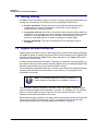
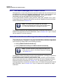
This is a Tip. It indicates useful or practical information.
This is a Note. It highlights important additional
information.
This is a Caution. It warns of situations that may result
in equipment malfunction or damage.
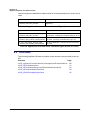
Acronyms and Abbreviations
12
APDU
Application Protocol Data Unit
API
Application Programming Interface
HA
Home Automation
SDK
Software Developer’s Kit
ZCL
ZigBee Cluster Library
© NXP Laboratories UK 2013
JN-UG-3076 v1.0
ZigBee Home Automation
User Guide
Related Documents
JN-UG-3048 ZigBee PRO Stack User Guide
JN-UG-3077 ZigBee Cluster Library User Guide
JN-UG-3075 JenOS User Guide
JN-UG-3064 SDK Installation and User Guide
JN-UG-3007 JN51xx Flash Programmer User Guide
JN-AN-1189 ZigBee Home Automation Demonstration Application Note
053520
ZigBee Home Automation Profile Specification [from ZigBee Alliance]
075123
ZigBee Cluster Library Specification [from ZigBee Alliance]
BS EN 50523 Household appliances interworking [from British Standards Institute]
Support Resources
To access online support resources such as SDKs, Application Notes and User
Guides, visit the Wireless Connectivity TechZone:
www.nxp.com/techzones/wireless-connectivity
All NXP resources referred to in this manual can be found at the above address,
unless otherwise stated.
Trademarks
All trademarks are the property of their respective owners.
Chip Compatibility
The software described in this manual can be used on the following NXP wireless
microcontrollers:
JN516x (currently only JN5168-001)
JN-UG-3076 v1.0
© NXP Laboratories UK 2013
13
About this Manual
14
© NXP Laboratories UK 2013
JN-UG-3076 v1.0
ZigBee Home Automation
User Guide
Part I:
Concept and Development
Information
JN-UG-3076 v1.0
© NXP Laboratories UK 2013
15
16
© NXP Laboratories UK 2013
JN-UG-3076 v1.0
ZigBee Home Automation
User Guide
1. Introduction to Home Automation
Home automation is not new! Throughout history, we have continuously strived to
automate tasks in the home in order to make our lives easier. Technology has now
advanced to the point at which we wish to take an integrated approach to home
automation, allowing appliances to communicate with each other and to be controlled
in flexible ways. A wireless network approach to this communication and control
provides an easy, cost-effective and scalable solution to home automation.
1.1 Wireless Home Automation
A network approach to home automation allows a diverse range of potential
applications, including:
Lighting
Heating and cooling
Shades, blinds and curtains
Home security
Possible application areas of home automation are described in Section 1.3.
Multiple home automation applications can be controlled through the same network
infrastructure. However, the installation of a wired home automation network is costly
and disruptive unless carried out during the construction or refurbishment of the
building. The advantages of a radio-based wireless home automation network are:
No expensive and disruptive network wiring to be installed in the building
Can be easily and cheaply installed at any time with minimal disruption
Can be expanded, as required, at any time to cover a wider physical area
Can be scaled, as required, at any time to incorporate more application areas
The ZigBee Home Automation (HA) application profile, described in this manual,
facilitates this wireless networking solution.
Note: Not all of the application areas covered by the
ZigBee Home Automation profile are currently
supported by the HA profile from NXP - see Section 1.3.
JN-UG-3076 v1.0
© NXP Laboratories UK 2013
17
Chapter 1
Introduction to Home Automation
1.2 Home Automation Benefits
Home automation brings a variety of benefits, depending on the application area(s).
These potential benefits include:
Easier lifestyle
Convenience of flexible control and remote control
Increased safety around the home
Improved security of the home
Energy savings with associated cost savings and environmental benefits
The energy saving features of home automation are outlined in Section 1.4.
1.3 Home Automation Application Areas
Home automation solutions can be applied to many aspects of the home, as described
in the sub-sections below.
Note: Not all of the application areas described below
are currently supported by the ZigBee Home
Automation (HA) profile from NXP.
1.3.1 Lighting
Lighting systems can be implemented with the following functionality:
Control lights from various points, including wall-switches, occupancy sensors,
remote control units, smartphones, tablets and computers
Control lights in terms of brightness and colour (for colour lamps)
Control a pre-defined group of lights by a single action
Definition of brightness and/or colour settings for one or more lights, forming a
‘scene’ for mood lighting
Lighting solutions are supported by NXP’s ZigBee HA profile.
Note: For a pure lighting system (with no other HA
application areas), the ZigBee Light Link (ZLL) profile
provides an alternative to the Home Automation profile.
For details of NXP’s ZLL profile, refer to the ZigBee
Light Link User Guide (JN-UG-3091).
18
© NXP Laboratories UK 2013
JN-UG-3076 v1.0
ZigBee Home Automation
User Guide
1.3.2 Heating, Ventilation and Air-Conditioning (HVAC)
HVAC systems can be implemented with the following functionality:
Control heating and/or air-conditioning from various points, including wallmounted control units, thermostats, occupancy sensors, remote control units,
smartphones, tablets and computers
Control the heating and/or air-conditioning in individual rooms according to their
use and/or occupancy
Control a pre-defined group of heaters or fans by a single action
Definition of heating/cooling settings (e.g. temperatures) for one or more
rooms, forming a ‘scene’
HVAC solutions are not currently supported by NXP’s ZigBee HA profile.
1.3.3 Shades and Window Coverings
The control of shades and window coverings (blinds and curtains) can be
implemented with the following functionality:
Control shades and window coverings from various points, including wallmounted control units, remote control units, smartphones, tablets and
computers
Open/close shades and window coverings, including partial opening/closing
Control a pre-defined group of shades or window coverings by a single action
Definition of open/close settings for one or more shades or window coverings,
forming a ‘scene’
Shade and window covering solutions are not currently supported by NXP’s ZigBee
HA profile.
1.3.4 Security Systems
Security systems (intruder and fire) can be implemented with the following
functionality:
Control the security system from various points, including wall-mounted control
units, remote control units, smartphones, tablets and computer
Control a pre-defined group of security sensors or door locks by a single action
Definition of security settings for one or more sensors or door-locks, forming a
‘scene’
Security systems are not currently supported by NXP’s ZigBee HA profile, except door
locks which are supported.
JN-UG-3076 v1.0
© NXP Laboratories UK 2013
19
Chapter 1
Introduction to Home Automation
1.4 Energy Saving
A ZigBee Home Automation system can result in energy saving and associated cost
savings for a household. The following may be employed to achieve this:
Scenes and timers: Energy savings can be achieved through the careful
configuration of ‘scenes’ and timers to ensure that no more energy is
consumed than is actually needed.
Occupancy sensors: Infra-red or movement sensors can be used to switch on
appliances, such as lights, only when a person is detected (and switch off when
a person is no longer detected). As an example, this method may be very
useful for controlling lights in a corridor or garage, or outside lights.
Energy monitoring: The power consumption of an HA system may be
monitored.
1.5 ZigBee Wireless Networks
ZigBee Home Automation (HA) is a public application profile that has been devised by
the ZigBee Alliance to support home automation solutions based on the ZigBee PRO
wireless network protocol. ZigBee PRO is fully described in the ZigBee PRO Stack
User Guide (JN-UG-3048).
A Mesh network topology is employed. Therefore, for maximum routing flexibility, all
the network nodes of an HA system should be ZigBee Routers (although ZigBee End
Devices are permitted, they cannot perform Mesh routing).
The manufacturer application that runs on an HA node provides the interface between
the HA profile software and the hardware of the node (e.g. the physical switch
mechanism of a lamp).
Note: The software architecture for HA, in terms of a
protocol stack, is described in more detail in Section 1.6.
The HA profile contains a number of ‘devices’, which are ZigBee software entities
used to implement particular functionality on a node - for example, the ‘On/Off Light’
device is used to switch a lamp on and off. The set of devices used in a node
determines the total functionality of the node.
Each HA device uses a number of clusters, where most clusters used in the HA profile
come from the ZigBee Cluster Library (ZCL). Complete lists of the devices and
associated clusters used by the HA profile are provided in Chapter 2.
20
© NXP Laboratories UK 2013
JN-UG-3076 v1.0
ZigBee Home Automation
User Guide
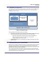
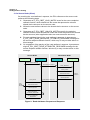
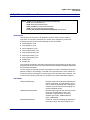
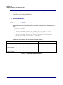
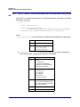
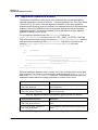
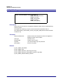
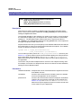
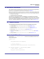
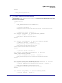
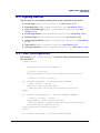
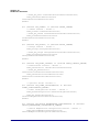
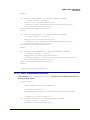
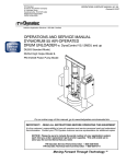
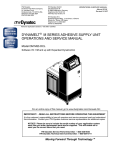
1.6 Software Architecture
The ZigBee Home Automation profile operates in conjunction with the ZigBee PRO
wireless network protocol. The software stack which runs on each HA node is
illustrated in Figure 1 below.
Application
HA Profile
ZCL and extensions
Manufacturer-specific
extensions
Green Power
Profile
ZigBee PRO stack layers
IEEE 802.15.4 MAC and PHY layers
Figure 1: HA Software Stack
The main features of the above stack are as follows:
Manufacturer application, which interfaces to the underlying ZigBee PRO stack
layers and controls the appliance hardware of the node, and uses:
HA profile, including ZCL resources (ZCL clusters and extensions)
Optional manufacturer-specific extensions to the HA profile
Optional ZigBee Green Power profile
ZigBee PRO stack layers, as described in the ZigBee PRO Stack User Guide
(JN-UG-3048)
1.7 Interoperability and Certification
ZigBee Home Automation provides a framework of interoperability between products
from different manufacturers. This is formalised through an HA certification and
compliance programme, in which completed products are tested for compliance to the
HA profile and, if successful, are HA certified.
Thus, a product developed and certified to the HA profile will be able operate with
other certified products in a HA system, irrespective of their manufacturers. This is an
important feature for the consumer market.
JN-UG-3076 v1.0
© NXP Laboratories UK 2013
21
Chapter 1
Introduction to Home Automation
In addition, the HA profile is designed to be interoperable at the network layer with
other public ZigBee application profiles.
1.8 Commissioning
The process of introducing an HA device into an HA network is called commissioning.
This involves finding an HA network, joining the network and ultimately binding an
endpoint on the new device to a compatible endpoint on an existing device, in order
to allow the new device to perform its function within the network (e.g. pairing a new
light-switch with an existing lamp so that the switch can control the lamp).
The HA software solution from NXP currently supports E-mode commissioning
(defined in the Home Automation Specification 1.1). It is a ZigBee requirement that all
HA devices support this mode of commissioning.
In E-mode commissioning, an HA device is commissioned by means of user
interactions, such as button-presses, on the physical devices or a remote control unit.
This commissioning mode does allow some automatic behaviour, such as
automatically joining a network at power-up, but some user intervention will always be
required to complete the commissioning process.
An E-mode commissioning module is provided in the NXP HA software and is
described in Chapter 10.
Note: ZigBee specify the commissioning terminology
that should be used by all HA product documentation in
order to ensure consistency between products and
manufacturers. This recommended terminology is listed
and described in Appendix B.
1.9 Internet Connectivity
ZigBee Home Automation offers the possibility of controlling the appliances in an HA
system via the Internet. Thus, this control can be performed from any Internetconnected device (PC, tablet, smartphone) located anywhere in the World (e.g. while
on holiday in another country).
Note: Internet connectivity is a feature of HA that is not
currently supported by NXP.
Access from the Internet requires the HA system to include an IP router or gateway
(connected to the Internet) as one of the network nodes.
In addition to the real-time control of an HA system over the Internet, the system could
also be configured from a device on the Internet (e.g. groups, scenes and timers).
22
© NXP Laboratories UK 2013
JN-UG-3076 v1.0
ZigBee Home Automation
User Guide
2. Home Automation (HA) Profile
Home Automation (HA) is ZigBee application profile 0x0104. This chapter details the
ZigBee devices available in the HA profile and the clusters that they use.
Note: This manual assumes that you are already
familiar with ZigBee PRO concepts such as endpoints,
profiles, clusters and attributes. For more information,
refer to the ZigBee PRO Stack User Guide
(JN-UG-3048), available from the NXP Wireless
Connectivity TechZone.
2.1 HA Devices
This manual covers the following devices from the ZigBee Home Automation
application profile, which are divided into application-oriented categories:
Generic devices (described in Section 2.3)
On/Off Switch
On/Off Output
Remote Control
Door Lock
Door Lock Controller
Simple Sensor
Lighting devices (described in Section 2.4)
On/Off Light
Dimmable Light
Colour Dimmable Light
On/Off Light Switch
Dimmer Switch
Colour Dimmer Switch
Light Sensor
Occupancy Sensor
The HA profile contains many other devices that are not currently implemented in the
NXP HA software - for the full list of HA devices, refer to the ZigBee Home Automation
Profile Specification (053520), available from the ZigBee Alliance (www.zigbee.org).
JN-UG-3076 v1.0
© NXP Laboratories UK 2013
23
Chapter 2
Home Automation (HA) Profile
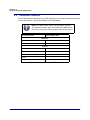
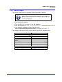
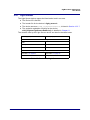
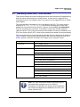
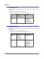
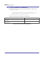
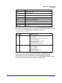
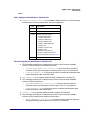
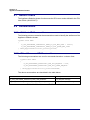
2.2 Common Clusters
The HA devices are defined by the clusters that they use. Some clusters are common
to most HA devices - these are detailed in the table below.
Note: For each device, there are mandatory clusters
and optional clusters. Also, the clusters are different for
the server (input) and client (output) sides of the device.
Server (Input) Side
Client (Output) Side
Mandatory
Basic
Identify
Optional
Clusters with reporting capability
Clusters with reporting capability
Power Configuration
Device Temperature Configuration
Alarms
Manufacturer-specific
Manufacturer-specific
Table 1: Common Clusters for HA Devices
24
© NXP Laboratories UK 2013
JN-UG-3076 v1.0
ZigBee Home Automation
User Guide
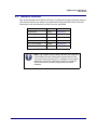
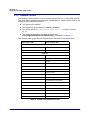
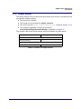
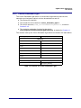
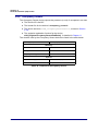
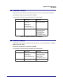
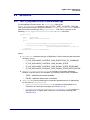
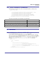
2.3 Generic Devices
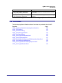
This section details the HA Generic Devices, including the clusters that they support.
The Generic Devices are listed in the table below along with their Device IDs and
references to the sub-sections in which they are described.
Generic Device
Device ID
Reference
On/Off Switch
0x0000
Section 2.3.1
On/Off Output
0x0002
Section 2.3.2
Remote Control
0x0006
Section 2.3.3
Door Lock
0x000A
Section 2.3.4
Door Lock Controller
0x000B
Section 2.3.5
Simple Sensor
0x000C
Section 2.3.6
Table 2: Generic Devices
Note: The clusters used by these devices are contained
in the ZigBee Cluster Library and are described in the
ZCL User Guide (JN-UG-3077), available from the NXP
Wireless Connectivity TechZone. However, not all the
listed clusters are currently supported by the NXP
software.
JN-UG-3076 v1.0
© NXP Laboratories UK 2013
25
Chapter 2
Home Automation (HA) Profile
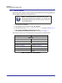
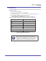
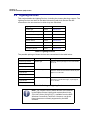
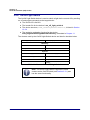
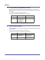
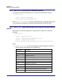
2.3.1 On/Off Switch
The On/Off Switch device is used to switch another device on and off by sending on,
off and toggle commands to the target device.
Note: This device should be used only when a more
specific device profile is not available - for example, the
On/Off Light Switch device should be used to control the
On/Off Light device.
The Device ID is 0x0000
The header file for the device is on_off_switch.h
The device structure, tsHA_OnOffSwitchDevice, is listed in Section 12.1.1
The endpoint registration function for the device,
eHA_RegisterOnOffSwitchEndPoint(), is detailed in Chapter 11
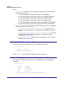
The clusters used by the On/Off Switch device are listed in the table below.
Server (Input) Side
Client (Output) Side
Mandatory
Basic
On/Off (subject to binding)
Identify
Optional
See Table 1 on page 24
See Table 1 on page 24
On/Off Switch Configuration
Scenes
Groups
Identify
Table 3: Clusters for On/Off Switch
26
© NXP Laboratories UK 2013
JN-UG-3076 v1.0
ZigBee Home Automation
User Guide
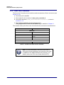
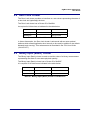
2.3.2 On/Off Output
The On/Off Output device is capable of being switched on and off.
Note: This device should be used only when a more
specific device profile is not available - for example, the
On/Off Light device.
The Device ID is 0x0002
The header file for the device is on_off_output.h
The device structure, tsHA_OnOffOutputDevice, is listed in Section 12.1.2
The endpoint registration function for the device,
eHA_RegisterOnOffOutputEndPoint(), is detailed in Chapter 11
The clusters used by the On/Off Output device are listed in the table below.
Server (Input) Side
Client (Output) Side
Mandatory
Basic
Identify
On/Off
Scenes
Groups
Optional
See Table 1 on page 24
See Table 1 on page 24
Table 4: Clusters for On/Off Output
JN-UG-3076 v1.0
© NXP Laboratories UK 2013
27
Chapter 2
Home Automation (HA) Profile
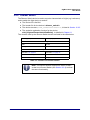
2.3.3 Remote Control
The Remote Control device is used to control and monitor one or more other devices.
The client side is typically incorporated in a handheld unit, with the server side in the
node(s) to be controlled/monitored.
The Device ID is 0x0006
The header file for the device is remote_control.h
The device structure, tsHA_RemoteControlDevice, is listed in Section
12.1.3
The endpoint registration function for the device,
eHA_RegisterRemoteControlEndPoint(), is detailed in Chapter 11
The clusters used by the Remote Control device are listed in the table below.
Server (Input) Side
Client (Output) Side
Mandatory
Basic
At least one optional cluster
Identify
Optional
See Table 1 on page 24
See Table 1 on page 24
Identify
On/Off
Level Control
Groups
Scenes
Colour Control
Pump Configuration and Control
Shade Configuration
On/Off Switch Configuration
Temperature Measurement
Illuminance Level Sensing
Illuminance Measurement
Window Covering
Door Lock
Thermostat
Table 5: Clusters for Remote Control
28
© NXP Laboratories UK 2013
JN-UG-3076 v1.0
ZigBee Home Automation
User Guide
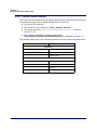
2.3.4 Door Lock
The Door Lock device is able to receive commands from a Door Lock Controller device
(see Section 2.3.5).
The Device ID is 0x000A
The header file for the device is door_lock.h
The device structure, tsHA_DoorLockDevice, is listed in Section 12.1.4
The endpoint registration function for the device,
eHA_RegisterDoorLockEndPoint(), is detailed in Chapter 11
The clusters used by the Door Lock device are listed in the table below.
Server (Input) Side
Client (Output) Side
Mandatory
Basic
Identify
Door Lock
Scenes
Groups
Optional
See Table 1 on page 24
See Table 1 on page 24
Table 6: Clusters for Door Lock
Note: In Home Automation, the Door Lock cluster is
enhanced to allow Application-level security to be used
(in addition to the default Network-level security). For
details, refer to the ZCL User Guide (JN-UG-3077).
JN-UG-3076 v1.0
© NXP Laboratories UK 2013
29
Chapter 2
Home Automation (HA) Profile
2.3.5 Door Lock Controller
The Door Lock Controller device is able to send commands to a Door Lock device (see
Section 2.3.4).
The Device ID is 0x000B
The header file for the device is door_lock_controller.h
The device structure, tsHA_DoorLockControllerDevice, is listed in
Section 12.1.5
The endpoint registration function for the device,
eHA_RegisterDoorLockControllerEndPoint(), is detailed in Chapter 11
The clusters used by the Door Lock Controller device are listed in the table below.
Server (Input) Side
Client (Output) Side
Mandatory
Basic
Door Lock
Identify
Scenes
Group
Identify
Optional
See Table 1 on page 24
See Table 1 on page 24
Table 7: Clusters for Door Lock Controller
Note: In Home Automation, the Door Lock cluster is
enhanced to allow Application-level security to be used
(in addition to the default Network-level security). For
details, refer to the ZCL User Guide (JN-UG-3077).
30
© NXP Laboratories UK 2013
JN-UG-3076 v1.0
ZigBee Home Automation
User Guide
2.3.6 Simple Sensor
The Simple Sensor device is able to accept a binary input from an on/off device such
as magnetic window contacts.
The Device ID is 0x000C
The header file for the device is simple_sensor.h
The device structure, tsHA_SimpleSensorDevice, is listed in Section 12.1.6
The endpoint registration function for the device,
eHA_RegisterSimpleSensorEndPoint(), is detailed in Chapter 11
The clusters used by the Simple Sensor device are listed in the table below.
Server (Input) Side
Client (Output) Side
Mandatory
Binary Input (Basic)
Optional
Table 8: Clusters for Simple Sensor
JN-UG-3076 v1.0
© NXP Laboratories UK 2013
31
Chapter 2
Home Automation (HA) Profile
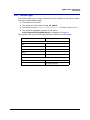
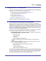
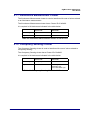
2.4 Lighting Devices
This section details the Lighting Devices, including the clusters that they support. The
Lighting Devices are listed in the table below along with their Device IDs and
references to the sub-sections in which they are described.
Lighting Device
Device ID
Reference
On/Off Light
0x0100
Section 2.4.1
Dimmable Light
0x0101
Section 2.4.2
Colour Dimmable Light
0x0102
Section 2.4.3
On/Off Light Switch
0x0103
Section 2.4.4
Dimmer Switch
0x0104
Section 2.4.5
Colour Dimmer Switch
0x0105
Section 2.4.6
Light Sensor
0x0106
Section 2.4.7
Occupancy Sensor
0x0107
Section 2.4.8
Table 9: Lighting Devices
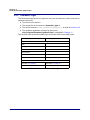
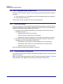
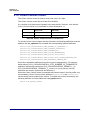
The possible pairings of these devices are summarised in the table below:
Controller Device
Controlled Device
Description
On/Off Light Switch
On/Off Light
Switch or sensor puts light in one of two states,
on or off
Dimmable Light
Switch or sensor controls luminance of light
between maximum and minimum levels, or puts
light in on or off state
Colour Dimmable Light
Switch or sensor controls hue, saturation and
luminance of multi-colour light, or puts light in
on or off state
Light Sensor
Occupancy Sensor
Dimmer Switch
Light Sensor
Occupancy Sensor
Colour Dimmer Switch
Light Sensor
Occupancy Sensor
Table 10: Pairings of Lighting Devices
Note: The clusters used by these devices are contained
in the ZigBee Cluster Library and are described in the
ZCL User Guide (JN-UG-3077), available from the NXP
Wireless Connectivity TechZone. However, not all the
listed clusters are currently supported by the NXP
software.
32
© NXP Laboratories UK 2013
JN-UG-3076 v1.0
ZigBee Home Automation
User Guide
2.4.1 On/Off Light
The On/Off Light device is simply a light that can be switched on and off (two states
only and no intermediate levels).
The Device ID is 0x0100
The header file for the device is on_off_light.h
The device structure, tsHA_OnOffLightDevice, is listed in Section 12.2.1
The endpoint registration function for the device,
eHA_RegisterOnOffLightEndPoint(), is detailed in Chapter 11
The clusters used by the On/Off Light device are listed in the table below.
Server (Input) Side
Client (Output) Side
Mandatory
Basic
Identify
On/Off
Scenes
Groups
Optional
See Table 1 on page 24
See Table 1 on page 24
Occupancy Sensing
Table 11: Clusters for On/Off Light
JN-UG-3076 v1.0
© NXP Laboratories UK 2013
33
Chapter 2
Home Automation (HA) Profile
2.4.2 Dimmable Light
The Dimmable Light device is a light that can have its luminance varied, and can be
switched on and off.
The Device ID is 0x0101
The header file for the device is dimmable_light.h
The device structure, tsHA_DimmableLightDevice, is listed in Section 2.4.2
The endpoint registration function for the device,
eHA_RegisterDimmableLightEndPoint(), is detailed in Chapter 11
The clusters used by the Dimmable Light device are listed in the table below.
Server (Input) Side
Client (Output) Side
Mandatory
Basic
Identify
On/Off
Level Control
Scenes
Groups
Optional
See Table 1 on page 24
See Table 1 on page 24
Occupancy Sensing
Table 12: Clusters for Dimmable Light
34
© NXP Laboratories UK 2013
JN-UG-3076 v1.0
ZigBee Home Automation
User Guide
2.4.3 Colour Dimmable Light
The Colour Dimmable Light device is a multi-colour light that can have its hue,
saturation and luminance varied, and can be switched on and off.
The Device ID is 0x0102
The header file for the device is colour_dimmable_light.h
The device structure, tsHA_ColourDimmableLightDevice, is listed in
Section 2.4.3
The endpoint registration function for the device,
eHA_RegisterColourDimmableLightEndPoint(), is detailed in Chapter 11
The clusters used by the Colour Dimmable Light device are listed in the table below.
Server (Input) Side
Client (Output) Side
Mandatory
Basic
Identify
On/Off
Level Control
Colour Control
Scenes
Groups
Optional
See Table 1 on page 24
See Table 1 on page 24
Occupancy Sensing
Table 13: Clusters for Colour Dimmable Light
JN-UG-3076 v1.0
© NXP Laboratories UK 2013
35
Chapter 2
Home Automation (HA) Profile
2.4.4 On/Off Light Switch
The On/Off Light Switch device is used to switch a light device on and off by sending
on, off and toggle commands to the target device.
The Device ID is 0x0103
The header file for the device is on_off_light_switch.h
The device structure, tsHA_OnOffLightSwitchDevice, is listed in Section
12.2.4
The endpoint registration function for the device,
eHA_RegisterOnOffLightSwitchEndPoint(), is detailed in Chapter 11
The clusters used by the On/Off Light Switch device are listed in the table below.
Server (Input) Side
Client (Output) Side
Mandatory
Basic
On/Off
Identify
Optional
See Table 1 on page 24
See Table 1 on page 24
On/Off Switch Configuration
Scenes
Groups
Identify
Table 14: Clusters for On/Off Light Switch
Note: The On/Off Light Switch supports the same
clusters as the On/Off Switch (see Section 2.3.1) and
has the same functionality.
36
© NXP Laboratories UK 2013
JN-UG-3076 v1.0
ZigBee Home Automation
User Guide
2.4.5 Dimmer Switch
The Dimmer Switch device is used to control a characteristic of a light (e.g. luminance)
and to switch the light device on and off.
The Device ID is 0x0104
The header file for the device is dimmer_switch.h
The device structure, tsHA_DimmerSwitchDevice, is listed in Section 12.2.5
The endpoint registration function for the device,
eHA_RegisterDimmerSwitchEndPoint(), is detailed in Chapter 11
The clusters used by the Dimmer Switch device are listed in the table below.
Server (Input) Side
Client (Output) Side
Mandatory
Basic
On/Off
Identify
Level Control
Optional
See Table 1 on page 24
See Table 1 on page 24
On/Off Switch Configuration
Scenes
Groups
Table 15: Clusters for Dimmer Switch
Note: The Dimmer Switch supports the same clusters
as the Level Control Switch (see Section 2.3.2) and has
the same functionality.
JN-UG-3076 v1.0
© NXP Laboratories UK 2013
37
Chapter 2
Home Automation (HA) Profile
2.4.6 Colour Dimmer Switch
The Colour Dimmer Switch device is used to control the hue, saturation and luminance
of a multi-colour light, and to switch the light device on and off.
The Device ID is 0x0105
The header file for the device is colour_dimmer_switch.h
The device structure, tsHA_ColourDimmerSwitchDevice, is listed in
Section 12.2.6
The endpoint registration function for the device,
eHA_RegisterColourDimmerSwitchEndPoint(), is detailed in Chapter 11
The clusters used by the Colour Dimmer Switch device are listed in the table below.
Server (Input) Side
Client (Output) Side
Mandatory
Basic
On/Off
Identify
Level Control
Colour Control
Optional
See Table 1 on page 24
See Table 1 on page 24
On/Off Switch Configuration
Scenes
Groups
Identify
Table 16: Clusters for Colour Dimmer Switch
38
© NXP Laboratories UK 2013
JN-UG-3076 v1.0
ZigBee Home Automation
User Guide
2.4.7 Light Sensor
The Light Sensor device reports the illumination level in an area.
The Device ID is 0x0106
The header file for the device is light_sensor.h
The device structure, tsHA_LightSensorDevice, is listed in Section 12.2.7
The endpoint registration function for the device,
eHA_RegisterLightSensorEndPoint(), is detailed in Chapter 11
The clusters used by the Light Sensor device are listed in the table below.
Server (Input) Side
Client (Output) Side
Mandatory
Basic
Identify
Illuminance Measurement
Optional
See Table 1 on page 24
See Table 1 on page 24
Groups
Table 17: Clusters for Light Sensor
JN-UG-3076 v1.0
© NXP Laboratories UK 2013
39
Chapter 2
Home Automation (HA) Profile
2.4.8 Occupancy Sensor
The Occupancy Sensor device reports the presence (or not) of occupants in an area.
The Device ID is 0x0107
The header file for the device is occupancy_sensor.h
The device structure, tsHA_OccupancySensorDevice, is listed in Section
2.4.8
The endpoint registration function for the device,
eHA_RegisterOccupancySensorEndPoint(), is detailed in Chapter 11
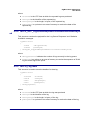
The clusters used by the Occupancy Sensor device are listed in the table below.
Server (Input) Side
Client (Output) Side
Mandatory
Basic
Identify
Occupancy Sensing
Optional
See Table 1 on page 24
See Table 1 on page 24
Groups
Table 18: Clusters for Occupancy Sensor
40
© NXP Laboratories UK 2013
JN-UG-3076 v1.0
ZigBee Home Automation
User Guide
3. HA Application Development
This chapter provides basic guidance on developing a ZigBee Home Automation (HA)
application. The topics covered in this chapter include:
Development resources and their installation (Section 3.1)
HA programming resources (Section 3.2)
API functions (Section 3.3)
Development phases (Section 3.4)
Building an application (Section 3.5)
Application coding is described separately in Chapter 4.
3.1 Development Resources and Installation
NXP provide a wide range of resources to aid in the development of ZigBee HA
applications for the JN5168 wireless microcontroller. An HA application is developed
as a ZigBee PRO application that uses the NXP ZigBee PRO APIs in conjunction with
JenOS (Jennic Operating System), together with HA-specific and ZCL resources. All
resources are available from the NXP Wireless Connectivity TechZone (see “Support
Resources” on page 13) and are outlined below.
The resources for developing a ZigBee HA application are supplied free-of-charge in
a Software Developer’s Kit (SDK), which is provided as two installers:
HA SDK (JN-SW-4067): This installer contains the ZigBee PRO stack and HA
profile software, including a number of C APIs:
HA and ZCL APIs
ZigBee PRO APIs
JenOS APIs
JN516x Integrated Peripherals API
In addition, the ZPS and JenOS Configuration Editors are provided in this
installer.
SDK Toolchain (JN-SW-4041): This installer contains the tools that you will
use in creating an application, including:
Eclipse IDE (Integrated Development Environment)
JN51xx compiler
JN51xx Flash Programmer
Cygwin Command Line Interface (CLI)
For full details of the SDK and installation instructions, refer to the SDK Installation and
User Guide (JN-UG-3064). The SDK is normally installed into the directory C:/Jennic.
An HA demonstration application is provided in the Application Note ZigBee Home
Automation Demonstration (JN-AN-1189), available from NXP.
JN-UG-3076 v1.0
© NXP Laboratories UK 2013
41
Chapter 3
HA Application Development
3.2 HA Programming Resources
The NXP HA API contains a range of resources (such as functions and structures),
including:
Core resources (e.g. for initialising the API and registering device endpoints)
Cluster-specific resources
These resources are introduced in the sub-sections below.
3.2.1 Core Resources
The core resources of the HA profile handle the basic operations required in an HA
network, irrespective of the clusters used. Some of these resources are provided in
the HA API and some are provided in the ZCL API.
Functions for the following operations are provided in the HA API and are
detailed in Chapter 11:
Initialising the HA API (one function)
Servicing timing requirements (one function)
Registering a device endpoint on an HA node (one function per device)
Functions for the following operations are provided in the ZCL API and are
detailed in the ZCL User Guide (JN-UG-3077):
Requesting a read access to cluster attributes on a remote device
Requesting a write access to cluster attributes on a remote device
Handling events on an HA device
Use of the above functions is described in Chapter 4.
3.2.2 Cluster-specific Resources
An HA device uses certain mandatory and optional ZigBee clusters, as listed for each
device in Chapter 2.
Many of these clusters are taken from the ZCL and introduced in Chapter 5. They are
fully described in the ZigBee Cluster Library User Guide (JN-UG-3077).
42
© NXP Laboratories UK 2013
JN-UG-3076 v1.0
ZigBee Home Automation
User Guide
3.3 Function Prefixes
The API functions used in HA are categorised and prefixed in the following ways:
HA functions: Used to interact with the HA profile and prefixed with xHA_
ZCL functions: Used to interact with the ZCL and prefixed with xZCL_
Cluster functions: Used to interact with clusters and prefixed as follows:
For clusters defined in the HA specification, they are prefixed with xHA_
For clusters defined in the ZCL specification, they are prefixed with xCLD_
In the above prefixes, x represents one or more characters that indicate the return
type, e.g. “v” for void.
Only functions that are HA-specific are detailed in this manual. Functions which relate
to clusters of the ZCL are detailed in the ZCL User Guide (JN-UG-3077).
3.4 Development Phases
The main phases of development for an HA application are the same as for any
ZigBee PRO application, and are outlined below.
Note: Before starting your HA application development,
you should familiarise yourself with the general aspects
of ZigBee PRO application development, described in
the ZigBee PRO Stack User Guide (JN-UG-3048).
1. Network Configuration: Configure the ZigBee network parameters for the
nodes using the ZPS Configuration Editor - refer to the ZigBee PRO Stack
User Guide (JN-UG-3048).
2. OS Configuration: Configure the JenOS resources to be used by your
application using the JenOS Configuration Editor - refer to the JenOS User
Guide (JN-UG-3075).
3. Application Code Development: Develop the application code for your
nodes using the ZigBee PRO APIs, JenOS APIs, HA API and ZCL - refer to
the ZigBee PRO Stack User Guide (JN-UG-3048), JenOS User Guide
(JN-UG-3075) and ZCL User Guide (JN-UG-3077), as well as this manual.
4. Application Build: Build the application binaries for your nodes using the
JN51xx compiler and linker built into the Eclipse platform - refer to Section 3.5
and to the SDK Installation and User Guide (JN-UG-3064).
5. Node Programming: Load the application binaries into Flash memory on
your nodes using the JN51xx Flash programmer, which can be launched
either from within Eclipse or directly, and is described in the JN51xx Flash
Programmer User Guide (JN-UG-3007).
JN-UG-3076 v1.0
© NXP Laboratories UK 2013
43
Chapter 3
HA Application Development
3.5 Building an Application
This section outlines how to build an HA application developed for the JN5168 device.
First of all, the configuration of compile-time options and ZigBee network parameters
is described, and then directions are given for building and loading the application.
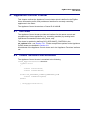
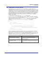
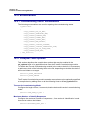
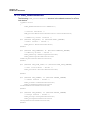
3.5.1 Compile-Time Options
Before the application can be built, the HA compile-time options must be configured in
the header file zcl_options.h for the application. This header file is supplied in the
Application Note ZigBee Home Automation Demonstration (JN-AN-1189), which can
be used as a template.
Number of Endpoints
The highest numbered endpoint used by the HA application must be specified - for
example:
#define HA_NUMBER_OF_ENDPOINTS
3
Normally, the endpoints starting at endpoint 1 will be used for HA, so in the above case
endpoints 1 to 3 will be used for HA. It is possible, however, to use the lower numbered
endpoints for non-HA purposes, e.g. to run other protocols on endpoints 1 and 2, and
HA on endpoint 3. In this case, with HA_NUMBER_OF_ENDPOINTS set to 3, some
storage will be statically allocated by HA for endpoints 1 and 2 but never used. Note
that this define applies only to local endpoints - the application can refer to remote
endpoints with numbers beyond the locally defined value of
HA_NUMBER_OF_ENDPOINTS.
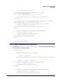
Enabled Clusters
All required clusters must be enabled in the options header file. For example, an
application for an On/Off Light device that uses all the possible clusters will require the
following definitions:
#define CLD_BASIC
#define CLD_IDENTIFY
#define CLD_GROUPS
#define CLD_SCENES
#define CLD_ONOFF
Server and Client Options
Many clusters used in HA have options that indicate whether the cluster will act as a
server or a client on the local device. If the cluster has been enabled using one of the
above definitions, the server/client status of the cluster must be defined. For example,
to employ the Groups cluster as a server, include the following definition in the header
file:
#define GROUPS_SERVER
44
© NXP Laboratories UK 2013
JN-UG-3076 v1.0
ZigBee Home Automation
User Guide
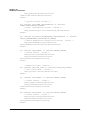
Support for Attribute Read/Write
Read/write access to cluster attributes must be explicitly compiled into the application,
and must be enabled separately for the server and client sides of a cluster using the
following macros in the options header file:
#define ZCL_ATTRIBUTE_READ_SERVER_SUPPORTED
#define ZCL_ATTRIBUTE_READ_CLIENT_SUPPORTED
#define ZCL_ATTRIBUTE_WRITE_SERVER_SUPPORTED
#define ZCL_ATTRIBUTE_WRITE_CLIENT_SUPPORTED
Note that each of the above definitions will apply to all clusters used in the application.
Optional Attributes
Many clusters have optional attributes that may be enabled at compile-time via the
options header file - for example, the Basic cluster ‘application version’ attribute is
enabled as follows:
#define CLD_BAS_ATTR_APPLICATION_VERSION
Note: Cluster-specific compile-time options are detailed
in the chapters for the individual clusters in Part II: HA
Clusters and Modules. For clusters from the ZCL, refer
to the ZCL User Guide (JN-UG-3077).
3.5.2 ZigBee Network Parameters
HA applications may require specific settings of certain ZigBee network parameters.
These parameters are set using the ZPS Configuration Editor. The full set of ZigBee
network parameters are detailed in the ZigBee PRO Stack User Guide (JN-UG-3048).
3.5.3 Building and Loading the Application Binary
An HA application for the JN5168 device is built like any other ZigBee PRO
application. The build is normally carried out using the Eclipse IDE. This is the method
that we recommend, although it is also possible to use makefiles directly from the
command line (Cygwin).
For instructions on building an application in the Eclipse IDE, refer to the SDK
Installation and User Guide (JN-UG-3064). This guide also indicates how to load the
built application binary file into a JN5168-based node using the JN51xx Flash
Programmer launched from within Eclipse. Alternatively, you can use the JN51xx
Flash Programmer directly. In either case, you will need to refer to the JN51xx Flash
Programmer User Guide (JN-UG-3007) as part of this procedure.
JN-UG-3076 v1.0
© NXP Laboratories UK 2013
45
Chapter 3
HA Application Development
46
© NXP Laboratories UK 2013
JN-UG-3076 v1.0
ZigBee Home Automation
User Guide
4. HA Application Coding
This chapter covers general aspects of HA application coding, including essential HA
programming concepts, code initialisation, callback functions, reading and writing
attributes, and event handling. Application coding that is particular to individual
clusters is described later, in the relevant cluster-specific chapter.
Note: ZCL API functions referenced in this chapter are
fully described in the ZCL User Guide (JN-UG-3077).
4.1 HA Programming Concepts
This section describes the essential programming concepts that are needed in HA
application development. The basic operations in a HA network are concerned with
reading and setting the attribute values of the clusters of a device.
4.1.1 Shared Device Structures
In each HA device, attribute values are exchanged between the application and the
HA library by means of a shared structure. This structure is protected by a mutex
(described in the ZCL User Guide (JN-UG-3077)). The structure for a particular HA
device contains structures for the clusters supported by that device (see Chapter 2).
The available device structures are provided in Chapter 12.
Note: In order to use a cluster which is supported by a
device, the relevant option for the cluster must be
specified at build-time - see Section 3.5.3.
A shared device structure may be used in either of the following ways:
The local application writes attribute values to the structure, allowing the
ZigBee Cluster Library (ZCL) to respond to commands relating to these
attributes.
The ZCL parses incoming commands that write attribute values to the
structure. The written values can then be read by the local application.
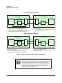
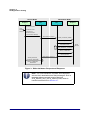
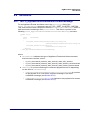
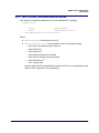
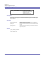
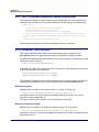
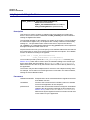
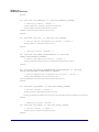
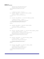
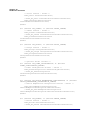
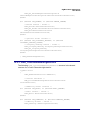
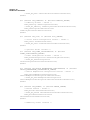
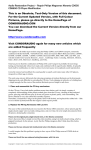
Remote read and write operations involving a shared device structure are illustrated
in Figure 1 below. For more detailed descriptions of these operations, refer to Section
4.5 and Section 4.6.
JN-UG-3076 v1.0
© NXP Laboratories UK 2013
47
Chapter 4
HA Application Coding
Reading Remote Attributes
Client Device
Server Device
Read
Command
Read Request
Application
Read
Device
Structure
(Copy)
ZCL
Write
ZCL
Read
Response
Device
Structure
Application
Write
Event (s)
2. If necessary, application first updates attribute values in
device structure.
3. ZCL reads requested attribute values from device structure
and then returns them to requesting client .
1. Application requests read of attribute values from device
structure on remote server and ZCL sends request .
4. ZCL receives response, writes received attribute values to
local copy of device structure and generates events (which
can prompt application to read attributes from structure ).
Writing Remote Attributes
Client Device
Server Device
Write
Command
Write Request
Application
Write
Device
Structure
(Copy)
ZCL
ZCL
Write
Read
Response
Device
Structure
Application
Read
Event (s)
1. Application writes new attribute values to local copy of device
structure for remote server.
2. ZCL sends 'write attributes' request to remote server.
5. ZCL can receive optional response and generate events
for the application (that indicate any unsuccessful writes).
3. ZCL writes received attribute values to device structure and
optionally sends response to client.
4. If required, application can then read new attribute values
from device structure.
Figure 1: Operations using Shared Device Structure
Note: Provided that there are no remote attribute writes,
the attributes of a cluster server (in the shared structure)
on a device are maintained by the local application(s).
The equivalent attributes of a cluster client on another
device are copies of these cluster server attributes
(remotely read from the server).
48
© NXP Laboratories UK 2013
JN-UG-3076 v1.0
ZigBee Home Automation
User Guide
4.1.2 Addressing
Communications between devices in an HA network are performed using standard
ZigBee PRO mechanisms. A brief summary is provided below.
In order to perform an operation (e.g. a read) on a remote node in a ZigBee PRO
network, a command must be sent from the relevant output (or client) cluster on the
local node to the relevant input (or server) cluster on the remote node.
At a higher level, an application (and therefore the HA device and supported clusters)
is associated with a unique endpoint, which acts as the I/O port for the application on
the node. Therefore, a command is sent from an endpoint on the local node to the
relevant endpoint(s) on the remote node.
The destination node(s) and endpoint(s) must be identified by the sending application.
The endpoints on each node are numbered from 1 to 240. The target node(s) can be
addressed in a number of different ways, listed below.
64-bit IEEE/MAC address
16-bit ZigBee network (short) address
16-bit group address, relating to a pre-specified group of nodes and endpoints
A binding, where the source endpoint has been pre-bound to the remote
node(s) and endpoint(s)
A broadcast, in which the message is sent to all nodes of a certain type, one of:
all Routers
all End Devices
only End Devices for which the radio receiver stays on when they are idle
A destination address structure, tsZCL_Address, is defined in the ZCL and is
detailed in the ZCL User Guide (JN-UG-3077). Enumerations are provided for the
addressing mode and broadcast mode in this structure, and are also detailed in the
above manual.
4.1.3 OS Resources
The HA library and ZCL require OS resources, such as tasks and mutexes. These
resources are provided by JenOS (Jennic Operating System), supplied in the HA
SDK.
The JenOS resources for an application are allocated using the JenOS Configuration
Editor, which is provided as an NXP-specific plug-in for the Eclipse IDE. Use of the
JenOS Configuration Editor for an HA application should be based on the HA
demonstration application (rather than on the standard ZigBee PRO stack template)
to ensure that the extra JenOS resources required by the HA profile and the ZCL are
available.
A JenOS mutex protects the shared structure that holds the cluster attribute values for
a device (see Section 4.1.1 above). The ZCL invokes an application callback function
to lock and unlock this mutex. The mutex should be used in conjunction with the
counting mutex code provided in the appendix of the ZCL User Guide (JN-UG-3077).
JN-UG-3076 v1.0
© NXP Laboratories UK 2013
49
Chapter 4
HA Application Coding
The software for this mutex operation is contained in the HA demonstration
application.
The task that the HA library and ZCL use to process incoming messages is defined in
the HA demonstration application. Callbacks from the HA library and ZCL to the
application will be in the context of this task. The HA demonstration application has a
separate task for the user application code. This task also links to the shared-structure
mutex in the JenOS configuration so that it can use critical sections to protect access
to the shared structures.
Only data events addressed to the correct ZigBee profile, endpoint and cluster are
processed by the ZCL, possibly with the aid of a callback function. Stack and data
events that are not addressed to an HA endpoint are handled by the application
through a callback function. All events are first passed into the ZCL using the function
vZCL_EventHandler(). The ZCL either processes the event or passes it to the
application, invoking the relevant callback function (refer to Section 4.3 for information
on callback functions and to Section 4.7 for more details on event handling).
If the ZCL consumes a data event, it will free the corresponding Protocol Data Unit
(PDU), otherwise it is the responsibility of the application to free the PDU.
4.2 Initialisation
An HA application is initialised like a normal ZigBee PRO application, as described in
the section “Forming a Network” of the ZigBee PRO Stack User Guide (JN-UG-3048),
except there is no need to explicitly start the ZigBee PRO stack using the function
ZPS_eAplZdoStartStack(). In addition, some HA initialisation must be performed in
the application code.
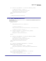
Initialisation of an HA application must be performed in the following places and order:
1. In the header file zcl_options.h, enable the required compile-time options.
These options include the clusters to be used by the device, the client/server
status of each cluster and the optional attributes for each cluster. For more
information on compile-time options, refer to Section 3.5.1.
2. In the application, create an instance of the device structure by declaring a file
scope variable - for example:
tsHA_DimmableLightDevice sDevice;
3. In the initialisation part of the application, set up the HA device(s) handled by
your code, as follows:
a) Set the initial values of the cluster attributes to be used by the device - for
example:
sDevice.sBasicCluster.u8StackVersion = 1;
sDevice.sBasicCluster....
These settings should appear in the code after JenOS has been started and
before the HA initialisation function is called (next step).
b) After calling ZPS_eAplAfInit(), call the HA initialisation function,
eHA_Initialise(). This function requires you to specify a user-defined
callback function for handling stack events (see Section 4.3), as well as a
50
© NXP Laboratories UK 2013
JN-UG-3076 v1.0
ZigBee Home Automation
User Guide
pool of APDUs (Application Protocol Data Units) for sending and receiving
data.
c) Register each device by calling the relevant device registration function for example, eHA_RegisterDimmableLightEndPoint(). In this function
call, the device must be allocated a unique endpoint (in the range 1-240).
In addition, its device structure must be specified as well as a user-defined
callback function that will be invoked by the HA library when an event
occurs relating to the endpoint (see Section 4.3). As soon as this function
has been called, the shared device structure can be read by another
device.
The device registration functions create instances of all the clusters used by the
device, so there is no need to explicitly call the individual cluster creation functions,
e.g. eCLD_IdentifyCreateIdentify() for the Identify cluster.
Note: The set of endpoint registration functions for the
different HA device types are detailed in Chapter 11.
4.3 Callback Functions
Two types of user-defined callback function must be provided (and registered as
described in Section 4.2):
Endpoint Callback Function: A callback function must be provided for each
endpoint used, where this callback function will be invoked when an event
occurs (such as an incoming message) relating to the endpoint. The callback
function is registered with the HA library when the endpoint is registered using
the registration function for the HA device type that the endpoint supports - for
example, using eHA_RegisterOnOffLightEndPoint() for an On/Off Light
device (see Chapter 11).
General Callback Function: Events that do not have an associated endpoint
are delivered via a callback function that is registered with the HA library
through the function eHA_Initialise(). For example, stack leave and join events
can be received by the application through this callback function.
The endpoint callback function and general callback function both have the type
definition given below:
typedef void (* tfpZCL_ZCLCallBackFunction)
(tsZCL_CallBackEvent *pCallBackEvent);
The callback events are detailed in the ZCL User Guide (JN-UG-3077) and event
handling is further described in Section 4.7.
JN-UG-3076 v1.0
© NXP Laboratories UK 2013
51
Chapter 4
HA Application Coding
4.4 Discovering Endpoints and Clusters
In order to communicate, a cluster client and cluster server must discover and store
each other’s contact details - that is, the address of the node and the number of the
endpoint on which the relevant cluster resides.
The HA application on a node can discover other nodes in the network by calling the
ZigBee PRO API function ZPS_eAplZdpMatchDescRequest(), which sends out a
match descriptor request (as a broadcast to all network nodes or as unicasts to
selected nodes). This function allows nodes to be selectively discovered by looking for
specific criteria in the Simple Descriptors of the endpoints on the recipient nodes.
These criteria include a list of required input (server) clusters and a list of required
output (client) clusters. In this way, an application which supports a particular cluster
server or client can discover its cluster counterpart(s) in the rest of the network.
If a recipient node satisfies the criteria specified in a match descriptor request, it will
respond with a match descriptor response. This response contains the network
address of the responding node and a list of the node’s endpoints that satisfy the
required criteria - for example, the endpoints that support the specified cluster(s).
Once a relevant node and endpoint have been identified:
The function ZPS_eAplZdpIeeeAddrRequest() can be used to obtain the
IEEE/MAC address of the node and then both addresses can be added to the
local Address Map using the function ZPS_eAplZdoAddAddrMapEntry().
If data packets between the two endpoints are to be encrypted by means of
standard ZigBee PRO security then one of the two nodes must initiate a link
key request using the function ZPS_eAplZdoRequestKeyReq().
The node can bind a local endpoint to the remote endpoint using the function
ZPS_eAplZdpBindUnbindRequest().
Note: All of the above functions are described in the
ZigBee PRO Stack User Guide (JN-UG-3048).
52
© NXP Laboratories UK 2013
JN-UG-3076 v1.0
ZigBee Home Automation
User Guide
4.5 Reading Attributes
Attributes can be read using a general ZCL function, or using an HA or ZCL function
which is specific to the target cluster. The cluster-specific functions for reading
attributes are covered in the chapters of this manual that describe the supported
clusters or in the ZCL User Guide (JN-UG-3077). Note that read access to cluster
attributes must be explicitly enabled at compile-time as described in Section 3.5.1.
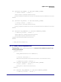
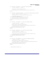
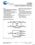
The remainder of this section describes the use of the ZCL function
eZCL_SendReadAttributesRequest() to send a ‘read attributes’ request, although
the sequence is similar when using the cluster-specific ‘read attributes’ functions. The
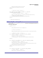
resulting activities on the source and destination nodes are outlined below and
illustrated in Figure 2. Note that instances of the shared device structure (which
contains the relevant attributes) exist on both the source and destination nodes. The
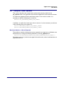
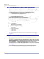
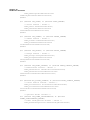
events generated from a ‘read attributes’ request are further described in Section 4.7.
1. On Source Node (Client)
The function eZCL_SendReadAttributesRequest() is called to submit a request to
read one or more attributes on a cluster on a remote node. The information required
by this function includes the following:
Source endpoint (from which the read request is to be sent)
Address of destination node for request
Destination endpoint (on destination node)
Identifier of the cluster containing the attributes [enumerations provided]
Number of attributes to be read
Array of identifiers of attributes to be read [enumerations provided]
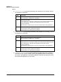
2. On Destination Node (Server)
On receiving the ‘read attributes’ request, the ZCL software on the destination node
performs the following steps:
1. Generates an E_ZCL_CBET_READ_REQUEST event for the destination
endpoint callback function which, if required, can update the shared device
structure that contains the attributes to be read, before the read takes place.
2. Generates an E_ZCL_CBET_LOCK_MUTEX event for the endpoint callback
function, which should lock the mutex that protects the shared device
structure - for information on mutexes, refer to the ZCL User Guide
(JN-UG-3077)
3. Reads the relevant attribute values from the shared device structure and
creates a ‘read attributes’ response message containing the read values.
4. Generates an E_ZCL_CBET_UNLOCK_MUTEX event for the endpoint
callback function, which should now unlock the mutex that protects the shared
device structure (other application tasks can now access the structure).
5. Sends the ‘read attributes’ response to the source node of the request.
JN-UG-3076 v1.0
© NXP Laboratories UK 2013
53
Chapter 4
HA Application Coding
3. On Source Node (Client)
On receiving the ‘read attributes’ response, the ZCL software on the source node
performs the following steps:
1. Generates an E_ZCL_CBET_LOCK_MUTEX event for the source endpoint
callback function, which should lock the mutex that protects the relevant
shared device structure on the source node.
2. Writes the new attribute values to the shared device structure on the source
node.
3. Generates an E_ZCL_CBET_UNLOCK_MUTEX event for the endpoint
callback function, which should now unlock the mutex that protects the shared
device structure (other application tasks can now access the structure).
4. For each attribute listed in the ‘read attributes’ response, it generates an
E_ZCL_CBET_READ_INDIVIDUAL_ATTRIBUTE_RESPONSE message for
the source endpoint callback function, which may or may not take action on
this message.
5. On completion of the parsing of the ‘read attributes’ response, it generates a
single E_ZCL_CBET_READ_ATTRIBUTES_RESPONSE message for the
source endpoint callback function, which may or may not take action on this
message.
Source Node
Endpoint
Destination Node
ZCL
ZCL
Endpoint
'Read Attributes' Message
'Read Attributes' Request
READ_REQUEST
LOCK_MUTEX
Read Attribute Values
Shared
Structure
UNLOCK_MUTEX
LOCK_MUTEX
Local
Shared
Structure
'Read Attributes' Response
Write Attribute Values
UNLOCK_MUTEX
READ_INDIVIDUAL_
ATTRIBUTE_RESPONSE
READ_ATTRIBUTES
_RESPONSE
Figure 2: ‘Read Attributes’ Request and Response
54
© NXP Laboratories UK 2013
JN-UG-3076 v1.0
ZigBee Home Automation
User Guide
Note: The ‘read attributes’ requests and responses
arrive at their destinations as data messages. Such a
message triggers a stack event of the type
ZPS_EVENT_APS_DATA_INDICATION, which is
handled as described in Section 4.7.
4.6 Writing Attributes
The ability to write attribute values to a remote cluster is required by some HA devices.
Normally, a ‘write attributes’ request is sent from a client cluster to a server cluster,
where the relevant attributes in the shared device structure are updated. Note that
write access to cluster attributes must be explicitly enabled at compile-time as
described in Section 3.5.1.
Three ‘write attributes’ functions are provided in the ZCL:
eZCL_SendWriteAttributesRequest(): This function sends a ‘write attributes’
request to a remote device, which attempts to update the attributes in its shared
structure. The remote device generates a ‘write attributes’ response to the
source device, indicating success or listing error codes for any attributes that it
could not update.
eZCL_SendWriteAttributesNoResponseRequest(): This function sends a
‘write attributes’ request to a remote device, which attempts to update the
attributes in its shared structure. However, the remote device does not
generate a ‘write attributes’ response, regardless of whether there are errors.
eZCL_SendWriteAttributesUndividedRequest(): This function sends a ‘write
attributes’ request to a remote device, which checks that all the attributes can
be written to without error:
If all attributes can be written without error, all the attributes are updated.
If any attribute is in error, all the attributes are left at their existing values.
The remote device generates a ‘write attributes’ response to the source device,
indicating success or listing error codes for attributes that are in error.
The activities surrounding a ‘write attributes’ request on the source and destination
nodes are outlined below and illustrated in Figure 3. Note that instances of the shared
device structure (which contains the relevant attributes) must be maintained on both
the source and destination nodes. The events generated from a ‘write attributes’
request are further described in Section 4.7.
JN-UG-3076 v1.0
© NXP Laboratories UK 2013
55
Chapter 4
HA Application Coding
1. On Source Node (Client)
In order to send a ‘write attributes’ request, the application on the source node
performs the following steps:
1. Locks the mutex that protects the local instance of the shared device structure
that contains the attributes to be updated - for information on mutexes, refer to
the ZCL User Guide (JN-UG-3077).
2. Writes one or more updated attribute values to the local instance of the shared
device structure.
3. Unlocks the mutex that protects the local instance of the shared device
structure.
4. Calls one of the above ZCL ‘write attributes’ functions to submit a request to
update the relevant attributes on a cluster on a remote node. The information
required by this function includes the following:
Source endpoint (from which the write request is to be sent)
Address of destination node for request
Destination endpoint (on destination node)
Identifier of the cluster containing the attributes [enumerations provided]
Number of attributes to be written
Array of identifiers of attributes to be written [enumerations provided]
From the above information, the function is able to pick up the relevant attribute
values from the local instance of the shared structure and incorporate them in
the message for the remote node.
2. On Destination Node (Server)
On receiving the ‘write attributes’ request, the ZCL software on the destination node
performs the following steps:
1. For each attribute in the ‘write attributes’ request, generates an
E_ZCL_CBET_CHECK_ATTRIBUTE_RANGE event for the destination
endpoint callback function. If required, the callback function can do either or
both of the following:
check that the new attribute value is in the correct range - if the value is
out-of-range, the function should set the eAttributeStatus field of the
event to E_ZCL_ERR_ATTRIBUTE RANGE
block the write by setting the eAttributeStatus field of the event to
E_ZCL_DENY_ATTRIBUTE_ACCESS
In the case of an out-of-range value or a blocked write, there is no further
processing for that particular attribute following the ‘write attributes’ request.
2. Generates an E_ZCL_CBET_LOCK_MUTEX event for the endpoint callback
function, which should lock the mutex that protects the relevant shared device
structure - for more on mutexes, refer to the ZCL User Guide (JN-UG-3077).
56
© NXP Laboratories UK 2013
JN-UG-3076 v1.0
ZigBee Home Automation
User Guide
3. Writes the relevant attribute values to the shared device structure - an
E_ZCL_CBET_WRITE_INDIVIDUAL_ATTRIBUTE event is generated for
each individual attempt to write an attribute value, which the endpoint callback
function can use to keep track of the successful and unsuccessful writes.
Note that if an ‘undivided write attributes’ request was received, an individual
failed write will render the whole update process unsuccessful.
4. Generates an E_ZCL_CBET_WRITE_ATTRIBUTES event to indicate that all
relevant attributes have been processed and, if required, creates a ‘write
attributes’ response message for the source node.
5. Generates an E_ZCL_CBET_UNLOCK_MUTEX event for the endpoint
callback function, which should now unlock the mutex that protects the shared
device structure (other application tasks can now access the structure).
6. If required, sends a ‘write attributes’ response to the source node of the
request.
3. On Source Node (Client)
On receiving an optional ‘write attributes’ response, the ZCL software on the source
node performs the following steps:
1. For each attribute listed in the ‘write attributes’ response, it generates an
E_ZCL_CBET_WRITE_INDIVIDUAL_ATTRIBUTE_RESPONSE message for
the source endpoint callback function, which may or may not take action on
this message. Only attributes for which the write has failed are included in the
response and will therefore result in one of these events.
2. On completion of the parsing of the ‘write attributes’ response, it generates a
single E_ZCL_CBET_WRITE_ATTRIBUTES_RESPONSE message for the
source endpoint callback function, which may or may not take action on this
message.
JN-UG-3076 v1.0
© NXP Laboratories UK 2013
57
Chapter 4
HA Application Coding
Source Node
Endpoint
Destination Node
ZCL
ZCL
Endpoint
Lock mutex for
local shared structure
Local
Shared
Structure
Write attribute values
Unlock mutex for
local shared structure
'Write Attributes' Message
'Write Attributes' Request
CHECK_ATTRIBUTE_RANGE
LOCK_MUTEX
Write Attribute Value
Shared
Structure
WRITE_INDIVIDUAL_ATTRIBUTE
WRITE_ATTRIBUTES
UNLOCK_MUTEX
'Write Attributes' Response
WRITE_INDIVIDUAL_
ATTRIBUTE_RESPONSE
WRITE_ATTRIBUTES
_RESPONSE
Figure 3: ‘Write Attributes’ Request and Response
Note: The ‘write attributes’ requests and responses
arrive at their destinations as data messages. Such a
message triggers a stack event of the type
ZPS_EVENT_APS_DATA_INDICATION, which is
handled as described in Section 4.7.
58
© NXP Laboratories UK 2013
JN-UG-3076 v1.0
ZigBee Home Automation
User Guide
4.7 Handling Stack and Timer Events
This section outlines the event handling framework which allows an HA application to
deal with stack-related and timer-related events. A stack event is triggered by a
message arriving in a message queue and a timer event is triggered when a JenOS
timer expires.
The event handling framework for HA is provided by the ZCL. The event must be
wrapped in a tsZCL_CallBackEvent structure by the application, which then
passes this event structure into the ZCL using the function vZCL_EventHandler().
The ZCL processes the event and, if necessary, invokes the relevant endpoint
callback function. This event structure and event handler function are detailed in the
ZCL User Guide (JN-UG-3077), which also provides more details of event processing.
The events that are not cluster-specific are divided into four categories, as shown in
Table 19 below - these events are described in the ZCL User Guide (JN-UG-3077).
Cluster-specific events are covered in the chapter for the relevant cluster.
Category
Event
Input Events
E_ZCL_ZIGBEE_EVENT
E_ZCL_CBET_TIMER
Read Events
E_ZCL_CBET_READ_REQUEST
E_ZCL_CBET_READ_INDIVIDUAL_ATTRIBUTE_RESPONSE
E_ZCL_CBET_READ_ATTRIBUTES_RESPONSE
Write Events
E_ZCL_CBET_CHECK_ATTRIBUTE_RANGE
E_ZCL_CBET_WRITE_INDIVIDUAL_ATTRIBUTE
E_ZCL_CBET_WRITE_ATTRIBUTES
E_ZCL_CBET_WRITE_INDIVIDUAL_ATTRIBUTE_RESPONSE
E_ZCL_CBET_WRITE_ATTRIBUTES_RESPONSE
General Events
E_ZCL_CBET_LOCK_MUTEX
E_ZCL_CBET_UNLOCK_MUTEX
E_ZCL_CBET_DEFAULT_RESPONSE
E_ZCL_CBET_UNHANDLED_EVENT
E_ZCL_CBET_ERROR
Table 19: Events (Not Cluster-Specific)
Note: ZCL error events and default responses may be
generated when problems occur in receiving
commands. The possible ZCL status codes contained in
the events and responses are detailed in the ZCL User
Guide (JN-UG-3077).
JN-UG-3076 v1.0
© NXP Laboratories UK 2013
59
Chapter 4
HA Application Coding
4.8 Servicing Timing Requirements
Some clusters used by an HA application may have timing requirements which
demand periodic updates. The function eHA_Update100mS() is provided to service
these requirements and should be called repeatedly every 100 ms. Invocation of this
function can be prompted using a 100-ms software timer.
The function eHA_Update100mS() calls the external function vIdEffectTick(), which
must be defined in the application. This user-defined function can be used to
implement an identify effect on the node, if required. Otherwise, it should be defined
but left empty.
4.9 Time Management
A Home Automation device may need to keep track of time for its own purposes. It is
not usually necessary to synchronise time between the nodes of an HA network and
therefore an HA device does not normally require the Time cluster. An HA device uses
‘ZCL time’, which is a time in seconds maintained locally by the device.
In the NXP implementation of the ZigBee Cluster Library, ZCL time on a device is
normally derived from a software timer provided by JenOS. In addition, HA requires a
100-ms timer to periodically notify the device when 100 milliseconds have passed.
Typically, both of these timings are derived from the same JenOS timer. The
maintenance of ZCL time and the 100-ms timing is described in the sub-sections
below.
Note: The functions vZCL_SetUTCTime() and
vZCL_EventHandler(), referenced below, are
described in the ZCL User Guide (JN-UG-3077) and the
function OS_eContinueSWTimer() is described in the
JenOS User Guide (JN-UG-3075).
60
© NXP Laboratories UK 2013
JN-UG-3076 v1.0
ZigBee Home Automation
User Guide
4.9.1 Time Maintenance
ZCL time should be incremented once per second. In addition, an HA device must be
prompted every 100 milliseconds to perform certain periodic operations (e.g. level
transitions performed by the Level Control cluster). Normally, the same 100-ms
JenOS timer is used for both timings, as follows:
1. On expiration of the 100-ms JenOS timer, an event is generated (from the
hardware/software timer that drives the JenOS timer) which causes JenOS to
activate an application task.
2. Within this task, the application must call eHA_Update100mS() on each
activation of the task - this function is described in Chapter 11.
3. Every ten times that the task is activated, the application must also call
vZCL_EventHandler() with an event type of E_ZCL_CBET_TIMER.
This results in the timer event being passed to the ZCL once per second. On
receiving each timer event, the ZCL automatically increments the ZCL time and
may run cluster-specific schedulers.
4. The user task must finally resume the 100-ms timer using the JenOS function
OS_eContinueSWTimer().
Note 1: The function eHA_Update100mS() calls the
external function vIdEffectTick(), which must be
defined in the application. This user-defined function
can be used to implement an identify effect on the node,
if required. Otherwise, it should be defined but left
empty.
Note 2: For more information on using the function
vZCL_EventHandler() to pass a timer event to the ZCL,
refer to the ‘Processing Events’ section of the ZCL User
Guide (JN-UG-3077).
JN-UG-3076 v1.0
© NXP Laboratories UK 2013
61
Chapter 4
HA Application Coding
4.9.2 Updating ZCL Time Following Sleep
An HA network may include nodes that conserve energy by sleeping between
activities. For example:
A switch device will normally be a sleeping End Device which wakes on an
interrupt generated by the switch or dimmer hardware. If a switch supports the
Identify cluster, while in identification mode it must wake once per second to
generate a timer event - refer to the section on the Identify cluster in the ZCL
User Guide (JN-UG-3077).
A light device is normally configured as a Router, in which case it is always
active and therefore does not sleep. If a light device does sleep, it must wake at
least once every 100 ms to call eHA_Update100mS() and also to generate a
timer event once every second (see Section 4.9.1).
In the case of a device that sleeps, on waking from sleep the application should update
the ZCL time using the function vZCL_SetUTCTime() according to the duration for
which the device was asleep. This requires the sleep duration to be timed.
While sleeping, the JN5168 microcontroller normally uses its RC oscillator for timing
purposes, which may not maintain the required accuracy for certain applications. In
such cases, a more accurate external crystal should be used to time the sleep periods.
The vZCL_SetUTCTime() function does not cause timer events to be executed. If the
device is awake for less than one second, the application should generate a
E_ZCL_CBET_TIMER event to prompt the ZCL to run any timer-related functions.
Note that when passed into vZCL_EventHandler(), this event will increment the ZCL
time by one second.
62
© NXP Laboratories UK 2013
JN-UG-3076 v1.0
ZigBee Home Automation
User Guide
Part II:
HA Clusters and Modules
JN-UG-3076 v1.0
© NXP Laboratories UK 2013
63
64
© NXP Laboratories UK 2013
JN-UG-3076 v1.0
ZigBee Home Automation
User Guide
5. ZCL Clusters
The HA application profile uses certain clusters that are provided in the ZigBee Cluster
Library (ZCL):
Basic - see Section 5.1
Identify - see Section 5.2
Groups - see Section 5.3
Scenes - see Section 5.4
On/Off - see Section 5.5
On/Off Switch Configuration - see Section 5.6
Level Control - see Section 5.7
Door Lock - see Section 5.8
Binary Input (Basic) - see Section 5.9
Colour Control - see Section 5.10
Illuminance Measurement - see Section 5.11
Occupancy Sensing - see Section 5.12
The above clusters are introduced below but are fully detailed in the ZCL User Guide
(JN-UG-3077).
5.1 Basic Cluster
The Basic cluster holds basic information about a device/endpoint.
The Basic cluster has a Cluster ID of 0x0000.
It is a mandatory server-side (input) cluster for all ZigBee HA devices except the
Simple Sensor.
JN-UG-3076 v1.0
© NXP Laboratories UK 2013
65
Chapter 5
ZCL Clusters
5.2 Identify Cluster
The Identify cluster allows a device to identify itself (for example, by flashing a LED on
the node).
The Identify cluster has a Cluster ID of 0x0003.
It is required in HA devices as indicated in the table below.
Mandatory in...
Server-side
Client-side
All HA devices except
Simple Sensor
Door Lock Controller
Optional in...
On/Off Switch
Level Control Switch
Scene Selector
Remote Control
On/Off Light Switch
Colour Dimmer Switch
Table 20: Identify Cluster in HA Devices
5.3 Groups Cluster
The Groups cluster allows the management of the Group table concerned with group
addressing.
The Groups cluster has a Cluster ID of 0x0004.
It is required in HA devices as indicated in the table below.
Mandatory in...
Optional in...
Server-side
Client-side
On/Off Output
Door Lock
Simple Sensor
On/Off Light
Dimmable Light
Colour Dimmable Light
Scene Selector
Door Lock Controller
On/Off Switch
Level Control Switch
Remote Control
On/Off Light Switch
Dimmer Switch
Colour Dimmer Switch
Light Sensor
Occupancy Sensor
Table 21: Groups Cluster in HA Devices
66
© NXP Laboratories UK 2013
JN-UG-3076 v1.0
ZigBee Home Automation
User Guide
5.4 Scenes Cluster
The Scenes cluster allows values that make up a ‘scene’ to be set and retrieved.
The Scenes cluster has a Cluster ID of 0x0005.
It is required in HA devices as indicated in the table below.
Mandatory in...
Server-side
Client-side
On/Off Output
Door Lock
Simple Sensor
On/Off Light
Dimmable Light
Colour Dimmable Light
Scene Selector
Door Lock Controller
Optional in...
On/Off Switch
Level Control Switch
Remote Control
On/Off Light Switch
Dimmer Switch
Colour Dimmer Switch
Table 22: Scenes Cluster in HA Devices
5.5 On/Off Cluster
The On/Off cluster allows a device to be put into the ‘on’ and ‘off’ states, or toggled
between the two states.
The On/Off cluster has a Cluster ID of 0x0006.
It is required in HA devices as indicated in the table below.
Mandatory in...
Optional in...
Server-side
Client-side
On/Off Output
On/Off Light
Dimmable Light
Colour Dimmable Light
On/Off Switch
Level Control Switch
On/Off Light Switch
Dimmer Switch
Colour Dimmer Switch
Remote Control
Table 23: On/Off Cluster in HA Devices
JN-UG-3076 v1.0
© NXP Laboratories UK 2013
67
Chapter 5
ZCL Clusters
5.6 On/Off Switch Configuration Cluster
The On/Off Switch Configuration cluster allows the switch type on a device to be
defined, as well as the commands to be generated when the switch is moved between
its two states.
The On/Off cluster has a Cluster ID of 0x0007.
It is required in HA devices as indicated in the table below.
Server-side
Client-side
On/Off Switch
Level Control Switch
On/Off Light Switch
Dimmer Switch
Colour Dimmer Switch
Remote Control
Mandatory in...
Optional in...
Table 24: On/Off Switch Configuration Cluster in HA Devices
5.7 Level Control Cluster
The Level Control cluster is used to control the level of a physical quantity on a device
(e.g. heat output).
The Level Control cluster has a Cluster ID of 0x0008.
It is required in HA devices as indicated in the table below.
Mandatory in...
Optional in...
Server-side
Client-side
Dimmable Light
Colour Dimmable Light
Level Control Switch
Dimmer Switch
Colour Dimmer Switch
Remote Control
Table 25: Level Control Cluster in HA Devices
68
© NXP Laboratories UK 2013
JN-UG-3076 v1.0
ZigBee Home Automation
User Guide
5.8 Door Lock Cluster
The Door Lock cluster provides an interface to a set values representing the state of
a door lock and (optionally) the door.
The Door Lock cluster has a Cluster ID of 0x000A.
Its required in HA devices as indicated in the table below.
Mandatory in...
Server-side
Client-side
Door Lock
Door Lock Controller
Optional in...
Remote Control
Table 26: Door Lock Cluster in HA Devices
In Home Automation, the Door Lock cluster is enhanced with an extra optional
attribute which allows Application-level security to be used (in addition to the default
Network-level security). This enhancement is described in the ZCL User Guide
(JN-UG-3077).
5.9 Binary Input (Basic) Cluster
The Binary Input (Basic) cluster is used to read the value of a binary measurement
representing the state of a two-state physical quantity.
The Binary Input (Basic) cluster has a Cluster ID of 0x000F.
It is required in HA devices as indicated in the table below.
Server-side
Mandatory in...
Client-side
Simple Sensor
Optional in...
Table 27: Binary Input (Basic) Cluster in HA Devices
JN-UG-3076 v1.0
© NXP Laboratories UK 2013
69
Chapter 5
ZCL Clusters
5.10 Colour Control Cluster
The Colour Control cluster is used to control the colour of a light.
The Colour Control cluster has a Cluster ID of 0x0300.
It is required in HA devices as indicated in the table below. However, note that the
Colour Control cluster is not certifiable for Home Automation 1.1.
Mandatory in...
Server-side
Client-side
Colour Dimmable Light
Colour Dimmer Switch
Optional in...
Remote Control
Table 28: Colour Control Cluster in HA Devices
To use the Colour Control cluster with the HA profile, the following definitions must be
added to the zcl_options.h file to enable the corresponding optional attributes:
#define CLD_COLOURCONTROL_ATTR_NUMBER_OF_PRIMARIES 6
#define CLD_COLOURCONTROL_ATTR_CURRENT_SATURATION
#define CLD_COLOURCONTROL_ATTR_CURRENT_HUE
#define CLD_COLOURCONTROL_ATTR_COLOUR_TEMPERATURE
#define CLD_COLOURCONTROL_ATTR_COLOUR_LOOP_ACTIVE
#define CLD_COLOURCONTROL_ATTR_COLOUR_LOOP_STORED_ENHANCED_HUE
#define CLD_COLOURCONTROL_ATTR_ENHANCED_CURRENT_HUE
Any further dependent attributes must also be set up appropriately. For example,
when defining “CLD_COLOURCONTROL_ATTR_NUMBER_OF_PRIMARIES 6”,
definitions will also be required for CLD_COLOURCONTROL_PRIMARY_1_X,
CLD_COLOURCONTROL_PRIMARY_1_Y and so on (for 6 primary colours),
otherwise the number of primaries will default to 0.
When the Colour Control cluster is used with the Scenes cluster in the HA profile, only
the mandatory Colour Control cluster attributes u16CurrentX and u16CurrentY
can be stored in and recalled from scenes. To enable this scenes functionality, the
following definition must be added to the zcl_options.h file:
#define HA_RECALL_SCENES
70
© NXP Laboratories UK 2013
JN-UG-3076 v1.0
ZigBee Home Automation
User Guide
5.11 Illuminance Measurement Cluster
The Illuminance Measurement cluster is used to interface with a set of values related
to an illuminance measurement.
The Illuminance Measurement cluster has a Cluster ID of 0x0400.
It is required in HA devices as indicated in the table below.
Server-side
Mandatory in...
Client-side
Light Sensor
Optional in...
Remote Control
Table 29: Illuminance Measurement Cluster in HA Devices
5.12 Occupancy Sensing Cluster
The Occupancy Sensing cluster is used to interface with a set of values related to
occupancy sensing.
The Occupancy Sensing cluster has a Cluster ID of 0x0406.
It is required in HA devices as indicated in the table below.
Server-side
Mandatory in...
Optional in...
Client-side
Occupancy Sensor
On/Off Light
Dimmable Light
Colour Dimmable Light
Table 30: Occupancy Sensing Cluster in HA Devices
JN-UG-3076 v1.0
© NXP Laboratories UK 2013
71
Chapter 5
ZCL Clusters
72
© NXP Laboratories UK 2013
JN-UG-3076 v1.0
ZigBee Home Automation
User Guide
6. Appliance Control Cluster
This chapter outlines the Appliance Control cluster which is defined in the ZigBee
Home Automation profile, and provides an interface for remotely controlling
appliances in the home.
The Appliance Control cluster has a Cluster ID of 0x001B.
6.1 Overview
The Appliance Control cluster provides an interface for the remote control and
programming of home appliances (e.g. a washing machine) by sending basic
operational commands such as start, pause, stop.
The cluster is enabled by defining CLD_APPLIANCE_CONTROL in the
zcl_options.h file - see Section 3.5.1. Further compile-time options for the Appliance
Control cluster are detailed in Section 6.9.
All attributes of the Appliance Control cluster are in the ‘Appliance Functions’ attribute
set.
6.2 Cluster Structure and Attributes
The Appliance Control cluster is contained in the following
tsCLD_ApplianceControl structure:
typedef struct
{
zuint16 u16StartTime;
zuint16 u16FinishTime;
#ifdef CLD_APPLIANCE_CONTROL_REMAINING_TIME
zuint16 u16RemainingTime;
#endif
} tsCLD_ApplianceControl;
JN-UG-3076 v1.0
© NXP Laboratories UK 2013
73
Chapter 6
Appliance Control Cluster
where:
u16StartTime is a bitmap representing the start-time of a ‘running’ cycle of
the appliance, as follows:
Bits
Description
0-5
Minutes part of the start-time, in the range 0 to 59
(may be absolute or relative time - see below)
6-7
Type of time encoding:
• 0x0: Relative time - start-time is a delay from the time that the attribute was set
• 0x1: Absolute time - start-time is an actual time of the 24-hour clock
• 0x2-0x3: Reserved
The defaults are absolute time for ovens and relative time for other appliances.
8-15
Hours part of the start-time:
• in the range 0 to 255, if relative time selected
• in the range 0 to 23, if absolute time selected
u16FinishTime is a bitmap representing the stop-time of a ‘running’ cycle of
the appliance, as follows:
Bits
Description
0-5
Minutes part of the stop-time, in the range 0 to 59
(may be absolute or relative time - see below)
6-7
Type of time encoding:
• 0x0: Relative time - stop-time is a delay from the time that the attribute was set
• 0x1: Absolute time - stop-time is an actual time of the 24-hour clock
• 0x2-0x3: Reserved
The defaults are absolute time for ovens and relative time for other appliances.
8-15
Hours part of the stop-time:
• in the range 0 to 255, if relative time selected
• in the range 0 to 23, if absolute time selected
u16RemainingTime is an optional attribute indicating the time, in minutes,
remaining in the current ‘running’ cycle of the appliance (time until the end of
the cycle) - this attribute is constantly updated during the running cycle and is
zero when the appliance is not running
74
© NXP Laboratories UK 2013
JN-UG-3076 v1.0
ZigBee Home Automation
User Guide
6.3 Sending Commands
The Appliance Control cluster server resides on the appliance to be controlled (e.g. a
washing machine) and the cluster client resides on the controlling device (normally a
remote control unit).
The commands from the client to the server can be of two types:
‘Execution’ commands, requesting appliance operations
‘Status’ commands, requesting appliance status information
In addition, status notification messages can be sent unsolicited from the server to the
client.
Sending the above messages is described in the sub-sections below.
6.3.1 Execution Commands from Client to Server
An ‘execution’ command can be sent from the client to request that an operation is
performed on the appliance (server) - the request is sent in an ‘Execution of
Command’ message. The application on the client can send this message by calling
the function eCLD_ACExecutionOfCommandSend().
The possible operations depend on the target appliance but the following operations
are available to be specified in the payload of the message (described in Section
6.8.2):
Start appliance cycle
Stop appliance cycle
Pause appliance cycle
Start superfreezing cycle
Stop superfreezing cycle
Start supercooling cycle
Stop supercooling cycle
Disable gas
Enable gas
In the start and stop commands, the start-time and end-time can be specified. The
commands are fully detailed in the British Standards document BS EN 50523.
The application on the server (appliance) will be notified of the received command by
an E_CLD_APPLIANCE_CONTROL_CMD_EXECUTION_OF_COMMAND event
(Appliance Control events are described in Section 6.4). The required command is
specified in the payload of the message, which is contained in the above event. The
application must then perform the requested command (if possible).
JN-UG-3076 v1.0
© NXP Laboratories UK 2013
75
Chapter 6
Appliance Control Cluster
6.3.2 Status Commands from Client to Server
The application on the cluster client can request the current status of the appliance by
sending a ‘Signal State’ message to the cluster server on the appliance. This message
can be sent by calling the function eCLD_ACSignalStateSend(). This function returns
immediately and the requested status information is later returned in an
E_CLD_APPLIANCE_CONTROL_CMD_SIGNAL_STATE_RESPONSE event,
which is generated when a response arrives from the server (Appliance Control events
are described in Section 6.4).
Note: The cluster server handles the ‘Signal State’
message automatically and returns the requested status
information in a ‘Signal State Response’ message to the
client.
The appliance status information from the message payload is contained in the above
event - for details of this payload and the status information, refer to Section 6.8.3.
6.3.3 Status Notifications from Server to Client
The cluster server on the appliance can send unsolicited status notifications to the
client in ‘Signal State Notification’ messages. A message of this kind can be sent by
the application on the server by calling either of the following functions:
eCLD_ACSignalStateNotificationSend()
eCLD_ACSignalStateResponseORSignalStateNotificationSend()
Note: The latter function is also used internally by the
cluster server to send a ‘Signal State Response’
message - see Section 6.3.2.
The appliance status information from the ‘Signal State Notification’ message is
reported to the application on the cluster client through the event
E_CLD_APPLIANCE_CONTROL_CMD_SIGNAL_STATE_NOTIFICATION, which is
generated when the notification arrives from the server (Appliance Control events are
described in Section 6.4). The appliance status information from the message payload
is contained in the above event - for details of this payload and the status information,
refer to Section 6.8.3.
76
© NXP Laboratories UK 2013
JN-UG-3076 v1.0
ZigBee Home Automation
User Guide
6.4 Appliance Control Events
The Appliance Control cluster has its own events that are handled through the
callback mechanism outlined in Section 4.7 (and fully detailed in the ZCL User Guide
(JN-UG-3077)). If a device uses the Appliance Control cluster then Appliance Control
event handling must be included in the callback function for the associated endpoint,
where this callback function is registered through the relevant endpoint registration
function. The relevant callback function will then be invoked when an Appliance
Control event occurs.
For an Appliance Control event, the eEventType field of the
tsZCL_CallBackEvent structure is set to E_ZCL_CBET_CLUSTER_CUSTOM.
This event structure also contains an element sClusterCustomMessage, which is
itself a structure containing a field pvCustomData. This field is a pointer to the
following tsCLD_ApplianceControlCallBackMessage structure:
typedef struct
{
uint8
bool
u8CommandId;
*pbApplianceStatusTwoPresent;
union
{
tsCLD_AC_ExecutionOfCommandPayload *psExecutionOfCommandPayload;
tsCLD_AC_SignalStateResponseORSignalStateNotificationPayload
*psSignalStateResponseAndNotificationPayload;
} uMessage;
} tsCLD_ApplianceControlCallBackMessage;
When an Appliance Control event occurs, one of four command types could have
been received. The relevant command type is specified through the u8CommandId
field of the tsSM_CallBackMessage structure. The possible command types are
detailed the tables below for events generated on a server and a client.
u8CommandId Enumeration
Description
E_CLD_APPLIANCE_CONTROL_
CMD_EXECUTION_OF_COMMAND
An ‘Execution of Command’ message has been
received by the server (appliance), requesting an operation on the appliance
E_CLD_APPLIANCE_CONTROL_
CMD_SIGNAL_STATE
A ‘Signal State’ message has been received by the
server (appliance), requesting the status of the appliance
Table 31: Appliance Control Command Types (Events on Server)
JN-UG-3076 v1.0
© NXP Laboratories UK 2013
77
Chapter 6
Appliance Control Cluster
u8CommandId Enumeration
Description
E_CLD_APPLIANCE_CONTROL_CMD
_SIGNAL_STATE_RESPONSE
A response to a ‘Signal State’ message has been
received by the client, containing the requested appliance status
E_CLD_APPLIANCE_CONTROL_CMD
_SIGNAL_STATE_NOTIFICATION
A ‘Signal State’ notification message has been received
by the client, containing unsolicited status information
Table 32: Appliance Control Command Types (Events on Client)
6.5 Functions
The following Appliance Control cluster functions are provided in the HA API:
Function
Page
eCLD_ApplianceControlCreateApplianceControl
79
eCLD_ACExecutionOfCommandSend
81
eCLD_ACSignalStateSend
83
eCLD_ACSignalStateResponseORSignalStateNotificationSend
84
eCLD_ACSignalStateNotificationSend
86
eCLD_ACChangeAttributeTime
88
78
© NXP Laboratories UK 2013
JN-UG-3076 v1.0
ZigBee Home Automation
User Guide
eCLD_ApplianceControlCreateApplianceControl
teZCL_Status
eCLD_ApplianceControlCreateApplianceControl(
tsZCL_ClusterInstance *psClusterInstance,
bool_t bIsServer,
tsZCL_ClusterDefinition *psClusterDefinition,
void *pvEndPointSharedStructPtr,
uint8 *pu8AttributeControlBits,
tsCLD_ApplianceControlCustomDataStructure
*psCustomDataStructure);
Description
This function creates an instance of the Appliance Control cluster on an endpoint.
The cluster instance is created on the endpoint which is associated with the supplied
tsZCL_ClusterInstance structure and can act as a server or a client, as
specified.
The function should only be called when setting up a custom endpoint containing one
or more selected clusters (rather than the whole set of clusters supported by a
standard ZigBee device). This function will create an Appliance Control cluster
instance on the endpoint, but instances of other clusters may also be created on the
same endpoint by calling their corresponding creation functions. For more details of
creating cluster instances on custom endpoints, refer to Appendix A.
Note: This function must not be called for an endpoint on
which a standard ZigBee device will be used. In this case, the
device and its supported clusters must be registered on the
endpoint using the relevant device registration function from
those described in Chapter 11.
When used, this function must be the first Appliance Control cluster function called
in the application, and must be called after the stack has been started and after the
application profile has been initialised.
The function requires an array to be declared for internal use, which contains one
element (of type uint8) for each attribute of the cluster. The array length should
therefore equate to the total number of attributes supported by the Appliance Control
cluster, which can be obtained by using the macro
CLD_APPLIANCE_CONTROL_MAX_NUMBER_OF_ATTRIBUTE.
The array declaration should be as follows:
uint8 au8AppApplianceControlClusterAttributeControlBits[
CLD_APPLIANCE_CONTROL_MAX_NUMBER_OF_ATTRIBUTE];
The function will initialise the array elements to zero.
JN-UG-3076 v1.0
© NXP Laboratories UK 2013
79
Chapter 6
Appliance Control Cluster
Parameters
psClusterInstance
Pointer to structure containing information about the
cluster instance to be created (see the ZCL User Guide
(JN-UG-3077)). This structure will be updated by the
function by initialising individual structure fields.
bIsServer
Type of cluster instance (server or client) to be created:
TRUE - server
FALSE - client
psClusterDefinition
Pointer to structure indicating the type of cluster to be
created (see the ZCL User Guide (JN-UG-3077)). In
this case, this structure must contain the details of the
Appliance Control cluster. This parameter can refer to a
pre-filled structure called sCLD_ApplianceControl
which is provided in the ApplianceControl.h file.
pvEndPointSharedStructPtr Pointer to the shared structure used for attribute
storage. This parameter should be the address of the
structure of type tsCLD_ApplianceControl which
defines the attributes of Appliance Control cluster. The
function will initialise the attributes with default values.
pu8AttributeControlBits
Pointer to an array of uint8 values, with one element for
each attribute in the cluster (see above).
psCustomDataStructure
Pointer to a structure containing the storage for internal
functions of the cluster (see Section 6.8.4)
Returns
E_ZCL_SUCCESS
E_ZCL_FAIL
E_ZCL_ERR_PARAMETER_NULL
E_ZCL_ERR_INVALID_VALUE
80
© NXP Laboratories UK 2013
JN-UG-3076 v1.0
ZigBee Home Automation
User Guide
eCLD_ACExecutionOfCommandSend
teZCL_Status eCLD_ACExecutionOfCommandSend(
uint8 u8SourceEndPointId,
uint8 u8DestinationEndPointId,
tsZCL_Address *psDestinationAddress,
uint8 *pu8TransactionSequenceNumber,
tsCLD_AC_ExecutionOfCommandPayload *psPayload);
Description
This function can be used on an Appliance Control cluster client to send an
‘Execution of Command’ message to a cluster server (appliance), where this
message may specify one of the following control commands:
Start appliance cycle
Stop appliance cycle
Pause appliance cycle
Start superfreezing cycle
Stop superfreezing cycle
Start supercooling cycle
Stop supercooling cycle
Disable gas
Enable gas
The required command is specified in the payload of the message (a pointer to this
payload must be provided). The commands are fully detailed in the British Standards
document BS EN 50523.
You are required to provide a pointer to a location to receive a Transaction Sequence
Number (TSN) for the message. The TSN in the response will be set to match the
TSN in the request, allowing an incoming response to be paired with a request. This
is useful when sending more than one request to the same destination endpoint.
Parameter
JN-UG-3076 v1.0
u8SourceEndPointId
Number of the local endpoint through which to
send the message. This parameter is used
both to send the message and to identify the
instance of the shared structure holding the
required attribute values
u8DestinationEndPointId
Number of the endpoint on the remote node to
which the message will be sent. This
parameter is ignored when sending to
address types eZCL_AMBOUND and
eZCL_AMGROUP
psDestinationAddress
Pointer to a structure holding the address of
the node to which the request will be sent
© NXP Laboratories UK 2013
81
Chapter 6
Appliance Control Cluster
pu8TransactionSequenceNumber
Pointer to a location to receive the
Transaction Sequence Number (TSN) of the
message
psPayload
Pointer to a structure containing the payload
for the message (see Section 6.8.2).
Returns
E_ZCL_SUCCESS
E_ZCL_FAIL
E_ZCL_ERR_PARAMETER_NULL
E_ZCL_ERR_INVALID_VALUE
82
© NXP Laboratories UK 2013
JN-UG-3076 v1.0
ZigBee Home Automation
User Guide
eCLD_ACSignalStateSend
teZCL_Status eCLD_ACSignalStateSend(
uint8 u8SourceEndPointId,
uint8 u8DestinationEndPointId,
tsZCL_Address *psDestinationAddress,
uint8 *pu8TransactionSequenceNumber);
Description
This function can be used on an Appliance Control cluster client to send a ‘Signal
State’ message to a cluster server (appliance), which requests the status of the
appliance. The function returns immediately and the requested status information is
later returned in the following event, which is generated when a response is received
from the server:
E_CLD_APPLIANCE_CONTROL_CMD_SIGNAL_STATE_RESPONSE
You are required to provide a pointer to a location to receive a Transaction Sequence
Number (TSN) for the message. The TSN in the response will be set to match the
TSN in the request, allowing an incoming response to be paired with a request. This
is useful when sending more than one request to the same destination endpoint.
Parameters
u8SourceEndPointId
Number of the local endpoint through which to
send the message. This parameter is used
both to send the message and to identify the
instance of the shared structure holding the
required attribute values
u8DestinationEndPointId
Number of the endpoint on the remote node to
which the message will be sent. This
parameter is ignored when sending to
address types eZCL_AMBOUND and
eZCL_AMGROUP
psDestinationAddress
Pointer to a structure holding the address of
the node to which the message will be sent
pu8TransactionSequenceNumber
Pointer to a location to receive the
Transaction Sequence Number (TSN) of the
message
Returns
E_ZCL_SUCCESS
E_ZCL_FAIL
E_ZCL_ERR_PARAMETER_NULL
E_ZCL_ERR_INVALID_VALUE
JN-UG-3076 v1.0
© NXP Laboratories UK 2013
83
Chapter 6
Appliance Control Cluster
eCLD_ACSignalStateResponseORSignalStateNotificationSend
teZCL_Status
eCLD_ACSignalStateResponseORSignalStateNotificationSend(
uint8 u8SourceEndPointId,
uint8 u8DestinationEndPointId,
tsZCL_Address *psDestinationAddress,
uint8 *pu8TransactionSequenceNumber,
teCLD_ApplianceControl_ServerCommandId eCommandId,
bool bApplianceStatusTwoPresent,
tsCLD_AC_SignalStateResponseORSignalStateNotificationPayload
*psPayload);
Description
This function can be used on an Appliance Control cluster server to send a ‘Signal
State Response’ message (in reply to a ‘Signal State Request’ message) or an
unsolicited ‘Signal State Notification’ message to a cluster client.
The command to be sent must be specified as one of:
E_CLD_APPLIANCE_CONTROL_CMD_SIGNAL_STATE_RESPONSE
E_CLD_APPLIANCE_CONTROL_CMD_SIGNAL_STATE_NOTIFICATION
You are required to provide a pointer to a location to receive a Transaction Sequence
Number (TSN) for the message. The TSN in the response will be set to match the
TSN in the request, allowing an incoming response to be paired with a request. This
is useful when sending more than one request to the same destination endpoint.
Parameters
84
u8SourceEndPointId
Number of the local endpoint through which to
send the message. This parameter is used
both to send the message and to identify the
instance of the shared structure holding the
required attribute values
u8DestinationEndPointId
Number of the endpoint on the remote node to
which the message will be sent. This
parameter is ignored when sending to
address types eZCL_AMBOUND and
eZCL_AMGROUP
psDestinationAddress
Pointer to a structure holding the address of
the node to which the message will be sent
pu8TransactionSequenceNumber
Pointer to a location to receive the
Transaction Sequence Number (TSN) of the
message
eCommandId
Enumeration indicating the command to be
sent (see above and Section 6.7.3)
© NXP Laboratories UK 2013
JN-UG-3076 v1.0
ZigBee Home Automation
User Guide
bApplianceStatusTwoPresent
Boolean indicating whether additional
appliance status data is present in payload:
TRUE - Present
FALSE - Not present
psPayload
Pointer to structure containing payload for
message (see above and Section 6.8.3)
Returns
E_ZCL_SUCCESS
E_ZCL_FAIL
E_ZCL_ERR_PARAMETER_NULL
E_ZCL_ERR_INVALID_VALUE
JN-UG-3076 v1.0
© NXP Laboratories UK 2013
85
Chapter 6
Appliance Control Cluster
eCLD_ACSignalStateNotificationSend
teZCL_Status eCLD_ACSignalStateNotificationSend(
uint8 u8SourceEndPointId,
uint8 u8DestinationEndPointId,
tsZCL_Address *psDestinationAddress,
uint8 *pu8TransactionSequenceNumber,
bool bApplianceStatusTwoPresent,
tsCLD_AC_SignalStateResponseORSignalStateNotificationPayload
*psPayload);
Description
This function can be used on an Appliance Control cluster server to send an
unsolicited ‘Signal State Notification’ message to a cluster client. The function is an
alternative to eCLD_ACSignalStateResponseORSignalStateNotificationSend().
You are required to provide a pointer to a location to receive a Transaction Sequence
Number (TSN) for the message. The TSN in the response will be set to match the
TSN in the request, allowing an incoming response to be paired with a request. This
is useful when sending more than one request to the same destination endpoint.
Parameters
u8SourceEndPointId
Number of the local endpoint through which to
send the message. This parameter is used
both to send the message and to identify the
instance of the shared structure holding the
required attribute values
u8DestinationEndPointId
Number of the endpoint on the remote node to
which the message will be sent. This
parameter is ignored when sending to
address types eZCL_AMBOUND and
eZCL_AMGROUP
psDestinationAddress
Pointer to a structure holding the address of
the node to which the message will be sent
pu8TransactionSequenceNumber
Pointer to a location to receive the
Transaction Sequence Number (TSN) of the
message
bApplianceStatusTwoPresent
Boolean indicating whether additional
appliance status data is present in payload:
TRUE - Present
FALSE - Not present
psPayload
86
Pointer to structure containing payload for
message (see above and Section 6.8.3)
© NXP Laboratories UK 2013
JN-UG-3076 v1.0
ZigBee Home Automation
User Guide
Returns
E_ZCL_SUCCESS
E_ZCL_FAIL
E_ZCL_ERR_PARAMETER_NULL
E_ZCL_ERR_INVALID_VALUE
JN-UG-3076 v1.0
© NXP Laboratories UK 2013
87
Chapter 6
Appliance Control Cluster
eCLD_ACChangeAttributeTime
teZCL_Status eCLD_ACChangeAttributeTime(
uint8 u8SourceEndPointId,
teCLD_ApplianceControl_Cluster_AttrID eAttributeTimeId,
uint16 u16TimeValue);
Description
This function can be used on an Appliance Control cluster server (appliance) to
update the time attributes of the cluster (start time, finish time, remaining time). This
is particularly useful if the host node has its own timer.
The target attribute must be specified using one of:
E_CLD_APPLIANCE_CONTROL_ATTR_ID_START_TIME
E_CLD_APPLIANCE_CONTROL_ATTR_ID_FINISH_TIME
E_CLD_APPLIANCE_CONTROL_ATTR_ID_REMAINING_TIME
Parameters
u8SourceEndPointId
Number of the local endpoint through which to send the
message. This parameter is used both to send the
message and to identify the instance of the shared
structure holding the required attribute values
eAttributeTimeId
Identifier of attribute to be updated (see above and
Section 6.8.1)
u16TimeValue
UTC time to set
Returns
E_ZCL_SUCCESS
E_ZCL_FAIL
E_ZCL_ERR_PARAMETER_NULL
E_ZCL_ERR_INVALID_VALUE
88
© NXP Laboratories UK 2013
JN-UG-3076 v1.0
ZigBee Home Automation
User Guide
6.6 Return Codes
The Appliance Control cluster functions use the ZCL return codes defined in the ZCL
User Guide (JN-UG-3077).
6.7 Enumerations
6.7.1 ‘Attribute ID’ Enumerations
The following structure contains the enumerations used to identify the attributes of the
Appliance Control cluster.
typedef enum PACK
{
E_CLD_APPLIANCE_CONTROL_ATTR_ID_START_TIME = 0x0000,
E_CLD_APPLIANCE_CONTROL_ATTR_ID_FINISH_TIME,
E_CLD_APPLIANCE_CONTROL_ATTR_ID_REMAINING_TIME
} teCLD_ApplianceControl_Cluster_AttrID;
6.7.2 ‘Client Command ID’ Enumerations
The following enumerations are used in commands issued on a cluster client.
typedef enum PACK
{
E_CLD_APPLIANCE_CONTROL_CMD_EXECUTION_OF_COMMAND = 0x00,
E_CLD_APPLIANCE_CONTROL_CMD_SIGNAL_STATE,
} teCLD_ApplianceControl_ClientCommandId;
The above enumerations are described in the table below.
Enumeration
Description
E_CLD_APPLIANCE_CONTROL_CMD_EXECUTION_OF_COMMAND
‘Execution of Command’ message
E_CLD_APPLIANCE_CONTROL_CMD_SIGNAL_STATE
‘Signal State’ message
Table 33: ‘Client Command ID’ Enumerations
JN-UG-3076 v1.0
© NXP Laboratories UK 2013
89
Chapter 6
Appliance Control Cluster
6.7.3 ‘Server Command ID’ Enumerations
The following enumerations are used in commands issued on a cluster server.
typedef enum PACK
{
E_CLD_APPLIANCE_CONTROL_CMD_SIGNAL_STATE_RESPONSE = 0x00,
E_CLD_APPLIANCE_CONTROL_CMD_SIGNAL_STATE_NOTIFICATION
} teCLD_ApplianceControl_ServerCommandId;
The above enumerations are described in the table below.
Enumeration
Description
E_CLD_APPLIANCE_CONTROL_CMD_SIGNAL_STATE_
RESPONSE
A response to a ‘Signal State’ request
E_CLD_APPLIANCE_CONTROL_CMD_SIGNAL_STATE_
NOTIFICATION
A ‘Signal State’ notification
Table 34: ‘Server Command ID’ Enumerations
90
© NXP Laboratories UK 2013
JN-UG-3076 v1.0
ZigBee Home Automation
User Guide
6.8 Structures
6.8.1 tsCLD_ApplianceControlCallBackMessage
For an Appliance Control event, the eEventType field of the
tsZCL_CallBackEvent structure is set to E_ZCL_CBET_CLUSTER_CUSTOM.
This event structure also contains an element sClusterCustomMessage, which is
itself a structure containing a field pvCustomData. This field is a pointer to the
following tsCLD_ApplianceControlCallBackMessage structure:
typedef struct
{
uint8
u8CommandId;
bool
*pbApplianceStatusTwoPresent;
union
{
tsCLD_AC_ExecutionOfCommandPayload *psExecutionOfCommandPayload;
tsCLD_AC_SignalStateResponseORSignalStateNotificationPayload
*psSignalStateResponseAndNotificationPayload;
} uMessage;
} tsCLD_ApplianceControlCallBackMessage;
where:
u8CommandId indicates the type of Appliance Control command that has been
received, one of:
E_CLD_APPLIANCE_CONTROL_CMD_EXECUTION_OF_COMMAND
E_CLD_APPLIANCE_CONTROL_CMD_SIGNAL_STATE
E_CLD_APPLIANCE_CONTROL_CMD_SIGNAL_STATE_RESPONSE
E_CLD_APPLIANCE_CONTROL_CMD_SIGNAL_STATE_NOTIFICATION
pbApplianceStatusTwoPresent is a pointer to a boolean indicating
whether a second set of non-standard or proprietary status data is available:
TRUE - additional status data available
FALSE - additional status data unavailable
uMessage is a union containing the command payload as one of (depending
on the value of u8CommandId):
JN-UG-3076 v1.0
psExecutionOfCommandPayload is a pointer to the payload of an
‘Execution of Command’ message (see Section 6.8.2)
psSignalStateResponseAndNotificationPayload is a pointer to
the payload of a ‘Signal State’ response or notification message (see
Section 6.8.3)
© NXP Laboratories UK 2013
91
Chapter 6
Appliance Control Cluster
6.8.2 tsCLD_AC_ExecutionOfCommandPayload
This structure contains the payload for an “Execution of Command” message.
typedef struct
{
zenum8
eExecutionCommandId;
} tsCLD_AC_ExecutionOfCommandPayload;
where eExecutionCommandId is a value representing the command to be executed
- the commands are detailed in the British Standards document BS EN 50523.
6.8.3 tsCLD_AC_SignalStateResponseORSignalStateNotificationP
ayload
This structure contains the payload for a “Signal State” response or notification
message.
typedef struct
{
zenum8
eApplianceStatus;
zuint8
u8RemoteEnableFlagAndDeviceStatus;
zuint24
u24ApplianceStatusTwo;
} tsCLD_AC_SignalStateResponseORSignalStateNotificationPayload;
where:
eApplianceStatus is a value indicating the reported appliance status (the
relevant status values depend on the appliance):
92
Status Value
Description
0x00
Reserved
0x01
Appliance in off state
0x02
Appliance in stand-by
0x03
Appliance already programmed
0x04
Appliance already programmed and ready to start
0x05
Appliance is running
0x06
Appliance is in pause state
0x07
Appliance end programmed tasks
0x08
Appliance is in a failure state
0x09
Appliance programmed tasks have been interrupted
0x0A
Appliance in idle state
© NXP Laboratories UK 2013
JN-UG-3076 v1.0
ZigBee Home Automation
User Guide
Status Value
Description
0x0B
Appliance rinse hold
0x0C
Appliance in service state
0x0D
Appliance in superfreezing state
0x0E
Appliance in supercooling state
0x0F
Appliance in superheating state
0x10-0x3F
Reserved
0x40-0x7F
Non-standardised
0x80-0xFF
Proprietary
u8RemoteEnableFlagAndDeviceStatus is a bitmap value indicating the
status of the relationship between the appliance and the remote control unit as
well as the type of additional status information reported in
u24ApplianceStatusTwo:
Bits
Field
Values/Description
0-3
Remote Enable Flags
Status of remote control link:
• 0x0: Disabled
• 0x1: Enabled remote and energy control
• 0x2-0x06: Reserved
• 0x7: Temporarily locked/disabled
• 0x8-0xE: Reserved
• 0xF: Enabled remote control
4-7
Device Status 2
Type of information in u24ApplianceStatusTwo:
• 0x0: Proprietary
• 0x1: Proprietary
• 0x2: IRIS symptom code
• 0x3-0xF: Reserved
u24ApplianceStatusTwo is a value indicating non-standard or proprietary
status information about the appliance. The type of status information
represented by this value is indicated in the ‘Device Status 2’ field of
u8RemoteEnableFlagAndDeviceStatus. In the case of an IRIS symptom
code, the three bytes of this value represent a 3-digit code.
JN-UG-3076 v1.0
© NXP Laboratories UK 2013
93
Chapter 6
Appliance Control Cluster
6.8.4 tsCLD_ApplianceControlCustomDataStructure
The Appliance Control cluster requires extra storage space to be allocated to be used
by internal functions. The structure definition for this storage is shown below:
typedef struct
{
tsZCL_ReceiveEventAddress
tsZCL_CallBackEvent
tsCLD_ApplianceControlCallBackMessage
} tsCLD_ApplianceControlCustomDataStructure;
sReceiveEventAddress;
sCustomCallBackEvent;
sCallBackMessage;
The fields are for internal use and no knowledge of them is required.
6.9 Compile-Time Options
This section describes the compile-time options that may be enabled in the
zcl_options.h file of an application that uses the Appliance Control cluster.
To enable the Appliance Control cluster in the code to be built, it is necessary to add
the following line to the file:
#define CLD_APPLIANCE_CONTROL
In addition, to enable the cluster as a client or server, it is also necessary to add one
of the following lines to the same file:
#define APPLIANCE_CONTROL_SERVER
#define APPLIANCE_CONTROL_CLIENT
The Appliance Control cluster has one optional attribute (see Section 6.2) which can
be enabled using a macro that may be optionally specified at compile time by adding
the following line to the zcl_options.h file:
#define CLD_APPLIANCE_CONTROL_REMAINING_TIME
94
© NXP Laboratories UK 2013
JN-UG-3076 v1.0
ZigBee Home Automation
User Guide
7. Appliance Identification Cluster
This chapter outlines the Appliance Identification cluster which is defined in the ZigBee
Home Automation profile, and provides an interface for obtaining and setting basic
appliance information.
The Appliance Identification cluster has a Cluster ID of 0x0B00.
7.1 Overview
The Appliance Identification cluster provides an interface for obtaining and setting
information about an appliance, such as product type and manufacturer.
The cluster is enabled by defining CLD_APPLIANCE_IDENTIFICATION in the
zcl_options.h file - see Section 3.5.1. Further compile-time options for the Appliance
Identification cluster are detailed in Section 7.6.
The information that can potentially be stored in this cluster is organised into the
following attribute sets:
Basic Appliance Identification
Extended Appliance Identification
7.2 Cluster Structure and Attributes
The Appliance Identification cluster is contained in the following
tsCLD_Applianceidentification structure:
typedef struct
{
zbmap56
u64BasicIdentification;
#ifdef CLD_APPLIANCE_IDENTIFICATION_ATTR_COMPANY_NAME
tsZCL_CharacterString
sCompanyName;
uint8
au8CompanyName[16];
#endif
#ifdef CLD_APPLIANCE_IDENTIFICATION_ATTR_COMPANY_ID
zuint16
u16CompanyId;
#endif
#ifdef CLD_APPLIANCE_IDENTIFICATION_ATTR_BRAND_NAME
tsZCL_CharacterString
sBrandName;
uint8
au8BrandName[16];
#endif
JN-UG-3076 v1.0
© NXP Laboratories UK 2013
95
Chapter 7
Appliance Identification Cluster
#ifdef CLD_APPLIANCE_IDENTIFICATION_ATTR_BRAND_ID
zuint16
u16BrandId;
#endif
#ifdef CLD_APPLIANCE_IDENTIFICATION_ATTR_MODEL
tsZCL_OctetString
sModel;
uint8
au8Model[16];
#endif
#ifdef CLD_APPLIANCE_IDENTIFICATION_ATTR_PART_NUMBER
tsZCL_OctetString
sPartNumber;
uint8
au8PartNumber[16];
#endif
#ifdef CLD_APPLIANCE_IDENTIFICATION_ATTR_PRODUCT_REVISION
tsZCL_OctetString
sProductRevision;
uint8
au8ProductRevision[6];
#endif
#ifdef CLD_APPLIANCE_IDENTIFICATION_ATTR_SOFTWARE_REVISION
tsZCL_OctetString
sSoftwareRevision;
uint8
au8SoftwareRevision[6];
#endif
#ifdef CLD_APPLIANCE_IDENTIFICATION_ATTR_PRODUCT_TYPE_NAME
tsZCL_OctetString
sProductTypeName;
uint8
au8ProductTypeName[2];
#endif
#ifdef CLD_APPLIANCE_IDENTIFICATION_ATTR_PRODUCT_TYPE_ID
zuint16
u16ProductTypeId;
#endif
#ifdef CLD_APPLIANCE_IDENTIFICATION_ATTR_CECED_SPEC_VERSION
zuint8
u8CECEDSpecificationVersion;
#endif
} tsCLD_Applianceidentification;
96
© NXP Laboratories UK 2013
JN-UG-3076 v1.0
ZigBee Home Automation
User Guide
where:
‘Basic Appliance Identification’ Attribute Set
u64BasicIdentification is a mandatory attribute which is a 56-bit bitmap
containing the following information about the appliance:
Bits
Information
0-15
Company (manufacturer) ID
16-31
Brand ID
32-47
Product Type ID, one of:
• 0x0000: White Goods
• 0x5601: Dishwasher
• 0x5602: Tumble Dryer
• 0x5603: Washer Dryer
• 0x5604: Washing Machine
• 0x5E03: Hob
• 0x5E09: Induction Hob
• 0x5E01: Oven
• 0x5E06: Electrical Oven
• 0x6601: Refrigerator/Freezer
For enumerations, see Section 7.5.2.
48-55
Specification Version
‘Extended Appliance Identification’ Attribute Set
The following optional pair of attributes are used to store human readable
versions of the company (manufacturer) name:
sCompanyName is a tsZCL_OctetString structure which contains a
character string representing the company name of up to 16 characters
au8CompanyName[16] is a byte-array which contains the character data
bytes representing the company name
u16CompanyId is an optional attribute which contains the company ID
The following optional pair of attributes are used to store human readable
versions of the brand name:
sBrandName is a tsZCL_OctetString structure which contains a
character string representing the brand name of up to 16 characters
au8BrandName[16] is a byte-array which contains the character data
bytes representing the brand name
u16BrandId is an optional attribute which contains the brand ID
The following optional pair of attributes are used to store human readable
versions of the manufacturer-defined model name:
JN-UG-3076 v1.0
sModel is a tsZCL_OctetString structure which contains a character
string representing the model name of up to 16 characters
© NXP Laboratories UK 2013
97
Chapter 7
Appliance Identification Cluster
au8Model[16] is a byte-array which contains the character data bytes
representing the model name
The following optional pair of attributes are used to store human readable
versions of the manufacturer-defined part number/code:
sPartNumber is a tsZCL_OctetString structure which contains a
character string representing the part number/code of up to 16 characters
au8PartNumber[16] is a byte-array which contains the character data
bytes representing the part number/code
The following optional pair of attributes are used to store human readable
versions of the manufacturer-defined product revision number:
sProductRevision is a tsZCL_OctetString structure which contains
a character string representing the product revision number of up to 6
characters
au8ProductRevision[6] is a byte-array which contains the character
data bytes representing the product revision number
The following optional pair of attributes are used to store human readable
versions of the manufacturer-defined software revision number:
sSoftwareRevision is a tsZCL_OctetString structure which
contains a character string representing the software revision number of
up to 6 characters
au8SoftwareRevision[6] is a byte-array which contains the character
data bytes representing the software revision number
The following optional pair of attributes are used to store human readable
versions of the 2-character product type name (e.g. “WM” for washing
machine):
sProductTypeName is a tsZCL_OctetString structure which contains
a character string representing the product type name of up to 2
characters
au8ProductTypeName[2] is a byte-array which contains the character
data bytes representing the product type name
u16ProductTypeId is an optional attribute containing the product type ID
(from those listed above in the description of u64BasicIdentification)
u8CECEDSpecificationVersion is an optional attribute which indicates the
version of the CECED specification to which the appliance conforms, from the
following:
98
Value
Specification
0x10
Compliant with v1.0, not certified
0x1A
Compliant with v1.0, certified
0xX0
Compliant with vX.0, not certified
0xXA
Compliant with vX.0, certified
© NXP Laboratories UK 2013
JN-UG-3076 v1.0
ZigBee Home Automation
User Guide
7.3 Functions
The following Appliance Identification cluster function is provided in the HA API:
Function
eCLD_ApplianceIdentificationCreateApplianceIdentification
Page
100
Note: The attributes of this cluster can be accessed
using the attribute read/write functions provided in the
ZigBee Cluster Library and described in the ZCL User
Guide (JN-UG-3077).
JN-UG-3076 v1.0
© NXP Laboratories UK 2013
99
Chapter 7
Appliance Identification Cluster
eCLD_ApplianceIdentificationCreateApplianceIdentification
teZCL_Status
eCLD_ApplianceIdentificationCreateApplianceIdentification(
tsZCL_ClusterInstance *psClusterInstance,
bool_t bIsServer,
tsZCL_ClusterDefinition *psClusterDefinition,
void *pvEndPointSharedStructPtr,
uint8 *pu8AttributeControlBits);
Description
This function creates an instance of the Appliance Identification cluster on an
endpoint. The cluster instance is created on the endpoint which is associated with
the supplied tsZCL_ClusterInstance structure and can act as a server or a
client, as specified.
The function should only be called when setting up a custom endpoint containing one
or more selected clusters (rather than the whole set of clusters supported by a
standard ZigBee device). This function will create an Appliance Identification cluster
instance on the endpoint, but instances of other clusters may also be created on the
same endpoint by calling their corresponding creation functions. For more details of
creating cluster instances on custom endpoints, refer to Appendix A.
Note: This function must not be called for an endpoint on
which a standard ZigBee device will be used. In this case, the
device and its supported clusters must be registered on the
endpoint using the relevant device registration function from
those described in Chapter 11.
When used, this function must be the first Appliance Identification cluster function
called in the application, and must be called after the stack has been started and after
the application profile has been initialised.
The function requires an array to be declared for internal use, which contains one
element (of type uint8) for each attribute of the cluster. The array length should
therefore equate to the total number of attributes supported by the Appliance
Identification cluster, which can be obtained by using the macro
CLD_APPLIANCE_IDENTIFICATION_MAX_NUMBER_OF_ATTRIBUTE.
The array declaration should be as follows:
uint8 au8AppApplianceIdentificationClusterAttributeControlBits[
CLD_APPLIANCE_IDENTIFICATION_MAX_NUMBER_OF_ATTRIBUTE];
The function will initialise the array elements to zero.
100
© NXP Laboratories UK 2013
JN-UG-3076 v1.0
ZigBee Home Automation
User Guide
Parameters
psClusterInstance
Pointer to structure containing information about the
cluster instance to be created (see the ZCL User Guide
(JN-UG-3077)). This structure will be updated by the
function by initialising individual structure fields.
bIsServer
Type of cluster instance (server or client) to be created:
TRUE - server
FALSE - client
psClusterDefinition
Pointer to structure indicating the type of cluster to be
created (see the ZCL User Guide (JN-UG-3077)). In
this case, this structure must contain the details of the
Appliance Identification cluster. This parameter can
refer to a pre-filled structure called
sCLD_ApplianceIdentification which is
provided in the ApplianceIdentification.h file.
pvEndPointSharedStructPtr Pointer to the shared structure used for attribute
storage. This parameter should be the address of the
structure of the tsCLD_ApplianceIdentification
type which defines the attributes of Appliance
Identification cluster. The function will initialise the
attributes with default values.
pu8AttributeControlBits
Pointer to an array of uint8 values, with one element for
each attribute in the cluster (see above).
Returns
E_ZCL_SUCCESS
E_ZCL_FAIL
E_ZCL_ERR_PARAMETER_NULL
E_ZCL_ERR_INVALID_VALUE
JN-UG-3076 v1.0
© NXP Laboratories UK 2013
101
Chapter 7
Appliance Identification Cluster
7.4 Return Codes
The Appliance Identification cluster function uses the ZCL return codes defined in the
ZCL User Guide (JN-UG-3077).
7.5 Enumerations
7.5.1 ‘Attribute ID’ Enumerations
The following structure contains the enumerations used to identify the attributes of the
Appliance Identification cluster.
typedef enum PACK
{
E_CLD_APPLIANCE_IDENTIFICATION_ATTR_ID_BASIC_IDENTIFICATION = 0x0000,
E_CLD_APPLIANCE_IDENTIFICATION_ATTR_ID_COMPANY_NAME = 0x0010,
E_CLD_APPLIANCE_IDENTIFICATION_ATTR_ID_COMPANY_ID,
E_CLD_APPLIANCE_IDENTIFICATION_ATTR_ID_BRAND_NAME,
E_CLD_APPLIANCE_IDENTIFICATION_ATTR_ID_BRAND_ID,
E_CLD_APPLIANCE_IDENTIFICATION_ATTR_ID_MODEL,
E_CLD_APPLIANCE_IDENTIFICATION_ATTR_ID_PART_NUMBER,
E_CLD_APPLIANCE_IDENTIFICATION_ATTR_ID_PRODUCT_REVISION,
E_CLD_APPLIANCE_IDENTIFICATION_ATTR_ID_SOFTWARE_REVISION,
E_CLD_APPLIANCE_IDENTIFICATION_ATTR_ID_PRODUCT_TYPE_NAME,
E_CLD_APPLIANCE_IDENTIFICATION_ATTR_ID_PRODUCT_TYPE_ID,
E_CLD_APPLIANCE_IDENTIFICATION_ATTR_ID_CECED_SPEC_VERSION
} teCLD_ApplianceIdentification_Cluster_AttrID;
7.5.2 ‘Product Type ID’ Enumerations
The following enumerations are used to represent the set of product type IDs.
typedef enum PACK
{
E_CLD_AI_PT_ID_WHITE_GOODS
=
E_CLD_AI_PT_ID_DISHWASHER
=
E_CLD_AI_PT_ID_TUMBLE_DRYER,
E_CLD_AI_PT_ID_WASHER_DRYER,
E_CLD_AI_PT_ID_WASHING_MACHINE,
E_CLD_AI_PT_ID_HOBS
=
E_CLD_AI_PT_ID_INDUCTION_HOBS
=
E_CLD_AI_PT_ID_OVEN
=
E_CLD_AI_PT_ID_ELECTRICAL_OVEN
=
E_CLD_AI_PT_ID_REFRIGERATOR_FREEZER
=
} teCLD_ApplianceIdentification_ProductTypeId;
102
© NXP Laboratories UK 2013
0x0000,
0x5601,
0x5E03,
0x5E09,
0x5E01,
0x5E06,
0x6601
JN-UG-3076 v1.0
ZigBee Home Automation
User Guide
7.6 Compile-Time Options
This section describes the compile-time options that may be enabled in the
zcl_options.h file of an application that uses the Appliance Identification cluster.
To enable the Appliance Identification cluster in the code to be built, it is necessary to
add the following line to the file:
#define CLD_APPLIANCE_IDENTIFICATION
In addition, to enable the cluster as a client or server, it is also necessary to add one
of the following lines to the same file:
#define APPLIANCE_IDENTIFICATION_SERVER
#define APPLIANCE_IDENTIFICATION_CLIENT
Optional Attributes
The optional attributes for the Appliance Identification cluster (see Section 7.2) are
enabled by defining:
CLD_APPLIANCE_IDENTIFICATION_ATTR_COMPANY_NAME
CLD_APPLIANCE_IDENTIFICATION_ATTR_COMPANY_ID
CLD_APPLIANCE_IDENTIFICATION_ATTR_BRAND_NAME
CLD_APPLIANCE_IDENTIFICATION_ATTR_BRAND_ID
CLD_APPLIANCE_IDENTIFICATION_ATTR_MODEL
CLD_APPLIANCE_IDENTIFICATION_ATTR_PART_NUMBER
JN-UG-3076 v1.0
© NXP Laboratories UK 2013
103
Chapter 7
Appliance Identification Cluster
104
© NXP Laboratories UK 2013
JN-UG-3076 v1.0
ZigBee Home Automation
User Guide
8. Appliance Events and Alerts Cluster
This chapter outlines the Appliance Events and Alerts cluster which is defined in the
ZigBee Home Automation profile, and provides an interface for the notification of
significant events and alert situations.
The Appliance Events and Alerts cluster has a Cluster ID of 0x0B02.
8.1 Overview
The Appliance Events and Alerts cluster provides an interface for sending notifications
of appliance events (e.g. target temperature reached) and alerts (e.g. alarms).
The cluster is enabled by defining CLD_APPLIANCE_EVENTS_AND_ALERTS in the
zcl_options.h file - see Section 3.5.1. Further compile-time options for the Appliance
Events and Alerts cluster are detailed in Section 8.9.
Events are notified in terms of header and event identifier fields (an event may occur
when the appliance reaches a certain state, such as the end of its operational cycle).
Alerts are notified in terms of the following fields:
Alert identification value
Alert category, one of: Warning, Danger, Failure
Presence/recovery flag (indicating alert has been either detected or recovered)
8.2 Cluster Structure and Attributes
The Appliance Events and Alerts cluster has no attributes.
8.3 Sending Messages
The Appliance Events and Alerts cluster server resides on the appliance (e.g. a
washing machine) and the cluster client resides on a controlling device (normally a
remote control unit).
Messages can be sent between the client and the server in the following ways:
Alerts that are active on the appliance can be requested by the client by
sending a ‘Get Alerts’ message to the server (which will reply with a ‘Get Alerts
Response’ message)
Alerts that are active on the appliance can be sent unsolicited from the server
to the client in an ‘Alerts Notification’ message
The server can notify the client of an appliance event by sending an unsolicited
‘Event Notification’ message to the client
Sending the above messages is described in the sub-sections below.
JN-UG-3076 v1.0
© NXP Laboratories UK 2013
105
Chapter 8
Appliance Events and Alerts Cluster
8.3.1 ‘Get Alerts’ Messages from Client to Server
The application on the cluster client can request the alerts that are currently active on
the appliance by sending a ‘Get Alerts’ message to the server - this message is sent
by calling the function eCLD_AEAAGetAlertsSend(). This function returns
immediately and the requested alerts are later returned in an
E_CLD_APPLIANCE_EVENTS_AND_ALERTS_CMD_GET_ALERTS event, which
is generated when a response arrives from the server (Appliance Events and Alerts
events are described in Section 8.4).
Note: The cluster server handles the ‘Get Alerts’
message automatically and returns the requested alerts
in a ‘Get Alerts Response’ message to the client.
The appliance alerts from the message payload are contained in the above event - for
details of this payload and the alert information, refer to Section 8.8.2. Up to 15 alerts
can be reported in a single response.
8.3.2 ‘Alerts Notification’ Messages from Server to Client
The cluster server on the appliance can send unsolicited alert notifications to the client
in ‘Alerts Notification’ messages. A message of this kind can be sent by the application
on the server by calling either of the following functions:
eCLD_AEAAAlertsNotificationSend()
eCLD_AEAAGetAlertsResponseORAlertsNotificationSend()
Note: The latter function is also used internally by the
cluster server to send a ‘Get Alerts Response’ message
- see Section 8.3.1.
The appliance status information from the ‘Alerts Notification’ message is reported to
the application on the cluster client through the event
E_CLD_APPLIANCE_EVENTS_AND_ALERTS_CMD_ALERTS_NOTIFICATION,
which is generated when the notification arrives from the server (Appliance Events
and Alerts events are described in Section 8.4). The appliance alerts from the
message payload are contained in the above event - for details of this payload and the
alert information, refer to Section 8.8.2. Up to 15 alerts can be reported in a single
notification.
106
© NXP Laboratories UK 2013
JN-UG-3076 v1.0
ZigBee Home Automation
User Guide
8.3.3 ‘Event Notification’ Messages from Server to Client
The cluster server on the appliance can send unsolicited event notifications to the
client in ‘Event Notification’ messages, where each message reports a single
appliance event (e.g. oven has reached its target temperature). A message of this kind
can be sent by the application on the server by calling the function
eCLD_AEAAEventNotificationSend().
The appliance event information from the ‘Event Notification’ message is reported to
the application on the cluster client through the event
E_CLD_APPLIANCE_EVENTS_AND_ALERTS_CMD_ALERTS_NOTIFICATION,
which is generated when the notification arrives from the server (Appliance Events
and Alerts events are described in Section 8.4). The appliance event from the
message payload is contained in the above client event - for details of this payload and
the embedded appliance event information, refer to Section 8.8.3.
8.4 Appliance Events and Alerts Events
The Appliance Events and Alerts cluster has its own events that are handled through
the callback mechanism outlined in Section 4.7 (and fully detailed in the ZCL User
Guide (JN-UG-3077)). If a device uses the Appliance Events and Alerts cluster then
Appliance Events and Alerts event handling must be included in the callback function
for the associated endpoint, where this callback function is registered through the
relevant endpoint registration function. The relevant callback function will then be
invoked when an Appliance Events and Alerts event occurs.
For an Appliance Events and Alerts event, the eEventType field of the
tsZCL_CallBackEvent structure is set to E_ZCL_CBET_CLUSTER_CUSTOM.
This event structure also contains an element sClusterCustomMessage, which is
itself a structure containing a field pvCustomData. This field is a pointer to the
following tsCLD_ApplianceEventsAndAlertsCallBackMessage structure:
typedef struct
{
uint8
u8CommandId
union
{
tsCLD_AEAA_GetAlertsResponseORAlertsNotificationPayload
*psGetAlertsResponseORAlertsNotificationPayload;
tsCLD_AEAA_EventNotificationPayload
*psEventNotificationPayload;
} uMessage;
} tsCLD_ApplianceEventsAndAlertsCallBackMessage;
When an Appliance Events and Alerts event occurs, one of four command types could
have been received. The relevant command type is specified through the
u8CommandId field of the tsSM_CallBackMessage structure. The possible
JN-UG-3076 v1.0
© NXP Laboratories UK 2013
107
Chapter 8
Appliance Events and Alerts Cluster
command types are detailed the tables below for events generated on a server and a
client.
u8CommandId Enumeration
Description
E_CLD_APPLIANCE_EVENTS_AND_
ALERTS_CMD_GET_ALERTS
A ‘Get Alerts’ request has been received by the server
(appliance)
Table 35: Appliance Events and Alerts Command Types (Events on Server)
u8CommandId Enumeration
Description
E_CLD_APPLIANCE_EVENTS_AND_
ALERTS_CMD_GET_ALERTS
A response to a ‘Get Alerts’ request has been received
by the client, containing the requested alerts (up to 15)
E_CLD_APPLIANCE_EVENTS_AND_
ALERTS_CMD_ALERTS_NOTIFICATION
An ‘Alerts Notification’ message has been received by
the client, containing unsolicited alerts (up to 15)
E_CLD_APPLIANCE_EVENTS_AND_
ALERTS_CMD_EVENT_NOTIFICATION
An ‘Event Notification’ message has been received by
the client
Table 36: Appliance Events and Alerts Command Types (Events on Client)
8.5 Functions
The following Appliance Events and Alerts cluster functions are provided in the HA
API:
Function
Page
eCLD_ApplianceEventsAndAlertsCreateApplianceEventsAndAlerts 109
eCLD_AEAAGetAlertsSend
111
eCLD_AEAAGetAlertsResponseORAlertsNotificationSend
112
eCLD_AEAAAlertsNotificationSend
114
eCLD_AEAAEventNotificationSend
115
108
© NXP Laboratories UK 2013
JN-UG-3076 v1.0
ZigBee Home Automation
User Guide
eCLD_ApplianceEventsAndAlertsCreateApplianceEventsAndAlerts
teZCL_Status
eCLD_ApplianceEventsAndAlertsCreateApplianceEventsAndAlerts(
tsZCL_ClusterInstance *psClusterInstance,
bool_t bIsServer,
tsZCL_ClusterDefinition *psClusterDefinition,
tsCLD_ApplianceEventsAndAlertsCustomDataStructure
*psCustomDataStructure);
Description
This function creates an instance of the Appliance Events and Alerts cluster on an
endpoint. The cluster instance is created on the endpoint which is associated with
the supplied tsZCL_ClusterInstance structure and can act as a server or a
client, as specified.
The function should only be called when setting up a custom endpoint containing one
or more selected clusters (rather than the whole set of clusters supported by a
standard ZigBee device). This function will create an Appliance Events and Alerts
cluster instance on the endpoint, but instances of other clusters may also be created
on the same endpoint by calling their corresponding creation functions. For more
details of creating cluster instances on custom endpoints, refer to Appendix A.
Note: This function must not be called for an endpoint on
which a standard ZigBee device will be used. In this case, the
device and its supported clusters must be registered on the
endpoint using the relevant device registration function from
those described in Chapter 11.
When used, this function must be the first Appliance Events and Alerts cluster
function called in the application, and must be called after the stack has been started
and after the application profile has been initialised.
Parameters
psClusterInstance
Pointer to structure containing information about the
cluster instance to be created (see the ZCL User Guide
(JN-UG-3077)). This structure will be updated by the
function by initialising individual structure fields.
bIsServer
Type of cluster instance (server or client) to be created:
TRUE - server
FALSE - client
psClusterDefinition
JN-UG-3076 v1.0
Pointer to structure indicating the type of cluster to be
created (see the ZCL User Guide (JN-UG-3077)). In
this case, this structure must contain the details of the
Appliance Events and Alerts cluster. This parameter
can refer to a pre-filled structure called
© NXP Laboratories UK 2013
109
Chapter 8
Appliance Events and Alerts Cluster
sCLD_ApplianceEventsAndAlerts which is
provided in the ApplianceEventsAndAlerts.h file.
pvEndPointSharedStructPtr Pointer to the shared structure used for attribute
storage. This parameter should be the address of the
structure of tsCLD_ApplianceEventsAndAlerts
type which defines the attributes of Appliance Events
and Alerts cluster. The function will initialise the
attributes with default values.
psCustomDataStructure
Pointer to a structure containing the storage for internal
functions of the cluster (see Section 8.8.4)
Returns
E_ZCL_SUCCESS
E_ZCL_FAIL
E_ZCL_ERR_PARAMETER_NULL
E_ZCL_ERR_INVALID_VALUE
110
© NXP Laboratories UK 2013
JN-UG-3076 v1.0
ZigBee Home Automation
User Guide
eCLD_AEAAGetAlertsSend
teZCL_Status eCLD_AEAAGetAlertsSend(
uint8 u8SourceEndPointId,
uint8 u8DestinationEndPointId,
tsZCL_Address *psDestinationAddress,
uint8 *pu8TransactionSequenceNumber);
Description
This function can be used on an Appliance Events and Alerts cluster client to send a
‘Get Alerts’ message to a cluster server (appliance).
You are required to provide a pointer to a location to receive a Transaction Sequence
Number (TSN) for the message. The TSN in the response will be set to match the
TSN in the request, allowing an incoming response to be paired with a request. This
is useful when sending more than one request to the same destination endpoint.
Parameter
u8SourceEndPointId
Number of the local endpoint through which to
send the message. This parameter is used
both to send the message and to identify the
instance of the shared structure holding the
required attribute values
u8DestinationEndPointId
Number of the endpoint on the remote node to
which the message will be sent. This
parameter is ignored when sending to
address types eZCL_AMBOUND and
eZCL_AMGROUP
psDestinationAddress
Pointer to a structure holding the address of
the node to which the request will be sent
pu8TransactionSequenceNumber
Pointer to a location to receive the
Transaction Sequence Number (TSN) of the
message
Returns
E_ZCL_SUCCESS
E_ZCL_FAIL
E_ZCL_ERR_PARAMETER_NULL
E_ZCL_ERR_INVALID_VALUE
JN-UG-3076 v1.0
© NXP Laboratories UK 2013
111
Chapter 8
Appliance Events and Alerts Cluster
eCLD_AEAAGetAlertsResponseORAlertsNotificationSend
teZCL_Status
eCLD_AEAAGetAlertsResponseORAlertsNotificationSend(
uint8 u8SourceEndPointId,
uint8 u8DestinationEndPointId,
tsZCL_Address *psDestinationAddress,
uint8 *pu8TransactionSequenceNumber,
teCLD_ApplianceEventsAndAlerts_CommandId eCommandId,
tsCLD_AEAA_GetAlertsResponseORAlertsNotificationPayload
*psPayload);
Description
This function can be used on an Appliance Events and Alerts cluster server to send
a ‘Get Alerts Response’ message (in reply to a ‘Get Alerts’ message) or an
unsolicited ‘Alerts Notification’ message to a cluster client.
The command to be sent must be specified as one of:
E_CLD_APPLIANCE_EVENTS_AND_ALERTS_CMD_GET_ALERTS
E_CLD_APPLIANCE_EVENTS_AND_ALERTS_CMD_ALERTS_NOTIFICATION
You are required to provide a pointer to a location to receive a Transaction Sequence
Number (TSN) for the message. The TSN in the response will be set to match the
TSN in the request, allowing an incoming response to be paired with a request. This
is useful when sending more than one request to the same destination endpoint.
Parameters
112
u8SourceEndPointId
Number of the local endpoint through which to
send the message. This parameter is used
both to send the message and to identify the
instance of the shared structure holding the
required attribute values
u8DestinationEndPointId
Number of the endpoint on the remote node to
which the message will be sent. This
parameter is ignored when sending to
address types eZCL_AMBOUND and
eZCL_AMGROUP
psDestinationAddress
Pointer to a structure holding the address of
the node to which the message will be sent
pu8TransactionSequenceNumber
Pointer to a location to receive the
Transaction Sequence Number (TSN) of the
message
eCommandId
Enumeration indicating the command to be
sent (see above and Section 8.7.1)
psPayload
Pointer to structure containing payload for
message (see Section 8.8.2)
© NXP Laboratories UK 2013
JN-UG-3076 v1.0
ZigBee Home Automation
User Guide
Returns
E_ZCL_SUCCESS
E_ZCL_FAIL
E_ZCL_ERR_PARAMETER_NULL
E_ZCL_ERR_INVALID_VALUE
JN-UG-3076 v1.0
© NXP Laboratories UK 2013
113
Chapter 8
Appliance Events and Alerts Cluster
eCLD_AEAAAlertsNotificationSend
teZCL_Status eCLD_AEAAAlertsNotificationSend(
uint8 u8SourceEndPointId,
uint8 u8DestinationEndPointId,
tsZCL_Address *psDestinationAddress,
uint8 *pu8TransactionSequenceNumber,
tsCLD_AEAA_GetAlertsResponseORAlertsNotificationPayload
*psPayload);
Description
This function can be used on an Appliance Events and Alerts cluster server to send
an unsolicited ‘Alerts Notification’ message to a cluster client. The function is an
alternative to eCLD_AEAAGetAlertsResponseORAlertsNotificationSend().
You are required to provide a pointer to a location to receive a Transaction Sequence
Number (TSN) for the message. The TSN in the response will be set to match the
TSN in the request, allowing an incoming response to be paired with a request. This
is useful when sending more than one request to the same destination endpoint.
Parameters
u8SourceEndPointId
Number of the local endpoint through which to
send the message. This parameter is used
both to send the message and to identify the
instance of the shared structure holding the
required attribute values
u8DestinationEndPointId
Number of the endpoint on the remote node to
which the message will be sent. This
parameter is ignored when sending to
address types eZCL_AMBOUND and
eZCL_AMGROUP
psDestinationAddress
Pointer to a structure holding the address of
the node to which the message will be sent
pu8TransactionSequenceNumber
Pointer to a location to receive the
Transaction Sequence Number (TSN) of the
message
psPayload
Pointer to structure containing payload for
message (see Section 8.8.2)
Returns
E_ZCL_SUCCESS
E_ZCL_FAIL
E_ZCL_ERR_PARAMETER_NULL
E_ZCL_ERR_INVALID_VALUE
114
© NXP Laboratories UK 2013
JN-UG-3076 v1.0
ZigBee Home Automation
User Guide
eCLD_AEAAEventNotificationSend
teZCL_Status eCLD_AEAAEventNotificationSend(
uint8 u8SourceEndPointId,
uint8 u8DestinationEndPointId,
tsZCL_Address *psDestinationAddress,
uint8 *pu8TransactionSequenceNumber,
tsCLD_AEAA_EventNotificationPayload *psPayload);
Description
This function can be used on an Appliance Events and Alerts cluster server
(appliance) to send an ‘Event Notification’ message to a cluster client, to indicate that
an incident has occurred.
You are required to provide a pointer to a location to receive a Transaction Sequence
Number (TSN) for the message. The TSN in the response will be set to match the
TSN in the request, allowing an incoming response to be paired with a request. This
is useful when sending more than one request to the same destination endpoint.
Parameters
u8SourceEndPointId
Number of the local endpoint through which to
send the message. This parameter is used
both to send the message and to identify the
instance of the shared structure holding the
required attribute values
u8DestinationEndPointId
Number of the endpoint on the remote node to
which the message will be sent. This
parameter is ignored when sending to
address types eZCL_AMBOUND and
eZCL_AMGROUP
psDestinationAddress
Pointer to a structure holding the address of
the node to which the message will be sent
pu8TransactionSequenceNumber
Pointer to a location to receive the
Transaction Sequence Number (TSN) of the
message
psPayload
Pointer to structure containing payload for
message (see Section 8.8.3)
Returns
E_ZCL_SUCCESS
E_ZCL_FAIL
E_ZCL_ERR_PARAMETER_NULL
E_ZCL_ERR_INVALID_VALUE
JN-UG-3076 v1.0
© NXP Laboratories UK 2013
115
Chapter 8
Appliance Events and Alerts Cluster
8.6 Return Codes
The Appliance Events and Alerts cluster functions use the ZCL return codes defined
in the ZCL User Guide (JN-UG-3077).
8.7 Enumerations
8.7.1 ‘Command ID’ Enumerations
The following enumerations are used in commands received on a cluster server or
client.
typedef enum PACK
{
E_CLD_APPLIANCE_EVENTS_AND_ALERTS_CMD_GET_ALERTS = 0x00,
E_CLD_APPLIANCE_EVENTS_AND_ALERTS_CMD_ALERTS_NOTIFICATION,
E_CLD_APPLIANCE_EVENTS_AND_ALERTS_CMD_EVENT_NOTIFICATION
} teCLD_ApplianceEventsAndAlerts_CommandId;
The above enumerations are described in the table below.
Enumeration
Description
E_CLD_APPLIANCE_EVENTS_AND_ALERTS_CMD_GET_ALERTS
‘Get Alerts’ request (on server) or
response (on client)
E_CLD_APPLIANCE_EVENTS_AND_ALERTS_CMD_ALERTS_
NOTIFICATION
Alerts notification (on client)
E_CLD_APPLIANCE_EVENTS_AND_ALERTS_CMD_EVENT_
NOTIFICATION
Events notification (on server)
Table 37: ‘Command ID’ Enumerations
116
© NXP Laboratories UK 2013
JN-UG-3076 v1.0
ZigBee Home Automation
User Guide
8.8 Structures
8.8.1 tsCLD_ApplianceEventsAndAlertsCallBackMessage
For an Appliance Events and Alerts event, the eEventType field of the
tsZCL_CallBackEvent structure is set to E_ZCL_CBET_CLUSTER_CUSTOM.
This event structure also contains an element sClusterCustomMessage, which is
itself a structure containing a field pvCustomData. This field is a pointer to the
following tsCLD_ApplianceEventsAndAlertsCallBackMessage structure:
typedef struct
{
uint8
u8CommandId
union
{
tsCLD_AEAA_GetAlertsResponseORAlertsNotificationPayload
*psGetAlertsResponseORAlertsNotificationPayload;
tsCLD_AEAA_EventNotificationPayload
*psEventNotificationPayload;
} uMessage;
} tsCLD_ApplianceEventsAndAlertsCallBackMessage;
where:
u8CommandId indicates the type of Appliance Events and Alerts command
that has been received, one of:
E_CLD_APPLIANCE_EVENTS_AND_ALERTS_CMD_GET_ALERTS
E_CLD_APPLIANCE_EVENTS_AND_ALERTS_CMD_ALERTS_NOTIFICATION
E_CLD_APPLIANCE_EVENTS_AND_ALERTS_CMD_EVENT_NOTIFICATION
uMessage is a union containing the command payload as one of (depending
on the value of u8CommandId):
JN-UG-3076 v1.0
psGetAlertsResponseORAlertsNotificationPayload is a pointer
to the payload of an “Get Alerts” response message or an alerts
notification message (see Section 8.8.2)
psEventNotificationPayload is a pointer to the payload of an events
notification message (see Section 8.8.3)
© NXP Laboratories UK 2013
117
Chapter 8
Appliance Events and Alerts Cluster
8.8.2 tsCLD_AEAA_GetAlertsResponseORAlertsNotificationPaylo
ad
This structure contains the payload for a ‘Get Alerts Response’ message or an ‘Alerts
Notification’ message.
typedef struct
{
zuint8
u8AlertsCount;
zuint24 au24AlertStructure[
CLD_APPLIANCE_EVENTS_AND_ALERTS_MAXIMUM_NUM_OF_ALERTS];
} tsCLD_AEAA_GetAlertsResponseORAlertsNotificationPayload;
where:
u8AlertsCount is an 8-bit bitmap containing the following alerts information:
Bits
Description
0-3
Number of reported alerts
4-7
Type of alert:
• 0x0: Unstructured
• 0x1-0xF: Reserved
au24AlertStructure[] is an array of 24-bit bitmaps, with one bitmap for
each reported alert, containing the following information:
118
Bits
Description
0-7
Alert ID:
• 0x0: Reserved
• 0x01-0x3F: Standardised
• 0x40-0x7F: Non-standardised
• 0x80-0xFF: Proprietary
8-11
Category:
• 0x0: Reserved
• 0x1: Warning
• 0x2: Danger
• 0x3: Failure
• 0x4–0xF: Reserved
12-13
Presence or recovery:
• 0x0: Presence (alert detected)
• 0x1: Recovery (alert recovered)
• 0x2–0x3: Reserved
14-15
Reserved (set to 0x0)
16-23
Non-standardised or proprietary
© NXP Laboratories UK 2013
JN-UG-3076 v1.0
ZigBee Home Automation
User Guide
8.8.3 tsCLD_AEAA_EventNotificationPayload
This structure contains the payload for an ‘Event Notification’ message.
typedef struct
{
zuint8
u8EventHeader;
zuint8
u8EventIdentification;
} tsCLD_AEAA_EventNotificationPayload;
where:
u8EventHeader is reserved and set to 0
u8EventIdentification is the identifier of the event being notified:
0x01: End of operational cycle reached
0x02: Reserved
0x03: Reserved
0x04: Target temperature reached
0x05: End of cooking process reached
0x06: Switching off
0xF7: Wrong data
(Values 0x00 to 0x3F are standardised, 0x40 to 0x7F are non-standardised, and
0x80 to 0xFF except 0xF7 are proprietary)
JN-UG-3076 v1.0
© NXP Laboratories UK 2013
119
Chapter 8
Appliance Events and Alerts Cluster
8.8.4 tsCLD_ApplianceEventsAndAlertsCustomDataStructure
The Appliance Events and Alerts cluster requires extra storage space to be allocated
to be used by internal functions. The structure definition for this storage is shown
below:
typedef struct
{
tsZCL_ReceiveEventAddress sReceiveEventAddress;
tsZCL_CallBackEvent sCustomCallBackEvent;
tsCLD_ApplianceEventsAndAlertsCallBackMessage sCallBackMessage;
} tsCLD_ApplianceEventsAndAlertsCustomDataStructure;
The fields are for internal use and no knowledge of them is required.
120
© NXP Laboratories UK 2013
JN-UG-3076 v1.0
ZigBee Home Automation
User Guide
8.9 Compile-Time Options
This section describes the compile-time options that may be enabled in the
zcl_options.h file of an application that uses the Appliance Events and Alerts cluster.
To enable the Appliance Events and Alerts cluster in the code to be built, it is
necessary to add the following line to the file:
#define CLD_APPLIANCE_EVENTS_AND_ALERTS
In addition, to enable the cluster as a client or server, it is also necessary to add one
of the following lines to the same file:
#define APPLIANCE_EVENTS_AND_ALERTS_SERVER
#define APPLIANCE_EVENTS_AND_ALERTS_CLIENT
Maximum Number of Alerts Reported
The maximum number of alerts that can be reported in a response or notification can
be defined (as n) using the following definition in the zcl_options.h file:
#define CLD_APPLIANCE_EVENTS_AND_ALERTS_MAXIMUM_NUM_OF_ALERTS n
The default value is 16, which is the upper limit on this value, and n must therefore not
be greater than 16.
JN-UG-3076 v1.0
© NXP Laboratories UK 2013
121
Chapter 8
Appliance Events and Alerts Cluster
122
© NXP Laboratories UK 2013
JN-UG-3076 v1.0
ZigBee Home Automation
User Guide
9. Appliance Statistics Cluster
This chapter outlines the Appliance Statistics cluster which is defined in the ZigBee
Home Automation profile, and provides an interface for supplying statistical
information about an appliance.
The Appliance Statistics cluster has a Cluster ID of 0x0B03.
9.1 Overview
The Appliance Statistics cluster provides an interface for sending appliance statistics
in the form of data logs to a collector node, which may be a gateway.
The cluster is enabled by defining CLD_APPLIANCE_STATISTICS in the
zcl_options.h file - see Section 3.5.1. Further compile-time options for the Appliance
Statistics cluster are detailed in Section 9.10.
The cluster client may obtain logs from the server (appliance) in any of the following
ways:
Unsolicited log notifications sent by the server
Solicited responses obtained by:
Client sending ‘Log Queue Request’ to enquire whether logs are available
Client sending ‘Log Request’ for each log available
Semi-solicited responses obtained by:
JN-UG-3076 v1.0
Server sending ‘Statistics Available’ notification to indicate that logs are
available
Client sending ‘Log Request’ for each log available
© NXP Laboratories UK 2013
123
Chapter 9
Appliance Statistics Cluster
9.2 Cluster Structure and Attributes
The Appliance Statistics cluster is contained in the following
tsCLD_ApplianceStatistics structure:
typedef struct
{
zuint32
u32LogMaxSize;
zuint8
u8LogQueueMaxSize;
}tsCLD_ApplianceStatistics;
where:
u32LogMaxSize is a mandatory attribute which specifies the maximum size,
in bytes, of the payload of a log notification and log response. This value should
not be greater than 70 bytes (otherwise the Partition cluster is needed)
u8LogQueueMaxSize is a mandatory attribute which specifies the maximum
number of logs in the queue on the cluster server that are available to be
requested by the client
9.3 Sending Messages
The Appliance Statistics cluster server resides on the appliance (e.g. a washing
machine) and the cluster client resides on a controlling device (normally a remote
control unit).
Messages can be sent between the client and the server in the following ways:
The client can enquire whether any data logs are available on the appliance
(server) by sending a ‘Log Queue Request’ to the server (which will reply with a
‘Log Queue Response’ message)
The server can notify the client that data logs are available by sending an
unsolicited ‘Statistics Available’ message to the client
The client can request a current data log from the appliance (server) by
sending a ‘Log Request’ message to the server (which will reply with a ‘Log
Response’ message)
The server can send an unsolicited data log to the client in a ‘Log Notification’
message
Sending the above messages is described in the sub-sections below.
124
© NXP Laboratories UK 2013
JN-UG-3076 v1.0
ZigBee Home Automation
User Guide
9.3.1 ‘Log Queue Request’ Messages from Client to Server
The application on the cluster client can enquire about the availability of data logs on
the appliance by sending a ‘Log Queue Request’ message to the server. This
message is sent by calling the function eCLD_ASCLogQueueRequestSend(). This
function returns immediately and the log availability is later returned in an
E_CLD_APPLIANCE_STATISTICS_CMD_LOG_QUEUE_RESPONSE event, which
is generated when a response arrives from the server (Appliance Statistics events are
described in Section 9.5).
Note: The cluster server handles the ‘Log Queue
Request’ message automatically and returns the
requested information in a ‘Log Queue Response’
message to the client.
The log availability information from the message payload is contained in the above
event, and comprises the number of logs currently in the log queue and their log IDs for details of this payload and the availability information, refer to Section 9.9.4.
9.3.2 ‘Statistics Available’ Messages from Server to Client
The cluster server can notify the client when data logs are available by sending an
unsolicited ‘Statistics Available’ message to the client. This message contains the
number of logs in the log queue and the log IDs. A message of this kind can be sent
by the application on the server by calling either of the following functions:
eCLD_ASCStatisticsAvailableSend()
eCLD_ASCLogQueueResponseORStatisticsAvailableSend()
Note 1: The latter function is also used internally by the
cluster server to send a ‘Log Queue Response’
message - see Section 9.3.1.
Note 2: Before calling either function, the relevant log(s)
should be added to the local log queue as described in
Section 9.4.1. This is because the logs need to be in the
queue to allow the server to perform further actions on
them - for example, to process a ‘Log Request’.
The log availability information from the ‘Statistics Available’ message is reported to
the application on the cluster client through the event
E_CLD_APPLIANCE_STATISTICS_CMD_STATISTICS_AVAILABLE, which is
generated when the message arrives from the server (Appliance Statistics events are
described in Section 9.5). The availability information from the message payload is
contained in the above event - for details of this payload and the availability
information, refer to Section 9.9.4.
JN-UG-3076 v1.0
© NXP Laboratories UK 2013
125
Chapter 9
Appliance Statistics Cluster
9.3.3 ‘Log Request’ Messages from Client to Server
The application on the cluster client can request the log with a particular log ID from
the appliance by sending a ‘Log Request’ message to the server. This message is sent
by calling the function eCLD_ASCLogRequestSend(). This function returns
immediately and the requested log information is later returned in an
E_CLD_APPLIANCE_STATISTICS_CMD_LOG_QUEUE_RESPONSE event, which
is generated when a response arrives from the server (Appliance Statistics events are
described in Section 9.5).
Note 1: This function should normally be called after a
‘Log Queue Response’ or ‘Statistics Available’ message
has been received by the client, indicating that logs are
available on the server.
Note 2: The cluster server handles the ‘Log Request’
message automatically and returns the requested log
information in a ‘Log Response’ message to the client.
The log information from the message payload is contained in the above event - for
details of this payload and the supplied log information, refer to Section 9.9.3.
9.3.4 ‘Log Notification’ Messages from Server to Client
The cluster server can supply the client with an individual data log by sending an
unsolicited ‘Log Notification’ message to the client. This message is sent by the
application on the server by calling either of the following functions:
eCLD_ASCLogNotificationSend()
eCLD_ASCLogNotificationORLogResponseSend()
Note 1: The latter function is also used internally by the
cluster server to send a ‘Log Response’ message - see
Section 9.3.1.
Note 2: Before calling either function, the relevant log
should be added to the local log queue as described in
Section 9.4.1. This is because the log needs to be in the
queue to allow the server to perform further actions on it
- for example, to process a ‘Log Request’. Refer to the
Example below.
The log information from the ‘Log Notification’ message is reported to the application
on the cluster client through the event
E_CLD_APPLIANCE_STATISTICS_CMD_LOG_NOTIFICATION, which is
generated when the message arrives from the server (Appliance Statistics events are
described in Section 9.5). The log information from the message payload is contained
126
© NXP Laboratories UK 2013
JN-UG-3076 v1.0
ZigBee Home Automation
User Guide
in the above event - for details of this payload and the supplied log information, refer
to Section 9.9.3.
Example
To allow a new log to be available for later processing, it should be added to the local
log queue on the server before a ‘Log Notification’ message is sent, as follows:
1. Add the log to the queue by calling the function eCLD_ASCAddLog().
2. At a later point when the notification is to be sent, obtain the log from the
queue using the function eCLD_ASCGetLogEntry() - see Section 9.4.2.
3. Send the notification, e.g. by calling eCLD_ASCLogNotificationSend().
9.4 Log Operations on Server
Appliance Statistics cluster functions are provided in the HA API to allow the
application on the cluster server (appliance) to perform the following local log
operations:
Add a log to the log queue
Remove a log from the log queue
Obtain a list of the logs in the log queue
Obtain an individual log from the log queue
These operations are described in the sub-sections below.
9.4.1 Adding and Removing Logs
A data log can be added to the local log queue (on the cluster server) using the
function eCLD_ASCAddLog(). The log must be given an identifier and the UTC time
at which the log was added must be specified. The length of the log, in bytes, must be
less than the value of CLD_APPLIANCE_STATISTICS_ATTR_LOG_MAX_SIZE,
which is defined in the zcl_options.h files (and must be less than or equal to 70).
An existing log can be removed from the local log queue using the function
eCLD_ASCRemoveLog(). The log is specified using its identifier.
9.4.2 Obtaining Logs
A list of the logs that are currently in the local log queue (on the cluster server) can be
obtained by calling the function eCLD_ASCGetLogsAvailable(). This function
provides the number of logs in the queue and a list of the log identifiers.
An individual log from the local log queue can be obtained using the function
eCLD_ASCGetLogEntry(). The required log is specified by means of its identifier.
Normally, eCLD_ASCGetLogsAvailable() is called first to obtain a list of the available
logs and then eCLD_ASCGetLogEntry() is called for each log.
JN-UG-3076 v1.0
© NXP Laboratories UK 2013
127
Chapter 9
Appliance Statistics Cluster
9.5 Appliance Statistics Events
The Appliance Statistics cluster has its own events that are handled through the
callback mechanism outlined in Section 4.7 (and fully detailed in the ZCL User Guide
(JN-UG-3077)). If a device uses the Appliance Statistics cluster then Appliance
Statistics event handling must be included in the callback function for the associated
endpoint, where this callback function is registered through the relevant endpoint
registration function. The relevant callback function will then be invoked when an
Appliance Statistics event occurs.
For an Appliance Statistics event, the eEventType field of the
tsZCL_CallBackEvent structure is set to E_ZCL_CBET_CLUSTER_CUSTOM.
This event structure also contains an element sClusterCustomMessage, which is
itself a structure containing a field pvCustomData. This field is a pointer to the
following tsCLD_ApplianceStatisticsCallBackMessage structure:
typedef struct
{
uint8
u8CommandId;
union
{
tsCLD_ASC_LogNotificationORLogResponsePayload
*psLogNotificationORLogResponsePayload;
tsCLD_ASC_LogQueueResponseORStatisticsAvailablePayload
*psLogQueueResponseORStatisticsAvailabePayload;
tsCLD_ASC_LogRequestPayload
*psLogRequestPayload;
} uMessage;
} tsCLD_ApplianceStatisticsCallBackMessage;
When an Appliance Statistics event occurs, one of four command types could have
been received. The relevant command type is specified through the u8CommandId
field of the tsSM_CallBackMessage structure. The possible command types are
detailed the tables below for events generated on a server and a client.
u8CommandId Enumeration
Description
E_CLD_APPLIANCE_STATISTICS_
CMD_LOG_REQUEST
A ‘Log Request’ message has been received by the
server (appliance)
E_CLD_APPLIANCE_STATISTICS_
CMD_LOG_QUEUE_REQUEST
A ‘Log Queue Request’ message has been received by
the server (appliance)
Table 38: Appliance Statistics Command Types (Events on Server)
u8CommandId Enumeration
Description
E_CLD_APPLIANCE_STATISTICS_
CMD_LOG_NOTIFICATION
A ‘Log Notification’ message has been received by the
client
E_CLD_APPLIANCE_STATISTICS_
CMD_LOG_RESPONSE
A ‘Log Response’ message has been received by the
client
Table 39: Appliance Statistics Command Types (Events on Client)
128
© NXP Laboratories UK 2013
JN-UG-3076 v1.0
ZigBee Home Automation
User Guide
u8CommandId Enumeration
Description
E_CLD_APPLIANCE_STATISTICS_
CMD_LOG_QUEUE_RESPONSE
A ‘Log Queue Response’ message has been received
by the client
E_CLD_APPLIANCE_STATISTICS_
CMD_STATISTICS_AVAILABLE
A ‘Statistics Available’ message has been received by
the client
Table 39: Appliance Statistics Command Types (Events on Client)
9.6 Functions
The following Appliance Statistics cluster functions are provided in the HA API:
Function
eCLD_ApplianceStatisticsCreateApplianceStatistics
eCLD_ASCAddLog
eCLD_ASCRemoveLog
eCLD_ASCGetLogsAvailable
eCLD_ASCGetLogEntry
eCLD_ASCLogQueueRequestSend
eCLD_ASCLogRequestSend
eCLD_ASCLogQueueResponseORStatisticsAvailableSend
eCLD_ASCStatisticsAvailableSend
eCLD_ASCLogNotificationORLogResponseSend
eCLD_ASCLogNotificationSend
JN-UG-3076 v1.0
© NXP Laboratories UK 2013
Page
130
132
133
134
135
136
137
138
140
141
143
129
Chapter 9
Appliance Statistics Cluster
eCLD_ApplianceStatisticsCreateApplianceStatistics
teZCL_Status
eCLD_ApplianceStatisticsCreateApplianceStatistics(
tsZCL_ClusterInstance *psClusterInstance,
bool_t bIsServer,
tsZCL_ClusterDefinition *psClusterDefinition,
void *pvEndPointSharedStructPtr,
uint8 *pu8AttributeControlBits,
tsCLD_ApplianceStatisticsCustomDataStructure
*psCustomDataStructure);
Description
This function creates an instance of the Appliance Statistics cluster on an endpoint.
The cluster instance is created on the endpoint which is associated with the supplied
tsZCL_ClusterInstance structure and can act as a server or a client, as
specified.
The function should only be called when setting up a custom endpoint containing one
or more selected clusters (rather than the whole set of clusters supported by a
standard ZigBee device). This function will create an Appliance Statistics cluster
instance on the endpoint, but instances of other clusters may also be created on the
same endpoint by calling their corresponding creation functions. For more details of
creating cluster instances on custom endpoints, refer to Appendix A.
Note: This function must not be called for an endpoint on
which a standard ZigBee device will be used. In this case, the
device and its supported clusters must be registered on the
endpoint using the relevant device registration function from
those described in Chapter 11.
When used, this function must be the first Appliance Statistics cluster function called
in the application, and must be called after the stack has been started and after the
application profile has been initialised.
The function requires an array to be declared for internal use, which contains one
element (of type uint8) for each attribute of the cluster. The array length should
therefore equate to the total number of attributes supported by the Appliance
Statistics cluster, which can be obtained by using the macro
CLD_APPLIANCE_STATISTICS_MAX_NUMBER_OF_ATTRIBUTE.
The array declaration should be as follows:
uint8 au8AppApplianceStatisticsClusterAttributeControlBits[
CLD_APPLIANCE_STATISTICS_MAX_NUMBER_OF_ATTRIBUTE];
The function will initialise the array elements to zero.
130
© NXP Laboratories UK 2013
JN-UG-3076 v1.0
ZigBee Home Automation
User Guide
Parameters
psClusterInstance
Pointer to structure containing information about the
cluster instance to be created (see the ZCL User Guide
(JN-UG-3077)). This structure will be updated by the
function by initialising individual structure fields.
bIsServer
Type of cluster instance (server or client) to be created:
TRUE - server
FALSE - client
psClusterDefinition
Pointer to structure indicating the type of cluster to be
created (see the ZCL User Guide (JN-UG-3077)). In
this case, this structure must contain the details of the
Appliance Statistics cluster. This parameter can refer to
a pre-filled structure called
sCLD_ApplianceStatistics which is provided in
the ApplianceStatistics.h file.
pvEndPointSharedStructPtr Pointer to the shared structure used for attribute
storage. This parameter should be the address of the
structure of type tsCLD_ApplianceStatistics
which defines the attributes of Appliance Statistics
cluster. The function will initialise the attributes with
default values.
pu8AttributeControlBits
Pointer to an array of uint8 values, with one element for
each attribute in the cluster (see above).
psCustomDataStructure
Pointer to a structure containing the storage for internal
functions of the cluster (see Section 9.9.6)
Returns
E_ZCL_SUCCESS
E_ZCL_FAIL
E_ZCL_ERR_PARAMETER_NULL
E_ZCL_ERR_INVALID_VALUE
JN-UG-3076 v1.0
© NXP Laboratories UK 2013
131
Chapter 9
Appliance Statistics Cluster
eCLD_ASCAddLog
teZCL_CommandStatus eCLD_ASCAddLog(
uint8 u8SourceEndPointId,
uint32 u32LogId,
uint8 u8LogLength,
uint32 u32Time,
uint8 *pu8LogData);
Description
This function can be used on an Appliance Statistics cluster server to add a data log
to the log queue.
The length of the data log, in bytes, must be less than the defined value of
CLD_APPLIANCE_STATISTICS_ATTR_LOG_MAX_SIZE (which must be less than
or equal to 70).
Parameter
u8SourceEndPointId
Number of the local endpoint on which the Appliance
Statistics cluster server resides
u32LogId
Identifier of log
u8LogLength
Length of log, in bytes
u32Time
UTC time at which log was produced
pu8LogData
Pointer to log data
Returns
E_ZCL_CMDS_SUCCESS
E_ZCL_CMDS_FAIL
E_ZCL_CMDS_INVALID_VALUE (log too long)
E_ZCL_CMDS_INVALID_FIELD (NULL pointer to log data)
E_ZCL_CMDS_INSUFFICIENT_SPACE
132
© NXP Laboratories UK 2013
JN-UG-3076 v1.0
ZigBee Home Automation
User Guide
eCLD_ASCRemoveLog
teZCL_CommandStatus eCLD_ASCRemoveLog(
uint8 u8SourceEndPointId,
uint32 u32LogId);
Description
This function can be used on an Appliance Statistics cluster server to remove the
specified data log from the log queue.
Parameter
u8SourceEndPointId
Number of the local endpoint on which the Appliance
Statistics cluster server resides
u32LogId
Identifier of log
Returns
E_ZCL_CMDS_SUCCESS
E_ZCL_CMDS_FAIL
JN-UG-3076 v1.0
© NXP Laboratories UK 2013
133
Chapter 9
Appliance Statistics Cluster
eCLD_ASCGetLogsAvailable
teZCL_CommandStatus eCLD_ASCGetLogsAvailable(
uint8 u8SourceEndPointId,
uint32 *pu32LogId,
uint8 *pu8LogIdCount);
Description
This function can be used on an Appliance Statistics cluster server to obtain a list of
the data logs in the log queue. The number of available logs and a list of their log IDs
will be obtained.
Parameter
u8SourceEndPointId
Number of the local endpoint on which the Appliance
Statistics cluster server resides
pu32LogId
Pointer to an area of memory to receive the list of 32-bit
log IDs
pu8LogIdCount
Pointer to an area of memory to receive the number of
logs in the queue
Returns
E_ZCL_CMDS_SUCCESS
E_ZCL_CMDS_FAIL
134
© NXP Laboratories UK 2013
JN-UG-3076 v1.0
ZigBee Home Automation
User Guide
eCLD_ASCGetLogEntry
teZCL_CommandStatus eCLD_ASCGetLogEntry(
uint8 u8SourceEndPointId,
uint32 u32LogId,
tsCLD_LogTable **ppsLogTable);
Description
This function can be used on an Appliance Statistics cluster server to obtain the data
log with the specified log ID.
Parameter
u8SourceEndPointId
Number of the local endpoint on which the Appliance
Statistics cluster server resides
u32LogId
Log ID of the required data log
ppsLogTable
Pointer to a memory location to receive a pointer to the
required data log
Returns
E_ZCL_CMDS_SUCCESS
E_ZCL_CMDS_FAIL
E_ZCL_CMDS_NOT_FOUND (specified log not present)
JN-UG-3076 v1.0
© NXP Laboratories UK 2013
135
Chapter 9
Appliance Statistics Cluster
eCLD_ASCLogQueueRequestSend
teZCL_Status eCLD_ASCLogQueueRequestSend(
uint8 u8SourceEndPointId,
uint8 u8DestinationEndPointId,
tsZCL_Address *psDestinationAddress,
uint8 *pu8TransactionSequenceNumber);
Description
This function can be used on an Appliance Statistics cluster client to send a ‘Log
Queue Request’ message to a cluster server (appliance), in order enquire about the
availability of logs on the server.
You are required to provide a pointer to a location to receive a Transaction Sequence
Number (TSN) for the message. The TSN in the response will be set to match the
TSN in the request, allowing an incoming response to be paired with a request. This
is useful when sending more than one request to the same destination endpoint.
Parameters
u8SourceEndPointId
Number of the local endpoint through which to
send the message. This parameter is used
both to send the message and to identify the
instance of the shared structure holding the
required attribute values
u8DestinationEndPointId
Number of the endpoint on the remote node to
which the message will be sent. This
parameter is ignored when sending to
address types eZCL_AMBOUND and
eZCL_AMGROUP
psDestinationAddress
Pointer to a structure holding the address of
the node to which the message will be sent
pu8TransactionSequenceNumber
Pointer to a location to receive the
Transaction Sequence Number (TSN) of the
message
Returns
E_ZCL_SUCCESS
E_ZCL_FAIL
E_ZCL_ERR_PARAMETER_NULL
E_ZCL_ERR_INVALID_VALUE
136
© NXP Laboratories UK 2013
JN-UG-3076 v1.0
ZigBee Home Automation
User Guide
eCLD_ASCLogRequestSend
teZCL_Status eCLD_ASCLogRequestSend(
uint8 u8SourceEndPointId,
uint8 u8DestinationEndPointId,
tsZCL_Address *psDestinationAddress,
uint8 *pu8TransactionSequenceNumber,
tsCLD_ASC_LogRequestPayload *psPayload);
Description
This function can be used on an Appliance Statistics cluster client to send a ‘Log
Request’ message to a cluster server (appliance), in order request the data log with
a specified log ID.
The function should normally be called after enquiring about log availability using the
function eCLD_ASCLogQueueRequestSend() or after receiving an unsolicited
‘Statistics Available’ notification from the server.
You are required to provide a pointer to a location to receive a Transaction Sequence
Number (TSN) for the message. The TSN in the response will be set to match the
TSN in the request, allowing an incoming response to be paired with a request. This
is useful when sending more than one request to the same destination endpoint.
Parameters
u8SourceEndPointId
Number of the local endpoint through which to
send the message. This parameter is used
both to send the message and to identify the
instance of the shared structure holding the
required attribute values
u8DestinationEndPointId
Number of the endpoint on the remote node to
which the message will be sent. This
parameter is ignored when sending to
address types eZCL_AMBOUND and
eZCL_AMGROUP
psDestinationAddress
Pointer to a structure holding the address of
the node to which the message will be sent
pu8TransactionSequenceNumber
Pointer to a location to receive the
Transaction Sequence Number (TSN) of the
message
psPayload
Pointer to a structure containing the payload
for the ‘Log Request’, including the relevant
log ID (see Section 9.9.2)
Returns
E_ZCL_SUCCESS
E_ZCL_FAIL
E_ZCL_ERR_PARAMETER_NULL
E_ZCL_ERR_INVALID_VALUE
JN-UG-3076 v1.0
© NXP Laboratories UK 2013
137
Chapter 9
Appliance Statistics Cluster
eCLD_ASCLogQueueResponseORStatisticsAvailableSend
teZCL_Status
eCLD_ASCLogQueueResponseORStatisticsAvailableSend(
uint8 u8SourceEndPointId,
uint8 u8DestinationEndPointId,
tsZCL_Address *psDestinationAddress,
uint8 *pu8TransactionSequenceNumber,
teCLD_ApplianceStatistics_ServerCommandId
eCommandId);
Description
This function can be used on an Appliance Statistics cluster server to send a ‘Log
Queue Response’ message (in reply to a ‘Log Queue Request’ message) or an
unsolicited ‘Statistics Available’ message to a cluster client.
The command to be sent must be specified as one of:
E_CLD_APPLIANCE_STATISTICS_CMD_LOG_QUEUE_RESPONSE
E_CLD_APPLIANCE_STATISTICS_CMD_STATISTICS_AVAILABLE
You are required to provide a pointer to a location to receive a Transaction Sequence
Number (TSN) for the message. The TSN in the response will be set to match the
TSN in the request, allowing an incoming response to be paired with a request. This
is useful when sending more than one request to the same destination endpoint.
Parameters
138
u8SourceEndPointId
Number of the local endpoint through which to
send the message. This parameter is used
both to send the message and to identify the
instance of the shared structure holding the
required attribute values
u8DestinationEndPointId
Number of the endpoint on the remote node to
which the message will be sent. This
parameter is ignored when sending to
address types eZCL_AMBOUND and
eZCL_AMGROUP
psDestinationAddress
Pointer to a structure holding the address of
the node to which the message will be sent
pu8TransactionSequenceNumber
Pointer to a location to receive the
Transaction Sequence Number (TSN) of the
message
eCommandId
Enumeration indicating the command to be
sent (see above and Section 9.8.3)
© NXP Laboratories UK 2013
JN-UG-3076 v1.0
ZigBee Home Automation
User Guide
Returns
E_ZCL_SUCCESS
E_ZCL_FAIL
E_ZCL_ERR_PARAMETER_NULL
E_ZCL_ERR_INVALID_VALUE
JN-UG-3076 v1.0
© NXP Laboratories UK 2013
139
Chapter 9
Appliance Statistics Cluster
eCLD_ASCStatisticsAvailableSend
teZCL_Status eCLD_ASCStatisticsAvailableSend(
uint8 u8SourceEndPointId,
uint8 u8DestinationEndPointId,
tsZCL_Address *psDestinationAddress,
uint8 *pu8TransactionSequenceNumber);
Description
This function can be used on an Appliance Statistics cluster server to send an
unsolicited ‘Statistics Available’ message to a cluster client. The function is an
alternative to eCLD_ASCLogQueueResponseORStatisticsAvailableSend().
You are required to provide a pointer to a location to receive a Transaction Sequence
Number (TSN) for the message. The TSN in the response will be set to match the
TSN in the request, allowing an incoming response to be paired with a request. This
is useful when sending more than one request to the same destination endpoint.
Parameters
u8SourceEndPointId
Number of the local endpoint through which to
send the message. This parameter is used
both to send the message and to identify the
instance of the shared structure holding the
required attribute values
u8DestinationEndPointId
Number of the endpoint on the remote node to
which the message will be sent. This
parameter is ignored when sending to
address types eZCL_AMBOUND and
eZCL_AMGROUP
psDestinationAddress
Pointer to a structure holding the address of
the node to which the message will be sent
pu8TransactionSequenceNumber
Pointer to a location to receive the
Transaction Sequence Number (TSN) of the
message
Returns
E_ZCL_SUCCESS
E_ZCL_FAIL
E_ZCL_ERR_PARAMETER_NULL
E_ZCL_ERR_INVALID_VALUE
140
© NXP Laboratories UK 2013
JN-UG-3076 v1.0
ZigBee Home Automation
User Guide
eCLD_ASCLogNotificationORLogResponseSend
teZCL_Status
eCLD_ASCLogNotificationORLogResponseSend(
uint8 u8SourceEndPointId,
uint8 u8DestinationEndPointId,
tsZCL_Address *psDestinationAddress,
uint8 *pu8TransactionSequenceNumber,
teCLD_ApplianceStatistics_ServerCommandId
eCommandId,
tsCLD_ASC_LogNotificationORLogResponsePayload
*psPayload);
Description
This function can be used on an Appliance Statistics cluster server to send a ‘Log
Response’ message (in reply to a ‘Log Request’ message) or an unsolicited ‘Log
Notification’ message to a cluster client.
The command to be sent must be specified as one of:
E_CLD_APPLIANCE_STATISTICS_CMD_LOG_NOTIFICATION
E_CLD_APPLIANCE_STATISTICS_CMD_LOG_RESPONSE
You are required to provide a pointer to a location to receive a Transaction Sequence
Number (TSN) for the message. The TSN in the response will be set to match the
TSN in the request, allowing an incoming response to be paired with a request. This
is useful when sending more than one request to the same destination endpoint.
Parameters
JN-UG-3076 v1.0
u8SourceEndPointId
Number of the local endpoint through which to
send the message. This parameter is used
both to send the message and to identify the
instance of the shared structure holding the
required attribute values
u8DestinationEndPointId
Number of the endpoint on the remote node to
which the message will be sent. This
parameter is ignored when sending to
address types eZCL_AMBOUND and
eZCL_AMGROUP
psDestinationAddress
Pointer to a structure holding the address of
the node to which the message will be sent
pu8TransactionSequenceNumber
Pointer to a location to receive the
Transaction Sequence Number (TSN) of the
message
eCommandId
Enumeration indicating the command to be
sent (see above and Section 9.8.3)
psPayload
Pointer to structure containing payload for
message (see Section 9.9.3)
© NXP Laboratories UK 2013
141
Chapter 9
Appliance Statistics Cluster
Returns
E_ZCL_SUCCESS
E_ZCL_FAIL
E_ZCL_ERR_PARAMETER_NULL
E_ZCL_ERR_INVALID_VALUE
142
© NXP Laboratories UK 2013
JN-UG-3076 v1.0
ZigBee Home Automation
User Guide
eCLD_ASCLogNotificationSend
teZCL_Status eCLD_ASCLogNotificationSend(
uint8 u8SourceEndPointId,
uint8 u8DestinationEndPointId,
tsZCL_Address *psDestinationAddress,
uint8 *pu8TransactionSequenceNumber,
tsCLD_ASC_LogNotificationORLogResponsePayload
*psPayload);
Description
This function can be used on an Appliance Statistics cluster server to send an
unsolicited ‘Log Notification’ message to a cluster client. The function is an
alternative to eCLD_ASCLogNotificationORLogResponseSend().
You are required to provide a pointer to a location to receive a Transaction Sequence
Number (TSN) for the message. The TSN in the response will be set to match the
TSN in the request, allowing an incoming response to be paired with a request. This
is useful when sending more than one request to the same destination endpoint.
Parameters
u8SourceEndPointId
Number of the local endpoint through which to
send the message. This parameter is used
both to send the message and to identify the
instance of the shared structure holding the
required attribute values
u8DestinationEndPointId
Number of the endpoint on the remote node to
which the message will be sent. This
parameter is ignored when sending to
address types eZCL_AMBOUND and
eZCL_AMGROUP
psDestinationAddress
Pointer to a structure holding the address of
the node to which the message will be sent
pu8TransactionSequenceNumber
Pointer to a location to receive the
Transaction Sequence Number (TSN) of the
message
psPayload
Pointer to structure containing payload for
message (see Section 9.9.3)
Returns
E_ZCL_SUCCESS
E_ZCL_FAIL
E_ZCL_ERR_PARAMETER_NULL
E_ZCL_ERR_INVALID_VALUE
JN-UG-3076 v1.0
© NXP Laboratories UK 2013
143
Chapter 9
Appliance Statistics Cluster
9.7 Return Codes
The Appliance Statistics cluster functions use the ZCL return codes defined in the ZCL
User Guide (JN-UG-3077).
9.8 Enumerations
9.8.1 ‘Attribute ID’ Enumerations
The following structure contains the enumerations used to identify the attributes of the
Appliance Statistics cluster.
typedef enum PACK
{
E_CLD_APPLIANCE_STATISTICS_ATTR_ID_LOG_MAX_SIZE = 0x0000,
E_CLD_APPLIANCE_STATISTICS_ATTR_ID_LOG_QUEUE_MAX_SIZE
} teCLD_ApplianceStatistics_Cluster_AttrID;
9.8.2 ‘Client Command ID’ Enumerations
The following enumerations are used in commands issued on a cluster client.
typedef enum PACK
{
E_CLD_APPLIANCE_STATISTICS_CMD_LOG_REQUEST = 0x00,
E_CLD_APPLIANCE_STATISTICS_CMD_LOG_QUEUE_REQUEST
} teCLD_ApplianceStatistics_ClientCommandId;
The above enumerations are described in the table below.
Enumeration
Description
E_CLD_APPLIANCE_STATISTICS_CMD_LOG_REQUEST
‘Log Request’ message
E_CLD_APPLIANCE_STATISTICS_CMD_LOG_QUEUE_REQUEST
‘Log Queue Request’ message
Table 40: ‘Client Command ID’ Enumerations
144
© NXP Laboratories UK 2013
JN-UG-3076 v1.0
ZigBee Home Automation
User Guide
9.8.3 ‘Server Command ID’ Enumerations
The following enumerations are used in commands issued on a cluster server.
typedef enum PACK
{
E_CLD_APPLIANCE_STATISTICS_CMD_LOG_NOTIFICATION = 0x00,
E_CLD_APPLIANCE_STATISTICS_CMD_LOG_RESPONSE,
E_CLD_APPLIANCE_STATISTICS_CMD_LOG_QUEUE_RESPONSE,
E_CLD_APPLIANCE_STATISTICS_CMD_STATISTICS_AVAILABLE
} teCLD_ApplianceStatistics_ServerCommandId;
The above enumerations are described in the table below.
Enumeration
Description
E_CLD_APPLIANCE_STATISTICS_CMD_LOG_NOTIFICATION
A ‘Log Notification’ message
E_CLD_APPLIANCE_STATISTICS_CMD_LOG_RESPONSE
A ‘Log Response’ message
E_CLD_APPLIANCE_STATISTICS_CMD_LOG_QUEUE_RESPONSE
A ‘Log Queue Response’ message
E_CLD_APPLIANCE_STATISTICS_CMD_STATISTICS_AVAILABLE
A ‘Statistics Available’ message
Table 41: ‘Server Command ID’ Enumerations
9.9 Structures
9.9.1 tsCLD_ApplianceStatisticsCallBackMessage
For an Appliance Statistics event, the eEventType field of the
tsZCL_CallBackEvent structure is set to E_ZCL_CBET_CLUSTER_CUSTOM.
This event structure also contains an element sClusterCustomMessage, which is
itself a structure containing a field pvCustomData. This field is a pointer to the
following tsCLD_ApplianceStatisticsCallBackMessage structure:
typedef struct
{
uint8
u8CommandId;
union
{
tsCLD_ASC_LogNotificationORLogResponsePayload
*psLogNotificationORLogResponsePayload;
tsCLD_ASC_LogQueueResponseORStatisticsAvailablePayload
*psLogQueueResponseORStatisticsAvailabePayload;
tsCLD_ASC_LogRequestPayload *psLogRequestPayload;
} uMessage;
} tsCLD_ApplianceStatisticsCallBackMessage;
JN-UG-3076 v1.0
© NXP Laboratories UK 2013
145
Chapter 9
Appliance Statistics Cluster
where:
u8CommandId indicates the type of Appliance Statistics command that has
been received, one of:
E_CLD_APPLIANCE_STATISTICS_CMD_LOG_REQUEST
E_CLD_APPLIANCE_STATISTICS_CMD_LOG_QUEUE_REQUEST
E_CLD_APPLIANCE_STATISTICS_CMD_LOG_NOTIFICATION
E_CLD_APPLIANCE_STATISTICS_CMD_LOG_RESPONSE
E_CLD_APPLIANCE_STATISTICS_CMD_LOG_QUEUE_RESPONSE
E_CLD_APPLIANCE_STATISTICS_CMD_STATISTICS_AVAILABLE
uMessage is a union containing the command payload as one of (depending
on the value of u8CommandId):
psLogNotificationORLogResponsePayload is a pointer to the
payload of a ‘Log Notification’ or ‘Log Response’ message (see Section
9.9.3)
psLogQueueResponseORStatisticsAvailabePayload is a pointer
to the payload of a ‘Log Queue Response’ or ‘Statistics Available’
message (see Section 9.9.4)
psLogRequestPayload is a pointer to the payload of a ‘Log Request’
message (see Section 9.9.2)
9.9.2 tsCLD_ASC_LogRequestPayload
This structure contains the payload for the ‘Log Request’ message.
typedef struct
{
zuint32
u32LogId;
} tsCLD_ASC_LogRequestPayload;
where u32LogId is the identifier of the data log being requested.
9.9.3 tsCLD_ASC_LogNotificationORLogResponsePayload
This structure contains the payload for the ‘Log Notification’ and ‘Log Response’
messages.
typedef struct
{
zutctime
utctTime;
zuint32
u32LogId;
zuint32
u32LogLength;
uint8
*pu8LogData;
} tsCLD_ASC_LogNotificationORLogResponsePayload;
146
© NXP Laboratories UK 2013
JN-UG-3076 v1.0
ZigBee Home Automation
User Guide
where:
utctTime is the UTC time at which the reported log was produced
u32LogId is the identifier of the reported log
u32LogLength is the length, in bytes, of the reported log
pu8LogData is a pointer to an area of memory to receive the data of the
reported log
9.9.4 tsCLD_ASC_LogQueueResponseORStatisticsAvailablePaylo
ad
This structure contains the payload for the ‘Log Queue Response’ and ‘Statistics
Available’ messages.
typedef struct
{
zuint8
zuint32
u8LogQueueSize;
*pu32LogId;
} tsCLD_ASC_LogQueueResponseORStatisticsAvailablePayload;
where:
u8LogQueueSize indicates the number of logs currently in the log queue
pu32LogId is a pointer to an area of memory to receive the sequence of 32-bit
log IDs of the logs in the queue
9.9.5 tsCLD_LogTable
This structure is used to store the details of a data log.
typedef struct
{
zutctime
utctTime;
uint32
u32LogID;
uint8
u8LogLength;
uint8
*pu8LogData;
} tsCLD_LogTable;
where:
utctTime is the UTC time at which the log was produced
u32LogId is the identifier of the log
u32LogLength is the length, in bytes, of the log
pu8LogData is a pointer to an area of memory to receive the data of the log
JN-UG-3076 v1.0
© NXP Laboratories UK 2013
147
Chapter 9
Appliance Statistics Cluster
9.9.6 tsCLD_ApplianceStatisticsCustomDataStructure
The Appliance Statistics cluster requires extra storage space to be allocated to be
used by internal functions. The structure definition for this storage is shown below:
typedef struct
{
tsZCL_ReceiveEventAddress sReceiveEventAddress;
tsZCL_CallBackEvent sCustomCallBackEvent;
tsCLD_ApplianceStatisticsCallBackMessage sCallBackMessage;
#if (defined CLD_APPLIANCE_STATISTICS) && (defined APPLIANCE_STATISTICS_SERVER)
tsCLD_LogTable asLogTable[CLD_APPLIANCE_STATISTICS_ATTR_LOG_QUEUE_MAX_SIZE];
#endif
} tsCLD_ApplianceStatisticsCustomDataStructure;
The fields are for internal use and no knowledge of them is required.
9.10 Compile-Time Options
This section describes the compile-time options that may be enabled in the
zcl_options.h file of an application that uses the Appliance Statistics cluster.
To enable the Appliance Statistics cluster in the code to be built, it is necessary to add
the following line to the file:
#define CLD_APPLIANCE_STATISTICS
In addition, to enable the cluster as a client or server, it is also necessary to add one
of the following lines to the same file:
#define APPLIANCE_STATISTICS_SERVER
#define APPLIANCE_STATISTICS_CLIENT
The Appliance Statistics cluster contains macros that may be optionally specified at
compile-time by adding some or all the following lines to the zcl_options.h file.
Maximum Log Size
Add this line to configure the maximum size n, in bytes, of a data log:
#define CLD_APPLIANCE_STATISTICS_ATTR_LOG_MAX_SIZE n
The default value is 70 bytes, which is the upper limit on this value, and n must
therefore not be greater than 70.
The same value must be defined on the cluster server and client.
Maximum Log Queue Length
Add this line to configure the maximum number of logs n in a log queue:
#define CLD_APPLIANCE_STATISTICS_ATTR_LOG_QUEUE_MAX_SIZE n
The default value is 15, which is the upper limit on this value, and n must therefore not
be greater than 15.
148
© NXP Laboratories UK 2013
JN-UG-3076 v1.0
ZigBee Home Automation
User Guide
The same value must be defined on the cluster server and client.
Enable Insertion of UTC Time
Add this line to enable the application to insert UTC time data into logs:
#define CLD_APPLIANCE_STATISTICS_ATTR_LOG_QUEUE_MAX_SIZE n
JN-UG-3076 v1.0
© NXP Laboratories UK 2013
149
Chapter 9
Appliance Statistics Cluster
150
© NXP Laboratories UK 2013
JN-UG-3076 v1.0
ZigBee Home Automation
User Guide
10. E-mode Commissioning Module
This chapter outlines the E-mode Commissioning module, which can be used by an
HA application to facilitate HA device commissioning (introduced in Section 1.8).
E-mode Commissioning is defined in the ZigBee Home Automation 1.1 profile.
10.1 Overview
The E-mode Commissioning module provides a means of introducing a new device
into an HA network. This commissioning method involves user interactions, such as
button-presses, on the physical devices or a remote control unit.
An HA device can have one of two roles in E-mode Commissioning:
Initiator: This device initiates a discovery process to find endpoints (within the
network) that are compatible with an endpoint on the newly joined device. Once
a suitable endpoint has been found, the initiator can either send a bind request
to the endpoint or add the endpoint to a group.
Target: This device is a target of the discovery process started by the initiator
and responds to the requests received as part of this process.
The ability of a device to perform one or both of the above commissioning roles must
be configured at compile-time in the zcl_options.h file. One or both of the following
macros must be defined in the file:
#define E_MODE_INITIATOR
#define E_MODE_TARGET
Other compile-time options are detailed in Section 10.5.
Important: The Identify cluster from the ZigBee Cluster
Library must be enabled to allow a node to identify itself
(e.g. by flashing a light) during commissioning. If group
commissioning is required, the Groups cluster must also
be enabled. The Identify cluster and Groups cluster are
both described in the ZCL User Guide (JN-UG-3077).
JN-UG-3076 v1.0
© NXP Laboratories UK 2013
151
Chapter 10
E-mode Commissioning Module
10.2 Commissioning Process, States and Actions
E-mode commissioning is started using the function vEModeCommissioning(),
which must be called from the main task of the application on the device. This function
performs all aspects of commissioning, including starting the ZigBee stack.
The commissioning process consists of three stages/states, as follows:
1. Commissioning mode invocation and exit
2. Network steering
3. Find matching endpoint and bind
These states are described in the sub-sections below.
A set of user actions (possibly initiated by button-presses) that can be performed
within the above states have been defined by ZigBee along with recommended
terminology to refer to them. These actions/terminology are:
Join Network
Form Network
Allow Others To Join Network
Restore Factory Fresh Settings
Pair Devices
Enable Identify Mode
Group Nodes
Create Scene
The descriptions of the above actions from the HA specification are provided in
Appendix B.
10.2.1 Commissioning Mode Invocation and Exit
This stage is performed on the initiator device only (normally the device to be
commissioned).
In this state, the application starts the commissioning process by calling the function
vEModeCommissioning(). This function call will be prompted by a user action, such
as pressing a button. The device will remain in commissioning mode until the
commissioning timer has expired. This timeout can be set, in seconds, on the initiator
by means of the macro COMM_TIME_IN_SEC in the compile-time options (see
Section 10.5).
The ‘Restore Factory Fresh Settings’ action can be invoked in this state only.
152
© NXP Laboratories UK 2013
JN-UG-3076 v1.0
ZigBee Home Automation
User Guide
10.2.2 Network Steering
This stage is performed on the initiator device only.
In this state, the initiator starts the ZigBee stack, which initiates a network discovery in
order to find an existing HA network to join:
If a network is found, the initiator will submit a join request to the network and, if
successful, will join the network
If a network is not found, the initiator will form its own network as the network
Co-ordinator and then open up the network for other nodes to join
Note: The parent node through which a new device
joins a network is not necessarily a node with which the
new node will eventually be paired for operational
purposes.
ZigBee recommend that the initiator device should be able to signal its progress to the
user, as follows:
Indicate that it is in the process of searching for or joining a network
Indicate that it has successfully joined a network
Indicate that it is necessary to become the Co-ordinator of a new network
A range of visual or aural methods can be adopted to signal to the user, but ZigBee
recommend flashing a green light on the device.
Depending on the ZigBee device type (such as Router), the actions that can be
performed in this state are ‘Join Network’, ‘Form Network’ and ‘Allow Others To Join
Network’.
10.2.3 Find Matching Endpoint and Bind
This stage is performed partly on the initiator device and partly on the target device(s).
In this state, the initiator will first request responses from all of the network nodes that
are currently in ‘identification’ mode (of the Identify cluster).
Note: During commissioning, it is necessary to put into
identification mode all of the nodes with which the new
device will be paired. For example, if a new light-switch
is to control three lamps then all three lamps must be
put into identification mode (e.g. by pressing buttons).
Once responses have been received from the potential target nodes, the initiator will
send ‘Match descriptor’ requests to these nodes to try to find endpoints that are
compatible with the source endpoint.
JN-UG-3076 v1.0
© NXP Laboratories UK 2013
153
Chapter 10
E-mode Commissioning Module
Only the target nodes with matching endpoints will respond. Once the responses have
been received, the initiator will send bind requests to these endpoints to achieve the
required node pairings.
Depending on the ZigBee device type (such as Router), the actions that can be
performed in this state are ‘Pair Devices’, ‘Enable Identify Mode’ and ‘Group Nodes’.
10.3 Function
The following E-mode commissioning function is provided in the HA API:
Function
vEModeCommissioning
154
Page
155
© NXP Laboratories UK 2013
JN-UG-3076 v1.0
ZigBee Home Automation
User Guide
vEModeCommissioning
void vEModeCommissioning(
APP_tsEvent *psAppEvent,
ZPS_tsAfEvent *psStackEvent,
COM_teStatus *peCommissioningStatus);
Description
This function is used to start E-mode commissioning in order to introduce the local
device into an HA network. It must be called from the main task of the application on
the device to be commissioned (the initiator). The function performs all stages of
commissioning:
Commissioning mode invocation and exit
Network steering (in which the function starts the ZigBee stack and initiates a ‘network
discovery’, after which the device will join or start an HA network)
Find matching endpoint and bind
For more details of these stages, refer to Section 10.2.
The function requires pointers to structures that can receive stack and application
events during E-mode commissioning. During execution, the function requires
application events resulting from user actions (see Section 10.2) in order to continue
through the commissioning process.
Parameters
psAppEvent
Pointer to a structure to receive an application event
(e.g. an event resulting from a button-press)
psStackEvent
Pointer to a structure to receive a stack event (for
structure, refer to the ZCL User Guide (JN-UG-3077))
peCommissioningStatus
Pointer to a location to receive the status of the
commissioning (status enumerations are provided - see
Section 10.4.1)
Returns
None
JN-UG-3076 v1.0
© NXP Laboratories UK 2013
155
Chapter 10
E-mode Commissioning Module
10.4 Enumerations
10.4.1 ‘Commissioning Status’ Enumerations
The following enumerations are used in reporting the commissioning status.
typedef enum
{
COM_E_STATUS_NOT_IN_NWK,
COM_E_STATUS_SEARCHING_NWK,
COM_E_STATUS_FORMING_NWK,
COM_E_STATUS_FORMED_NWK,
COM_E_STATUS_JOINED_NWK,
COM_E_STATUS_NWK_FAILED,
COM_E_STATUS_JOINING_ALLOWED,
COM_E_STATUS_JOINING_IDENTIFING_SELF,
COM_E_STATUS_NOT_IN_COMM_MODE,
COM_E_STATUS_ENUM_END,
} COM_teStatus;
10.5 Compile-Time Options
This section describes the compile-time options that may be enabled in the
zcl_options.h file of an application that uses the E-mode Commissioning module.
To enable the E-mode Commissioning module in the code to be built, it is necessary
to add one or both of the following lines to the file, depending on whether the device
will be an initiator or a target:
#define E_MODE_INITIATOR
#define E_MODE_TARGET
The E-mode Commissioning module contains macros that may be optionally specified
at compile-time by adding some or all the following lines to the zcl_options.h file.
Timeout for Commissioning Mode
Configure the length of time, t in seconds, that the device will remain in commissioning
mode:
#define COMM_TIME_IN_SEC t
Maximum Number of Identify Responses
Configure the maximum number of responses, r, from nodes in ‘identification’ mode
that can be held on the initiator:
#define INITIATOR_RESP_BUF r
156
© NXP Laboratories UK 2013
JN-UG-3076 v1.0
ZigBee Home Automation
User Guide
Part III:
General Reference Information
JN-UG-3076 v1.0
© NXP Laboratories UK 2013
157
158
© NXP Laboratories UK 2013
JN-UG-3076 v1.0
ZigBee Home Automation
User Guide
11. HA Core Functions
This chapter details the core functions of the ZigBee Home Automation API. These
comprise the following initialisation function, timing update function and devicespecific endpoint registration functions:
Function
eHA_Initialise
eHA_Update100mS
eHA_RegisterOnOffSwitchEndPoint
eHA_RegisterOnOffOutputEndPoint
eHA_RegisterRemoteControlEndPoint
eHA_RegisterDoorLockEndPoint
eHA_RegisterDoorLockControllerEndPoint
eHA_RegisterSimpleSensorEndPoint
eHA_RegisterOnOffLightEndPoint
eHA_RegisterDimmableLightEndPoint
eHA_RegisterColourDimmableLightEndPoint
eHA_RegisterOnOffLightSwitchEndPoint
eHA_RegisterDimmerSwitchEndPoint
eHA_RegisterColourDimmerSwitchEndPoint
eHA_RegisterLightSensorEndPoint
eHA_RegisterOccupancySensorEndPoint
Page
160
161
162
164
166
168
170
172
174
176
178
180
182
184
186
188
Note 1: For guidance on using these functions in your
application code, refer to Chapter 4.
Note 2: The return codes for these functions are
described in the ZCL User Guide (JN-UG-3077).
Note 3: HA initialisation must also be performed through
definitions in the header file zcl_options.h - see Section
3.5.1. In addition, JenOS resources for HA must also be
pre-configured using the JenOS Configuration Editor refer to the JenOS User Guide (JN-UG-3075).
JN-UG-3076 v1.0
© NXP Laboratories UK 2013
159
Chapter 11
HA Core Functions
eHA_Initialise
teZCL_Status eHA_Initialise(
tfpZCL_ZCLCallBackFunction cbCallBack,
PDUM_thAPdu hAPdu);
Description
This function initialises the ZCL and HA libraries. It should be called before
registering any endpoints (using one of the device-specific endpoint registration
functions from this chapter) and before starting the ZigBee PRO stack.
As part of this function call, you must specify a user-defined callback function that will
be invoked when a ZigBee PRO stack event occurs that is not associated with an
endpoint (the callback function for events associated with an endpoint is specified
when the endpoint is registered using one of the registration functions). This callback
function is defined according to the typedef:
typedef void (* tfpZCL_ZCLCallBackFunction)
(tsZCL_CallBackEvent *pCallBackEvent);
You must also provide a pointer to a local pool of Application Protocol Data Units
(APDUs) that will be used by the ZCL to hold messages to be sent and received.
Parameters
cbCallBack
Pointer to a callback function to handle stack events that are
not associated with a registered endpoint
hAPdu
Pointer to a pool of APDUs for holding messages to be sent
and received
Returns
E_ZCL_SUCCESS
E_ZCL_ERR_HEAP_FAIL
E_ZCL_ERR_PARAMETER_NULL
160
© NXP Laboratories UK 2013
JN-UG-3076 v1.0
ZigBee Home Automation
User Guide
eHA_Update100mS
teZCL_Status eHA_Update100mS(void);
Description
This function is used to service all the timing needs of the clusters used by the HA
application and should be called every 100 ms - this can be achieved by using a 100ms software timer to periodically prompt execution of this function.
The function calls the external user-defined function vIdEffectTick(), which can be
used to implement an identify effect on the node. This function must be defined in the
application, irrespective of whether identify effects are needed (and thus, may be
empty). The function prototype is:
void vIdEffectTick(void)
Parameters
None
Returns
E_ZCL_SUCCESS
JN-UG-3076 v1.0
© NXP Laboratories UK 2013
161
Chapter 11
HA Core Functions
eHA_RegisterOnOffSwitchEndPoint
teZCL_Status eHA_RegisterOnOffSwitchEndPoint(
uint8 u8EndPointIdentifier,
tfpZCL_ZCLCallBackFunction cbCallBack,
tsHA_OnOffSwitchDevice *psDeviceInfo);
Description
This function is used to register an endpoint which will support an On/Off Switch
device. The function must be called after the eHA_Initialise() function and before
starting the ZigBee PRO stack.
The specified identifier for the endpoint is a number in the range 1 to 240 (endpoint
0 is reserved for ZigBee use). HA endpoints are normally numbered consecutively
starting at 1. The specified number must be less than or equal to the value of
HA_NUMBER_OF_ENDPOINTS defined in the zcl_options.h file, which represents
the highest endpoint number used for HA.
As part of this function call, you must specify a user-defined callback function that will
be invoked when an event occurs that is associated with the endpoint. This callback
function is defined according to the typedef:
typedef void (* tfpZCL_ZCLCallBackFunction)
(tsZCL_CallBackEvent *pCallBackEvent);
You must also provide a pointer to a tsHA_OnOffSwitchDevice structure (see
Section 12.1.1) which will be used to store all variables relating to the On/Off Switch
device associated with the endpoint. The sEndPoint and sClusterInstance
fields of this structure are set by this function and must not be directly written to by
the application.
The function may be called multiple times if more than one endpoint is being used for example, if more than one On/Off Switch device is housed in the same hardware,
sharing the same JN5168 module.
Parameters
u8EndPointIdentifier Endpoint that is to be associated with the registered structure
and callback function
162
cbCallBack
Pointer to the function that the HA library will use to indicate
events to the application for this endpoint
psDeviceInfo
Pointer to the structure that will act as storage for all variables
related to the device being registered on this endpoint (see
Section 12.1.1). The sEndPoint and sClusterInstance
fields are set by this register function for internal use and must
not be written to by the application
© NXP Laboratories UK 2013
JN-UG-3076 v1.0
ZigBee Home Automation
User Guide
Returns
E_ZCL_SUCCESS
E_ZCL_FAIL
E_ZCL_ERR_PARAMETER_NULL
E_ZCL_ERR_PARAMETER_RANGE
E_ZCL_ERR_EP_RANGE
E_ZCL_ERR_CLUSTER_0
E_ZCL_ERR_CALLBACK_NULL
JN-UG-3076 v1.0
© NXP Laboratories UK 2013
163
Chapter 11
HA Core Functions
eHA_RegisterOnOffOutputEndPoint
teZCL_Status eHA_RegisterOnOffOutputEndPoint(
uint8 u8EndPointIdentifier,
tfpZCL_ZCLCallBackFunction cbCallBack,
tsHA_OnOffOutputDevice *psDeviceInfo);
Description
This function is used to register an endpoint which will support an On/Off Output
device. The function must be called after the eHA_Initialise() function and before
starting the ZigBee PRO stack.
The specified identifier for the endpoint is a number in the range 1 to 240 (endpoint
0 is reserved for ZigBee use). HA endpoints are normally numbered consecutively
starting at 1. The specified number must be less than or equal to the value of
HA_NUMBER_OF_ENDPOINTS defined in the zcl_options.h file, which represents
the highest endpoint number used for HA.
As part of this function call, you must specify a user-defined callback function that will
be invoked when an event occurs that is associated with the endpoint. This callback
function is defined according to the typedef:
typedef void (* tfpZCL_ZCLCallBackFunction)
(tsZCL_CallBackEvent *pCallBackEvent);
You must also provide a pointer to a tsHA_OnOffOutputDevice structure (see
Section 12.1.2) which will be used to store all variables relating to the On/Off Output
device associated with the endpoint. The sEndPoint and sClusterInstance
fields of this structure are set by this function and must not be directly written to by
the application.
The function may be called multiple times if more than one endpoint is being used for example, if more than one On/Off Output device is housed in the same hardware,
sharing the same JN5168 module.
Parameters
u8EndPointIdentifier Endpoint that is to be associated with the registered structure
and callback function
164
cbCallBack
Pointer to the function that the HA library will use to indicate
events to the application for this endpoint
psDeviceInfo
Pointer to the structure that will act as storage for all variables
related to the device being registered on this endpoint (see
Section 12.1.2). The sEndPoint and sClusterInstance
fields are set by this register function for internal use and must
not be written to by the application
© NXP Laboratories UK 2013
JN-UG-3076 v1.0
ZigBee Home Automation
User Guide
Returns
E_ZCL_SUCCESS
E_ZCL_FAIL
E_ZCL_ERR_PARAMETER_NULL
E_ZCL_ERR_PARAMETER_RANGE
E_ZCL_ERR_EP_RANGE
E_ZCL_ERR_CLUSTER_0
E_ZCL_ERR_CALLBACK_NULL
JN-UG-3076 v1.0
© NXP Laboratories UK 2013
165
Chapter 11
HA Core Functions
eHA_RegisterRemoteControlEndPoint
teZCL_Status eHA_RegisterRemoteControlEndPoint(
uint8 u8EndPointIdentifier,
tfpZCL_ZCLCallBackFunction cbCallBack,
tsHA_RemoteControlDevice *psDeviceInfo);
Description
This function is used to register an endpoint which will support a Remote Control
device. The function must be called after the eHA_Initialise() function and before
starting the ZigBee PRO stack.
The specified identifier for the endpoint is a number in the range 1 to 240 (endpoint
0 is reserved for ZigBee use). HA endpoints are normally numbered consecutively
starting at 1. The specified number must be less than or equal to the value of
HA_NUMBER_OF_ENDPOINTS defined in the zcl_options.h file, which represents
the highest endpoint number used for HA.
As part of this function call, you must specify a user-defined callback function that will
be invoked when an event occurs that is associated with the endpoint. This callback
function is defined according to the typedef:
typedef void (* tfpZCL_ZCLCallBackFunction)
(tsZCL_CallBackEvent *pCallBackEvent);
You must also provide a pointer to a tsHA_RemoteControlDevice structure (see
Section 12.1.3) which will be used to store all variables relating to the Remote Control
device associated with the endpoint. The sEndPoint and sClusterInstance
fields of this structure are set by this function and must not be directly written to by
the application.
The function may be called multiple times if more than one endpoint is being used for example, if more than one Remote Control device is housed in the same
hardware, sharing the same JN5168 module.
Parameters
u8EndPointIdentifier Endpoint that is to be associated with the registered structure
and callback function
166
cbCallBack
Pointer to the function that the HA library will use to indicate
events to the application for this endpoint
psDeviceInfo
Pointer to the structure that will act as storage for all variables
related to the device being registered on this endpoint (see
Section 12.1.3). The sEndPoint and sClusterInstance
fields are set by this register function for internal use and must
not be written to by the application
© NXP Laboratories UK 2013
JN-UG-3076 v1.0
ZigBee Home Automation
User Guide
Returns
E_ZCL_SUCCESS
E_ZCL_FAIL
E_ZCL_ERR_PARAMETER_NULL
E_ZCL_ERR_PARAMETER_RANGE
E_ZCL_ERR_EP_RANGE
E_ZCL_ERR_CLUSTER_0
E_ZCL_ERR_CALLBACK_NULL
JN-UG-3076 v1.0
© NXP Laboratories UK 2013
167
Chapter 11
HA Core Functions
eHA_RegisterDoorLockEndPoint
teZCL_Status eHA_RegisterDoorLockEndPoint(
uint8 u8EndPointIdentifier,
tfpZCL_ZCLCallBackFunction cbCallBack,
tsHA_DoorLockDevice *psDeviceInfo);
Description
This function is used to register an endpoint which will support a Door Lock device.
The function must be called after the eHA_Initialise() function and before starting
the ZigBee PRO stack.
The specified identifier for the endpoint is a number in the range 1 to 240 (endpoint
0 is reserved for ZigBee use). HA endpoints are normally numbered consecutively
starting at 1. The specified number must be less than or equal to the value of
HA_NUMBER_OF_ENDPOINTS defined in the zcl_options.h file, which represents
the highest endpoint number used for HA.
As part of this function call, you must specify a user-defined callback function that will
be invoked when an event occurs that is associated with the endpoint. This callback
function is defined according to the typedef:
typedef void (* tfpZCL_ZCLCallBackFunction)
(tsZCL_CallBackEvent *pCallBackEvent);
You must also provide a pointer to a tsHA_DoorLockDevice structure (see
Section 12.1.4) which will be used to store all variables relating to the Door Lock
device associated with the endpoint. The sEndPoint and sClusterInstance
fields of this structure are set by this function and must not be directly written to by
the application.
The function may be called multiple times if more than one endpoint is being used for example, if more than one Door Lock device is housed in the same hardware,
sharing the same JN5168 module.
Parameters
u8EndPointIdentifier Endpoint that is to be associated with the registered structure
and callback function
168
cbCallBack
Pointer to the function that the HA library will use to indicate
events to the application for this endpoint
psDeviceInfo
Pointer to the structure that will act as storage for all variables
related to the device being registered on this endpoint (see
Section 12.1.4). The sEndPoint and sClusterInstance
fields are set by this register function for internal use and must
not be written to by the application
© NXP Laboratories UK 2013
JN-UG-3076 v1.0
ZigBee Home Automation
User Guide
Returns
E_ZCL_SUCCESS
E_ZCL_FAIL
E_ZCL_ERR_PARAMETER_NULL
E_ZCL_ERR_PARAMETER_RANGE
E_ZCL_ERR_EP_RANGE
E_ZCL_ERR_CLUSTER_0
E_ZCL_ERR_CALLBACK_NULL
JN-UG-3076 v1.0
© NXP Laboratories UK 2013
169
Chapter 11
HA Core Functions
eHA_RegisterDoorLockControllerEndPoint
teZCL_Status eHA_RegisterDoorLockControllerEndPoint(
uint8 u8EndPointIdentifier,
tfpZCL_ZCLCallBackFunction cbCallBack,
tsHA_DoorLockControllerDevice *psDeviceInfo);
Description
This function is used to register an endpoint which will support a Door Lock Controller
device. The function must be called after the eHA_Initialise() function and before
starting the ZigBee PRO stack.
The specified identifier for the endpoint is a number in the range 1 to 240 (endpoint
0 is reserved for ZigBee use). HA endpoints are normally numbered consecutively
starting at 1. The specified number must be less than or equal to the value of
HA_NUMBER_OF_ENDPOINTS defined in the zcl_options.h file, which represents
the highest endpoint number used for HA.
As part of this function call, you must specify a user-defined callback function that will
be invoked when an event occurs that is associated with the endpoint. This callback
function is defined according to the typedef:
typedef void (* tfpZCL_ZCLCallBackFunction)
(tsZCL_CallBackEvent *pCallBackEvent);
You must also provide a pointer to a tsHA_DoorLockControllerDevice
structure (see Section 12.1.5) which will be used to store all variables relating to the
Door Lock Controller device associated with the endpoint. The sEndPoint and
sClusterInstance fields of this structure are set by this function and must not be
directly written to by the application.
The function may be called multiple times if more than one endpoint is being used for example, if more than one Door Lock Controller device is housed in the same
hardware, sharing the same JN5168 module.
Parameters
u8EndPointIdentifier Endpoint that is to be associated with the registered structure
and callback function
170
cbCallBack
Pointer to the function that the HA library will use to indicate
events to the application for this endpoint
psDeviceInfo
Pointer to the structure that will act as storage for all variables
related to the device being registered on this endpoint (see
Section 12.1.5). The sEndPoint and sClusterInstance
fields are set by this register function for internal use and must
not be written to by the application
© NXP Laboratories UK 2013
JN-UG-3076 v1.0
ZigBee Home Automation
User Guide
Returns
E_ZCL_SUCCESS
E_ZCL_FAIL
E_ZCL_ERR_PARAMETER_NULL
E_ZCL_ERR_PARAMETER_RANGE
E_ZCL_ERR_EP_RANGE
E_ZCL_ERR_CLUSTER_0
E_ZCL_ERR_CALLBACK_NULL
JN-UG-3076 v1.0
© NXP Laboratories UK 2013
171
Chapter 11
HA Core Functions
eHA_RegisterSimpleSensorEndPoint
teZCL_Status eHA_RegisterSimpleSensorEndPoint(
uint8 u8EndPointIdentifier,
tfpZCL_ZCLCallBackFunction cbCallBack,
tsHA_SimpleSensorDevice *psDeviceInfo);
Description
This function is used to register an endpoint which will support a Simple Sensor
device. The function must be called after the eHA_Initialise() function and before
starting the ZigBee PRO stack.
The specified identifier for the endpoint is a number in the range 1 to 240 (endpoint
0 is reserved for ZigBee use). HA endpoints are normally numbered consecutively
starting at 1. The specified number must be less than or equal to the value of
HA_NUMBER_OF_ENDPOINTS defined in the zcl_options.h file, which represents
the highest endpoint number used for HA.
As part of this function call, you must specify a user-defined callback function that will
be invoked when an event occurs that is associated with the endpoint. This callback
function is defined according to the typedef:
typedef void (* tfpZCL_ZCLCallBackFunction)
(tsZCL_CallBackEvent *pCallBackEvent);
You must also provide a pointer to a tsHA_SimpleSensorDevice structure (see
Section 12.1.6) which will be used to store all variables relating to the Simple Sensor
device associated with the endpoint. The sEndPoint and sClusterInstance
fields of this structure are set by this function and must not be directly written to by
the application.
The function may be called multiple times if more than one endpoint is being used for example, if more than one Simple Sensor device is housed in the same hardware,
sharing the same JN5168 module.
Parameters
u8EndPointIdentifier Endpoint that is to be associated with the registered structure
and callback function
172
cbCallBack
Pointer to the function that the HA library will use to indicate
events to the application for this endpoint
psDeviceInfo
Pointer to the structure that will act as storage for all variables
related to the device being registered on this endpoint (see
Section 12.1.6). The sEndPoint and sClusterInstance
fields are set by this register function for internal use and must
not be written to by the application
© NXP Laboratories UK 2013
JN-UG-3076 v1.0
ZigBee Home Automation
User Guide
Returns
E_ZCL_SUCCESS
E_ZCL_FAIL
E_ZCL_ERR_PARAMETER_NULL
E_ZCL_ERR_PARAMETER_RANGE
E_ZCL_ERR_EP_RANGE
E_ZCL_ERR_CLUSTER_0
E_ZCL_ERR_CALLBACK_NULL
JN-UG-3076 v1.0
© NXP Laboratories UK 2013
173
Chapter 11
HA Core Functions
eHA_RegisterOnOffLightEndPoint
teZCL_Status eHA_RegisterOnOffLightEndPoint(
uint8 u8EndPointIdentifier,
tfpZCL_ZCLCallBackFunction cbCallBack,
tsHA_OnOffLightDevice *psDeviceInfo);
Description
This function is used to register an endpoint which will support an On/Off Light
device. The function must be called after the eHA_Initialise() function and before
starting the ZigBee PRO stack.
The specified identifier for the endpoint is a number in the range 1 to 240 (endpoint
0 is reserved for ZigBee use). HA endpoints are normally numbered consecutively
starting at 1. The specified number must be less than or equal to the value of
HA_NUMBER_OF_ENDPOINTS defined in the zcl_options.h file, which represents
the highest endpoint number used for HA.
As part of this function call, you must specify a user-defined callback function that will
be invoked when an event occurs that is associated with the endpoint. This callback
function is defined according to the typedef:
typedef void (* tfpZCL_ZCLCallBackFunction)
(tsZCL_CallBackEvent *pCallBackEvent);
You must also provide a pointer to a tsHA_OnOffLightDevice structure (see
Section 12.2.1) which will be used to store all variables relating to the On/Off Light
device associated with the endpoint. The sEndPoint and sClusterInstance
fields of this structure are set by this function and must not be directly written to by
the application.
The function may be called multiple times if more than one endpoint is being used for example, if more than one On/Off Light device is housed in the same hardware,
sharing the same JN5168 module.
Parameters
u8EndPointIdentifier Endpoint that is to be associated with the registered structure
and callback function
174
cbCallBack
Pointer to the function that the HA library will use to indicate
events to the application for this endpoint
psDeviceInfo
Pointer to the structure that will act as storage for all variables
related to the device being registered on this endpoint (see
Section 12.2.1). The sEndPoint and sClusterInstance
fields are set by this register function for internal use and must
not be written to by the application
© NXP Laboratories UK 2013
JN-UG-3076 v1.0
ZigBee Home Automation
User Guide
Returns
E_ZCL_SUCCESS
E_ZCL_FAIL
E_ZCL_ERR_PARAMETER_NULL
E_ZCL_ERR_PARAMETER_RANGE
E_ZCL_ERR_EP_RANGE
E_ZCL_ERR_CLUSTER_0
E_ZCL_ERR_CALLBACK_NULL
JN-UG-3076 v1.0
© NXP Laboratories UK 2013
175
Chapter 11
HA Core Functions
eHA_RegisterDimmableLightEndPoint
teZCL_Status eHA_RegisterDimmableLightEndPoint(
uint8 u8EndPointIdentifier,
tfpZCL_ZCLCallBackFunction cbCallBack,
tsHA_DimmableLightDevice *psDeviceInfo);
Description
This function is used to register an endpoint which will support a Dimmable Light
device. The function must be called after the eHA_Initialise() function and before
starting the ZigBee PRO stack.
The specified identifier for the endpoint is a number in the range 1 to 240 (endpoint
0 is reserved for ZigBee use). HA endpoints are normally numbered consecutively
starting at 1. The specified number must be less than or equal to the value of
HA_NUMBER_OF_ENDPOINTS defined in the zcl_options.h file, which represents
the highest endpoint number used for HA.
As part of this function call, you must specify a user-defined callback function that will
be invoked when an event occurs that is associated with the endpoint (events are
detailed in the ZCL User Guide (JN-UG-3077)). This callback function is defined
according to the typedef:
typedef void (* tfpZCL_ZCLCallBackFunction)
(tsZCL_CallBackEvent *pCallBackEvent);
You must also provide a pointer to a tsHA_DimmableLightDevice structure (see
Section 12.2.2) which will be used to store all variables relating to the Dimmable Light
device associated with the endpoint. The sEndPoint and sClusterInstance
fields of this structure are set by this function and must not be directly written to by
the application.
The function may be called multiple times if more than one endpoint is being used for example, if more than one Dimmable Light device is housed in the same
hardware, sharing the same JN5168 module.
Parameters
u8EndPointIdentifier Endpoint that is to be associated with the registered structure
and callback function
176
cbCallBack
Pointer to the function that the HA library will use to indicate
events to the application for this endpoint
psDeviceInfo
Pointer to the structure that will act as storage for all variables
related to the device being registered on this endpoint (see
Section 12.2.2). The sEndPoint and sClusterInstance
fields are set by this register function for internal use and must
not be written to by the application
© NXP Laboratories UK 2013
JN-UG-3076 v1.0
ZigBee Home Automation
User Guide
Returns
E_ZCL_SUCCESS
E_ZCL_FAIL
E_ZCL_ERR_PARAMETER_NULL
E_ZCL_ERR_PARAMETER_RANGE
E_ZCL_ERR_EP_RANGE
E_ZCL_ERR_CLUSTER_0
E_ZCL_ERR_CALLBACK_NULL
JN-UG-3076 v1.0
© NXP Laboratories UK 2013
177
Chapter 11
HA Core Functions
eHA_RegisterColourDimmableLightEndPoint
teZCL_Status eHA_RegisterColourDimmableLightEndPoint(
uint8 u8EndPointIdentifier,
tfpZCL_ZCLCallBackFunction cbCallBack,
tsHA_ColourDimmableLightDevice *psDeviceInfo);
Description
This function is used to register an endpoint which will support a Colour Dimmable
Light device. The function must be called after the eHA_Initialise() function and
before starting the ZigBee PRO stack.
The specified identifier for the endpoint is a number in the range 1 to 240 (endpoint
0 is reserved for ZigBee use). HA endpoints are normally numbered consecutively
starting at 1. The specified number must be less than or equal to the value of
HA_NUMBER_OF_ENDPOINTS defined in the zcl_options.h file, which represents
the highest endpoint number used for HA.
As part of this function call, you must specify a user-defined callback function that will
be invoked when an event occurs that is associated with the endpoint (events are
detailed in the ZCL User Guide (JN-UG-3077)). This callback function is defined
according to the typedef:
typedef void (* tfpZCL_ZCLCallBackFunction)
(tsZCL_CallBackEvent *pCallBackEvent);
You must also provide a pointer to a tsHA_ColourDimmableLightDevice
structure (see Section 12.2.3) which will be used to store all variables relating to the
Colour Dimmable Light device associated with the endpoint. The sEndPoint and
sClusterInstance fields of this structure are set by this function and must not be
directly written to by the application.
The function may be called multiple times if more than one endpoint is being used for example, if more than one Colour Dimmable Light device is housed in the same
hardware, sharing the same JN5168 module.
Parameters
u8EndPointIdentifier Endpoint that is to be associated with the registered structure
and callback function
178
cbCallBack
Pointer to the function that the HA library will use to indicate
events to the application for this endpoint
psDeviceInfo
Pointer to the structure that will act as storage for all variables
related to the device being registered on this endpoint (see
Section 12.2.3). The sEndPoint and sClusterInstance
fields are set by this register function for internal use and must
not be written to by the application
© NXP Laboratories UK 2013
JN-UG-3076 v1.0
ZigBee Home Automation
User Guide
Returns
E_ZCL_SUCCESS
E_ZCL_FAIL
E_ZCL_ERR_PARAMETER_NULL
E_ZCL_ERR_PARAMETER_RANGE
E_ZCL_ERR_EP_RANGE
E_ZCL_ERR_CLUSTER_0
E_ZCL_ERR_CALLBACK_NULL
JN-UG-3076 v1.0
© NXP Laboratories UK 2013
179
Chapter 11
HA Core Functions
eHA_RegisterOnOffLightSwitchEndPoint
teZCL_Status eHA_RegisterOnOffLightSwitchEndPoint(
uint8 u8EndPointIdentifier,
tfpZCL_ZCLCallBackFunction cbCallBack,
tsHA_OnOffLightSwitchDevice *psDeviceInfo);
Description
This function is used to register an endpoint which will support an On/Off Light Switch
device. The function must be called after the eHA_Initialise() function and before
starting the ZigBee PRO stack.
The specified identifier for the endpoint is a number in the range 1 to 240 (endpoint
0 is reserved for ZigBee use). HA endpoints are normally numbered consecutively
starting at 1. The specified number must be less than or equal to the value of
HA_NUMBER_OF_ENDPOINTS defined in the zcl_options.h file, which represents
the highest endpoint number used for HA.
As part of this function call, you must specify a user-defined callback function that will
be invoked when an event occurs that is associated with the endpoint (events are
detailed in the ZCL User Guide (JN-UG-3077)). This callback function is defined
according to the typedef:
typedef void (* tfpZCL_ZCLCallBackFunction)
(tsZCL_CallBackEvent *pCallBackEvent);
You must also provide a pointer to a tsHA_OnOffLightSwitchDevice structure
(see Section 12.2.4) which will be used to store all variables relating to the On/Off
Light Switch device associated with the endpoint. The sEndPoint and
sClusterInstance fields of this structure are set by this function and must not be
directly written to by the application.
The function may be called multiple times if more than one endpoint is being used for example, if more than one On/Off Light Switch device is housed in the same
hardware, sharing the same JN5168 module.
Parameters
u8EndPointIdentifier Endpoint that is to be associated with the registered structure
and callback function
180
cbCallBack
Pointer to the function that the HA library will use to indicate
events to the application for this endpoint
psDeviceInfo
Pointer to the structure that will act as storage for all variables
related to the device being registered on this endpoint (see
Section 12.2.4). The sEndPoint and sClusterInstance
fields are set by this register function for internal use and must
not be written to by the application
© NXP Laboratories UK 2013
JN-UG-3076 v1.0
ZigBee Home Automation
User Guide
Returns
E_ZCL_SUCCESS
E_ZCL_FAIL
E_ZCL_ERR_PARAMETER_NULL
E_ZCL_ERR_PARAMETER_RANGE
E_ZCL_ERR_EP_RANGE
E_ZCL_ERR_CLUSTER_0
E_ZCL_ERR_CALLBACK_NULL
JN-UG-3076 v1.0
© NXP Laboratories UK 2013
181
Chapter 11
HA Core Functions
eHA_RegisterDimmerSwitchEndPoint
teZCL_Status eHA_RegisterDimmerSwitchEndPoint(
uint8 u8EndPointIdentifier,
tfpZCL_ZCLCallBackFunction cbCallBack,
tsHA_DimmerSwitchDevice *psDeviceInfo);
Description
This function is used to register an endpoint which will support a Dimmer Switch
device. The function must be called after the eHA_Initialise() function and before
starting the ZigBee PRO stack.
The specified identifier for the endpoint is a number in the range 1 to 240 (endpoint
0 is reserved for ZigBee use). HA endpoints are normally numbered consecutively
starting at 1. The specified number must be less than or equal to the value of
HA_NUMBER_OF_ENDPOINTS defined in the zcl_options.h file, which represents
the highest endpoint number used for HA.
As part of this function call, you must specify a user-defined callback function that will
be invoked when an event occurs that is associated with the endpoint (events are
detailed in the ZCL User Guide (JN-UG-3077)). This callback function is defined
according to the typedef:
typedef void (* tfpZCL_ZCLCallBackFunction)
(tsZCL_CallBackEvent *pCallBackEvent);
You must also provide a pointer to a tsHA_DimmerSwitchDevice structure (see
Section 12.2.5) which will be used to store all variables relating to the Dimmer Switch
device associated with the endpoint. The sEndPoint and sClusterInstance
fields of this structure are set by this function and must not be directly written to by
the application.
The function may be called multiple times if more than one endpoint is being used for example, if more than one Dimmer Switch device is housed in the same
hardware, sharing the same JN5168 module.
Parameters
u8EndPointIdentifier Endpoint that is to be associated with the registered structure
and callback function
182
cbCallBack
Pointer to the function that the HA library will use to indicate
events to the application for this endpoint
psDeviceInfo
Pointer to the structure that will act as storage for all variables
related to the device being registered on this endpoint (see
Section 12.2.5). The sEndPoint and sClusterInstance
fields are set by this register function for internal use and must
not be written to by the application
© NXP Laboratories UK 2013
JN-UG-3076 v1.0
ZigBee Home Automation
User Guide
Returns
E_ZCL_SUCCESS
E_ZCL_FAIL
E_ZCL_ERR_PARAMETER_NULL
E_ZCL_ERR_PARAMETER_RANGE
E_ZCL_ERR_EP_RANGE
E_ZCL_ERR_CLUSTER_0
E_ZCL_ERR_CALLBACK_NULL
JN-UG-3076 v1.0
© NXP Laboratories UK 2013
183
Chapter 11
HA Core Functions
eHA_RegisterColourDimmerSwitchEndPoint
teZCL_Status eHA_RegisterColourDimmerSwitchEndPoint(
uint8 u8EndPointIdentifier,
tfpZCL_ZCLCallBackFunction cbCallBack,
tsHA_DimmerSwitchDevice *psDeviceInfo);
Description
This function is used to register an endpoint which will support a Colour Dimmer
Switch device. The function must be called after the eHA_Initialise() function and
before starting the ZigBee PRO stack.
The specified identifier for the endpoint is a number in the range 1 to 240 (endpoint
0 is reserved for ZigBee use). HA endpoints are normally numbered consecutively
starting at 1. The specified number must be less than or equal to the value of
HA_NUMBER_OF_ENDPOINTS defined in the zcl_options.h file, which represents
the highest endpoint number used for HA.
As part of this function call, you must specify a user-defined callback function that will
be invoked when an event occurs that is associated with the endpoint (events are
detailed in the ZCL User Guide (JN-UG-3077)). This callback function is defined
according to the typedef:
typedef void (* tfpZCL_ZCLCallBackFunction)
(tsZCL_CallBackEvent *pCallBackEvent);
You must also provide a pointer to a tsHA_ColourDimmerSwitchDevice
structure (see Section 12.2.6) which will be used to store all variables relating to the
Colour Dimmer Switch device associated with the endpoint. The sEndPoint and
sClusterInstance fields of this structure are set by this function and must not be
directly written to by the application.
The function may be called multiple times if more than one endpoint is being used for example, if more than one Colour Dimmer Switch device is housed in the same
hardware, sharing the same JN5168 module.
Parameters
u8EndPointIdentifier Endpoint that is to be associated with the registered structure
and callback function
184
cbCallBack
Pointer to the function that the HA library will use to indicate
events to the application for this endpoint
psDeviceInfo
Pointer to the structure that will act as storage for all variables
related to the device being registered on this endpoint (see
Section 12.2.6). The sEndPoint and sClusterInstance
fields are set by this register function for internal use and must
not be written to by the application
© NXP Laboratories UK 2013
JN-UG-3076 v1.0
ZigBee Home Automation
User Guide
Returns
E_ZCL_SUCCESS
E_ZCL_FAIL
E_ZCL_ERR_PARAMETER_NULL
E_ZCL_ERR_PARAMETER_RANGE
E_ZCL_ERR_EP_RANGE
E_ZCL_ERR_CLUSTER_0
E_ZCL_ERR_CALLBACK_NULL
JN-UG-3076 v1.0
© NXP Laboratories UK 2013
185
Chapter 11
HA Core Functions
eHA_RegisterLightSensorEndPoint
teZCL_Status eHA_RegisterLightSensorEndPoint(
uint8 u8EndPointIdentifier,
tfpZCL_ZCLCallBackFunction cbCallBack,
tsHA_LightSensorDevice *psDeviceInfo);
Description
This function is used to register an endpoint which will support a Light Sensor device.
The function must be called after the eHA_Initialise() function and before starting
the ZigBee PRO stack.
The specified identifier for the endpoint is a number in the range 1 to 240 (endpoint
0 is reserved for ZigBee use). HA endpoints are normally numbered consecutively
starting at 1. The specified number must be less than or equal to the value of
HA_NUMBER_OF_ENDPOINTS defined in the zcl_options.h file, which represents
the highest endpoint number used for HA.
As part of this function call, you must specify a user-defined callback function that will
be invoked when an event occurs that is associated with the endpoint. This callback
function is defined according to the typedef:
typedef void (* tfpZCL_ZCLCallBackFunction)
(tsZCL_CallBackEvent *pCallBackEvent);
You must also provide a pointer to a tsHA_LightSensorDevice structure (see
Section 12.2.7) which will be used to store all variables relating to the Light Sensor
device associated with the endpoint. The sEndPoint and sClusterInstance
fields of this structure are set by this function and must not be directly written to by
the application.
The function may be called multiple times if more than one endpoint is being used for example, if more than one Light Sensor device is housed in the same hardware,
sharing the same JN5168 module.
Parameters
u8EndPointIdentifier Endpoint that is to be associated with the registered structure
and callback function
186
cbCallBack
Pointer to the function that the HA library will use to indicate
events to the application for this endpoint
psDeviceInfo
Pointer to the structure that will act as storage for all variables
related to the device being registered on this endpoint (see
Section 12.2.7). The sEndPoint and sClusterInstance
fields are set by this register function for internal use and must
not be written to by the application
© NXP Laboratories UK 2013
JN-UG-3076 v1.0
ZigBee Home Automation
User Guide
Returns
E_ZCL_SUCCESS
E_ZCL_FAIL
E_ZCL_ERR_PARAMETER_NULL
E_ZCL_ERR_PARAMETER_RANGE
E_ZCL_ERR_EP_RANGE
E_ZCL_ERR_CLUSTER_0
E_ZCL_ERR_CALLBACK_NULL
JN-UG-3076 v1.0
© NXP Laboratories UK 2013
187
Chapter 11
HA Core Functions
eHA_RegisterOccupancySensorEndPoint
teZCL_Status eHA_RegisterOccupancySensorEndPoint(
uint8 u8EndPointIdentifier,
tfpZCL_ZCLCallBackFunction cbCallBack,
tsHA_OccupancySensorDevice *psDeviceInfo);
Description
This function is used to register an endpoint which will support an Occupancy Sensor
device. The function must be called after the eHA_Initialise() function and before
starting the ZigBee PRO stack.
The specified identifier for the endpoint is a number in the range 1 to 240 (endpoint
0 is reserved for ZigBee use). HA endpoints are normally numbered consecutively
starting at 1. The specified number must be less than or equal to the value of
HA_NUMBER_OF_ENDPOINTS defined in the zcl_options.h file, which represents
the highest endpoint number used for HA.
As part of this function call, you must specify a user-defined callback function that will
be invoked when an event occurs that is associated with the endpoint. This callback
function is defined according to the typedef:
typedef void (* tfpZCL_ZCLCallBackFunction)
(tsZCL_CallBackEvent *pCallBackEvent);
You must also provide a pointer to a tsHA_OccupancySensorDevice structure
(see Section 12.2.8) which will be used to store all variables relating to the Light
Sensor device associated with the endpoint. The sEndPoint and
sClusterInstance fields of this structure are set by this function and must not be
directly written to by the application.
The function may be called multiple times if more than one endpoint is being used for example, if more than one Occupancy Sensor device is housed in the same
hardware, sharing the same JN5168 module.
Parameters
u8EndPointIdentifier Endpoint that is to be associated with the registered structure
and callback function
188
cbCallBack
Pointer to the function that the HA library will use to indicate
events to the application for this endpoint
psDeviceInfo
Pointer to the structure that will act as storage for all variables
related to the device being registered on this endpoint (see
Section 12.2.8). The sEndPoint and sClusterInstance
fields are set by this register function for internal use and must
not be written to by the application
© NXP Laboratories UK 2013
JN-UG-3076 v1.0
ZigBee Home Automation
User Guide
Returns
E_ZCL_SUCCESS
E_ZCL_FAIL
E_ZCL_ERR_PARAMETER_NULL
E_ZCL_ERR_PARAMETER_RANGE
E_ZCL_ERR_EP_RANGE
E_ZCL_ERR_CLUSTER_0
E_ZCL_ERR_CALLBACK_NULL
JN-UG-3076 v1.0
© NXP Laboratories UK 2013
189
Chapter 11
HA Core Functions
190
© NXP Laboratories UK 2013
JN-UG-3076 v1.0
ZigBee Home Automation
User Guide
12. HA Device Structures
This chapter presents the shared device structures for the HA devices supported by
the HA API. The supported HA devices are introduced in Chapter 2.
Within each shared device structure, there is a section for each cluster supported by
the device, where each of these sections has one or more of the following elements:
Pointer to the cluster
Data structure(s) for the cluster
The section for each optional cluster is enabled by a corresponding enumeration
defined in the zcl_options.h file (e.g. CLD_SCENES for the Scenes cluster). Another
enumeration is also used which determines whether the cluster will act as a server or
client (e.g. SCENES_SERVER for a Scenes cluster server). Refer to Section 3.5.1.
12.1 Generic Devices
The structures for the following Generic Devices are presented in this section:
On/Off Switch (tsHA_OnOffSwitchDevice) - see Section 12.1.1
On/Off Output (tsHA_OnOffOutputDevice) - see Section 12.1.2
Remote Control (tsHA_RemoteControlDevice) - see Section 12.1.4
Door Lock (tsHA_DoorLockDevice) - see Section 12.1.4
Door Lock Controller (tsHA_DoorLockControllerDevice) - see Section
12.1.5
Simple Sensor (tsHA_SimpleSensorDevice) - see Section 12.1.6
12.1.1 tsHA_OnOffSwitchDevice
The following tsHA_OnOffSwitchDevice structure is the shared structure for an
On/Off Switch device:
typedef struct
{
tsZCL_EndPointDefinition sEndPoint;
/* Cluster instances */
tsHA_OnOffSwitchDeviceClusterInstances sClusterInstance;
#if (defined CLD_BASIC) && (defined BASIC_SERVER)
/* Basic Cluster - Server */
tsCLD_Basic sBasicServerCluster;
JN-UG-3076 v1.0
© NXP Laboratories UK 2013
191
Chapter 12
HA Device Structures
#endif
#if (defined CLD_IDENTIFY) && (defined IDENTIFY_SERVER)
/* Identify Cluster - Server */
tsCLD_Identify sIdentifyServerCluster;
tsCLD_IdentifyCustomDataStructure
sIdentifyServerCustomDataStructure;
#endif
#if (defined CLD_OOSC) && (defined OOSC_SERVER)
/* On/Off Switch Configuration Cluster - Server */
tsCLD_OnOff sOOSCServerCluster;
#endif
/* Optional server clusters */
#if (defined CLD_POWER_CONFIGURATION) && (defined
POWER_CONFIGURATION_SERVER)
/* Power Configuration Cluster - Server */
tsCLD_PowerConfiguration sPowerConfigServerCluster;
#endif
#if (defined CLD_DEVICE_TEMPERATURE_CONFIGURATION) && (defined
DEVICE_TEMPERATURE_CONFIGURATION_SERVER)
/* Device Temperature Configuration Cluster - Server */
tsCLD_DeviceTemperatureConfiguration
sDeviceTemperatureConfigurationServerCluster;
#endif
#if (defined CLD_ALARMS) && (defined ALARMS_SERVER)
/* Alarms Cluster - Server */
tsCLD_Alarms sAlarmsServerCluster;
tsCLD_AlarmsCustomDataStructure sAlarmsServerCustomDataStructure;
#endif
/* Mandatory client clusters */
#if (defined CLD_ONOFF) && (defined ONOFF_CLIENT)
/* On/Off Cluster - Client */
tsCLD_OnOff sOnOffClientCluster;
#endif
192
© NXP Laboratories UK 2013
JN-UG-3076 v1.0
ZigBee Home Automation
User Guide
#if (defined CLD_SCENES) && (defined SCENES_CLIENT)
/* Scenes Cluster - Client */
tsCLD_Scenes sScenesClientCluster;
tsCLD_ScenesCustomDataStructure sScenesClientCustomDataStructure;
#endif
#if (defined CLD_GROUPS) && (defined GROUPS_CLIENT)
/* Groups Cluster - Client */
tsCLD_Groups sGroupsClientCluster;
tsCLD_GroupsCustomDataStructure sGroupsClientCustomDataStructure;
#endif
#if (defined CLD_IDENTIFY) && (defined IDENTIFY_CLIENT)
/* Identify Cluster - Client */
tsCLD_Identify sIdentifyClientCluster;
tsCLD_IdentifyCustomDataStructure
sIdentifyClientCustomDataStructure;
#endif
} tsHA_OnOffSwitchDevice;
12.1.2 tsHA_OnOffOutputDevice
The following tsHA_OnOffOutputDevice structure is the shared structure for an
On/Off Output device:
typedef struct
{
tsZCL_EndPointDefinition sEndPoint;
/* Cluster instances */
tsHA_OnOffOutputDeviceClusterInstances sClusterInstance;
/* Mandatory server clusters */
#if (defined CLD_BASIC) && (defined BASIC_SERVER)
/* Basic Cluster - Server */
tsCLD_Basic sBasicServerCluster;
#endif
#if (defined CLD_IDENTIFY) && (defined IDENTIFY_SERVER)
/* Identify Cluster - Server */
JN-UG-3076 v1.0
© NXP Laboratories UK 2013
193
Chapter 12
HA Device Structures
tsCLD_Identify sIdentifyServerCluster;
tsCLD_IdentifyCustomDataStructure
sIdentifyServerCustomDataStructure;
#endif
#if (defined CLD_ONOFF) && (defined ONOFF_SERVER)
/* On/Off Cluster - Server */
tsCLD_OnOff sOnOffServerCluster;
tsCLD_OnOffCustomDataStructure
sOnOffServerCustomDataStructure;
#endif
#if (defined CLD_SCENES) && (defined SCENES_SERVER)
/* Scenes Cluster - Server */
tsCLD_Scenes sScenesServerCluster;
tsCLD_ScenesCustomDataStructure
sScenesServerCustomDataStructure;
#endif
#if (defined CLD_GROUPS) && (defined GROUPS_SERVER)
/* Groups Cluster - Server */
tsCLD_Groups sGroupsServerCluster;
tsCLD_GroupsCustomDataStructure
sGroupsServerCustomDataStructure;
#endif
/* Optional server clusters */
#if (defined CLD_POWER_CONFIGURATION) && (defined
POWER_CONFIGURATION_SERVER)
/* Power Configuration Cluster - Server */
tsCLD_PowerConfiguration sPowerConfigServerCluster;
#endif
#if (defined CLD_DEVICE_TEMPERATURE_CONFIGURATION) && (defined
DEVICE_TEMPERATURE_CONFIGURATION_SERVER)
/* Device Temperature Configuration Cluster - Server */
tsCLD_DeviceTemperatureConfiguration
sDeviceTemperatureConfigurationServerCluster;
#endif
#if (defined CLD_ALARMS) && (defined ALARMS_SERVER)
/* Alarms Cluster - Server */
tsCLD_Alarms sAlarmsServerCluster;
tsCLD_AlarmsCustomDataStructure
sAlarmsServerCustomDataStructure;
194
© NXP Laboratories UK 2013
JN-UG-3076 v1.0
ZigBee Home Automation
User Guide
#endif
} tsHA_OnOffOutputDevice;
12.1.3 tsHA_RemoteControlDevice
The following tsHA_RemoteControlDevice structure is the shared structure for a
Remote Control device:
typedef struct
{
tsZCL_EndPointDefinition sEndPoint;
/* Cluster instances */
tsHA_RemoteControlDeviceClusterInstances sClusterInstance;
/* Mandatory server clusters */
#if (defined CLD_BASIC) && (defined BASIC_SERVER)
/* Basic Cluster - Server */
tsCLD_Basic sBasicServerCluster;
#endif
#if (defined CLD_IDENTIFY) && (defined IDENTIFY_SERVER)
/* Identify Cluster - Server */
tsCLD_Identify sIdentifyServerCluster;
tsCLD_IdentifyCustomDataStructure
sIdentifyServerCustomDataStructure;
#endif
/* Optional server clusters */
#if (defined CLD_POWER_CONFIGURATION) && (defined
POWER_CONFIGURATION_SERVER)
/* Power Configuration Cluster - Server */
tsCLD_PowerConfiguration sPowerConfigServerCluster;
#endif
#if (defined CLD_DEVICE_TEMPERATURE_CONFIGURATION) && (defined
DEVICE_TEMPERATURE_CONFIGURATION_SERVER)
/* Device Temperature Configuration Cluster - Server */
tsCLD_DeviceTemperatureConfiguration
sDeviceTemperatureConfigurationServerCluster;
#endif
#if (defined CLD_ALARMS) && (defined ALARMS_SERVER)
/* Alarms Cluster - Server */
JN-UG-3076 v1.0
© NXP Laboratories UK 2013
195
Chapter 12
HA Device Structures
tsCLD_Alarms sAlarmsServerCluster;
tsCLD_AlarmsCustomDataStructure
sAlarmsServerCustomDataStructure;
#endif
/* Mandatory client clusters */
#if (defined CLD_BASIC) && (defined BASIC_CLIENT)
/* Basic Cluster - Client */
tsCLD_Basic sBasicClientCluster;
#endif
#if (defined CLD_IDENTIFY) && (defined IDENTIFY_CLIENT)
/* Identify Cluster - Client */
tsCLD_Identify sIdentifyClientCluster;
tsCLD_IdentifyCustomDataStructure
sIdentifyClientCustomDataStructure;
#endif
#if (defined CLD_ONOFF) && (defined ONOFF_CLIENT)
/* On/Off Cluster - Client */
tsCLD_OnOff sOnOffClientCluster;
#endif
#if (defined CLD_LEVEL_CONTROL) && (defined LEVEL_CONTROL_CLIENT)
/* Level Control Cluster - Client */
tsCLD_LevelControl sLevelControlClientCluster;
tsCLD_LevelControlCustomDataStructure
sLevelControlClientCustomDataStructure;
#endif
#if (defined CLD_GROUPS) && (defined GROUPS_CLIENT)
/* Groups Cluster - Client */
tsCLD_Groups sGroupsClientCluster;
tsCLD_GroupsCustomDataStructure
sGroupsClientCustomDataStructure;
#endif
#if (defined CLD_SCENES) && (defined SCENES_CLIENT)
/* Scenes Cluster - Client */
tsCLD_Scenes sScenesClientCluster;
tsCLD_ScenesCustomDataStructure
sScenesClientCustomDataStructure;
#endif
196
© NXP Laboratories UK 2013
JN-UG-3076 v1.0
ZigBee Home Automation
User Guide
/* Optional client clusters */
#if (defined CLD_COLOUR_CONTROL) && (defined COLOUR_CONTROL_CLIENT)
/* Colour Control Cluster - Client */
tsCLD_ColourControl sColourControlClientCluster;
tsCLD_ColourControlCustomDataStructure
sColourControlClientCustomDataStructure;
#endif
#if (defined CLD_OOSC) && (defined OOSC_CLIENT)
/* On/Off Switch Configuration Cluster - Client */
tsCLD_OnOff sOOSCClientCluster;
#endif
#if (defined CLD_TEMPERATURE_MEASUREMENT) && (defined
TEMPERATURE_MEASUREMENT_CLIENT)
/* Temperature Measurement Cluster - Client */
tsCLD_TemperatureMeasurement
sTemperatureMeasurementClientCluster;
#endif
#if (defined CLD_ILLUMINANCE_LEVEL_SENSING) && (defined
ILLUMINANCE_LEVEL_SENSING_CLIENT)
/* Illuminance Level Sensing Cluster - Client */
tsCLD_IlluminanceLevelSensing
sIlluminanceLevelSensingClientCluster;
#endif
#if (defined CLD_ILLUMINANCE_MEASUREMENT) && (defined
ILLUMINANCE_MEASUREMENT_CLIENT)
/* Illuminance Measurement Cluster - Client */
tsCLD_IlluminanceMeasurement
sIlluminanceMeasurementClientCluster;
#endif
} tsHA_RemoteControlDevice;
JN-UG-3076 v1.0
© NXP Laboratories UK 2013
197
Chapter 12
HA Device Structures
12.1.4 tsHA_DoorLockDevice
The following tsHA_DoorLockDevice structure is the shared structure for a Door
Lock device:
typedef struct
{
tsZCL_EndPointDefinition sEndPoint;
/* Cluster instances */
tsHA_DoorLockDeviceClusterInstances sClusterInstance;
/* Mandatory server clusters */
#if (defined CLD_BASIC) && (defined BASIC_SERVER)
/* Basic Cluster - Server */
tsCLD_Basic sBasicServerCluster;
#endif
#if (defined CLD_IDENTIFY) && (defined IDENTIFY_SERVER)
/* Identify Cluster - Server */
tsCLD_Identify sIdentifyServerCluster;
tsCLD_IdentifyCustomDataStructure
sIdentifyServerCustomDataStructure;
#endif
#if (defined CLD_DOOR_LOCK) && (defined DOOR_LOCK_SERVER)
/* door lock Cluster - Server */
tsCLD_DoorLock sDoorLockServerCluster;
#endif
#if (defined CLD_SCENES) && (defined SCENES_SERVER)
/* Scenes Cluster - Server */
tsCLD_Scenes sScenesServerCluster;
tsCLD_ScenesCustomDataStructure
sScenesServerCustomDataStructure;
#endif
#if (defined CLD_GROUPS) && (defined GROUPS_SERVER)
/* Groups Cluster - Server */
tsCLD_Groups sGroupsServerCluster;
tsCLD_GroupsCustomDataStructure
sGroupsServerCustomDataStructure;
#endif
198
© NXP Laboratories UK 2013
JN-UG-3076 v1.0
ZigBee Home Automation
User Guide
/* Optional server clusters */
#if (defined CLD_POWER_CONFIGURATION) && (defined
POWER_CONFIGURATION_SERVER)
/* Power Configuration Cluster - Server */
tsCLD_PowerConfiguration sPowerConfigServerCluster;
#endif
#if (defined CLD_DEVICE_TEMPERATURE_CONFIGURATION) && (defined
DEVICE_TEMPERATURE_CONFIGURATION_SERVER)
/* Device Temperature Configuration Cluster - Server */
tsCLD_DeviceTemperatureConfiguration
sDeviceTemperatureConfigurationServerCluster;
#endif
#if (defined CLD_ALARMS) && (defined ALARMS_SERVER)
/* Alarms Cluster - Server */
tsCLD_Alarms sAlarmsServerCluster;
tsCLD_AlarmsCustomDataStructure
sAlarmsServerCustomDataStructure;
#endif
} tsHA_DoorLockDevice;
12.1.5 tsHA_DoorLockControllerDevice
The following tsHA_DoorLockControllerDevice structure is the shared structure
for a Door Lock Controller device:
typedef struct
{
tsZCL_EndPointDefinition sEndPoint;
/* Cluster instances */
tsHA_DoorLockControllerDeviceClusterInstances sClusterInstance;
/* Mandatory server clusters */
#if (defined CLD_BASIC) && (defined BASIC_SERVER)
/* Basic Cluster - Server */
tsCLD_Basic sBasicServerCluster;
#endif
#if (defined CLD_IDENTIFY) && (defined IDENTIFY_SERVER)
/* Identify Cluster - Server */
tsCLD_Identify sIdentifyServerCluster;
JN-UG-3076 v1.0
© NXP Laboratories UK 2013
199
Chapter 12
HA Device Structures
tsCLD_IdentifyCustomDataStructure
sIdentifyServerCustomDataStructure;
#endif
/* Optional server clusters */
#if (defined CLD_POWER_CONFIGURATION) && (defined
POWER_CONFIGURATION_SERVER)
/* Power Configuration Cluster - Server */
tsCLD_PowerConfiguration sPowerConfigServerCluster;
#endif
#if (defined CLD_DEVICE_TEMPERATURE_CONFIGURATION) && (defined
DEVICE_TEMPERATURE_CONFIGURATION_SERVER)
/* Device Temperature Configuration Cluster - Server */
tsCLD_DeviceTemperatureConfiguration
sDeviceTemperatureConfigurationServerCluster;
#endif
#if (defined CLD_ALARMS) && (defined ALARMS_SERVER)
/* Alarms Cluster - Server */
tsCLD_Alarms sAlarmsServerCluster;
tsCLD_AlarmsCustomDataStructure
sAlarmsServerCustomDataStructure;
#endif
/* Mandatory client clusters */
#if (defined CLD_DOOR_LOCK) && (defined DOOR_LOCK_CLIENT)
/* Door Lock Cluster - Client */
tsCLD_DoorLock sDoorLockClientCluster;
#endif
#if (defined CLD_SCENES) && (defined SCENES_CLIENT)
/* Scenes Cluster - Client */
tsCLD_Scenes sScenesClientCluster;
tsCLD_ScenesCustomDataStructure
sScenesClientCustomDataStructure;
#endif
#if (defined CLD_GROUPS) && (defined GROUPS_CLIENT)
/* Groups Cluster - Client */
tsCLD_Groups sGroupsClientCluster;
tsCLD_GroupsCustomDataStructure
sGroupsClientCustomDataStructure;
#endif
200
© NXP Laboratories UK 2013
JN-UG-3076 v1.0
ZigBee Home Automation
User Guide
#if (defined CLD_IDENTIFY) && (defined IDENTIFY_CLIENT)
/* Identify Cluster - Client */
tsCLD_Identify sIdentifyClientCluster;
tsCLD_IdentifyCustomDataStructure
sIdentifyClientCustomDataStructure;
#endif
} tsHA_DoorLockControllerDevice;
12.1.6 tsHA_SimpleSensorDevice
The following tsHA_SimpleSensorDevice structure is the shared structure for a
Simple Sensor device:
typedef struct
{
tsZCL_EndPointDefinition sEndPoint;
/* Cluster instances */
tsHA_SimpleSensorDeviceClusterInstances sClusterInstance;
/* Mandatory server clusters */
#if (defined CLD_BASIC) && (defined BASIC_SERVER)
/* Basic Cluster - Server */
tsCLD_Basic sBasicServerCluster;
#endif
#if (defined CLD_IDENTIFY) && (defined IDENTIFY_SERVER)
/* Identify Cluster - Server */
tsCLD_Identify sIdentifyServerCluster;
tsCLD_IdentifyCustomDataStructure
sIdentifyServerCustomDataStructure;
#endif
#if (defined CLD_BINARY_INPUT_BASIC) && (defined
BINARY_INPUT_BASIC_SERVER)
/* Binary Input Basic Cluster - Server */
tsCLD_BinaryInputBasic sBinaryInputBasicServerCluster;
#endif
/* Optional server clusters */
#if (defined CLD_POWER_CONFIGURATION) && (defined
POWER_CONFIGURATION_SERVER)
/* Power Configuration Cluster - Server */
JN-UG-3076 v1.0
© NXP Laboratories UK 2013
201
Chapter 12
HA Device Structures
tsCLD_PowerConfiguration sPowerConfigServerCluster;
#endif
#if (defined CLD_DEVICE_TEMPERATURE_CONFIGURATION) && (defined
DEVICE_TEMPERATURE_CONFIGURATION_SERVER)
/* Device Temperature Configuration Cluster - Server */
tsCLD_DeviceTemperatureConfiguration
sDeviceTemperatureConfigurationServerCluster;
#endif
#if (defined CLD_ALARMS) && (defined ALARMS_SERVER)
/* Alarms Cluster - Server */
tsCLD_Alarms sAlarmsServerCluster;
tsCLD_AlarmsCustomDataStructure
sAlarmsServerCustomDataStructure;
#endif
} tsHA_SimpleSensorDevice;
202
© NXP Laboratories UK 2013
JN-UG-3076 v1.0
ZigBee Home Automation
User Guide
12.2 Lighting Devices
The structures for the following Lighting Devices are presented in this section:
On/Off Light (tsHA_OnOffLightDevice) - see Section 12.2.1
Dimmable Light (tsHA_DimmableLightDevice) - see Section 12.2.2
Colour Dimmable Light (tsHA_ColourDimmableLightDevice) - see
Section 12.2.3
On/Off Light Switch (tsHA_DimmableLightDevice) - see Section 12.2.4
Dimmer Switch (tsHA_DimmerSwitchDevice) - see Section 12.2.5
Colour Dimmer Switch (tsHA_ColourDimmerSwitchDevice) - see Section
12.2.6
Light Sensor (tsHA_LightSensorDevice) - see Section 12.2.7
Occupancy Sensor (tsHA_OccupancySensorDevice) - see Section 12.2.8
12.2.1 tsHA_OnOffLightDevice
The following tsHA_OnOffLightDevice structure is the shared structure for an On/
Off Light device:
typedef struct
{
tsZCL_EndPointDefinition sEndPoint;
/* Cluster instances */
tsHA_OnOffLightDeviceClusterInstances sClusterInstance;
/* Mandatory server clusters */
#if (defined CLD_BASIC) && (defined BASIC_SERVER)
/* Basic Cluster - Server */
tsCLD_Basic sBasicServerCluster;
//tsCLD_AS_Basic sBasicServerClusterAttributeStatus;
#endif
#if (defined CLD_IDENTIFY) && (defined IDENTIFY_SERVER)
/* Identify Cluster - Server */
tsCLD_Identify sIdentifyServerCluster;
//tsCLD_AS_Identify sIdentifyServerClusterAttributeStatus;
tsCLD_IdentifyCustomDataStructure
sIdentifyServerCustomDataStructure;
#endif
#if (defined CLD_ONOFF) && (defined ONOFF_SERVER)
JN-UG-3076 v1.0
© NXP Laboratories UK 2013
203
Chapter 12
HA Device Structures
/* On/Off Cluster - Server */
tsCLD_OnOff sOnOffServerCluster;
//tsCLD_AS_OnOff sOnOffServerClusterAttributeStatus;
tsCLD_OnOffCustomDataStructure
sOnOffServerCustomDataStructure;
#endif
#if (defined CLD_SCENES) && (defined SCENES_SERVER)
/* Scenes Cluster - Server */
tsCLD_Scenes sScenesServerCluster;
//tsCLD_AS_Scenes sScenesServerClusterAttributeStatus;
tsCLD_ScenesCustomDataStructure
sScenesServerCustomDataStructure;
#endif
#if (defined CLD_GROUPS) && (defined GROUPS_SERVER)
/* Groups Cluster - Server */
tsCLD_Groups sGroupsServerCluster;
//tsCLD_AS_Groups sGroupsServerClusterAttributeStatus;
tsCLD_GroupsCustomDataStructure
sGroupsServerCustomDataStructure;
#endif
/* Optional server clusters */
#if (defined CLD_POWER_CONFIGURATION) && (defined
POWER_CONFIGURATION_SERVER)
/* Power Configuration Cluster - Server */
tsCLD_PowerConfiguration sPowerConfigServerCluster;
//tsCLD_AS_PowerConfiguration
sPowerConfigServerClusterAttributeStatus;
#endif
#if (defined CLD_DEVICE_TEMPERATURE_CONFIGURATION) && (defined
DEVICE_TEMPERATURE_CONFIGURATION_SERVER)
/* Device Temperature Configuration Cluster - Server */
tsCLD_DeviceTemperatureConfiguration
sDeviceTemperatureConfigurationServerCluster;
//tsCLD_AS_DeviceTemperatureConfiguration
sDeviceTemperatureConfigurationServerClusterAttributeStatus;
#endif
#if (defined CLD_ALARMS) && (defined ALARMS_SERVER)
/* Alarms Cluster - Server */
tsCLD_Alarms sAlarmsServerCluster;
//tsCLD_AS_Alarms sAlarmsServerClusterAttributeStatus;
204
© NXP Laboratories UK 2013
JN-UG-3076 v1.0
ZigBee Home Automation
User Guide
tsCLD_AlarmsCustomDataStructure
sAlarmsServerCustomDataStructure;
#endif
/* Optional client clusters */
#if (defined CLD_OCCUPANCY_SENSING) && (defined
OCCUPANCY_SENSING_CLIENT)
/* Occupancy Sensing Cluster - Client */
tsCLD_OccupancySensing sOccupancySensingClientCluster;
//tsCLD_AS_OccupancySensing
sOccupancySensingClientClusterAttributeStatus;
#endif
} tsHA_OnOffLightDevice;
12.2.2 tsHA_DimmableLightDevice
The following tsHA_DimmableLightDevice structure is the shared structure for a
Dimmable Light device:
typedef struct
{
tsZCL_EndPointDefinition sEndPoint;
/* Cluster instances */
tsHA_DimmableLightDeviceClusterInstances sClusterInstance;
/* Mandatory server clusters */
#if (defined CLD_BASIC) && (defined BASIC_SERVER)
/* Basic Cluster - Server */
tsCLD_Basic sBasicServerCluster;
//tsCLD_AS_Basic sBasicServerClusterAttributeStatus;
#endif
#if (defined CLD_IDENTIFY) && (defined IDENTIFY_SERVER)
/* Identify Cluster - Server */
tsCLD_Identify sIdentifyServerCluster;
//tsCLD_AS_Identify sIdentifyServerClusterAttributeStatus;
tsCLD_IdentifyCustomDataStructure
sIdentifyServerCustomDataStructure;
#endif
#if (defined CLD_ONOFF) && (defined ONOFF_SERVER)
/* On/Off Cluster - Server */
tsCLD_OnOff sOnOffServerCluster;
JN-UG-3076 v1.0
© NXP Laboratories UK 2013
205
Chapter 12
HA Device Structures
//tsCLD_AS_OnOff sOnOffServerClusterAttributeStatus;
tsCLD_OnOffCustomDataStructure
sOnOffServerCustomDataStructure;
#endif
#if (defined CLD_SCENES) && (defined SCENES_SERVER)
/* Scenes Cluster - Server */
tsCLD_Scenes sScenesServerCluster;
//tsCLD_AS_Scenes sScenesServerClusterAttributeStatus;
tsCLD_ScenesCustomDataStructure
sScenesServerCustomDataStructure;
#endif
#if (defined CLD_GROUPS) && (defined GROUPS_SERVER)
/* Groups Cluster - Server */
tsCLD_Groups sGroupsServerCluster;
//tsCLD_AS_Groups sGroupsServerClusterAttributeStatus;
tsCLD_GroupsCustomDataStructure
sGroupsServerCustomDataStructure;
#endif
#if (defined CLD_LEVEL_CONTROL) && (defined LEVEL_CONTROL_SERVER)
/* LevelControl Cluster - Server */
tsCLD_LevelControl sLevelControlServerCluster;
//tsCLD_AS_LevelControl
sLevelControlServerClusterAttributeStatus;
tsCLD_LevelControlCustomDataStructure
sLevelControlServerCustomDataStructure;
#endif
/* Optional server clusters */
#if (defined CLD_POWER_CONFIGURATION) && (defined
POWER_CONFIGURATION_SERVER)
/* Power Configuration Cluster - Server */
tsCLD_PowerConfiguration sPowerConfigServerCluster;
tsCLD_AS_PowerConfiguration
sPowerConfigServerClusterAttributeStatus;
#endif
#if (defined CLD_DEVICE_TEMPERATURE_CONFIGURATION) && (defined
DEVICE_TEMPERATURE_CONFIGURATION_SERVER)
/* Device Temperature Configuration Cluster - Server */
tsCLD_DeviceTemperatureConfiguration
sDeviceTemperatureConfigurationServerCluster;
206
© NXP Laboratories UK 2013
JN-UG-3076 v1.0
ZigBee Home Automation
User Guide
tsCLD_AS_DeviceTemperatureConfiguration
sDeviceTemperatureConfigurationServerClusterAttributeStatus;
#endif
#if (defined CLD_ALARMS) && (defined ALARMS_SERVER)
/* Alarms Cluster - Server */
tsCLD_Alarms sAlarmsServerCluster;
tsCLD_AS_Alarms sAlarmsServerClusterAttributeStatus;
tsCLD_AlarmsCustomDataStructure
sAlarmsServerCustomDataStructure;
#endif
/* Optional client clusters */
#if (defined CLD_OCCUPANCY_SENSING) && (defined
OCCUPANCY_SENSING_CLIENT)
/* Occupancy Sensing Cluster - Client */
tsCLD_OccupancySensing sOccupancySensingClientCluster;
tsCLD_AS_OccupancySensing
sOccupancySensingClientClusterAttributeStatus;
#endif
} tsHA_DimmableLightDevice;
12.2.3 tsHA_ColourDimmableLightDevice
The following tsHA_ColourDimmableLightDevice structure is the shared
structure for a Colour Dimmable Light device:
typedef struct
{
tsZCL_EndPointDefinition sEndPoint;
/* Cluster instances */
tsHA_ColourDimmableLightDeviceClusterInstances
sClusterInstance;
/* Mandatory server clusters */
#if (defined CLD_BASIC) && (defined BASIC_SERVER)
/* Basic Cluster - Server */
tsCLD_Basic sBasicServerCluster;
#endif
#if (defined CLD_IDENTIFY) && (defined IDENTIFY_SERVER)
/* Identify Cluster - Server */
tsCLD_Identify sIdentifyServerCluster;
JN-UG-3076 v1.0
© NXP Laboratories UK 2013
207
Chapter 12
HA Device Structures
tsCLD_IdentifyCustomDataStructure
sIdentifyServerCustomDataStructure;
#endif
#if (defined CLD_ONOFF) && (defined ONOFF_SERVER)
/* On/Off Cluster - Server */
tsCLD_OnOff sOnOffServerCluster;
tsCLD_OnOffCustomDataStructure
sOnOffServerCustomDataStructure;
#endif
#if (defined CLD_SCENES) && (defined SCENES_SERVER)
/* Scenes Cluster - Server */
tsCLD_Scenes sScenesServerCluster;
tsCLD_ScenesCustomDataStructure
sScenesServerCustomDataStructure;
#endif
#if (defined CLD_GROUPS) && (defined GROUPS_SERVER)
/* Groups Cluster - Server */
tsCLD_Groups sGroupsServerCluster;
tsCLD_GroupsCustomDataStructure
sGroupsServerCustomDataStructure;
#endif
#if (defined CLD_LEVEL_CONTROL) && (defined LEVEL_CONTROL_SERVER)
/* LevelControl Cluster - Server */
tsCLD_LevelControl sLevelControlServerCluster;
tsCLD_LevelControlCustomDataStructure
sLevelControlServerCustomDataStructure;
#endif
#if (defined CLD_COLOUR_CONTROL) && (defined COLOUR_CONTROL_SERVER)
/* Colour Control Cluster - Server */
tsCLD_ColourControl sColourControlServerCluster;
tsCLD_ColourControlCustomDataStructure
sColourControlServerCustomDataStructure;
#endif
/* Optional server clusters */
#if (defined CLD_POWER_CONFIGURATION) && (defined
POWER_CONFIGURATION_SERVER)
/* Power Configuration Cluster - Server */
tsCLD_PowerConfiguration sPowerConfigServerCluster;
208
© NXP Laboratories UK 2013
JN-UG-3076 v1.0
ZigBee Home Automation
User Guide
#endif
#if (defined CLD_DEVICE_TEMPERATURE_CONFIGURATION) && (defined
DEVICE_TEMPERATURE_CONFIGURATION_SERVER)
/* Device Temperature Configuration Cluster - Server */
tsCLD_DeviceTemperatureConfiguration
sDeviceTemperatureConfigurationServerCluster;
#endif
#if (defined CLD_ALARMS) && (defined ALARMS_SERVER)
/* Alarms Cluster - Server */
tsCLD_Alarms sAlarmsServerCluster;
tsCLD_AlarmsCustomDataStructure
sAlarmsServerCustomDataStructure;
#endif
/* Optional client clusters */
#if (defined CLD_OCCUPANCY_SENSING) && (defined
OCCUPANCY_SENSING_CLIENT)
/* Occupancy Sensing Cluster - Client */
tsCLD_OccupancySensing sOccupancySensingClientCluster;
#endif
} tsHA_ColourDimmableLightDevice;
12.2.4 tsHA_OnOffLightSwitchDevice
The following tsHA_OnOffLightSwitchDevice structure is the shared structure
for an On/Off Light Switch device:
typedef struct
{
tsZCL_EndPointDefinition sEndPoint;
/* Cluster instances */
tsHA_OnOffLightSwitchDeviceClusterInstances sClusterInstance;
/* Mandatory server clusters */
#if (defined CLD_BASIC) && (defined BASIC_SERVER)
/* Basic Cluster - Server */
tsCLD_Basic sBasicServerCluster;
//tsCLD_AS_Basic sBasicServerClusterAttributeStatus;
#endif
#if (defined CLD_IDENTIFY) && (defined IDENTIFY_SERVER)
JN-UG-3076 v1.0
© NXP Laboratories UK 2013
209
Chapter 12
HA Device Structures
/* Identify Cluster - Server */
tsCLD_Identify sIdentifyServerCluster;
//tsCLD_AS_Identify sIdentifyServerClusterAttributeStatus;
tsCLD_IdentifyCustomDataStructure
sIdentifyServerCustomDataStructure;
#endif
#if (defined CLD_OOSC) && (defined OOSC_SERVER)
/* On/Off Switch Configuration Cluster - Server */
tsCLD_OnOff sOOSCServerCluster;
//tsCLD_AS_OnOff sOOSCServerClusterAttributeStatus;
#endif
/* Optional server clusters */
#if (defined CLD_POWER_CONFIGURATION) && (defined
POWER_CONFIGURATION_SERVER)
/* Power Configuration Cluster - Server */
tsCLD_PowerConfiguration sPowerConfigServerCluster;
//tsCLD_AS_PowerConfiguration
sPowerConfigServerClusterAttributeStatus;
#endif
#if (defined CLD_DEVICE_TEMPERATURE_CONFIGURATION) && (defined
DEVICE_TEMPERATURE_CONFIGURATION_SERVER)
/* Device Temperature Configuration Cluster - Server */
tsCLD_DeviceTemperatureConfiguration
sDeviceTemperatureConfigurationServerCluster;
//tsCLD_AS_DeviceTemperatureConfiguration
sDeviceTemperatureConfigurationServerClusterAttributeStatus;
#endif
#if (defined CLD_ALARMS) && (defined ALARMS_SERVER)
/* Alarms Cluster - Server */
tsCLD_Alarms sAlarmsServerCluster;
//tsCLD_AS_Alarms sAlarmsServerClusterAttributeStatus;
tsCLD_AlarmsCustomDataStructure
sAlarmsServerCustomDataStructure;
#endif
/* Mandatory client clusters */
#if (defined CLD_ONOFF) && (defined ONOFF_CLIENT)
/* On/Off Cluster - Client */
tsCLD_OnOff sOnOffClientCluster;
//tsCLD_AS_OnOff sOnOffClientClusterAttributeStatus;
210
© NXP Laboratories UK 2013
JN-UG-3076 v1.0
ZigBee Home Automation
User Guide
#endif
#if (defined CLD_SCENES) && (defined SCENES_CLIENT)
/* Scenes Cluster - Client */
tsCLD_Scenes sScenesClientCluster;
//tsCLD_AS_Scenes sScenesClientClusterAttributeStatus;
tsCLD_ScenesCustomDataStructure
sScenesClientCustomDataStructure;
#endif
#if (defined CLD_GROUPS) && (defined GROUPS_CLIENT)
/* Groups Cluster - Client */
tsCLD_Groups sGroupsClientCluster;
//tsCLD_AS_Groups sGroupsClientClusterAttributeStatus;
tsCLD_GroupsCustomDataStructure
sGroupsClientCustomDataStructure;
#endif
#if (defined CLD_IDENTIFY) && (defined IDENTIFY_CLIENT)
/* Identify Cluster - Client */
tsCLD_Identify sIdentifyClientCluster;
//tsCLD_AS_Identify sIdentifyClientClusterAttributeStatus;
tsCLD_IdentifyCustomDataStructure
sIdentifyClientCustomDataStructure;
#endif
} tsHA_OnOffLightSwitchDevice;
12.2.5 tsHA_DimmerSwitchDevice
The following tsHA_DimmerSwitchDevice structure is the shared structure for a
Dimmer Switch device:
typedef struct
{
tsZCL_EndPointDefinition sEndPoint;
/* Cluster instances */
tsHA_DimmerSwitchDeviceClusterInstances sClusterInstance;
/* Mandatory server clusters */
#if (defined CLD_BASIC) && (defined BASIC_SERVER)
/* Basic Cluster - Server */
tsCLD_Basic sBasicServerCluster;
JN-UG-3076 v1.0
© NXP Laboratories UK 2013
211
Chapter 12
HA Device Structures
//tsCLD_AS_Basic sBasicServerClusterAttributeStatus;
#endif
#if (defined CLD_IDENTIFY) && (defined IDENTIFY_SERVER)
/* Identify Cluster - Server */
tsCLD_Identify sIdentifyServerCluster;
//tsCLD_AS_Identify sIdentifyServerClusterAttributeStatus;
tsCLD_IdentifyCustomDataStructure
sIdentifyServerCustomDataStructure;
#endif
#if (defined CLD_OOSC) && (defined OOSC_SERVER)
/* On/Off Switch Configuration Cluster - Server */
tsCLD_OnOff sOOSCServerCluster;
//tsCLD_AS_OnOff sOOSCServerClusterAttributeStatus;
#endif
/* Optional server clusters */
#if (defined CLD_POWER_CONFIGURATION) && (defined
POWER_CONFIGURATION_SERVER)
/* Power Configuration Cluster - Server */
tsCLD_PowerConfiguration sPowerConfigServerCluster;
//tsCLD_AS_PowerConfiguration
sPowerConfigServerClusterAttributeStatus;
#endif
#if (defined CLD_DEVICE_TEMPERATURE_CONFIGURATION) && (defined
DEVICE_TEMPERATURE_CONFIGURATION_SERVER)
/* Device Temperature Configuration Cluster - Server */
tsCLD_DeviceTemperatureConfiguration
sDeviceTemperatureConfigurationServerCluster;
//tsCLD_AS_DeviceTemperatureConfiguration
sDeviceTemperatureConfigurationServerClusterAttributeStatus;
#endif
#if (defined CLD_ALARMS) && (defined ALARMS_SERVER)
/* Alarms Cluster - Server */
tsCLD_Alarms sAlarmsServerCluster;
//tsCLD_AS_Alarms sAlarmsServerClusterAttributeStatus;
tsCLD_AlarmsCustomDataStructure
sAlarmsServerCustomDataStructure;
#endif
/* Mandatory client clusters */
212
© NXP Laboratories UK 2013
JN-UG-3076 v1.0
ZigBee Home Automation
User Guide
#if (defined CLD_ONOFF) && (defined ONOFF_CLIENT)
/* On/Off Cluster - Client */
tsCLD_OnOff sOnOffClientCluster;
//tsCLD_AS_OnOff sOnOffClientClusterAttributeStatus;
#endif
#if (defined CLD_LEVEL_CONTROL) && (defined LEVEL_CONTROL_CLIENT)
/* Level Control Cluster - Client */
tsCLD_LevelControl sLevelControlClientCluster;
//tsCLD_AS_LevelControl
sLevelControlClientClusterAttributeStatus;
tsCLD_LevelControlCustomDataStructure
sLevelControlClientCustomDataStructure;
#endif
#if (defined CLD_SCENES) && (defined SCENES_CLIENT)
/* Scenes Cluster - Client */
tsCLD_Scenes sScenesClientCluster;
//tsCLD_AS_Scenes sScenesClientClusterAttributeStatus;
tsCLD_ScenesCustomDataStructure
sScenesClientCustomDataStructure;
#endif
#if (defined CLD_GROUPS) && (defined GROUPS_CLIENT)
/* Groups Cluster - Client */
tsCLD_Groups sGroupsClientCluster;
//tsCLD_AS_Groups sGroupsClientClusterAttributeStatus;
tsCLD_GroupsCustomDataStructure
sGroupsClientCustomDataStructure;
#endif
#if (defined CLD_IDENTIFY) && (defined IDENTIFY_CLIENT)
/* Identify Cluster - Client */
tsCLD_Identify sIdentifyClientCluster;
//tsCLD_AS_Identify sIdentifyClientClusterAttributeStatus;
tsCLD_IdentifyCustomDataStructure
sIdentifyClientCustomDataStructure;
#endif
} tsHA_DimmerSwitchDevice;
JN-UG-3076 v1.0
© NXP Laboratories UK 2013
213
Chapter 12
HA Device Structures
12.2.6 tsHA_ColourDimmerSwitchDevice
The following tsHA_ColourDimmerSwitchDevice structure is the shared structure
for a Colour Dimmer Switch device:
typedef struct
{
tsZCL_EndPointDefinition sEndPoint;
/* Cluster instances */
tsHA_ColourDimmerSwitchDeviceClusterInstances sClusterInstance;
/* Mandatory server clusters */
#if (defined CLD_BASIC) && (defined BASIC_SERVER)
/* Basic Cluster - Server */
tsCLD_Basic sBasicServerCluster;
#endif
#if (defined CLD_IDENTIFY) && (defined IDENTIFY_SERVER)
/* Identify Cluster - Server */
tsCLD_Identify sIdentifyServerCluster;
tsCLD_IdentifyCustomDataStructure
sIdentifyServerCustomDataStructure;
#endif
#if (defined CLD_OOSC) && (defined OOSC_SERVER)
/* On/Off Switch Configuration Cluster - Server */
tsCLD_OnOff sOOSCServerCluster;
#endif
/* Optional server clusters */
#if (defined CLD_POWER_CONFIGURATION) && (defined
POWER_CONFIGURATION_SERVER)
/* Power Configuration Cluster - Server */
tsCLD_PowerConfiguration sPowerConfigServerCluster;
#endif
#if (defined CLD_DEVICE_TEMPERATURE_CONFIGURATION) && (defined
DEVICE_TEMPERATURE_CONFIGURATION_SERVER)
/* Device Temperature Configuration Cluster - Server */
tsCLD_DeviceTemperatureConfiguration
sDeviceTemperatureConfigurationServerCluster;
#endif
#if (defined CLD_ALARMS) && (defined ALARMS_SERVER)
214
© NXP Laboratories UK 2013
JN-UG-3076 v1.0
ZigBee Home Automation
User Guide
/* Alarms Cluster - Server */
tsCLD_Alarms sAlarmsServerCluster;
tsCLD_AlarmsCustomDataStructure
sAlarmsServerCustomDataStructure;
#endif
/* Mandatory client clusters */
#if (defined CLD_ONOFF) && (defined ONOFF_CLIENT)
/* On/Off Cluster - Client */
tsCLD_OnOff sOnOffClientCluster;
#endif
#if (defined CLD_LEVEL_CONTROL) && (defined LEVEL_CONTROL_CLIENT)
/* Level Control Cluster - Client */
tsCLD_LevelControl sLevelControlClientCluster;
tsCLD_LevelControlCustomDataStructure
sLevelControlClientCustomDataStructure;
#endif
#if (defined CLD_COLOUR_CONTROL) && (defined COLOUR_CONTROL_CLIENT)
/* Colour Control Cluster - Client */
tsCLD_ColourControl sColourControlClientCluster;
tsCLD_ColourControlCustomDataStructure
sColourControlClientCustomDataStructure;
#endif
#if (defined CLD_SCENES) && (defined SCENES_CLIENT)
/* Scenes Cluster - Client */
tsCLD_Scenes sScenesClientCluster;
tsCLD_ScenesCustomDataStructure
sScenesClientCustomDataStructure;
#endif
#if (defined CLD_GROUPS) && (defined GROUPS_CLIENT)
/* Groups Cluster - Client */
tsCLD_Groups sGroupsClientCluster;
tsCLD_GroupsCustomDataStructure
sGroupsClientCustomDataStructure;
#endif
#if (defined CLD_IDENTIFY) && (defined IDENTIFY_CLIENT)
/* Identify Cluster - Client */
tsCLD_Identify sIdentifyClientCluster;
JN-UG-3076 v1.0
© NXP Laboratories UK 2013
215
Chapter 12
HA Device Structures
tsCLD_IdentifyCustomDataStructure
sIdentifyClientCustomDataStructure;
#endif
} tsHA_ColourDimmerSwitchDevice;
12.2.7 tsHA_LightSensorDevice
The following tsHA_LightSensorDevice structure is the shared structure for a
Light Sensor device:
typedef struct
{
tsZCL_EndPointDefinition sEndPoint;
/* Cluster instances */
tsHA_LightSensorDeviceClusterInstances sClusterInstance;
/* Mandatory server clusters */
#if (defined CLD_BASIC) && (defined BASIC_SERVER)
/* Basic Cluster - Server */
tsCLD_Basic sBasicServerCluster;
#endif
#if (defined CLD_IDENTIFY) && (defined IDENTIFY_SERVER)
/* Identify Cluster - Server */
tsCLD_Identify sIdentifyServerCluster;
tsCLD_IdentifyCustomDataStructure
sIdentifyServerCustomDataStructure;
#endif
#if (defined CLD_ILLUMINANCE_MEASUREMENT) && (defined
ILLUMINANCE_MEASUREMENT_SERVER)
/* Illuminance Measurement Cluster - Server */
tsCLD_IlluminanceMeasurement
sIlluminanceMeasurementServerCluster;
#endif
/* Optional server clusters */
#if (defined CLD_POWER_CONFIGURATION) && (defined
POWER_CONFIGURATION_SERVER)
/* Power Configuration Cluster - Server */
tsCLD_PowerConfiguration sPowerConfigServerCluster;
#endif
216
© NXP Laboratories UK 2013
JN-UG-3076 v1.0
ZigBee Home Automation
User Guide
#if (defined CLD_DEVICE_TEMPERATURE_CONFIGURATION) && (defined
DEVICE_TEMPERATURE_CONFIGURATION_SERVER)
/* Device Temperature Configuration Cluster - Server */
tsCLD_DeviceTemperatureConfiguration
sDeviceTemperatureConfigurationServerCluster;
#endif
#if (defined CLD_ALARMS) && (defined ALARMS_SERVER)
/* Alarms Cluster - Server */
tsCLD_Alarms sAlarmsServerCluster;
tsCLD_AlarmsCustomDataStructure
sAlarmsServerCustomDataStructure;
#endif
/* Optional client clusters */
#if (defined CLD_GROUPS) && (defined GROUPS_CLIENT)
/* Groups Cluster - Client */
tsCLD_Groups sGroupsClientCluster;
tsCLD_GroupsCustomDataStructure
sGroupsClientCustomDataStructure;
#endif
} tsHA_LightSensorDevice;
12.2.8 tsHA_OccupancySensorDevice
The following tsHA_OccupancySensorDevice structure is the shared structure for
an Occupancy Sensor device:
typedef struct
{
tsZCL_EndPointDefinition sEndPoint;
/* Cluster instances */
tsHA_OccupancySensorDeviceClusterInstances sClusterInstance;
/* Mandatory server clusters */
#if (defined CLD_BASIC) && (defined BASIC_SERVER)
/* Basic Cluster - Server */
tsCLD_Basic sBasicServerCluster;
#endif
#if (defined CLD_IDENTIFY) && (defined IDENTIFY_SERVER)
/* Identify Cluster - Server */
tsCLD_Identify sIdentifyServerCluster;
JN-UG-3076 v1.0
© NXP Laboratories UK 2013
217
Chapter 12
HA Device Structures
tsCLD_IdentifyCustomDataStructure
sIdentifyServerCustomDataStructure;
#endif
#if (defined CLD_OCCUPANCY_SENSING) && (defined
OCCUPANCY_SENSING_SERVER)
/* Occupancy Sensing Cluster - Server */
tsCLD_OccupancySensing sOccupancySensingServerCluster;
#endif
/* Optional server clusters */
#if (defined CLD_POWER_CONFIGURATION) && (defined
POWER_CONFIGURATION_SERVER)
/* Power Configuration Cluster - Server */
tsCLD_PowerConfiguration sPowerConfigServerCluster;
#endif
#if (defined CLD_DEVICE_TEMPERATURE_CONFIGURATION) && (defined
DEVICE_TEMPERATURE_CONFIGURATION_SERVER)
/* Device Temperature Configuration Cluster - Server */
tsCLD_DeviceTemperatureConfiguration
sDeviceTemperatureConfigurationServerCluster;
#endif
#if (defined CLD_ALARMS) && (defined ALARMS_SERVER)
/* Alarms Cluster - Server */
tsCLD_Alarms sAlarmsServerCluster;
tsCLD_AlarmsCustomDataStructure
sAlarmsServerCustomDataStructure;
#endif
/* Optional client clusters */
#if (defined CLD_GROUPS) && (defined GROUPS_CLIENT)
/* Groups Cluster - Client */
tsCLD_Groups sGroupsClientCluster;
tsCLD_GroupsCustomDataStructure
sGroupsClientCustomDataStructure;
#endif
} tsHA_OccupancySensorDevice;
218
© NXP Laboratories UK 2013
JN-UG-3076 v1.0
ZigBee Home Automation
User Guide
Part IV:
Appendices
JN-UG-3076 v1.0
© NXP Laboratories UK 2013
219
220
© NXP Laboratories UK 2013
JN-UG-3076 v1.0
ZigBee Home Automation
User Guide
A. Custom Endpoints
An HA device and its associated clusters can be registered on an endpoint using the
relevant device registration function, from those listed and described in Chapter 11.
However, it is also possible to set up a custom endpoint which supports selected
clusters (rather than a whole HA device and all of its associated clusters). Custom
endpoints are particularly useful when using multiple endpoints on a single node - for
example, the first endpoint may support a complete HA device (such as a Light
Sensor) while one or more custom endpoints are used to support selected clusters.
A.1 HA Devices and Endpoints
When using custom endpoints, it is important to note the difference between the
following HA ‘devices’:
Physical device: This is the physical entity which is the HA network node
Logical HA device: This is a software entity which implements a specific set of
HA functionality on the node, e.g. On/Off Switch device
An HA network node may contain multiple endpoints, where one endpoint is used to
represent the ‘physical device’ and other endpoints are used to support ‘logical HA
devices’. The following rules apply to cluster instances on endpoints:
All cluster instances relating to a single ‘logical HA device’ must reside on a
single endpoint.
The Basic cluster relates to the ‘physical device’ rather than a ‘logical HA
device’ instance. There can be only one Basic cluster server for the entire
node, which can be implemented in either of the following ways:
JN-UG-3076 v1.0
A single cluster instance on a dedicated ‘physical device’ endpoint
A separate cluster instance on each ‘logical HA device’ endpoint, but each
cluster instance must use the same tsZCL_ClusterInstance structure
(and the same attribute values)
© NXP Laboratories UK 2013
221
Appendices
A.2 Cluster Creation Functions
For each of the following clusters, a creation function is provided which creates an
instance of the cluster on an endpoint:
Basic: eCLD_BasicCreateBasic()
Identify: eCLD_IdentifyCreateIdentify()
Groups: eCLD_GroupsCreateGroups()
Scenes: eCLD_ScenesCreateScenes()
On/Off: eCLD_OnOffCreateOnOff()
On/Off Switch Configuration: eCLD_OOSCCreateOnOffSwitchConfig()
Level Control: eCLD_LevelControlCreateLevelControl()
Door Lock: eCLD_DoorLockCreateDoorLock()
Colour Control: eCLD_ColourControlCreateColourControl()
Appliance Control: eCLD_ApplianceControlCreateApplianceControl()
Appliance Identification:
eCLD_ApplianceIdentificationCreateApplianceIdentification()
Appliance Events and Alerts:
eCLD_ApplianceEventsAndAlertsCreateApplianceEventsAndAlerts()
Appliance Statistics: eCLD_ApplianceStatisticsCreateApplianceStatistics()
More than one of the above functions can be called for the same endpoint in order to
create multiple cluster instances on the endpoint.
Note: No more than one server instance and one client
instance of a given cluster can be created on a single
endpoint (e.g. one Identify cluster server and one
Identify cluster client, but no further Identify cluster
instances).
The creation functions for clusters from the ZCL are described in the ZCL User Guide
(JN-UG-3077). The creation functions for the remaining HA-specific clusters are
described in the chapters for the corresponding clusters in this manual.
A.3 Custom Endpoint Set-up
In order to set up a custom endpoint (supporting selected clusters), you must do the
following in your application code:
1. Create a structure for the custom endpoint containing details of the cluster
instances and attributes supported - see Appendix A.3.1.
2. Initialise the fields of the tsZCL_EndPointDefinition structure for the
endpoint.
222
© NXP Laboratories UK 2013
JN-UG-3076 v1.0
ZigBee Home Automation
User Guide
3. Call the relevant cluster creation function(s) for the cluster(s) to be supported
on the endpoint - see Appendix A.2.
4. Call the ZCL function eZCL_Register() for the endpoint.
A.3.1 Custom Endpoint Structure
In your application code, to set up a custom endpoint you must create a structure
containing details of the cluster instances and attributes to be supported on the
endpoint. This structure must include the following:
A definition of the custom endpoint through a tsZCL_EndPointDefinition
structure - for example:
tsZCL_EndPointDefinition sEndPoint
A structure containing a set of tsZCL_ClusterInstance structures for the
supported cluster instances - for example:
typedef struct
{
tsZCL_ClusterInstance sBasicServer;
tsZCL_ClusterInstance sBasicClient;
tsZCL_ClusterInstance sIdentifyServer;
tsZCL_ClusterInstance sOnOffCluster;
tsZCL_ClusterInstance sDoorLockCluster;
} tsHA_AppCustomDeviceClusterInstances
For each cluster instance that is not shared with another endpoint, the following
should be specified via the relevant tsZCL_ClusterInstance structure:
Attribute definitions, if any - for example, the tsCLD_Basic structure for
the Basic cluster
Custom data structures, if any - for example, the
tsIdentify_CustomStruct structure for the Identify cluster
Memory for tables or any other resources, if required by the cluster
creation function
Note: If a custom endpoint is to co-exist with a device
endpoint, the endpoints can share the structures for the
clusters that they have in common. Therefore, it is not
necessary to define these cluster structures for the
custom endpoint, since they already exist for the device
endpoint.
JN-UG-3076 v1.0
© NXP Laboratories UK 2013
223
Appendices
B. Commissioning Actions and Terminology
In the Home Automation Specification 1.1, ZigBee recommend terminology to be used
in describing device commissioning in HA product documentation. The aim of these
recommendations is to ensure consistency between products and manufacturers,
which will in turn provide users with a uniform experience of HA products.
The recommended terminology describes a number of actions that may be performed
on an HA device (note that an individual action may not be valid on all device types).
The recommended phrases for the actions are listed below in Table 1 - a description
of each action is provided. The phrases and corresponding descriptions are quoted
directly from the ZigBee Home Automation Specification 1.1.
Action/Phrase
Description/Notes
Join Network
Go find and join the first available HA network.
Form Network
For devices that can start a network.
Allow Others To Join Network
For routers and coordinators only. Allows you to add more nodes
to an existing network. This must have a mandatory timeout of 60
seconds.
Restore Factory Fresh Settings
Restore the device settings to fresh state (also performs leave).
Pair Devices
End Device Bind Request. Bind to any device you can find matching clusters on. This will toggle the bind each time you do it. The
ZigBee coordinator does the pairing.
Example: a user would like to pair two devices (for example, a
switch and a light).
• A button on each device is pressed and the “pairing” is done
using the end device bind request.
• It is required that the Coordinator include the “bind manager”/
End device response. The Bind manager uses the ZDP bind/
unbind request to create the source binding in the devices.
• If a device does not contain buttons, a proprietary remote
control could be used to initiate the same function by sending a
telegram to the device (emulating a button press).
Enable Identify Mode
Sets the device in Identify mode for 60 seconds. This is used for
adding devices to a group or creating a scene.
Group Nodes
Used to add devices to a group. This action sends the “Add group
if Identifying” command. This adds all devices that are in “identify
mode” to the group. The group ID is picked by the implementer.
Create Scene
This action creates a scene using devices present in a group.
For example, by a button press a “store scene” command is sent.
The store scene command should be sent to a Group already
existing in the network. The Group ID is up to the implementer to
pick.
If a device does not support an action, the action must be listed in
the device’s documentation as “Not Supported”.
Table 1: Recommended Phrases for Commissioning Actions
224
© NXP Laboratories UK 2013
JN-UG-3076 v1.0
ZigBee Home Automation
User Guide
Revision History
Version
1.0
JN-UG-3076 v1.0
Date
Comments
10-June-2013
First release
© NXP Laboratories UK 2013
225
ZigBee Home Automation
User Guide
Important Notice
Limited warranty and liability - Information in this document is believed to be accurate and reliable. However, NXP
Semiconductors does not give any representations or warranties, expressed or implied, as to the accuracy or
completeness of such information and shall have no liability for the consequences of use of such information. NXP
Semiconductors takes no responsibility for the content in this document if provided by an information source outside
of NXP Semiconductors.
In no event shall NXP Semiconductors be liable for any indirect, incidental, punitive, special or consequential damages
(including - without limitation - lost profits, lost savings, business interruption, costs related to the removal or
replacement of any products or rework charges) whether or not such damages are based on tort (including
negligence), warranty, breach of contract or any other legal theory.
Notwithstanding any damages that customer might incur for any reason whatsoever, NXP Semiconductors' aggregate
and cumulative liability towards customer for the products described herein shall be limited in accordance with the
Terms and conditions of commercial sale of NXP Semiconductors.
Right to make changes - NXP Semiconductors reserves the right to make changes to information published in this
document, including without limitation specifications and product descriptions, at any time and without notice. This
document supersedes and replaces all information supplied prior to the publication hereof.
Suitability for use - NXP Semiconductors products are not designed, authorized or warranted to be suitable for use
in life support, life-critical or safety-critical systems or equipment, nor in applications where failure or malfunction of an
NXP Semiconductors product can reasonably be expected to result in personal injury, death or severe property or
environmental damage. NXP Semiconductors and its suppliers accept no liability for inclusion and/or use of NXP
Semiconductors products in such equipment or applications and therefore such inclusion and/or use is at the
customer's own risk.
Applications - Applications that are described herein for any of these products are for illustrative purposes only. NXP
Semiconductors makes no representation or warranty that such applications will be suitable for the specified use
without further testing or modification.
Customers are responsible for the design and operation of their applications and products using NXP Semiconductors
products, and NXP Semiconductors accepts no liability for any assistance with applications or customer product
design. It is customer's sole responsibility to determine whether the NXP Semiconductors product is suitable and fit
for the customer's applications and products planned, as well as for the planned application and use of customer's
third party customer(s). Customers should provide appropriate design and operating safeguards to minimize the risks
associated with their applications and products.
NXP Semiconductors does not accept any liability related to any default, damage, costs or problem which is based on
any weakness or default in the customer's applications or products, or the application or use by customer's third party
customer(s). Customer is responsible for doing all necessary testing for the customer's applications and products
using NXP Semiconductors products in order to avoid a default of the applications and the products or of the
application or use by customer's third party customer(s). NXP does not accept any liability in this respect.
Export control - This document as well as the item(s) described herein may be subject to export control regulations.
Export might require a prior authorization from competent authorities.
NXP Laboratories UK Ltd
(Formerly Jennic Ltd)
Furnival Street
Sheffield
S1 4QT
United Kingdom
Tel: +44 (0)114 281 2655
Fax: +44 (0)114 281 2951
For the contact details of your local NXP office or distributor, refer to:
www.nxp.com
For online support resources, visit the Wireless Connectivity TechZone:
www.nxp.com/techzones/wireless-connectivity
226
© NXP Laboratories UK 2013
JN-UG-3076 v1.0