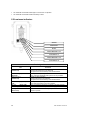
1
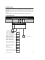
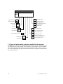
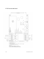
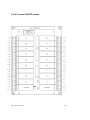
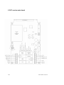
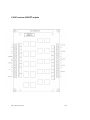
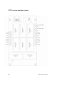
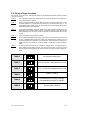
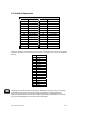
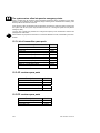
RADIO REMOTE CONTROL
M550L
User’s Manual
The reproduction of any part of the present handbook, under any form, without Imet express written
authorisation is forbidden. IMET reserves the right to modify the contents of this manual without notice. Every possible care has been taken in compiling and verifying the documentation contained in
this manual: however, Imet declaims any responsibility deriving from its use or any errors or omissions
in the information. Furthermore, IMET can not be held responsible for damages or problems in general
arising from the use of non-original Imet accessories or spare parts. The same remark applies to
persons or companies involved in the realisation of the present handbook..
M550L.doc 3° Edition – 27th January 2004
IMET S.r.l. via Fornace n.° 8, 33077 Sacile (PN) Italy
Tel +39.0434.7878 Fax +39.0434. 737848
INTRODUCTION
This manual contains detailed instructions for the installation, use and maintenance of the M550 radio
remote control family. In order to obtain the best possible performance during its operation, in complete safety, all operators must read the instructions provided in this manual carefully and follow them
scrupulously.
All operations regarding the installation, use and maintenance must be performed by specialised personnel only.
The enclosed sheets A, B and C have to be considered an integral part of this manual.
1 Identification data
Industrial radio remote control
Date of installation
Year of construction
Serial no.
TRANSMITTING UNIT ID
M550
Single transmission
S
Double transmission
D
Receiver combined with pushbutton
(12 buttons + Start and Stop)
WAVE L12
Receiver combined with pushbutton
(10 buttons + Start and Stop)
WAVE L10
Receiver combined with pushbutton
(8 buttons + Start and Stop)
WAVE S8
Receiver combined with pushbutton
(6 buttons + Start and Stop)
WAVE S6
Receiver combined with pushbutton
(4 buttons + Start and Stop)
WAVE S4
Transmitter with 4 bi-axial joystick s
G4
Transmitter with 3 bi-axial joystick s
G3
Transmitter with 2 bi-axial joystick s
G2
Transmitter with selectors and
potentiometer
S2
Transmitter with selectors
S1
Transmitter with 6 single-axial joystick s
Z6
Transmitter with 2 single-axial joystick s
Z2
IMET - M550Luk Inst manual
nnnn Project reference number
1/26
RECEIVING UNIT ID
M550
Single transmission
S
H
Cable-clamp output
Double transmission
D
I
pre-cabled output with
boxed multipolar plug
L
Pre-cabled output with cable
and multipolar plug
L
Integrated board
Slot board
H
DIN - rail
M
M
Unwired output
AC power supply
AC
A
24 Vac power supply
DC power supply
DC
B
48 - 55 Vac power supply
D
110 Vac power supply
E
230 Vac power supply
F
Power supply voltage range:
24 / 48 - 55 / 110 / 230 / 230 Vac
G
12 - 28 Vdc power supply
Project reference number
nnnn
External antenna
O
Internal antenna
I
1.1 Types of radio remote controls specified in this manual
The M550 family is made up of many different radio control versions. Some are characterised by the
use of digital controls (on/off), whereas others enable two control typologies to be used simultaneously, both analogue and digital together. This manual deals with the receiver versions L-AC and LDC. The easy identification code, given in the table above, means the configuration of the product and
can be easily recognised.
2/26
IMET - M550Luk Inst manual
INDEX
Paragraph
1
1.1
2
3
4
4.1
5
5.1
5.2
5.3
5.4
5.5
5.6
5.7
5.8
6
6.1
6.2
6.3
6.4
6.5
6.6
6.7
6.8
7
8
8.1
9
9.1
9.2
10
10.1
10.2
10.3
10.4
11
12
13
EnclosureA
EnclosureB
EnclosureC
Page
Introduction….……………………………………………………………………….….……….… 1
Identification data…..………………………………………………………………….…………. 1
Types of radio remote controls specified in this manual.………………………………………. 2
Conventions used in this manual………………………………………….…………………… 4
Operation description………….…………………………………………………………………. 4
Common applications……………………………………………………………………………. 5
Non-admitted uses……………………………………………………….………..……………….. 5
Instructions for use…………………..………………………………………...………….……… 5
Safety rules to be complied with…….……………………………….……….………….……….. 5
Start function…….……………………………………………………………….….……….……… 5
Emergency function…………………………………………………………….….……………….. 5
Switching off…………………………………………………………………..….………………… 5
Self switching off…………………………………………………………………………………... 5
Luminous indicators……………………………………………………….………………………
6
Battery state indicator…………..………………………………………….……………………… 7
Battery replacement and charging……………………………………….……………….……… 7
Criteria for a perfect installation……….……………………………………………….……… 7
Drilling plan for receiver fastening…………………………………………………..…….……… 8
Connection….…………………………………………………………………………..…………... 8
AC receiver main board………………………………………………………………..…………... 10
AC receiver ON/OFF outputs…………… ………………………………………………………... 11
DC receiver main board………………….…………………………………………..…………….. 12
DC receiver ON/OFF outputs…………………………….………………………………………... 13
DC receiver analogue outputs……………….……………………………………...…………….. 14
Set up of logic functions…………………………………………………………………….……... 15
Technical specifications …………………….-…………………………………………………. 16
Instructions for frequency change……………………………………………………………
20
Available frequencies………………………………………………………………….……...…..
21
Instructions for preventive maintenance…...……………………………………………….
22
Periodical maintenance to be carried out by the operator…………………………….……… 22
Maintenance and internal controls……………………………………………….……….……… 22
Instructions to be complied with in case of inconveniences……………….…….……… 23
List of transmitter spare parts…………………..………………………………….…….……….. 24
List of AC receiver spare parts………………………………………….………………………… 24
List of DC receiver spare parts……………….………………………………………………….. 24
Technical assistance……………………………………………………………………………….. 25
Scrapping…...………………………………………………………………………………………. 25
Coupling telegram description…………………..……………………………………………... 25
Declaration of conformity………………………………………………………………………... 26
Configuration of electric symbols of transmitter actuators…………………….…….…... A
List of commands… ………………………………………………………...…………….……… B
Wiring diagram of receiver outputs……………………..………………………….…….….… C
IMET - M550Luk Inst manual
3/26
2. CONVENTIONS USED IN THIS MANUAL
Attention
This symbol means: instructions to be complied with for a correct working of the radio remote control.
Danger
The paragraph marked with this symbol contains information to be complied with carefully to avoid
dangerous situations.
Note
This arrow means: remarks containing suggestions for a radio remote control use.
3. OPERATION DESCRIPTION
The M550 system is the result of IMET long experience in the field of radio remote controls.
The high technology applied has enabled to manufacture a product enhancing the main properties of a modern radio remote control.
Thanks to its compact anti-collision plastic container, the M550 system can stand the heaviest use
conditions with the highest reliability.
Equipped with a removable and rechargeable battery, available in the version with exclusive waterproof locking-in system, for the transmitting units type S, G and Z, and in the hermetic version with
gold plated contacts for models type WAVE, IMET radio remote control assures operation for continuous working shifts in the most climatic and environmental conditions.
A practical, clear and ergonomic control panel allows complete control of all the machine’s functions,
letting the operator perform even the most difficult manoeuvres safely and freely.
The M550 system is equipped with a frequency synthesis radio (PLL) allowing to change the
transmission channel frequency directly from the control switchboard.
A double decoding channel allows to obtain very high safety levels thus reducing error probability in
practice to zero.
Thank to the safety STOP function the system is able to operate in compliance to the most strict existing safety norms. The homonymous relays, opportunely connected, grants, when releasing a command, the safety function in case of failures (UNI-EN 954-1 norm). The safety category of each command is stated in the enclosure B and depends also from the safety STOP function, which allows to
decrease of one level the safety category of the command. This system can grant a high safety level
in dangerous situations, where a higher safety category is required.
The wide range of versions available can meet all user’s requirements. Easy to install, the radio remote control IMET M550 can be integral part of each machine, requiring a wireless command system.
It can be supplied with a cable clamp or a multiple connector fixed on the receiver case or with precabled outputs through a multiple plug. The system can operate using both during current (12÷28
Vdc) or alternate current (24, 48, 55, 110 e 230 Vac).
4/26
IMET - M550Luk Inst manual
4. COMMON APPLICATIONS
The most common applications of the radio remote control generally regard hoisting and hauling machines as construction cranes, bridge cranes, truck mounted cranes and concrete pumps. Other applications are not to be excluded, as long as they are in compliance to the conditions mentioned on
the chapter below.
4.1 Non-admitted uses
The radio remote control may not be used if the climatic and electric characteristics mentioned in the chapter 7.O are not present. Moreover, the radio remote control application is forbidden in places requiring antideflagration characteristics.
Deleted: CORRETTO E SICURO
5. INSTRUCTIONS FOR USE
For the correct radio remote control use it is necessary to comply with the rules described below,
which are essential for work safety.
5.1 Safety rules to be complied with
The radio remote control use is allowed to competent operators, who should have a perfect knowledge of the radio remote control operation and of the relative machine. IMET strictly recommends
to arrange a proper training for all operators using the radio remote control.
It is forbidden to switch on the transmitter in places where the machine, commanded through the radio remote control, is not completely visible. By switching on the transmitter in a closed place or, in
any case, far from the receiver, it is evident that it is not possible to be really aware of the operations to be carried out. This can bring to dangerous situations.
In case of work suspension, even for short periods, the control unit has to be switched off and the key
removed from the transmitter, thus to avoid its use by non allowed personnel.
5.2 Start function
• Make sure that the transmitter is switched off and the key selector is in anticlockwise position (type
S, G and Z), or that the key with reed contact has been removed from its seat (type WAVE).
• Insert a loaded battery in the transmitter.
• Make sure that the mushroom-head button for emergency is not switched on.
• Feed the machine and the receiver (remember that it takes approx. 3 seconds to the receiver to be
ready for the operation, as it carries out some safety check tests before).
• Switch on the transmitter by turning the key in the clockwise direction (type G, S, and Z), or inserting the key with reed contact in the its seat (type WAVE).
Press the START button ; The green light on the transmitter will be continuously lit when operation
is correct. From now on, it is possible to carry out the desired commands. The transmitter may not be
started when the battery is not sufficiently charged, the emergency push button is pressed or any
key is pressed during the start phase.
5.3 Emergency function
Press the red mushroom-head button; this action will stop immediately the machine and all commands. To restart operation, restore the emergency stop button operation.
5.4 Switching off
Press thoroughly the emergency stop button. The transmitter is switched off and the receiver stops.
5.5 Self switching off
IMET - M550Luk Inst manual
5/26
•
The transmitter is switched off after approx. 3 seconds of no operation.
•
The transmitter is switched off when the battery is down.
5.6 Luminous indicators
WORKING
POWER SUPPLY
RF BUSY
PASSIVE EMERGENCY CH. A
DATA ERROR CH. A
PASSIVE EMERGENCY CH. B
DATA ERROR CH. B
Receiving unit
Led
Data error ch. B
(Yellow Led)
Passive emergency ch. B
(Red Led)
Data error ch. A
(Yellow Led)
Passive emergency ch. A (Red
Led)
RF busy
(Green Led)
Power Supply (Green Led)
Working
(Green Led)
6/26
Indication
Normally switched on when operating.
It is off in case of data errors on channel B.
The system errors are showed by some decoded blinks..
Normally off when operating.
It is on when the channel B of the system is in stop condition.
Normally on when operating.
It is off in case of errors on channel A.
The system errors are showed by some decoded blinks..
Normally off when operating.
It is on when the channel A is in stop condition.
When on it shows the presence of a signal on the radio channel.
When on it means that the system is under supply.
When on it means that the 2 safety relays are closed. Now it
possible to operate.
IMET - M550Luk Inst manual
Transmitting Unit
Led
Green Led
Indication
When on it shows that the system is working.
When blinking at regular intervals means that the battery is down.
During the set up procedure of the analogue scales it gives some
decoded blinks.
In case of an anomaly in the emergency stop circuit it starts blinking in
according to a specific modality (see chapter 10)
In case of a system error it gives some decoded blinks
5.7 Battery state indicator
The battery state indicator is showed by a luminous indicator placed on the transmitter, normally lit
during operation. When the battery enters the reserve phase, it starts blinking. When the battery is
completely down, the transmitter is switched off according to the procedure described by chapter 5.4.
The reserve phase lasts approx. 15 minutes.
During the reserve phase, place immediately the machine in safety position before replacing the battery.
5.8 Battery replacement and charging
Switch off the transmitter and remove the battery, introduce it into the battery charger and wait for
the charging completion ( 2 - 3 hours).
The battery charger blinks 4 times (pre-charging) when introducing the battery, then the charging
phase starts. To confirm this, the LED is continuously lit. When recharging a battery which is completely down, it is possible that the blinking phase (pre-charging) lasts much longer. Anyway, it is followed by the real charging phase.
To assure a better efficiency and a longer life of a battery, we suggest to make use completely of
a charge, which is signalled on the transmitter by the blinking led.
Caution: do not break off the charging by removing the battery from its housing or switching off the
battery charger when the signalling LED is still on.
Abstain, as far as possible, from recharging a battery completely or partially charged.
The battery charger has been conceived for use in buildings, therefore it should be protected
against atmospheric agents. The battery recharging should be carried out in rooms without humidity and at a temperature ranging from 0 to +35° C.
6. CRITERIA FOR A PERFECT INSTALLATION
The radio remote control installation does not imply any particular difficulty. Anyway, for a good system operation, it is important to comply carefully with the rules described below.
• The installation should be carried out exclusively by qualified personnel.
• Do not elude the existing machine safety systems and comply with any manufacturer’s instruction.
• Install the receiver in vertical position, in an accessible place without metal obstacles which might
attenuate the radio waves reception. Moreover, abstain from installing the receiver too far from the
floor (1O-2O metres). At this height, it is possible to receive radio signals which might jam the reception of the radio signals coming from the transmitter.
• In presence of strong mechanical
the machine and the receiver.
IMET - M550Luk Inst manual
vibrations, put some
rubber shock-absorbers between
7/26
6.1 Drilling plan for receiver fastening
153 mm
162 mm
6.2 Connection
No operation has to be carried out with the appliances under tension
The radio remote control power supply must be connected down from the machine main switch. A direct connection is strictly forbidden. The switch of the distribution net must be equipped with a system
against a non-authorised closure ( padlock).
There are several possibilities of connection for the radio remote control:
9
pre-cabled, with multiple connector fixed on the receiver box.
9
With cable output, pre-cabled on the internal connectors and with mobile multiple plug.
9
To be cabled on the internal connector and equipped with a cable clamp.
The wiring between the receiving unit and the machine must never be of a “fixed” nature. At least a
part must be connected to a multiple connector which enables the control to be reset, at any time, via
cable.
The configuration of the radio control can be identified by referring to chapter 1 of this manual.
The wiring of the receiving unit to the machine must be carried out in accordance with the Regulation
EN60204. The connecting wires must have a minimum cross-section of 0.75 mm2 and be of a selfextinguishing type.
Refer to the transmitting unit controls diagram (see enclosure A) and the receiving unit wiring diagram
(see par. 6.4 and 6.6 and enclosure C) in order to determine the equivalence between the actuators of
the two units.
The wiring diagrams of paragraph 6.4 and 6.6 represent all available commands, which can be reduced in accordance to the radio remote control configuration.
The receiver can be supplied at 24, 48, 55 110 and 230V. If requested, it can be supplied for use with
continuous current at 12 ÷ 28V. Therefore particular attention must be paid to the connection of the
line voltage to the receiving unit terminal block. As far as the version of receiver in alternate current is
concerned, in order to grant effective protection, it is also essential to adjust the current value of the
fuse F13 according to the line voltage(see paragraph 6.3):
• Fuse of 0.63A delayed for tensions from 110 Vac to 230 Vac
• Fuse of 1.25A delayed for tensions from 24Vac to 48÷ 55 Vac
If at all possible, use the tips provided for terminating the conductors in such a way that the work is
carried out as expertly as possible, taking care to check the terminal screws are tightened.
8/26
IMET - M550Luk Inst manual
Each command is provided with an additional safety function ( safety STOP), activating the correspondent relays in the receiver, thus granting the safety function when releasing a command. In case
of operating failures. The safety STOP function increase on a value the safety category of the related
command (see enclosure B). For its activation, connect the relays of this command directly to the machine (if available), or in series. The risk evaluation has been based on the UNI EN 954-1 norm.
Example of a safety STOP relays wiring
Connect the emergency circuit so to command the coil of the main remote control switch of the machine, considering that the most available current tension is 5A. The safety category of the emergency circuit is 4 (UNI EN 954-1 norm).
Once the installation is complete, carry out an inspection and check that all the functions, both of the
radio control and the machine, are working properly. It is also compulsory to control the correct intervention of the stop circuit. Press the stop button during operation: the main relay switch should deactivate and disable all the controls.
Finally, fill out the card with the wiring diagram of the connection of the receiving unit to the machine
and write the date of installation in the box provided on the first page of this manual.
IMET - M550Luk Inst manual
9/26
6.3 AC receiver main board
10/26
IMET - M550Luk Inst manual
6.4 AC receiver ON/OFF outputs
IMET - M550Luk Inst manual
11/26
6.5 DC receiver main board
12/26
IMET - M550Luk Inst manual
6.6 DC receiver ON/OFF outputs
IMET - M550Luk Inst manual
13/26
6.7 DC receiver analogue outputs
14/26
IMET - M550Luk Inst manual
6.8 Set up of logic functions
The receiver can be set up by selecting the position of the Dip-Switches placed inside the receiver
(see par. 6.3 and 6.5)
Table 0:
The commands coming from the transmitter are executed without being subjected to
any conditioning by the receiver.
Table 1:
Three speeds associated with three different keys with command maintenance. Once
the basic speed key is pressed down(A1 and/or A2), the second speed (A3), or the
third speed key (A4), needs only to be pressed briefly and said functions will be maintained till the basic speed is released.
Table 2:
Three speeds associated with three different keys with command maintenance. The
description given for table 1 applies, with the only difference being, in this case, that the
basic speed keys are A5 and A6, whilst the second and the third speed keys are A7
and A8.
Table 3:
Is the combination of the two previous tables.
Table 4:
Three speeds associated with just 2 keys with memory. In this case, the dual function of
the key is exploited allowing the basic speed to be obtained when pressed once and
the second speed when pressed for the second time. The third speed is, instead, activated by another key, specifically: A3 for the A1/B5 or A2/B5 key, and A4 for A5/B7 or
A6/B7.
Table 5:
In case the radio remote control is to applied to a bridge crane, since this function requires distinct second speed controls, even the second function of each key (which
normally belongs to two adjacent keys ant is the same for both) is used as a distinct impulse.
Table 0
Table 1
Table 2
Table 3
Table 4
Table 5
ON
No automatic maintenance
OFF
1
2
3
4
1
2
3
4
1
2
3
4
1
2
3
4
ON
A3 or (A3 and A4) , maintained by A1or A2.
OFF
ON
A7 or ( A7 and A8 ) maintained by A5 or A6.
OFF
ON
Table 1 + Table 2
OFF
ON
OFF
1
2
3
4
1
2
3
4
ON
Second speed – Distinct
OFF
IMET - M550Luk Inst manual
A3 maintained by (A1+B5) or (A2+B5)
A4 maintained by (A5+B7) or (A6+B7)
15/26
7. TECHNICAL SPECIFICATIONS
•
•
•
•
•
•
•
•
•
•
•
•
•
•
•
•
•
•
•
•
•
•
Manufacturer
Working frequency
Standard
Channel spacing
Number of P.L.L. programmable radio channels
Outreach
Modulation
Receiver sensibility
Hamming distance
Error non-detection probability
Available pairing addresses
Delay time on receiver start
Delay time on the start command
Response time of commands
Response time of active emergency
Response time of passive emergency
Safety category of STOP command (UNI EN 954-1)
Safety category of movement commands (UNI EN 954-1)
Operation and storage temperature
Housing protection degree
Housing material
Quantity of safety commands
IMET S.r.l.
I.S.M. Band 433.075 ÷ 434.775 Mhz
ETSI EN 300 220-3
25 Khz Simplex, ( 25 KHz Half Duplex)*
30
≅ 100 m
GMSK Dev. 3 KHz
0.22 uV 12 dB Sinad
≥9
< 7.34x10⁻¹²
65536
< 3 sec
< 750 ms
< 110 ms, (< 120 ms)*
< 150 ms, (< 220 ms)*
< 800 ms
4(UNI EN 954-1)
3 (UNI EN 954-1) (with safety STOP)
-20°C ÷ +70°C(-4°F ÷ +158 °F)
IP 65
Charged Nylon
2 Safety Stop, Emergency stop
Transmitters type WAVE:
• Max. quantity of ON/OFF commands
• Service commands
• Max. quantity of analogue commands
• Max quantity of selector commands (optional )
16 (WAVE S), 20 (WAVE L)
1 Klaxon
1
4
Transmitters type S, G and Z:
• Max quantity of ON/OFF commands
• Service commands
20
1, ( 3 ) Start (Klaxon and Timed Stop,
optional)
• Max. quantity on analogue commands
8
* Data Feedback version
16/26
IMET - M550Luk Inst manual
Transmitting unit WAVE type:
•
•
•
•
•
•
•
•
Emission power of the R.F. system
Emission class
Oscillator type
Supply tension
Power demand
Supply power
Battery
Autonomy at 20 °C with charged battery –
continuos operation
• Advice time “battery down”
• LCD* Display
• Visualisation speed of the characters on the display
10 mW ERP (Internal Antenna)
25K0F1D
Synthesizer
2.4 Vdc
100 mA, 120mA*
0,3 W*
Ni-MH 2,4V 1.5 A/h
≅ 15 hours , 12 hours*
≅15 min
2 lines of 8 characters each
(30x15mm)
100 char/sec
Transmitting units type S, G and Z:
•
•
•
•
•
•
•
•
Emission power of the R.F. system
Emission class
Type of oscillator
Supply tension
Current demand
Power demand
Battery
Autonomy at 20 °C with charged battery –
continuous operation
• Advise time “battery low”
• LCD* Display
• Visualisation speed for the characters on the display*
10 mW ERP (Internal antenna)
25K0F1D
Synthesizer
6 Vdc
90 mA, 110mA*
0,54 W, 0,66 W*
Ni-MH 6V 1 A/h
≅ 11 hours , 9 hours*
≅15 min
2 lines of 16 characters each
(55x15 mm)
100 char/sec
• Dimensions:
type WAVE S
type WAVE L
type S1, S2
type G2, G3
type Z2
type Z6
75x43x180 mm (L.P.H.)
75x43x245 mm (L.P.H.)
175x115x135 mm (L.P.H.)
235x177x175 mm (L.P.H.)
205x115x170 mm (L.P.H.)
196x137x170 mm (L.P.H.)
type WAVE S
type WAVE L
type S1
type S2
type G2
type G3
type Z2
type Z6
≅0,375 Kg
≅0,465 kg
≅1,050 Kg
≅1,200 Kg
≅1,650 Kg
≅1,800 Kg
≅ 1,200 Kg
≅ 1,350 Kg
• Weight :
* Data Feedback version
IMET - M550Luk Inst manual
17/26
Receiving unit:
• RF receiver type
•
•
•
•
Emission power of the R.F. system
Emission class *
Oscillator type *
Supply tension
•
•
•
•
•
Power demand
Max. quantity of command relays (NO)
Max quantity of command relays (NC/NO)
Max. quantity of DC command drivers
Max. quantity of service relays (NO)
Superetherodine IF 83.16 MHz 455KHz
10 mW ERP (Internal antenna)
25K0F1D
Synthesizer
24 Vac, 48 ÷ 55 Vac, 110 Vac, 230 Vac,
12 ÷ 28 Vdc
15 W Max
16
4
20
3
• Max. carrying capacity of AC receiver command relays:
• Max. carrying capacity of DC receiver command relays
10A 130V - AC1
6A 28V (resistive load pure L=0)
2A 28V (inductive load L =10 mH)
• Max. carrying capacity of AC receiver start relays
• Max. carrying capacity of DC receiver start relays
12A 130V - AC1
12A 28V - DC1
• Max. carrying capacity of AC klaxon relays (relays C3)
• Max. carrying capacity of DC klaxon relays
12A 130V - AC1
12A 28V - DC1
• Max. carrying capacity of AC timed stop (C4 relays)
• Max. carrying capacity of DC timed stop
12A 130V - AC1
12A 28V - DC1
• Max carrying capacity of AC safety STOP relays
• Max carrying capacity of DC safety STOP relays
6A 130V - AC1
6A 28V - DC1
• Max. carrying capacity of AC receiver stop relays
• Max. carrying capacity of DC receiver stop relays
6A 130V - AC1
6A 28V - DC1
• PWM analogue output
• Analogue output with loop of current
• Analogue output in tension
0 ÷ 1.4 A MAX
0 ÷ 20 mA o 4 ÷ 20 mA
25% Vcc, 50% Vcc, 75% Vcc
0 ÷ ( Vcc-3) adjustable, MAX 28V
•
•
•
•
•
•
Serial / Parallel
8
4
50000 char/sec
15000 char/sec
4800/9600 bit/sec
Input ports*
Max quantity of digital inputs*
Max. quantity of analogue inputs*
Data exchange speed of the parallel port*
Data exchange speed of the synchronous serial port*
Data exchange speed fo the asynchronous serial port*
• Dimensions
• Max. weight
145 X 65 X 225 mm ( L.P.H)
1,7 Kg
* Data feedback version
18/26
IMET - M550Luk Inst manual
Battery charger CB5000 for WAVE Models:
•
•
•
•
•
•
•
•
•
•
•
Supply tension
Power demand
Charging current
Max. charging time
Charge type
Housing protection degree
Storage temperature with loaded battery
Storage temperature off and without battery
Dimensions
Weight
Weight with 230Vac transformer (optional)
11÷32Vdc. Optional 230Vac
4W while charging
550mA
3 hours
PVD
IP30
0°C ÷ +35°C ( +32°F ÷ +95 °F)
-20°C ÷ +70°C (-4°F ÷ +158 °F)
75X49X142 mm (L.P.H.)
250g
490g
Battery charger CB6000 for S, G and Z models:
•
•
•
•
•
•
•
•
•
•
•
Supply tension
Power demand
Charging current
Max. charging time
Charge type
Housing protection degree
Operation temperature with loaded battery
Storage temperature off and without battery
Dimensions
Weight
Weight with transformer 230Vac (optional)
IMET - M550Luk Inst manual
11÷32Vdc. Optional 230Vac
3W (while charging)
450mA
3 ore
PVD
IP30
0°C ÷ +35°C ( +32° F ÷ +95° F)
-20°C ÷ +70°C (-4°F ÷ +158 °F)
137x94x260 mm (L.P.H.)
250g
620g
19/26
8. INSTRUCTIONS FOR FREQUENCY CHANGE
The frequency change can be carried out for all models using two commands belonging to group A,
(A1 - A8 for the joystick- for the tens, A2 for the units) and the button START
(see enclosures A
and B). There are two different modalities at disposal: through the movement of the frequency channel
in use to the second subsequent one ( modality “two steps”) , or through the selection of a precise
working channel (modality “any step”). If the selected channel should not be available, it is necessary
to repeat the frequency change procedure till to find a channel free from any interference.
Frequency change - Modality “two steps”.
9
Position the transmitting unit as close a possible to the receiver. Power up the receiver and turn
the transmitter’s key clockwise (ON position).
9
Activate the commands A1 and A2 simultaneously (A8 for the joystick) and A2 (see enclosure A
for the identification), press the START . The ignition light placed on the transmitting unit should
blink 4 times consecutively followed by a pause.
9
Release the two commands and the START
9
Push the START
and check if the led placed on the transmitter blinks at regular intervals.
Wait more or less 20 seconds, till the green light stops blinking and goes off. The system can now
operate on the new frequency channel.
9
it is possible to carry out the commands. If not, this means that
By pressing again the START
a mistake has been made during the execution of the procedure. Switch off the system and repeat
the operation from the beginning.
.
Frequency change - modality “any step”.
9
Place the transmitter as close as possible to the receiving unit. Power up the receiver and turn the
transmitter key clockwise (ON position).
9
Actuate the commands A1 (A8 for the joystick) and A2 (see enclosure A for the identification) simultaneously, press the START . The ignition light on the transmitting unit should start blinking
4 times consecutively followed by a pause.
9
Release the two commands and the START
9
Select one of the 69 available channels, by using A1 (A8 for the joystick) for the tens and A2 for
the units. Example: for the push button, the channel 36 is selected by activating 3 times the command A1 (tens) and 6 times the command A2 (units).
9
to confirm and check whether the green light place on the transmitter is blinking
Press START
at regular intervals. Wait more or less 20 seconds, till the led stops blinking and goes off. Now the
system is ready to operate on the new frequency channel.
9
By pressing again the START , it is possible to carry out the commands. If not, this means that
a mistake has been made during the execution of the procedure. Switch off the system and repeat
the operation from the beginning.
.
The selection of the frequency channel is limited to number 3 for the tens (command A1 (A8 for the
joystick)) and to number 9 for the units (command A2).By activating more than 3 times the tens, or
more than 9 times the units, the counting begins again from 0.
To select “zero”, it is not necessary to activate the command. For ex. For channel 20, select 2 times
to confirm the operation.
the command A1 and press START
NOTE: Selecting 3 for the tens, the units, even if of different value, will be always zero. By selecting
channel 00, the frequency will change according to the “two steps” modality.
20/26
IMET - M550Luk Inst manual
8.1 Available frequencies
Table of available frequencies
CHANNEL
01
02
03
04
05
06
07
08
09
10
11
12
13
14
15
FREQUENCY
434.050 MHz
434.075 MHz
434.100 MHz
434.125 MHz
434.150 MHz
434.175 MHz
434.200 MHz
434.225 MHz
434.250 MHz
434.275 MHz
434.300 MHz
434.325 MHz
434.350 MHz
434.375 MHz
434.400 MHz
CHANNEL
16
17
18
19
20
21
22
23
24
25
26
27
28
29
30
FREQUENCY
434.425 MHz
434.450 MHz
434.475 MHz
434.500 MHz
434.525 MHz
434.550 MHz
434.575 MHz
434.600 MHz
434.625 MHz
434.650 MHz
434.675 MHz
434.700 MHz
434.725 MHz
434.750 MHz
434.775 MHz
Please find below all countries where the radio remote controls have been notified to the national
competent authorities on the radio frequencies spectrum , according to the art. 6.4 of the 1999/5/CE
directive.
No Country
Austria
1
Belgium
2
Denmark
3
Finland
4
France
5
Germany
6
Greece
7
England
8
Ireland
9
10 Italy
11 Luxembourg
12 Liechtenstein
13 Holland
14 Portugal
15 Spain
16 Sweden
17 Norway
18 Switzerland
19 Hungary
The product can be sold in all countries belonging to the European community, acting in accordance
to the ERC REC 70-03 norms. Each single Country can provide then for special restrictions or
licenses of use, determined by the national competent authorities on the management of the
telecommunications spectrum. For this reason, before using the radio remote control, it is necessary
to get more acquainted with the current laws concerning this matter.
IMET - M550Luk Inst manual
21/26
9. INSTRUCTIONS FOR PREVENTIVE MAINTENANCE
Some suggestions for a correct maintenance of your radio remote control.
• Do not expose to heat sources.
• Avoid exposure to sun for long periods.
• Do not wash with high pressure jets or immerse appliances into water.
• Avoid contact with oil and solvents.
• If the appliances are open, and make sure that the gaskets are tight.
Submit the radio remote control to regular cleaning and check operations to keep it efficient and safe.
Before starting the maintenance operations, switch off the receiver and the machine and remove
the battery from the transmitter.
Use a brush and a wet cloth to carry out cleaning operations. Do not use alcohol or solvents, as
they might damage components and radio remote control housing.
9.1 Periodical maintenance to be carried out by the operator
Clean periodically all external parts of the receiver and the transmitter. Material settlement may stop
push buttons movement.
Pay particular attention to the emergency button, clean it carefully and check whether it moves without
any difficulty.
Remove any oxidation form the battery contacts.
Check the integrity of the radio remote control housing and components. They may not have any
creeks or even evident breaking.
All rubber parts, keys and gaskets must be free form tearing.
If you find any damaged components, replace them immediately to prevent humidity penetration and
impurities from jeopardising safety and the perfect radio remote control operation.
9.2 Maintenance and internal controls
After one year of operation, carry out a careful internal maintenance of the radio remote control units.
Said checks shall be carried out by specialised personnel.
Before opening the appliances, switch off the receiver and the machine and remove the transmitter
battery. The operations described below should be carried out in a place free from dust and humidity.
Open the transmitter and receiver housing and check:
• The tightness of the gaskets.
• The cable connectors tightening.
• The screws tightening of the connection clamps and the connectors clutch.
• The tightening of the electronic cards.
• The tightening of the screws of the connection clamps and the integrity of the battery contacts.
Although well tight, dust and humidity can enter the radio apparatus . In this regard, we reccomend to
remove carefully any foreign particles.
22/26
IMET - M550Luk Inst manual
Reassemble the transmitter, making sure that it is well closed to avoid humidity infiltration.
When appliances are on, do not touch the parts under voltage of the receiver and carry out the following test:
• Check the correct operation of all commands
• Check the correct intervention of the emergency stop circuit. Press the emergency stop button
while working; The machine main contactor circuit will be interrupted stopping all commands.
All faulty parts shall be replaced through original spare parts so that the system properties are not altered. See list of spare parts par. 10.1, 10.2
In the end, close the receiver and make sure that the gasket has perfect tightness.
10. INSTRUCTIONS TO BE COMPLIED WITH IN CASE OF
INCONVENIENCES
The present chapter explains some problems which may occur during the radio remote control use
and tries to give, for each problem, a possible solution.
Firstly, make sure if the failure is given by the radio remote control and replace it through a traditional
cable control to check whether the machine operation is correct.
All repairs shall be carried out in compliance with the manufacturer's instructions. Any faulty parts
shall be replaced through original spare parts so that the system properties are not altered. (see
the list of the spare parts par. 10.1, 10.2 e 10.3).
Before carrying out any internal intervention, switch off receiver and machine and remove the battery from the transmitter.
We suggest to carry out a general check according to the following instructions.
The transmitter does not come on
Switch the device on by turning the selector key clockwise and activating the start control START .
The green LED set on the transmitter should light up. If this is not the case, replace the battery in use
with a charged one and check the presence of oxidation on the contacts. No commands (including the
emergency button) have to be activated.
If after pressing the START , the green Led begins blinking very fast, this shows a failure in the
emergency circuit. If after this operation the led begins giving a series of 8 short blinks (zero code),
the circuit is working correctly, while on the contrary, the led will produce a failure code. In this case
we suggest, for safety reasons, to avoid to start again the system, and to apply to a authorised assistance centre to solve the problem.
The receiver does not come on
Power Supply LED is off:
• Check the fuse F10 placed inside the receiver.
• Check the connection between the machine and the radio remote control.
• Check if the machine feeds correctly the receiver;
The receiver comes on but does not activate the machine main
contactor
Check the F12 fuse status.
IMET - M550Luk Inst manual
23/26
The system enters often into passive emergency status
Such a condition may be caused by other transmitters positioned nearby, transmitting on the same
frequency. This hypothesis can be verified by simply switching off the transmitter and checking if the
RF-busy LED on the receiver remains lit.
If the device is subject to interference during operation, the Data Error LED may switch off every time
the system finds an error (errors may last more than 0.5 sec., sending the system into the passive
emergency state).
The only way to avoid such problems is to change the frequency of the transmission channel. See
paragraph 8 for instructions.
Other troubles may require the intervention of a technical assistance centre, authorised by the manufacturer.
10.1 List of transmitter spare parts
Description
Article
Reed contact key
Key for rotary selector
Shoulder belt
CB5000 230 Vac battery charger with Italian plug
CB5000 230 Vac battery charger with Shuko plug
CB5000 11 ÷ 32 Vdc battery charger
2.4V 1.5 A/h Ni-MH battery
CB6000 230 Vac battery charger with Italian plug
CB6000 230 Vac battery charger with Shuko plug
CB6000 11 ÷ 32 Vdc battery charger
6V 1 A/h Ni-MH battery
AS038
AS015
AS013
CR010
CR012
CR011
AS037
CR008
CR009
CR007
AS034
10.2 AC receiver spare parts
Description
F10 fuse 5x20 T 1,25A delayed
F11 fuse 5x20 T 5A
F12 fuse 5x20 T 5A
Article
F13 24÷55V fuse 5x20 T 1,25A delayed
FS002
FS005
FS005
FS002
F13 110÷230V fuse 5x20 T 0,63A
FS001
10.3 DC receiver spare parts
Description
F10 fuse 5x20 T 1,25A delayed
F11 fuse 5x20 T 5A
F12 fuse 5x20 T 5A
24/26
Article
FS002
FS005
FS005
IMET - M550Luk Inst manual
10.4 Technical assistance
In all cases of a real radio remote control failure, which is not possible to detect on a superficial check,
like the checks suggested in the present handbook conceived for non-specialised personnel, apply exclusively to the assistance service centre authorised by the manufacturer.
Get in contact with the nearest assistance centre or the reseller where you bought the radio remote
control and tell him the following data:
• Radio remote control model.
• Serial Number.
• Detected problem.
• Purchase date.
Remember that the present handbook and the warranty certificate filled in all parts.
11. SCRAPPING
When the radio remote control cannot be used any longer, remove batteries and hand it over to the
area disposal centre.
It is absolutely forbidden to throw batteries into the city wastes containers, as they are strongly
polluting. Therefore, if necessary, throw them into the special containers.
12. COUPLING TELEGRAM DESCRIPTION
The constant length telegram is composed by 127 bits, 16 of which are assigned to the coupling address between transmitter and receiver, 83 of which are used for the command code, while the remaining 28bits implement the protection algorithm, assuring a Hamming distance of 9, with a probability of non-detection error of 7.34 x 10⁻¹², both for the address and the command code.
The 16 address bits are used to couple the transmitting unit to the receiver through a single code,
which is adjusted in the coupling electronic card and assigned exclusively to each radio remote control.
IMET - M550Luk Inst manual
25/26
13. DECLARATION OF CONFORMITY
Industrial radio remote control IMET model M550
Serial no.
Construction year 2004
Is suitable
for installation on machines or other apparatus in conformity with the “Machine Directive 98/37 CE”
Is in conformity with the following standards / or technical
specifications
• EN 330 220-3 (2000)
(Standard SRD)
• EN 301 489-1 (2001)
(Standard EMC)
• EN 301 489-3 (2002)
(Standard EMC)
• EN 61000-6-2 (2001)
(Standard EMC)
• EN 61000-6-4 (2001)
(Standard EMC)
• UNI EN 954-1 (10-1998)
(Parts of the command system dealing with safety)
• EN 60204-32, 1998-10
(Machinery safety)
Electric equipment of the machines – Part 32 : Requirements for hosting equipment
•
EN 60950 (2000)
(Safety in Information technology)
Which assign to the protection requirements stated by the
CEE Directives
• 1999/5/CE acknowledged by the LEGISLATIVE DECREE 9th May 2001, No 269 (Directive
R&TTE)
• 89/336/CEE, article 4, 10.1 and 10.2. Enclosures I and III (Directive EMC)
• 73/23/CEE, article 2, Enclosures I, III Part B and IV and following variations(Directive LV)
Sacile, 27th January 2004
IMET S.r.l.
The President Evio Cadorin
26/26
IMET - M550Luk Inst manual