1
I N V E RT E R
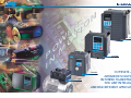
GVX2000
TYPE
APPROVED
TÜV Rheinland
Product Safety
C
®
®
BAUART
GEPRÜFT
INNOVATION IN THE
WAKE OF TRADITION
N
O
RI
ET
WO
OM
P
N
I
GVX900
0.2-4 kW
COMPLETE AND
ADVANCED SOLUTIONS
IN POWER TRANSMISSION
FOR ANY INTELLIGENT
AND HIGH EFFICIENT APPLICATION
GSX600
0.4-2.2 kW
LMS
0.4-4 kW
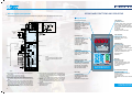
GVX2000
0.55-500 kW
N
O
RI
ET
WO
OM
P
N
I
GVX900
0.2-4 kW
COMPLETE AND
ADVANCED SOLUTIONS
IN POWER TRANSMISSION
FOR ANY INTELLIGENT
AND HIGH EFFICIENT APPLICATION
GSX600
0.4-2.2 kW
LMS
0.4-4 kW
GVX2000
0.55-500 kW
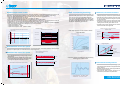
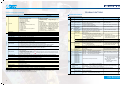
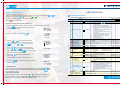
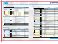
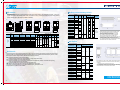
Dynamic torque-vector control
IGBT soft switching technology
Advanced, convenient functions
Dynamic torque-vector control system performs high-speed calculation to determine the required motor power for the
load status. Our key technology is optimal control of voltage and current vectors for maximum output torque.
• The torque values obtained with an inverter GVX2000 for high performances applications are:
• 250% of rated motor torque on short period
• 200% of rated motor torque at 0.5Hz (180% for models over 30kW)
• Achieves smooth acceleration/deceleration in the shortest time for the load condition.
• Using a high-speed CPU, quickly responds to an abrupt load change, detects the regenerated power to control the
deceleration time. This automatic deceleration function greatly reduces the inverter tripping.
• Feedback control with PG, enables the inverter to execute “vector control with PG” by adding an optional PG feedback
card to obtain higher performances of starting torque and control precision:
• Speed control range: 1:1200
• Speed control accuracy: ±0.02%
• Speed control response: 40Hz - (25kW or smaller)
The GVX2000 series inverter utilizes improved new
generation IGBT power devices, with the gate controlled
by the new soft-switching commutation techniques.
This increases the pulse switching time, reducing the
motor peak voltage and prolonging the motor insulation
life, without using additional output filters or reactors
and without compromising performances.
• 16-step speed, 7 pattern operation with timer control,
rotating motor pick-up control for conveyance machinery.
• Automatic energy-saving operation, PID control, cooling
fan on/off control, line/inverter changeover operation
for fans and pumps.
• Rotating motor pick-up control: restarts motor without
any shocks, by detecting motor speed where motor is
coasting after momentary power failure occurs.
• Automatic energy-saving operation function: minimizes
inverter and motor loss at light load.
PG Vector Control
Torque characteristics with Dynamic torque-vector control
(sample: 5.5 kW)
Peak voltage reduction at motor terminals in relation
to the cable length
300
100
Actual torque [%]
200
Output torque [%]
Rotating motor pick-up control characteristics
(sample: 5.5 kW)
Step load response (sample : 5.5 kW)
Power source
0
Motor speed
[r/min]
100
100
Torque reference
0
0
1000
2000
[%]
400
Motor speed
[r/min]
100
Output current [A]
500
Motor speed [r/min]
200
Time
10
0
300
Time
Energy saving effect
320ms
100
Required power [%]
Reduced motor wow at low speed
Motor wow at low speed (1Hz) reduced to less than 1/2 of that achieved by conventional inverters, with the dynamic
torque-vector control system, in combination with the unique digital AVR.
Reduced motor wow at low speed
• On-line tuning to continuously check for variation of
motor characteristics during running for high-precision
speed control.
• This tuning function also available for a second motor,
which allows high-precision driving of the second motor
by changeover operation between two motors.
Wow characterisics (sample: 5.5 kW)
Previous Series Inverter
0
With on-line tuning
Inverter control
(Automatic energy-saving
control)
Flow rate [%]
100
GVX2000
5 r/min
Time
°
Temperature [C]
Motor speed [r/min]
30°C
Energy
saved
Comparison between a GVX2000 drive with soft-switching
technology and a traditional drive
0
70°C
Inverter control
(V / f control)
14 r/min
0
Motor temperature vs speed variation (sample: 5.5 kW)
5,5 kW
Damper
control
500ms
Environment-friendly features
• Provided with low-noise control power supply systems
which minimize noise interference on peripheral devices
such as sensors.
• Equipped with terminals for connecting DC REACTOR
that can suppress harmonics.
• Complied with EMC Directive (Emission) when
connected to optional EMC-compliance filter.
Without on-line tuning
0
2
Time [min]
80
GVX2000
3
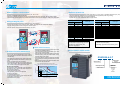
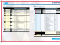
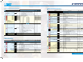
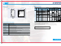
Global products, communication
Extensive product line
• Conforms to major world safety standards: CE, UL, cUL, TÜV, C-Tick.
• Equipped with RS485 interface as standard.
• Connection to field bus: Profibus-DP, Interbus-S, DeviceNet, Modbus Plus and others, with the ANY-BUS option.
• Universal DI/DO: monitors digital I/O signal status and transmits to a host controller, helping to simplify factory automation.
• Since the product is equipped with a dual rating feature, it can be used for standard applications (fan, pumps,
conveyors, multimotor application) as well as high performance applications (load rising or lifting).
• Totally-enclosed casing (IP40) (up to 25kW as standard).
• Optional IP20 enclosure available for 30kW or larger models.
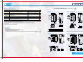
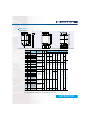
Applicable motor
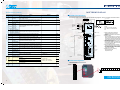
Intelligent Keypad panel
• Copy function: easily copies function codes and data to other inverters.
• Six languages (English, French, German, Italian, Spanish, and Japanese) are available as standard.
• Jogging (inching) operation from the Keypad or external signal
• Remote operation using optional extension cable (1,5 to 10m)
RUN
RUN
GVX2000
Dangnous voltage unil change light bolt
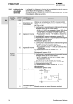
Protective functions, Maintenance
Protection
• Motors with various characteristics can be used by
setting thermal time constant for the electronic thermal
overload relay.
• Input phase loss protective function protects the inverter
from damage caused by disconnection of power supply
lines.
• Motor is protected with a PTC thermistor.
• Input terminals for auxiliary control power supply (2.2
kW or larger models) : alarm signal output will be held
even if main circuit power supply has shut down.
Excellent maintainability
The items below can be monitored on the Keypad panel
and making it easy to analyze the cause of trip and to
take preventive measures.
• Input/output terminals check
• Life expectancy of main-circuit capacitors
• Inverter on-load factor
• Accumlated operation time
• Inverter operating condition (output current, heat sink
temperature, input power, etc.)
• Detailed data on trip cause
4
0,55
1,1
2,2
3,0
5,5
7,5
11
15
18,5
22
25
30
37
45
0,4
0,75
1,5
2,2
4,0
5,5
7,5
11
15
18,5
22
25
30
37
GVX2000-0,55-T
GVX2000-1,1-T
GVX2000-2,2-T
GVX2000-3,0-T
GVX2000-5,5-T
GVX2000-7,5-T
GVX2000-11-T
GVX2000-15-T
GVX2000-18,5-T
GVX2000-22-T
GVX2000-25-T
GVX2000-30-T
GVX2000-37-T
GVX2000-45-T
Standard
applications
High performance
applications
55
75
90
110
132
160
200
220
280
315
400
450
500
45
55
75
90
110
132
160
200
220
280
315
355
400
Inverter type
GVX2000-55-T
GVX2000-75-T
GVX2000-90-T
GVX2000-110-T
GVX2000-132-T
GVX2000-160-T
GVX2000-200-T
GVX2000-220-T
GVX2000-280-T
GVX2000-315-T
GVX2000-400-T
GVX2000-450-T
GVX2000-500-T
High performance applications are considered:
- constant torque load (heavy)
- load lifting, high performance positioning (axis)
Other useful functions
• Side-by-side mounting (up to 25kW) saves space when
inverters are installed in a panel.
• The uniform height (260mm) of products (up to 11kW)
makes it easy to design panels.
• User-definable control terminals: digital input (9 points),
transistor output (4 points), relay contact output (1 point),
and alarm relay contact output.
• Active drive feature: performs prolonged acceleration
at reduced torque, monitoring the load status to prevent
tripping.
• Stall prevention function is provided as standard. Active
or inactive can be also selected.
How to read the model number
GVX2000-4.0-T
Series name
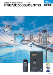
Torque characteristics with Dynamic torque-vector control
100% of output torque refers to the rated torque of the motor driven at 50Hz.
Development code
Product name
200
Output torque [%]
CAUTION
High performance
applications
Standard applications are considered:
- constant torque load (not heavy, conveyors)
- variable torque loads (pumps, fans)
- multimotor applications
WARNING
RISK OF INJURY OR ELECTRIC SHOCK
Rolor yhe user’s manual bolone instruction
and operation.
RISK OF ELECTRIC SHOK
Do not remove the cover whte oppyng
power and at cast 5 min. doconneng power
RISK OF ELECTRIC SHOCK
Scourety ground the equimpent
Standard
applications
Applicable motor
Inverter type
Continuous operation
torque
Short time operation
torque
0.55 to
2.2kW
100
90
3.0 to
25kW
Input power
source
T = Three-phase 400V
Nominal
applied motor
0,55 kW
0,75 kW
1,5 kW
to
500 kW
50
16
15 20
50
Output frequency [Hz]
100
GVX2000
5
Global products, communication
Extensive product line
• Conforms to major world safety standards: CE, UL, cUL, TÜV, C-Tick.
• Equipped with RS485 interface as standard.
• Connection to field bus: Profibus-DP, Interbus-S, DeviceNet, Modbus Plus and others, with the ANY-BUS option.
• Universal DI/DO: monitors digital I/O signal status and transmits to a host controller, helping to simplify factory automation.
• Since the product is equipped with a dual rating feature, it can be used for standard applications (fan, pumps,
conveyors, multimotor application) as well as high performance applications (load rising or lifting).
• Totally-enclosed casing (IP40) (up to 25kW as standard).
• Optional IP20 enclosure available for 30kW or larger models.
Applicable motor
Intelligent Keypad panel
• Copy function: easily copies function codes and data to other inverters.
• Six languages (English, French, German, Italian, Spanish, and Japanese) are available as standard.
• Jogging (inching) operation from the Keypad or external signal
• Remote operation using optional extension cable (1,5 to 10m)
RUN
RUN
GVX2000
Dangnous voltage unil change light bolt
Protective functions, Maintenance
Protection
• Motors with various characteristics can be used by
setting thermal time constant for the electronic thermal
overload relay.
• Input phase loss protective function protects the inverter
from damage caused by disconnection of power supply
lines.
• Motor is protected with a PTC thermistor.
• Input terminals for auxiliary control power supply (2.2
kW or larger models) : alarm signal output will be held
even if main circuit power supply has shut down.
Excellent maintainability
The items below can be monitored on the Keypad panel
and making it easy to analyze the cause of trip and to
take preventive measures.
• Input/output terminals check
• Life expectancy of main-circuit capacitors
• Inverter on-load factor
• Accumlated operation time
• Inverter operating condition (output current, heat sink
temperature, input power, etc.)
• Detailed data on trip cause
4
0,55
1,1
2,2
3,0
5,5
7,5
11
15
18,5
22
25
30
37
45
0,4
0,75
1,5
2,2
4,0
5,5
7,5
11
15
18,5
22
25
30
37
GVX2000-0,55-T
GVX2000-1,1-T
GVX2000-2,2-T
GVX2000-3,0-T
GVX2000-5,5-T
GVX2000-7,5-T
GVX2000-11-T
GVX2000-15-T
GVX2000-18,5-T
GVX2000-22-T
GVX2000-25-T
GVX2000-30-T
GVX2000-37-T
GVX2000-45-T
Standard
applications
High performance
applications
55
75
90
110
132
160
200
220
280
315
400
450
500
45
55
75
90
110
132
160
200
220
280
315
355
400
Inverter type
GVX2000-55-T
GVX2000-75-T
GVX2000-90-T
GVX2000-110-T
GVX2000-132-T
GVX2000-160-T
GVX2000-200-T
GVX2000-220-T
GVX2000-280-T
GVX2000-315-T
GVX2000-400-T
GVX2000-450-T
GVX2000-500-T
High performance applications are considered:
- constant torque load (heavy)
- load lifting, high performance positioning (axis)
Other useful functions
• Side-by-side mounting (up to 25kW) saves space when
inverters are installed in a panel.
• The uniform height (260mm) of products (up to 11kW)
makes it easy to design panels.
• User-definable control terminals: digital input (9 points),
transistor output (4 points), relay contact output (1 point),
and alarm relay contact output.
• Active drive feature: performs prolonged acceleration
at reduced torque, monitoring the load status to prevent
tripping.
• Stall prevention function is provided as standard. Active
or inactive can be also selected.
How to read the model number
GVX2000-4.0-T
Series name
Torque characteristics with Dynamic torque-vector control
100% of output torque refers to the rated torque of the motor driven at 50Hz.
Development code
Product name
200
Output torque [%]
CAUTION
High performance
applications
Standard applications are considered:
- constant torque load (not heavy, conveyors)
- variable torque loads (pumps, fans)
- multimotor applications
WARNING
RISK OF INJURY OR ELECTRIC SHOCK
Rolor yhe user’s manual bolone instruction
and operation.
RISK OF ELECTRIC SHOK
Do not remove the cover whte oppyng
power and at cast 5 min. doconneng power
RISK OF ELECTRIC SHOCK
Scourety ground the equimpent
Standard
applications
Applicable motor
Inverter type
Continuous operation
torque
Short time operation
torque
0.55 to
2.2kW
100
90
3.0 to
25kW
Input power
source
T = Three-phase 400V
Nominal
applied motor
0,55 kW
0,75 kW
1,5 kW
to
500 kW
50
16
15 20
50
Output frequency [Hz]
100
GVX2000
5
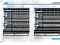
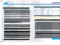
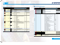
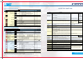
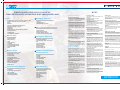
COMMON SPECIFICATIONS (0.55 - 25
Type
GVX2000-
0.55
-T
1.1
2.2
3.0
5.5
7.5
W)
11
COMMON SPECIFICATIONS
15
18.5
22
GVX2000-
25
-T
(30 - 500 W)
37
45
55
75
90
110
132
160
200
220
280
315
400
450
500
30 EV 30
37
45
55
75
90
110
132
160
200
220
280
315
400
450
30
High performance
application
1)
[kW]
Rated capacity
Output ratings
Rated voltage
Rated
current 4) 5) [A]
Torque
overload
2)
[kVA]
3)
[V]
0.55
1.1
2.2
3.0
5.5
7.5
11
15
18.5
22
25
0.4
0.75
1.5
2.2
4.0
5.5
7.5
11
15
18.5
22
1.0
1.7
2.6
3.9
6.4
12
17
21
1.9
High performance
application
3.1
1.5
4.6
2.5
3.7
6.8
5.5
11.2
9
16.5
23
13
30
18
37
24
32
44
30
Standard
applications
150% of motor rated torque for 1 min. 9)
200% of motor rated torque on the short period
High performance
application
150% of motor rated torque for 1 min.
250% of motor rated torque on the short period
39
45
Voltage: +10 to -15% (voltage unbalance 2% or less)
Frequency: +5 to -5%
(With DCR)
0.62
1.5
2.9
4.2
7.1
10.0
13.5
19.8
26.8
33.2
39.3
(Without DCR)
1.8
3.5
6.2
9.2
14.9
21.5
27.9
39.1
50.3
59.9
69.3
2)
[kVA]
3)
[V]
Rated
current 4) 5) [A]
Standard
applications
High performance
application
37
45
55
75
90
110
132
160
200
220
280
315
400
450
500
25
30
37
45
55
75
90
110
132
160
200
220
280
315
355
400
32
43
53
65
80
107
126
150
181
218
270
298
373
420
467
532
3-phase 320 to 480 V (output voltage cannot exceed the power supply voltage)
50
75
91
112
150
176
210
253
304
377
415
520
585
650
740
840
-
60
75
91
112
150
176
210
253
304
377
415
520
585
650
740
Standard
applications
150% of motor rated torque for 1 min. 10)
200% of motor rated torque on the short period
High performance
application
150% of motor rated torque for 1 min.
250% of motor rated torque on the short period
50, 60Hz
3-phase 380 to 480 V 50/60 Hz
Voltage/frequency variation
0.6
1.1
2.1
3.0
5.0
Standard
applications
7.0
9.4
14
19
24
Momentary voltage dip capability 7)
28
Voltage: +10 to -15% (voltage unbalance 2% or less)
7)
Frequency: +5 to -5%
When the input voltage is 310 V or more, the inverter can be operated continuously.
When the input voltage drops below 310 V from rated voltage, the inverter can be operated for 15 ms.
The smooth recovery method is selectable.
(With DCR)
54
54
67
81
100
134
160
156
232
282
352
385
491
552
624
704
(Without DCR)
86
86
104
124
150
-
-
-
-
-
-
-
-
-
-
-
38
38
47
57
70
93
111
136
161
196
244
267
341
383
432
488
Required power supply capacity
(with DCR) [kVA]
High performance
application
Control
150%
200% (with dynamic torque-vector control selected)
Braking torque
Time [s]
Duty cicle [%]
5
150%
100%
20% 8)
5
5
No limit
3
5
3
2
Braking torque (Using Option)
3
No limit
2
Braking
Standard
Control
Braking
Rated capacity
30
Rated current [A]
150%
Starting frequency: 0.1 to 60.0 Hz
Braking time: 0.0 to 30.0 s
Braking level: 0 to 100% of rated current
Dc injection braking
Coooling method
Natural cooling
Standars
- UL/cUL
- CE Marking (EM, Low Voltage)
2.2
2.5
3.8
3.8
3.8
150%
High performance
application
200% (with dynamic torque-vector control selected)
Braking torque
15 to 10% 9)
Time [s]
No limit
Duty cicle [%]
No limit
100%
Braking torque (Using Option)
Starting frequency: 0.1 to 60.0 Hz Braking time: 0.0 to 30.0 s Braking level: 0 to 100% of rated current
Enclosure (IEC605297)
Fan cooling
-EN 61800-2
6.5
6.5
- EN 61800-3
10
10
IP00 (IP20: option)
Coooling method
- T ÜV
10.5
- C-Tick
10.5
Notes:
1) Standard applications are considered:
- constant torque load (not heavy, conveyors)
- variable torque loads (pumps, fans)
- multimotor applications
Starting torque
Standard
applications
Dc injection braking
IP40
Enclosure (IEC605297)
High performance applications are considered:
- constant torque load (heavy)
- load lifting, high performance positioning (axis)
2) Inverter output capacity [kVA] at 415 V.
3) Output voltage is proportional to the power supply voltage and cannot exceed the power supply voltage.
4) When selecting an inverter, the rated current of the motor applied, shall be equal or lower than this output current value. If this condition cannot
be applied, use the motor under a load factor (%) calculated as follows: load factor (%) = [ inverter output current ] / [ Motor output current ] x 100.
5) Current derating may be required in case of low impedance load such as high frequency motor.
6) Refer to the EN61800-3 (5.2.3).
7) Tested at standard load condition (85% load).
8) With a nominal applied motor, this value is average torque when the motor deceierates and stops from 60 Hz (it may change according to motor loss).
9) With the setting of carrier frequency (motor sound) at less than 8 kHz and maximum temperature 40 °C.
6
[kW]
[kW]
Phase, voltage, frequency
When the input voltage is 310 V or more, the inverter can be operated continuously.
When the input voltage drops below 310 V from rated voltage, the inverter can be operated for 15 ms.
The smooth recovery method is selectable.
Required power supply capacity
(with DCR) [kVA]
Mass [kg]
1)
1)
Rated frequency [Hz]
6)
Rated current [A]
Starting torque
Standard application
High performance
application
Torque
overload
3-phase 380 to 480 V 50/60 Hz
Voltage/frequency variation
G11S-4EN
Rated voltage
54
50, 60Hz
Phase, voltage, frequency
Momentary voltage dip capability 7)
28
3-phase 320 to 480 V (output voltage cannot exceed the power supply voltage)
Standard
applications
Rated frequency [Hz]
Input ratings
9.3
FUJI FRN
Standard
[kW]
Applied
motor
1)
Output ratings
Standard application
Input ratings
Applied
motor
Type
Standars
- UL/cUL
Mass [kg]
31
Notes:
1) Standard applications are considered:
- constant torque load (not heavy, conveyors)
- variable torque loads (pumps, fans)
- multimotor applications
31
Fan cooling
- CE Marking (EM, Low Voltage)
-EN 61800-2
36
41
42
50
73
73
104
104
- EN 61800-3
145
145
250
- T ÜV
250
- C-Tick
360
360
High performance applications are considered:
- constant torque load (heavy)
- load lifting, high performance positioning (axis)
2) Inverter output capacity [kVA] at 415 V.
3) Output voltage is proportional to the power supply voltage and cannot exceed the power supply voltage.
4) When selecting an inverter, the rated current of the motor applied, shall be equal or lower than this output current value. If this condition cannot
be applied, use the motor under a load factor (%) calculated as follows: load factor (%) = [ inverter output current ] / [ Motor output current ] x100.
5) Current derating may be required in case of low impedance loads such as high frequency motor.
6) When the input voltage is between 440 and 480 V / 50Hz, the tap of the auxiliary transformer must be changed
7) Refer to the EN61800-3 (5.2.3).
8) Tested at standard load condition (85% load).
9) With a nominal applied motor, this value is average torque when the motor deceierates and stops
from 60 Hz (it may change according to motor loss).
10) With the setting of carrier frequency (motor sound) at less than 8 kHz and maximum temperature 40°C.
GVX2000
7
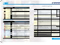
COMMON SPECIFICATIONS
Item
Carrier frequency *2)
Accuracy (Stability)
Setting resolution
Explanation
50 to 400Hz *1)
25 to 400Hz *1)
0.2 to 60Hz, Holding time: 0.0 to 10.0s
0.75 to 15kHz (55kW or smaller)*3) - 0.75 to 6kHz (90kW or larger)
Analog setting : ±0.2% of maximum frequency (at 25 ± 10°C)
Digital setting : ±0.01% of Maximum frequency (at -10 to +50°C)
Analog setting: 1/3000 of maximum frequency ex.) 0.02Hz at 60Hz, 0.04Hz at 120Hz, (0.15Hz at 400Hz : EN)
Digital setting: 0.01Hz at maximum frequency of up to 99.99Hz (0.1Hz at maximum frequency of 100Hz and above)
LINK setting: 1/20000 of maximum freq. ex.) 0.003Hz at 60Hz, 0.006Hz at 120Hz, (0.02Hz at 400Hz : EN) 0.01Hz (Fixed)
V/f control (Sinusoidal PWM control) · Dynamic torque-vector control (Sinusoidal PWM control)
Vector control with PG (*)
Voltage/freq. (V/f) characteristic Adjustable at base and maximum frequency, with AVR control : 320 to 480V
Torque boost
Selectable by load characteristics: Constant torque load (Auto/manual), Variable torque load (Manual)
KEYPAD operation:
or
key,
key
Control method
Operation method
Frequency setting
(Frequency command)
PID control
Control
Output
frequency
Maximum frequency
Base frequency
Starting frequency
Item
Automatic deceleration
Second motor’s setting
Energy saving operation
Fan stop operation
Universal DI
Universal DO
Universal AO
Zero speed control (*)
Positioning control (*)
Synchronized operation (*)
Digital input signal operation : FWD or REV command, Coast-to-stop command, etc.
LINK operation: RS485 (Standard) / T-Link (FUJI private link), Profibus-DP, Interbus-S, DeviceNet,
Modbus Plus, JPCN1, CAN open (Option) and any open bus.
KEYPAD operation:
or
key
External potentiometer (*) : 1 to 5kΩ (1/2W)
Analog input
: 0 to +10V DC (0 to +5V DC), 4 to 20mA DC
Reversible
: 0 to ±10V DC (0 to ± 5V DC) ....Reversible operation by polarized signal can be selected.
Inverse
: +10 to 0V DC, 20 to 4mA DC......Inverse mode operation can be selected.
UP/DOWN control : Output frequ. increases when UP signal is ON, and decreases when DOWN signal is ON.
Multistep frequency: Up to 16 different frequencies can be selected by digital input signal.
Pulse train input (*): 0 to 100kp/s
Running status signal
Acceleration / Deceleration
time
Active drive
Frequency limiter
Bias frequency
Gain for frequency setting
Jump frequency control
Rotating motor pick up
(Flying start)
Analog output (1 point)
: Output frequency, Output current, Output torque, etc.
Pulse output (1 point) : Output frequency, Output current, Output torque, etc.
0.01 to 3600s
: · independently adjustable acceleration and deceleration · 4 different times are selectable.
Mode select
: linear, S-curve (weak), S-curve (strong), Non-linear
When the acceleration time reaches 60s, the motor output torque is automatically reduced to rated torque.
Then the motor operation mode is changed to torque limiting operation.
The acceleration time is automatically extended up to 3 times.
High and Low limiter can be preset.
Bias frequency can be preset.
Gain for freq. setting can be preset. (0.0 to 200.0%) ex.) Analog input 0 to +5V DC with 200% gain results in max. frequ. at 5V DC.
Jump frequency (3 points) and its common jump hysteresis width (0 to 30Hz) can be preset.
A rotating motor (including inverse rotating mode) can be smoothly picked up without stopping the motor
(speed search method).
Auto-restart after momentary Automatic restart is available without stopping motor after a momentary power failure (speed search method). When "Smooth
recovery" mode is selected, the motor speed drop is held min. (The inverter searches the motor speed, and smoothly returns to
power failure
setting frequency. Even if the motor circuit is temporarily opened, the inverter operates without a hitch ).
Line / Inverter changeover
operation.
Controls the switching operation between line power and inverter. The inverter has sequence function inside.
Slip compensation
The inverter output frequ. is controlled according to the load torque to keep motor speed constant. When the value is set at "0.00" and "Torque-vector" is set at "active", the compensation value automatically selects the 4-pole
standard motor. Slip compensation can be preset for the second motor.
Droop operation
Torque limiting
Torque control
8
Operation mode (Running)
The motor speed droops in proportional to output torque (–9.9 to 0.0Hz).
When the motor torque reaches a preset limiting level, this function automatically adjusts the output frequency to
prevent the inverter from tripping due to an overcurrent.
Torque limiting 1 and 2 can be individually set, and are selectable with a digital input signal.
Output torque (or load factor) can be controlled with an analog input signal
Indication
Control
Jogging operation
Digital signal (parallel ) (*) : 16-bit binary
LINK operation : RS485 (Standard) / T-Link (FUJI private link), Profibus-DP, Interbus-S,
DeviceNet, Modbus Plus, JPCN1, CAN open (Option) and any open bus
Programmed PATTERN operation: Max. 7 stages
or
key, FWD or REV digital input signal
Transistor output (4 points) : RUN, FAR, FDT, OL, LU, TL, etc.
Relay output (2 points) : · Same as transistor output · Alarm output (for any fault)
Stopping
Trip mode
Explanation
This function can control flowrate, pressure, etc. (with an analog feedback signal.)
• Reference · KEYPAD operat. (
or
key) : Setting freq. / Max. freq. X 100 (%) · PATTERN operation : Setting
signal · Voltage input (Terminal 12 and V2 )
: 0 to +10V DC
freq./Max. freq. X 100 (%)
· Current input (Terminal C1 )
: 4 to 20mA DC
· DI option input (*) : · BCD,
· Reversible operation with polarity (Terminal 12)
: 0 to ±10V DC
setting freq./Max.freq. X 100 (%)
· Reversible operation with polar. (Terminal 12 + V1 ) : 0 to ±10V DC
· Binary, full scale/100 (%)
· Inverse mode operation (Terminal 12 and V2 )
: +10 to 0V DC
· Multistep frequ. setting :
· Inverse mode operation (Terminal C1)
: 20 to 4mA DC
Setting freq./Max.
RS485 : Setting freq./Max.
freq. X 100 (%) ·freq. X 100 (%)
• Feedback signal · Terminal 12 (0 to +10V DC or +10 to 0V DC)
· Terminal C1 (4 to 20mA DC or 20 to 4mA DC)
Torque limiter 1 (Braking) is set at "F41: 0" (Same as Torque limiter 2 (Braking) ).
· In deceleration: the deceleration time is automatically extended up to 3 times the setting time for tripless
operation even if braking resistor not used.
· In constant speed operation: Based on regenerative energy, the frequ. is increased and tripless operation is active.
This function is used for two motors switching operation.
· The second motor’s V/f characteristics (base and maximum frequency) can be preset.
· The second motor’s circuit parameter can be preset. Torque-vector control can be applied to both motors.
This function minimizes inverter and motor losses at light load.
This function is used for silent operation or extending the fan's lifetime.
Transmits to main controller of LINK operation.
Outputs command signal from main controller of LINK operation.
Outputs analog signal from main controller of LINK operation.
The motor speed is controlled with the speed reference of zero.
The SY option card can be used for positioning control by differential counter method.
This function controls the synchronized operation between 2 axes with PGs.
LCD monitor
LED monitor
(English, German, French, Spanish, Italian, Japanese)
·
·
·
·
·
·
·
·
·
·
·
·
·
Output frequency 1 (Before slip compensation) (Hz)
Output frequency 2 (After slip compensation) (Hz)
Setting frequency (Hz)
Output current (A)
Output voltage (V)
Motor synchronous speed (r/min)
Line speed (m/min)
Load shaft speed (r/min)
Torque calculation value (%)
Input power (kW)
PID reference value ("F01")
PID reference value (Remote) ("C30")
PID feedback value
Operation monitor & Alarm monitor
Operation monitor
· Displays operation guidance
· Bargraph: Output frequency (%), Output current (A),
Output torque (%)
Alarm monitor
· The alarm data is displayed when the inverter trips.
Function setting & monitor
Function setting
Displays function codes and its data or data code, and
changes the data value.
· Trip history :Cause of trip by code (Even when main Operation condition
· Motor synchronous speed
· Output frequency (Hz)
power supply is off, trip history data of the last 4 trips
(r/min)
are retained.)
· Output current (A)
· Load shaft speed (r/min)
Selected setting value or output value
· Output voltage (V)
· Line speed (m/min)
· Torque calculation value (%)· PID reference value
Displays the cause of trip by codes as follows.
· Setting frequency (Hz) · PID feedback value
· OC1 (Overcurrent during acceleration)
· Operation condition
· Driving torque limiter
. OC2 (Overcurrent during deceleration)
setting vaiue (%)
· OC3 (Overcurrent running at constant speed)
(FWD / REV, IL, VL / LU, TL)· Braking togue limiter
· EF (Ground fault)
setting value (%)
· Lin (Input phase loss)
Tester function
· FUS (Fuse blown)
(I/O check)
· OU1 (Overvoltage during acceleration)
· Digital I/O:
(ON),
(OFF)
· OU2 (Overvoltage during deceleration)
· Analog I/O: (V), (mA), (H), (p/s)
· OU3 (Overvoltage running at constant speed)
Maintenance data
· LU (Undervoltage)
· Operation time (h)
· Cooling fan operation time (h)
· OH1 (Overheating at heat sink)
· Communication error times
· DC link circuit voltage (V)
· OH2 (External thermal relay tripped)
· Temperature at inside air / (KEYPAD, RS485, Option)
· OH3 (Overtemperature at inside air)
· ROM version
heat sink (°C)
· Maximum current (A)
(Inverter, KEYPAD, Option)
· Main circuit capacitor life(%)
· Control PC board life (h)
GVX2000
9
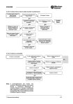
TERMINAL FUNCTIONS
Common Specifications (continued)
Explanation
Charge lamp
Overload
Overvoltage
Undervoltage
Input phase loss
Overheating
Short-circuit
Protection
Ground fault
Alarm data
· Output frequency (Hz) · Temperature at inside air (°C)
· Output current (A)
· Hest sink temperature (°C)
· Output voltage (V)
· Communication error times
· Torque calculation value (%) (KEYPAD, RS485 Option)
· Setting frequency (Hz) · Digital input terminal condition
· Operation condition
(Remote, Communication)
(FWD / REV, IL, VL / LU, TL) ·Transistor output terminal
condition
· Operation time (h)
· Trip history code
· DC link circuit voltage (V) · Multiple alram exist
When the DC link circuit voltage is higher than 50V, the charge lamp is ON.
Protects the inverter by electronic thermal and detection of inverter temperature.
Detects DC link circuit overvoltage, and stops the inverter. 400V series: 800V DC
Detects DC link circuit undervoltage, and stops the inverter. 400V series: 400V DC
Phase loss protection for power line input.
Protects the inverter by detection of inverter temperature.
Short-circuit protection for inverter output circuit
· Ground fault protection for inverter output circuit (3-phase current detection method)
· Zero-phase current detection method (30kW or larger)
Motor overload
DB resistor overheating
· Prevents DB resistor overheating by internal electronic thermal overload relay (11kW or smaller).
· Prevents DB resistor overheating by external thermal overload relay attached to DB resistor (15kW or larger).
(The inverter stops electricity discharge operation to protect the DB resistor.)
Output phase loss
Motor protection by PTC
thermistor
Auto reset
Installation location
Altitude
Ambient temperature
Ambient humidity
Vibration
Storage condition
Symbol
Load factor calculation
· Measurement time (s) · Average current (A)
· Maximum current (A) · Average braking power (%)
· The inverter trips, and then protects the motor.
· Electronic thermal overload relay can be selected for standard motor or inverter motor
· Thermal time constant (0.5 to 75.0 minutes) can be preset for a special motor.
· The second motor's electronic thermal overload relay can be preset for 2-motor changeover operation.
Stall prevention
Condition (installation
and operation)
dBH (Overheating at DB circuit)
OL1 (Motor 1 overload)
OL2 (Motor 2 overload)
OLU (Inverter unit overload)
OS (Overspeed)
PG (PG error)
Er1 (Memory error)
Er2 (KEYPAD panel communication error)
Er3 (CPU error)
Er4 (Option error)
Er5 (Option error)
Er7 (Output phase loss error, impedance
imbalance)
· Er8 (RS485 error)
NOTES: (*) Option
*1) For application at 120Hz or above, please contact Silectron Sistemi
*2) Inverter may automatically reduce carrier frequency, in accordance with ambient temperature or output current for protecting inverter.
*3) The minimum carrier frequency changes depending on maximum output frequency.
P(+), N(-)
For braking unit
R0, T0
13
For external
braking resistor
Grounding
Auxiliary control
power supply
Potentiometer
power supply
Voltage input
12
(Torque control)
(PID control)
(PG feedback)
Current input
C1
(PID control)
(PTC-Thermistor Input)
V2
11
FWD
REV
When the inverter is tripped, it resets automatically and restarts.
-Temperature : –25 to +65 °C, -Humidity : 5 to 95%RH (non-condensing)
For DC reactor
G
When the motor temperature exceeds allowable value, the inverter trips automatically.
5 to 95%RH (non-condensing)
3mm at from 2 to less than 9Hz, 9.8m/s2 at from 9 to less than 20Hz
2m/s2 at from 20 to less than 55Hz, 1m/s2 at from 55 to less than 200Hz
P1, P(+)
P(+), DB
· Controls the output frequency to prevent
(overcurrent) trip when the output current exceeds the limit value
during acceleration.
· Lowers the output frequency to hold almost constant torque when the output current exceeds the limit value
during operation at constant speed.
· Controls the output frequency to prevent
(overvoltage) trip when the DC link circuit voltage exceeds the
limit value during deceleration.
When the inverter executes auto-tuning, detects each phase impedance imbalance (and stops the inverter).
Free from corrosive gases, flammable gases, oil mist, dusts, and direct sunlight.
Indoor use only.
1000m or less. Applicable to 3000m with power derating (-10%/1000m)
–10 to +50 °C. For inverters of 22kW or smaller, remove the ventilation covers when operating it at a temperature of 40 °C or above.
Terminal name
L1/R, L2/S
Power input
L3/T
U, V, W
Inverter output
Main
circuit
Trip mode
·
·
·
·
·
·
·
·
·
·
·
·
Digital
input
Indication
LED monitor
Terminal Functions
LCD monitor
(English, German, French,Spanish, Italian, Japanese)
Analog
input
Item
X1
X2
X3
X4
X5
X6
X7
X8
X9
Voltage input 2
Common
Forward operation
command
Reverse operation
command
Digital input 1
Digital input 2
Digital input 3
Digital input 4
Digital input 5
Digital input 6
Digital input 7
Digital input 8
Digital input 9
Function
Remarks
Fun.
cod.
Connect a 3-phase power supply.
Connect a 3-phase induction motor.
Connect the DC reactor for power-factor correcting
or harmonic current reducing.
· Connect the braking unit (option).
· Used for DC bus connection system.
Connect the external braking resistor (option)
DC reactor: option
Braking unit (option): 11kW or larger
Only for 11kW or smaller
Ground terminal for inverter chassis (housing).
Connect the same AC power supply as that of the main
circuit to back up the control circuit power supply.
+10V DC power supply for frequency setting POT
(POT: 1 to 5kΩ)
· 0 to +10V DC/0 to 100% (0 to +5V DC/0 to 100%)
· Reversible operation can be selected by function setting.
0 to ±10V DC /0 to ±100% (0 to ±5V DC/0 to ±100%)
· Inverse mode operation can be selected by function
setting or digital input signal.
+10 to 0V DC/0 to 100%
Used for torque control reference signal.
Used for PID control reference signal or feedback signal.
Used for reference signal of PG feedback control (option)
· 4 to 20mA DC/0 to 100%
· Inverse mode operation can be selected by function
setting or digital input signal.
20 to 4mA DC/0 to 100%
Used for PID control reference signal or feedback signal.
The PTC-thermistor (for motor protection) can be
connected to terminal C1 - 11.
0 to +10V DC
Common for analog signal
FWD: ON ..... The motor runs in the forward direction.
FWD: OFF ..... The motor decelerates and stops.
REV: ON ..... The motor runs in the reverse direction.
REV: OFF ..... The motor decelerates and stops.
1,1kW or smaller: Not correspond
Allowable maximum output current : 10mA
· Input impedance: 22kΩ
· Allowable maximum input voltage: ±15V DC
F01,C30
· If input voltage is 10 to 15V DC, the
inverter estimate it to10V DC.
H18
F01, H21
· Input impedance:250kΩ
· Allowable maximum input current: 30mA DC
· If input current is 20 to 30mA DC , the
inverter estimates it to20mA DC.
Change over the Pin switch on control
board. (SW2 : PTC)
Can't change over the terminal C1.
Isolated from terminal CMY and CM.
F01, H21
H26,
H27
F01
When FWD and REV are simultaneously
F02
ON, the motor decelerates and stops.
These terminals can be preset as follows.
· OFF state maximum input voltage: 2V
(maximum source current : 5mA) E01 to
· ON state maximum terminal
E09
voltage: 22 to 27V
(allowable maximum leakage
current: 0.5mA).
(SS1)
(SS2) Multistep freq.
(SS4) selection
(SS8)
(SS1)
: 2 (0, 1) different freq. are selectable.
(SS1,SS2)
: 4 (0 to 3) different freq. are selectable.
(SS1,SS2,SS4) : 8 (0 to 7) different freq. are selectable.
(SS1,SS2,SS4,SS8) :16 (0 to 15) different freq. are selectable.
Frequency 0 is set by F01 (or C30).
(All signals of SS1 to SS8 are OFF)
C05 to
C19
(RT1) ACC / DEC time
(RT2) selection
: 2 (0, 1) different ACC / DEC times are selectable. Time 0 is set by F07/F08.
(RT1)
(RT1,RT2) : 4 (0 to 3) different ACC / DEC times are selectable (All signals of RT1 to RT2 are OFF)
F07, F08
E10 to
E15
(HLD)
3-wire operation
stop command
Used for 3-wire operation.
(HLD): ON ..... The inverter self-holds FWD or REV signal.
(HLD): OFF ..... The inverter releases self-holding.
Assigned to terminal X7 at factory setting.
GVX2000
10
11
Terminal Functions (continued)
(RST) Alarm reset
(THR)
Trip command
(External fault)
(JOG) Jogging operation
(Hz2/Hz1)
Freq. set 2 / 1
(THR): OFF ..... "OH2 trip" occurs and motor will coast-to-stop.
This alarm signal is held internally.
(JOG): ON ..... JOG frequency is effective.
(Hz2/Hz1): ON ..... Freq. set 2 is effective.
This signal is effective only while the
inverter is stopping.
If this signal is changed while the inverter is running, the signal is effective
only after the inverter stops.
(DCBRK) DC brake command
(DCBRK): ON ..... The DC injection brake is effective.
(In the inverter deceleration mode)
If the operation command(FWD/REV) is
input while DC braking is effective, the
operation command (FWD/REV) has
priority.
(TL2/TL1) Torque limiter 2 /1
(TL2/TL1): ON ..... Torque limiter 2 is effective.
Switching operation
between line and inverter
(SW60)
(UP) UP command
Digital input
· The motor restarts from 0Hz by turning
off BX with the command operation
H11
· Assigned to terminal X8 at factory setting.
· During normal operating, this signal is ignored.
· Assigned to X9 at factory setting.
If this signal is changed while the inverter
is running, the signal is effective only after
the inverter stops.
(SW50)
(DOWN) (DOWN) command
Fun.
cod.
(BX): ON ..... Motor will coast-to-stop.
(No alarm signal will be output.)
command (FWD or REV) ON.
(RST): ON ..... Faults are reset. (This signal should be
held for more than 0.1s.)
(M2/M1): ON ..... The motor circuit parameter and V/f
characteristics are changed to the second motor's ones.
(M2/M1) Motor 2 / Motor 1
(SW50(SW60)): ON .....The motor is changed from inverter
operation to line operation.
(SW50(SW60)): OFF ..... The motor is changed
from line operation to inverter operation.
(UP): ON ..... The output frequency increases.
(DOWN): ON ..... The output frequency decreases.
· The output frequency change rate is determined
by ACC / DEC time.
· Restarting frequency can be selected from 0Hz or
setting value at the time of stop.
C20
C30 /
F01
A10 to
A18 /
P01 to
P09
F20 to
F22
E16,E17
F40,F41
When UP and DOWN commands are
simultaneously ON, DOWN signal is
effective.
(RUN)
(FAR)
(FDT1)
F00
(Hz/PID) PID control cancel
(Hz/PID): ON ..... The PID control is canceled, and
frequency setting by KEYPAD (
or
) is effective.
H20 to
H25
F01,C30
Inverse mode
changeover
(IL) Interlock sig. for 52-2
(Hz/TRQ) TRQ control cancel
(LE)
Link enable
(RS485, Bus)
(U-DI) Universal DI
(STM) Pick up start mode
(PG/Hz) SY-PG enabled
(SYC)
Synchronization
command
(ZERO) Zero speed command
(STOP1) Forced stop command
Forced stop command
(STOP2)
Deceleration time4.
(EXITE) Pre-exciting command
PLC
PLC terminal
P24
DC voltage supply
(IVS): ON ..... Inverse mode is effective in analog signal input.
Connect to auxiliary contact (1NC) of 52-2.
(Hz/TRQ): ON ..... The torque control is canceled,
and ordinary operation is effective.
(LE): ON ..... The link opereation is effective. Used to
switch operation between ordinary operation and link
operation to communication.
This signal is transmitted to main controller of LINK operation.
(STM): ON ..... The "Pick up" start mode is effective.
(PG/Hz): ON ..... Synchronized operation or PG-feedback
operation is effective.
(SYC): ON ..... The motor is controlled for synchronized
operation between 2 axes with PGs.
(ZERO): ON ..... The motor speed is controlled with the
speed reference of zero.
(STOP1): OFF ..... The motor decelerates and stops.
(STOP2): OFF ..... The motor decelerates and stops with
with Deceleration time 4
(EXITE): ON ..... The magnetic flux can be established
preliminary before starting at PG vector mode.
Connect PLC power supply to avoid malfunction of the
inveter that has SINK type digital input, when PLC
power supply is off.
DC voltage supply (+24V, max. 100mA)
(CM)
F01,C30
(WE-KP): ON ..... The data is changed by KEYPAD.
If this signal is changed while the inverter
is running, the signal is effective only
after the inverter stops.
H18
RS485: Standard, Bus: Option
H30
H09
Option
(LU)
(B/D)
(TL)
(IPF)
(OL1)
(KP)
(STP)
(RDY)
Option
(SW88)
This function can be selected at PG
feedback control. Option
(SW52-2)
E15
Terminal name
Function
Output voltage (0 to 10V DC) is proportional to selected
function’s value as follows.
The proportional coefficient and bias value can be preset.
· Output frequency 1
(Before slip compensation)
(0 to max. frequency)
· Output frequency 2
(After slip compensation)
(0 to max. frequency)
FMA
Analog monitor
· Output current
(0 to 200%)
· Output voltage
(0 to 200%)
· Output torque
(0 to 200%)
· Load factor
(0 to 200%)
· Input power
(0 to 200%)
· PID feedback value
(0 to 100%)
· PG feedback value
(0 to max. speed)
· DC link circuit voltage
(0 to 1000V)
(11) (Common)
· Universal AO
(0 to 100%)
Pulse rate monitor · Pulse rate mode : Pulse rate is proportional to selected
FMP
function’s value* (50% duty pulse)
· Average voltage mode : Average voltage is proportional to
selected function’s value* (2670p/s pulse width control)
CM
Y1
Y2
Y3
Y4
Main circuit changeover signals are output
through Y1 to Y5 terminal.
Write enable for
(WE-KP)
KEYPAD
(IVS)
12
Remarks
Analog output
(BX) Coast-to-stop
Function
Pulse output
Terminal name
Transistor output
Symbol
Symbol
(SW52-1)
(SWM2)
(Common)
Remarks
Fun.
cod.
Allowable maximum output current: 2mA F30 to
F31
Allowable maximum output current : 2mA
F33 to
F35
· Kinds of function to be output is same as those of analog
output (FMA).
Common for pulse output
Isolated from terminal CMY and 11.
Common
· OFF state maximum output voltage : 3V
Transistor output 1
(Allowable maximum sink current : 50mA)
Transistor output 2
Output the selected signals from the following items.
· ON state maximum leakage current : 0.1mA
Transistor output 3
(Allowable maximum voltage : 27V)
Transistor output 4
Outputs ON signal when the output frequency is higher than
Inverter running
starting frequency.
Frequency equi- Outputs ON signal when the difference between output frequency
and setting frequency is smaller than FAR hysteresis width.
valence signal
Outputs ON signal by comparison of output frequency and
Frequency level
preset value (level and hysteresis).
detection
Outputs ON signal when the inverter stops by undervoltage
Undervoltage
while the operation command is ON.
detection signal
Outputs ON signal in braking or stopping mode, and OFF
Torque polarity
signal in driving mode.
Outputs ON signal when the inverter is in torque-limiting
Torque limiting
mode.
Outputs ON signal during auto restart operation (Instantaneous
Auto-restarting
power failure) mode. (including "restart time")
· Outputs ON signal when the electronic thermal value is
higher than preset alarm level.
Overload early
· Outputs ON signal when the output current value is higher
warning
than preset alarm level.
Outputs ON signal when the inverter is in KEYPAD operation
KEYPAD
mode.
operation mode
Outputs ON signal when the inverter is in stopping mode or in
Inverter stopping
DC braking mode.
Ready output
Outputs ON signal when the inverter is ready for operation.
Line/Inverter
Outputs 88's ON signal for Line/Inverter changeover operation.
changeover for 88)
Line/Inv changeover
Outputs 52-2’s ON signal for Line/Inverter changeover operation.
(for 52-1)
Line/Inv changeover
Outputs 52-1’s ON signal for Line/Inverter changeover operation.
(for 52-1)
Outputs the motor changeover switch ON signal from motor 1
Motor2/Motor1
to motor 2.
E20 to
E23
E30
E31,
E32
E33 to
E35
F02
A01 to
A18
GVX2000
13
BASIC WIRING DIAGRAM
Terminal Functions (continued)
Symbol
(AX)
Terminal name
Auxiliary terminal
(for 52-1)
(TU) Time-up signal
(TO)
(STG1)
(STG2)
Transistor output
(STG4)
(AL1)
(AL2)
(AL4)
(AL8)
(FAN)
Cycle completion
signal
Stage No.
indication 1
Stage No.
indication 2
Stage No.
indication 4
Alarm indication 1
Alarm indication 2
Alarm indication 4
Alarm indication 8
Fan operation signal
(TRY) Auto-resetting
(U-DO) Universal DO
Overheat early
(OH)
warning
Synchronization
(SY)
completion signal
(LIFE)
(FDT2)
(OL2)
(C1OFF)
(N-EX)
LINK
Relay output
CMY
30A,
30B,
30C,
Y5A, Y5C
Function
Used for auxiliary circuit of 52-1.
(Same function as AX1, AX2 terminal by FRENIC5000G9S
series. (30kW or larger))
Outputs time up signal (100ms ON pulse) at every stage end
of PATTERN operation.
Outputs one cycle completion signal (100ms ON pulse) at
PATTERN operation.
Remarks
Fun.
cod.
Keypad panel Operation
The following diagram is for reference only. For detailed wiring diagrams, refer to the relevant instruction manual.
Refer to wiring diagram example.
11 kW or smaller
Main circuit
C21 to
C28
(*3)
P1
P1
N(-)
L1/R
Power supply
(*1) 3-phase
380 to 480V
50/60Hz
Outputs PATTERN operation’s stage No. by signals STG1,
STG2 and STG4.
P(+)
P1
MCCB or ELCB ( *2)
(*3)
DC reactor
(DCR)
(*6)
Jumper wire
L3/T
V
M
W
Motor*
G
(R0)
(T0)
Outputs trip alarm No. by signals AL1, AL2, AL4, and AL8.
Voltage
input
Analog input
Voltage input 2
DX+, DX-, RS485 I/O terminal
Connect the RS485 link signal.
SD
+DC10V
13
Potentiometer power supply
0V
12
30A
Alarm output (for any
fault)
30C
C1
FMA
+DC 0~10V
+DC24V 0V
P24
PLC
(*6)
Source
FWD
Sink
REV
CM
Y5C
X1
X2
X3
Digital input
30B
30
11
V2
Current input
Synchronization completion signal for synchronized operation. Option
Outputs ON signal when the calculated lifetime is longer than
Lifetime alarm
preset alarm level.
2nd-outputs ON signal by comparison of output frequency and
2nd Freq. level
preset value (FDT2 level).
detection
2nd OL level early 2nd-outputs ON signal when the output current value is larger
warning
than preset alarm level (OL2 level).
Terminal C1 off
Outputs ON signal when the C1 current is smaller than 2mA.
signal
Speed existence Outputs ON signal when motor speed is larger than stop
* stop speed = stop frequency (F25)
signal
speed* on vector control with PG.
120/pole [r/m]
Common
Common for transistor output signal.
Isolated from teminals CM and 11.
(transistor output)
Outputs a contact signal when a protective function is
activated.
Alarm relay output
Changeable exciting mode active or non-exciting mode active · Contact rating :
by function "F36".
250V AC, 0.3A, cosΦ=0.3
Funcntions can be selected the same as Y1 to Y4.
48V DC, 0.5A, non-inductive
Relay output
Changeable exciting mode active or non-exciting mode active
by function "E25".
Grounding
Control circuit
H06
H04,
H05
Y5A
Relay
output
Y4
X4
Y3
X5
X6
Y2
X7
Y1
X8
Transistor
output
*1) Use the inverter whose rated input
voltage matches the power supply
voltage.
*2)Use this peripheral device when necessary.
*3)75kW or smaller:
Terminals [P1] and [P(+)] are connected
with a jumper wire before shipping. When
connecting an optional DC reactor (DCR)*6),
remove the jumper wire that connects the
terminals [P1] and [P(+)].
*4)For models from 0.55 to 11kW, a built-in
braking resistor (DBR) is connected to the
inverter before shipping. (DBR is not mounted
on models 15kW or larger.)
*5)Terminals [R0] and [T0] are provided for
models 2,2kW or larger. These terminals are
not provided for models 1,1kW or smaller.
Even if these terminals are not powered, the
inverter can be operated.
*6)Digital input common switching:
Source (P24 terminal)
Sink (CM terminal).
CMY
X9
F25
NOTE:
Common terminals [11], (CM),
and <CMY> for control circuits
are
G
G
Grounding
Outputs the inverter cooling fan operation status signal.
Outputs ON signal at auto resetting mode. (Including "Reset
interval")
Outputs command signal from main controller of LINK
operation.
Outputs ON signal when the heat sink temperature is higher
than (trip level – 10°C), and outputs OFF signal when the
temperature is lower than (trip level – 15°C).
DB N(-)
DBR (*4)
U
CNUX ( )
U1
U2
L2/S
Auxiliary control power supply( *5)
P(+)
P(+) N(-)
CM
Pulse output
(frequency monitor)
F36
E24
*Option
FMP
Pulse output
(DX-)
(DX+)
(SD)
RS485 interface port
Terminal Arrangement
E25
• Main circuit terminals
• Control circuit
terminals
30C
30A
30B
Y5A
Y5C
CMY
Y4
Y3
Y2
Y1
11
L1/R L2/S L3/T
C1
12
FMA
13
G
FMP
V2
PLC
DB
P1
P(+) N(-)
U
V
W
(Up to 11kW)
G
CM
X1
CM
X2
FWD
X3
REV
X4
P24
X5
P24
X6
DXB
X7
DXA
X8
SD
X9
14
GVX2000
15
KEYPAD PANEL FUNCTIONS AND OPERATIONS
External signal input Operation
The following diagram is for reference only. For detailed wiring diagrams, refer to the relevant instruction manual.
Keypad panel
11 kW or smaller
15 kW or larger
External braking resistor (DB) (*2) (*6)
External braking resistor (DB) (*2) (*6)
(THR)
P
DB
P
P
DB
N
Braking unit ( *2) ( *8)
P24
G
DC reactor (DCR)
(*2) ( *9)
G
Main circuit
Power supply ( *1)
3-phase
400 to 480V
50/60Hz
P(+)
P(+)
P1
DB
N(-)
DBR (*5)
N(-)
L1/R
Auxiliary control power supply ( *7)
(THR)
P24
DB
xx
(*4)
MCCB or ELCB ( *3)
P
G
U
L2/S
V
M
L3/T
W
Motor*
G
(R0)
G
G
Grounding
Grounding
Control circuit
3
13
Voltage
input
2
12
1
11
V2
Analog input
Voltage input 2
Current input
(+)
( 0V )
(+)
(-)
+DC10V
0V
30A
30
30B
Alarm output (for any fault)
RUN
30C
C1
FMA
+DC0~10V
+DC24V 0V
Program key
Switches the display to a
menu screen or to the initial
screen for operation mode or
alarm mode.
(*8)
Source
P24
PLC
Sink
FWD
REV
Digital input
CM
Y5C
X1
X2
X3
Y5A
X4
Y3
Y2
X6
Pulse output
(frequency monitor)
X7
Y1
X8
CMY
NOTE:
Common terminals [11], (CM), and <CMY>
for control circuits are isolated from one
another.
Transistor
output
X9
CM
60Hz
FMP
Pulse output
(DX-)
(DX+)
FWD/REV keys
In operation mode :
Starts the inverter with forward or
reverse operation command.
Pressing the FWD or REV key lights
the RUN lamp.
Invalid when the function code F02
(Operation method) is set at 1
(External signal
operation).
Relay output
Y4
X5
Unit indication
Displays the unit for the
information shown on the
LED monitor.
Up/Down keys
In operation mode :
Increases or decreases the
frequency or speed.
In program mode :
Increases or decreases
function code number and
data set value.
(T0)
Potentiometer power supply
LCD monitor
In operation mode :
Displays various items of information
such as operation condition and
function data. Operation guidance,
which can be scrolled, is displayed at
the bottom.
In program mode :
Displays functions and data.
LED monitor
In operation mode:
Displays the setting frequency,
output current, voltage, motor
speed, or line speed.
In trip mode:
Displays code indicating the
cause of trip.
(SD)
Shift key (Column shift)
In program mode :
Moves the cursor horizontally
at data change. Pressing this
key with the UP or DOWN
key, the screen changes to
the next function block.
GVX2000
Stop key
In operation mode :
Stops the inverter.
Invalid when the function code
F02 (Operation method) is set
at 1 (External signal
operation).
RS485 interface port
*Option
*1) Use the inverter whose rated input voltage matches the power
supply voltage.
*2) An optional device. Use it when necessary.
*3) Use this peripheral device when necessary.
*4) Terminals [P1] and [P(+)] are connected with a jumper wire
before shipping. When connecting an optional DC reactor (DCR)
*9), remove the jumper wire that connects the terminals [P1] and
[P(+)].
*5) For models from 0.2 to 11kW, a built-in braking resistor (DBR) is
connected to the inverter before shipping. (DBR is not mounted on
models 15kW or larger.) When connecting an optional external
braking resistor (DB), remove the DBR connection cables from
[P(+)] and [DB] terminals. The end of the removed cables (indicated
with an X) must be insulated.
16
*6) When connecting an optional external braking resistor (DB), be
sure to also use an optional braking unit *8). Connect the optional
braking unit to the [P(+)] and [N(-)] terminals. Auxiliary terminals
[1] and [2] have polarity.
Be sure to connect cables to these terminals correctly. (See the
diagram)
*7) Terminals [R0] and [T0] are provided for models 2.2kW or larger.
These terminals are not provided for models 1.1kW or smaller.
Even if these terminals are not powered, the inverter can be
operated.
*8)Digital input common switching:
Source (P24 terminal)
Sink (CM terminal).
Reset key
In program mode :
Cancels the current input
data and shifts the screen.
In trip mode :
Releases the trip-stop state.
Function/Data Select key
In operation mode :
Changes the displayed values
of LED monitor.
In program mode :
Selects the function code or store the
data.
GVX2000
17
FUNCTION SETTINGS
Keypad panel operation
Perform the wiring shown in the Basic wiring diagram on page 14. Turn on inverter power, and use the
set an output frequency. Press the
key, then press the
FWD
or
REV
or
key to
Fundamental Functions
key.
The inverter starts running using the factory setting function data.
Press the
The functions in the yellow boxes can be set while the inverter is running. Other functions must be set while the inverter is stopped.
Factory setting
Min.
Setting range
unit
Name
LCD monitor
-25kW
30kWFunction
Code
key to stop the inverter.
Procedure for selecting function codes and data codes
The following is a sample procedure for selecting a function code and changing the function data.
1
Press the
key to switch the operation monitor screen
RUN
FWD
→
PRG
PRG MENU
to the program menu screen.
Frequency command 1
F/D → LED SHIFT
2 Select “1. DATA SET” , and press the
→ 1. DATA SET
key.
2. DATA CHECK
3. OPR MNT
4. I / O CHECK
Operation method
or
key to select a target function
code. To quickly scroll the function select screen, press
SHIFT
»
key and the
4 Press the
Use the
or
key at the same time.
F00 DATA PRTC
F01 FREQ COM 1
F02 OPR METOD
F03 MAX Hz-1
key to show the actual function setting.
,
, and
SHIFT
»
keys to change the function
data to the target value. (Use the
SHIFT
»
key to move the cursor
F01 FREQ COM 1
0
0~11
key to store the updated function
F02 OPR METOD
F03 MAX Hz-1
F04 BASE Hz-1
F05 RATED V-1
data in memory.
The screen shifts for the selection of the next function.
6 Pressing the
F05 RATED V-1
0
-
0
-
0
1Hz
1Hz
50
50
0 (Free), 320 to 480V
1V
400
F06 MAX V-1
320 to 480V
1V
400
F07 ACC TIME1
F08 DEC TIME1
0.01 to 3600s
0.01s
0.01 to 3600s
0.01s
0.0 : Automatic
(for constant torque load)
0.1 to 1.9 : Manual
(for variable torque load)
0.1
2.0 to 20.0 :Manual
(for constant torque load)
0
: Inactive
1
: Active (for 4-pole standard motor)
2
: Active (for 4-pole inverter motor)
Approx. 20 to 135% of rated current
0.01A
0.5 to 75.0 min
0.1min
[11kW or smaller]
0
: Inactive
1
: Active (for built-in braking resistor)
2
: Active (for external braking resistor)
[15kW or larger]
0
: Inactive
0
: Inactive (Trip and alarm when power failure occurs.)
1
: Inactive (Trip, and alarm when power recovers.)
2
: Inactive (Deceleration stop, and alarm.)
3
: Active (Smooth recovery by continuous operation mode)
4
: Active (Momentarily stops and restarts at output
frequency of before power failure)
5
: Active (Momentarily stops and restarts at starting
frequency)
0 to 400Hz
1Hz
0 to 400Hz
1Hz
F09 TRQ BOOST1
(Select) F10 ELCTRN OL1
(Level) F11 OL LEVEL1
(Thermal time constant) F12 TIME CNST 1
F13 DBR OL
FWD
PRG → PRG MENU
F/D → LED SHIFT
Restart mode after
momentary power failure
1) Setting a frequency
When the operation monitor screen is displayed, a frequency can be set by using the
in both the operation and stop modes. When the target frequency is displayed, press the
or
key to
2) Switching a unit indication
key is pressed, the value displayed on the
LED monitor changes, and the unit indication on the LCD monitor shifts from Hz to A, V, r/min, m/min,
kW, and torque %, in this order in accordance with the displayed value.
F14 RESTART
key
enter the frequency in memory.
0
1
0
1
-
RUN
monitor screen.
18
Torque boost 1
Electronic thermal
overload relay
(for braking resistor)
key switches the screen to the operation
During both operation and stop modes, each time the
Maximum frequency 1
Base frequency 1
Rated voltage 1
( at Base frequency 1 )
Maximum voltage 1
( at Maximum frequency 1 )
Acceleration time 1
Deceleration time 1
Electronic
thermal overload
relay for motor 1
when you want to enter a numerical value.)
5 Press the
Basic Functions
3 Press the
: Data change enable
: Data protection
: KEYPAD operation (
or
key)
: Voltage input (terminals 12 and V2) (0 to +10V
DC, 0 to +5V DC)
2
: Current input (terminal C1) (4 to 20mA DC)
3
: Voltage and current input (terminals 12 and C1)
4
: Reversible operation with polarity (terminal 12)(0
to ±10V DC)
F01 FREQ CMD 1 5
: Reversible operation with polarity (terminals 12
and V1) (0 to ±10V DC)
6
: Inverse mode operation (terminals 12 and V2)
(+10 to 0V DC)
7
: Inverse mode operation (terminal C1) (20 to 4mA DC)
8
: UP/DOWN control 1 (initial freq. = 0Hz)
9
: UP/DOWN control 2 (initial freq. = last value)
10 : PATTERN operation
11
: DI option or Pulse train input
0
: KEYPAD operation ( FWD or REV or
key)
F02 OPR METHOD
1
: FWD or REV command signal operation
F03 MAX Hz-1
50 to 400Hz
F04 BASE Hz-1
25 to 400Hz
F00 DATA PRTC
Data protection
Frequency
(High) F15 H LIMITER
limiter
(Low) F16 L LIMITER
Gain (for frequency
F17 FREQ GAIN
setting signal)
0.0 to 200.0%
0.1%
6.00
6.00
20.00
20.00
0.0
(EV : 0.1)
1
*1)
5.0
10.0
1
0
0
70
0
100.0
GVX2000
19
Extension Terminal Functions
Fundamental functions (continued)
Name
LCD monitor
Bias frequency
DC brake (Starting freq.)
(Braking level)
(Braking time)
Starting frequency (Freq.)
(Holding time)
Stop frequency
F18
F20
F21
F22
F23
F24
F25
Motor sound (Carrier freq.) F26
(Sound tone) F27
FMA
(Voltage adjust) F30
Basic Functions
(Function) F31
(Pulse rate) F33
FMP
(Voltage adjust) F34
(Function) F35
30RY operation mode
Torque limiter 1
F36
(Driving) F40
(Braking) F41
F42
–400.0 to 400.0Hz
0.0 to 60.0Hz
0 to 100%
0.0 (DC brake inactive),
0.1 to 30.0s
0.1 to 60.0Hz
0.0 to 10.0s
0.1 to 6.0Hz
0.75 to 15kHz (Up to 75kW)
MTR SOUND
0.75 to 10kHz (90kW and above)
0
: level 0
1
: level 1
SOUND TONE
2
: level 2
3
: level 3
FMA V-ADJ
0 to 200%
0
: Output frequency 1 (Before slip compensation)
1
: Output frequency 2 (After slip compensation)
2
: Output current
3
: Output voltage
4
: Output torque
FMA FUNC
5
: Load factor
6
: Input power
7
: PID feedback value
8
: PG feedback value
9
: DC link circuit voltage
10 : Universal AO
FMP PULSES 300 to 6000 p/s (at full scale)
0%
: (Pluse rate output: 50% duty)
FMP V-ADJ
1 to 200% : (Voltage adjust: 2670p/s, duty adjust)
0
: Output frequency 1 (Before slip compensation)
1
: Output frequency 2 (After slip compensation)
2
: Output current
3
: Output voltage
4
: Output torque
FMP FUNC
5
: Load factor
6
: Input power
7
: PID feedback value
8
: PG feedback value
9
: DC link circuit voltage
10 : Universal AO
0
: The relay (30) excites on trip mode.
30RY MODE
1
: The relay (30) excites on normal mode.
DRV TRQ 1
20 to 200%, 999 (999: No limit) *2)
0 (Automatic deceleration control), 20 to 200%, 999
BRK TRQ 1
(999: No limit) *2)
0
: Inactive
TRQVECTOR1
1
: Active
Min.
unit
0.1Hz
0.1Hz
1%
0.1s
0.1Hz
0.1s
0.1Hz
1kHz
Code
0.0
0.0
0
0.0
0.5
0.0
0.2
15(Up to 75kW)*
10(90kW and above)*
-
0
1%
100
-
0
1p/s
1440
1%
Function
Name
X1 terminal function
X2 terminal function
X3 terminal function
X4 terminal function
X5 terminal function
X6 terminal function
X7 terminal function
X8 terminal function
X9 terminal function
E01
E02
E03
E04
E05
E06
E07
E08
E09
X1 FUNC
X2 FUNC
X3 FUNC
X4 FUNC
X5 FUNC
X6 FUNC
X7 FUNC
X8 FUNC
X9 FUNC
0
-
0
180
150
1%
150
100
0
1
2
3
4
5
6
7
8
9
10
11
12
13
14
15
17
18
19
20
21
22
23
24
25
26
27
28
29
30
31
32
0
Acceleration time 2
Deceleration time 2
Acceleration time 3
Deceleration time 3
Acceleration time 4
Deceleration time 4
Torque limiter 2 (Driving)
(Braking)
E10
E11
E12
E13
E14
E15
E16
E17
AAC TIME2
DEC TIME2
ACC TIME3
DEC TIME3
ACC TIME4
DEC TIME4
DRV TRQ 2
BRK TRQ 2
-
Selects from the following items.
16
1%
Min.
unit
Setting range
LCD monitor
0
-
-
The functions in the yellow boxes can be set while the inverter is running. Other functions must be set while the inverter is stopped.
Factory setting
-25kW
30kW-
ACC 2, 3, 4
DCE 2, 3, 4
Torque vector control 1
FREQ BIAS
DC BRK Hz
DC BRK LVL
DC BRK t
START Hz
HOLDING t
STOP Hz
Setting range
X1-X9 Terminal
Function
Code
Factory setting
-25kW
30kW0
1
2
3
4
5
6
7
8
:
[SS1]
:
[SS2]
: Multistep freq. selection (1 to 4 bit)
[SS4]
:
[SS8]
:
[RT1]
: ACC / DEC time selection (1 to 2 bit)
[RT2]
: 3-wire operation stop command
[HLD]
: Coast-to-stop command
[BX]
: Alarm reset
[RST]
: Trip command (External fault)
[THR]
: Jogging operation
[JOG]
: Freq. set. 2 / Freq. set. 1
[Hz2/Hz1]
: Motor 2 / Motor 1
[M2/M1]
: DC brake command
[DCBRK]
: Torque limiter 2 / Torque limiter 1
[TL2/TL1]
: Switching operation between line and inverter
50Hz)
[SW50]
: Switching operation between line and inverter
(60Hz)
[SW60]
: UP command
[UP]
: DOWN command
[DOWN]
: Write enable for KEYPAD
[WE-KP]
: PID control cancel
[Hz/PID]
: Inverse mode changeover (terminals 12 and C1)
[IVS]
: Interlock signal for 52-2
[IL]
: TRQ control cancel
[Hz/TRQ]
: Link enable (Bus,RS485)
[LE]
: Universal DI
[U-DI]
: Pick up start mode
[STM]
: SY-PG enable
[PG/Hz]
: Synchronization command
[SYC]
: Zero speed command
[ZERO]
: Forced stop command
[STOP1]
: Forced stop command with Deceleration time 4
[STOP2]
: Pre-exciting command
[EXITE]
0.01 to 3600s
20 to 200%, 999 (999: No limit) *2)
0 (Automatic deceleration control), 20 to 200%, 999
(999: No limit) *2)
0.01s
0.01s
0.01s
0.01s
0.01s
0.01s
1%
10.00
10.00
15.00
15.00
3.00
3.00
180
100.00
100.00
100.00
100.00
100.00
100.00
150
1%
180
100
GVX2000
20
21
Extension Terminal Functions
Fundamental functions (continued)
Name
LCD monitor
Bias frequency
DC brake (Starting freq.)
(Braking level)
(Braking time)
Starting frequency (Freq.)
(Holding time)
Stop frequency
F18
F20
F21
F22
F23
F24
F25
Motor sound (Carrier freq.) F26
(Sound tone) F27
FMA
(Voltage adjust) F30
Basic Functions
(Function) F31
(Pulse rate) F33
FMP
(Voltage adjust) F34
(Function) F35
30RY operation mode
Torque limiter 1
F36
(Driving) F40
(Braking) F41
F42
–400.0 to 400.0Hz
0.0 to 60.0Hz
0 to 100%
0.0 (DC brake inactive),
0.1 to 30.0s
0.1 to 60.0Hz
0.0 to 10.0s
0.1 to 6.0Hz
0.75 to 15kHz (Up to 75kW)
MTR SOUND
0.75 to 10kHz (90kW and above)
0
: level 0
1
: level 1
SOUND TONE
2
: level 2
3
: level 3
FMA V-ADJ
0 to 200%
0
: Output frequency 1 (Before slip compensation)
1
: Output frequency 2 (After slip compensation)
2
: Output current
3
: Output voltage
4
: Output torque
FMA FUNC
5
: Load factor
6
: Input power
7
: PID feedback value
8
: PG feedback value
9
: DC link circuit voltage
10 : Universal AO
FMP PULSES 300 to 6000 p/s (at full scale)
0%
: (Pluse rate output: 50% duty)
FMP V-ADJ
1 to 200% : (Voltage adjust: 2670p/s, duty adjust)
0
: Output frequency 1 (Before slip compensation)
1
: Output frequency 2 (After slip compensation)
2
: Output current
3
: Output voltage
4
: Output torque
FMP FUNC
5
: Load factor
6
: Input power
7
: PID feedback value
8
: PG feedback value
9
: DC link circuit voltage
10 : Universal AO
0
: The relay (30) excites on trip mode.
30RY MODE
1
: The relay (30) excites on normal mode.
DRV TRQ 1
20 to 200%, 999 (999: No limit) *2)
0 (Automatic deceleration control), 20 to 200%, 999
BRK TRQ 1
(999: No limit) *2)
0
: Inactive
TRQVECTOR1
1
: Active
Min.
unit
0.1Hz
0.1Hz
1%
0.1s
0.1Hz
0.1s
0.1Hz
1kHz
Code
0.0
0.0
0
0.0
0.5
0.0
0.2
15(Up to 75kW)*
10(90kW and above)*
-
0
1%
100
-
0
1p/s
1440
1%
Function
Name
X1 terminal function
X2 terminal function
X3 terminal function
X4 terminal function
X5 terminal function
X6 terminal function
X7 terminal function
X8 terminal function
X9 terminal function
E01
E02
E03
E04
E05
E06
E07
E08
E09
X1 FUNC
X2 FUNC
X3 FUNC
X4 FUNC
X5 FUNC
X6 FUNC
X7 FUNC
X8 FUNC
X9 FUNC
0
-
0
180
150
1%
150
100
0
1
2
3
4
5
6
7
8
9
10
11
12
13
14
15
17
18
19
20
21
22
23
24
25
26
27
28
29
30
31
32
0
Acceleration time 2
Deceleration time 2
Acceleration time 3
Deceleration time 3
Acceleration time 4
Deceleration time 4
Torque limiter 2 (Driving)
(Braking)
E10
E11
E12
E13
E14
E15
E16
E17
AAC TIME2
DEC TIME2
ACC TIME3
DEC TIME3
ACC TIME4
DEC TIME4
DRV TRQ 2
BRK TRQ 2
-
Selects from the following items.
16
1%
Min.
unit
Setting range
LCD monitor
0
-
-
The functions in the yellow boxes can be set while the inverter is running. Other functions must be set while the inverter is stopped.
Factory setting
-25kW 30kW-
ACC 2, 3, 4
DCE 2, 3, 4
Torque vector control 1
FREQ BIAS
DC BRK Hz
DC BRK LVL
DC BRK t
START Hz
HOLDING t
STOP Hz
Setting range
X1-X9 Terminal
Function
Code
Factory setting
-25kW 30kW0
1
2
3
4
5
6
7
8
:
[SS1]
:
[SS2]
: Multistep freq. selection (1 to 4 bit)
[SS4]
:
[SS8]
:
[RT1]
: ACC / DEC time selection (1 to 2 bit)
[RT2]
: 3-wire operation stop command
[HLD]
: Coast-to-stop command
[BX]
: Alarm reset
[RST]
: Trip command (External fault)
[THR]
: Jogging operation
[JOG]
: Freq. set. 2 / Freq. set. 1
[Hz2/Hz1]
: Motor 2 / Motor 1
[M2/M1]
: DC brake command
[DCBRK]
: Torque limiter 2 / Torque limiter 1
[TL2/TL1]
: Switching operation between line and inverter
50Hz)
[SW50]
: Switching operation between line and inverter
(60Hz)
[SW60]
: UP command
[UP]
: DOWN command
[DOWN]
: Write enable for KEYPAD
[WE-KP]
: PID control cancel
[Hz/PID]
: Inverse mode changeover (terminals 12 and C1)
[IVS]
: Interlock signal for 52-2
[IL]
: TRQ control cancel
[Hz/TRQ]
: Link enable (Bus,RS485)
[LE]
: Universal DI
[U-DI]
: Pick up start mode
[STM]
: SY-PG enable
[PG/Hz]
: Synchronization command
[SYC]
: Zero speed command
[ZERO]
: Forced stop command
[STOP1]
: Forced stop command with Deceleration time 4
[STOP2]
: Pre-exciting command
[EXITE]
0.01 to 3600s
20 to 200%, 999 (999: No limit) *2)
0 (Automatic deceleration control), 20 to 200%, 999
(999: No limit) *2)
0.01s
0.01s
0.01s
0.01s
0.01s
0.01s
1%
10.00
10.00
15.00
15.00
3.00
3.00
180
100.00
100.00
100.00
100.00
100.00
100.00
150
1%
180
100
GVX2000
20
21
Extension Terminal Functions (continued)
Y5 RY operation mode
FAR function signal
(Hysteresis)
FDT1 function signal
(Level)
(Hysteresis)
OL1 function signal
(Mode select)
(Level)
(Timer)
FDT2 function (Level)
OL2 function
(Level)
E25 Y5RY MODE
E30 FAR HYSTR
E31 FDT1 LEVEL
E32 FDT HYSTR
Selects from the following items.
0
1
2
3
4
5
6
7
8
9
10
11
12
13
14
15
16
17
18
19
20
21
22
23
24
25
26
27
28
29
30
31
32
33
34
0
1
: Inverter running
[RUN]
: Frequency equivalence signal
[FAR]
: Frequency level detection
[FDT1]
: Undervoltage detection signal
[LU]
: Torque polarity
[B/D]
: Torque limiting
[TL]
: Auto-restarting
[IPF]
: Overload early warning
[OL1]
: KEYPAD operation mode
[KP]
: Inverter stopping
[STP]
: Ready output
[RDY]
: Line/Inv changeover ( for 88)
[SW88] For Line /
: Line/Inv changeover ( for 52-2)
[SW52-2] Inverter
: Line/Inv changeover ( for 52-1)
[SW52-1] changeover
: Motor 2 / Motor 1
[SWM2] operation
: Auxiliary terminal (for 52-1)
[AX]
: Time-up signal
[TU]
: Cycle completion signal
[TO]
: Stage No. indication 1
[STG1] For PATTERN
: Stage No. indication 2
[STG2] operation
: Stage No. indication 4
[STG4]
: Alarm indication 1
[AL1]
For Alarm
: Alarm indication 2
[AL2]
signal output
: Alarm indication 4
[AL4]
: Alarm indication 8
[AL8]
: Fan operation signal
[FAN]
: Auto-resetting
[TRY]
: Universal DO
[U-DO]
: Overheat early warning
[OH]
: Synchronization completion signal [SY]
: Lifetime alarm
[LIFE]
: 2nd Freq. level detection
[FDT2]
: 2nd OL level early warning
[OL2]
: Terminal C1 off signal
[C1OFF]
: Speed existence signal
[N-EX]
: Inactive (Y5 Ry excites at "ON signal" mode).
: Active (Y5 Ry excites at "OFF signal" mode).
0.0 to 10.0 Hz
0 to 400 Hz
0.0 to 30.0 Hz
0 : Thermal calculation
E33 OL1 WARNING 1 : Output current
E34 OL1 LEVEL
Approx. 5 to 200% of rated current
E35 OL TIMER
0.1 to 60.0s
E36 FDT2 LEVEL
E0 to 400 Hz36
E37 OL2 LEVEL
Approx. 5 to 200% of rated current
Min.
unit
-
Factory setting
-25kW
30kW0
1
2
7
10
The functions in the yellow boxes can be set while the inverter is running. Other functions must be set while the inverter is stopped.
Code
LED & LCD Monitor
Setting range
Function
Name
Display coefficient A
Display coefficient B
LED Display filter
LED Monitor
(Function)
Min.
unit
Setting range
LCD monitor
E40 COEF A
E41 COEF B
E42 DISPLAY FL
E43 LED MNTR
– 999.00 to 999.00
– 999.00 to 999.00
0.0 to 5.0s
0 : Output frequency 1 (Before slip compensation) (Hz)
1 : Output frequency 2 (After slip compensation) (Hz)
2 : Setting frequency (Hz)
3 : Output current (A)
4 : Output voltage (V)
5 : Motor synchronous speed (r/min)
6 : Line speed (m/min)
7 : Load shaft speed (r/min)
8 : Torque calculation value (%)
9 : Input power
10 : PID reference value
11 : PID reference value (remote)
12 : PID feedback value
0 : Setting value
(Display at STOP mode) E44 LED MNTR2
1 : Output value
0 : Displays operation guidance
LCD Monitor
(Function) E45 LED MNTR
1 : Bar graph (Output freq.,Output current,and Output torque)
0 : Japanese
1 : English
2 : German
Language
E46 LANGUAGE
3 : French
4 : Spanish
5 : Italian
LCD Monitor
(Contrast) E47 CONTRAST 0(Soft) to 10(Hard)
0.01
0.01
0.1s
Factory setting
-25kW
30kW0.01
0.00
0.5
-
0
-
0
-
0
-
1
-
5
Control Functions of Frequency
The functions in the yellow boxes can be set while the inverter is running. Other functions must be set while the inverter is stopped.
-
0
0.1Hz
2.5
1Hz
50
0.1Hz
1.0
-
0
0.01A
0.1s
1Hz
0.01A
*1
10.0
50
*1
Jump Hz
Control
LCD monitor
Y1 FUNC
Y2 FUNC
Y3 FUNC
Y4 FUNC
Y5 FUNC
Multi-Hz Control
Function
Name
E20
Y1 terminal function
Y2 terminal function
E21
Y3 terminal function
E22
Y4 terminal function
E23
Y5A,Y5C terminal function E24
Y1-Y5C Terminal
Y1-Y5C
Terminal
Code
Extension Terminal Functions (continued)
Function
Code
Name
Jump
(Jump freq. 1)
frequency
(Jump freq. 2)
(Jump freq. 3)
(Hysteresis)
Multistep
(Freq. 1)
frequency
(Freq. 2)
setting
(Freq. 3)
(Freq. 4)
(Freq. 5)
(Freq. 6)
(Freq. 7)
(Freq. 8)
(Freq. 9)
(Freq.10)
(Freq.11)
(Freq.12)
(Freq.13)
(Freq.14)
(Freq.15)
JOG frequency
LCD monitor
C01 JUMP Hz 1
C02 JUMP Hz 2
C03 JUMP Hz 3
C04 JUMP HYSTR
C05 MULTI Hz 1
C06 MULTI Hz 2
C07 MULTI Hz 3
C08 MULTI Hz 4
C09 MULTI Hz 5
C10 MULTI Hz 6
C11 MULTI Hz 7
C12 MULTI Hz 8
C13 MULTI Hz 9
C14 MULTI Hz 10
C15 MULTI Hz 11
C16 MULTI Hz 12
C17 MULTI Hz 13
C18 MULTI Hz 14
C19 MULTI Hz 15
C20 JOG Hz
Setting range
0 to 400Hz
0 to 30Hz
Min.
unit
1Hz
1Hz
1Hz
1Hz
Factory setting
-25kW 30kW0
0
0
3
0.00 to 400.00Hz
0.01Hz
0.00
0.00 to 400.00Hz
0.01Hz
5.00
GVX2000
22
23
Extension Terminal Functions (continued)
Y5 RY operation mode
FAR function signal
(Hysteresis)
FDT1 function signal
(Level)
(Hysteresis)
OL1 function signal
(Mode select)
(Level)
(Timer)
FDT2 function (Level)
OL2 function
(Level)
E25 Y5RY MODE
E30 FAR HYSTR
E31 FDT1 LEVEL
E32 FDT HYSTR
Selects from the following items.
0
1
2
3
4
5
6
7
8
9
10
11
12
13
14
15
16
17
18
19
20
21
22
23
24
25
26
27
28
29
30
31
32
33
34
0
1
: Inverter running
[RUN]
: Frequency equivalence signal
[FAR]
: Frequency level detection
[FDT1]
: Undervoltage detection signal
[LU]
: Torque polarity
[B/D]
: Torque limiting
[TL]
: Auto-restarting
[IPF]
: Overload early warning
[OL1]
: KEYPAD operation mode
[KP]
: Inverter stopping
[STP]
: Ready output
[RDY]
: Line/Inv changeover ( for 88)
[SW88] For Line /
: Line/Inv changeover ( for 52-2)
[SW52-2] Inverter
: Line/Inv changeover ( for 52-1)
[SW52-1] changeover
: Motor 2 / Motor 1
[SWM2] operation
: Auxiliary terminal (for 52-1)
[AX]
: Time-up signal
[TU]
: Cycle completion signal
[TO]
: Stage No. indication 1
[STG1] For PATTERN
: Stage No. indication 2
[STG2] operation
: Stage No. indication 4
[STG4]
: Alarm indication 1
[AL1]
For Alarm
: Alarm indication 2
[AL2]
signal output
: Alarm indication 4
[AL4]
: Alarm indication 8
[AL8]
: Fan operation signal
[FAN]
: Auto-resetting
[TRY]
: Universal DO
[U-DO]
: Overheat early warning
[OH]
: Synchronization completion signal [SY]
: Lifetime alarm
[LIFE]
: 2nd Freq. level detection
[FDT2]
: 2nd OL level early warning
[OL2]
: Terminal C1 off signal
[C1OFF]
: Speed existence signal
[N-EX]
: Inactive (Y5 Ry excites at "ON signal" mode).
: Active (Y5 Ry excites at "OFF signal" mode).
0.0 to 10.0 Hz
0 to 400 Hz
0.0 to 30.0 Hz
0 : Thermal calculation
E33 OL1 WARNING 1 : Output current
E34 OL1 LEVEL
Approx. 5 to 200% of rated current
E35 OL TIMER
0.1 to 60.0s
E36 FDT2 LEVEL
E0 to 400 Hz36
E37 OL2 LEVEL
Approx. 5 to 200% of rated current
Min.
unit
-
Factory setting
-25kW 30kW0
1
2
7
10
The functions in the yellow boxes can be set while the inverter is running. Other functions must be set while the inverter is stopped.
Code
LED & LCD Monitor
Setting range
Function
Name
Display coefficient A
Display coefficient B
LED Display filter
LED Monitor
(Function)
Min.
unit
Setting range
LCD monitor
E40 COEF A
E41 COEF B
E42 DISPLAY FL
E43 LED MNTR
– 999.00 to 999.00
– 999.00 to 999.00
0.0 to 5.0s
0 : Output frequency 1 (Before slip compensation) (Hz)
1 : Output frequency 2 (After slip compensation) (Hz)
2 : Setting frequency (Hz)
3 : Output current (A)
4 : Output voltage (V)
5 : Motor synchronous speed (r/min)
6 : Line speed (m/min)
7 : Load shaft speed (r/min)
8 : Torque calculation value (%)
9 : Input power
10 : PID reference value
11 : PID reference value (remote)
12 : PID feedback value
0 : Setting value
(Display at STOP mode) E44 LED MNTR2
1 : Output value
0 : Displays operation guidance
LCD Monitor
(Function) E45 LED MNTR
1 : Bar graph (Output freq.,Output current,and Output torque)
0 : Japanese
1 : English
2 : German
Language
E46 LANGUAGE
3 : French
4 : Spanish
5 : Italian
LCD Monitor
(Contrast) E47 CONTRAST 0(Soft) to 10(Hard)
0.01
0.01
0.1s
Factory setting
-25kW 30kW0.01
0.00
0.5
-
0
-
0
-
0
-
1
-
5
Control Functions of Frequency
The functions in the yellow boxes can be set while the inverter is running. Other functions must be set while the inverter is stopped.
-
0
0.1Hz
2.5
1Hz
50
0.1Hz
1.0
-
0
0.01A
0.1s
1Hz
0.01A
*1
10.0
50
*1
Jump Hz
Control
LCD monitor
Y1 FUNC
Y2 FUNC
Y3 FUNC
Y4 FUNC
Y5 FUNC
Multi-Hz Control
Function
Name
E20
Y1 terminal function
Y2 terminal function
E21
Y3 terminal function
E22
Y4 terminal function
E23
Y5A,Y5C terminal function E24
Y1-Y5C Terminal
Y1-Y5C
Terminal
Code
Extension Terminal Functions (continued)
Function
Code
Name
Jump
(Jump freq. 1)
frequency
(Jump freq. 2)
(Jump freq. 3)
(Hysteresis)
Multistep
(Freq. 1)
frequency
(Freq. 2)
setting
(Freq. 3)
(Freq. 4)
(Freq. 5)
(Freq. 6)
(Freq. 7)
(Freq. 8)
(Freq. 9)
(Freq.10)
(Freq.11)
(Freq.12)
(Freq.13)
(Freq.14)
(Freq.15)
JOG frequency
LCD monitor
C01 JUMP Hz 1
C02 JUMP Hz 2
C03 JUMP Hz 3
C04 JUMP HYSTR
C05 MULTI Hz 1
C06 MULTI Hz 2
C07 MULTI Hz 3
C08 MULTI Hz 4
C09 MULTI Hz 5
C10 MULTI Hz 6
C11 MULTI Hz 7
C12 MULTI Hz 8
C13 MULTI Hz 9
C14 MULTI Hz 10
C15 MULTI Hz 11
C16 MULTI Hz 12
C17 MULTI Hz 13
C18 MULTI Hz 14
C19 MULTI Hz 15
C20 JOG Hz
Setting range
0 to 400Hz
0 to 30Hz
Min.
unit
1Hz
1Hz
1Hz
1Hz
Factory setting
-25kW 30kW0
0
0
3
0.00 to 400.00Hz
0.01Hz
0.00
0.00 to 400.00Hz
0.01Hz
5.00
GVX2000
22
23
Control Functions of Frequency (continued)
PATTERN Operation
PATTERN
operation
LCD monitor
(Mode select) C21 PATTERN
(Stage 1)
(Stage 2)
(Stage 3)
(Stage 4)
(Stage 5)
(Stage 6)
(Stage 7)
C22
C23
C24
C25
C26
C27
C28
STAGE 1
STAGE 2
STAGE 3
STAGE 4
STAGE 5
STAGE 6
STAGE 7
*Setting for
operation time,
FWD/REV rotation and
ACC/DEC time select.
Frequency command 2
Bias
(Terminal 12)
Gain
(Terminal 12)
Analog setting signal filter
C30 FREQ CMD 2
C31 BIAS 12
C32 GAIN 12
C33 REF FILTER
Setting range
0.00 to 400.00Hz
0 : Active (Mono-cycle operation, and then stops).
1 : Active (Continuous cyclic operation while operation
command is effective).
2 : Active (Mono-cycle operation,and after continues at the
latest setting frequency).
• Operation time: 0.00 to 6000s
• F1 to F4 and R1 to R4
Code
FWD / REV
ACC / DEC
F1 :
FWD
ACC1 / DEC1
F2 :
FWD
ACC2 / DEC2
F3 :
FWD
ACC3 / DEC3
F4 :
FWD
ACC4 / DEC4
R1 :
REV
ACC1 / DEC1
R2 :
REV
ACC2 / DEC2
R3 :
REV
ACC3 / DEC3
R4 :
REV
ACC4 / DEC4
0 : KEYPAD operation (
or
key)
1 : Voltage input (terminal 12) (0 to +10V DC, 0 to +5V DC)
2 : Inactive
3 : Inactive
4 : Reversible operation with polarity (terminal 12) (0 to
±10V DC)
5 : Reversible operation with polarity (terminal 12 and V1)
(0 to ±10V DC)
6 : Inverse mode operation (terminal 12 ) (+10 to 0V DC)
7 : Inactive
8 : UP/DOWN control 1 (initial freq. = 0Hz)
9 : UP/DOWN control 2 (initial freq. = last value)
10 : PATTERN operation
11 : DI option or Pulse train input
–100 to +100.0%
0.0 to +200.0%
0.00 to 5.00s
Min.
unit
Factory setting
-25kW 30kW-
-
0.01s
0.01s
0.01s
0.01s
0.01s
0.01s
0.01s
The functions in the yellow boxes can be set while the inverter is running. Other functions must be set while the inverter is stopped.
Function
LCD monitor
Name
Code
Data initializing
H03 DATA INIT
(Data reset)
Auto-reset
(Times) H04 AUTO-RESET
(Reset interval) H05 RESET INT
0
0.00
0.00
0.00
0.00
0.00
0.00
0.00
Fan stop operation
F1
F1
F1
F1
F1
F1
F1
ACC/DEC
pattern
High Performance Functions
Function
Name
Code
High Performance Functions
-
2
H06
(Mode select) H07
Rev. phase sequence lock
H08
Start mode
(Rotating motor pick up)
H09
Energy-saving operation
H10
DEC mode
H11
Instantaneous overcurrent
limiting
Auto-restart (Restart time)
(Freq. fall rate)
(Holding DC voltage)
H12
H13
H14
H15
(OPR command selfhold time) H16
0.1%
0.1%
0.01s
0.0
100.0
0.05
Torque control
H18
Active drive
H19
PID control
(Mode select) H20
The functions in the yellow boxes can be set while the inverter is running. Other functions must be set while the inverter is stopped.
(Capacity) P02 M1-CAP
Motor 1
(Rated current) P03 M1-Ir
(Tuning) P04 M1 TUN1
(On-line Tuning) P05 M1 TUN2
(No-load current)
(%R1 setting)
(%X setting)
(Slip compensation control 1)
P06
P07
P08
P09
M1-Io
M1-%R1
M1-%X
SLIP COMP1
Setting range
2 to 14
25kW or smaller
: 0.01 to 45.00 kW
30kW or larger
: 0.01 to 500.00 kW
0.00 to 2000 A
0 : Inactive
1 : Active (One time tuning of %R1 and %X on motor
stopping mode)
2 : Active (One time tuning of %R1, %X and Io on motor
running mode)
0 : Inactive
1 : Active (Real time tuning of %R2)
0.00 to 2000 A
0.00 to 50.00 %
0.00 to 50.00 %
0.00 to +15.00
2
Factory setting
-25kW 30kW4
0.01kW
*1)
0.01A
*1)
-
0
Min.
unit
(Feedback signal) H21
(P-gain) H22
(I-gain) H23
(D-gain) H24
(Feedback filter) H25
0.01A
0.01%
0.01%
0.01Hz
Y1-Y5C
Terminal
Motor 1
LCD monitor
P01 M1 POLES
0
*1)
*1)
*1)
0.00
Serial Link
Function
Name
Code
Number of motor 1 poles
PID Control
Motor Parameters
PTC thermistor (Mode select) H26
Droop operation
(Level) H27
H28
Serial link (Function select) H30
Setting range
0 : Manual set value
1 : Return to factory set value
0 (Inactive), 1 to 10 times
2 to 20s
0 : Inactive
FAN STOP
1 : Active (Fan stops at low temperature mode)
0 : Linear
1 : S-curve (weak)
ACC PTN
2 : S-curve (strong)
3 : Non-linear (For variable torque load )
0 : Inactive
REV LOCK
1 : Active
0 : Inactive
1 : Active (Only when Auto-restart after momentary power
START MODE
failure mode )
2 : Active (All start modes)
0 : Inactive
ENERGY SAV 1 : Active (Only when torque boost "F09" is set at manual
setting mode.)
0 : Normal (according to "H07" mode)
DEC MODE
1 : Coast-to-stop
0 : Inactive
INST CL
1 : Active
0.1 to 10.0s
RESTART t
0.00 to 100.00Hz/s
FALL RATE
400 to 600V
HOLD V
0.0 to 30.0s, 999s (999s : The operation command is held
SELFHOLD t
while DC link circuit voltage is larger than 50V. )
0 : Inactive (Frequency control)
1 : Active (Torque control by terminal 12 (Driving))
(0 to +10V/0 to 200%)
TRQ CTRL
2 : Active (Torque control by terminal 12 (Driving & Braking)
(0 to ±10V/0 to ±200%)
0 : Inactive
AUT RED
1 : Active
0 : Inactive
1 : Active (PID output 0 to 100% / Frefuency 0 to max.)
PID MODE
2 : Active (Inverse operation mode : PID output 0 to 100%
/ Frequency max. to 0)
0 : Terminal 12 (0 to +10V)
1 : Terminal C1 (4 to 20mA)
FB SIGNAL
2 : Terminal 12 (+10 to 0V)
3 : Terminal C1 (20 to 4mA)
0.01 to 10.00
P-GAIN
0.0 : Inactive
I-GAIN
0.1 to 3600.0s
0.00 : Inactive
D-GAIN
0.01 to 10.0s
0.0 to 60.0s
FB FILTER
0 : Inactive
PTC MODE
1 : Active
0.00 to 5.00V
PTC LEVEL
–9.9 to 0.0Hz
DROOP
(Code) (Monitor) (Frequ. command) (Oper. command)
0:
X
X = Valid
1:
X
X
LINK FUNC
- = Invalid
2:
X
X
3:
X
X
X
Min.
unit
Factory setting
-25kW 30kW-
-
0
1
1s
0
5
-
0
-
0
-
0
-
0
-
0
(EV : 1)
-
0
-
1
0.1s
0.01Hz/s
1V
0.1
0.5
10.00
470
0.1s
999
-
0
-
0
-
0
-
1
0.01
0.10
0.1s
0.0
0.01s
0.00
0.1s
0.5
-
0
0.01V
0.1Hz
1.60
0.0
-
0
GVX2000
24
25
PROTECTIVE FUNCTIONS
High Performance Functions (continued
Serial Link
Code
Function
Setting range
LCD monitor
Name
RS 485
(Address) H31 485 ADDRESS 1 to 31
0 : Trip and alarm (Er8)
1 : Operation for H33 timer, and alarm (Er8)
(Mode select on no
H32 MODE ON ER 2 : Operation for H33 timer,and retry to communicate.
response error)
* If the retry fails, then the inverter trips("Er 8").
3 : Continuous operation
0 to 60.0s
(Timer) H33 TIMER
0 : 19200 bit/s
1 : 9600
2 : 4800
(Baud rate) H34 BAUD RATE
3 : 2400
4 : 1200
0 : 8 bit
(Data length) H35 LENGTH
1 : 7 bit
0 : No checking
1 : Even parity
(Parity check) H36 PARITY
2 : Odd parity
0 : 2 bit
(Stop bits) H37 STOP BITS
1 : 1 bit
(No response error
0 (No detection), 1 to 60s
H38 NO RES t
detection time)
0.00 to 1.00s
(Response interval ) H39 INTERVAL
Min.
unit
1
Factory setting
-25kW 30kW1
Function
-
0
0 .1s
2.0
-
1
-
0
-
0
-
0
• Stops running to protect inverter from an overcurrent resulting from
overload.
• Stops running to protect inverter from an overcurrent due to a short-circuit
Overcurrent protection
in the output circuit.
(Short-circuit)
(Ground fault)
• Stops running to protect inverter from an overcurrent due to a ground fault
in the output circuit.
• Stops running to protect inverter from an overcurrent resulting from ground
• 30kW or larger model only
fault in the output circuit by detecting zero-phase current.
Overvoltage
protection
Incoming surge
protection
1s
0
0.01s
0.01
Alternative Motor Parameters
Undervoltage
protection
Input phase loss
protection
The functions in the yellow boxes can be set while the inverter is running. Other functions must be set while the inverter is stopped.
Function
Code
Name
Maximum frequency 2
Base frequency 2
Rated voltage 2
(at Base frequency 2)
Maximum voltage 2
(at Maximum frequency 2)
Factory setting
-25kW 30kW50
50
A03 RATED V-2
0 (Free), 320 to 480V
1V
400
A04 MAX V-2
320 to 480V
1V
400
-
0.0
(EV : 0.1)
-
1
Setting range
0.0: Automatic
(for constant torque load)
0.1 to 1.9: Manual
(for variable torque load)
2.0 to 20.0: Manual
(for constant torque load)
Electronic
(Select) A06 ELCTRN OL2 0 : Inactive
1 : Active (for 4-pole standard motor)
thermal
2 : Active (for 4-pole inverter motor)
overload relay
Approx. 20 to 135% of rated current
for motor 2
(Level) A07 OL LEVEL2
0.5 to 75.0 min
(Thermal time constant) A08 TIME CNST2
0 : Inactive
Torque vector control 2
A09 TRQVECTOR2
1 : Active
A10 M2 POLES
2 to 14
Number of motor 2 poles
25kW or smaller : 0.01 to 45.00 kW
A11
M2-CAP
Motor 2
(Capacity)
30kW or larger : 0.01 to 500.00 kW
0.00 to 2000 A
(Rated current) A12 M2-Ir
0 : Inactive
1 : Active (One time tuning of %R1 and %X on motor
stopping mode)
(Tuning) A13 M2 TUN1
2 : Active (One time tuning of %R1, %X and Io on motor
running mode)
0 : Inactive
(On-line Tuning) A14 M2 TUN2
1 : Active (Real time tuning of %R1 and %X)
0.00 to 2000 A
(No-load current) A15 M2-Io
0.00 to 50.00 %
(%R1 setting) A16 M2-%R1
0.00 to 50.00 %
(%X setting) A17 M2-%X
0.00 to +15.00 Hz
Slip compensation control 2 A18 SLIP COMP2
Torque boost 2
Motor 2
50 to 400Hz
25 to 400Hz
Min.
unit
1Hz
1Hz
LCD monitor
A01 MAX Hz-2
A02 BASE Hz-2
A05 TRQ BOOST2
NOTES :
*1) Typical value of standard 4 poles motor.
*2) Percent shall be set according to FUNCTION CODE : P02 or A09, Motor capacity.
Torque referenced here may not be obtainable when DATA CODE : 0 is selected for FUNCTION CODE : P02 or A09.
26
0.01A
0.1min
*1)
5.0
10.0
-
0
2
4
0.01kW
*1)
0.01A
*1)
-
0
-
0
0.01A
0.01%
0.01%
0.01Hz
*1)
*1)
*1)
0.00
LED
monitor
Description
Overheat protection
• The inverter stops when it detects an overvoltage in the DC link circuit.
• Protects the inverter against surge voltage between the main circuit power
line and ground.
• Protects the inverter against surge voltage in the main circuit power line.
• Stops the inverter when the DC link circuit voltage drops below
undervoltage level.
• The inverter is protected from being damaged when open-phase fault
occurs.
• Stops the inverter when it detects excess heat sink temperature in case of
cooling fan failure or overload.
• Stops the inverter when it detects an abnormal rise in temperature in the
inverter unit caused by insufficient ventilation in cubicles or an abnormal
ambient temperature.
• Stops the inverter when it detects an abnormal rise in temperature inside
the inverter.
• When the built-in braking resistor overheats, the inverter stops discharging
and running.
• Function data appropriate for the resistor type (built-in/external) must be set.
• This function stops the inverter by detecting an inverter overload.
• This function stops the inverter by detecting an overload in a standard
motor or inverter motor.
• When a blown fuse is detected, the inverter stops running.
• 400V series : 800V DC or more
• Protection is not assured if
excess AC line voltage applied
inadvertently.
During
acceleration
During
deceleration
While running at
constant speed
Groung fault
During
acceleration
During
deceleration
While running at
constant speed
• The inverter may be tripped by some other
protective function.
• 400V series : 400V DC or less
11kW or smaller model only
Electronic thermal
Motor 1 overload
overload relay
Motor 2 overload
(Motor protection)
• 30kW or larger model only
Fuse blown
Stall prevention
• When an output current exceeds the limit during acceleration, this function
(Momentary
• The stall prevention function can be disabled.
overcurrent limitation) lowers output frequency to prevent the occurrence of an OC1 trip.
• The acceleration time can be prolonged up to
• During running in which acceleration is 60s or longer, this function
Active drive
three times the preset time.
increases the acceleration time to prevent the occurrence of an OLU trip.
• Use THR terminal function (digital input).
External alarm input • The inverter stops on receiving external alarm signals.
• Stops the inverter when the output frequency exceeds the rated maximum
Overspeed protection
frequency by 20%.
• If disconnection occurs in pulse generator circuits, the inverter issues an alarm.
PG error
• The inverter outputs a relay contact signal when the inverter issued an
Alarm output
alarm and stopped.
(for any fault)
• Output terminals: 30A, 30B, and 30C
• An alarm-stop state of the inverter can be cleared with the RESET key or a
• Use the RST terminal function for signal input.
Alarm reset command by digital input signal (RST).
• Even if main power input is turned off, alarm
•
Store
up
to
four
instances
of
previous
alarm
data.
Alarm history memory
history and trip-cause data are retained.
Storage of data on
• The inverter can store and display details of the latest alarm history data.
cause of trip
• The inverter checks memory data after power-on and when the data is
Memory error
written. If a memory error is detected, the inverter stops.
GVX2000
27
EXTERNAL DIMENSIONS (0.55 TO 25
Protective functions (continued)
LED
monitor
• When operated by external signals, the inverter
continues running. The alarm output (for any
fault) is not output. Only Er2 is displayed.
GVX2000-0.55-T
GVX2000-1.1-T
GVX2000-2.2-T to GVX2000-5.5-T
110
96
7
D
D4
7
6
7
• If the inverter detects a CPU error caused by noise or some other factor,
CPU error
the inverter stops.
Option
• If a checksum error or disconnection is detected during communication, the
communication error inverter issues an alarm.
• If a linkage error or other option error is detected, the inverter issues an
Option error
alarm.
Forced stop
• Error when using the forced stop command.
Output phase loss • If an unbalance of output circuits is detected during auto-tuning, this
error
function issues an alarm (and stops the inverter).
RS485 communica• If an RS485 communication error is detected, the inverter issues an alarm.
tion error
2-ø6
Control circuit
terminal
246
260
M3
M3.5
8
14
7
NOTES :
1)Retaining alarm signal when auxiliary controll power supply is not used :
If the inverter power supply is cut off while an internal alarm signal is being output, the alarm signal cannot be retained.
2)To issue the RESET command, press the
key on the KEYPAD panel or connect terminals RST and CM and disconnect
them afterwards.
3)Fault history data is stored for the past four trips.
GVX2000
GVX2000
Main circuit
terminal
NP
• If an error is detected in communication between the inverter and KEYPAD
KEYPAD panel
communication error when the Keypad panel is being used, the inverter stops.
6
39.5
15.5
15.5
3-ø22
Bushing
supplied
3
3
D5
3
27
ø16
ø22
Description
71.5
ɔ30
Function
W)
Standards
Accordance with directives and their amendments:
EMC directive 89/336/EEC (Eelectromagnetic - Compatibility)
Low Voltage Directive 73/23/EEC (LVD)
For assesment of conformity the following relevant standards have been taken into consideration: EN61800-3
EN50178
Type
GVX2000-0.55-T
GVX2000-1.1-T
D
130
D4
36.5
D5
80
145
51.5
95
:1997
:1997
GVX2000-7.5-T
GVX2000-11-T
GVX2000-15-T to GVX2000-25-T
GVX2000
GVX2000
GVX2000
28
29
EMC filters
W
W1
D
W
B
W
C
W1
W1
H
H1
H
H1
H
H2
H1
LINE
LOAD
D
D
H3
A
P (kW)
ST
Inverter type
HP
EMC filter
type
In Fig.
(A)
Dimensions, mm
W
W1
5
116
90
(EFL-4.0G11-4)
12
155
105
FT2000-11-T
35
225
167
0.55
0.4
GVX2000-0.55-T
FT2000-1.1-T
1.1
0.75
GVX2000-1.1-T
(EFL-0.75G11-4)
2.2
1.5
GVX2000-2.2-T
H
3.0
2.2
GVX2000-3.0-T
5.5
4.0
GVX2000-5.5-T
7.5
5.5
GVX2000-7.5-T
11
7.5
GVX2000-11-T
15
11
GVX2000-15-T
-
15
GVX2000-18.5-T
18.5
-
GVX2000-18.5-T
22
18.5
GVX2000-22-T
FT2000-25-T
25
22
GVX2000-25-T
(EFL-22G11-4)
30
-
GVX2000-30-T
FT3100
-
30
GVX2000-37-T
(RF3100-F11)
37
-
GVX2000-37-T
45
37
GVX2000-45-T
55
45
GVX2000-55-T
FT3180
75
55
GVX2000-75-T
(RF3180-F11)
90
75
GVX2000-90-T
(EFL-7.5G11-4)
A
H2
H3
D
293
M5
265
10
331
311
260
45
47.5
FT2000-18.5-T 50
(EFL-15G11-4)
M8
250
-
90
GVX2000-110-T
-
GVX2000-110-T
132
110
GVX2000-132-T
-
132
GVX2000-160-T
160
-
GVX2000-160-T
200
160
GVX2000-200-T
FT3400
220
200
GVX2000-220-T
(RF3400-F11)
185
400
FT3280
-
220
GVX2000-280-T
280
-
GVX2000-280-T
FT3880
315
280
GVX2000-315-T
RF3880-F11
70
449
100
435
408
130
200
495
468
160
166
180
(RF3280-F11)
20
480
72
B
110
Mtg.
bolt
42
310
FT2000-5.5-T
H1
M6
-
280
400
880
250
170
587
560
205
364
300
688
648
180
C
ST= Standard performances (common application).
HP= High performances (lifting, axes, high dynamic applications, etc.).
GVX2000
31
DC reactors
Braking unit and braking resistor
The inverter input power factor is lowered because of harmonics in input waveform. For power factor correction, a DC reactor
can be used in the DC intermediate inverter circuit, connected to P1 and (+) terminal (for models larger than 75 kW standard
or high performances the DC reactor is provided as standard).
A
B
C
d2
d2
input
d1
H
H
H
output
Copper bar
d1
L1
L3
B
T1
T
L1
d1
L3
B
L1
B
T1
T
Inverter type
Braking
Brak.
Resistor
module
Q. ty torque
Code
(1)
GVX2000-0.55-T
-
GVX2000-1.1-T
-
GVX2000-2.2-T
Dimensions
H
L
H1
SR-0.75-T
90
79
-
SR-1.5-T
105
94
GVX2000-3.0-T
-
SR-2.2-T
155
144
GVX2000-5.5-T
-
SR-4.0-T
105
94
GVX2000-7.5-T
-
155
144
GVX2000-11-T
-
1
SR-15-T
200
189
GVX2000-18.5-T
SR-18.5-T
260
249
SR-25-T
320
309
200
189
260
249
BU220
Motor
power
(kW)
Standard
applications
High
performance
application
3-Phase
400V
GVX2000-25-T
Power
supply
75
90
110
132
160
200
220
280
315
400
GVX2000-75-T
GVX2000-90-T
GVX2000-110-T
GVX2000-132-T
GVX2000-160-T
GVX2000-200-T
GVX2000-220-T
GVX2000-280-T
GVX2000-315-T
GVX2000-400-T
GVX2000-90-T
GVX2000-110-T
GVX2000-132-T
GVX2000-160-T
GVX2000-200-T
GVX2000-220-T
GVX2000-280-T
GVX2000-315-T
GVX2000-400-T
–
DC reactor
Order code
type
DCR4-75B
DCR4-90B
DCR4-110B
DCR4-132B
DCR4-160B
DCR4-200B
DCR4-220B
DCR4-280B
DCR4-315B
DCR4-400B
FG-11-0200
FG-11-0238
FG-11-0291
FG-11-0326
FG-11-0395
FG-11-0494
FG-11-0557
FG-11-0700
FG-11-0770
FG-11-0980
Dimensions, mm
Fig.
A
B
C
B
174
205
L1
155
240
140
200
280
240
320
270
L3
T1
T
150
160
157
135
132
138
147
157
180
261
182
200
189
172
176
180
189
240
198
236
d1
7x13
250
200
195
11x15
205
218
240
250
13x18
330
GVX2000-30-T
H
155
170
260
320
d2
13.0
11.0
14.0
395
18.0
2x11
4x11
Kg
17.0
21.0
24.5
35.4
37.8
42.7
45.6
53.0
54.5
79.4
NOTE: For 75 kW or larger (high performances or standard performances application), it’s not allowed to operate the inverter without DC reactor connection.
GVX2000-37-T
SR-15-T
2*
BU370
GVX2000-45-T
-
36
GVX2000-15-T
GVX2000-22-T
Thermal
protection
150%
SR-11-T
27
L3
T1
T
D
100%
SR-18.5-T
* Parallel connection
(1) See dimensions of braking unit on next page
with
thermostat
(70÷180°C)
• Both internal braking resistor and dynamic braking module
are provided as standard for inverters of 11 kW or less
• For braking configuration of inverters larger than 45 kW,
please contact Silectron sistemi division.
• The resistors are dimensioned exclusively for obtaining
the torque performances shown in the table above.
• The braking time considered is 5 sec and the duty cycle is 5%.
• For different braking time applications, duty cycle or for regenerative
or stationary braking, please contact Silectron sistemi.
• The manufacturer has the right to modify at any time the dimensions
and characteristics of the resistors, without notice.
AC reactors
Inverter type
AC reactor
In/Out
Dimensions
H
L
D
145
140
80
GVX2000-0.55-T
SI-0.75-T
GVX2000-1.1-T
Accessories
- Arrester: suppresses induced lightning surges from power source, thus protecting all equipment connected the power source.
- Output circuit filter: connected to the output circuit of inverters under low-noise operation with carrier frequency from 8 to 15kHz,
(6kHz higher for 30kW or larger inverters), this filter has the following functions:
1 Suppressing fluctuation of motor terminal voltage.
Protects the motor insulation from being damaged by surge voltage (400V series).
2 Suppressing leakage current from output side wiring.
Reduces the leakage current caused when several motors are operated in parallel or connected with long wiring.
* Total wiring length should be less than 400m.
3 Suppressing radial noise or inductive noise from output side wiring.
Effective noise suppression device for long wiring applications such as plant.
Note: When connecting this filter, be sure to set the carrier frequency F26 at 8kHz or over.
- Surge absorber: surge killer are also available.
GVX2000-2.2-T
SI-1.5-T
GVX2000-3.0-T
SI-2.2-T
GVX2000-5.5-T
SI-4.0-T
GVX2000-7.5-T
SI-7.5-T
GVX2000-11-T
SI-15-T
120
GVX2000-15-T
GVX2000-18.5-T
SI-18.5-T
200
185
130
GVX2000-22-T
SI-25-T
140
GVX2000-25-T
GVX2000-30-T
SI-30-T
GVX2000-37-T
SI-37-T
GVX2000-45-T
SI-45-T
GVX2000-55-T
SI-55-T
GVX2000-75-T
SI-75-T
260
305
230
GVX2000-90-T
SI-90-T
245
245
170
145
245
245
190
210
• For application on larger models, please contact Silectron sistemi
• The reactors shown above, should be used under the following
conditions:
operating frequency shall be less than 70 Hz;
two shall be the maximum number of simultaneous motors applied.
• The manufacturer has the right to modify at any time the dimensions
and characteristics of the inductors, without notice
210
GVX2000-110-T
SI-132-T
240
GVX2000-132-T
32
31GVX2000-160-T
SI-160-T
GVX2000-200-T
SI-200-T
GVX2000-220-T
SI-220-T
260
305
250
270
315
365
310
GVX2000
33
Wiring equipment
BU 220
BU 370
67
154
DB
187
177
P
N
P
26
Relay output card
(OPC-RELÉ)
Nominal
applied
motor
(kW)
0.55
1.1
2.2
3.0
5.5
7.5
11
15
18.5
22
25
30
37
45
55
75
90
110
132
160
200
220
280
DB - P
RESISTOR
CONNECTION
BUS DC INVERTER
CONNECTION
P → P(+)
N → N(-)
4 x Ø 3.50
Option cards and other options
Name (type)
Power
supply
voltage
Three phase 400V
Braking unit
Function
•
•
•
•
•
•
•
•
•
Includes 2 relay output circuits.
Converts transistor output signals from inverter control output terminals Y1, Y2 to relay output signals.
For setting frequency using a binary code.
Digital I/O interface card
For monitoring frequency, output current, and output voltage using a binary code.
(OPC-G11S-DIO)
For input and output of other individual signals.
For setting a torque limit value using an input analog signal.
Analog I/O interface card
For input of auxiliary signal to set frequency.
(OPC-G11S-AIO)
For analog monitoring of inverter output frequency, output current, and torque.
PG feedback card
For performing PG vector control using feedback signals obtained from a rotary encoder. Also pulse train input setting
(OPC-G11S-PG)
frequency can be performed. Applicable Pulse Encoder specification: 100 to 3000P/R; A, B, Z phase, push-pull, line
(OPC-G11S-PG2)
driver (PG2); power supply 12 or 15V DC.
• Wait-and synchronize mode, simultaneous-start-and-synchronizing mode.
Synchronized operation card
• Proportional speed operation.
(OPC-G11S-SY)
• Speed control by pulse train input can be made.
Extension cable for keypad
Connects the keypad panel to an inverter unit.
panel (RC 1.5-3-10)
Three cable types are available: 1.5, 3 and 10m.
Inverter type
MCCB or ELCB
Rated current (A)
High performance Standard performance
With DCR
application
application
GVX2000-7.5-T
GVX2000-11-T
GVX2000-15-T
GVX2000-18.5-T
GVX2000-22-T
GVX2000-25-T
GVX2000-37-T
GVX2000-45-T
GVX2000-55-T
GVX2000-75-T
GVX2000-90-T
GVX2000-110-T
GVX2000-132-T
GVX2000-160-T
GVX2000-200-T
GVX2000-220-T
GVX2000-280-T
GVX2000-315-T
GVX2000-0.55-T
GVX2000-1.1-T
GVX2000-2.2-T
GVX2000-3.0-T
GVX2000-5.5-T
GVX2000-7.5-T
GVX2000-11-T
GVX2000-15-T
GVX2000-18.5-T
GVX2000-22-T
GVX2000-25-T
GVX2000-30-T
GVX2000-37-T
GVX2000-45-T
GVX2000-55-T
GVX2000-75-T
GVX2000-90-T
GVX2000-110-T
GVX2000-132-T
GVX2000-160-T
GVX2000-200-T
GVX2000-220-T
GVX2000-280-T
Without
reactor
5
5
10
10
15
15
20
30
20
30
40
50
60
75
100
125
150
175
40
50
75
100
125
175
200
225
300
350
400
500
600
Recommended wire size (mm2)
Input circuit
[L1/R,L2/S,L3/T]
Output circuit
[U.V.W]
With DCR
Without
reactor
HP
2.0
2.0
2.0
ST
DCR
circuit
[P1,P(+)]
DB
circuit
[P(+),DB,N(-)]
2.0
3.5
3.5
5.5
8.0
5.5
14
8.0
14
22
2.0
3.5
3.5
5.5
8.0
3.5
22
14
14
38
60
22
38
22
38
60
60
100
100
38
5.5
60
100
150
200
250
Available soon
150
150
200
200
325
5.5
8.0
14
22
2.0
38
60
100
150
200
250
325
3.5
5.5
8.0
14
22
NOTES :
• For molded-case circuit breakers (MCCB) and earth-leakage circuit breakers (ELCB), the required frame type and series depend on the facility
transformer capacity and other factors. When selecting optimal breakers, refer to the relevant technical data.
• Also select the rated sensitive current of ELCB utilizing the technical data.
• The recommended wire sizes are based on the condition that the temperature inside the panel does not exceeds 50°C.
• The above wires are 600V HIV insulated cables (75°C).
• Data in the above table may differ for different conditions (ambient temperature, power supply voltage, and other factors).
Bonfiglioli Group Silectron sistemi division is not responsible about the data
included in this catalogue or about possible errors concerning them and has the
right to modify the data at any time, without notice.
Mounting adapter for external • Used to put the cooling fan section of the inverter outside the panel.
cooling
• Only applicable to 25kW and below inverters.
(PBG11-¤¤)
(30kW and above inverters can be modified to external cooling type by replacing the mounting bracket, as standard).
GVX2000
34
35
BONFIGLIOLI GROUP SERIES GVX2000 INVERTERS
CAN BE USED FOR ALMOST ALL INDUSTRIAL PLANT AND EQUIPMENT AREAS
NOTES
Application to standard motors
Fans
Packaging machinery
• Air-conditioning system (for factory, building, office,
hospital, clean room, shop, and cattle barn)
• Dryer
• Boiler fan
• Fans for controlling furnace temperature
• Roof fans controlled as a group
• Refrigerator
• Compressor
• Built-in blower in a film-manufacturing machine
• Cooling-tower fans
• Ventilating fans
• Air-conditioning equipment
• Individual packaging/inner- packaging
machine
• Packing machine
• Outer-packaging machine
Machine tools
• Grinding machine
• Sanding machine
• Milling machine
• Lathe
• Drilling machine
• Turntable
• Work positioning machine
• PC board drilling machine
• Winding machine
• Press
Electric pumps
• Tankless water supply system
• Submersible motor pump
• Vacuum pump
• Fountain pump
• Cooling water pump
• Circulating hot water pump
• Well pump
• Agricultural storage pump
• Water treatment system
• Constant-flow pump
• Sludge pump
36
Paper making/textile machinery
• Spinning machine
• Knitting machine
• Textile printing machine
• Industrial sawing machine
• Synthetic fiber manufacturing plant
Conveyance machinery
• Crane (traveling, traversing, hoisting)
• Automated warehouse
• Conveyor (belt, chain, screw, roller)
• Lift
• Car parking facility
• Elevator, escalator
• Automatic door
• Shutter equipment
• Speed-change gear
Chemical machinery/wood
working machines
• Fluid mixing machine
• Extruder
• Vibrator
• Centrifugal separator
• Coating machine
• Take-up roller
• Routing machine
• Sanding machine
• Planing machine
Food processing machines
Other machinery
• Food mixing machine
• Food slicer
• Grain milling machine (bread,
cake, noodles)
• Tea making machine
• Rice cleaning machine
• Automated feed/medicine mixer
• Commercial-use washing machine
• Offset printing press
• Book-binding machine
• Car-washing machine
• Shredder
• Dishwasher
• Test equipment
• Crusher
• Driving to standard motor
When driving a 400V standard motor with an inverter,
damange may occur in the insulation of motor. Use
the output circuit filter (OFL) if necessary after
confirmation with the motor manufacturer.
• Torque characteristics and temperature rise
When the inverter is used to operate a standard
motor, the temperature rises a little higher than
during operation by a commercial power supply.
The cooling effect decreases in the low-speed
range, reducing the allowable output torque. (If a
constant torque is required in the low-speed range,
use a motor equipped with a separately ventilating
fan).
• Vibration
Use of an inverter does not increase vibration of
a standard motor, but when the motor is mounted
to a machine, resonance may be caused by the
natural frequencies including the natural frequency
of the machine system. * We recommend that
you use rubber coupling or anti-vibration rubber.
* We also recommend that you use the inverter
jump frequency control function to avoid resonance
point in the motor operation.
Note that operation of a 2-pole motor at 60Hz or
over may cause abnormal vibration.
• Noise
When an inverter drives a standard motor, the
motor noise level increases compared with being
driven by a commercial power supply.
To reduce noise, set the inverter carrier frequency
at a high level. High-speed operation at 60Hz or
over can result in more noise.
Application to special motors
• Explosion-proof motors
When driving an explosion-proof motor with an
inverter, use a combination of a motor and an
inverter that has been approved in advance. Such
approved products are available in our special
product series. Contact Silectron Sistemi for
details.
• Submersible motors and pumps
These motors have a larger rated current than
standard motors. Select the inverter capacity so
that these motors can run within the inverter-rated
current.
These motors differ from standard motors in
thermal characteristics. Set a small value according
to the motor’s thermal time constant for setting
electronic thermal relay function.
• Brake motors
For motors with parallel-connection brakes, obtain
the brake power from the primary circuit
(commercial power supply). If you connect the
brake power to the inverter power output circuit
by mistake, problems may occur.
Do not use inverters for driving motors equipped
with series-connection brakes.
• Geared motors
When the power transmission mechanism uses
an oil-lubricated gearbox or speed changer/reducer, continuous motor operation at low
speed may cause poor lubrication.
• Synchronous motors
It is necessary to use software suitable for the
motor type.
Contact Silectron Sistemi for details.
• Single-phase motors
Single-phase motors are not suitable for inverterdriven variable speed operation.
Use a three-phase motor.
* Even if a single-phase power supply is available,
use a three-phase motor, because the inverter
provides three-phase output.
Combination with peripheral device
• Installation location
Use the inverter in an ambient temperature range
between -10˚ and 50˚C.
Install an inverter on non-flammable material.
The inverter and braking resistor surfaces become
hot under certain operating conditions.
• Installing Auto Breaker (MCCB)
Install an auto Breaker (MCCB) or earth-leakage
circuit breaker in the primary circuit of the inverter
to protect wires.
• Magnetic contactor in the secondary circuit
If a magnetic contactor is mounted in the
secondary circuit for switching to the motor
operation by commercial power supply or for any
other purposes, ensure that the inverter and the
motor are stopped before you turn on or off the
contactor.
• Magnetic contactor in the primary circuit
Do not open or close the magnetic contactor in
the primary circuit more than once an hour.
If frequent starts and stops are required during
motor operation, send FWD and REV signals to
and from the control terminal.
• Protecting the motor
When you drive a motor with an inverter, the motor
can be protected with an electronic thermal relay
function of the inverter.
In addition to the operation level, set the motor
type (standard motor, inverter motor). For highspeed motors or water-cooled motors, set a small
value as the thermal time constant and protect
the motor in combination with the cooling system
OFF signal.
When driving several motors with an inverter,
connect a thermal overload relay to each motor
and turn on the inverter’s electronic thermal relay.
If you connect the motor thermal relay to the motor
with a long cable, high-frequency current may
flow into the wiring floating capacity. This may
cause the relay to trip at a current lower than the
set value for the thermal relay. If this happens,
lower the carrier frequency or use the output circuit
filter (OFL).
• Reducing noise
Use of filter and shielded wires are typical
measures against noise that meets EMC
Directives. For details, refer to the operation
procedure manual.
• Measures against surge current
If OV trip occurs while the inverter is stopped or
operated under a light load, it is assumed that the
surge current is generated by open/close of the
phase-advancing capacitor in the power system.
* Connect a DC reactor to the inverter.
• Megger test
When checking insulation resistance of the inverter,
use a 500V megger and follow the instructions
described in the instruction manual.
Wiring
• Control circuit wiring length
When conducting a remote control, limit the wiring
length between the inverter and the operator box
to 20m or less and use twisted shield cable.
• Wiring length between inverter and motor
If long wiring is used between the inverter and
the motor, the inverter will overheat or trip because
of overcurrent (under the influence of highfrequency current flowing into the floating capacity)
in the wires connected to the phases. Ensure that
the wiring is shorter than 50m.
If 50m must be exceeded, lower the carrier
frequency or mount an output circuit filter (OFL).
• Wiring size
Select a cable with a sufficient capacity by referring
to the current value or recommended wire size.
• Grounding
Securely ground the inverter using the grounding
terminal.
Selecting inverter capacity
• Driving standard motor
Select an inverter from the capacity range of
nominal applied motors shown in the inverter
standard specifications table. When large starting
torque is required or acceleration or deceleration
is required in a short time, select an inverter with
a capacity one class greater than the standard.
• Driving special motor
Select an inverter that meets the following
condition:
Inverter rated current Motor rated current
Transportation, storage inverters
When transporting or storing inverters, select the
procedures and places that meet the environmental conditions given in the inverter specifications.
Ensure the above environmental conditions are
met also when transporting an inverter mounted
to a machine.
• Power-factor correcting capacitor
Do not mount the power-factor correcting capacitor
in the inverter primary circuit. (Use the DC reactor
to improve the inverter power factor).
Do not use the power-factor correcting capacitor
in the inverter secondary circuit. Overcurrent trip
will occur, disabling motor operation.
GVX2000
37