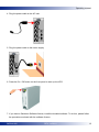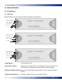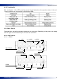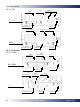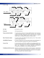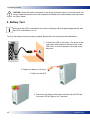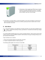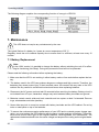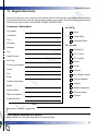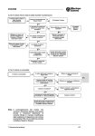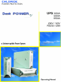
1
CHLORIDE
POWER PROTECTION
o Uninterruptible Power System
Desk POWER
Desk POWER
Desk POWER
300
500
650
Operating Manual
All rights, including rights of translation, reproduction by printing, copying or similar methods,
even of parts, are reserved.
Offenders will be liable for damages.
All rights, including rights created by patent grant
of registration of utility model or design, are
reserved.
Delivery subject to availability. Right of technical
modification reserved.
4
REV: 14/03/01
945014.066
Operating manual
Safety Instructions
7
Explanation of Symbols
8
1.
Introduction
9
2.
2.1
2.2
Unpacking the Unit & Contents
Unpacking the Unit
Package Contents
10
10
11
3.
Installation
11
4.
4.1
4.1.1
4.1.2
4.2
4.2.1
4.2.1.1
4.2.1.2
4.2.2
4.2.2.1
4.2.2.2
The Unit
Front Panel
Elements
Funcitonality
Rear Panel
230V Version
RS232
USB
120V Version
RS232
USB
14
14
14
15
15
15
15
16
16
16
17
5.
Battery Test
18
6.
Interfaces
19
7.
7.1
7.2
7.3
Maintenance
Battery Replacement
Storage
Cleaning
20
20
22
22
8.
Troubleshooting
22
9.
Technical Data
23
10.
Battery Back-up times
24
11.
Registration Form
25
12.
Chloride Address
27
945014.066
REV: 14/03/01
5
Operating manual
6
REV: 14/03/01
945014.066
Operating manual
Safety Instructions
CAUTION
Please read the following information carefully and save this manual for future reference! Disregard of
these safety notes may endanger life or health, as well as the function of the equipment and the safety
of your data.
· Whenever the on/off switch is on, there may be dangerous voltage present at the outlets. This is
because the battery supplies power even if the unit is not plugged into the wall outlet. The unit contains dangerous voltage.
· If the equipment is moved from a cold room to the operating room, please make sure that the equipment is absolutely dry before it is put into service.
· The equipment must be installed in an environment free from excessive dust and with enough air
flow. Do not expose equipment to moisture, excessive heat or direct sunlight.
· This equipment has a safety-tested power cable and may only be connected to a properly grounded
plug-socket.
· The power supply cord is intended to serve as the disconnection device. The outlet-socket must be
near the equipment and must be easily accessible.
· No data transmission lines should be connected or disconnected during a thunderstorm.
· Make sure no objects (e.g. pins, necklaces, paper lips, etc) get inside the device.
· Do not remove or unplug the input cord when the UPS is turned on. This action removes the safety
ground from the UPS and the connected load.
· The sum of the leakage current (protection conductor current) of the UPS and the connected devices must not exceed 3.5mA for the 230V series.
· The sum of the leakage current (protection conductor current) of the UPS and the connected devices must not exceed 0.75mA for the 120V series.
WARNING: There is a high risk of electric shock from the battery and a high short-circuit potential.
Remove all watches, rings and other metal objects and use only insulated tools when
replacing the battery.
WARNING: Do not throw the battery into a fire; it can explode.
WARNING: Do not open the battery. The electrolyte can be dangerous to the eyes and skin when spilled. It may be toxic.
945014.066
REV: 14/03/01
7
Operating manual
EC /UL/CSA Conformity Declaration
· The Chloride Desk Power 230V UPS complies with the regulations of the following European guidelines:
73/23/EEC Council guideline for EC countries concerning electrical apparatus within certain voltage tolerances, modified by the guideline RL 93/68/EEC of the Council.
89/336/EEC Council guideline for EC countries concerning electromagnetic compatibility, modified
by the guidelines RL 91/263/EEC, 92/31/EEC and 93/68/EEC of the Council.
· The Desk Power 120V complies with the regulations of the following American & Canadian guidelines:
UL US Council guideline concerning electrical apparatus within certain voltage tolerances, modified
by guideline UL1778.
CSA Council guideline for Canada concerning electrical apparatus within certain voltage tolerances,modified by guideline CSA C22.2 No.107.1.
Symbols
The meanings of the symbols used in this manual are as follows:
Pay particular attention to texts marked with this symbol. Failure to observe this warning may
endangers life, destroy systems, or lead to loss of data.
This symbol is followed by supplementary information, remarks and tips.
8
REV: 14/03/01
945014.066
Operating manual
1. Introduction
The Chloride DESK POWER series is based on the off-line principle. This means that the equipment
connected to the unit is powered by the mains after passing through diverse filters. This way, disturbances in the power mains are reduced, thereby improving the operational safety of the protected
equipment (PC, server systems, extended systems, etc.). In the event of a mains failure, the built-in
battery assumes the uninterrupted supply of energy.
The UPS indicates via acoustic (buzzer) and visual (LED) alarms that a mains failure has occurred.
The UPS has an auxiliary outlet with a filter for surges, electrical noise and transient voltage for noncritical loads, which are not battery powered.
This UPS is equipped with a protection device for voice and data lines. It protects fax, modem or local
network boards from cable disturbances (noise and dangerous voltage peaks).
945014.066
REV: 14/03/01
9
Operating manual
2. Unpacking the Unit & Contents
2.1 Unpacking the unit.
When opening the package, please follow this procedure:
1.- Place the packaging in a horizontal position following the arrow indications shown.
3.- Remove the top cover to the back.
5.- Remove the protection
2.- Open the front flap
4.- Remove the equipment
6.- Place the equipment in a working position
Note: All the material in the packaging has been made with recyclable materials.
Please Keep the packaging for future transportation.
10
REV: 14/03/01
945014.066
Operating manual
2.2 Package contents
The contents of a DESK POWER package are described below. Please ensure all the items have
been correctly received. It any of them have been damaged, please contact your supplier.
Once opened, please verify the following items included in the box. These are:
- UPS unit:
- Communication cable:
- 2 power cables with
IEC 320 or NEMA 5-15
plug for UPS outlet:
- Registration and software
download ticket:
- User manual:
3 Installation
Please read the following information before installing the UPS.
When installing the UPS, please consider the heavy weight of some components. Preferably,
they should be installed in the lower section of the cubicle. UPS systems consisting of several components must be installed so that the battery packs are mounted in the lower section.
Do not protect laser printers with the Battery Protected outlets because of the exceptionally
high power requirements of the heating elements.
945014.066
REV: 14/03/01
11
Operating manual
To correctly install the unit, please follow the procedure described below:
1.Connect the load (i.e. PC CPU, Monitor) to the UPS Battery Protected outlets. Appropriate loads are
those units that will require extend run time during blackouts.
2. Connect the selected load (i.e. printer, scanner) to the surge protected outlet. Appropriate loads are
those elements that demand surge protection, but that do not require extended runtime during
power outages.
3. If the UPS will provide communication to a computing system, connect the comms cable to the
UPS comm port and to the PC serial port
12
REV: 14/03/01
945014.066
Operating manual
4. Plug the power cable to the AC inlet.
5. Plug the power cable to the mains supply
6. Press the On / Off button on the front panel to start up the UPS.
7. If you have a Shutdown Software license, install the bundled software. To do this, please follow
the procedure enclosed with the software license.
945014.066
REV: 14/03/01
13
Operating manual
4. Unit elements.
4.1 Front Panel
4.1.1 Elements
Described below are the relevant elements located in the front panel.
Battery/Line Mode
Fault / Overload
Alarm Silence
On / Off
Battery/Line Mode
Fault / Overload
Alarm Silence
On / Off
Battery/Line Mode
Fault / Overload
Alarm Silence
On / Off
On/Off Button :
Turns On/Off the unit.
Alarm Silence button :
Silences the acoustic signals. This status will remain until either the
Off/On button is pressed or the Alarm Silence is pressed again.
Battery/Line Mode indicator:Shows the working status (Green-steady on mains, Green-blinking on
battery)
Fault/Overload indicator :
14
Indicates a battery failure or an overload condition
REV: 14/03/01
945014.066
Operating manual
4.1.2. Functionality
The combination of the LED’s and the acoustic signal determines the operation status of the unit.
These conditions are summarised in the following table:
4.2. Rear Panel
Depicted below, are all the elements located on the rear panel. Depending on the power, the voltage
and the type of communications port, the sets are as follows:
4.2.1. 230V Version.
4.2.1.1. RS232
Outlets
Batt. Protected
Outlets
Surge Protected
Protector
10A 250V AC
AC Inlet
300 - 500VA
Comm Port
Fax/Modem Protection
Outlets
Batt. Protected
AC Inlet
Outlets
Surge Protected
650VA
Fax/Modem Protection
945014.066
Protector
10A 250V AC
REV: 14/03/01
Comm Port
15
Operating manual
4.2.1.2. USB
Outlets
Surge Protected
Outlets
Batt. Protected
Protector
10A 250V AC
AC Inlet
300 - 500VA
Comm Port
Fax/Modem Protection
Outlets
Batt. Protected
AC Inlet
Outlets
Surge Protected
650VA
Protector
10A 250V AC
Fax/Modem Protection
Comm Port
4.2.2. 120V Version
4.2.2.1. RS232
Outlets
Batt. Protected
Outlets
Surge Protected
AC Inlet
300 - 500VA
Fax/Modem Protection
Outlet
Surge Protected
Protector
10A 250V AC
Protector
10A 250V AC
Comm Port
Outlets
Batt. Protected
650VA
Fax/Modem Protection
16
AC Inlet
REV: 14/03/01
Comm Port
945014.066
Operating manual
4.2.2.2. USB
Outlets
Batt. Protected
Outlets
Surge Protected
AC Inlet
300 - 500VA
Fax/Modem Protection
Outlet
Surge Protected
Protector
10A 250V AC
Protector
10A 250V AC
Comm Port
Outlets
Batt. Protected
650VA
Fax/Modem Protection
AC Inlet
Comm Port
AC Inlet
: Connection to mains
Protector
: 10A input protection
Surge protected outlets
: To protect devices that do not require additional back-up time but only
a clean and stable supply. (eg: Printers, scanners, etc.). On Mains
presence, the energy supplied by the outlets is filtered. In case of
mains failure no energy will be present at these outlets.
Batt. Protected outlets
: To protect loads with additional battery back-up time. These outlets
provide surge protection too.
10A/250VAC Protector
: In order to protect the unit from short-circuits and overcharges, an
input circuit breaker is present at the input of the equipment.
Comm. Port
: A communication port RS 232 or USB on the equipment allows computers to communicate with the UPS by using MopUPS Express software. (See -Registration and software download card).MopUPS
Professional is available for more advanced applications .
Fax/Modem/LAN Protection : Data line connections ( Fax / Modem / LAN connections ). Special line
filtered connections that provide protection to network or line communications. This feature cleans electrical noises out of the transmission, enhancing thus the connection speed.
945014.066
REV: 14/03/01
17
Operating manual
CAUTION: When the load is connected to the surge protected output on the rear panel, the
energy is taken directly from the mains therefore the loads will not have battery back-up if there
is a mains failure.
5. Battery Test
As soon as the UPS is connected to the mains, the battery will be charged independently whether UPS is switched on or not.
To verify the battery has been properly loaded, please follow the procedure described below:
1. Connect the UPS to the mains. The action of the
main relay will be heard at the same time of the
UPS' start. In normal operation, this step is already done.
2. Charge the battery for 8 hours.
3. Switch on the UPS.
4. The buzzer will beep continuously and both the red LED and
the green LED will light up for 2 seconds.
18
REV: 14/03/01
945014.066
Operating manual
5. If the battery is fully charged, the UPS will work in battery
mode for 3 seconds. The red LED will be off. The behaviour of the green LED and the buzzer are in accordance
with the battery mode with normal voltage.
6. If the battery is not fully loaded, the UPS will transfer to line mode immediately. No warning display is announced. Battery must then be verified by pressing the alarm silence button for more
than 2 seconds in line mode.
6. Interfaces
To prevent damage to the equipment and load connected, use only factory-supplied comms
cables or cable built according to factory specifications. A standard serial cable may damage
the equipment.
The Chloride DESK POWER series has two types of standard interface. These combine protocol data
transfer through a sequential RS232 interface or USB interface with signal exchange through a contact interface (UPS interface).
These interfaces can be used for:
1. Direct communication between the UPS and a computer.
2. Transfer of operational states to external systems.
The following table explains the connector Pin-out USB:
945014.066
REV: 14/03/01
19
Operating manual
The following diagram explains the corresponding function of every pin of RS232:
1
2
3
4
5
6
7
8
9
7. Maintenance
This UPS does not require any maintenance by the user.
The typical lifetime of a battery is 4 years at a room temperature of 25 °C.
Regularly check the unit's residual capacity time to ensure that it is sufficient, at least once every 12
months.
7.1 Battery Replacement
Note:
In the 120V version it is possible to change the battery without switching the unit off or affecting its functioning (Hot Swap). During this process the load will not be protected.
Please read the following information before replacing the battery:
1 - Make sure that the UPS is not working in either battery mode or line mode before replace the battery.
2 - The battery used in the UPS can produce dangerous voltages and high currents. Therefore, the
batteries may cause severe injury if their terminals come into contact with any tools or the UPS
cabinet. Be very careful to avoid electric shock and burns when replacing batteries.
3 - Disconnect the AC power cord and wait 30 seconds before servicing the battery. Battery circuit is
not isolated from AC input, hazardous voltage may exist between battery terminals and ground.
4 - Batteries contain caustic acids and toxic materials and can rupture or leak if mistreated. Remove
rings, wristwatches and other jewellery.
5 - Never allow any tool to come into contact with battery terminals and the UPS cabinet. Do not lay
tools or metal parts on top of the batteries.
6 - To ensure the continuous superior performance of your UPS and to maintain proper charger operation, you must replace the UPS batteries with the same number and type of batteries. These batteries must be the same type as the original batteries: valve-regulated, low maintenance. The
replacement batteries should have the same voltage and ampere-hour rating as the original batteries.
20
REV: 14/03/01
945014.066
Operating manual
7 - Assuming that the old batteries are fully charged. Use the same precautions you would use when
handling a new battery. Do not short battery terminals with a cable or tool! Batteries contain lead.
Many areas have regulations about disposing of used batteries. Please dispose of old batteries
properly. Do not dispose of batteries in a fire because the batteries could explode. Do not open or
mutilate batteries. Released electrolyte is harmful to the skin and eyes. It may be toxic.
8 -This equipment may produce ozone. Take precautions to ensure that the concentration of ozone is
limited to a safe value.
Please replace the battery by following these steps:
1. Remove the screw on the bottom side of the UPS and slide the door off.
2. Gently pull out the battery by grasping the tab.
3. Disconnect the two wires connecting the battery to the UPS.
4. Connect the battery wires to the new battery; red to positive (+), black to negative (-). Carefully
place the new battery into the case.
5. Slide the battery door back into place and secure with the screw removed in step1.
6. Install the UPS according to the procedure described in section 3
945014.066
REV: 14/03/01
21
Operating manual
7.2 Storage
For long time storage in moderate climates, the batteries should be charged for 8 hours every three
months. Repeat every two months in high temperature locations.
1. Connect the UPS to socket outlet with earthing contact or install the types for fixed connection
according to section 2.3 of this manual at an appropriate source. No matter stand-by switch is on
or off, it could be recharged properly.
2. Switch off if it has been turned on and pull out the mains plug after 8 hours. If necessary, then remove the connections of the UPS in an inverted sequence to what is described in section 3.
7.3 Cleaning
-
Before cleaning, you should switch off the UPS and pull the plug out of the socket outlet.
Do not use scouring powder or plastic-dissolving solution to clean the UPS.
Do not allow any liquid to get inside the UPS.
Clean the outside of the UPS housing by wiping with a dry or damp cloth.
8. Troubleshooting
If a problem occurs in despite of the high reliability of the device, please check the following table before calling the service centre.
· Is the UPS plugged into a correctly working outlet ?
· Has the protector tripped on the rear panel?
If the problem still exist, please have the following information to hand when you call for service:
· Information on the unit device (type, order number, serial number from type plate)
· Full description of problem (which load is connected, does the problem occur regularly or sporadically, etc.)
22
REV: 14/03/01
945014.066
Operating manual
9. Technical Data
945014.066
REV: 14/03/01
23
Operating manual
10. Battery Backup Times
Desk Power 300:
min.
Load
Desk Power 500:
min.
Load
Desk Power 650:
min.
Load
24
REV: 14/03/01
945014.066
Operating manual
11. Registration form.
Please fill out this form as completely as possible. None of the fields are required but the information
you provide will help us make our service better suited to your needs. The information you enter below
will never be used outside of CHLORIDE POWER PROTECTION.
Customer Information
For use in:
First Name
:
Last Name
:
Title
:
Company
:
Address
:
City
:
State/Province
:
Zip Code
:
Home
Small Office
Corporate Office
For use with:
Desktop PC
PC on LAN
PC on WAN
Server
Country of purchase:
Printer
Phone
:
Fax
:
Email
:
Scanner
Hub, Bridge, Router
CAD Workstation
Product information
Telecom
Model
:
Serial number
:
Date of purchase
:
Purchased form
:
Medical equipment
Security system
Process
Other:
Comments, remarks, suggestions...
Thank you for registering your product!
Note: Please fill in this form and submit to Chloride Office.
945014.001
REV: 14/03/01
25
Operating manual
26
REV: 14/03/01
945014.066
Operating manual
CHLORIDE WORLD HEADQUARTERS
Chloride Power Protection
George Curl Way
Southampton
Hampshire, SO18 2RY
United Kingdom
Telephone: +44 (0) 23 8061 0311
Facsimile: +44 (0) 23 8061 0852
[email protected]
AUSTRALIA
Chloride Hytek PTY LTD
Units C1A and C1B
Centrecourt Business Park
25-27 Paul Street North
North Ryde NSW 2113
Australia
Telephone: +61 2 9888 1266
Facsimile: +61 2 9888 1966
[email protected]
FRANCE
Chloride Industrial Systems
30 Avenue Montgolfier - BP 90
F-69684 Chassieu Cedex
France
Telephone: +33 4 7840 1356
Facsimile: +33 4 7890 5890
[email protected]
Chloride Power Protection
1 rue Felix Potin
ZA Les Belles Vues
91290 Arpajon
France
Telephone: +33 1 6926 1281
Facsimile: +33 1 6083 1816
[email protected]
Chloride Telecom Systems
ZA Les Rolandières
35120 Dol de Bretagne
France
Telephone: + 33 299 48 2068
Facsimile: + 33 299 48 3394
[email protected]
945014.001
GERMANY
Masterguard
Schallershofer Str. 141
D-91056 Erlangen
Germany
Telephone: +49 9131 9855 100
Facsimile: +49 9131 9855 270
[email protected]
ITALY
Chloride Silectron
Via Fornace 30
40023 Castel Guelfo
Bologna
Italy
Telephone: +39 054 2632 111
Facsimile: +39 054 2632 120
[email protected]
PORTUGAL
Chloride Power Protection
Rua dos Tercos 574
Zona Industrial de Canelas
4405 270 Canelas VNG. Oporto
Portugal
Telephone: +351 22 7151 210
Facsimile: + 351 22 7126 337
[email protected]
SPAIN
Chloride Boar
Azufre 8-10
Polígono Industrial Sur
28770 Colmenar Viejo, Madrid
Spain
Telephone : +34 91 848 84 00
Facsimile : +34 91 845 51 32
[email protected]
THAILAND
Chloride Power Electronics LTD
Panjathani Tower, 20th Floor
127/25 Nonsee Road
Chongnonsee, Yannawa
Bangkok 10120
Thailand
Telephone: + 662 6810 100
Facsimile: + 662 6810 109
[email protected]
Sebnem Sok. Nº 14, Kat: 3-4-7-8
81110 Bostanci Istambul
REV: 14/03/01
27
Operating manual
TURKEY
Masterguard
Sebnem Sok. Nº 14, Kat: 3-4-7-8
81110 Bostanci Istambul
Turkey
Telephone: +90 216 464 47 00
Facsimile: +90 216 464 47 15
[email protected]
UK
Chloride Power Protection
George Curl Way
Southampton
Hampshire, SO18 2RY
United Kingdom
Telephone: +44 (0) 23 8061 0311
Facsimile: +44 (0) 23 8061 0852
[email protected]
INTERNATIONAL SALES
Europe, Middle East and Africa
Chloride Power Protection
George Curl Way
Southampton
Hampshire, SO18 2RY
United Kingdom
Telephone: +44 (0) 23 8061 0311
Facsimile: +44 (0) 23 8061 0852
[email protected]
Chloride Industrial Middle-East (CIME)
PO Box 17693
Dubai
United Arab Emirates
Telephone: +971 (4) 881 8848
Facsimile:+971 (4) 881 4518
Oneac UK
18 & 20 Blacklands Way
Abingdon Business Park
Abingdon
Oxfordshire, OX14 1DY
United Kingdom
Telephone: +44 (0) 1235 534 721
Facsimile: + 44 (0) 1235 534 197
[email protected]
Latin America
Chloride Power Protection Latin America
Rua Arizona 1349
Brooklin Novo
Sao Paulo CEP 04567-002
Brazil
Telephone: +55 11 5505 4661
Facsimile: +55 11 5505 4832
[email protected]
USA
Chloride Power Protection
28430 N. Ballard
Lake Forest IL 60045
USA
Telephone: +1 800 239 2257
Facsimile: +1 800 833 6829
Asia Pacific
Chloride Power Protection
80 Marine Parade Road
#10-08 Parkway Parade
449269
Singapore
Telephone: +65 348 5288
Facsimile: +65 348 3400
[email protected]
Oneac Corporation
27944 North Bradley Road
Libertyville
Illinois 60048-9700
USA
Telephone: +1 847 816 6000
Facsimile: +1 847 680 5124
[email protected]
28
REV: 14/03/01
945014.066