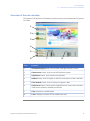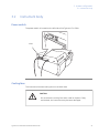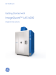
1
GE Healthcare
Typhoon™ FLA 7000
User Manual
Table of Contents
Table of Contents
1
Introduction ..........................................................................................................
1.1
1.2
1.3
1.4
5
Important user information .............................................................................................................
Regulatory information ......................................................................................................................
The Typhoon FLA 7000 laser scanner .........................................................................................
Typhoon FLA 7000 Control Software ...........................................................................................
5
6
9
10
Safety instructions ...............................................................................................
15
2.1
2.2
2.3
2.4
2.5
2.6
2.7
2.8
2.9
2.10
Introduction .............................................................................................................................................
General precautions ............................................................................................................................
Personal protection .............................................................................................................................
Laser safety .............................................................................................................................................
Radiation safety ....................................................................................................................................
Radiation hazard prevention ...........................................................................................................
Electric safety .........................................................................................................................................
Labels on Typhoon FLA 7000 ..........................................................................................................
Emergency procedures ......................................................................................................................
Recycling and disposal .......................................................................................................................
15
15
16
16
16
17
18
19
23
24
System configuration ..........................................................................................
25
3.1
3.2
3.3
Parts and functions ..............................................................................................................................
Instrument body ....................................................................................................................................
Accessories ..............................................................................................................................................
25
27
30
Installing and moving Typhoon FLA 7000 ........................................................
34
4.1
4.2
4.3
Site requirements ..................................................................................................................................
Transporting Typhoon FLA 7000 ...................................................................................................
Connections ............................................................................................................................................
34
35
35
Installing Typhoon FLA 7000 Control Software ..............................................
37
5.1
5.2
5.3
5.4
Installation sequence ..........................................................................................................................
Install Typhoon FLA 7000 Control Software (Windows XP) ...............................................
Install Typhoon FLA 7000 Control Software (Windows Vista) ..........................................
Install Typhoon FLA 7000 Control Software (Windows 7) ..................................................
37
37
41
45
6
Uninstalling and upgrading Typhoon FLA 7000 Control Software ..............
53
7
Registering, editing and deleting methods .....................................................
56
7.1
7.2
7.3
Registering a new method ...............................................................................................................
Editing a method ...................................................................................................................................
Deleting a method ................................................................................................................................
56
58
58
Filter module settings .........................................................................................
60
8.1
8.2
60
60
2
3
4
5
8
Registering a new filter name .........................................................................................................
Saving a filter combination ..............................................................................................................
Typhoon FLA 7000 User Manual 28-9607-62 AC
3
Table of Contents
8.3
8.4
Loading a filter combination ...........................................................................................................
Installing and replacing filters ........................................................................................................
61
62
Operation ..............................................................................................................
66
9.1
9.2
9.3
9.4
9.5
9.6
9.7
9.8
9.9
9.10
9.11
9.12
Operation overview .............................................................................................................................
Preparations before starting Typhoon FLA 7000 ...................................................................
Starting Typhoon FLA 7000 and Typhoon FLA 7000 Control Software .......................
Selecting the reading mode .............................................................................................................
Setting the reading conditions .......................................................................................................
Placing the object to be scanned on the stage ......................................................................
Placing the stage in Typhoon FLA 7000 .....................................................................................
Scanning the sample ..........................................................................................................................
Adjusting the display parameters .................................................................................................
Saving the image data using a different file name ...............................................................
Viewing the image file in the analysis application ................................................................
Turning off Typhoon FLA 7000 .......................................................................................................
66
66
67
68
69
69
73
74
75
76
76
76
10 Reading conditions, display parameters, and other settings ......................
77
9
10.1
10.2
10.3
Reading conditions explained ........................................................................................................
Display parameters explained ........................................................................................................
Other settings .........................................................................................................................................
77
81
82
11 About storage phosphor screens ......................................................................
85
11.1
11.2
11.3
11.4
11.5
Introduction .............................................................................................................................................
Compatible storage phosphor screens ......................................................................................
Handling precautions .........................................................................................................................
Preparing the storage phosphor screen ....................................................................................
Exposing the storage phosphor screen .....................................................................................
85
85
85
87
88
12 Maintenance .........................................................................................................
90
13 Troubleshooting ...................................................................................................
92
A
Default sample detection methods ..................................................................
97
B
Specifications ........................................................................................................
99
4
Typhoon FLA 7000 User Manual 28-9607-62 AC
1 Introduction
1
Introduction
In this chapter
This chapter contains important user information, and a general description of Typhoon
FLA 7000 and its intended use.
1.1
Important user information
Read this before using the
Typhoon FLA 7000
All users must read this entire manual to fully understand the safe use of Typhoon FLA
7000.
Intended use
Typhoon FLA 7000 is a fast laser scanner optimized for quantitative phosphorimaging,
ECL Plus Westerns, visible fluorescence and gel documentation.
Typhoon FLA 7000 is intended for research use only, and shall not be used in any clinical
procedures, or for diagnostic purposes.
Safety notices
This user documentation contains WARNINGS, CAUTIONS and NOTICES concerning the
safe use of Typhoon FLA 7000. See definitions below.
Warnings
WARNING
WARNING indicates a hazardous situation which, if not avoided,
could result in death or serious injury. It is important not to proceed
until all stated conditions are met and clearly understood.
Typhoon FLA 7000 User Manual 28-9607-62 AC
5
1 Introduction
1.1 Important user information
Cautions
CAUTION
CAUTION indicates a hazardous situation which, if not avoided,
could result in minor or moderate injury. It is important not to
proceed until all stated conditions are met and clearly understood.
Notices
NOTICE
NOTICE indicates instructions that must be followed to avoid
damage to the product or other equipment.
Notes and tips
Note:
A Note is used to indicate information that is important for trouble-free
and optimal use of the product.
Tip:
A tip contains useful information that can improve or optimize your
procedures.
Typographical conventions
Software items are identified in the text by bold italic text. A colon separates menu levels,
thus File:Open refers to the Open command in the File menu. Hardware items are
identified in the text by bold text (e.g., Power switch).
1.2
Regulatory information
This section lists the directives and standards that are fulfilled by the Typhoon FLA 7000
system.
6
Typhoon FLA 7000 User Manual 28-9607-62 AC
1 Introduction
1.2 Regulatory information
Manufacturing information
Requirements
Content
Name and address of manufacturer
GE Healthcare Bio-Sciences AB, Björkgatan 30, SE 751 84 Uppsala
Sweden
Name and ID of notified body
INTERTEK SEMKO AB, NB 0413
Place and date of declaration
Uppsala, Sweden, Sept. 2009
Identity of person authorized to sign
Declaration of Conformity
See EC Declaration of Conformity
International standards
This product fulfills the requirements of the following standards:
Standard
Description
EN 61010-1, IEC 61010-1, UL
61010-1, IEC 61010-2-81,
CAN/CSA-C22.2 No. 610101
Safety requirements for electrical
equipment for measurement,
control, and laboratory use
EN 61326-1
EMC emissions and immunity
requirements for electrical
equipment for measurement,
control and laboratory use
Harmonized with
2004/108/EC
EN-ISO 12100-1, 12100-2
Safety of machinery - Basic concepts, general principles for design
Harmonized with
2006/42/EC
EN-ISO 14121-1, 14121-2
Safety of machinery - Principles
of risk assessment
Harmonized with
2006/42/EC
EN 60825-1, IEC 60825-1
Safety of laser products
Harmonized with
2006/95/EC
USA 21 CFR, Chapter I, Subchapter J, Part 1040.10
Laser Products
Safety of laser products
VCCI Class A
FCC Part 15 B Class A
Notes
ICES-003 Class A
Typhoon FLA 7000 User Manual 28-9607-62 AC
7
1 Introduction
1.2 Regulatory information
CE Conformity
This product complies with the European directives listed in the table, by fulfilling the
corresponding harmonized standards. A copy of the Declaration of Conformity is available
on request.
Directive
Title
2006/42/EC
Machinery Directive (MD)
2006/95/EC
Low Voltage Directive (LVD)
2004/108/EC
ElectroMagnetic Compatibility (EMC) Directive
CE Marking
The CE marking and the corresponding Declaration of Conformity is valid for the
instrument when it is:
•
used as a stand-alone unit, or
•
connected to other CE marked GE Healthcare instruments, or
•
connected to other products recommended or described in the user documentation,
and
•
used in the same state as it was delivered from GE Healthcare, except for alterations
described in the user documentation.
Note:
This equipment has been tested and found to comply with the limits
for a Class A digital device, pursuant to Part 15 of the FCC Rules. These
limits are designed to provide reasonable protection against harmful
interference when the equipment is operated in a commercial
environment. This equipment generates, uses, and can radiate radio
frequency energy and, if not installed and used in accordance with the
instruction manual, may cause harmful interference to radio
communications. Operation of this equipment in a residential area is
likely to cause harmful interference in which case the user will be
required to correct the interference at his own expense.
This Class A digital apparatus complies with Canadian ICES-003. Cet
appareil numerique de la class A est conforme a la norme NMB-003
du Canada.
8
Typhoon FLA 7000 User Manual 28-9607-62 AC
1 Introduction
1.2 Regulatory information
Note:
This is a class A product. In a domestic environment this product may
cause radio interference in which case the user may be required to take
adequate measures.
Laser standards
This instrument is a Class 1 (IEC60825-1:2007/EN60825-1:2007) laser product.
The following lasers can be installed in Typhoon FLA 7000:
Laser and class
Wavelength
Maximum power
LD laser, class 3B
473 nm
20 mW (CW)
SHG laser, class 3B
532 nm
10 mW (CW)
LD laser, class 3B
635 nm
45 mW (CW)
LD laser, class 3B
650 nm
80 mW (CW)
Note:
The beam divergence of all laser modules is collimated.
Regulatory compliance of
connected equipment
Any equipment connected to the Typhoon FLA 7000 should meet the safety requirements
of EN 61010-1/IEC 61010-1, or relevant harmonized standards. Within EU, connected
equipment must be CE marked.
1.3
The Typhoon FLA 7000 laser scanner
The compact Typhoon FLA 7000 is an image analyzer that offers high performance,
multifunctionality, and high-speed reading. Benefits include:
Typhoon FLA 7000 User Manual 28-9607-62 AC
9
1 Introduction
1.3 The Typhoon FLA 7000 laser scanner
1.4
•
Detection of high-sensitivity autoradiographs using storage phosphor screens.
•
Four lasers and multiple filters enable the use of a variety of fluorescent dyes and
detection methods.
•
Data is aquired through high resolution, sensitivity and wide range linearity.
•
Compatibility with various types of samples, for example fluorescent labels,
fluorescent dyes, CBB stain, silver stain, X-ray film, and storage phosphor screens.
Typhoon FLA 7000 Control Software
System requirements
Parameter
Minimum requirement
Operating system
Microsoft™ Windows™ XP Professional SP3 (32-bit)
or
Microsoft Windows Vista Business SP2 (32-bit)
or
Microsoft Windows 7 Professional (32-bit)
Internal memory
1 GB
Processor
Intel Core 2 Duo processor
Hard drive
80 GB
Monitor resolution
1280 × 1024 pixels
Other requirements
One USB 2.0 port
DVD-ROM drive
10
Typhoon FLA 7000 User Manual 28-9607-62 AC
1 Introduction
1.4 Typhoon FLA 7000 Control Software
Overview of the main window
The Typhoon FLA 7000 Control Software is used to control, use and supervise the Typhoon
FLA 7000.
1
2
3
4
5
6
7
8
Part
Function
1
Phosphorimaging button: click to read a storage phosphor screen
2
Fluorescence button: click to read a fluorescent sample
3
Digitization button: click to perform digitization
4
Method button: click to register or erase a combination of laser and filter.
5
Filter Module button: click to change or register a filter.
6
Preferences button: click to set the image file format, scan mode, correction
mode and to enable or disable the ND filter.
7
Filter: displays the loaded filters.
8
Laser: displays the status of the loaded laser units
Typhoon FLA 7000 User Manual 28-9607-62 AC
11
1 Introduction
1.4 Typhoon FLA 7000 Control Software
Overview of the reader settings
window
10
1
11
2
7
3
8
4
5
6
9
12
13
14
15
Part
Description
1
Image folder: specify where to save the file after the reading.
2
File Name: enter the name of a file to save image data.
3
Comment: enter an optional comment. The comment is embedded
in the file where the image is saved, and can be viewed with the
analyzing software.
4
Method: set the method to use in the scan. Up to 4 scans can be
performed in a row, all with individual methods.
5
PMT: set the voltage of the photo-multiplier tube. The higher the
value, the higher the sensitivity.
Click to increase the number of
scans
Click to decrease the number of
scans
12
Typhoon FLA 7000 User Manual 28-9607-62 AC
1 Introduction
1.4 Typhoon FLA 7000 Control Software
Part
6
7
Description
Set the scanning area.
1
Select a stage in the drop-down menu.
2
Drag the red square to the desired position of the scanning
area.
3
Drag the sides of the red square as needed to adjust the size
of the scanning area.
Pixel Size: set the pixel size.
Choose a small pixel size for high quality images. Note that a small
pixel size setting increases the reading time and the size of the
image file.
8
9
Latitude: Specify the dynamic range.
•
L5 provides a larger detectable range than L4.
•
L4 provides a finer density gradation, if the signals of the sample
areas are in the correct range.
Mode: Specify the mode for the reading area borders.
•
Select Grid to limit the borders to the grid lines.
•
Select Free for an arbitrary area.
•
Select All to use the entire Fluor stage as the reading area.
10
Save Condition...: click this button to save the current reading
conditions in a file, if desired. For details, refer to the User Manual.
11
Load Condition...: click this button to load previously saved reading
conditions, if desired. For details, refer to the User Manual.
12
File Size: the estimated size of the result data file is presented.
13
Reading Time: the estimated time required for the scan is presented.
14
Top: return to the main window.
15
Start Scan: start the scan. The sample must be loaded before
starting a scan.
Typhoon FLA 7000 User Manual 28-9607-62 AC
13
1 Introduction
1.4 Typhoon FLA 7000 Control Software
System requirements
Parameter
Minimum requirement
Operating system
Microsoft™ Windows™ XP Professional SP3 (32-bit)
or
Microsoft Windows Vista Business SP2 (32-bit)
or
Microsoft Windows 7 Professional (32-bit)
Internal memory
1 GB
Processor
Intel Core 2 Duo processor
Hard drive
80 GB
Monitor resolution
1280 × 1024 pixels
Other requirements
One USB 2.0 port
DVD-ROM drive
14
Typhoon FLA 7000 User Manual 28-9607-62 AC
2 Safety instructions
2
Safety instructions
2.1
Introduction
The Typhoon FLA 7000 is powered by mains voltage and is used to image samples that
may be hazardous. Before installing, operating or maintaining the equipment, you must
be aware of the hazards described in the user documentation. Follow the instructions
provided to avoid personal injury or damage to the equipment.
2.2
General precautions
WARNING
Do not use the equipment if smoke, strange noises or strange odors
can be perceived, or if the equipment becomes unusually hot. This
may result in fire or electric shock.
Stop using immediately, turn off the power switch and unplug the
equipment from the power outlet. Contact your local GE Healthcare
representative to request repair.
WARNING
Do not damage the power supply cord by bending, twisting, heating
or allowing them to become pinned under the equipment. Using
damaged power cords could result in fire or electric shock.
If the power supply cords are damaged, contact your local GE
Healthcare representative for replacements.
WARNING
Do not place the equipment on unstable tables or on inclined
surfaces, as the equipment could be dropped or fall, resulting in
injury.
Typhoon FLA 7000 User Manual 28-9607-62 AC
15
2 Safety instructions
2.3 Personal protection
2.3
Personal protection
CAUTION
Always wear gloves, protective glasses and a lab coat or similar
when handling samples.
CAUTION
Always wear cotton gloves when handling storage phosphor
screens.
2.4
Laser safety
WARNING
Never detach the inner cover screwed to this instrument. If it is
detached, laser beam may leak with a risk of loss of vision.
CAUTION
Using procedures or adjustments other than those specified in this
manual may result in hazardous exposure to laser radiation.
2.5
Radiation safety
Radiation safety
This instrument is not equipped with any radioisotope (RI) or radiation generating unit,
and is therefore not regulated by radiation hazard prevention laws. However, the
instrument is capable of reading Storage phosphor screens which may be polluted by
radioisotopes (RI).
CAUTION
If radioisotope (RI) pollution occurs, stop use of the instrument
immediately and follow the instructions of your radiation
administrator.
16
Typhoon FLA 7000 User Manual 28-9607-62 AC
2 Safety instructions
2.6 Radiation hazard prevention
2.6
Radiation hazard prevention
Controlled area
Paragraph 1 of Article 1 of the Law Enforcement Rules for Prevention of Radiation Hazards
due to Radioisotope and so forth (Prime Minister's Office ordinance No. 56) defines the
controlled area as "a place where the dose equivalent related to external radiation
exceeds the dose equivalent determined by the Director General of the Science and
Technology Agency (hereinafter referred to as the Director General), the concentration
of radioisotope in the air exceeds the concentration determined by the Director General,
or the radioisotope density on the surface polluted by radioisotope exceeds the density
determined by the Director General."
Limit of superficial pollution
Paragraph 3 of Article 4 of Notice No. 15 of the Science and Technology Agency that
determines the quantity, etc. of radiating isotope specifies that the density of radioisotope
on the surface polluted by radioisotope must be one tenth of the density defined in Article
8.
Article 8 and Table 3 of this Notice define the limits as shown below:
1
Superficial density of radioisotope that radiates alpha rays: 4 Bq/cm2
2
Superficial density of radioisotope that does not radiate alpha rays: 40 Bq/cm2
Installation site of instrument
This instrument is capable of reading not only Storage phosphor screens but also
fluorescent pigment label samples (non-RI method). Therefore, it is recommended that
the user should install it outside the controlled area and use RI-indicated samples without
contacting them with Storage phosphor screens directly.
However, as described above, the Storage phosphor screen surface may be polluted by
radioisotope (RI), depending on the sample condition, since the instrument sticks the
sample to the 3H-compatible Storage phosphor screen surface and exposes it in an
auto-radiography experiment of the 3H label sample.
When a sample is in direct contact with a Storage phosphor screen, it is generally known
that the sample for making an auto-radiogram contains a relatively small quantity of
radioisotope. However, the degree of superficial pollution of the Storage phosphor screen
is greatly influenced by the dryness of the sample and dose of radioisotope in an
experiment and may exceed the limits mentioned in Limit of superficial pollution , on
page 17.
When the instrument reads a Storage phosphor screen with a polluted non-exposure
area, it may be polluted. The degree of such superficial pollution greatly differs with
users' operation conditions. Superficial pollution may exceed the limit mentioned above.
Note:
As mentioned above, install this instrument in the RI controlled area if
the user uses RI-indicated samples that will be in direct contact with
Storage phosphor screens.
Typhoon FLA 7000 User Manual 28-9607-62 AC
17
2 Safety instructions
2.6 Radiation hazard prevention
Removal from the controlled area
If it is necessary to move the instrument and its laboratory, which were installed and
have been used in the controlled area, from the controlled area, make sure that the
degree of the superficial pollution is below the limits mentioned in Limit of superficial
pollution above.
2.7
Electric safety
WARNING
Do not use the equipment with a power supply other than that
recommended. Fire and electric shock could result.
WARNING
Do not use the equipment within or near a sink, or in humid or dusty
environments. Fire and electric shock could result.
WARNING
Connect the power supply directly to a grounded wall power outlet.
The use of extension cords or multiple loads on one electrical outlet
could result in fire and electric shock.
CAUTION
Do not use the same power supply as that of large equipment such
as an air conditioner or centrifuge. Malfunction could result.
18
Typhoon FLA 7000 User Manual 28-9607-62 AC
2 Safety instructions
2.8 Labels on Typhoon FLA 7000
2.8
Labels on Typhoon FLA 7000
Typhoon FLA 7000 serial number
The Typhoon FLA 7000 serial number is located on a label on the back of the instrument.
123456
Symbols used in safety labels
Label
Meaning
Warning! Read the user documentation before using the system. Do not
open any covers or replace parts unless specifically stated in the user
documentation.
The system complies with the requirements for electromagnetic compliance
(EMC) in Australia and New Zealand.
The system complies with applicable European directives.
Typhoon FLA 7000 User Manual 28-9607-62 AC
19
2 Safety instructions
2.8 Labels on Typhoon FLA 7000
Labels concerning use of
hazardous substances
Label
Meaning
This symbol indicates that the waste of electrical and electronic equipment
must not be disposed as unsorted municipal waste and must be collected
separately. Please contact an authorized representative of the manufacturer for information concerning the decommissioning of equipment.
Labels concerning laser light
Label
Meaning
CAUTION! Avoid exposure to the laser
beam when the lid is open.
CAUTION! Class 3B Laser product when
open and interlock defeated. Avoid exposure to the beam.
Do not attempt to defeat the safety interlocks under the sample lid or behind the
filter door, or otherwise try to gain access
to the interior of the instrument through
any other opening. Exposure to laser light
can cause injury. Viewing the laser light
directly can cause blindness.
20
Typhoon FLA 7000 User Manual 28-9607-62 AC
2 Safety instructions
2.8 Labels on Typhoon FLA 7000
Labels at the front of Typhoon
FLA 7000
Typhoon FLA 7000 User Manual 28-9607-62 AC
21
2 Safety instructions
2.8 Labels on Typhoon FLA 7000
Labels at rear of Typhoon FLA
7000
123456
22
Typhoon FLA 7000 User Manual 28-9607-62 AC
2 Safety instructions
2.8 Labels on Typhoon FLA 7000
Labels on left side of Typhoon
FLA 7000
I : Power ON
O : Power OFF
USB
2.9
Emergency procedures
This section describes how to do an emergency shutdown of the Typhoon FLA 7000
instrument. The section also describes the results of a power failure.
Emergency shutdown
Step
Action
1
Click the Stop button in the Typhoon FLA 7000 Control Software.
2
Turn off the Typhoon FLA 7000 by pressing the power switch on the left side
of the instrument body.
3
Disconnect the power cord from the power outlet.
Typhoon FLA 7000 User Manual 28-9607-62 AC
23
2 Safety instructions
2.9 Emergency procedures
Power failure
The results of a power failure depends on the unit or units affected.
Unit affected by power failure
Results
Typhoon FLA 7000 instrument
•
The reading is interrupted immediately. The
instrument is in an undefined state.
•
The data collected up to the time of the power
failure is available in the file created when
starting the scan.
•
The computer shuts down immediately.
•
The run continues, but no data is saved.
Computer running the Typhoon
FLA 7000 Control Software
2.10 Recycling and disposal
General instructions for disposal
When taking the Typhoon FLA 7000 out of service, the different materials must be
separated and recycled according to national and local environmental regulations.
Specific instructions for disposal
Measure the superficial radio isotope pollution of the instrument body and storage
phosphor screen as mentioned in the radiation hazard prevention section of the User
Manual.
If the pollution level exceeds the limit, dispose of the instrument body as radioactive
waste. Otherwise, dispose of the materials according to applicable laws and regulations
for disposal of industrial waste.
24
Typhoon FLA 7000 User Manual 28-9607-62 AC
3 System configuration
3
System configuration
3.1
Parts and functions
The parts and their functions are explained separately in this chapter.
A
1
1
B
2
2
C
3
A
3
D
4
B
4
E
5
C
5
F
6
D
6
G
7
7
E
H
8
8
F
I
9
9
G
J
H
K
I
L
J
A
M
A
K
B
B
N
L
C
C
O
M
D
P
D
N
E
E
O
F
F
P
G
G
H
H
I
I
J
J
K
K
L
L
M
M
N
N
O
O
P
P
Part
Function
1
Power switch, located between the AC connector and the USB connector
2
Indicator lamps
3
Knob
4
Lid
Typhoon FLA 7000 User Manual 28-9607-62 AC
25
3 System configuration
3.1 Parts and functions
26
Part
Function
5
Setting block
6
Filter change door
7
Filter module slot
8
Filter module
9
Filter
10
Phosphor stage
11
Suction rod
12
Protection cover for storage phosphor screen
13
Fluor stage
14
Digitizing fluorescent plate
15
Membrane weight (included in Fluor stage)
Typhoon FLA 7000 User Manual 28-9607-62 AC
3 System configuration
3.2 Instrument body
3.2
Instrument body
Power switch
The power switch is located on the left side of the Typhoon FLA 7000.
Inlet
Cooling fans
The instrument has two cooling fans on the back side.
CAUTION
Do not block the cooling fans with a wall or objects. If they
are blocked, the instrument may become damaged.
Typhoon FLA 7000 User Manual 28-9607-62 AC
27
3 System configuration
3.2 Instrument body
Air intake fan
Exhaust fan
Indicator lamps
Three indicator lamps indicate the instrument status.
28
Typhoon FLA 7000 User Manual 28-9607-62 AC
3 System configuration
3.2 Instrument body
Stage setting block
Knob
Stage setting block
Stage door
Filter module
The filter module is located behind the filter door.
Filter module
Filter module slot
Filter change door
Typhoon FLA 7000 User Manual 28-9607-62 AC
29
3 System configuration
3.2 Instrument body
USB port
The USB port is located on the left side of Typhoon FLA 7000.
USB label
3.3
Accessories
Digitization plate (included)
The digitization plate is a fluorescent plate that emits light when exposed to a laser beam.
This plate is used when the digitization mode is used.
30
Typhoon FLA 7000 User Manual 28-9607-62 AC
3 System configuration
3.3 Accessories
Fluor stage (included)
The Fluor stage is used to read gels or membranes.
•
Place the gel or membrane directly on the glass of the Fluor stage.
•
Place the Fluor stage in the instrument.
Glass surface
A
1
B
2
C
3
D
4
E
5
F
6
G
7
H
8
9
I
J
K
L
A
M
B
N
C
O
P
D
E
F
G
H
I
J
K
L
M
N
O
P
Membrane weight (included)
The membrane weight is used to hold thin fluorescent samples flat against the Fluor
stage.
Multi stage (included)
The Multi stage is used to read gels with glass (gel merely supported by glass) or titer
plates.
•
Place the gel with the glass plate directly on the Multi stage, or place a titer plate on
the titer plate plugin attached to the instrument.
•
Place the titer plate on the Multi stage.
Typhoon FLA 7000 User Manual 28-9607-62 AC
31
3 System configuration
3.3 Accessories
Phosphor stage (included)
The phosphor stage is used when reading storage phosphor screens. The stage is
magnetic to hold storage phosphor screens.
•
Place the phosphor stage upside down on a flat surface.
•
Place the storage phosphor screen on the phosphor stage, with the reading surface
facing away from the phosphor stage.
•
Place the protective cover on top of the storage phosphor screen.
•
Flip the phosphor stage over.
•
Place the phosphor stage in Typhoon FLA 7000.
Storage phosphor screen
sticking side
A
1
B
2
C
A
3
D
B
4
5
E
C
6
F
D
7
G
E
8
H
F
9
I
G
J
H
K
C
G
P
H
P
F
O
G
O
E
N
F
N
D
M
E
M
C
L
D
L
B
J
B
K
A
I
A
H
I
I
J
J
K
K
L
L
M
M
N
N
O
O
P
P
Power cord (included)
Typhoon FLA 7000 uses a special AC power cable. Be sure to use power cables specified
in service manuals or by service personnel.
Suction rod (included)
The suction rod is used to lift up or place the the storage phosphor screen on the phosphor
stage.
Press the suction rod against the storage phosphor screen. Place a finger on the end of
the suction rod, then lift up the storage phosphor screen. Release the finger to release
the storage phosphor screen.
32
Typhoon FLA 7000 User Manual 28-9607-62 AC
3 System configuration
3.3 Accessories
Suction rod
Titer plate (TP) plugin (included)
The TP plugin is used when reading titer plate samples.
USB cable (included)
The USB cable is used to connect Typhoon FLA 7000 to a computer.
Typhoon FLA 7000 User Manual 28-9607-62 AC
33
4 Installing and moving Typhoon FLA 7000
4
Installing and moving Typhoon FLA
7000
CAUTION
Only authorized service personnel is allowed to install Typhoon FLA
7000. Contact your local GE Healthcare representative for help and
advice.
4.1
Site requirements
Note:
The Typhoon FLA 7000 is intended for indoor use only.
Parameter
Requirement
Power supply
100 to 240 V AC, 3.0 to 1.5 A
Line frequency
50 to 60 Hz
Placement
Stable, horizontal surface out of direct sunlight
Ambient temperature
+10 to +30°C
Humidity
20 to 75%, non-condensing
Maximum altitude
2000 m above sea level
Initial delivery inspection
Upon receiving Typhoon FLA 7000:
•
inspect the package for external damages
•
check that all items in the packaging list are included.
Should you find any external damages, or if any items on the packaging list are missing,
notify the delivery company and contact GE Healthcare for further advice.
Store Typhoon FLA 7000 in an environment according to Appendix B Specifications, on
page 99 until the product is unpacked and installed.
34
Typhoon FLA 7000 User Manual 28-9607-62 AC
4 Installing and moving Typhoon FLA 7000
4.2 Transporting Typhoon FLA 7000
4.2
Transporting Typhoon FLA 7000
CAUTION
Typhoon FLA 7000 must be secured before long distance transports.
Contact GE Healthcare for help and advice before transporting
Typhoon FLA 7000 long distances.
The Typhoon FLA 7000 weighs approximately 62 kg and requires at least two persons
to lift and move.
Precautions before moving the
instrument
4.3
Step
Action
1
Turn off the Typhoon FLA 7000.
2
Turn off the computer and any peripheral devices.
3
Disconnect the power cords and the USB connection.
Connections
CAUTION
Only authorized service personnel is allowed to install Typhoon FLA
7000. Contact your local GE Healthcare representative for help and
advice.
Communication
Step
Action
1
Connect a USB cable to the USB port on the left side of the Typhoon FLA
7000.
2
Connect the other end of the USB cable to a USB port on the computer.
Typhoon FLA 7000 User Manual 28-9607-62 AC
35
4 Installing and moving Typhoon FLA 7000
4.3 Connections
CAUTION
•
Do not connect any USB devices other than the Typhoon FLA
7000 to the computer in which the Typhoon FLA 7000 Control
Software is installed.
•
Use only the Typhoon FLA 7000 Control Software during
reading.
Electrical power
Connect the power cord of the Typhoon FLA 7000 to a grounded power outlet.
WARNING
Use only power cords delivered or approved by GE Healthcare.
36
Typhoon FLA 7000 User Manual 28-9607-62 AC
5 Installing Typhoon FLA 7000 Control Software
5
Installing Typhoon FLA 7000 Control
Software
Administrator privileges required
All tasks related to software installation or uninstallation require a computer account
with administrator privileges.
5.1
Installation sequence
Software installation is performed in the following sequence:
5.2
1
Install the USB control driver
2
Install the USB function driver (Windows XP only)
3
Install the Typhoon FLA 7000 Control Software
Install Typhoon FLA 7000 Control Software (Windows
XP)
Before you begin
Log in using a Windows account with administrator privileges.
Install the USB Control Driver
(Windows XP)
Step
Action
1
Disconnect Typhoon FLA 7000 from the computer.
2
Open the control panel and select Printers and Other Hardware.
3
Click Add Hardware to open Add hardware wizard.
4
Click the Next button in Add hardware wizard.
5
Select Yes, I have already connected the hardware and click the Next button.
Typhoon FLA 7000 User Manual 28-9607-62 AC
37
5 Installing Typhoon FLA 7000 Control Software
5.2 Install Typhoon FLA 7000 Control Software (Windows XP)
38
Step
Action
6
Select Add a new hardware device and click the Next button.
7
Select Install the hardware that I manually select from a list [Advanced]
and click the Next button.
8
Select Show All Devices and click the Next button.
9
Click the Have Disk button in the Add hardware wizard.
10
Insert the Typhoon FLA 7000 Control Software DVD and click the Browse
button.
11
Select to install the driver from the Typhoon FLA 7000 Control Software DVD.
Typhoon FLA 7000 User Manual 28-9607-62 AC
5 Installing Typhoon FLA 7000 Control Software
5.2 Install Typhoon FLA 7000 Control Software (Windows XP)
Step
Action
12
Open the USB Control folder.
13
Select the DevMng.inf file and click the Open button.
14
Click the OK button in the Install from disk dialog.
15
Click the Next button in the Add hardware wizard.
16
Click the Next button again.
17
Click the Continue Anyway button in the Hardware Installation dialog.
18
Click the Finish button to complete the driver installation.
Typhoon FLA 7000 User Manual 28-9607-62 AC
39
5 Installing Typhoon FLA 7000 Control Software
5.2 Install Typhoon FLA 7000 Control Software (Windows XP)
Install the USB function driver
(Windows XP)
Step
Action
1
Connect the computer and the Typhoon FLA 7000 with a USB cable and turn
ON the power switch of Typhoon FLA 7000. The scanner is automatically
detected by the computer.
2
In the Found New Hardware Wizard dialog, choose No, not this time.
3
Click the Next button in the Found New Hardware Wizard dialog.
4
Insert the installation DVD.
5
Select Install the software automatically (Recommended).
6
Click the Next button in the Found New Hardware Wizard dialog.
7
Click the Finish button to complete the installation.
Install Typhoon FLA 7000 Control
Software (Windows XP)
Step
Action
1
Insert the Typhoon FLA 7000 Control Software DVD.
2
Locate and double-click the file Typhoon FLA 7000.msi.
3
In the Typhoon FLA 7000 - InstallShield Wizard, click the Next button.
4
Read the license text. If the license agreement is not acceptable please
contact a GE Healthcare representative, see back cover of this manual for
contact information.
Select I accept the terms in the license agreement and click the Next button.
40
Typhoon FLA 7000 User Manual 28-9607-62 AC
5 Installing Typhoon FLA 7000 Control Software
5.2 Install Typhoon FLA 7000 Control Software (Windows XP)
5.3
Step
Action
5
Select destination folder in the dialog:
•
Click the Next button to install the software at the default folder C:\Program Files.
•
Click the Change button to install to a different folder.
6
Click the Install button in the installation dialog.
7
Click the Finish button to finish the installation of Typhoon FLA 7000 Control
Software.
Install Typhoon FLA 7000 Control Software (Windows
Vista)
Before you begin
Log in using a Windows account with administrator privileges.
Install the USB Control Driver
(Windows Vista)
Note:
During software installations, you may be asked to confirm your actions
in a dialog with the text Windows needs your permission to continue.
Enter an administrator password, if prompted, then click Continue to
proceed with the installation.
Step
Action
1
Disconnect Typhoon FLA 7000 from the computer.
2
Open the control panel and click Classic View in the upper left corner.
Typhoon FLA 7000 User Manual 28-9607-62 AC
41
5 Installing Typhoon FLA 7000 Control Software
5.3 Install Typhoon FLA 7000 Control Software (Windows Vista)
42
Step
Action
3
Open Add Hardware.
4
In the Add Hardware dialog, click the Next button.
5
Select Install the hardware that I manually select from a list (Advanced)
and click the Next button.
6
Select Show All Devices and click the Next button.
7
Click the Have Disk button.
8
Insert the Typhoon FLA 7000 Control Software DVD and click the Browse
button.
9
Select to install the driver from the Typhoon FLA 7000 Control Software DVD.
10
Select the USB Control folder and click Open.
Typhoon FLA 7000 User Manual 28-9607-62 AC
5 Installing Typhoon FLA 7000 Control Software
5.3 Install Typhoon FLA 7000 Control Software (Windows Vista)
Step
Action
11
Select the file DevMng and click the Open button.
12
Click the OK button in the dialog Install from disk.
13
Click the Next button in the wizard Add hardware.
14
Click the Next button once again.
15
The following warning is displayed. Proceed by cliking Install this driver
software anyway.
16
Click the Finish button in the Add Hardware wizard to complete the installation.
Install Typhoon FLA 7000 Control
Software and USB function driver
(Windows Vista)
Note:
During software installations, you may be asked to confirm your actions
in a dialog with the text Windows needs your permission to continue.
Enter an administrator password, if prompted, then click Continue to
proceed with the installation.
Step
Action
1
Insert the Typhoon FLA 7000 Control Software DVD.
Typhoon FLA 7000 User Manual 28-9607-62 AC
43
5 Installing Typhoon FLA 7000 Control Software
5.3 Install Typhoon FLA 7000 Control Software (Windows Vista)
Step
Action
2
Locate and double-click the file Typhoon FLA 7000.msi.
3
In the Typhoon FLA 7000 - InstallShield Wizard dialog, click the Next button.
4
Read the license text. If the license agreement is not acceptable, please
contact a GE Healthcare representative. See the back cover of this manual
for contact information.
Select I accept the terms in the license agreement and click the Next button.
5
Select destination folder in the dialog:
•
Click the Next button to install the software at the default folder C:\Program Files.
•
Click the Change button to install to a different folder.
6
Click the Install button.
7
If User Account Control (UAC) is enabled in Windows Vista, a dialog displays
the message An unidentified program wants access to your computer.
Click Allow.
8
Click Install this driver software anyway in the Windows Security dialog.
9
Click the Finish button.
The installation of Typhoon FLA 7000 Control Software is now completed.
44
Typhoon FLA 7000 User Manual 28-9607-62 AC
5 Installing Typhoon FLA 7000 Control Software
5.4 Install Typhoon FLA 7000 Control Software (Windows 7)
5.4
Install Typhoon FLA 7000 Control Software (Windows
7)
Before you begin
Log in using a Windows account with administrator privileges.
Disable the computer sleep
function
In order to prevent scanning errors, the computer should be set to never sleep as
described below.
1
Open the Control Panel and click System and Security. Click Change when the
computer sleeps below Power Options.
2
Select Never in the drop-down menu by Put the computer to sleep, then click Save
changes.
Typhoon FLA 7000 User Manual 28-9607-62 AC
45
5 Installing Typhoon FLA 7000 Control Software
5.4 Install Typhoon FLA 7000 Control Software (Windows 7)
Installation of the USB Control
Driver (Windows 7)
Note:
46
During software installations, you may be asked to confirm your actions
in a dialog with the text Windows needs your permission to continue.
Enter an administrator password, if prompted, then click Continue to
proceed with the installation.
1
Disconnect Typhoon FLA 7000 from the computer.
2
Open the control panel and click Hardware and Sound.
3
Click Device Manager under Devices and Printers.
Typhoon FLA 7000 User Manual 28-9607-62 AC
5 Installing Typhoon FLA 7000 Control Software
5.4 Install Typhoon FLA 7000 Control Software (Windows 7)
4
Select Action:Add legacy hardware.
5
In the Add Hardware dialog, click the Next button.
6
Select Install the hardware that I manually select from a list (Advanced) and click
the Next button.
Typhoon FLA 7000 User Manual 28-9607-62 AC
47
5 Installing Typhoon FLA 7000 Control Software
5.4 Install Typhoon FLA 7000 Control Software (Windows 7)
7
Select Show All Devices and click the Next button.
8
Click the Have Disk button.
Typhoon FLA 7000 Control Software
9
Insert the Typhoon FLA 7000 Control Software DVD and click the Browse button.
10 Select to install the driver from the Typhoon FLA 7000 Control Software DVD.
48
Typhoon FLA 7000 User Manual 28-9607-62 AC
5 Installing Typhoon FLA 7000 Control Software
5.4 Install Typhoon FLA 7000 Control Software (Windows 7)
11 Select the USB Control folder and click the Open button.
12 Select the file DevMng and click the Open button.
13 Click the OK button in the Install from disk dialog.
14 Click the Next button in the Add Hardware wizard.
15 Click the Next button once again.
Typhoon FLA 7000 User Manual 28-9607-62 AC
49
5 Installing Typhoon FLA 7000 Control Software
5.4 Install Typhoon FLA 7000 Control Software (Windows 7)
16 The following warning is displayed. Proceed by clicking Install this driver software
anyway.
17 Click the Finish button in the Add Hardware wizard to complete the installation.
Installation of the Typhoon FLA
7000 Control Software and USB
function driver (Windows 7)
Note:
50
During software installations, you may be asked to confirm your actions
in a dialog with the text Windows needs your permission to continue.
Enter an administrator password, if prompted, then click Continue to
proceed with the installation.
1
Insert the Typhoon FLA 7000 Control Software DVD.
2
Locate and double-click the file Control Software.msi.
Typhoon FLA 7000 User Manual 28-9607-62 AC
5 Installing Typhoon FLA 7000 Control Software
5.4 Install Typhoon FLA 7000 Control Software (Windows 7)
3
In the Control Software - InstallShield Wizard dialog, click the Next button.
4
Read the license text. If the license agreement is not acceptable, please contact a
GE Healthcare representative. See the back cover of this manual for contact
information.
Select I accept the terms in the license agreement and click the Next button.
5
Select the destination folder in the dialog:
•
Click the Next button to install the software in the default folder C:\Program
Files.
•
Click the Change button to select a different location.
Typhoon FLA 7000 User Manual 28-9607-62 AC
51
5 Installing Typhoon FLA 7000 Control Software
5.4 Install Typhoon FLA 7000 Control Software (Windows 7)
52
6
Click the Install button.
7
If User Account Control (UAC) is enabled in Windows Vista, a dialog displays the
message An unidentified programs wants access to your computer. Click Allow.
8
Click Install this driver software anyway in the Windows Security dialog.
9
Click the Finish button to complete the installation.
Typhoon FLA 7000 User Manual 28-9607-62 AC
6 Uninstalling and upgrading Typhoon FLA 7000 Control Software
6
Uninstalling and upgrading Typhoon
FLA 7000 Control Software
Before you begin
Log in using a Windows account with administrator privileges.
Uninstalling Typhoon FLA 7000
Control Software under Windows
XP
Step
Action
1
Open the control panel and select Add or Remove Programs.
2
Select Typhoon FLA 7000 and click the Remove button.
3
Confirm the uninstallation by clicking Yes when prompted.
Note:
Correction files created during calibration, such as shading data, are
required by the Typhoon FLA 7000 Control Software. They are not
deleted during the uninstallation, and remain in the Data folder of
Typhoon FLA 7000 Control Software folder.
Typhoon FLA 7000 User Manual 28-9607-62 AC
53
6 Uninstalling and upgrading Typhoon FLA 7000 Control Software
Uninstalling Typhoon FLA 7000
Control Software under Windows
Vista
Step
Action
1
Open the control panel and Select Uninstall a program under Programs.
2
Select Typhoon FLA 7000 and then click Uninstall.
3
Confirm the uninstallation by clicking Yes when prompted.
4
If User Account Control (UAC) is enabled in Windows Vista, a dialog displays
the message An unidentified program wants access to your computer.
Click Allow.
Uninstalling Typhoon FLA 7000
Control Software under Windows
7
54
Step
Action
1
Open the control panel and select Uninstall a program under Programs.
Typhoon FLA 7000 User Manual 28-9607-62 AC
6 Uninstalling and upgrading Typhoon FLA 7000 Control Software
Step
Action
2
Select Control Software and then click Uninstall.
3
Confirm the uninstallation by clicking Yes when prompted.
4
If User Account Control (UAC) is enabled in Windows 7, a dialog displays the
message An unidentified program wants to access your computer. Click
Allow.
Upgrading Typhoon FLA 7000
Control Software
Step
Action
1
Uninstall the current version of Typhoon FLA 7000 Control Software.
2
Install the new version of Typhoon FLA 7000 Control Software. Follow the
instructions in the installation chapter of Getting Started.
Typhoon FLA 7000 User Manual 28-9607-62 AC
55
7 Registering, editing and deleting methods
7
Registering, editing and deleting
methods
Note:
7.1
56
Method settings are registered by a serviceman upon installation. Under
normal circumstances, it is not necessary to change these settings.
Registering a new method
Step
Action
1
Click the Method button in the main window. The Method Settings dialog
box appears.
Typhoon FLA 7000 User Manual 28-9607-62 AC
7 Registering, editing and deleting methods
7.1 Registering a new method
Step
Action
2
Click the Add button. The following dialog box appears.
3
Select a laser in the Laser: drop-down box. You can select lasers that are
not currently loaded.
4
Select a filter in the Filter: drop-down box. You can select filters that are not
currently loaded.
5
Type a name in the Name: field.
6
Click the OK button. The list in the Method Settings window now contains
the new method with the selected laser and filter combination.
Note:
Methods containing lasers or filters that are not currently loaded cannot
be selected in the Reader Condition screen.
Typhoon FLA 7000 User Manual 28-9607-62 AC
57
7 Registering, editing and deleting methods
7.2 Editing a method
7.2
Editing a method
Step
Action
1
Click the Method button in the main window. The Method Settings dialog
box appears.
2
Select the desired method to edit.
3
Click the Edit button.
4
Enter the desired changes.
5
Click the OK button.
6
Finalize the changes by clicking the OK button in the Method Settings dialog
box.
Note:
7.3
Deleting a method
Note:
58
Default methods cannot be edited. Names of default methods are
surrounded by [square brackets].
Default methods cannot be deleted. Names of default methods are
surrounded by [square brackets].
Typhoon FLA 7000 User Manual 28-9607-62 AC
7 Registering, editing and deleting methods
7.3 Deleting a method
Step
Action
1
Click the Method button in the main window. The Method Settings dialog
box appears.
2
Select the desired method to delete.
3
Click the Delete button.
4
Click the Yes button. A confirmation dialog appears. (In the screenshots below,
the method name given is no name.)
5
Finalize the changes by clicking the OK button in the Method Settings dialog
box.
Note:
Typhoon FLA 7000 User Manual 28-9607-62 AC
To undo the filter deletion, click the Cancel button in the
Method Settings dialog box. Click Yes in the dialog box that
appears, see below.
59
8 Filter module settings
8
Filter module settings
Introduction
Filter module settings are registered by a serviceman upon installation. Under normal
circumstances, it is not necessary to register these settings.
When a filter is changed in the filter module of Typhoon FLA 7000, the new or changed
filter must be registered in the Typhoon FLA 7000 Control Software. A filter which has
not been registered can not be used for analysis and is not displayed in the Typhoon
FLA 7000 Control Software.
8.1
8.2
60
Registering a new filter name
Step
Action
1
Click the Filter Module button in the main window.
2
Click the Add button. The following dialog box appears.
3
Type the filter name in the Name: field.
4
Select an icon in the Icon: drop-down list.
5
Finalize the filter addition by clicking the OK button.
6
Click the OK button to return to the main window.
Saving a filter combination
Step
Action
1
Click the Filter Module button in the main window.
Typhoon FLA 7000 User Manual 28-9607-62 AC
8 Filter module settings
8.2 Saving a filter combination
8.3
Step
Action
2
Click the Save Filter Module... button.
3
Type a name for the filter combination in the File name: field.
4
Click the OK button.
5
Click the OK button to return to the main window.
Loading a filter combination
Step
Action
1
Click the Filter Module button in the main window.
2
Click the Load Filter Module... button.
3
Select a filter module to load in the Load Filter Module dialog box.
4
Click the OK button.
5
Click the OK button to return to the main window.
CAUTION
When removing the filter module, make sure to click the Filter
Module button and remove the filter module after the window
changes to the Filter Settings window.
If the filter module is forcefully removed, the area where the filter
comes in contact with the PMTs may be damaged.
Typhoon FLA 7000 User Manual 28-9607-62 AC
61
8 Filter module settings
8.4 Installing and replacing filters
8.4
Installing and replacing filters
Remove the filter module from
the scanner
Step
Action
1
Click the Filter Module button in the main window.
A status message appears. Wait until the message is closed before proceeding to the next step.
62
2
Open the filter change door.
3
Pull filter module straight out.
Typhoon FLA 7000 User Manual 28-9607-62 AC
8 Filter module settings
8.4 Installing and replacing filters
Remove and replace filters in the
filter module
Step
Action
1
Press the notch on the bottom of the filter module and pull out the filter.
2
Place the new filter in the filter module.
Push the new filter in until it locks in place.
Typhoon FLA 7000 User Manual 28-9607-62 AC
63
8 Filter module settings
8.4 Installing and replacing filters
Place the filter module in the
scanner
Step
Action
1
Open the filter change door.
2
Insert the filter module in the filter module holder.
3
Close the filter change door.
Register the filter change in
Typhoon FLA 7000 Control
Software
64
Step
Action
1
Click the Filter Module button in the main window.
Typhoon FLA 7000 User Manual 28-9607-62 AC
8 Filter module settings
8.4 Installing and replacing filters
Step
Action
2
Click the desired filter position on the filter tray.
3
Select the filter to be registered from Filter List.
4
Click the Insert button to register the filter.
Tip:
5
You can also drag the filter from Filter List to the desired
filter position.
Click the OK button.
Typhoon FLA 7000 User Manual 28-9607-62 AC
65
9 Operation
9
Operation
9.1
Operation overview
Using Typhoon FLA 7000 comprises a series of steps outlined below. Detailed explanations
are provided in subsequent chapters.
Turn on the Typhoon FLA 7000
Phosphorimaging samples
Start the computer and launch the Typhoon FLA 7000
Control Software
Expose the storage phosphor screen
Set the reading parameters
Place the stage and the sample in the Typhoon FLA
7000
Read the sample
9.2
Preparations before starting Typhoon FLA 7000
Checklist before starting
Typhoon FLA 7000
66
•
Typhoon FLA 7000 is placed on a sturdy, horizontal surface.
•
Typhoon FLA 7000 is connected to a grounded wall outlet.
•
The air intake fan on the rear side of Typhoon FLA 7000 is unobstructed.
•
The air exhaust fan on the rear side of Typhoon FLA 7000 is unobstructed.
•
There are no objects on top of Typhoon FLA 7000.
•
There is no stage in the stage rack.
Typhoon FLA 7000 User Manual 28-9607-62 AC
9 Operation
9.3 Starting Typhoon FLA 7000 and Typhoon FLA 7000 Control Software
9.3
Starting Typhoon FLA 7000 and Typhoon FLA 7000
Control Software
Start Typhoon FLA 7000
CAUTION
Do not insert a storage phosphor screen in Typhoon FLA 7000
before turning on the machine. If a storage phosphor screen is
detected during the self-diagnosis of the Typhoon FLA 7000, the
sensitivity of the storage phosphor screen may deteriorate and
reduce the quality of the scanned data.
Step
Action
1
Push the power switch on the left side of the body to the "I" position.
2
When the power switch is turned on, the indicator lamps change as shown
below.
After turning on the power
swich
During self-diagnosis or startup
adjustment
Ready for operation
Typhoon FLA 7000 User Manual 28-9607-62 AC
67
9 Operation
9.3 Starting Typhoon FLA 7000 and Typhoon FLA 7000 Control Software
Start Typhoon FLA 7000 Control
Software
Step
Action
1
Make sure that Typhoon FLA 7000 has completed the warm-up, after which
only the power lamp on the upper left panel on the front of the Typhoon FLA
7000 is lit.
2
Start Typhoon FLA 7000 Control Software from the Start menu, or use the
desktop shortcut.
3
The main window of the Typhoon FLA 7000 Control Software is displayed.
The condition is displayed in the Status area of the main window. Status
messages are as follows:
9.4
Message
Explanation
Disconnected
Cannot recognize Typhoon FLA 7000. Please check
connection and power.
Warm-up
Typhoon FLA 7000 is in self-diagnosis. Please wait.
Ready
The unit is ready to use.
Selecting the reading mode
Click the button that corresponds to the desired reading mode.
68
Typhoon FLA 7000 User Manual 28-9607-62 AC
9 Operation
9.4 Selecting the reading mode
To...
Click this button
Read a fluorescent sample
Read a phosphorimaging sample
Read a digitization sample
9.5
Setting the reading conditions
Set the reading conditions by following the instructions in Chapter 10 Reading conditions,
display parameters, and other settings, on page 77.
9.6
Placing the object to be scanned on the stage
CAUTION
Always wear gloves, protective glasses and a lab coat or similar
when handling samples.
Placing a gel sample on the Fluor
stage
Note:
•
The sample must not be thicker than 30 mm. For solutions, the
maximum height is 4 mm.
•
Make sure there are no bubbles or gaps on the contact surface.
Step
Action
1
Place the sample on the Fluor stage.
Typhoon FLA 7000 User Manual 28-9607-62 AC
69
9 Operation
9.6 Placing the object to be scanned on the stage
Placing a titer plate on the Multi
stage
Step
Action
1
Place the titer plate frame on the Multi stage.
2
Place the titer plate in the desired position in the titer plate frame.
Placing a gel sample with glass
on the Multi stage
70
Step
Action
1
Place a gel sample with glass on the Multi stage.
Typhoon FLA 7000 User Manual 28-9607-62 AC
9 Operation
9.6 Placing the object to be scanned on the stage
Step
Action
2
Carefully fold down the spring-loaded glass holders on the glass.
3
Tighten the screws on the glass holders as necessary.
Placing the storage phosphor
screen on the phosphor stage
CAUTION
Always wear cotton gloves when handling storage phosphor
screens.
Step
Action
1
Turn down the lighting in the room.
Typhoon FLA 7000 User Manual 28-9607-62 AC
71
9 Operation
9.6 Placing the object to be scanned on the stage
Step
Action
2
Place the cassette with the exposed storage phosphor screen next to the
phosphor stage.
A
B
C
D
E
F
G
H
I
J
K
A
L
B
M
C
N
D
O
E
P
F
G
H
I
J
K
L
M
N
O
P
3
4
72
Pick up the storage phosphor screen and move it to the phosphor stage.
1
Press one end of the suction rod against the storage phosphor screen.
2
Cover the other end of the suction rod with a finger.
3
Lift up the storage phosphor screen by the suction rod, and place the
storage phosphor screen on the phosphor stage.
4
Release the storage phosphor screen by releasing your finger from the
suction rod.
Place the storage phosphor screen on the back of the phosphor stage, with
the white or blue reading surface of the storage phosphor screen facing up.
Typhoon FLA 7000 User Manual 28-9607-62 AC
9 Operation
9.7 Placing the stage in Typhoon FLA 7000
9.7
Placing the stage in Typhoon FLA 7000
Placing the Fluor or Multi stage
in the Typhoon FLA 7000
Step
Action
1
Pull the knob up and open the lid.
2
Position the stage so that the black triangle mark is aligned with the corresponding mark on the setting block. Fit the setting block pin in the hole of
the stage.
3
Pull the knob up and close the lid.
Typhoon FLA 7000 User Manual 28-9607-62 AC
73
9 Operation
9.7 Placing the stage in Typhoon FLA 7000
Placing the phosphor stage in
Typhoon FLA 7000
9.8
Step
Action
1
Pull the knob up and open the lid.
2
Position the stage so that the black triangle mark is aligned with the corresponding mark on the setting block.
3
Fit the setting block pin in the hole of the stage.
4
Pull the knob up and close the lid.
Scanning the sample
Click the Start Scan button to start reading the sample. The scanning progress window
opens.
74
Typhoon FLA 7000 User Manual 28-9607-62 AC
9 Operation
9.8 Scanning the sample
9.9
Note:
If you click the Stop button during reading, the part that has not been
read yet will be saved as an image with a data value of 0 (light intensity
of 0).
Note:
When you click the Stop button, the reading is aborted. You cannot
start reading again from the location where reading stopped.
Adjusting the display parameters
Step
Action
1
Adjust the display parameters if desired. Follow the instructions in Section10.2
Display parameters explained, on page 81.
2
Click Return to return to the Reader Settings screen.
Typhoon FLA 7000 User Manual 28-9607-62 AC
75
9 Operation
9.10 Saving the image data using a different file name
9.10 Saving the image data using a different file name
Step
Action
1
After scanning the sample, click the Save as... button. The following dialog
opens.
2
Type a file name in the File name: field.
3
Select a file format in the Save as type: drop-down list.
4
Save the image file by clicking the Save button.
9.11 Viewing the image file in the analysis application
Click the Launch button in the to open the image file in the registered analysis application.
Note:
If no analysis application is registered in Typhoon FLA 7000 Control
Software, the Launch button is greyed out and inactive. If desired,
register or change the analysis application.
9.12 Turning off Typhoon FLA 7000
76
Step
Action
1
Turn off Typhoon FLA 7000 by pressing the power switch on the left side of
the instrument body.
Typhoon FLA 7000 User Manual 28-9607-62 AC
10 Reading conditions, display parameters, and other settings
10 Reading conditions, display
parameters, and other settings
10.1 Reading conditions explained
Save condition
Load condition
Image folder
File Name
Pixel size
Comment
Latitude
Method
Stage
PMT
Sampling a
Mode
File Size
Reading Tim
Top
Start Scan
Image folder
Specify where to save the file after the reading.
Note:
When reading more than once and reading of 1ch/2ch is implemented
simultaneously, a folder with a name set by File Name is created
automatically at the specified position and the image data will be saved
in the folder.
Typhoon FLA 7000 User Manual 28-9607-62 AC
77
10 Reading conditions, display parameters, and other settings
10.1 Reading conditions explained
File Name
Enter the name of a file to save image data. This field is mandatory in order to start
reading a sample.
Note:
The method name is automatically added to the specified name and is
saved to a file.
Comment
Enter an optional comment. The comment is embedded in the file where the image is
saved, and can be viewed with the analyzing software.
Method
Set the method to use in the scan.
From the pull-down menu, select the method that
corresponds with the sample. The selected laser
and filter combination is displayed below the
menu.
In fluorescent mode, up to 4 scans can be performed in a row, all with individual methods.
PMT
You may set the voltage to be applied to the photo-multiplier tube (PMT) as an integral value within
the predetermined range. The larger the value is,
the higher the sensitivity.
500V
Value
Small
Low
78
1000V
Large
Sensitivity
High
Typhoon FLA 7000 User Manual 28-9607-62 AC
10 Reading conditions, display parameters, and other settings
10.1 Reading conditions explained
Plus and minus buttons
(fluorescent mode only)
Click to increase the number of scans
Click to decrease the number of scans
Top button
Click this button to return to the main window.
Save condition
Click this button to save the current conditions settings to a file.
Save the current conditions by clicking Save Condition... A text dialog opens. Enter a
name for the conditions in the text field and click OK to save.
Load condition
Click this button to load previously saved conditions. Clicking the button opens a dialog
box with a list of previously saved condition sets.
Load a set of stored conditions by selecting it in the list, then click OK.
Remove a set of stored conditions by selecting it, then click Remove... Confirm the removal
by clicking the Yes button in the next dialog box.
Pixel size
Set the pixel size for reading.
Click to select from one of the four types. A sample
with a smaller pixel size is analyzed in finer detail.
200
Typhoon FLA 7000 User Manual 28-9607-62 AC
100
50
Short
Reading Time
Small
Image File Size
m 25
Long
Large
79
10 Reading conditions, display parameters, and other settings
10.1 Reading conditions explained
Latitude
This setting specifies the dynamic range. The dynamic range that can be detected is
larger with L5 than with L4. If the signals of the sample are in the L4 range, the density
gradation is represented in more detail if L4 is selected.
Stage
Select the stage which will be used in the scan. The image under Sampling Area changes
to reflect the selection.
Sampling area
Displays the area or areas to be scanned as red boxes.
•
Change the size of the area or areas to be scanned by clicking and dragging the
edges of the red box with the mouse.
•
Change the position of the area or areas to be scanned by clicking and dragging the
red box with the mouse.
Mode
Sets the selection behavior of Sampling area.
Setting
Description
Grid
The sampling area is increased or decreased in steps corresponding to
the grid of the stage or the positions of the titer plate plugin.
Free
The sampling area is increased or decreased in a stepless fashion.
All
The sampling area is expanded to the whole readable surface of the stage
or titer plate plugin is selected.
File Size
This area displays the estimated size of the image file as determined by the current
settings.
80
Typhoon FLA 7000 User Manual 28-9607-62 AC
10 Reading conditions, display parameters, and other settings
10.1 Reading conditions explained
Reading Time
This area displays the estimated reading time as determined by the current settings.
Scan button
Click this button to start scanning the sample or samples using the current reading
conditions.
10.2 Display parameters explained
Upper limit
Lower limit
Intensity graph
Curve
Auto Range Scope
Magnification
Magnification
Select a ratio to zoom in and out of the display area.
If the magnification is high, scroll bars appear on the right and bottom edges of the
display area. Use these scrollbars to view different parts of the display area.
There are several ways to zoom in and out of the display area, see the table below.
Zooming in
Zooming out
Click the + magnifying glass symbol and
left-click the display area
Click the + magnifying glass symbol and
right-click the display area
or
or
Click the - magnifying glass symbol and
right-click the display area
Click the - magnifying glass symbol and
left-click the display area
or
or
select a magnification ratio further down
the Magnification drop-down list.
select a magnification ratio further up
the Magnification drop-down list.
Typhoon FLA 7000 User Manual 28-9607-62 AC
81
10 Reading conditions, display parameters, and other settings
10.2 Display parameters explained
Intensity graph
The intensity graph displays the intensity levels of the image in histogram format.
The Low and High values below the graph correspond to the range of light intensities
displayed. These values are displayed in the graph as vertical red lines. To display a larger
or smaller interval of light intensities, drag the lines using the mouse to adjust the Low
and High values.
Curve
Select the type of tone curve used in the intensity graph.
Setting
Description
Exponential
The light intensities are displayed using an exponential tone curve.
Linear
The light intensities are displayed using a linear tone curve.
Sigmoid
The light intensities are displayed using a sigmoid (S-shaped) tone
curve.
Auto Range Scope
Check this option to automatically adjust the range of light intensities for optimum display
results.
10.3 Other settings
Preferences
Click the Preferences... button in the main window to display a tabbed dialog box, where
various options related to sample reading can be viewed and changed. Not all options
are relevant in all scanning modes.
82
Typhoon FLA 7000 User Manual 28-9607-62 AC
10 Reading conditions, display parameters, and other settings
10.3 Other settings
Setting
Description
Correction
Mode
Auto: Use specific image shading correction data that were adjusted
in accordance with each laser.
Manual: The correction method must be selected individually in the
Reader Settings window.
Note:
ND Filter
The correction mode settings list is registered by
a serviceman. Please contact the dealer where
you purchased Typhoon FLA 7000, or contact GE
Healthcare.
Enables the use of an ND filter to adjust the light intensity. Use the
ND filter if the signal from the sample is very strong.
Select On to enable the ND filter. Select Off to disable the ND filter.
Scan Mode
Determines the scanning speed.
Standard Mode: 200 μm/210 s, 100 μm/210 s, 50 μm/330 s, 25
μm/450 s.
Quick Mode: 200 μm/150 s, 100 μm/150 s, 50 μm/210 s, 25 μm/330
s.
File Format
Determines the file format used to save the reading data.
Gel Image File (*.gel): The standard file format is a .gel file which
contains square root encoded pixel data.
Gel Image File (*.gel) + Tiff Image File (*.tif): In combination with a
.gel file, a read image can also be saved in TIFF file format. For TIFF
files, image data type is always set to Linear format.
Launch Application
Typhoon FLA 7000 User Manual 28-9607-62 AC
Contains the path to the application used to analyze the data.
Select the analysis application by clicking the Select... button. Then
browse to the software executable and click OK.
83
10 Reading conditions, display parameters, and other settings
10.3 Other settings
User account specific settings
Changes to the settings in the Preferences dialog affect only the current Windows user
account. Changes made using a different user account do not affect the current user
account.
84
Typhoon FLA 7000 User Manual 28-9607-62 AC
11 About storage phosphor screens
11 About storage phosphor screens
11.1 Introduction
The Storage phosphor screen is a radiation energy memory type, two-dimensional
sensor, which has an image recording layer consisting of polyester base material densely
coated with accelerated phosphorescent fluorescent material of fine crystals.
•
Exposure
A Storage phosphor screen accumulates and stores radiation energy while it is
exposed. It is exposed in close contact with an RI sample in a cassette like X-ray film.
•
Scanning
The recording surface of an exposed Storage phosphor screen is scanned with a
laser beam inside Typhoon FLA 7000 and emits fluorescent light according to the
exposure level. A photo-multiplier tube (PMT) detects the fluorescent light and converts
it into electric signals. A radiation image recorded on the Storage phosphor screen
during exposure is read as digital image information at the maximum resolution of
25 µm per pixel (40 pixels/mm) and recorded in the analyzer unit.
•
Erasure
You may reuse a general-purpose Storage phosphor screen by erasing an
after-image.
11.2 Compatible storage phosphor screens
Storage phosphor screens with magnetic layers for sticking on the phosphor stage are
usable.
11.3 Handling precautions
Check the exposure environment
NOTICE
Avoid exposing storage phosphor screens in places where the
environmental radiation may be increased, for example rooms with
concrete walls or in basements.
Do not stack cassettes during exposure.
Typhoon FLA 7000 User Manual 28-9607-62 AC
85
11 About storage phosphor screens
11.3 Handling precautions
Wear gloves
CAUTION
Always wear cotton gloves when handling storage phosphor
screens.
Use a suction rod when taking the storage phosphor screen out of the cassette. Prying
the storage phosphor out may result in the edge peeling off, making the storage phosphor
screen unusable.
Handle the storage phosphor
screen carefully
•
Do not scratch or bend the storage phosphor screen.
•
Keep the storage phosphor screen free from dust.
Protect the storage phosphor
screen from water and volatile
solvents
•
Dry the sample thoroughly before exposing it.
•
Wrap wet samples in plastic film and make sure that no liquid exits. Use double layers
if the sample contains volatile solvents.
•
If water enters the Storage phosphor screen, the sensitivity of the storage phosphor
screen is reduced.
•
Volatile solvents may deform the protective film on the storage phosphor screen.
Protect exposed storage
phosphor screens from light
Protect exposed storage phosphor screens from light until the reading is finished.
86
Typhoon FLA 7000 User Manual 28-9607-62 AC
11 About storage phosphor screens
11.3 Handling precautions
Store the storage phosphor
screen correctly
Remove the storage phosphor screen from the Typhoon FLA 7000 main unit when not
in use. Store the storage phosphor screens in a horizontal position, protected from
moisture.
11.4 Preparing the storage phosphor screen
Procure necessary tools and
items
Prepare by acquiring the following items:
•
Storage phosphor screen cassette
•
Radio isotope labeled samples
•
Gloves
•
Plastic film
•
Soft, lint-free tissues
•
Ethanol
Clean the storage phosphor
screen and the cassette
Clean the surface of the storage phosphor screen and the inside of cassette with a soft
tissue to remove dust and stains.
Erase the storage phosphor
screen
The FLA Image Eraser can erase the storage phosphor screen in around 15 minutes, if
it is not overly exposed. For details, refer to the FLA Image Eraser User Manual.
Typhoon FLA 7000 User Manual 28-9607-62 AC
87
11 About storage phosphor screens
11.4 Preparing the storage phosphor screen
Dim the lighting
•
Dim the ambient light to 20 lux or less before opening or moving the storage phosphor
screen without a cover.
•
Protect the phosphor stage with the protective cover when removing an exposed
storage phosphor screen from the cassette and placing it on the Phosphor stage.
Set the exposure time
Set the exposure time so that the exposure finishes right before the reading starts.
Note:
The exposure time of the storage phosphor screen is approximately
one twentieth of the time required for X-ray film. Take this into
consideration when setting the initial exposure time.
Tip:
For increased image quality, minimize the time between exposing the
storage phosphor screen and reading it with the Typhoon FLA 7000.
11.5 Exposing the storage phosphor screen
Step
Action
1
Erase the storage phosphor screen completely.
2
Wrap the radio isotope sample with plastic film. Make sure not to wrinkle
the wrapping film.
Note:
3
88
When using a tritium storage phosphor screen to detect
tritium, place the sample directly on the storage phosphor
screen. A tritium storage phosphor screen can be used
only once.
Open the top cover of the cassette. Unlock the cassette by sliding the buttons
on both sides up.
Typhoon FLA 7000 User Manual 28-9607-62 AC
11 About storage phosphor screens
11.5 Exposing the storage phosphor screen
Step
Action
4
Place the sample on the cassette. Make sure that the sample surface faces
up.
Note:
Keep the radio imaging sample away from the edge of the
storage phosphor screen. Otherwise, the recorded data
may become corrupted.
5
Place the storage phosphor screen in the cassette, with the exposure surface
of the storage phosphor screen facing the sample. Make sure that the notch
of the storage phosphor screen is in the front left corner of the cassette as
shown below.
6
Close the cover of the cassette. Press on the cover until it clicks into place.
Typhoon FLA 7000 User Manual 28-9607-62 AC
89
12 Maintenance
12 Maintenance
Cleaning the outside of Typhoon
FLA 7000
Clean the outside with a moist soft cloth and a mild detergent. Wipe afterwards with a
dry soft cloth.
Maintenance of the SHG laser
If you use the SHG laser in the Typhoon FLA 7000, it will require periodical calibration.
When the Typhoon FLA 7000 is switched on, it automatically executes calibration. You
do not need to do a manual calibration if the Typhoon FLA 7000 is used at least once a
month.
CAUTION
Activate the Typhoon FLA 7000 at least once every 30 days
to execute calibration. This calibration ensure that the SHG
laser operates properly. Failure to calibrate the Typhoon FLA
7000 every 30 days reduces the lifespan of the SHG laser.
Operation procedures:
90
1
Turn on the Typhoon FLA 7000 and the computer.
2
Wait until warm-up and self-diagnosis is completed, and the scanner is ready. Only
the power lamp on the upper left panel is lit. The automatic calibration has now been
performed.
3
Turn off the Typhoon FLA 7000 and the computer.
Typhoon FLA 7000 User Manual 28-9607-62 AC
12 Maintenance
Cleaning the stage
CAUTION
Wear gloves to prevent direct contact with chemical substances.
Step
Action
1
Remove the stage from the main body of the instrument.
2
Wipe the stage with a sponge moistened with a fluorescence-free neutral
detergent.
3
Thoroughly rinse the stage with water and dry with a lint-free cloth.
4
Place the stage in the main body of the instrument.
Storing the Fluor or Multi stage
Store the Fluor or Multi stage in the original packaging when they are not in use. DO
NOT store stages inside Typhoon FLA 7000.
Typhoon FLA 7000 User Manual 28-9607-62 AC
91
13 Troubleshooting
13 Troubleshooting
This chapter describes various problems that can foreseeably occur with the Typhoon
FLA 7000 Control Software. Suggestions of possible countermeasures are given.
Do the following if an error occurs.
Step
Action
1
Take note of the error code and error message on the monitor.
2
Turn off the power to Typhoon FLA 7000 and the computer, then turn them
on again after about ten seconds.
3
Try to perform the action again. If the error persists, contact your GE
Healthcare representative.
General errors and warnings
Error message
Meaning and countermeasure
Failed to open User Manual. Please note that
a PDF reader (e.g. Adobe Reader) is needed.
The software required to read the
online PDF documentation is missing.
Failed to open End-User License Agreement.
Please note that a PDF reader (e.g. Adobe
Reader) is needed.
Countermeasure: Install software
for viewing PDF documents.
Failed to open Getting Started. Please note
that a PDF reader (e.g. Adobe Reader) is
needed.
The disk capacity is insufficient.
The available disk space is insufficient.
Countermeasure: Free up disk
space on the computer.
Countermeasure: Store the data on
a different disk.
No disk space.
92
See above.
Typhoon FLA 7000 User Manual 28-9607-62 AC
13 Troubleshooting
Errors and warnings in the main
window
Error message
Meaning and countermeasure
Cannot detect Typhoon FLA 7000.
Please check connection and
power.
The scanner is not detected.
Countermeasure: Check that the scanner is
turned on and connected to the computer.
Errors and warnings in the Filter
Module Settings window
Error message
Meaning and countermeasure
Filter module has not been set up.
Click the filter module button to
set up the filter module.
The filter module is not installed or properly
configured.
Please enter a filter name.
The filter has no name.
Countermeasure: Install the filter module. See
Section 8.4 Installing and replacing filters, on
page 62.
Countermeasure: Type a name in the Name
field.
The filter name has already been
used. Please change the name.
The name of the filter is being used for another
filter.
Countermeasure: Choose another name for
this filter, or change the name for the filter already having this name.
The maximum number of the filters
you can register is 50. Please
delete an unnecessary filter before
registeringa a new filter.
Typhoon FLA 7000 User Manual 28-9607-62 AC
No more filters can be stored in the software.
Countermeasure: Delete a filter before storing
a new one.
93
13 Troubleshooting
Errors and warnings in the
Method Settings window
Error message
Meaning and countermeasure
Please input a method name.
No name has been assigned to the method.
Countermeasure: Type a method name in the
Name field.
The maximum number of the
methods is 50.
The maximum number of methods are stored. No
more methods can be registered.
Countermeasure: Use an existing method, or delete
a method before registering a new one.
This method name has been
already used. Please change
the name.
The assigned name is being used by a different
method.
Countermeasure: Type a different name in the
Name field.
Errors and warnings in the
Reader Settings window
94
Error message
Meaning and countermeasure
Failed to retrieve image data
from the scanner. Check the
scanner connection.
There was a problem transferring data to the computer.
Countermeasure: Check the scanner connection
to the computer.
Cannot detect Typhoon FLA
7000. Please check connection and power.
The scanner was not detected by the computer.
Typhoon FLA 7000 imager is
running self-diagnosis mode.
Please wait.
The self-diagnosis of Typhoon FLA 7000 is running.
Countermeasure: Check that Typhoon FLA 7000 is
properly connected. Follow the instructions in
Chapter 4 Installing and moving Typhoon FLA 7000,
on page 34.
Countermeasure: Wait until the self-diagnosis is
finished, the proceed with the scan.
Typhoon FLA 7000 User Manual 28-9607-62 AC
13 Troubleshooting
Error message
Meaning and countermeasure
A laser error was detected.
Please retry the scan, or
contact service.
There was an error with the laser.
Countermeasure: Try to scan again.
Countermeasure: Restart the instrument and Typhoon FLA 7000 Control Software, then try to run
the scan again.
Countermeasure: Scan using a different laser.
Please select image folder.
No image folder is selected.
Countermeasure: Select an image folder by clicking
the Browse... button and navigating to a suitable
folder.
Please input a file name.
No name has been assigned to the image file.
Countermeasure: Type a name in the File Name
field.
Please set PMT Voltage value
to 500-1000.
The PMT voltage setting is outside the permitted
range.
Countermeasure: Type a PMT voltage value between 500 and 1000 in the PMT field.
Please give a name to the
condition.
No name was given to a condition before saving.
Failed to retrieve image data
from the scanner. Check the
scanner connection.
The image data could not be retrieved from the
scanner.
Countermeasure: Type a name in the Condition
Name field.
Countermeasure: Check that the scanner is properly
connected to the computer, then try to run the scan
again.
Countermeasure: Disconnect all other USB devices
from the computer and run the scan again.
Countermeasure: Restart the computer and Typhoon FLA 7000 Control Software, then try to run
the scan again.
The stage is not properly inserted. Please insert the
stage in its correct position.
Typhoon FLA 7000 User Manual 28-9607-62 AC
The stage is not properly inserted.
Countermeasure: Insert the stage properly.
95
13 Troubleshooting
Errors and warnings in the scan
progress window
Error message
Meaning and countermeasure
Overexposure error occurred. Set
a lower PMT voltage.
The scanned image was overexposed due to
a high PMT voltage setting.
Countermeasure: Decrease the PMT voltage
in the Reader Settings window.
Scanning stopped because the
door was opened.
The door was opened during the scan.
The combination of the laser and
filter might be inappropriate.
Check the laser and filter.
The selected method may be inappropriate.
A scanner error was detected.
Please restart Typhoon FLA 7000
imager and Scanner Control Software.
An error occurred during scanning.
Countermeasure: Close the door and scan the
image again. Do not open the door until the
scanning is finished.
Countermeasure: Select another method, or
edit the method to suit the current application.
Countermeasure: Try to run the scan again.
Contact your GE Healthcare representative if
the problem persists.
Sense Key : %1H
Error Code : %2H(%3H)
96
Typhoon FLA 7000 User Manual 28-9607-62 AC
A Default sample detection methods
Appendix A Default sample detection
methods
473 nm laser
Method name
Filter type
Cy™2
Y520
FITC
Y520
SYBR™ Green
Y520
SYPRO™ Ruby
O580
SYPRO Orange
Y520
FAM™
Y520
Alexa Fluor™488
Y520
Digitize473
Y520
Method name
Filter type
Cy3
O580
EtBR
O580
ROX™
O580
Deep Purple™
O580
Pro-Q™ Diamond
O580
Digitize532
O580
532 nm laser
Typhoon FLA 7000 User Manual 28-9607-62 AC
97
A Default sample detection methods
635 nm laser
Method name
Filter type
Cy5
R670
Alexa Fluor 633
R670
DDAO
R670
650 nm laser
98
Method name
Filter type
Phosphorimaging
IP
CBB
R710
Typhoon FLA 7000 User Manual 28-9607-62 AC
B Specifications
Appendix B Specifications
Wavelengths supported
•
473 nm
•
532 nm
•
635 nm
•
650 nm
Filter types supported
IP (imaging plate), included
O580, included
R670, included
Y520, included
R710 (optional accessory)
Scanning specifications
Reading mode
Scanned image size
Storage phosphor
screen:
20 cm x 40 cm maximum
Fluorescent:
24 cm x 40 cm maximum
(18 cm x 36 cm valid field angle)
(22 cm x 36 cm valid field angle)
(238 mm x 398 mm setting size)
Digitization:
24 cm x 40 cm maximum
(22 cm x 36 cm valid field angle)
(238 mm x 398 mm setting size)
Parameter
Data
Pixel size
25, 50, 100 or 200 µm (selectable)
Typhoon FLA 7000 User Manual 28-9607-62 AC
99
B Specifications
Parameter
Data
Gradation
16-bit
Dynamic range
Five orders of magnitude
Maximum image capacity
307.2 MB (25 µm)/ 76.8 MB (50 µm)
19.2 MB (100 µm)/ 4.8 MB (200 µm)
Dimensions & weight
Unit
Dimensions (mm,
w x d x h)
Weight (kg)
Reading block
940 x 556 x 360
62
(projections not included)
Storage phosphor screen cassette
227.5 x 427.5 x 15
Approx. 1
Phosphor stage
429 x 283 x 35
Approx. 2
Fluor stage
429 x 283 x 35
Approx. 1
Multi stage
429 x 283 x 33
Approx. 1.3
FLA Image Eraser
603 x 512 x 163
14.5
Note:
The Reading block is a standard unit. The other units are optional.
Power supply
100
Parameter
Data
Input voltage
100 to 240V~ (AC)
Allowable variations in
voltage
±10%
Frequency
50 to 60 Hz
Rated current
1.5 to 3.0 A
Typhoon FLA 7000 User Manual 28-9607-62 AC
B Specifications
Environmental conditions
Parameter
Data
Operating conditions
Temperature: +15 to +30°C
Humidity: 30 to 70% (no dew condensation)
Non-operating conditions
Temperature: -10 to +40°C
Transportation & storage conditions (within
96 hours)
Temperature: -25 to +70°C
Heat radiation
151 W/h (reader block + FLA Image Eraser)
Lighting
It is recommended to lower the lighting level to about 20
lux when moving a sample from the cassette onto the
Phosphor stage after exposure. 20 lux is the brightness
level at which most people can read newspaper-sized text
after he/she becomes accustomed to the brightness.
Location of use
Indoor use only
Maximum altitude for
use
2,000 m above sea level
Overvoltage category
Transient overvoltage category II
Applicable Pollution
Rating
Pollution Degree 2
Parameter
Data
Noise
70 dB (A) or lower
Degrees of protection
provided by enclosure
IP20
Humidity: 20 to 70% (no dew condensation)
Humidity: 10 to 80% (no dew condensation)
Noise levels
Typhoon FLA 7000 User Manual 28-9607-62 AC
101
For local office contact information, visit
www.gelifesciences.com/contact
GE, imagination at work and GE monogram are trademarks of General Electric
Company.
GE Healthcare Bio-Sciences AB
Björkgatan 30
751 84 Uppsala
Sweden
All third party trademarks are the property of their respective owners.
www.gelifesciences.com/quantitative_imaging
Typhoon is a trademark of GE Healthcare companies.
© 2010 General Electric Company – All rights reserved.
First published Oct. 2009
All goods and services are sold subject to the terms and conditions of sale of
the company within GE Healthcare which supplies them. A copy of these terms
and conditions is available on request. Contact your local GE Healthcare
representative for the most current information.
GE Healthcare Europe GmbH
Munzinger Strasse 5, D-79111 Freiburg, Germany
GE Healthcare UK Limited
Amersham Place, Little Chalfont, Buckinghamshire, HP7 9NA, UK
GE Healthcare Bio-Sciences Corp.
800 Centennial Avenue, P.O. Box 1327, Piscataway, NJ 08855-1327, USA
GE Healthcare Japan Corporation
Sanken Bldg.3-25-1, Hyakunincho Shinjuku-ku, Tokyo 169-0073, Japan
imagination at work
28-9607-62 AC 07/2010