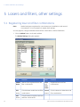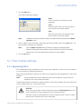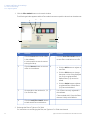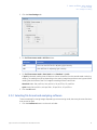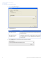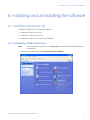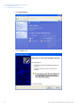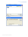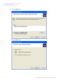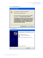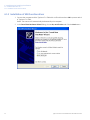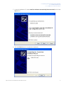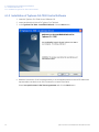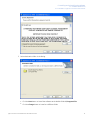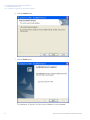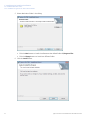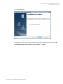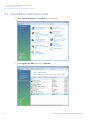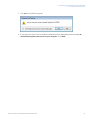
1
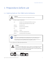
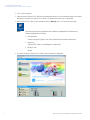
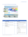
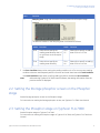
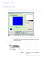
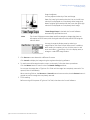
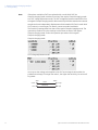
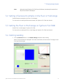
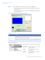
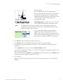
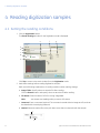
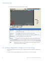
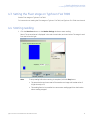
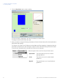
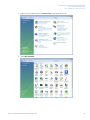
GE Healthcare
Typhoon™ FLA 7000 Control
Software
User Manual
Table of Contents
Table of Contents
1
Preparations before use .................................................................................................................................
1.1 Starting Typhoon FLA 7000 Control Software .......................................................................................................
1.2 Control Software main window ...................................................................................................................................
5
5
7
2
Reading phosphorimaging samples .............................................................................................................
2.1 Setting the reading conditions ......................................................................................................................................
2.2 Setting the Storage phosphor screen on the Phosphor stage .......................................................................
2.3 Setting the Phosphor stage on Typhoon FLA 7000 .............................................................................................
2.4 Starting reading ...................................................................................................................................................................
9
9
11
11
12
3
Reading fluorescent samples ........................................................................................................................
3.1 Setting the reading conditions ......................................................................................................................................
3.2 Setting a fluorescent sample on the Fluor or Multi stage ................................................................................
3.3 Setting the Fluor or Multi stage on Typhoon FLA 7000 .....................................................................................
3.4 Starting reading ...................................................................................................................................................................
15
15
19
19
19
4
Reading digitization samples ........................................................................................................................
4.1 Setting the reading conditions ......................................................................................................................................
4.2 Setting a digitization sample on the Fluor stage ..................................................................................................
4.3 Setting the Fluor stage on Typhoon FLA 7000 ......................................................................................................
4.4 Starting reading ...................................................................................................................................................................
22
22
24
25
25
5
Lasers and filters, other settings ..................................................................................................................
5.1 Registering laser and filter combinations ................................................................................................................
5.2 Filter module settings ........................................................................................................................................................
5.2.1 Registering filters ..............................................................................................................................................................
5.2.2 Saving filter combinations ...........................................................................................................................................
5.2.3 Recalling filter combinations ......................................................................................................................................
5.2.4 Registering a new filter name ....................................................................................................................................
5.2.5 Edit a filter name or remove a filter ..........................................................................................................................
5.3 Other settings .......................................................................................................................................................................
5.3.1 Settings for scanning .......................................................................................................................................................
5.3.2 Selecting file format and analyzing software .......................................................................................................
28
28
29
29
32
33
34
34
34
34
35
6
Installing and uninstalling the software .....................................................................................................
6.1 Installation (Windows XP) ................................................................................................................................................
6.1.1 Installation of USB Control Driver ...............................................................................................................................
6.1.2 Installation of USB Function driver ............................................................................................................................
6.1.3 Installation of Typhoon FLA 7000 Control Software .........................................................................................
6.2 Uninstallation (For Windows XP) ..................................................................................................................................
6.3 Installation (Windows Vista) ...........................................................................................................................................
6.3.1 Installation of USB control driver ................................................................................................................................
6.3.2 Installation of USB function driver ............................................................................................................................
6.3.3 Installation of Typhoon FLA 7000 Control Software ..........................................................................................
6.4 Uninstallation (Windows Vista) .....................................................................................................................................
37
37
37
46
48
51
52
52
60
62
66
Typhoon FLA 7000 Control Software User Manual 28-9607-63 AA
3
Table of Contents
7
4
Troubleshooting ...............................................................................................................................................
7.1 Errors .........................................................................................................................................................................................
7.2 Warnings .................................................................................................................................................................................
68
68
68
Typhoon FLA 7000 Control Software User Manual 28-9607-63 AA
1 Preparations before use
1 Preparations before use
1.1 Starting Typhoon FLA 7000 Control Software
CAUTION
Please note that the GUI screens may change without notice.
Note:
Minimum computer requirements:
OS:
Windows XP™ Professional SP3 (32-bit) or later, or
Windows Vista™ Business SP1 (32-bit) or later
Memory:
More than 1 GB
Processor:
Intel Core 2 Duo processors
HD:
More than 80 GB
USB ports:
USB 2.0
Optical drives:
DVD-ROM or SuperMulti Drive
Monitor:
more than 1280 x 1024 resolution
NOTICE
Do not connect any USB devices other than Typhoon FLA 7000 to the computer in which the
Typhoon FLA 7000 Control Software is installed. Otherwise, it may cause malfunctions.
During reading, do not use any USB devices other than Typhoon FLA 7000 connected to the
computer. If USB devices are used simultaneously, image data may be lost.
1 Turn on Typhoon FLA 7000 and peripheral devices.
CAUTION
Do not insert a Storage phosphor screen in Typhoon FLA 7000 before turning on
the machine. If an imaging plate is detected during the self-diagnosis of the
Typhoon FLA 7000, the sensitivity of the Storage phosphor screen may deteriorate.
The scanned data can then not be guaranteed.
USB
Connection
Typhoon FLA 7000 Control Software User Manual 28-9607-63 AA
5
1 Preparations before use
1.1 Starting Typhoon FLA 7000 Control Software
2 Turn on the computer.
3 Make sure that Typhoon FLA 7000 has completed the warm-up. Only the power lamp on the upper
left panel on the front of Typhoon FLA 7000 is lit up when the warm-up is completed.
4 Start Typhoon FLA 7000 Control Software from the Startup menu, or use the shortcut key.
Note:
After starting the Control Software, the condition is displayed in the Status area.
Status messages are as follows:
• Disconnected:
Cannot recognize Typhoon FLA 7000. Please check connection and power.
• Warm-up:
Typhoon FLA 7000 is in self-diagnosis. Please wait.
• Ready to use:
Ready
5 The main window of Typhoon FLA 7000 Control Software is displayed.
6
Typhoon FLA 7000 Control Software User Manual 28-9607-63 AA
1 Preparations before use
1.2 Control Software main window
1.2 Control Software main window
1
2
3
4
9
5
6
7
8
No.
Name
No.
Name
1
Phosphorimaging
6
Preferences...
Click when reading a Storage phosphor
screen.
2
Fluorescence
Click to set the display menu, file format, or
the Log/ Square Root of image data type.
7
Click when reading fluorescent samples.
3
Digitization
Click when digitizing.
Filter
The loaded filters are displayed.
8
Laser
The conditions of the loaded laser units are
displayed.
In this example, there are four types of laser
units loaded:
• 532 nm laser,
• 473 nm laser,
• 650 nm laser,
• 635 nm laser.
All the laser units are ready for operation
(OK).
Typhoon FLA 7000 Control Software User Manual 28-9607-63 AA
7
1 Preparations before use
1.2 Control Software main window
No.
Name
No.
Name
4
Method
9
Status:Ready
Click to register or erase combinations of
lasers and filters.
5
The status of the FLA 7000 is displayed. When
the status is Ready, The FLA 7000 is ready
for scanning.
Filter Module
Click to change or register the filter.
8
Typhoon FLA 7000 Control Software User Manual 28-9607-63 AA
2 Reading phosphorimaging samples
2 Reading phosphorimaging samples
2.1 Setting the reading conditions
1 Click the Phosphorimaging button.
The Reader Settings window for the Phosphorimaging mode is displayed.
e
f
g
a
b
c
d
h
Click Top to return to the main window from the Phosphorimaging mode.
2 Make these settings before reading Storage phosphor screens.
Explanations for the various settings are found below.
Part
Function
a
Image Folder: Specify where the file is saved after reading by clicking the Browse
button.
b
File Name: Enter a file name to save data of a read image.
Note:
c
You cannot start reading unless you enter a file name.
Comment:
Enter a comment (optional). The comment is saved with the image as a file, and can
be viewed with the analyzing software.
Typhoon FLA 7000 Control Software User Manual 28-9607-63 AA
9
2 Reading phosphorimaging samples
2.1 Setting the reading conditions
Part
Function
d
Laser:/Filter: Before reading begins, make sure that the 650 nm laser is shown and
the IP filter is selected in the Setting field as shown below.
In Phosphorimaging reading, the 650 nm laser and IP filter are selected automatically.
Note:
e
To use the Phosphorimaging mode, the LD 650nm laser must be
loaded, and the IP filter must be set. If these conditions are not fulfilled,
the Reader Settings window for the Phosphorimaging mode cannot
be accessed.
PMT: You may set the voltage to be applied to the photo-multiplier tube (PMT) as an
integral value within the predetermined range. The larger the value is, the higher the
sensitivity.
500V
Value
Small
Low
f
10
Large
Sensitivity
High
Pixel Size: Set the pixel size for reading. Click to select from one of the four types, as
shown on the left. A sample with a smaller pixel size is analyzed more finely.
200
g
1000V
100
50
Short
Reading Time
Small
Image File Size
m 25
Long
Large
Latitude: Specify the dynamic range. The dynamic range that can be detected is
larger with L5 than with L4. If the signals of the sample are in the L4 range, the density
gradation is represented more finely if L4 is selected.
Typhoon FLA 7000 Control Software User Manual 28-9607-63 AA
2 Reading phosphorimaging samples
2.1 Setting the reading conditions
Part
Function
h
Sampling Area: Drag and select the scanning area on the Phosphor stage.
The different modes on the Sampling Area are selected as follows:
Mode
Function
Mode
Function
Grid
Select this to specify the
reading area based on the 2.5
cm grid lines on the Phosphor
stage.
20 x
25
Select this to specify a reading
area of 20 cm x 25 cm.
Free
Select this to specify the
reading area arbitrarily.
20 x
40
Select this to specify a reading
area of 20 cm x 40 cm.
3 Use Save Condition button when saving the reading conditions in a file. You may save reading
conditions that are used frequently with this function and recall them later with Load Condition.
Use Load Condition button when recalling reading conditions saved with Save Condition.
Note:
When starting Typhoon FLA 7000 Control Software, the settings information from the
previous session is displayed.
2.2 Setting the Storage phosphor screen on the Phosphor
stage
Set the Storage phosphor screen on the Phosphor stage.
For instructions on setting the Storage phosphor screen, see Typhoon FLA 7000 User Manual
2.3 Setting the Phosphor stage on Typhoon FLA 7000
Set the Phosphor stage on Typhoon FLA 7000.
For instructions on setting the Phosphor stage on Typhoon FLA 7000, see Typhoon FLA 7000 User
Manual.
Typhoon FLA 7000 Control Software User Manual 28-9607-63 AA
11
2 Reading phosphorimaging samples
2.4 Starting reading
2.4 Starting reading
1 Click the Start Scan button on the Reader Settings window to start reading.
Result: The scanned area is displayed in the real-time window, as shown below. The stage is read
from the left to the right.
Note:
To stop reading before the scanning is completed, click the Stop button.
• The area that has not been read will be saved as an image with a data value of
0 (light intensity of 0)
• The reading function is cancelled. You cannot start reading again from the location
where reading stopped.
2 When you want to change the display parameters of the real-time window, refer to the explanations
below.
Select the type of tone curve from the pull-down menu.
12
Exponential:
The exponential tone curve is used to
adjust gradations.
Linear:
The linear tone curve is used to adjust
gradations.
Sigmoid:
The sigmoid tone curve is used to adjust
gradations.
Typhoon FLA 7000 Control Software User Manual 28-9607-63 AA
2 Reading phosphorimaging samples
2.4 Starting reading
Drag the adjuster.
You may adjust the density of the read image.
Data of a lower light intensity than the line on the left (Low
value) will be displayed as a completely white image, and
data of a higher light intensity than the line on the right (High
value) will be displayed as a completely black image.
If Auto Range Scope is checked, the Control Software
automatically optimizes the tone.
Note:
The Control Software converts data read from samples to images that have an
information of 65536 tones, with 0 being the value for white, and 65535 being the
value for black.
You may change the display area by selecting a
magnification ratio from the pull-down menu. In addition,
after reading is complete, you can click the zoom in and
zoom out button
and then click in the display area, to
enlarge or reduce the magnification.
3 Click Save as to save data with a different file name.
Click Launch to display the image using the registered analyzing software.
4 To read a second Storage phosphor screen continuously, follow the above procedures.
Click the Return button to return to the first Reader Settings window.
Do not open the stage door of Typhoon FLA 7000 until the stage has completely returned. If it is
opened, close it immediately.
When scanning finishes, the Save as and Launch buttons become active, but the Return button is
grayed out until the stage has completely returned.
5 Finish reading.
Before turning off the power of Typhoon FLA 7000, shut down the Control Software.
Typhoon FLA 7000 Control Software User Manual 28-9607-63 AA
13
2 Reading phosphorimaging samples
2.4 Starting reading
Note:
If the photo-multipliers (PMT) are replaced with a multi-alkali PMT, the
Phosphorimaging mode switches from that of the regular Phosphorimaging mode
to a PMT voltage adjustment mode. The PMT voltage adjustment mode differs from
the regular Phosphorimaging mode in that a sensitivity level that matches the scanned
sample can be set independently. Replacement of the standard PMT with a multi-alkali
PMT is done by a serviceman. For details, contact an authorized dealer.
The Sensitivity settings differ from that of the regular Phosphorimaging mode. The
operation procedures for other settings are the same as those of the regular
Phosphorimaging mode. Follow the operation procedures of the regular
Phosphorimaging mode.
Phosphorimaging mode
PMT voltage adjustment mode
You may set the voltage to be applied to the PMT as an integral value within the
predetermined range. The larger the value is, the higher the sensitivity, but noise will
be greater.
500V
Value
Small
Low
14
1000V
Large
Sensitivity
High
Typhoon FLA 7000 Control Software User Manual 28-9607-63 AA
3 Reading fluorescent samples
3 Reading fluorescent samples
3.1 Setting the reading conditions
1 Click the Fluorescence button.
The Reader Settings window for the Fluorescence mode is displayed.
e
f
a
b
c
d
g
Click Top to return to the main window from the Fluorescence mode.
2 Make these settings before reading fluorescent samples.
Refer to the following explanations of reading conditions when making settings.
a Image Folder: Click the Browse button and specify where to save the file after reading.
Note:
When scanning multiple times, the image data are saved in the folder with the
name specified in File Name, which is automatically created in the specified
location.
b File Name: Enter the name of a file for saving image data.
Note:
You cannot start reading unless you enter a file name.
Typhoon FLA 7000 Control Software User Manual 28-9607-63 AA
15
3 Reading fluorescent samples
3.1 Setting the reading conditions
Note:
When the number of scans is between two and four, the laser name and scan
number are automatically added to the specified name.
000- 635- 1
File
Name
Laser
Name
Scan
Number
If reading is set with the 635 nm laser, 473 nm laser, 635 nm laser, and 635 nm
laser, with "test" as the file name, then the following files are created in the "test"
folder.
test-635-1
test-473
test-635-2
test-635-3
c Comment: Enter a comment (optional). The comment is saved with the image as a file, and can
be viewed with the analyzing software.
d Scanning Method and PMT
Scanning can be performed up to four times.
Method and PMT are set for each scanning.
Part
Description
From the pull-down menu, select the Method that corresponds
with the sample. The selected laser and filter combination is
displayed below.
You may set the voltage to be applied to the photo-multiplier
tube (PMT) as an integral value within the predetermined range.
The larger the value is, the higher the sensitivity.
500V
Value
Small
Low
16
1000V
Large
Sensitivity
High
Typhoon FLA 7000 Control Software User Manual 28-9607-63 AA
3 Reading fluorescent samples
3.1 Setting the reading conditions
Part
Description
Click the + button to increase the number of scans, and click
the - button to reduce the number of scans. Up to four scans
can be performed.
e Pixel Size: Set the pixel size for reading. Click to select from one of the four types, as shown on
the left. A sample with a smaller pixel size is analyzed more finely.
200
f
100
50
Short
Reading Time
Small
Image File Size
m 25
Long
Large
Latitude: Specify the dynamic range. The dynamic range that can be detected is larger with L5
than with L4. If the signals of the sample are in the L4 range, the density gradation is represented
more finely if L4 is selected.
g Drag and select the scanning area on the Flour stage.
Item
Function
Grid mode
Select Grid mode to specify the reading area based on the 2.5 cm grid
lines on the Fluor stage.
Free mode
Select Free mode to arbitrarily specify the reading area.
All mode
Select All mode to specify the entire Fluor stage as the reading area.
Reading Time
Displays estimated time until reading finishes.
File size
Displays size of the file. Expressed as file size per test x number of scans.
Typhoon FLA 7000 Control Software User Manual 28-9607-63 AA
17
3 Reading fluorescent samples
3.1 Setting the reading conditions
When you use the Multi stage (optional accessory)
When the gel with the glass and the titer plate sample are read by using the Multi stage and TP
plugin, change Stage type in the pull-down list.
Display of Multi stage
Drag and select the scanning area on the Multi stage.
Display of Multi stage (and TP plugin)
Select the scanning area on the shape of titer plate.
3 Reuse reading conditions: Use the Save Condition button when saving the reading conditions in a
file. You may save reading conditions that are used frequently with this function and recall them
later with the Load Condition button.
18
Typhoon FLA 7000 Control Software User Manual 28-9607-63 AA
3 Reading fluorescent samples
3.1 Setting the reading conditions
Note:
When starting the Typhoon FLA 7000 Control Software, the settings information from
the previous session is displayed.
3.2 Setting a fluorescent sample on the Fluor or Multi stage
Set the fluorescent sample on the Fluor or Multi stage.
For instructions on setting the fluorescent sample, see Typhoon FLA 7000 User Manual.
3.3 Setting the Fluor or Multi stage on Typhoon FLA 7000
Set the Fluor or Multi stage on Typhoon FLA 7000.
For instructions on setting the Fluor or Multi stage, see Typhoon FLA 7000 User Manual.
3.4 Starting reading
1 Click the Start Scan button on the Reader Settings window to start reading.
Result: The scanned area is displayed in the real-time window, as shown below. The stage is read
from the left to the right.
Typhoon FLA 7000 Control Software User Manual 28-9607-63 AA
19
3 Reading fluorescent samples
3.4 Starting reading
Note:
To stop reading before the scanning is completed, click the Stop button.
• The area that has not been read will be saved as an image with a data value of
0 (light intensity of 0)
• The reading function is cancelled. You cannot start reading again from the location
where reading stopped.
2 View information about the scan in the lower part of the
window.
1
2
No.
Funtion
1
Displays the scan results of the 1st, 2nd, 3rd, and 4th scan, starting from the
left. Click on the tabs to switch the display.
2
Displays information related to the contents of the currently displayed scan.
3 When you want to change the display parameters of the real-time window, refer to the explanations
below and make settings.
Select the type of tone curve from the pull-down menu.
20
Exponential:
The exponential tone curve is used
to adjust gradations.
Linear:
The linear tone curve is used to
adjust gradations.
Sigmoid:
The sigmoid tone curve is used to
adjust gradations.
Typhoon FLA 7000 Control Software User Manual 28-9607-63 AA
3 Reading fluorescent samples
3.4 Starting reading
Drag the adjuster.
You may adjust the density of the read image.
Data of a lower light intensity than the line on the left
(Low value) will be displayed as a completely white
image, and data of a higher light intensity than the line
on the right (High value) will be displayed as a
completely black image.
If Auto Range Scope is checked, the Typhoon FLA 7000
Control Software automatically optimizes the tone.
Note:
The Typhoon FLA 7000 Control Software converts data read from samples to
images that have an information of 65536 tones, with 0 being the value for white,
and 65535 being the value for black.
You may change the display area by selecting a
magnification ratio from the pull-down menu. In
addition, after reading is complete, you can click the
zoom in and zoom out button
and then click in the
display area, to enlarge or reduce the magnification.
4 Click Save as to save the data with a different file name.
Click Launch to launch the registered analyzing software to display the image.
5 To read another fluorescent sample continuously, carry out reading by following the above
procedures.
Click the Return button to return to the first Reader Settings window.
Do not open the stage door of Typhoon FLA 7000 until the stage has completely returned. If it is
opened, close it immediately.
When scanning finishes, the Save as.. and Launch buttons become active, but the Return button
is grayed out until the stage has completely returned.
6 Finish reading.
Before turning off the power of Typhoon FLA 7000, shut down the Typhoon FLA 7000 Control
Software.
Typhoon FLA 7000 Control Software User Manual 28-9607-63 AA
21
4 Reading digitization samples
4 Reading digitization samples
4.1 Setting the reading conditions
1 Click the Digitization button.
The Reader Settings window for the Digitization mode is displayed.
e
f
g
a
b
c
d
h
Click Top to return to the main window from the Digitization mode.
2 Make these settings before reading digitization samples.
Refer to the following explanations of reading conditions when making settings.
a Image Folder: Specify where to save the file after reading.
Click the Browse button and specify where to save the file after reading.
b File Name: Enter the name of a file for saving image data.
Note:
You cannot start reading unless you enter a file name.
c Comment: Enter a comment (optional). The comment is saved with the image as a file, and can
be viewed with the analyzing software.
d Method: Select the method from the pull-down menu that corresponds with the sample .
1
2
22
Typhoon FLA 7000 Control Software User Manual 28-9607-63 AA
4 Reading digitization samples
4.1 Setting the reading conditions
No.
Function
1
The Method to be used for reading is displayed.
2
The contents of the laser and filter combination to be used for reading are
displayed.
To use the Digitization mode, the 473 nm laser must be selected and the Y520
filter must be registered, or the SHG 532 nm laser must be selected and the O580
filter must be registered. If these conditions are not fulfilled, the Reader Condition
Settings window for the Digitization mode cannot be accessed.
Note:
e PMT: You may set the voltage to be applied to the photo-multipliers (PMT) as an integral value
within the predetermined range.
f
Pixel Size: Set the pixel size for reading. Click to select from one of the four types, as shown on
the left. A sample with a smaller pixel size is analyzed more finely.
200
100
50
Short
Reading Time
Small
Image File Size
m 25
Long
Large
g Latitude: Specify the dynamic range. The dynamic range that can be detected is larger with L5
than with L4. If the signals of the sample are in the L4 range, the density gradation is represented
more finely if L4 is selected.
Typhoon FLA 7000 Control Software User Manual 28-9607-63 AA
23
4 Reading digitization samples
4.1 Setting the reading conditions
h Drag and select the scanning area on the Flour stage.
Name
Function
Grid mode
Select Grid mode to specify the reading area based on the 2.5 cm grid
lines on the Fluor stage.
Free mode
Select Free mode to arbitrarily specify the reading area.
All mode
Select All mode to specify the entire Fluor stage as the reading area.
Reading Time
Displays estimated time until reading finishes.
File size
Displays size of the file. Expressed as file size per test x number of scans.
Use the Save Condition button to save the reading conditions in a file. You may save reading
conditions that are used frequently with this function and recall them later with Load Condition.
Note:
When starting the Typhoon FLA 7000 Control Software, the settings information
from the previous session is displayed.
4.2 Setting a digitization sample on the Fluor stage
After setting the digitization sample on the Fluor stage, place the fluorescent plate for digitization on
top of it.
For instructions on setting the digitization sample, see Typhoon FLA 7000 User Manual.
24
Typhoon FLA 7000 Control Software User Manual 28-9607-63 AA
4 Reading digitization samples
4.3 Setting the Fluor stage on Typhoon FLA 7000
4.3 Setting the Fluor stage on Typhoon FLA 7000
Set the Fluor stage on Typhoon FLA 7000.
For instructions on setting the Fluor stage on Typhoon FLA 7000, see Typhoon FLA 7000 User Manual.
4.4 Starting reading
1 Click the Start Scan button on the Reader Settings window to start reading.
Result: The scanned area is displayed in the real-time window, as shown below. The stage is read
from the left to the right.
Note:
To stop reading before the scanning is completed, click the Stop button.
• The area that has not been read will be saved as an image with a data value of
0 (light intensity of 0)
• The reading function is cancelled. You cannot start reading again from the location
where reading stopped.
Typhoon FLA 7000 Control Software User Manual 28-9607-63 AA
25
4 Reading digitization samples
4.4 Starting reading
2 Click the Start Scan button to start reading.
The scanned area is displayed in the real-time window, as shown below.
The stage is read from the left to the right.
3 When you want to change the display parameters of the real-time window, refer to the explanations
below and make settings.
The Typhoon FLA 7000 Control Software converts data read from samples to images that have an
information of 65536 tones, with 0 being the value for white, and 65535 being the value for black.
The tones are indicated by the horizontal axis of the tone curve graph.
Select the type of tone curve from the pull-down menu.
26
Exponential:
The exponential tone curve is used to
adjust gradations.
Linear:
The linear tone curve is used to adjust
gradations.
Sigmoid:
The sigmoid tone curve is used to adjust
gradations.
Typhoon FLA 7000 Control Software User Manual 28-9607-63 AA
4 Reading digitization samples
4.4 Starting reading
Drag the adjuster.
You may adjust the density of the read image.
Data that are lighter than the line on the left (Low value) will
be displayed as a completely white image, and data that are
darker than the line on the right (High value) will be displayed
as a completely black image.
If Auto Range Scope is checked, the Typhoon FLA 7000
Control Software automatically corrects the optimal tone.
You may change the display area by selecting a magnification
ratio from the pull-down menu. In addition, after reading is
complete, you can click the zoom in and zoom out button
and then click in the display area, to enlarge or reduce
the magnification.
4 Click Save as to save the data with a different file name.
Click Launch to launch the registered analyzing software to display the image.
5 To read another digitization sample continuously, follow the above procedures.
Click the Return button to return to the first Reader Settings window.
Do not open the stage door of Typhoon FLA 7000 until the stage has completely returned. If it is
opened, close it immediately.
6 When scanning finishes, the Save as.. and Launch buttons become active, but the Return button
is grayed out until the stage has completely returned.
7 Finish reading.
Before turning off the power of Typhoon FLA 7000, shut down the Typhoon FLA 7000 Control
Software.
Typhoon FLA 7000 Control Software User Manual 28-9607-63 AA
27
5 Lasers and filters, other settings
5 Lasers and filters, other settings
5.1 Registering laser and filter combinations
Note:
Method settings are registered by a serviceman upon installation. Under normal
circumstances, it is not necessary to register these settings.
You may register, change, and delete laser and filter combinations, as described below.
1 Click the Method button on the main window.
The Method Settings dialog box appears.
28
Item
Function
Item
Function
Method
Name
Names of the registered laser and
filter combinations
Laser
and
Filter
Name
Registered laser and filter
combinations
Edit
button
Click this button to edit laser and filter
combinations
Cancel
button
Click this button to delete laser and
filter combinations
Add
button
Click this button to register new laser
and filter combinations
Typhoon FLA 7000 Control Software User Manual 28-9607-63 AA
5 Lasers and filters, other settings
5.1 Registering laser and filter combinations
2 Click the Add button.
The following dialog box appears.
Name
Enter a name for the combination to be
registered.
Laser
Select the type of laser. You may also select
lasers that are not actually loaded.
Filter
Select the type of filter. You may also select
lasers that are not actually loaded.
Note:
Combinations of lasers and filters that are not loaded cannot be selected in the Reader
Condition screen.
3 Enter a name for the combination, select the type of laser and filter, and click the OK button. The
laser and filter combination is registered .
Note:
Click the Delete and Edit buttons to delete or change a registered Method.
Methods initially registered as default cannot be deleted or edited. The Methods
marked with [**] are the Methods that initially were set as default.
4 Click the OK button.
5.2 Filter module settings
5.2.1 Registering filters
Filter module settings are registered by a serviceman upon installation. Under normal circumstances,
it is not necessary to register these settings.
After exchanging the filters of Typhoon FLA 7000, you must register the exchanged filters in the Control
Software.
Note:
Newly installed filters must be registered in the Control Software, or they will not be
displayed in the Control Software window.
The following explains the method for registering filters in the Control Software when the [Y520] is set
in filter module position No. 2 (second from last).
CAUTION
When removing the filter module, make sure to press the Filter Module button and
remove it after the window changes to the Filter Settings window.
If the filter module is removed with force, the area where the filter comes in contact
with the photo-multipliers (PMT) will be damaged.
Typhoon FLA 7000 Control Software User Manual 28-9607-63 AA
29
5 Lasers and filters, other settings
5.2 Filter module settings
5.2.1 Registering filters
1 Click the Filter Module button on the main window.
The following window appears and the filter module moves to a position where it can be taken out.
1
2
3
7
4
6
5
No.
Function
No.
Function
1
Click the Insert button to set a filter
in the software.
5
Click the Save Filter Module button
to save filter combinations as a file.
6
• Click the Add button to register a
new filter.
It is also possible to use the mouse
to drag-and-drop.
2
Click the Remove button to remove
a filter in the software.
• Click the Edit button to change
the name or color of the displayed
icon for the registered filter.
Default filters ([**]) cannot be
edited.
• Click the Delete button to delete
a registered filter. Default filters
([**]) cannot be deleted.
3
Corresponds to the numbers (4, 3, 2,
1) on the filter tray.
7
List of filters currently registered in
the software.
Filters marked with [**] are the filters
that are initially set as default.
4
Click the Load Filter Module button
to load saved filter combinations
2 Exchange the filter of Typhoon FLA 7000.
For instructions on exchanging the filter, see Typhoon FLA 7000 User Manual.
30
Typhoon FLA 7000 Control Software User Manual 28-9607-63 AA
5 Lasers and filters, other settings
5.2 Filter module settings
5.2.1 Registering filters
3 Click filter position No. 2.
A red frame appears around the selected filter position.
4 Select [Y520] from the Filter List.
The selected item is highlighted in blue.
Typhoon FLA 7000 Control Software User Manual 28-9607-63 AA
31
5 Lasers and filters, other settings
5.2 Filter module settings
5.2.1 Registering filters
5 Click the Insert button.
It is also possible to drag-and-drop the selected filter to filter position No. 2.
Filter position No. 2 changes to [Y520].
6 Click the OK button to save the selection.
5.2.2 Saving filter combinations
You may save the filter combination that is currently displayed.
Note:
Exchanging the module and saving/recalling filter combinations can be managed more
easily if each user has their own filter module.
1 Click the Filter Module button on the main window.
2 Click the Save Filter Module button.
The following dialog box appears.
32
Typhoon FLA 7000 Control Software User Manual 28-9607-63 AA
5 Lasers and filters, other settings
5.2 Filter module settings
5.2.2 Saving filter combinations
Filter Module Name:
Enter a name for the filter
combination.
3 After entering a name for the filter combination, click the OK button.
The filter combination is saved.
4 Click the OK button.
5.2.3 Recalling filter combinations
You may recall the filter combinations that are currently registered.
1 Click the Filter Module button on the main window.
2 Click the Load Filter Module button.
The Load Filter Module dialog box is displayed.
3 Select the name of the filter combination you want to recall, and click the OK button.
The filter combination is recalled.
4 Click the OK button.
Typhoon FLA 7000 Control Software User Manual 28-9607-63 AA
33
5 Lasers and filters, other settings
5.2 Filter module settings
5.2.4 Registering a new filter name
5.2.4 Registering a new filter name
You may register a filter name.
1 Click the Filter Module button on the main window.
2 Click the Add button.
The following dialog box appears.
Name:
Enter a name for the filter.
Icon:
Select the color of the filter icon to be displayed
in the software.
3 Select the filter name and icon color you want to register, and click the OK button.
The filter is registered.
4 Click the OK button.
5.2.5 Edit a filter name or remove a filter
Registered filter name can be deleted using Delete, while Remove is used to empty a filter position in
the filter module in the software.
To delete or edit the register filter name, select the filter name and click the Delete or Edit button.
Methods initially registered as default cannot be deleted or edited.
Click the Remove button to keep the filter position empty after removing a filter.
5.3 Other settings
These are settings that are carried out when specifying settings for reading samples.
Depending on the reading mode, there may be some functions that cannot be used.
5.3.1 Settings for scanning
1 Click the Preferences button on the main window.
34
Typhoon FLA 7000 Control Software User Manual 28-9607-63 AA
5 Lasers and filters, other settings
5.3 Other settings
5.3.1 Settings for scanning
2 Click the Scan Settings tab.
3 For For fluorescence mode : ND Filter select:
Selection
Function
Off
Does not use ND filter for adjusting light intensity.
On
Uses ND filter for adjusting light intensity.
4 For For fluorescence mode : Scan Mode select Standard or Quick.
If Quick is selected, reading time will become shorter. However, the noise would stand out during
reading. The reading time varies depending on the setting image size and the scanning area. When
reading the whole area of the Fluor stage the reading times are as follows.
Standard Mode: 200 μm/210 s, 100 μm/210 s, 50 μm/330 s, 25 μm/450 s.
Quick Mode: 200 μm/150 s, 100 μm/150 s, 50 μm/210 s, 25 μm/330 s.
5 Click the OK button.
5.3.2 Selecting file format and analyzing software
These are settings for saving images. Depending on the scanning mode, there may be some functions
that cannot be used.
1 Click the Preferences button on the main window.
Typhoon FLA 7000 Control Software User Manual 28-9607-63 AA
35
5 Lasers and filters, other settings
5.3 Other settings
5.3.2 Selecting file format and analyzing software
2 Click the Image File Settings tab.
3 For File Format select:
Selection
Function
Gel Image File (*.gel)
The standard file format is a .gel file which contains square root
encoded pixel data.
Gel Image File (*.gel) +
Tiff Image File (*.tif)
In combination with a .gel file, a read image can also be saved
in TIFF file format. For TIFF files, image data type is always set
to Linear format.
4 Click the Select button, and select the specified analyzing software.
C:\Program Files\GE Healthcare\ImageQuantTL\1d.exe
36
Typhoon FLA 7000 Control Software User Manual 28-9607-63 AA
6 Installing and uninstalling the software
6 Installing and uninstalling the software
6.1 Installation (Windows XP)
Installation is performed in the following sequence.
1 Installation of USB Control driver
2 Installation of USB Function driver
3 Installation of Typhoon FLA 7000 Control Software
6.1.1 Installation of USB Control Driver
Note:
The computer and Typhoon FLA 7000 must not be connected with a USB cable during
the operation.
1 Open the control panel and select Printers and Other Hardware.
Typhoon FLA 7000 Control Software User Manual 28-9607-63 AA
37
6 Installing and uninstalling the software
6.1 Installation (Windows XP)
6.1.1 Installation of USB Control Driver
2 Click Add Hardware.
3 Click the Next button.
38
Typhoon FLA 7000 Control Software User Manual 28-9607-63 AA
6 Installing and uninstalling the software
6.1 Installation (Windows XP)
6.1.1 Installation of USB Control Driver
4 Select Yes, I have already connected the hardware and click the Next button.
5 Select Add a new hardware device and click the Next button.
Typhoon FLA 7000 Control Software User Manual 28-9607-63 AA
39
6 Installing and uninstalling the software
6.1 Installation (Windows XP)
6.1.1 Installation of USB Control Driver
6 Select Install the hardware that I manually select from a list [Advanced] and click the Next button.
7 Select Show All Devices and click the Next button.
40
Typhoon FLA 7000 Control Software User Manual 28-9607-63 AA
6 Installing and uninstalling the software
6.1 Installation (Windows XP)
6.1.1 Installation of USB Control Driver
8 Click the Have Disk button.
9 Insert the Typhoon FLA 7000 Control Software CD and click the Browse button.
Typhoon FLA 7000 Control Software User Manual 28-9607-63 AA
41
6 Installing and uninstalling the software
6.1 Installation (Windows XP)
6.1.1 Installation of USB Control Driver
10 Select to install the driver from the Typhoon FLA 7000 Control Software CD.
11 Open the USB Control folder.
42
Typhoon FLA 7000 Control Software User Manual 28-9607-63 AA
6 Installing and uninstalling the software
6.1 Installation (Windows XP)
6.1.1 Installation of USB Control Driver
12 Select the DevMng.inf file and click the Open button.
13 Click the OK button.
Typhoon FLA 7000 Control Software User Manual 28-9607-63 AA
43
6 Installing and uninstalling the software
6.1 Installation (Windows XP)
6.1.1 Installation of USB Control Driver
14 Click the Next button.
15 Click the Next button.
44
Typhoon FLA 7000 Control Software User Manual 28-9607-63 AA
6 Installing and uninstalling the software
6.1 Installation (Windows XP)
6.1.1 Installation of USB Control Driver
16 Click the Continue Anyway button.
17 Click the Finish button.
Typhoon FLA 7000 Control Software User Manual 28-9607-63 AA
45
6 Installing and uninstalling the software
6.1 Installation (Windows XP)
6.1.2 Installation of USB Function driver
6.1.2 Installation of USB Function driver
1 Connect the computer and the Typhoon FLA 7000 with a USB cable and turn ON the power switch
of Typhoon FLA 7000.
Result: The scanner will automatically be detected by the computer.
2 In the Found New Hardware Wizard dialog, choose No, not this time and click the Next button.
46
Typhoon FLA 7000 Control Software User Manual 28-9607-63 AA
6 Installing and uninstalling the software
6.1 Installation (Windows XP)
6.1.2 Installation of USB Function driver
3 Insert the installation CD, select Install the software automatically (Recommended) and click the
Next button.
4 Click the Finish button to complete the installation.
Typhoon FLA 7000 Control Software User Manual 28-9607-63 AA
47
6 Installing and uninstalling the software
6.1 Installation (Windows XP)
6.1.3 Installation of Typhoon FLA 7000 Control Software
6.1.3 Installation of Typhoon FLA 7000 Control Software
1 Insert the Typhoon FLA 7000 Control Software CD.
2 Locate and double-click the file Typhoon FLA 7000.msi.
3 In the Typhoon FLA 7000 - InstallShield Wizard, click the Next button.
4 Read the license text. If the license agreement is not acceptable please contact a GE Healthcare
representative, see back cover of this manual for contact information.
Select I accept the terms in the license agreement and click the Next button.
48
Typhoon FLA 7000 Control Software User Manual 28-9607-63 AA
6 Installing and uninstalling the software
6.1 Installation (Windows XP)
6.1.3 Installation of Typhoon FLA 7000 Control Software
5 Select destination folder in the dialog:
• Click the Next button to install the software at the default folder C:\Program Files.
• Click the Change button to install to a different folder.
Typhoon FLA 7000 Control Software User Manual 28-9607-63 AA
49
6 Installing and uninstalling the software
6.1 Installation (Windows XP)
6.1.3 Installation of Typhoon FLA 7000 Control Software
6 Click the Install button.
7 Click the Finish button.
The installation of Typhoon FLA 7000 Control Software is now completed.
50
Typhoon FLA 7000 Control Software User Manual 28-9607-63 AA
6 Installing and uninstalling the software
6.2 Uninstallation (For Windows XP)
6.2 Uninstallation (For Windows XP)
1 Open the control panel and select Add or Remove Programs.
2 Select Typhoon FLA 7000 and click the Remove button.
Typhoon FLA 7000 Control Software User Manual 28-9607-63 AA
51
6 Installing and uninstalling the software
6.2 Uninstallation (For Windows XP)
3 Click Yes.
Result: A progress bar is displayed and uninstallation is started.
Note:
Correction files created during calibration, such as shading data are required by the
Typhoon FLA 7000 Control Software. They are not deleted during the uninstallation, and
remain in the Data folder of Typhoon FLA 7000 Control Software folder.
6.3 Installation (Windows Vista)
Installation is performed in the following sequence.
1 Installation of USB Control driver
2 Installation of USB Function driver
3 Installation of Typhoon FLA 7000 Control Software
6.3.1 Installation of USB control driver
52
Note:
The computer and Typhoon FLA 7000 must not be connected with a USB cable during
the operation.
Note:
During software installations, you may be asked to confirm your actions in a dialog with
the text Windows needs your permission to continue. Enter an administrator password,
if prompted, then click Continue to proceed with the installation.
Typhoon FLA 7000 Control Software User Manual 28-9607-63 AA
6 Installing and uninstalling the software
6.3 Installation (Windows Vista)
6.3.1 Installation of USB control driver
1 Open the control panel and click Classic View in the upper left corner.
2 Open Add Hardware.
Typhoon FLA 7000 Control Software User Manual 28-9607-63 AA
53
6 Installing and uninstalling the software
6.3 Installation (Windows Vista)
6.3.1 Installation of USB control driver
3 In the Add Hardware dialog, click the Next button.
4 Select Install the hardware that I manually select from a list (Advanced) and click the Next button.
54
Typhoon FLA 7000 Control Software User Manual 28-9607-63 AA
6 Installing and uninstalling the software
6.3 Installation (Windows Vista)
6.3.1 Installation of USB control driver
5 Select Show All Devices and click the Next button.
6 Click the Have Disk button.
Typhoon FLA 7000 Control Software User Manual 28-9607-63 AA
55
6 Installing and uninstalling the software
6.3 Installation (Windows Vista)
6.3.1 Installation of USB control driver
7 Insert the Typhoon FLA 7000 Control Software CD and click the Browse button.
8 Select to install the driver from the Typhoon FLA 7000 Control Software CD.
56
Typhoon FLA 7000 Control Software User Manual 28-9607-63 AA
6 Installing and uninstalling the software
6.3 Installation (Windows Vista)
6.3.1 Installation of USB control driver
9 Open the USB Control folder.
10 Select the file DevMng and click the Open button.
Typhoon FLA 7000 Control Software User Manual 28-9607-63 AA
57
6 Installing and uninstalling the software
6.3 Installation (Windows Vista)
6.3.1 Installation of USB control driver
11 Click the OK button.
12 Click the Next button.
58
Typhoon FLA 7000 Control Software User Manual 28-9607-63 AA
6 Installing and uninstalling the software
6.3 Installation (Windows Vista)
6.3.1 Installation of USB control driver
13 Click the Next button.
14 Click Install this driver software anyway.
Typhoon FLA 7000 Control Software User Manual 28-9607-63 AA
59
6 Installing and uninstalling the software
6.3 Installation (Windows Vista)
6.3.1 Installation of USB control driver
15 Click the Finish button.
6.3.2 Installation of USB function driver
Note:
During software installations, you may be asked to confirm your actions in a dialog with
the text Windows needs your permission to continue. Enter an administrator password,
if prompted, then click Continue to proceed with the installation.
1 Connect the computer and the Typhoon FLA 7000 with a USB cable and turn ON the power switch
of Typhoon FLA 7000.
Result: The scanner will automatically be detected by the computer and the Plug and Play function
in Windows Vista starts.
60
Typhoon FLA 7000 Control Software User Manual 28-9607-63 AA
6 Installing and uninstalling the software
6.3 Installation (Windows Vista)
6.3.2 Installation of USB function driver
2 In the Found New Hardware dialog, select Locate and install driver software (recommended).
3 Insert the Typhoon FLA 7000 Control Software CD and click the Next button in the Found New
Hardware dialog.
Typhoon FLA 7000 Control Software User Manual 28-9607-63 AA
61
6 Installing and uninstalling the software
6.3 Installation (Windows Vista)
6.3.2 Installation of USB function driver
4 Select Install this driver software anyway.
5 A successful installation message appears. Click the Close button.
6.3.3 Installation of Typhoon FLA 7000 Control Software
1 Insert the Typhoon FLA 7000 Control Software CD.
2 Locate and double-click the file Typhoon FLA 7000.msi.
62
Typhoon FLA 7000 Control Software User Manual 28-9607-63 AA
6 Installing and uninstalling the software
6.3 Installation (Windows Vista)
6.3.3 Installation of Typhoon FLA 7000 Control Software
3 In the Typhoon FLA 7000 - InstallShield Wizard dialog, click the Next button.
4 Read the license text. If the license agreement is not acceptable, please contact a GE Healthcare
representative. See the back cover of this manual for contact information.
Select I accept the terms in the license agreement and click the Next button.
Typhoon FLA 7000 Control Software User Manual 28-9607-63 AA
63
6 Installing and uninstalling the software
6.3 Installation (Windows Vista)
6.3.3 Installation of Typhoon FLA 7000 Control Software
5 Select destination folder in the dialog:
• Click the Next button to install the software at the default folder C:\Program Files.
• Click the Change button to install to a different folder.
6 Click the Install button.
64
Typhoon FLA 7000 Control Software User Manual 28-9607-63 AA
6 Installing and uninstalling the software
6.3 Installation (Windows Vista)
6.3.3 Installation of Typhoon FLA 7000 Control Software
7 Click the Finish button.
The installation of Typhoon FLA 7000 Control Software is now completed.
8 If User Account Control (UAC) is enabled in Windows Vista, a dialog displays the message An
unidentified program wants access to your computer. Click Allow.
Typhoon FLA 7000 Control Software User Manual 28-9607-63 AA
65
6 Installing and uninstalling the software
6.3 Installation (Windows Vista)
6.3.3 Installation of Typhoon FLA 7000 Control Software
6.4 Uninstallation (Windows Vista)
1 Select Uninstall a program underPrograms in Control Panel.
2 Select Typhoon FLA 7000 and then click Uninstall.
66
Typhoon FLA 7000 Control Software User Manual 28-9607-63 AA
6 Installing and uninstalling the software
6.4 Uninstallation (Windows Vista)
3 Click Yes to uninstall the program.
4 If User Account Control (UAC) is enabled in Windows Vista, a dialog displays the message An
unidentified program wants access to your computer. Click Allow.
Typhoon FLA 7000 Control Software User Manual 28-9607-63 AA
67
7 Troubleshooting
7 Troubleshooting
7.1 Errors
An error is the condition in which all of the reading modes of Typhoon FLA 7000 cannot be used.
When an error occurs, the indicator lamps light up and there is a beeping sound.
An error message dialog box is displayed on the Typhoon FLA 7000 Control Software screen displayed
on the computer.
Please contact GE Healthcare and be prepared to state the four-digit Error Code and the eight-digit
number inside the parentheses.
7.2 Warnings
The following are examples of warnings that are displayed as messages in the Typhoon FLA 7000
Control Software window. If a displayed message includes instructions, please follow them.
Message
Meaning and Countermeasure
Filter module has not been
setup.
Meaning:
Push the filter module
button and set up the filter
module.
• A filter module has not been set.
• Click the filter module button, and set a filter module.
Countermeasure:
• Confirm that a filter module is set.
• If not, set a filter module using the filter module button.
The combination of the
lasers and filters could be
inappropriate.
Check the lasers and filters.
Meaning:
• There is a possibility that the laser and filter combination is
inappropriate. Please check the laser and filter.
Countermeasure:
• Confirm the Methods registered. It is possible that the laser and
filter combination is inappropriate.
• Confirm that the filter specified in the Typhoon FLA 7000 Control
Software is actually set.
68
Typhoon FLA 7000 Control Software User Manual 28-9607-63 AA
7 Troubleshooting
7.2 Warnings
Message
Meaning and Countermeasure
Laser error occurred.
Meaning:
Use other lasers.
• A laser error has occurred.
• Use a different laser.
Countermeasure:
• An error has occurred with the laser. Restart the instrument.
• If an error occurs even after restarting the instrument, call a
serviceman.
• It is possible to scan using a different laser.
Failed to retrieve picture
data from PC.
Check the PC setting.
Meaning
• There was a failure in reading the image data from the computer.
• Check the computer environment.
Countermeasure:
• It is possible that the computer's processing ability has degraded.
Check the computer once, when there are no devices connected
to it and no software started.
PMT error occurred.
Meaning:
Use low sensitivity for the
setting.
• An overexposure error has been detected outside of the scanning
area.
• Scan with low sensitivity settings.
Countermeasure:
• Scan with low sensitivity settings.
• Restart the computer.
• If an error occurs even after restarting the instrument, call a
serviceman.
The file name is already
used.
Meaning:
• The file name is already used for another file.
Countermeasure:
• Change the file name to make sure that the scan data is not lost.
Close the SampleSetDoor or
FilterChangeDoor.
Meaning:
Close the sample set door or the filter change door.
Countermeasure: Close the sample set door or the filter change door.
Typhoon FLA 7000 Control Software User Manual 28-9607-63 AA
69
7 Troubleshooting
7.2 Warnings
Note:
If an error message is displayed, a serviceman should take the countermeasures to
resolve the trouble.
Please contact the dealer where you purchased Typhoon FLA 7000, or contact GE
Healthcare.
* For technical inquiry and any question on application related matters, price of the
products, etc., please contact us to the address on the back cover.
70
Typhoon FLA 7000 Control Software User Manual 28-9607-63 AA
For local office contact information, visit
www.gelifesciences.com/contact
GE Healthcare Bio-Sciences AB
Björkgatan 30
751 84 Uppsala
Sweden
www.gelifesciences.com/quantitative_imaging
GE, imagination at work and GE monogram are trademarks of General Electric Company.
Typhoon is a trademark of GE Healthcare companies.
All third party trademarks are the property of their respective owners.
© 2009 General Electric Company – All rights reserved.
First published Oct. 2009
All goods and services are sold subject to the terms and conditions of sale of the company within GE
Healthcare which supplies them. A copy of these terms and conditions is available on request. Contact
your local GE Healthcare representative for the most current information.
GE Healthcare Europe GmbH
Munzinger Strasse 5, D-79111 Freiburg, Germany
GE Healthcare UK Limited
Amersham Place, Little Chalfont, Buckinghamshire, HP7 9NA, UK
GE Healthcare Bio-Sciences Corp.
800 Centennial Avenue, P.O. Box 1327, Piscataway, NJ 08855-1327, USA
GE Healthcare Bio-Sciences KK
Sanken Bldg.3-25-1, Hyakunincho Shinjuku-ku, Tokyo 169-0073, Japan
imagination at work
28-9607-63 AA 09/2009