1
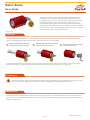
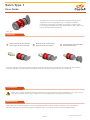
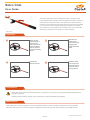
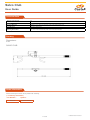
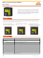
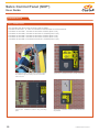
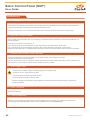
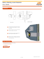
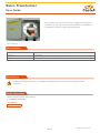
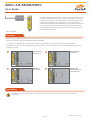
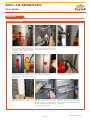
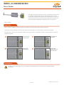
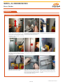
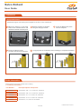
User Manual
www.castell.com
Contents
Section 1- Couplings
Salvo Susie.������������������������������������������������������������������������������������������������������������������������������4
Salvo SGL (Glad Hand Lock) .��������������������������������������������������������������������������������������������������6
Salvo Type 1.����������������������������������������������������������������������������������������������������������������������������8
Salvo Club.�����������������������������������������������������������������������������������������������������������������������������10
Salvo Chock.��������������������������������������������������������������������������������������������������������������������������12
Section 2 - Powered Doors
Salvo SCP+ (Salvo Control Panel Plus).���������������������������������������������������������������������������������15
Salvo Safety Proximity Sensor (for Sectional Doors)..............................................................24
Salvo Safety Limit Switch (for Roller Shutter Doors).�������������������������������������������������������������26
Salvo Transformer.������������������������������������������������������������������������������������������������������������������28
Salvo Power Supply & Beacon (SPSB) .��������������������������������������������������������������������������������29
Section 3 - Manual Doors
SMDL-AIS-SMDB/SDMC (Manual Door Lock) ���������������������������������������������������������������������32
SMDL-AI-SMDB/SDMC (Manual Door Lock) .�����������������������������������������������������������������������35
SADL-SMDB/SDMC (Automatic Door Lock)��������������������������������������������������������������������������38
Section 4 - Loading Bay Barriers
Salvo Bollard.�������������������������������������������������������������������������������������������������������������������������42
Section 5 - Peripherals
Salvo Pedestal.�����������������������������������������������������������������������������������������������������������������������45
Salvo Enclosure.���������������������������������������������������������������������������������������������������������������������46
Salvo Traffic Lights.����������������������������������������������������������������������������������������������������������������47
Section 6 - Safety Critical Information
Safety Critical Information.�����������������������������������������������������������������������������������������������������49
2
U-Salvo-2013-E Issue 1
Section 1
Couplings
U-Salvo-2013-E Issue 1
Salvo Susie
User Guide
The Salvo Susie lock is a key operated mechanical locking device
designed to fit on to all UK trailer, emergency brake line connectors.
It’s purpose is to prevent re-connection of the air brake hose, thereby
immobilising the trailer. When fitted, the Salvo Susie can only be
removed with the permit key. The Salvo Susie has an ergonomically
designed grip. This enables the lock to be fitted and removed efficiently
in wet and cold weather. The grip design provides protection to oil and
grease making it ideal for harsh environments.
Salvo Susie
Operation
The Salvo Susie lock is designed as a part of a safety system to prevent accidental drive aways. The Salvo Susie interlock
ensures the vehicle air line is disconnected before the loading bay door can be opened.
1
Disconnect the airline from the
trailer Susie air line connector.
2
Slide the Salvo Susie lock over the
exposed air line connector.
3
Rotate the key anti-clockwise
and remove the key.
To remove the Susie lock from the trailer, insert and rotate the key clock-wise. Pull the lock off the Susie air line connector.
When the operation is complete the unit should be returned to either the storage enclosure or to the issuer.
Precautions
Salvo Susie is heavy. During the course of normal use, it may become dirty, greasy and slippery. If you drop it on your
foot, you may sustain serious injury. Handle with care. Wear appropriate personal protective clothing.
Maintenance
A lubrication point is provided at the opposite end of the key entry aperture. The recommended lubricant is Armna G4789 or
equivalent. The recommended lubrication interval is 6-12 months as required. Keeping the Salvo Susie lock clean will ensure
long and reliable service.
4 of 51
U-Salvo-2013-E Issue 1
Salvo Susie
User Guide
Technical Data
Working Temperature
Min -25ºC (ice free) Max. +55 ºC
Weight
1,0 kg
Material
Stainless steel lock complete with TPE (Thermoplastic Elastomer) sleeve
Standards
(UK) BS AU138b.C type coupling
Drawing
Dimensions:
in mm
SALVO SUSIE
Order Information
Please advise part number, symbol and dog tag when ordering.
(** mandatory information)
Part Number**
005959
Symbol**
please advise
Dog Tag**
please advise
5 of 51
U-Salvo-2013-E Issue 1
Salvo SGL
User Guide
The Salvo Glad Hand Lock (SGL) is a key operated mechanical locking
device designed to fit on to all European and US trailer, emergency
brake line connectors. Its purpose is to prevent re-connection of the air
brake hose, thereby immobilising the trailer. When fitted, the SGL can
only be removed with the permit key.
Salvo SGL
Operation
1
Disconnect the
airline from the
trailer connector,
then engage the
centre peg of the
SGL on to the air
line connector on
the trailer.
2
Rotate SGL
downwards.
3
Slide the SGL lock
portion towards
the air line
connector.
4
Only when the
Salvo SGL is on
the connecter
can the key be
rotated anticlockwise and
removed.
Removal of the SGL lock is the reverse of the above procedure.
When operation is complete, please return to its normal storage location or issuer.
Precautions
Salvo SGL is heavy. During the course of normal use, it may become dirty, greasy and slippery. If you drop it on your foot,
you may sustain serious injury. Handle with care. Wear appropriate personal protective clothing.
Maintenance
A lubrication point is provided adjacent to the key entry aperture and trigger mechanism. The recommended lubricant is Armna
G4789 or equivalent. The recommended lubrication interval is 6-12 months as required. Keeping the Salvo SGL clean will ensure long and reliable service.
6 of 51
U-Salvo-2013-E Issue 1
Salvo SGL
User Guide
Technical Data
Working Temperature
Min -25ºC (ice free) Max. +55 ºC
Weight
2,0 kg
Housing Material
Light alloy / Stainless steel
Lock Material
Stainless Steel
Standards
Conforms with;
(EU) ISO 1728-1980 Palm Type Coupling
(USA) SAE J318 Glad Hand Connector
Drawing
Dimensions:
in mm
SALVO SGL
Order Information
Please advise part number, symbol and dog tag when ordering.
(** mandatory information)
Part Number**
006504
Symbol**
please advise
Dog Tag**
please advise
7 of 51
U-Salvo-2013-E Issue 1
Salvo Type 1
User Guide
The Salvo Type 1 lock is a key operated mechanical locking device
designed to fit on to all Australian Type 1, emergency brake line
connectors. Its purpose is to prevent re-connection of the air brake
hose, thereby immobilising the trailer. When fitted, the Salvo Type 1 can
only be removed with the permit key.
Salvo Type 1
Operation
1
Disconnect the air line from the
Trailer Type1 air line connector.
2
Slide the Type1 lock over the
exposed air line connector.
3
Rotate the key anti-clockwise
and remove the key.
To remove the Type1 lock from the trailer, insert and rotate the key clock-wise. Pull the lock off the Type1 air line connector.
When the operation is complete the unit should be returned to either the storage enclosure or to the issuer.
Precautions
Salvo Type 1 is heavy. During the course of normal use, it may become dirty, greasy and slippery. If you drop it on your
foot, you may sustain serious injury. Handle with care. Wear appropriate personal protective clothing.
Maintenance
Apply lubrication to the inner plungers. The recommended lubricant is Armna G4789 or equivalent. The recommended
lubrication interval is 6-12 months as required. Keeping the Type 1 lock clean will ensure long and reliable service.
8 of 51
U-Salvo-2013-E Issue 1
Salvo Type 1
User Guide
Technical Data
Working Temperature
Min -25ºC (ice free) Max. +55 ºC
Weight
0,5 kg
Housing Material
Stainless steel
Lock Material
Stainless Steel
Standards
Conforms with; AS4945-2000
Drawing
Dimensions:
in mm
SALVO TYPE 1
Order Information
Please advise part number, symbol and dog tag when ordering.
(** mandatory information)
Part Number**
006505
Symbol**
please advise
Dog Tag**
please advise
9 of 51
U-Salvo-2013-E Issue 1
Salvo Club
User Guide
The Salvo Club helps ensure loading dock safety. The Salvo Club
brings added safety to loading dock procedures by locking a vehicle’s
steering wheel. The Salvo Club can be attached to vehicle steering
wheels of varying sizes and will remain locked in place once the Castell
key is removed. When loading/unloading procedures are complete,
the Castell key may be replaced, and the Salvo Club can be removed
allowing the vehicle driver to depart from the loading bay.
Salvo Club
Operation
1
Begin by fully
closing the two
halves of the
Salvo Club. Then
place the Salvo
Club in position
over the steering
wheel.
2
Slide the two
halves of the
Salvo Club apart,
engaging the
hooks inside the
wheel.
3
Rotate and
remove the key.
4
The Salvo Club
is now locked in
place restricting
rotations of the
steering wheel.
Precautions
Salvo Club will not prevent a vehicle drive-away. It’s purpose is to provide a warning that loading/unloading activity
may still be ongoing.
Handle with Care. Beware of pinch points where the two halves slide/telescope together.
Maintenance
Apply lubrication to the inner plungers. The recommended lubricant is Armna G4789 or equivalent. The recommended
lubrication interval is 6-12 months as required. Keeping the Salvo Club lock clean will ensure long and reliable service.
10 of 51
U-Salvo-2013-E Issue 1
Salvo Club
User Guide
Technical Data
Working Temperature
NA
Weight
1,5kg
Housing Material
Steel/Cro-moly Steel Construction with heat treated steel hook
Lock Material
Stainless Steel/Brass
Steering Wheel Size
Min. 22cm Internal Diameter; Max. 48cm Internal Diameter
Drawing
Dimensions:
in mm
SALVO CLUB
Order Information
Please advise part number and symbol when ordering.
(** mandatory information)
Part Number**
006476
Symbol**
please advise
11 of 51
U-Salvo-2013-E Issue 1
Salvo Chock
User Guide
Salvo Chock is a device designed to immobilise nonarticulated goods
vehicles whilst they are being loaded and unloaded. When used in
conjunction with other Salvo products, it can prevent inadvertent or
unauthorised drive-aways. It is designed to be deployed on the drivers
side front wheel of the vehicle. Salvo Chock introduces discipline into
the chocking procedure by interlocking the chock and the loading bay.
If the chock is not correctly fitted, the bay door cannot be opened. Like
all of the existing products in the Salvo range, Salvo Chock relies on
Castell’s time-proven trapped-key technology
Salvo Chock
Before Use
1
When the chock is received, it will
be configured for transit. To make
the Chock ready for use, the Lock
Support Arm must be secured in
the operational position.
The Lock Support Arm must be
raised to the vertical position and
the Securing Plates (A) fitted to
prevent any movement of the arm.
The Retention Sleeve (B) should be
slid into position around the joint in
the spigot.
2
To complete the assembly the cover
should be fitted with the fixings
provided in 6 positions. The Chock
is then ready for use.
3
A
A
B
Operation
The Salvo Chock is designed as a part of a safety system to prevent accidental drive aways. The Salvo Chock ensures the
vehicle is locked in position before the loading bay door can be opened
1
Salvo Chock assembly is fitted
loosely around drivers-side front
wheel. Rotate the catch anticlockwise to the ‘up’ position, as
shown.
2
Press the pedal until the two chocks
contact the tyre. Continue until lock
springs into place.
3
Remove the untrapped key. The
chock is now secured in place.
Precautions
Salvo Chock is designed to fit any size or type of rigid vehicle from 3 to 26 tonnes with tyre outside diameter from 27.5
to 42 inches (700 to 1070 mm). To prevent the risk of manual handling injury, only move the chock around using the
mobility handle (see photos under Operating Instructions).
Handle with Care. Beware of pinch points where the two halves slide/telescope together.
12 of 51
U-Salvo-2013-E Issue 1
Salvo Chock
User Guide
Maintenance
Periodic visual checks should be carried out by the site manager / safety officer. Do not lubricate lock barrel with oil or grease,
use CK Dry Powder Graphite if necessary.
The recommended grease to lubricate sliding parts is Armna G4789 or equivalent.
Technical Data
Material
Powder coated carbon steel and aluminium
Weight
26kg
Colour
Safety yellow/graphite grey
Drawing
Dimensions:
in mm
SALVO CHOCK
Order Information
Please advise part number and symbol when ordering.
(** mandatory information)
Part Number**
007058
Symbol**
please advise
13 of 51
U-Salvo-2013-E Issue 1
Section 2
Powered Doors
U-Salvo-2013-E Issue 1
Salvo Control Panel (SCP+)
User Guide
The Salvo Control Panel Plus (SCP+) is the main interface between
the Salvo couplings and associated bay door controls. The SCP+
comprises of a wall mounted panel with easy to use Castell
interlock key switch to allow operation of the bay. There is also
panel indication of status and operation. Installation is via plug in
terminals on the internally mounted PCB.
SCP+
Operation
2
The Salvo Control Panel is designed as part of a safety system to prevent accidental drive aways. The Salvo Control Panel
ensures that the loading bay door cannot be opened before the vehicle airline is disconnected via the Salvo Susie coupling
and the key has been transferred from the coupling to the SCP+.
1
SCP+ with bay controls
isolated, ready to receive key.
2
Insert key and turn clockwise.
3
SCP+ with bay controls
energised, ready to open door
and deploy dock leveller.
Specifications
Temperature (Operating)
Min: -25°C, Max: +55°C
Size
300mm(H) x 220mm(W) x 157mm(D) (172mm with Mounting)
Mounting Hole
160mm(H) x 140mm(W) (Mounting Plate) – M8 Fixings
260mm(H) x 160mm(W) (Enclosure) – M8 Fixings
Material
Enclosure – Mild Steel to BS 1449 HR4
Lock Portion – Stainless Steel 304/316
Weight
5.5 kg
Cable Entry Size
M20 x 2
Switch Approvals
IEC947-1.3 IEC947-5 BS EN60947 VDE 0660
UL Listed
TBA
Ingress Protection
IP55 Enclosure
Switch Rating
Continuous, unattended, remote
Power Supply Required
24VDC
Max Power Consumption
20VA / 20W
Power Frequency
50/60Hz
Relay Specification
Max switching voltage 240VAC 6A
Max switching current 6A
15
U-Salvo-2013-E Issue 1
Salvo Control Panel (SCP+)
User Guide
Component Inputs
•
•
•
SPSB (Salvo Power Supply + Beacon)
SADL (Salvo Automatic Door Lock)
SBDS (Salvo Bay Door Sensor)
Component Outputs
•
•
•
•
Traffic Light
Door Control
Dock Leveller Control
Amber Beacon
Precautions
Lockout/ Tagout:
Before installing and using your SCP+ unit, a proper lockout/ tagout procedure should be developed for
this unit and related energy sources.
Training:
Only those trained in the proper use of this equipment should be allowed to install, use and maintain it.
Installation:
Proper installation will ensure safe operation and long life of this product.
Never use this product for anything other than its intended purpose.
It is recommended to route cabling via the cable gland access provided at the base of the unit. Remove
knock-outs and fit cable glands provided.
Always make connections to this device in accordance with instructions set forth in this manual and any
applicable electrical codes for your area.
A lockable, local disconnect is recommended to properly isolate this unit.
Constantly be aware of vehicle traffic on or near the loading bays.
ESD electrostatic discharge: circuit boards are vulnerable to damage by electrostatic discharge. Before
handling any boards ensure you dissipate your body’s charge.
Operation/ Maintenance:
WARNING – Disconnect Electrical Supply Before Opening Unit.
Never operate this unit with the access door open.
Never place any body parts near exposed electrical components.
Avoid poking/ prodding into unit with tools that can conduct electrical current.
Never force the electrical contacts or key solenoid to manually operate this unit.
Failure to follow this instruction could void the manufacturer’s warranty
Preinstallation Check
When preparing to wire multiple devices together for a “system” configuration, it is best to ensure the correct
operation of each device independently before starting, to help reduce troubleshooting time later in the event of
discrepancy.
Prior to installation, when applying equipment on a new supply circuit, always ensure the correct line voltage
exists and is stable. Remember to shut the power off, after this is checked and before performing any wiring of
the system.
16
U-Salvo-2013-E Issue 1
Salvo Control Panel (SCP+)
User Guide
Installation 1/4
Steps for installing the SCP+
Step 1: Specify location of SADL (inside / outside)
Step 2: Mount SCP+
Step 3: Install multi-core cable
Step 4(1): Install Traffic Lights
Step 4(2): Install SPSB
Step 5(1): Install SADL
Step 5(2): Connect Door Close Limit Interface
Step 6: Connect Auto Door Control Interface
Step 7: Connect Dock Leveller Control Interface.
Step 8: Connect power (24VDC)
1 - Specify Location of SCP+
Before carrying out installation it is extremely important to determine the location of the SCP+.
This would depend on the specific site requirement.
The options being:
•
•
•
Mounted inside the Warehouse where the warehouse staff controls the Salvo coupling.
Mounted Outside the Warehouse where the shunters/drivers control the Salvo coupling
If in any doubt contact the site project manager or the Castell Product Manager.
2 - Mount SCP+
Depending on site conditions, Ideally the SCP+ should be mounted 1.5m above floor level. If mounted
outside the building, it should be mounted beneath the traffic lights.
If mounted inside the building it should be located adjacent to the dock controls.
3 - Install Multi-core Cable
Consideration should be taken on how the cables are going to run to the various peripherals.
An assessment of site conditions needs to be taken to determine the type of cable used. Armoured cable
is suggested for areas of low level of protection against damage by vehicles. CY or SY cable to be used
where there is a good level of protection.
The more peripherals and interface connections need, the more cores are required. Consult the wiring
diagram to determine the number of cores needed. It is suggested the power cabling is run separately
where practicable.
Care should be taken to route and secure all wiring to the Control PCB to avoid interference with the
enclosure locking mechanism.
17
U-Salvo-2013-E Issue 1
Salvo Control Panel (SCP+)
User Guide
Installation 2/4
4 (1) - Install traffic Lights
Our standard 24VDC traffic lights are to be used (re SETL).
Connect to Connector 8 Term 7,8,9,10.
9: connect to +ve terminal of red traffic light.
7: connect to +ve terminal of green traffic light.
10 & 8: connect to -ve terminal of both red and green traffic light.
4 (2) - Install SPSB
Mounting Holes:
90mm(H) x 94mm(W) (SPSB) – M5 Fixings
Connections:
Connector 1, Terminals 1, 2 & 3 (SCP+)
1: Connect to +V terminal of PSU
2: Connect to –V terminal of PSU
3: Connect to Earth terminal of PSU
Connector 8, Terminals 5 & 6 (SCP+)
5: Connect to + terminal of Beacon connector block
6: Connect to – terminal of Beacon connector block
18
U-Salvo-2013-E Issue 1
Salvo Control Panel (SCP+)
User Guide
Installation 3/4
5(1) - Install SADL
Our standard 24V door locks are to be used (re SADL).
Connect to terminal 1, 2, 3 & 4 of Connector 2 and terminal 10 of Connector 8.
Connector 2: terminal 1 connect to terminal 2 of SADL (Door Lock)
Connector 2: terminal 2 connect to terminal 14 of SADL (Door Lock)
Connector 2: terminal 3 connect to terminal 4 of SADL (Door Lock)
Connector 8: terminal 4 connect to terminal 3 of SADL (Door Lock)
Connector 8: terminal 10 connect to terminal 1 of SADL (Door Lock)
4 (2) - Install SPSB
19
If locating the SCP+ outside, find a suitable route for
the cable through the building wall, and drill cable
hole as shown.
Typical SCP+ installation location outside warehouse.
Typical SCP+ installation location using mounting
plate.
Typical SCP+ installation location outside warehouse
on pedestal.
U-Salvo-2013-E Issue 1
Salvo Control Panel (SCP+)
User Guide
Installation 4/4
5(2) - Connect Door Close Limit Interface
In the case of an automatic door there is not a requirement for the SADL however there is a requirement for
a signal from the door control panel to indicate the bottom limit.
Connector 2 terminal 1 & 2: connected to bottom limit volt free contacts of the Door control panel.
6 - Auto Door Control Interface
It is the case of an automatic door it is necessary to prevent opening of the door when the Castell Key is in
the free position.
Connect to Connector 2 terminal 7 & 8:
The 7 & 8 terminals to be connected in series with the Door up push button wiring. OR:
The 7 & 8 terminals to be connected across the door inhibit terminal of the Door control panel.
Please note that the SCP+ is a failsafe device therefore if there is a failure then the door cannot be opened.
7 - Connect Dock Leveller Control Interface
It may be necessary to prevent activation of the dock leveler when the door is closed.
Connect to terminal 5 & 6 Connector 2.
The 9 & 10 terminals to be connected in series with the Dock leveler raise push button wiring. Please note
that if there is a power failure, then the dock leveller cannot be raised.
8 - Power Supply Input
Connect 230/110VAC supply to SPSB (supply to be fused at 3A)
Connect Live to L (AC) terminal of PSU
Connect Neutral to N (AC) terminal of PSU
Connect Earth to Earth terminal of PSU
Means of Isolation should be located adjacent to the device and should be clearly marked and easily accessible.
9 - Check Functions
Check all Functions
10 - Fuse Replacement
The SCP+ internal fuse is located above the PCB, adjacent to connector TB4, marked “F/Panel Fuse”
Fuse Rating; 3Amp GSL003 Ø5 x 20mm Time-Lag Glass Tube Fuse (RS668-6007)
20
U-Salvo-2013-E Issue 1
Salvo Control Panel (SCP+)
User Guide
Function
Function
Condition
Key Free
Door de-activated
SADL de-energized
Traffic light green
Orange beacon OFF
Dock leveler de-activated
Vehicle restraint de-activated
SCP+ lights (Green if ext, Red if int)
Key Trapped, Door Closed
Door activated but not yet opened
SADL energized but not yet opened
Traffic light green
Orange beacon ON
Dock leveler de-activated
Vehicle restraint activated
SCP+ lights (Green if ext, Red if int)
Key Trapped, Door Open
Door activated and opened
SADL energized and unbolted
Traffic light red
Orange beacon ON
Dock leveler activated
Vehicle restraint activated
SCP+ lights (Red if ext, Green if int)
Wiring
Connect ID
Description
24VDC
24VDC power connections Connector 1 Term 1 & 2
Power Rating
20w
Connect ID
Description
SADL/Door Closed
Solenoid controlled door lock or the door closed contact in the door control panel.
Connect ID
Description
Auto Door
N/O contacts to interlock with the door.
Cable Size
1.5mm²
Cable Size
Power Rating
6A
1.5mm²
Cable Size
1.5mm²
Dock Leveller
N/O contacts to interlock with the Dock leveller.
6A
1.5mm²
Traffic Light
Change over contacts to control the traffic lights (24VDC).
6A
1.5mm²
Beacon
N/O contacts to control beacon (24VDC).
6A
1.5mm²
Aux 1
Change over contacts to control other peripherals.
6A
1.5mm²
21
U-Salvo-2013-E Issue 1
Salvo Control Panel (SCP+)
User Guide
Wiring Diagram
22
U-Salvo-2013-E Issue 1
Salvo Control Panel (SCP+)
User Guide
Order Information
Please advise part number and symbol when ordering.
(** mandatory information)
Part Number**
007007
23
Symbol**
please advise
U-Salvo-2013-E Issue 1
Salvo Safety Proximity Sensor
User Guide
The Salvo Safety Proximity Sensor is designed for use with Roller
Shutter Doors, where mechanical Roller Switches cannot be used. It
should be mounted in accordance with these instructions, as close to
the door frame as possible, to prevent accidental damage.
Salvo Safety Limit Switch
Specifications
Proximity Switch
Contact Form/Style
Normally Open
Switching Capacity (Resistive)
120 W/VA Max
Switching Voltage
1500 VAC Max
Switching Current
3.0 A. Max
Carry Current
5.0 A. Max
Breakdown Voltage
3000 VDC Min
Contact Resistance
80 mOhms Max
Switching Distance
15mm Min
Operating Temperature Range
-20°C / +85°C
Storage Temperature
-25°C / +90°C
Case Material
Brass (Nickel Plated)
Cable
2 x 0.5mm² PVC covered Black,
insulated Brown / Blue.
Metal Threaded Magnet
Switching Distance
Normally Open
Operating Temperature
-20°C / +85°C
Storage Temperature
-25°C / +85°C
Case Material
Brass (Nickel Plated)
Precautions
Installation should be carried out by a competent and qualified person who has read and understood these instructions.
Do not use this product as a safety or emergency stop device, or in any other application where failure of the product
could result in personal injury. Handle with Care. Beware of Pinch points where the two halves align.
Castell Safety recommends that this switch is wired in series with the door down limit switch. Where this is not possible
two switches should be used (see Installation Wiring Diagram – IMS08992).
Maintenance
From time to time, check that all fixing screws remain tight.
24 of 51
U-Salvo-2013-E Issue 1
Salvo Safety Proximity Sensor
User Guide
Installation
1
The magnet should be mounted low
enough on the door to ensure it does not
reach the point where the door begins to
be rolled, when the door is fully opened.
2
Align the Switch bracket with the Magnet,
mark and drill holes and fix to the frame.
3
Ensure the Switch and Magnet align when
the door is fully closed.
4
Adjust the Switch and Magnet to meet the
acceptable operating distance.
Order Information
Please advise part number when ordering.
(** mandatory information)
Part Number**
007050
25 of 51
U-Salvo-2013-E Issue 1
Salvo Safety Limit Switch
User Guide
The Salvo Safety Limit Switch comprises a mechanical roller switch
and bracket set. It is mounted so that the roller is actuated by the
opening and closing of the loading bay door. It should be mounted in
accordance with these instructions, in a raised position to prevent
accidental damage.
Salvo Safety Limit Switch
Specifications
Product Type
Miniature Safety Limit Switch
Actuator
Side Rotary
Lever Style
Roller Adjustable
Circuitry
1NC 1NO DPST Snap Action
Ampere Rating
10 A (Thermal)
Supply Voltage
240VAC / 250VDC
Housing Material
Plastic
Termination Type
M20
Housing Type
EN 50047
Sealing
IP67 (EN60947-5-1
Approvals
UL, CSA, CE, CCC, TUV
Mechanical Life
15 Million Cycles
Operating Temperature Range
-30°C to 70°C (-22°F to 158°F)
Agency Approvals and Standards
EN60947-5-1, UL508, CSA C22.2 No14, GB14048.5
Precautions
Installation should be carried out by a competent and qualified person who has read and understood these instructions.
Do not use this product as a safety or emergency stop device, or in any other application where failure of the product
could result in personal injury. Handle with Care. Beware of Pinch points where the two halves slide/telescope together.
Castell Safety recommends that this switch is wired in series with the door down limit switch (see Installation Wiring
Diagram – IMS08992).
Maintenance
From time to time, check that all fixing screws remain tight.
26 of 51
U-Salvo-2013-E Issue 1
Salvo Safety Limit Switch
User Guide
Installation
Side Elevation
Plan View
1
The limit switch mounting bracket should
be positioned approximately 3m above
floor height.
2
Align the bracket on the bay door rail and
mark the position of the holes.
3
Drill the holes, and secure the bracket in
place using the fixings provided.
4
Position the door bracket to ensure that
the switch roller is actuated when the
door is fully closed.
Order Information
Please advise part number when ordering.
(** mandatory information)
Part Number**
005606
27 of 51
U-Salvo-2013-E Issue 1
Salvo Transformer
User Guide
Salvo Transformer is used to convert power supplies of 415VAC down
to 230VAC. It is only required on sites where 230VAC is not available. It
is supplied as mounted in a polycarbonate enclosure
Salvo Transformer
Specifications
Enclosure
Polycarbonate, 180mm (h) x 182mm (w) x 111mm (d)
Cable Entry
2 x M20 Glands
Transformer
63VA Transformer Input (0-230V - 400V) Output (2 x 0-115V)
Precautions
Installation should be carried out by a competent and qualified person who has read and understood these
instructions.
Order Information
Please advise part number when ordering.
(** mandatory information)
Part Number**
007264
28 of 51
U-Salvo-2013-E Issue 1
Salvo Power Supply & Beacon (SPSB)
User Guide
The Salvo Power Supply converts 110/240V to 24VDC to power
the SCP+, providing
a safer power level at the user interface. The
SPSB is mounted to the interior wall of the warehouse, adjacent
to the Loading Bay and is combined with an Amber Beacon to
provide notification that the Loading Bay has been activated and it
is safe to open the bay door and commence loading or unloading.
Salvo Power Supply & Beacon
Specifications
Power Supply
Input
Voltage
100~240VAC (88V ~ 264VAC – Full Range)
Frequency
47 - 63Hz
Current
<2A@115V and 1.2A@230V AC input, full load
Inrush Current
<40A@230VAC input, Cold Start at 25°C ambient
Leakage Current
<2.0mA@240VAC input
Output
Voltage
24V
Rated Load
0A
Range Load
3.2A
Output Tolerance
+/- 1%
Line Regulation
+/-0.5%
Load Regulation
+/-0.5%
Ripple Noise MAX
120mV
Efficiency (Typ)
85%
Power
76.8W
29
U-Salvo-2013-E Issue 1
Salvo Power Supply & Beacon (SPSB)
User Guide
Specifications
Enclosure
Material
RAL 7035 Grey Polycarbonate – IEC 60695-1-2
Dimensions
205mm(W) 220mm(H) 140mm(D)
Mounting Details
94mm(W) 90mm(H) – M5
Operating Temperature
-25°C to +115°C
Shock Resistance
20 Joules (IK10)
Ingress Protection
IP65
Beacon
Material
White Polycarbonate
Dimensions
Ø85mm x 81mm(H)
Voltage
11/35VDC
Current
50mA
Operating Temperature
-20°C to +70°C
Ingress Protection
IP65
Cable Entry Size
M20 x 2
Precautions
WARNING – Disconnect Electrical Supply Before Opening Unit
Means of Isolation should be located adjacent to the device and should be clearly marked and easily
accessible.
Installation of this equipment, other than for its specified use, may impair the operation and safety integrity
of this product.
Installation should be carried out by a competent and qualified person who has read and understood
these instructions. Any electrical installation must comply with standard “BS7671 – Requirements for
Electrical Installations”, commonly referred to as the IEE Wiring Regulations, or any particular regulations
and practices, specified by the local electricity supply company at the time of installation. Installation
must be carried out by competent personnel qualified to IEE 17th Edition or any equivalent regulations in
force at the time of installation.
Order Information
Please advise correct part number when ordering.
(** mandatory information)
Part Number**
007008
30
U-Salvo-2013-E Issue 1
Section 3
Manual Doors
U-Salvo-2013-E Issue 1
SMDL-AIS-SMDB/SMDC
User Guide
The SMDL-AIS (Salvo Manual Door Lock) Is a mechanical interlock used
to positively bolt loading bay doors in the closed position. The switch
contacts can be used for controlling power to the dock leveller or other
ancillary electrical devises e.g. traffic lights. The unit incorporates a
locking bolt which passes through the door running rail and into the lock
body. Only when the key is inserted and turned, can the locking bolt
be disengaged, allowing the door to be opened. The turning of the key
closes the switch contacts.
SMDL-AIS-SMDB
Operation
When correctly installed, the loading bay door is locked in the down position and the key is removed. With the key removed,
the switch contacts are open and the dock leveller is disabled.
To operate, first insert the key and rotate clock-wise. The locking bolt can now be rotated on its axis and released.
The loading bay door can now be opened. With the door open, the key is retained in the lock. The dock leveller can now be
operated as normal.
1
Insert the key
into the lock.
2
Rotate the key
clockwise.
3
Rotate the
locking bolt.
4
Release the
locking bolt and
open the door.
Precautions
Installation should be carried out by a competent and qualified person who has read and understood these
instructions.
32 of 51
U-Salvo-2013-E Issue 1
SMDL-AIS-SMDB/SDMC
User Guide
Installation
Fixing Instructions
4 (2) - Install SPSB
Step 01: First ensure the door is fully
closed. Determine the position of the
locking bolt to ensure that either parts
do not clash with existing door fixings.
Suggested height between 1.5m and
2m from floor level.
Step 02: Mark the position of the bolt Step 03: Drill the clearence hole in the
clearance hole on the inside of the door running guide using a 25mm tank cutter.
running guide. Check that the lock and
bolt do not clash with bay controls.
Step 04: Determine the position of the
lock body, ensuring that the bolt entry
hole aligns with the already secured
locking bolt.
Step 05: Use the hole in the door Step 06: Mark and drill the positions of
running guide to align the lock.
the mounting bracket holes.
Step 07: Fix the lock and bracket in Step 08: With the door fully closed,
place with the screws provided.
engage the bolt into the lock body.,
through the previously drilled hole in the
door running guide. Mark the positions
of the fixing holes in the door.
33 of 51
Step 09: Drill and pop-rivet two
positions. Check that the bolt rotates
freely, then drill remaining holes and pop
rivet in place.
U-Salvo-2013-E Issue 1
SMDL-AIS-SMDB/SDMC
User Guide
Specifications
Weight
1,1 kg
Bolt Material
Stainless steel
Housing Material
Stainless Steel
Lock Material
Stainless Steel
Rating
10A
Ingress Protection
IP65
Termination
PG11
Approvals
VDE, UL, CSA
Mechanical Life
200,000 Cycles
Operating Temperature Range
-30°C to 80°C (-22°F to 176°F)
Maintenance Instructions
Under normal operating conditions very little maintenance is required. If used in dusty conditions, blowing out
with compressed air will prevent a build up of sediment in the locks.
The use of powdered graphite is recommended if necessary. Under no circumstances, however, should the
locks be oiled or greased as this causes the locks to clog and malfunction.
All locking systems should be checked regularly for correct operation, security of fixings and condition of keys
etc.
The function of all keys that should be trapped must be checked under operating conditions, as should the ease
of removal of released keys.
In the event of malfunction, evident wear or damage, parts should be replaced or returned to Castell for repair
if appropriate.
Users of interlock systems have a duty under Section 2 of the Health and Safety at Work etc Act 1974 to ensure
that the systems are correctly installed and maintained in a satisfactory condition.
Order Information
Please advise correct part number and symbol when ordering.
(** mandatory information)
Part Number**
34
Description
Symbol**
006508
Hand 1, With Bolt
please advise
007044
Hand 1, With Chain Kit
please advise
006509
Hand 2, With Bolt
please advise
007045
Hand 2, With Chain Kit
please advise
Hand 1
Hand 2
U-Salvo-2013-E Issue 1
SMDL-AI-SMDB/SDMC
User Guide
The SMDL-AI (Salvo Manual Door Lock) is a mechanical interlock used
to positively bolt loading bay doors in the closed position. The unit
incorporates a locking bolt which Passes through the door running rail
and into the lock body. Only when the key is inserted and turned, can
the locking bolt be disengaged, allowing the door to be opened.
SMDL-AI-SMDB
Operation
When correctly installed, the loading bay door is locked in the down position and the key is removed.
To operate, first insert the key and rotate clock-wise. The locking bolt can now be rotated on its axis and released.
The loading bay door can now be opened. With the door open, the key is retained in the lock. The dock leveller can now be
operated as normal.
1
Insert the key
into the lock.
2
Rotate the key
clockwise.
3
Rotate the
locking bolt.
4
Release the
locking bolt and
open the door.
Precautions
Installation should be carried out by a competent and qualified person who has read and understood these
instructions.
35 of 51
U-Salvo-2013-E Issue 1
SMDL-AI-SMDB/SDMC
User Guide
Installation
Fixing Instructions
4 (2) - Install SPSB
Step 01: First ensure the door is fully
closed. Determine the position of the
locking bolt to ensure that either parts
do not clash with existing door fixings.
Suggested height between 1.5m and
2m from floor level.
Step 02: Mark the position of the bolt Step 03: Drill the clearence hole in the
clearance hole on the inside of the door running guide using a 25mm tank cutter.
running guide. Check that the lock and
bolt do not clash with bay controls.
Step 04: Determine the position of the Step 05: Use the hole in the door Step 06: Mark and drill the positions of
lock body, ensuring that the bolt entry running guide to align the lock.
the mounting bracket holes.
hole aligns with the already secured
locking bolt.
Step 07: Fix the lock and bracket in Step 08: With the door fully closed,
place with the screws provided.
engage the bolt into the lock body.,
through the previously drilled hole in the
door running guide. Mark the positions
of the fixing holes in the door.
36 of 51
Step 09: Drill and pop-rivet two positions. Check that the bolt rotates freely,
then drill remaining holes and pop rivet
in place.
U-Salvo-2013-E Issue 1
SMDL-AI-SMDB/SDMC
User Guide
Specifications
Weight
1,1 kg
Bolt Material
Stainless steel
Housing Material
Stainless Steel
Lock Material
Stainless Steel
Operating Temperature Range
-40°C to 140°C (-40°F to 284°F)
Maintenance Instructions
Under normal operating conditions very little maintenance is required. If used in dusty conditions, blowing out
with compressed air will prevent a build up of sediment in the locks.
The use of powdered graphite is recommended if necessary. Under no circumstances, however, should the
locks be oiled or greased as this causes the locks to clog and malfunction. All locking systems should be
checked regularly for correct operation, security of fixings and condition of keys etc.
The function of all keys that should be trapped must be checked under operating conditions, as should the ease
of removal of released keys. In the event of malfunction, evident wear or damage, parts should be replaced or
returned to Castell for repair if appropriate.
Users of interlock systems have a duty under Section 2 of the Health and Safety at Work etc Act 1974 to ensure
that the systems are correctly installed and maintained in a satisfactory condition.
Order Information
Please advise correct part number and symbol when ordering.
(** mandatory information)
Part Number**
37
Description
Symbol**
006510
Hand 1, With Bolt
please advise
007041
Hand 1, With Chain Kit
please advise
006511
Hand 2, With Bolt
please advise
007043
Hand 2, With Chain Kit
please advise
Hand 1
Hand 2
U-Salvo-2013-E Issue 1
SADL-SMDB/SDMC
User Guide
The SADL is a keyless solenoid controlled Lock that locks and unlocks
dependent upon the signal received from the Salvo Control Panel
(SCP+). The unit incorporates a locking bolt which passes through
the door running rail and into the lock body. Only when the signal is
received from the SCP+, can the locking bolt be disengaged, allowing
the door to be opened.
SMDL-AI-SMDB
Operation
The SADL is a keyless solenoid controlled lock that locks and unlocks dependant on the signal received from the SCP+ unit.
When the SGL is fitted to a truck the key is released and is then taken to be inserted into the SCP+. Once inserted and turned
it will send a signal to the SADL illuminating the green LED and electromechanically allowing the removal of the bolt, this
therefore allows the opening of the dock door or a chain barrier. When the bolt is removed, a yellow light illuminates indicating that access has been granted and will also send a signal back to the SCP+ locking the key in its panel, this prevents the
removal of the permit key while loading is granted.
Precautions
Installation should be carried out by a qualified electrician. Please retain this document.
Wiring Instructions
Electrical Connection - Refer to Salvo Control Panel Wiring Diagram.
38 of 51
U-Salvo-2013-E Issue 1
SADL-SMDB/SDMC
User Guide
Installation
Fixing Instructions
Step 01: First ensure the door is fully
closed. Determine the position of the
locking bolt to ensure that either parts
do not clash with existing door fixings.
Suggested height between 1.5m and
2m from floor level.
Step 02: Mark the position of the bolt Step 03: Drill the clearence hole in the
clearance hole on the inside of the door running guide using a 25mm tank cutter.
running guide. Check that the lock and
bolt do not clash with bay controls.
Step 04: Determine the position of the Step 05: Mark and drill the positions of Step 06: Fix the lock and bracket in
lock body, ensuring that the bolt entry the mounting bracket holes.
place with the screws provided.
hole aligns. Use the hole in the door
running guide to align the lock.
Step 07: With the door fully closed,
engage the bolt into the lock body,
through the previously drilled hole in the
door running guide. Mark the positions
of the fixing holes in the door.
Step 08: Drill and pop-rivet two
positions. Check that the bolt rotates
freely, then drill remaining holes and pop
rivet in place.
39 of 51
U-Salvo-2013-E Issue 1
SADL-SMDB/SDMC
User Guide
Specifications
Bolt Material
Stainless steel
Housing Material
Zink alloy to BS EN 12844
Finish
Red Polyester Powder Coat
Ingress Protection
IP67
Operating Force
0,5Nm
Retention Force - Locked
2500N
Max. Approach Speed
20M/min
Mechanical Life
>1,000,000 Switching Cycles
Max. Frequensy of Operation
7,200/hour
Ambient Temperature
-5°C to 40°C (Mean over 24 hours = 35°C)
Max. Wire Cross Section to fit Connector 2,5mm2
Connector Type
Spring Activated Vibration Proof Block
Switch Conformance
DIN VDE 0660 Part 206 & IEC
Switching
Positive Break
Switching Control
3A
Switching Voltage
230V AC max
Isolating Distance
2x2mm per Switch Element
Contact Material
24VAC/VDC
Maintenance Instructions
Under normal operating conditions very little maintenance is required. If used in dusty conditions, blowing out
with compressed air will prevent a build up of sediment in the locks.
Under no circumstances, however, should the locks be oiled or greased as this causes the locks to clog
and malfunction. All locking systems should be checked regularly for correct operation, security of fixings
and condition of keys etc. The function of all keys that should be trapped must be checked under operating
conditions, as should the ease of removal of released keys. In the event of malfunction, evident wear or damage,
parts should be replaced or returned to Castell for repair if appropriate.
Users of interlock systems have a duty under Section 2 of the Health and Safety at Work etc Act 1974 to ensure
that the systems are correctly installed and maintained in a satisfactory condition.
Order Information
Please advise correct part number when ordering.
(** mandatory information)
Part Number**
40
Description
006479
With Bolt
007051
With Chain Kit
U-Salvo-2013-E Issue 1
Section 4
Loading Bay
Barriers
U-Salvo-2013-E Issue 1
Salvo Bollard
User Guide
The Salvo Barrier comprises a pair of bollards, a chain kit and a choice
of interlock (see table below). Each bollard is bolted to the warehouse
floor, either side of the loading bay door.
Salvo Bollard
Operation
The SADL is a keyless solenoid controlled lock that locks and unlocks dependant on the signal received from the SCP+unit.
When the SGL is fitted to a truck the key is released and is then taken to be inserted into the SCP. Once inserted and turned it
will send a signal to the SADL illuminating the green LED and electromechanically allowing the removal of the bolt, this therefore allows the opening of the dock door or a chain barrier. When the bolt is removed, a yellow light illuminates indicating that
access has been granted and will also send a signal back to the SCP+locking the key in its panel, this prevents the removal of
the permit key while loading is granted.
Precautions
To maintain high visibility, periodically clean the bollard.
From time to time, check that all fixing screws remain tight.
Maintenance
To maintain high visibility, periodically clean the bollard. From time to time, check that all fixing screws remain
tight.
Specifications
Post Material
Powder coated carbon steel
Cap Material
UV resistant ABS, black
Dimensions
1,016mm x 100mm x 150mm
Weight
16kg
Colour
Safety yellow
Mounting Hardware
Supplied
42 of 51
U-Salvo-2013-E Issue 1
Salvo Bollard
User Guide
Installation
Fixing Instructions
Installation begins with bolting the footplate to the floor of the warehouse.
1
Mark the position of the fixing
holes on the warehouse floor and
drill with a suitable masonary drill.
2
4
Secure the Bollard to the
footplate with the bolts provided.
5
Bolt the footplate to the floor
using the fixings provided.
3
Lower the Bollard into place
over the footplate.
Fit appropriate kit to Bollards, test accordingly to complete installation.
Order Information
Please advise correct part number when ordering.
(** mandatory information)
Part Number**
Description/System Components
006513
SCB-SMDL-AIS-1 c/w Chain Kit & Bollard
006514
SCB-SMDL-AIS-2 c/w Chain Kit & Bollard
006515
SCB-SMDL-AI-1 c/w Chain Kit & Bollard
006516
SCB-SMDL-AI-2 c/w Chain Kit & Bollard
006517
SCB-SADL c/w Chain Kit & Bollard
43 of 51
U-Salvo-2013-E Issue 1
Section 5
Peripherals
U-Salvo-2013-E Issue 1
Salvo Pedestal
User Guide
The Salvo Pedestal is bolted to the floor of the yard and is used
primarily for installations that have a narrow bay pitch and limited wall
access and fixing space. The pedestal is used in conjunction with
Salvo Control Panel and Salvo Enclosure, double box.
Salvo Pedestal
Specifications
Post Material
Powder Coated Carbon Steel
Height
1.46m
Weight
15kg
Colour
Safety Yellow
Mounting Harware
4 x M10 Rawl Bolts (supplied).
Precautions
To maintain high visibility, periodically clean the pedestal. From time to time, check that all fixing screws remain
tight.
Maintenance
Installation
The location of the Pedestal is affected by the position of the existing bay
canopy and/or curtains. Consideration must also be given to the accidental
opening of the trailer doors during movement of the trailer. (Ensure that the
trailer doors cannot strike the pedestal).
Additional steelwork (uni-strut) should be used to connect the pedestal to
the bay wall, thereby providing greater stability. The SCP+ cable can be tied
to the steel work for protection and support.
Order Information
Please advise correct part number when ordering.
(** mandatory information)
Part Number**
006480
45 of 51
U-Salvo-2013-E Issue 1
Salvo Enclosure
User Guide
Salvo Enclosures are used for the safe and dry storage of the Susie
and/or Palm/Glad Hand locks. The enclosure can be mounted at
a location most suitable to site operations. For example, on the
warehouse exterior wall, adjacent to the loading bay door, or on a
pedestal between each loading bay.
Salvo Enclosure
Specifications
Surface Finish
Stainless Steel
Dimensions
200mm (w) x 300mm (h) x 131mm (d)
Precautions
To maintain high visibility, periodically clean the enclosure. From time to time, check that all fixing screws remain
tight.
Installation
1
Hold the enclosure against the wall to
mark the position of the fixing holes.
2
Drill the holes using an 6mm Dia. drill
bit.
3
If required, insert wall fixing plugs
into the holes.
Order Information
Please advise correct part number when ordering.
(** mandatory information)
Part Number**
006482
46 of 51
U-Salvo-2013-E Issue 1
Salvo Traffic Light
User Guide
Salvo Traffic Lights are a means of communicating the status of the
loading bay door. The lights can be mounted inside, outside or on both
sides of the loading bay. When mounted inside, a red light indicates
that the bay door cannot be opened. A green light indicates that the
door can be opened and loading or unloading commenced. When
mounted outside, a red light indicates that the door is open the the
vehicle must not drive away. A green light indicates that the door is
closed and the vehicle can depart.
Salvo Traffic Light
MRG Twin Series = © Copyright October 2004
EC European Community Registered Design 000321161-0001
Specifications
Dimensions
268mm (h) x 140mm (w) x 50mm (d)
Mounting
Surface
IP Rating (Front Assembly)
IP680 - IEC 60529, EN 60 529 (Components fully potted)
IP Rating (Rear Cavity)
IP400
Operational Temp. Range
-10°C - +50°C
Light Source
High Output LED
Light Output
40 x LED per circular array
Voltage
24VDC
Life Expectancy
+7 years
89/336/EEC [CENELEC - EN
50082-1]
EMC immunity: Light Industrial
89/336/EEC [CENELEC - EN
50081]
Emissions - Not applicable - EMC benign
73/23/EEC
Not applicable - Extra low voltage
2002/96/EC
Not applicable - Voluntary good practice
Precautions
Installation should be carried out by a qualified electrician. Please retain this document.
A seperate control system is required.
Do not wash with pressure jet.
Wiring
Refer to SCP+ wiring schematic diagram on page 24.
Order Information
Please advise correct part number when ordering.
(** mandatory information)
Part Number**
006538
47 of 51
U-Salvo-2013-E Issue 1
Section 6
Safety Critical
Information
U-Salvo-2013-E Issue 1
Safety Critical Information
User Guide
The system must be designed to meet the requirements of the Health and Safety Executive and all
current legislation. Attention is also drawn to the relevant codes of practice.
1. General Instructions
General guidance for the installation of all Castell products:(a) Fixing of locks should be secure to prevent tampering or unauthorised removal. It is recommended that tamperresistant screws and nuts are used or that they are sealed after tightening.
(b) Fixing screws and brackets should be corrosion resistant and the appropriate tightening tongues and antivibration washers should be used.
(c) Locks should not be used in ambient temperatures above 75 degrees Centigrade (167 degrees Fahrenheit) for
brass figure and Q locks and l00 degrees Centigrade.
(d) Locks and switches must be protected from the ingress of water and dust and products of suitable IP rating must
be selected. Protective caps are available and locks can be selected with protective enclosures. The ingress of water
and dust should be reduced by mounting the locks vertically, rather than ‘face up’, where possible.
(e) Chemical corrosion of locks can be avoided with the various finishes for locks and keys that are available.
Alternatively, most products are available in 100% stainless steel.
(f) In general, the installation of Castell locks must not result in a torque in excess of 5.5 Nm (4 Lbs.ft) being transmitted
through the lock centre via the key. This is a typical hand operating torque and additional leverage through the key,
using tools of any kind, should be avoided.
2. Spare Keys, Master Keys, Spare Access Locks Actuation Bolts/Tongues
Castell will only supply spare keys and spare access lock bolts/ tongues when a signed order, with order number,
is received on the customers headed paper. This is also required for figure lock master keys, in addition to which
the customer is required to sign a document accepting responsibility for the use and storage of such keys. This is
part of our ISO 9001 procedures and reflects our concern on this issue. Castell advise that extreme caution must be
exercised when storing or using these products. Their use and security must be fully and adequately controlled using
a permit to work system. Using spare/master keys or spare bolts/tongues will result in the defeat of the interlock
system. Consequently this could lead to serious injury/fatality, damage to plant/machinery or damage to the product.
•
•
Master keys are almost always unnecessary. Keys of the correct symbol should be used.
Castell have an express order system for the rapid replacement of broken keys.
3. Verification
After installation it is essential to carry out a commissioning procedure to ensure that the interlock system performs
the requirements for which it was designed. The procedures will vary considerably according to the application.
4. Training
Suitable training regarding the use and operation of the interlock system should be given to a all relevant people.
Castell can offer training if required.
49
U-Salvo-2013-E Issue 1
Safety Critical Information
User Guide
5. Safe Installation of Castell Electrical Products
Note: A SECURE EARTH CONNECTION TO ALL LOCKS IS MANDATORY.
It is a requirement of the IEE regulations and other standards, that the exposed and accessible metal parts of an
electrical assembly are adequately earthed. This requirement is particularly critical in the case of key actuated locks
since the key is conductive and is deliberately grasped by operators. Castell electrical products can be grouped into
two categories, those that are self-contained for front-of-board mounting, and those that are supplied un-mounted
for back-of-board installation by the customer. The products that are mounted in boxes or housings are Class 1
equipment are provided with earthing tags, which MUST be bonded, by the earthing conductor, to earth (TNS System).
The lock portions and metal structure of products for back-of-board mounting MUST either be:(a) Connected directly to earth via an earthing tag on the mounting screws, OR
(b) Bonded, with a sound electrical connection, onto a conductive structure, which in turn, is connected to earth,
ensuring the correct earth fault loop impedance. Installation of electrical equipment must be carried out by a qualified
electrician using I.E.E. recommended practice. In particular, the correct rating of products and the earthing of attached
locks and metal structures, as described above, is imperative.
Installation should be carried out by a competent and qualified person who has read and understood these
instructions. Any electrical installation must comply with standard “BS7671 – Requirements for Electrical
Installations”, commonly referred to as the IEE Wiring Regulations, or any particular regulations and practices,
specified by the local electricity supply company at the time of installation. Installation must be carried out by
competent personnel qualified to current IEE or any equivalent regulations in force at the time of installation.
Castell offer an installation and maintenance service for its products and will be pleased to offer advice.
6. Maintenance of Castell Interlocks
WARNING – Disconnect Electrical Supply Before Opening Unit
Under normal operating conditions very little maintenance is required. If used in dusty conditions blowing out with
compressed air will prevent a build up of sediment in the locks. The use of powdered graphite is recommended
if necessary. Under no circumstances, however, should the locks be oiled or greased as this causes the locks to
clog and malfunction. All locking systems should be checked regularly for correct operation, security of fixings and
condition of keys etc. The entrapment of all keys that should be trapped must be checked under operating conditions,
as should the ease of removal of liberated keys. In the event of malfunction, evident wear or damage, parts should
be replaced or returned to Castell for repair if appropriate. Users of interlock systems have a duty under section 2 of
the Health and Safety at Work Act 1974 to ensure that the systems are not only correctly installed but are maintained
in a satisfactory condition.
We are here to help. Castell offer an installation and maintenance service as well as advice on the selection of
products.
EC-Declaration
We, the manufacturers, declare that the components, detailed herein and placed on the market, comply with all the essential
health and safety requirements applying to them.
Empowered signatory:
Mr T.C. Whelan
Managing Director
50
U-Salvo-2013-E Issue 1
U-Salvo-2013-E Issue 1
Castell Safety International
The Castell Building
217 Kingsbury Road
London, NW9 9PQ
uk
Castell Safety International
Oskar-Jäger-Straße 137
50825 Köln
Germany
Castell Interlocks
150 N Michigan Avenue
Suite 800
Chicago IL 60601
USA
Castell Safety International
Building 1, No. 123
Lane 1165 Jindu Rd
Shanghai, 201108
China
t: +44 (0)20 8200 1200
f: +44 (0)20 8205 0055
t: +49 (0)221 169 47 94
f: +49 (0)221 169 47 95
t: +1 (312) 360 1516
f: +1 (312) 268 5174
t: +86 (0)21 6151 9028
f: +86 (0)21 6151 9030
[email protected]
www.castell.com
[email protected]
www.castell.com
[email protected]
www.castell.com
[email protected]
www.castell.com
ISO 9001
Q 10297