1
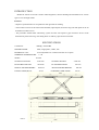
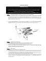
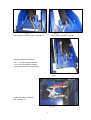
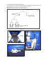
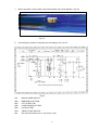
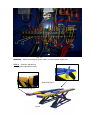
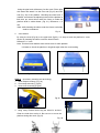
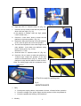
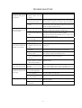
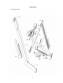
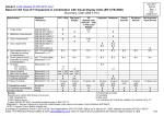
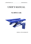
Model SL-12K-A
SCISSOR LIFT
wheel alignment model
(11000 LBS / 5000Kg Capacity)
INSTALLATION & OPERATION
INSTRUCTION
(SECOND EDITION)
2007. 6.
CONTENTS
Chapter 1 Introduction & Specifications --------------------------------------- page 3
Chapter 2 Packing list ------------------------------------------------------------- page 4
Chapter 3 Installation -------------------------------------------------------------- page 5
Chapter 4 Maintenance ------------------------------------------------------------ page 15
Chapter 5 Trouble shooting ------------------------------------------------------- page 16
Chapter 6 Appendix ---------------------------------------------------------------- page 17
2
INTRODUCTION
Model SL-12K-A scissor lift is used in wheel alignment, vehicle checking and maintenance for various
types of cars and light trucks.
Features:
- Superior synchronization in two platforms with graceful out looking.
- The movable recesses of the front wheel turntable (optional part) and extra long rear slide plate can be fit
for different models of cars.
- The pneumatic double-teeth self-locking system and the anti-explosive pipe insurance device works
automatically while lowering. The sliding block is made by super-friction materials.
SPECIFICATIONS
CAPACITY:
5000Kg / 11000 LBS
MOTOR POWER:
220V, single phase, 2.2Kw, 10A
HYDRAULIC OIL:
10-WT hydraulic oil or Dexron III ATF oil or equals
WORKING TEMPERATURE:
5 –40
≤76 db
NOISY:
OVERALL LENGTH:
6320 mm
OVERALL WIDTH:
PLATFORM LENGTH:
5030 mm
PLATFORM WIDTH:
MAX PLATFORM HEIGHT:
1870 mm
MIN PLATFORM HEIGHT:
LIFTING TIME (MAX):
50 sec
LOWERING TIME (MAX):
FIG. 1.
3
2120 mm
635 mm
180 mm
60 sec
PACKING LIST
Packing
Description
number
Standard parts
1
Oil hose and
accessory
2
3
Control cabinet
Main platform
4
5
6
Sub platform
Ramp
Hose cover
Detail information and quantity
1. M16 anchor bolts * 16 sets;
M18 anchor bolts * 4 sets;
2. Dia. 6*4 mm air hose * 1 set;
Dia. 8*5 mm air hose * 3 meter;
3. 1.5mm wire * 5 meter.
4. Flexible steel hose * 6 meter
5. Limit switch and wire * 1 set
6. High pressure oil hose * 8 pieces.
7. User’s manual
8. Dia 14mm combined seal washer * 2 pieces
9. Plastic strip * 10 pcs
10. Air hose connector dia 6, T shape, * 1 pc,
11. Air hose connector dia 6, elbow shape, * 1 pc,
12. Front stop board * 2 pcs, stop board support * 2 pcs
13. Hose cover ( elbow shape) * 1 pair
1. M16 height adjust bolts * 16 sets;
2. Height shim: 800mm * 2pcs, 150mm*2pcs.
Same as main platform above
Ramp with exile * 2 pcs,
1000mm*3 pcs, 950mm*2 pcs, 750mm*2 pcs
TOOLS REQUIRED IN INSTALLATION
Rotary hammer drill or similar
3/4” Masonry bit
Hammer
4 foot level
Open-end wrench set: 7/16” – 1-1/8”
Socket and ratchet set: 7/16” – 1-1/8”
Hex-key / Allen wrench set
Medium crescent wrench
Medium pipe wrench
Crow bar
Chalk line
Medium flat screwdriver
Tape measure: 25 foot minimum
Needle nose pliers
4
INSTALLATION
IMPORTANT NOTICE
These instructions must be followed to insure proper installation and operation of your lift. Failure
to comply with these instructions can result in serious bodily harm and void product warranty.
Manufacturer will assume no liability for loss or damage of any kind, expressed or implied
resulting from improper installation or use of this product.
PLEASE READ ENTIRE INSTRUCTION BEFORE STARTING TO ASSEMBLE THE LIFT
STEP 1: (Selecting Site) Before installing your new lift, check the following:
1. LIFT LOCATION: Always use architects plans when available. Check layout dimension
against floor plan requirements making sure that adequate space is available(See Fig.2). The
specified safety distances from walls must be 1000 mm at least. The room ceiling height
must be 4000 mm at least also.
2.
FLOOR REQUIREMNETS: The lift should be installed on a 3000 PSI concrete with little
gradients. Thickness of concrete≥150 mm. The leveling of whole area ≤ 10 mm.
FIG. 2.
STEP 2: (Unloading and Unpacking)
1. After unloading the lift, place it near the intended installation location.
2. Remove the shipping bands and packing materials from the unit.
3.
Remove the packing brackets and bolts holding the power unit. (Do not discard bolts, they
may be used in the assembly of the lift )
STEP 3: (Site Layout)
1. Determine which side will be the approach side.
2. Now determine which side you prefer the power unit to be located on. Note that the power unit
can be located on either side. It is helpful to try and locate the power unit with the driver side of
the vehicle when it is loaded on the lift to save steps during operation.
3. Once a location is determined, use a carpenter’s chalk line to layout a grid for the platform
locations. (See Fig.1). Keep all dimensions and square within 1/8 “, otherwise malfunction of
the lift will occur.
5
4.
Before continuing with the installation it is helpful to get a visual look of the shop and other
clearances. Also, this is a good time to drive a vehicle into the position and check for
adequate clearance.
NOTE
All models MUST be installed on 3000PSI concrete only confirming to the minimum
requirements. New concrete must be adequately cured by at least 28 days minimum.
STEP 4: (Platform installation)
1. Using forklift or crane to move the platforms to the desired location. Note: the turntable recess
shall be in the front and the rolling jack wheel notch shall be inside.
Note: Put the bottom steel sheet under the frame, holes to holes.
2.
Check the distance between the two platforms. The platforms shall be in parallel and the
diagonal of the two platforms shall be equal. (Difference less than 5 mm).
3.
Using forklift or crane to lift up the platform about
1000 mm as shown in Fig 3.
(Hint: Using two floor jacks to lift up the platform in two
ends a little then lift the whole platform in the middle. The
platform will be rested on the safety ladder)
FIG. 3
4.
Locate the power unit
position.( Fig 4 & Fig.5)
to
the desired
Main
platform
Sub
platform
Power unit
Fig. 4
Fig. 5
6
5.
Connecting the hydraulic hoses according to Fig. 6
Hose connection
Fig. 6
Note: Hose no. 7 and no. 8 has been connected in factory
Valve H (with handle) in this position shown is open.
7
Fig 7
Main cylinder connection (No. 4 and No.5 ).
Fig. 8
Sub cylinder connection ( No. 6).
Assistant cylinder connection
(No. 7 for main assistant cylinder
No. 8 for sub assistant cylinder)
(They are all fixed by manufacturer)
,
Fig 9
.
Power unit outlet connection
(No. 1 and No. 2)
Fig. 10
8
6. Connecting the air hose according to Fig.11
The air hose has been connected to the safety devices on the main and sub platform already. The
work in installation is to connect the hose to the power unit. ( Fig 4).
Warning: the air supply shall be cut off while connecting.
Fig. 11
Fig. 12
(L1/L2 or L3/L4 on platforms)
Fig. 13 (elec.-magnetic air valve K)
Fig. 14 (Air supply connector for rolling jack )
9
7.
Mount the switch on the inside of the bottom frame of the main platform ( Fig 15)
Fig. 15
8.
Connecting the cables to the power unit according to Fig. 16 &17
QS:
SB0:
SB1:
SB2:
SB3:
SQ1:
DQ:
Fig.16
MAIN POWER SWITCH
EMERGINCY BUTTON
LIFT UP BUTTON
LOWER DOWN BUTTON
LOCK BUTTON
HEIGHT LIMIT SWITCH
AIR VALVE (Position No.111 can be No. 109)
10
Fig. 17
WARNING: While connecting the power cable, cut off the power supply first.
STEP 5: (Platform adjustment)
1. platform longitudinal leveling
(Rear end) Fig.8
(Front end) Fig.19
Fig.20
11
Using the pipe level will be easy for this work. Fill the pipe
with water and attach it to the front end (Fig.19) and rear
end (Fig. 20) of the platform. Checking the water level, if
needed, screw down the adjusting bolts to lift the platform a
little then put some shims under the frame to make the
platform level in whole distant. (Fig. 21). Difference <= 5
mm.
Note: while inserting the shims under the frame, both sides
shall be considered.
Fig. 21
2. cross section
By using the level (Fig 22) or the pipe level (fig.23), it is easy to level the platform in cross
section by inserting the shims under the bottom frame.
Difference <= 3 mm.
Note: This level work shall be done at both ends for each platform.
It is better to check the platform in longitude again after the cross leveling.
Fig. 22
Fig.23
STEP 6: (accessory mounting and anchoring)
1. Rear ramps mounting.( Fig. 24)
2. Front stops mounting. (Fg.25)
3. Hose cover mounting (Fig.26)
Fig.25
Fig.24
4. Using rotary hammer drill to dig the holes for anchors.
Clean the hole then anchor it. Be sure not to move the
platform during this work. (Fig.27)
Fig. 26
12
Fig.27
WARNING: Before carrying out the following steps, please check again all hoses and cables.
Carefully check the power supply ( 220V, 1ph, 20A ) and compressed air supply (6-8
bars).
STEP 7: (Platform initializing and leveling)
1. Turn on the main power switch (Fig.28) and
compressed air supply valve. Open the cabinet door
of the power unit on the back to find the valve “H”
and “ G”.
2. Close the valve “H” by turn the handle 90 degree to be
parallel to the pipe. Open the valve “G” by counter
clockwise turning. (Fig. 29)
3. Press the “Lift up” button on the power unit to raise
the main platform to about 1000 mm high.( Fig. 30)
(f the platform is already 1000 mm high, please raise
it a little more.)
4. Press the “Lower down“ button to lower the main
platform to lowest position. (Fig. 31)
5. Press the “Lift up” button again to raise the main
platform to 1400 mm. (Fig.32)
Fig. 29
Fig. 30
Fig.28
Fig.31
13
Fig. 32
6. Open the valve “H”. Close the valve “G” .(Fig. 33)
7. Press the “lift up” button to raise the sub platform to
about 1000 mm high.( Fig. 32)
(If the platform is already 1000 mm high, please
raise it a little more.)
8. Press the “ lower down” button to lower the sub
platform to the lowest position ( Fig. 34)
9. Repeat the lifting and lowering of the sub platform
for 6-7 times to get the air out of the cylinders.
10. Then lift the sub platform to the same height of the
main platform. Level these two platforms using
level or water pipes.( Fig. 35-36)
Difference <= 3 mm.
11. Close the valve “H”. Open the valve “G”. (Fig. 29)
12. Press the “lift up“ button to raise both platform to
1700mm high. Adjust the position of the limit
switch on the bottom frame. (Fig.37) Raise up the
platform to tough the limit switch to check it works.
Note: The ceiling height shall be considered in this
adjustment.
Fig. 33
Fig. 34
Fig. 35
Fig. 36
Height limit switch The lift is ready for working now.
Fig.37
MAINTENANCE
1. Daily
a. Check power supply cables, compressed air hoses, oil hoses before operation.
b. Check the voltage of the power supply and the pressure of the compressed air.
c. Check the parallel and leveling of the platforms.
2. Monthly
14
a. Check the leveling between the platforms. If necessary, do as following steps.
z
First lift up the platforms to about 1400 mm high without loading.(Fig. 30)
z
Close the valve “G”, open the valve “ H”. (Fig.33)
z
Press the “lift up” or “lower down” button to make the sub platform same height as
the main platform using level or water pipe level.(Fig 35-36)
z
Close the valve “H”, open the valve “ G”. (Fig. 29) Now the lift is ready for working.
b. Grease the necessary part of the lift such as sliding plate on the bottom frame, upper
rolling dolly, shafts and the safety locking bars.
c. Check all anchor bolts on the bottom frame and tighten them up in necessary.
d. Chang the oil in tank after first three months or 10 hours accumulated working hours.
3. Yearly
a. Clean the filter of the oil tank and change the oil totally with new one.
b. Check all parts of the lift for any possible problem.
15
TROUBLE SHOOTING
Fault
The motor does not start
although the lifting-up has
been pressed.
In lifting operation, the
motor runs, but there is no
lifting movement.
When press
“Lower down” button, the
platform is not lowered.
The lift lowers extremely
slowly under normal loads.
The platforms are not
synchronous and not in the
same height.
Noisy lifting and lowering.
Possible cause
Connection of power
supply cables are not
correct.
The contactor (KM in
Fig.16) in the circuit of the
motor does not work.
The limit switch is not
work.
The motor turns inverse.
Lifting with light load is
normal but not with heavy
load.
The hydraulic oil in tank
is not enough.
The valve “G” is not
open.( Fig. 16)
The safety locks are not
released form the safety
teeth.
The safety locking pawl is
not lifted.
The solenoid air valve
does not work.
The lowering solenoid
valve is energized but does
not work.
The hydraulic oil has too
high viscosity or frozen,
deteriorated (in Winter).
The “antiknock valve” for
preventing oil pipe burst is
blocked.
The air in the oil cylinder
is not vent completely.
Oil leakage on oil pipe or
at its connections.
The valve “H” can not
be closed totally.
Lubrication is not enough.
The base or the lift frame
is twisted.
Solutions
Check and re-connect the cables.
If the motor starts when forcing the contactor closed down
with an isolated rod, check the control circuit. If the voltage at
two ends of the contactor coil is normal, replace the contactor.
Short-circuit terminal 10# and 0#, which are connected with
the limit switch, and if the trouble disappears, check the limit
switch, or replace it with a new one.
Change the phases of the power supply cables. Or call
engineer to change the connection inside the motor.
The safe pressure of the over-flow valve (E in Fig 16) shall be
increased by turning the knob clockwise slightly.
The spool of the lowering solenoid valve (C in Fig .16) is
stuck by dirt. Clean the spool.
Add some hydraulic oil to the tank.
Turn counter clockwise and open the valve “G”.
First lift up the platform a little to open the safety lock then
lowering it.
The air pressure is not high enough to lift up the safety
locking pawl. Please increase the pressure be 6-8 bar.
If the solenoid air valve is energized, but does not open the air
loop, check or replace the solenoid air valve.
Check the plug and coil of the lowering solenoid valve. Check
the tightness of its lock nut on the coil.
Replace with new hydraulic oil in accordance with the
instruction book.
Shut off air supply and thus lock the safety pawl of the lift
Remove the “antiknock valve” from the oil supply hole at the
bottom of the cylinder, then clean the “antiknock valve”.
Refer to STEP 7 in INSTALLATION.
Tighten oil pipe connectors or replace oil seals then initialize
the system and do leveling again.
Replace valve “H”, and then level the platforms.
Lubricate all hinges and motion parts (including piston rod)
with oil or grease.
Again level the platforms and make the bottom frames stable.
16
APPENDIX
1. PARTS DRAWING
17