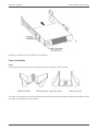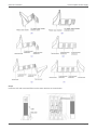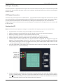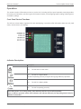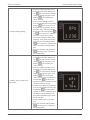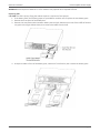
1
G90 Online UPS 1000VA, 2000VA, 3000VA Models User & Installation Manual www.xpcc.com | © 2015 Xtreme Power Conversion Corporation. All rights reserved. (Rev 2/5/15) G90 User’s Manual Uninterruptible Power Supply Table of Contents Introduction.................................................................................................7 Product Description......................................................................................7 Double Conversion Online Technology............................................................................................7 Diagnostic Tests...............................................................................................................................8 System Configuration...................................................................................8 Communication Connections.........................................................................................................10 Emergency Power Off (EPO) Port...................................................................................................11 Hardware Installation Guide.......................................................................12 Safety Information.........................................................................................................................12 Storage and Transportation...........................................................................................................12 Environment...............................................................................................13 UPS Installation..........................................................................................13 Connecting the UPS Internal Batteries...........................................................................................13 Connecting Extended Battery Packs (EBPs)...................................................................................15 Rack-mount Installation.................................................................................................................17 Tower Installation..........................................................................................................................19 UPS Input Connection....................................................................................................................21 UPS Output Connection.................................................................................................................21 Starting the UPS............................................................................................................................ 21 Operations.................................................................................................23 Front Panel Control Functions.......................................................................................................23 Indicator Descriptions....................................................................................................................23 Button Descriptions.......................................................................................................................24 Working Status of Indicators..........................................................................................................24 Display Functions...........................................................................................................................25 Parameters Inquiring.....................................................................................................................27 User Settings..................................................................................................................................29 Operating Mode Description.......................................................................33 Xtreme Power Conversion Corporation Page 2 G90 User’s Manual Uninterruptible Power Supply Startup Operation..........................................................................................................................34 Shutdown Operation......................................................................................................................34 UPS Self-Test/Mute Test Operation................................................................................................35 Configuring Battery Settings..........................................................................................................35 Using UPS with Generator...........................................................................35 Communication..........................................................................................36 Installing Communication Options and Control Terminals............................................................36 Troubleshooting.........................................................................................39 Fault Codes....................................................................................................................................40 UPS Maintenance..........................................................................................................................40 UPS and Battery Care.................................................................................................................... 40 Storing the UPS and Batteries........................................................................................................41 Maintenance..................................................................................................................................41 Replacing Batteries (QUALIFIED SERVICE PERSONNEL ONLY)........................................................41 Replacing Battery Trays in UPS and EBPs.......................................................................................42 Specifications.............................................................................................45 Shipping List.............................................................................................. 46 Obtaining Service.......................................................................................47 Xtreme Power Conversion Limited Warranty...............................................48 Appendix A: G90-EBP1, G90-EBP2 User Guide.............................................49 Introduction...................................................................................................................................49 Installation.....................................................................................................................................49 Operation.......................................................................................................................................51 Maintenance..................................................................................................................................51 Testing New Batteries....................................................................................................................53 Recycling the Used Battery............................................................................................................53 Specifications.................................................................................................................................54 Xtreme Power Conversion Corporation Page 3 G90 User’s Manual Uninterruptible Power Supply Thank you for selecting this uninterruptible power supply (UPS). It provides you with protection for connected equipment. Please read this manual before installing the G90 Series UPS models G90-1000, G90-2000, or G903000 as it provides important information that should be followed during installation and maintenance of the UPS and batteries, allowing you to correctly set up your system for the maximum safety and performance. Included is information on customer support and service, if it is required. If you experience a problem with the UPS, please refer to the Troubleshooting section in this manual to correct the problem. If the problem is not corrected, please collect information so that the Technical Support personnel can more effectively assist you. Xtreme Power Conversion Corporation Page 4 G90 User’s Manual Uninterruptible Power Supply Important Safety Instructions: (Save These Instructions) CAUTION! (UPS having Internal Batteries): Risk of electrical shock – Hazardous live parts inside this unit are energized from the battery supply even when the input AC power is disconnected. CAUTION! (No User serviceable Parts): Risk of electrical shock, do not remove cover. No user serviceable parts inside. Refer servicing to qualified service personnel. CAUTION! (Non-isolated Battery supply): Risk of electric shock, battery circuit is not isolated from AC input, hazardous voltage may exist between battery terminals and ground. Test before touching. WARNING! (Fuses): To reduce the risk of fire, replace only with the same type and size of fuse. WARNING! Unit intended for installation in a controlled environment. CAUTION! Do not dispose of batteries in a fire, the battery may explode. CAUTION! Do not open or mutilate the battery, released electrolyte is harmful to the skin and eyes. CAUTION! A battery can present a risk of electric shock and high short circuit current. The following precaution should be observed when working on batteries: • Remove watches, rings or other metal objects. • Use tools with insulated handles. To reduce the risk of electric shock, disconnect the UPS from the main supply before installing a computer interface signal cable. Reconnect the power cord only after signaling interconnections have been made. Servicing of batteries should be performed or supervised by personnel with knowledge of batteries and the required precautions. Keep unauthorized personnel away from batteries. These UPS units are extremely heavy. Caution should be taken in moving and positioning equipment. The instructions contained within this safety manual are deemed important and should be closely followed at all times during installation and follow-up maintenance of the UPS and batteries. Xtreme Power Conversion Corporation Page 5 G90 User’s Manual Uninterruptible Power Supply CAUTION The unit has a dangerous amount of voltage. If the UPS indicator is on, the unit’s outlets may have a dangerous amount of voltage even when not plugged into the wall outlet because the battery may continue to supply power. Care should be taken to undertake installation indoors, free from electrically-conductive particles which are under temperature and humidity control, in order to reduce the risk of electric shock. It is best to disconnect the device using the power supply cord. Ensure that the equipment is placed in a position near the outlet where easily accessible. Except for replacing the batteries, all servicing on this equipment must be carried out by qualified service personnel. Before conducting any maintenance, repair, or shipment, first ensure that everything is turned off completely and disconnected. For additional safety instructions, please use the Safety Manual as a reference. Special Symbols The following symbols used on the UPS warn you of precautions: RISK OF ELECTRIC SHOCK - Please observe the warning that a risk of electric shock is present CAUTION: REFER TO OPERATOR’S MANUAL - Refer to the operator’s manual for additional information, such as important operating and maintenance instructions. SAFE GROUNDING TERMINAL - Indicates primary safe ground LOAD ON/OFF – Pressing the button turns on/off the output receptacles and the indicator light. RJ45 RECEPTACLE – The receptacle provides network interface connections and telephone or telecommunications equipment should not be plugged into it. Please do not discard of the UPS or the UPS batteries as the UPS may have valve-regulated lead-acid batteries. Please recycle batteries appropriately. Xtreme Power Conversion Corporation Page 6 G90 User’s Manual Uninterruptible Power Supply Introduction The information provided in this manual covers single phase 1000 – 3000 VA uninterruptible power system, their basic functions, operating procedures, options available and emergency situations. It also includes information on how to ship, store, handle, and install the equipment. Only detailed requirements of the UPS units are described herein, and installation must be carried out in accordance with this manual. Electrical installation must also carefully follow local legislation and regulations. Only qualified personnel should conduct these installations as failure to acknowledge electrical hazards could prove to be fatal. Product Description Many different kinds of sensitive electrical equipment can be protected by an Uninterruptible Power Supply (UPS) including computers, workstations, process control systems, telecommunications systems, sales terminals, other critical instrumentation, etc. The purpose of the UPS is to protect these systems from poor quality utility power, complete loss of power, or other associated problems. Electrical interference exists in many forms, causing problems in AC power, from lightning, power company accidents and radio transmission motors, air conditioners, and vending machines. Protection of sensitive electrical equipment is vital to protect against power outages, low or high voltage conditions, slow voltage fluctuations, frequency variations, differential and common-mode noise, transients, etc. To prevent power line problems from reaching critical systems causing damage to software, hardware, and equipment malfunctions, the UPS maintains constant voltage, isolating critical load output and cleaning the utility AC power. Double Conversion Online Technology A double conversion on-line technology UPS provides completely isolated, clean, uninterrupted single-phase power to your critical systems, while maintaining the batteries for their maximum potential. In the event that the power failure lasts longer than the UPS backup time, the UPS will shut down avoiding battery damage. When the input AC voltage returns, the UPS will automatically return online to recharge the batteries. As shown in block diagram: • An input filter reduces transients on the incoming utility. • To maintain full battery charge, the AC input power is rectified and regulated in the rectifier feeding power to the battery converter and inverter. • DC power is converted to AC in the inverter, passing it on to the load. • Power is maintained from the battery during a power failure. • The converter increases voltage appropriately for the inverter. Xtreme Power Conversion Corporation Page 7 G90 User’s Manual Uninterruptible Power Supply Block Diagram Diagnostic Tests When the UPS is started, a diagnostic test is automatically executed, checking the electronics and batteries, reporting any problems on the LCD display. System Configuration The UPS device and the internal batteries make up the system. Depending on the site and load requirements of the installation, certain additional options are available for the solution. Planning a UPS system, the following should be taken into consideration: • The total demand of the protected system shall dictate the output power rating (VA). Allow a margin for future expansion or calculation inaccuracies from measured power requirements. • Backup time required will indicate the battery size needed. If the load is less than the UPS nominal power rating, then actual backup time is longer. • The following options are available: o Connectivity Options SNMP/WEB card Dry contact card o Extended Battery Packs G90-EBP1 for use with the G90-1000 G90-EBP2 for use with the G90-2000 and G90-3000 See the Specification section of this manual for additional model information. Xtreme Power Conversion Corporation Page 8 G90 User’s Manual Uninterruptible Power Supply UPS FRONT VIEW EBP FRONT VIEW G90-1000 REAR VIEW DIAGRAM G90-2000 REAR VIEW DIAGRAM G90-3000 REAR VIEW DIAGRAM Xtreme Power Conversion Corporation Page 9 G90 User’s Manual Uninterruptible Power Supply G90-EBP1 BATTERY PACK REAR VIEW DIAGRAM G90-EBP2 BATTERY PACK REAR VIEW DIAGRAM FRONT PANEL Communication Connections To allow for unattended UPS shutdown/start-up and status monitoring, connect one end of the communication cable to the USB/RS232 port and the other to the communications port on your PC or server. With the monitoring software installed, the UPS can be scheduled for shutdown/start-up and monitoring of the UPS status through the PC or server. Xtreme Power Conversion Corporation Page 10 G90 User’s Manual Uninterruptible Power Supply RS232 Communications The RS-232 interface uses a 9-pin female D-sub connector. Information provided includes data about utility, load and the UPS. The interface port pins and their functions are identified in the following table: PIN # 1,4,6,7,8,9 2 3 5 FUNCTIONS Reserved UPS transmit UPS receive Ground SNMP Communications Option The UPS provides an intelligent slot for internal or external network card. This special intelligent network card can be compatible with popular software and hardware found on the web and in operating systems. It can support operating systems such as HP Open View, IBM Netview, SUN Netmanager, etc. This enables the UPS to provide instant UPS and power information over the network. Please contact your reseller for additional details. Emergency Power Off (EPO) Port A customer supplied switch located remotely can be used to close the EPO connection and allows the UPS output receptacles to be switched off. Since the EPO shuts down the equipment immediately, orderly shutdown procedures are not followed by any power management software. The UPS will have to be manually restarted in order to regain power to the outlets on the UPS. Keep Pin 1 and Pin 2 closed for UPS normal operation. To activate EPO function, cut the wire between Pin 1 and Pin 2. Warning: The EPO circuit is an IEC 60950 safety extra low voltage (SELV) circuit. This circuit must be separated from any hazardous voltage circuits by reinforced insulation. Caution: The EPO must not be connected to any utility connected circuits. Reinforced insulation to the utility is required. The EPO switch must have a minimum rating of 24VDC and 20mA, and be a dedicated latchingtype switch, not tied to another circuit. The EPO signal must remain active for at least 250ms for proper operation. To ensure the UPS stops supplying power to the load during any mode of operation, the input power must be disconnected from the UPS when the emergency power off function is activated. Note: For Europe, the emergency switch requirements are detailed in Harmonized document HD-384-48 S1, “Electrical Installation of the Buildings, Part 4: Protection for Safety Chapter 46: Isolation and Switching”. Xtreme Power Conversion Corporation Page 11 G90 User’s Manual Uninterruptible Power Supply Hardware Installation Guide Inspect the UPS upon receipt. The packaging is recyclable; keep it for reuse or dispose of properly. Safety Information Information presented here is vital to all personnel. Please read all Safety information. Storage and Transportation Please handle the UPS and associated equipment with extreme caution since a high amount of energy is contained in the batteries. Always keep the unit in an upright position as marked on the packaging, and never drop the unit. Please adhere to the following instructions if the UPS is not installed immediately: • Store the equipment as is in its original packing and shipping carton. • Do not store in temperatures outside the range of -15°C to +25°C • Ensure that the equipment is fully protected from wet or damp areas and from moist air. In order to maintain the batteries, the UPS should be recharged every 6 months for at least 8 hours. If flammable substances such as gases or fumes are present, or if the room is airtight, a hazardous situation may exist in which no electrical equipment should be operated. The instructions in this manual explain how to install the UPS safely. Not acknowledging such electrical hazards may be fatal – keep this manual for future reference. WARNING! It is strongly recommended that the UPS cabinet not be opened as components have very high voltage and touching those components may be fatal. Only a qualified technician or authorized agent may service the unit. The UPS unit’s output receptacles carry live voltage even when not connected to an input voltage source. The UPS has its own internal energy source. Xtreme Power Conversion Corporation Page 12 G90 User’s Manual Uninterruptible Power Supply Environment Ensure that all environmental concerns and requirements are met according to specifications listed in this document, otherwise the safety of installation personnel cannot be guaranteed, and the unit may malfunction. Ensure that you remember the following when locating the UPS system and battery options: • Avoid extremes of temperature and humidity. Maximum battery life can be attained with a recommended temperature range of +15°C to +25°C. • Provide protection for the equipment from moisture. • Space and ventilation requirements must be met. Ensure there is 100mm behind and 50mm on the sides of the UPS for proper ventilation. • Ensure that the front of the UPS remains clear for user operation. UPS Installation Installation and wiring must be performed in accordance with the local electrical laws and regulations, and performed by appropriate personnel. For safety considerations, the UPS is shipped from the factory without connecting the battery wires. Before installing the UPS, please follow these steps for connection of the battery wires. Connecting the UPS Internal Batteries Step 1 Remove the front cover of the UPS by holding in the cover side with the LCD display, then un-snap the other side of the front panel from the UPS. The front panel should now easily be removed from the LCD side. Note: A ribbon cable connects the LCD to the cover of the UPS. Do not pull on the cable or disconnect it. Xtreme Power Conversion Corporation Page 13 G90 User’s Manual Uninterruptible Power Supply Step 2 Caution: A small amount of arcing may occur when connecting the internal batteries. This is normal and will not harm personnel. Connect the cables quickly and firmly. Connect the internal battery connector - connect red to red, pressing the connector tightly together to ensure proper connectivity. If installing an Extended Battery Pack (EBP) see the section titled Connecting EPBs before continuing with the UPS installation Step 3 Replace the UPS front cover, verifying that the ribbon cable is protected, and if EBPs are installed, that the EBP cable is routed through the knockout on the bottom of the cover. Xtreme Power Conversion Corporation Page 14 G90 User’s Manual Uninterruptible Power Supply Attach the UPS front cover by reversing the process in Step 1 – installing the LCD side first and then gently snapping the other side into the ports on the UPS. Step 4 If you are installing power management software, connect your computer to one of the communication ports or optional connectivity card, using appropriate cable. Step 5 If your rack has conductors for grounding or bonding of ungrounded metal parts, connect the ground cable (not supplied) to the ground bonding screw on the rear of the UPS as shown in the example below. Step 6 If an emergency power off (disconnect) switch is required by local codes, see “Remote Emergency Power off (REPO)” section to install the REPO switch before powering on the UPS. Continue to “UPS Internal Startup”. Connecting Extended Battery Packs (EBPs) Step 1 Remove the front cover of the UPS and each EBP by holding in the cover side with the LCD display, then un-snap the other side of the front panel from the UPS. The front panel should now easily be removed from the LCD side. Note: a ribbon cable connects the LCD to the cover of the UPS. Do not pull on the cable or disconnect it. Xtreme Power Conversion Corporation Page 15 G90 User’s Manual Uninterruptible Power Supply Step 2 On the bottom of the UPS front cover, remove the EBP Cable Knockout as shown in the diagram below. For the bottom EBP, remove the EBP Cable Knockout on the top of the EBP front cover. If you are installing more than one EBP, for each additional EBP, remove the EBP Cable Knockout on the top and bottom of the EBP front cover. Step 3 Caution: A small amount of arcing may occur when connecting the internal batteries. This is normal and will not harm personnel. Connect the cables quickly and firmly. Connect the EBP cables into the battery connector(s) - connecting black to black – press the connectors tightly together to ensure proper connection. To connect the second EBP, unclip the EBP connector on the first EBP and pull gently to extend the wiring to the EBP connector on the second EBP. Repeat for any additional EBPs. Xtreme Power Conversion Corporation Page 16 G90 User’s Manual Uninterruptible Power Supply Verify that the EBP connections are tight and there are adequate bend radiuses and strain relief exists for each cable. Step 4 Replace the front covers on the UPS and EBPs, verifying the EBP cables are routed through the EBP cover knockouts. Clip the left side of each EBP in place first before connecting the right side. Repeat for each EBP. This is the same installation procedure as used for the UPS earlier. Assure that the wires connected between the UPS and EBP are installed behind the front covers and not accessible to the user. Rack-mount Installation Caution: The UPS and EBPs are heavy. Removing the units from its carton requires a minimum of two people. If installing optional EBPs, make sure to install the EBPs directly below the UPS so that all wiring between the cabinets is installed behind the front covers and inaccessible to users. Note: Rail Kits are required for each individual UPS and EBP to be installed. Step 1 Assemble the left and right rails to the rear rails as sown in the diagram below. Do not tighten the screws yet. Adjust each rail size for the depth of the rack. Step 2 Select the proper size in the rack for positioning the UPS. The rail occupies four positions on the front and rear of the rack. Xtreme Power Conversion Corporation Page 17 G90 User’s Manual Uninterruptible Power Supply Tighten four M5 Umbrella Nuts in the side of rail assembly Fix one rail assembly to the front of the rack with one M5 x 12 pan-head screw and one M5 cage nut. Use two M5 cage nuts and two M5 x 12 pan-head screws to fix the rail assembly to the rear of the rack. Tighten all screws and nuts. Repeat steps for the other rail assemblies. Step 3 Place the UPS or EBP on a flat, stable surface with the front of the UPS or EBP facing you. Align the mounting brackets with the screw holes on each side of the UPS or EBP and fix with supplied M4 x 8 flathead screws. Slide the UPS or EBP into the rack. Secure the front of the UPS to the rack using one M5 x 12 pan-head screw and one M5 cage nut on each side. Install the bottom screw on each side through the bottom hoes of the mounting bracket and the bottom hole of the rail. Xtreme Power Conversion Corporation Page 18 G90 User’s Manual Uninterruptible Power Supply Repeat for all additional UPS or EBP for the installation. Tower Installation Step 1 Two plastic base brackets intercross and flatten to make a single unit tower bracket. If an EBP is to be placed in the tower configuration with the UPS, extension boards are added in the middle to make the tower bracket larger as shown below. Xtreme Power Conversion Corporation Page 19 G90 User’s Manual Uninterruptible Power Supply Step 2 Install the UPS and associated EBPs into the tower brackets as shown below. Xtreme Power Conversion Corporation Page 20 G90 User’s Manual Uninterruptible Power Supply UPS Input Connection Connect the UPS to an approved electrical input source consistent with the input power cord connection provided with the UPS. Do not replace the power cord or use a substitute. Avoid using extension cords when connecting AC input to any UPS. UPS Output Connection There are two types of output on the G90 models - programmable outlets and general outlets. Please connect non-critical devices to the programmable outlets and critical devices to the general outlets. During power failure, you may extend the backup time to critical devices by setting shorter backup time for non-critical devices. Programmable outlets can also be used to re-cycle the power to remote devices if required to re-start a server due to lock-up issues. Starting the UPS Note: Verify that the total equipment ratings do not exceed the UPS capacity to prevent an overload alarm. 1. 2. 3. 4. 5. 6. If optional EBPs are installed, verify that the EBPs are connected to the UPS. Plug the equipment to be protected into the UPS, but do not turn on the protected equipment. Make any necessary provisions for cord retention and strain relief. Plug the detachable UPS power cord into the input connector on the UPS rear cover. Plug the UPS power cord into a power outlet. The UPS front cover display illuminates. The UPS will do a self-test when power on. After the self-test is completed, the charger will charge the batteries. If the output display on the LCD is “0” there is no output. If you need the UPS output from the utility without starting the UPS when plugged into the utility, then the bPS option needs to be set to “ON” - see instructions for the bPS in this manual. 7. Press the combination of start buttons on the UPS front cover for at least ½ second. The UPS will start and the LEDs will turn on and off sequentially. 8. Check the UPS front panel display for active alarms or notices. Resolve any active alarms before continuing. See “Troubleshooting” section in this manual for additional information on resolving alarm conditions. LED is illuminated, do not proceed until all alarms are clear. Check the UPS status from the front If the panel to view active alarms. Correct the alarms and reset if necessary. Xtreme Power Conversion Corporation Page 21 G90 User’s Manual Uninterruptible Power Supply 9. Verify that the LED is illuminated solid, indicating that the UPS is operating normally and any loads are powered. 10. If optional EBPs are installed, see “Configuring Battery Settings” section in this manual to set the number of installed EBPs. 11. To change any other factory-set defaults, see “User Settings” section in this manual. Note: At initial startup, the UPS sets system frequency according to the input line frequency (input frequency autosensing is enabled by default). Note: At initial startup, please set the output voltage needed before startup of the UPS. After the subsequent startup, the UPS will output the setting voltage. 12. If you installed an optional EPO, test the EPO function: Activate the external EPO switch. Verify the status change on the UPS front panel display. Deactivate the external EPO switch and restart the UPS. Note: The internal batteries charge to 80% capacity in less than 5 hours. However, it is recommended that the batteries should be charged for 48 hours after installation or long-term storage. If optional EBPs are installed, see the recharge times listed in this manual. Xtreme Power Conversion Corporation Page 22 G90 User’s Manual Uninterruptible Power Supply Operations This section contains information on how to use the UPS, including the front panel operation, operating modes, UPS startup and shutdown, transferring the UPS between modes, and configuring bypass settings, load segments, and battery settings. Front Panel Control Functions The UPS has a three-button segmental LCD with backlighting. It provides useful information about the UPS, load status, measurements, and settings. Indicator Descriptions Indicator Description ON The UPS has an active alarm ON The UPS is in Bypass Mode The UPS is operating normally on bypass during High Efficiency operation ON The UPS is in Battery Mode ON The UPS is operating normally Note: When power on or during startup, these indicators will turn on and off sequentially. Note: In different operation modes these indicators will indicate differently. See Operating Modes Table for additional information. Xtreme Power Conversion Corporation Page 23 G90 User’s Manual Uninterruptible Power Supply Button Descriptions Button Startup combination + Rotating combination + Description Press and hold these buttons for more than ½ second to turn on the UPS or to turn off the UPS Press and hold these buttons for more than 2 seconds to rotate the LCD for rack or tower configuration Press and hold these buttons for more than 1 second in Line Mode or ECO Battery test/mute combination Mode: UPS runs self-test function Press and hold these buttons for more than 1 second in Battery Mode: UPS + runs mute function Non-function Setting Mode: Press and hold this button for more than ½ second (less than 2 seconds): indicates the items of the LCD item section in order Press and hold this button for more than 2 seconds: orderly displays a looping sequential view of the items every 2 seconds, when press and hold the button Scroll for some time again, display will turn to output status OR Function Setting Mode: Press and hold the button for more than 1 second (less than 2 seconds): affirm the Set Option, Press and hold the button for more than 2 seconds to exit from this function setting interface Non-function Setting Mode: Press and hold the key for more than 2 seconds: Function setting interface Function Setting Mode: Setting entry Press and hold this button for more than ½ second (less than 2 seconds): Affirms the set option, Press and hold the button for more than 2 seconds, exit from the function setting interface Working Status of Indicators No. 1 2 Working Status Line Mode Normal voltage High/low voltage protection, turn to battery mode Battery Mode Normal voltage 3 Battery voltage abnormal warning Bypass Mode Main AC normal voltage in Bypass Mode Xtreme Power Conversion Corporation Nor Indication Bat Bps Warning Fau ● ● ● � ● ● � ● � � ● Remarks � None Once every 4 seconds Once every 4 seconds Once per second Once every 2 minutes Eliminate after start the UPS Page 24 G90 User’s Manual 4 Uninterruptible Power Supply Main AC high voltage warning in Bypass Mode Main AC low voltage warning in Bypass Mode Battery disconnect warning � � Bypass Mode Inverting Mode ● ● � Once every 4 seconds � Once every 4 seconds Power up or start 5 Output overload protection Overload warning in Line Mode Overload in Line Mode protection Overload warning in Battery Mode Overload in Battery Mode protection Overload warning in Bypass Mode Once every 4 seconds Once every 4 seconds 6 times Check to determine if the battery switch is closed Check to determine if the battery switch is closed Check to determine if battery is connected properly Remove uncritical loads Remove uncritical ● ● Long beeps loads Remove uncritical ● ● 2 per second � loads Remove uncritical ● ● ● Long beeps loads Once every 2 Remove uncritical ● 6 � seconds loads Once every 2 Check if the fan is 7 Fan fault (fan icon flashing) � � � � seconds blocked by an object If display fault code and icon lights, contract dealer, dis8 Fault Mode ● Long beeps tributor or manufacturer for additional support ● = indicator lights for a long time; � = indicator flashes; � = status of indicator depends on other conditions ● � 2 per second Display Functions As the default or after 5 minutes of inactivity, the LCD displays the output parameters. The backlit LCD automatically dims after 5 minutes of inactivity. Press any button to restore the screen. LCD display comprises numerical value section, capacity graphics section, fan-status graphics section, and charger-status graphics section. See the table below for details. Xtreme Power Conversion Corporation Page 25 G90 User’s Manual Uninterruptible Power Supply Section Description Numerical value section Display the corresponding numerical value of inquiring items (output, load, temperature, input, battery), for example, the graphic shows the output voltage is 230V, the output frequency is 50Hz Capacity graphics section Display the capacity of the battery and load. Every pane represents 20% capacity. As the graphic shows, the capacity of the battery is 80100% (5 panes), the load reaches 40-60% (3 panes). When the UPS is overloaded, the icon will flash, when the battery is weak or disconnected, the icon will also flash. Fan-status graphics section Display if the fan works normally. When the fan works normally, it will show the dynamic fan blades rotating; when the fan works abnormally, the icon will keep flashing with the warning. Charger-status graphics section Displays the status of the charger. When charger works normally, the corresponding icon will vary dynamically and orderly, when the charger works abnormally, the icon will keep flashing. When the UPS is in Battery Mode, the number of icons of the charger-state section will vary according to the chargeable capacity of the battery. Xtreme Power Conversion Corporation Graphic Page 26 G90 User’s Manual Uninterruptible Power Supply Parameters Inquiring Press and hold the scroll button or for more than ½ second (less than 2 seconds) to inquire about items. The inquired items include input, battery, output, load, temperature. Press and hold the scroll button for more than 2 seconds, LCD begins to display the items circularly and orderly which transfer to another every 2 seconds. Press and hold the button for some time again to return to output status. Item Description Output Display the output voltage and output frequency of the UPS. As shown in the graphic, the output voltage is 230V and the output frequency is 50Hz Load Display the numerical value of the active power (WATT) and apparent power (VA) of the load. As shown in the graphic, the WATT of the load is 100W, the VA is 100VA (when the load is disconnected it is normal for a small numerical value to show). Temperature Display the temperature of the inverter in the UPS. As shown in the graphic, the temperature of the inverter is 37°C. Input Display the voltage and frequency of the input. As shown in the graphic, the input voltage is 210V, the input frequency is 49.8Hz. Xtreme Power Conversion Corporation Graphic Page 27 G90 User’s Manual Uninterruptible Power Supply Battery Display the voltage and capacity of the battery. As shown in the graphic, the battery voltage is 38V, the capacity of the battery is 100% (the capacity of the battery is an estimate based upon the battery voltage). Battery remaining time Display the battery remaining time when under battery mode. The number is from 0 to 999 minutes. As shown in the graphic, there are 686 minutes of battery time remaining. Xtreme Power Conversion Corporation Page 28 G90 User’s Manual Uninterruptible Power Supply User Settings The UPS has setting functions. The user settings can be done under any of the UPS working modes. The setting will take effect under certain conditions. The table below describes the User Settings. Setting Function (serial number) 1 - ECO function setting Setting Procedure 1. Enter the setting interface. Press and hold the Function Setting button for more than 2 seconds, the letters “ECO” flash. 2. Enter the ECO setting interface. Press and hold the Function Setting button for more than ½ second (less than 2 seconds), the letters “ECO” will stop flashing. The “ON” (or OFF) below the ECO will flash. Press and hold the scroll button for more than ½ second (less than 2 seconds) to determine whether the ECO function is enabled or disabled. 3. Confirm the ECO selecting interface. After selecting ON or OFF, press and hold the function setting button for more than ½ second (less than 2 seconds). Now the ECO setting function is completed and the “ON” or “OFF” below the “ECO” will light without flashing. 4. If “OFF” is chosen go to step 7, otherwise go to step 5. 5. Set the ECO tolerance range. Briefly press the scroll button or for more than ½ second (less than 2 seconds) to select the voltage range in percentage +5%,+10%,+15%,+25%(default), then briefly press the function setting button for more than ½ second (less than 2 seconds) to confirm selection. 6. Then set the minus range in a similar manner. 7. After the minus range is confirmed, press the function setting button for more than 2 seconds to exit setting menu. Xtreme Power Conversion Corporation Graphic Page 29 G90 User’s Manual 2 - Bypass function setting Uninterruptible Power Supply 1. Enter the setting interface. Press and hold the function setting butfor more than 2 seconds ton stepping through using the scroll until reaching the button “bPS” flashing. 2. Enter the BPS setting interface. Press and hold the function setting for more than ½ secbutton ond (less than 2 seconds). At this time the “bPS” will stop flashing. The “ON” (or OFF) below the bPS will flash. Press and hold the scroll for more than ½ second key (less than 2 seconds) to determine whether the BPS function is enabled or disabled. 3. Confirm the BPS selecting interface. After selecting ON or OFF, press and hold the function setting for more than ½ secbutton ond (less than 2 seconds). Now the BPS setting function is completed and the “ON” of “OFF” below the “bPS” will light without flashing. 4. If “OFF” is chosen go to step 7, otherwise go to step 5. 5. Set the BPS tolerance range. Briefly or press the scroll button for more than ½ second (less than 2 seconds) to select the voltage range in percentage +5%,+10%,+15%,+25%(default), then briefly press the function for more than setting button ½ second (less than 2 seconds) to confirm selection. 6. Then set the minus range in a similar manner. 7. After the minus range is confirmed, press the function setting button for more than 2 seconds to exit setting menu. Xtreme Power Conversion Corporation Page 30 G90 User’s Manual 3 - Output voltage setting 4 - Battery string number and type setting Uninterruptible Power Supply 1. Enter the setting interface. Press and hold the function setting button for more than 2 seconds stepping through using the scroll button until reaching the “OPU” flashing. 2. Enter the BPS setting interface. Press and hold the function setting button for more than ½ second (less than 2 seconds). At this time the “OPU” will stop flashing. Briefly press the scroll button or for more than ½ second (less than 2 seconds) to select the output voltage as 208V, 220V (default), 230V, 240V, then briefly press the function setting button for more than ½ second (less than 2 seconds) to confirm selection. 3. Press the function setting button for more than 2 seconds to exit setting menu. 1. Enter the setting interface. Press and hold the function setting button for more than 2 seconds stepping through using the scroll button until reaching the “bAt” flashing. 2. Enter the setting interface. Press and hold the function setting butfor more than 2 seconds ton stepping through using the scroll button until reaching the “bAt” flashing. Press and hold the scroll button to select the numerical value in accordance with connected battery strings. 3. Confirm the battery string settings by press and hold the function setting button for more than ½ second (less than 2 seconds). Now the battery strings setting is confirmed and the battery type value below will flash 4. Set the battery type in the same way. 5. Press the function setting button for more than 2 seconds to exit setting menu. Xtreme Power Conversion Corporation Page 31 G90 User’s Manual 5 - Load segment setting 6 - EPO Input Polarity setting Uninterruptible Power Supply 1. Enter the setting interface. Press and hold the function setting button for more than 2 seconds stepping through using the scroll button until reaching the “Seg 1” flashing. 2. Enter the setting interface. Press and hold the function setting button for more than 2 seconds stepping through using the scroll button until reaching the “Seg 1” flashing. Press and hold the scroll button to select the battery voltage of 10.5V (default), 11.0V, or 11.5V. 3. Confirm the power shedding shielding battery voltage settings by press and hold the function setting button for more than ½ second (less than 2 seconds). Now the load shielding battery voltage setting is confirmed. 4. Press the function setting button for more than 2 seconds to exit setting menu. 1. Enter the setting interface. Press and hold the function setting butfor more than 2 seconds ton stepping through using the scroll until reaching the button “EPO” flashing. 2. Enter the setting interface. Press and hold the function setting butfor more than 2 seconds ton stepping through using the scroll until reaching the button “EPO” flashing. Select the EPO input polarity, “+P” (open circuit execute EPO function) or “-P” (short circuit execute EPO). 3. Confirm the EPO input polarity settings by press and hold the for function setting button more than ½ second (less than 2 seconds). Now EPO input polarity setting is confirmed. 4. Press the function setting button for more than 2 seconds to exit setting menu. Xtreme Power Conversion Corporation Page 32 G90 User’s Manual Uninterruptible Power Supply Operating Mode Description Mode Description Line Mode The Inverter green LED is on. When input AC utility is providing stable input power, the UPS will work in Line Mode, charging the battery and protecting the load. Indicator Both the Inverter green LED and Battery yellow LED are on, the buzzer beeps once every 4 seconds. The Warning red LED is on when beeping. When the utility power is down or unstable, the UPS will go to Battery Mode immediately. If the utility power returns, the UPS will transfer back to Line Mode. Battery Mode If the Battery low alarm activates, the indicator of flashes. If the Battery voltage reaches the low limit, the UPS will turn off to protect the Battery. The UPS will auto-restart when the input utility power returns. Note: The backup time of Battery Mode is subject to the load connected and the EBPs installed. Battery remaining time displayed on the LCD may not be completely accurate. Bypass yellow LED is on, the buzzer beeps once every 2 minutes. The warning red LED is on when beeping, the LCD displays the load and battery capacity. Bypass tolerance can be set by the LCD. Bypass Mode Under the conditions listed below, the UPS will transfer to Bypass Mode: • BPS “ON” set by user through LCD and the UPS is turned “OFF” • BPS “ON” set by user through LCD and the UPS is plugged into utility but is not turned “ON” • Overload on Line Mode or ECO Mode Note: When in Bypass Mode the load is not protected. Xtreme Power Conversion Corporation Page 33 G90 User’s Manual Uninterruptible Power Supply Both the Inverter green LED and the Bypass yellow LED are on. ECO Mode When ECO is enabled and the utility is within range, the UPS will operate in ECO Mode. If the utility is out of ECO range but still in Line Mode range, the UPS will transfer to Line Mode. Utility tolerance of ECO Mode can be set. Fault Mode When the UPS has a fault condition, the Warning red LED is on and the buzzer beeps. The UPS will turn to Fault Mode. The UPS disconnects the output and the LCD displays fault codes. Press the Mute Button to silent the buzzer temporarily. Press the OFF Button to shut down the UPS . Note: Information on Fault Codes can be found in the Fault Code table in this manual. Standby Mode When the UPS is plugged into utility power and is not turned on, the UPS will work in Standby Mode to charge the battery. No LED indicator displays are on in this mode. Startup Operation Startup UPS in Line Mode 1. Once the utility power is connected to the UPS, the UPS will charge the battery. The LCD shows that the output voltage is 0, which means the UPS has no output. If it is desired to have Bypass output, set the BPS to “ON” by LCD setting menu. 2. Press and hold the ON Button for more than ½ second to start the UPS. The UPS will start the inverter. 3. Once started, the UPS will perform a self-test function with the LEDs cycling on and off. When the self-test is complete, the UPS will appear in Line Mode with the corresponding LED illuminated. Startup UPS in Battery Mode 1. When utility input power is not available, press and hold the ON Button for more than ½ second to start the UPS in Battery Mode. 2. After finishing the self-test, the UPS will operate in Battery Mode as long as power is available from the batteries. Shutdown Operation Shutdown UPS in Line Mode 1. Press and hold the OFF Button for more than ½ second to turn off the UPS and Inverter. 2. After the UPS has shutdown, the LEDs go out and there is no output power. If output power is needed set BPS “ON” on the LCD setting menu. Xtreme Power Conversion Corporation Page 34 G90 User’s Manual Uninterruptible Power Supply Shutdown UPS in Battery Mode Press and hold the OFF Button for more than ½ second to turn off the UPS. When turning off the UPS, it will perform a self-test first, with the LEDs cycling on and off, exiting automatically when the test is finished. UPS Self-Test/Mute Test Operation When the UPS in in Line Mode, press and hold the Self-test/Mute Button for more than 1 second, the LEDs will cycle on and off. The UPS comes to Self-test Mode and tests its status. It will exit automatically after finishing testing, and the LED indication will return to previous status. When the UPS is in Battery Mode, press and hold the Self-test/Mute Button for more than 1 second, the buzzer stops beeping. If you press and hold the Self-test/Mute Button for 1 more second, it will restart the audible alarm. Configuring Battery Settings Set the UPS for the number of EBPs installed. To ensure maximum battery runtime, configure the UPS for the correct number of EBPs per the table below. Use the up and down scroll buttons to select the number of battery strings according to your UPS configuration. UPS & EBP Units Number of Battery Strings UPS only (internal batteries) 1 (default) UPS + 1 EBP 3 UPS + 2 EBP 5 UPS + 3 EBP 7 UPS + 4 EBP 9 Note: The UPS contains 1 battery string; each EBP contains 2 battery strings. Using UPS with Generator Caution: The following process must be performed if the UPS is connected with a generator: 1. Turn on the generator. After it is running stably, connect output power of the generator to the UPS input power, and then turn on the UPS. After the UPS is turned on, connect the loads one at a time. 2. It is recommended that the generator capacity is 2x the UPS rated capacity. 3. It is not recommended the use of ECO Mode when the quality of the input AC utility (generator) is not stable. Xtreme Power Conversion Corporation Page 35 G90 User’s Manual Uninterruptible Power Supply Communication This section describes: • Communication ports (RS-232 and USB) • Connectivity cards • Emergency Power Off (EPO) • Load Segments • UPSilon2000 Power Management Software Installing Communication Options and Control Terminals To install the communication options and control terminals: 1. Install the appropriate connectivity card and/or necessary cable(s) and connect the cables to the appropriate location. 2. Route and tie the cable(s) properly. 3. Continue to “Operation” section in this manual to startup UPS. Communication Options The UPS has serial communication capabilities through the USB and RS232 communication ports or through a connectivity card in the available communication bay. The UPS supports two serial communication devices according to the following table. Independent Multiplexed Communication Bay USB Any connectivity card Available Any connectivity card Not in use Note: The communication speed of the RS232 port is fixed at 2400 bps Xtreme Power Conversion Corporation RS232 Not in use Available Page 36 G90 User’s Manual Uninterruptible Power Supply RS232 and USB Communication Ports To establish communication between the UPS and a computer, connect the computer to one of the UPS communication ports using an appropriate communication cable (not supplied). When the communication cable is installed, power management software can exchange data with the UPS. The software polls the UPS for detailed information on the status of the power environment. If a power emergency occurs, the software initiates the saving of all data and an orderly shutdown of the equipment. The cable pins and functions for the RS232 communication port are shown below. Pin Number 1, 4, 6, 7, 8, 9 2 3 5 Function Definition No use R x D (transmit to external device) T x D (receive from external device) GND (signal common) Direction from the UPS --Out In --- Connectivity Cards Connectivity Cards allow the UPS to communicate in a variety of networking environments and with different types of devices. The UPS has one available communication bay for the following connectivity cards. • Web/SNMP Card has SNMP and HTTP capabilities as well as monitoring through a Web browser interface, connecting to a twisted-pair Ethernet (10/100BaseT) network. In addition, an Environmental Monitoring Probe can be attached to obtain humidity, temperature, smoke alarm, and security information. • Relay Interface Card has isolated dry contact relay outputs for UPS status including utility failure, low battery, UPS alarm/OK, or On bypass. Note: Before installing the connectivity card, please remove the cover from the Intelligent Card Slot. Emergency Power Off (EPO) EPO is used to shut down the UPS from a distance. This feature can be used for shutting down the load and the UPS by thermal relay, for instance, in the event of room over-temperature. When EPO is activated the UPS shuts down the output and all power converters immediately. The UPS remains in alarm fault status. Warning: The EPO circuit is an IEC 60950 safety extra low voltage (SELV) circuit. This circuit must be separated from any hazardous voltage circuits by reinforced insulation. Caution: The EPO must not be connected to any utility connected circuits. Reinforced insulation to the utility is required. The EPO switch must have a minimum rating of 24VDC and 20mA, and be a dedicated latching-type switch, not tied to another circuit. The EPO signal must remain active for at least 250ms for proper operation. To ensure the UPS stops supplying power to the load during any mode of operation, the input power must be disconnected from the UPS when the emergency power off function is activated. Note: For Europe, the emergency switch requirements are detailed in Harmonized document HD-384-48 S1, “Electrical Installation of the Buildings, Part 4: Protection for Safety Chapter 46: Isolation and Switching”. Xtreme Power Conversion Corporation Page 37 G90 User’s Manual Uninterruptible Power Supply EPO Connections EPO L1 EPO L2 4-0.32 mm2 (12-22 AWG) 0.82 mm2 (18 AWG) Note: Leave the EPO connector installed into the EPO port of the UPS even if the EPO function is not required. The EPO polarity can be set. See the “EPO Input Polarity” setting under “User Settings” in this manual. Note: Depending on user configuration, the pins must be shorted or opened to keep the UPS running. To restart the UPS, reconnect (re-open) the EPO connector pins and turn on the UPS manually. Maximum resistance in the shortened loop is 10 ohm. Note: Always test the EPO function before applying your critical load to avoid accidental load loss. Load Segments Load segments are sets of receptacles that can be controlled by power management software or through the display, providing for an orderly shutdown and startup of equipment. For example, during a power outage, critical equipment can be kept running while other equipment is turned off. This feature allows saving of battery power for critical loads. Each UPS has two load segments: • Load Segment 1: The power shedding battery voltage of this segment can be set by the LCD • Load Segment 2: This power segment operates on full UPS function at all times Xtreme Power Conversion Corporation Page 38 G90 User’s Manual Uninterruptible Power Supply UPSILON2000 Power Management Software Each UPS ships with UPSilon2000 Power Management Software. To begin installation of UPSilon2000 software, see the instructions accompanying the Software Suite CD. Note: Install UPSilon2000 power management software with the serial number attached on the cover of the CD. When running the monitoring software, choose appropriate communications port. If using RS232, choose COM1/2 and Megatec protocol. If using USB, choose Megatec USB. UPSilon2000 software provides up-to-date graphics of UPS power and system data and power flow. It also gives you a complete record of critical power events, and it notifies user of important UPS or power information. If there is a power outage and the UPS battery power becomes low, UPSilon2000 software can automatically shut down the computer system to protect the data before the UPS shutdown occurs. Troubleshooting The following messages are the information that users would find on the UPS when problems are experienced. The user can judge if the fault is caused by external factors and determine how to deal with the problem by using this information. If the Fault LED is on, it indicates that the UPS had detected some faults. The buzzer beeps to indicate that the UPS needs to be checked - if beeping continues it indicates that there is something wrong with the UPS requiring service. Please contact the service department for assistance. Fault Solution Re-connect the input power cable The “INPUT” letters on LCD display The input utility is not connected or and check to be sure input power is section flashing is out of range available Check UPS battery, connect batBattery low voltage or battery disBattery capacity indicator flashing tery securely, if battery is damaged, connected replace Utility normal but UPS has no input UPS input breaker open circuit Press the breaker for reset Keep UPS connected with utility Battery not fully charged power for more than 8 hours to recharge battery Check loads connected and remove UPS overload Short backup time some non-critical loads When replacing the battery, please contact dealer or distributor to get Battery aged the correct battery and/or assistance Xtreme Power Conversion Corporation Cause Page 39 G90 User’s Manual Uninterruptible Power Supply Did not press the correct combination of buttons for “ON” UPS has not battery connected or UPS does not startup after pressing battery voltage is too low and too the ON Button many loads connected Fault occurs inside UPS The icon of charger status on LCD display flashes and buzzer beeps once per second Charger does not work normally or battery aged Press the 2 buttons at the same time Connect UPS battery securely. If battery voltage is low, turn the UPS OFF and remove some loads, then start the UPS again. Contact dealer or distributor for assistance Contact dealer or distributor for assistance Fault Codes Fault Cause Bus Fault Inverter Fault Over Heat Output Short Circuit Overload Output Relay Fault Input NTC Fault Auxiliary Power Fault Input Fuse Fault Others Fault Code 00 - 19 20 - 39 40 - 44 45 - 49 50 - 54 55 - 59 60 - 64 65 - 69 70 - 74 99 UPS Maintenance This section explains how to: • Care for the UPS and batteries • Replace Extended Battery Packs (EBPs) • Test new batteries • Recycle used batteries or UPS UPS and Battery Care For the best preventative maintenance, keep the area around the UPS clean and dust-free. If the atmosphere is very dusty, clean the outside of the UPS with a vacuum cleaner. For full battery life, keep the UPS and EBPs at an ambient temperature of 25°C (77°F). Note: The batteries in the UPS are rated for a 3-5 year service life. The length of service life varies depending upon the frequency of usage and ambient temperature. Batteries used beyond expected service life will often have severely reduced runtimes. Replace batteries at least every 5 years to keep units running at peak efficiency. Xtreme Power Conversion Corporation Page 40 G90 User’s Manual Uninterruptible Power Supply Storing the UPS and Batteries If the UPS or EBPs are stored for a long period, recharge the battery every 6 months by connecting the UPS or EPBs to utility power. The internal batteries charge to 80% capacity in less than 5 hours. It is recommended for the batteries to charge for 48 hours after long-term storage. Check the battery recharge date on the shipping carton label. If the date is expired and the batteries were never recharged, do not use the UPS. Contact the service representative. Maintenance The UPS system operates with hazardous voltages. Repairs may be carried out only by qualified maintenance personnel. Even after the unit is disconnected from the mains, components inside the UPS system are still connected to the battery packs which are potentially dangerous. Before carrying out any kind of service and/or maintenance, disconnect the batteries and verify that no current is present and no hazardous voltage exists in the terminals of high capability capacitor such as BUS-capacitors. Only persons are adequately familiar with batteries and with the required precautionary measures may replace batteries and supervise operations. Unauthorized persons must be kept well away from the batteries. Verify that no voltage between the battery terminals and the ground is present before maintenance or repair. In this product, the battery circuit is not isolated from the input voltage. Hazardous voltages may occur between the battery terminals and the ground. Batteries may cause electric shock and have a high short-circuit current. Please remove all wristwatches, rings and other metal personal objects before maintenance or repair, and only use tools with insulated grips and handles for maintaining or repairing. When replace the batteries, install the same number and same type of batteries. Do not attempt to dispose of batteries by burning them. This could cause battery explosion. The batteries must be rightly deposed according to local regulation. Do not open or destroy batteries. Escaping electrolyte can cause injury to the skin and eyes. It may be toxic. Please replace the fuse only with the same type and amperage in order to avoid fire hazards. Do not disassemble the UPS system. The UPS contains no user-serviceable parts. Replacing Batteries (QUALIFIED SERVICE PERSONNEL ONLY) CAUTION! Read and follow the IMPORTANT SAFETY INSTRUCTIONS before servicing the battery. Service the battery under the supervision of Qualified Service Personnel knowledgeable of batteries and their precautions. CAUTION! Use only the specified type of battery. See your dealer for replacement batteries. Xtreme Power Conversion Corporation Page 41 G90 User’s Manual Uninterruptible Power Supply CAUTION! The battery may present risk of electrical shock. Do not dispose of batteries in a fire as it may explode. Follow all local ordinances regarding proper disposal of batteries. CAUTION! Do not open or mutilate the batteries. Released electrolyte is harmful to skin and eyes and may be toxic. CAUTION! The battery can present a high risk of short circuit current and electrical shock. The short circuit current capability of the battery is sufficient to burn wire or tools very rapidly, producing molten metal. Observe these precautions when replacing the battery: 1. Remove all watches, rings or other metal objects. 2. Only use tools with insulated handles. 3. Do not lay tools or metal parts on top of battery or any terminals. 4. Wear protective eye wear (goggles), rubber gloves, and boots. 5. Disconnect the charging source before connecting or disconnecting the battery terminals. 6. Determine if the battery is inadvertently grounded. If inadvertently grounded, remove the source of the ground. Contact with a grounded battery can result in electrical shock! The likelihood of such shock will be reduced if such grounds are removed during installation and maintenance (applicable to a UPS and a remote battery supply not having a grounded circuit). Note: DO NOT DISCONNECT the batteries while the UPS is in Battery Mode. The EBPs can be replaced when the UPS is ON, but be aware that if the utility fails at that time, the load of the UPS may NOT be protected. Replacing Battery Trays in UPS and EBPs If the batteries fail and need to be replaced following these steps. 1. Remove the front cover of the UPS and/or EBPs. 2. Remove the connection cables between the EBP and the UPS. Remove the screw on the baffle of the EBP as shown in figures below, then remove the baffle from the left or right. 3. Grasp the handle in front of the battery tray, pull the battery tray out of the UPS or EBP carefully. 4. Hold the middle of the new battery tray and insert it into the slot in the UPS or EBP. Once installed, make sure it is completely inserted into the chassis. Xtreme Power Conversion Corporation Page 42 G90 User’s Manual Uninterruptible Power Supply 5. If the fuse is blown, replace before reassembling the UPS or EBP. Testing New Batteries To test new batteries: 1. Plug the UPS into a power outlet for 48 hours to completely charge the batteries. 2. Start up the UPS by pressing the startup combination buttons. 3. Press the Battery Test combination buttons to activate the battery test. The UPS starts a battery test if • the batteries are fully charged Xtreme Power Conversion Corporation Page 43 G90 User’s Manual Uninterruptible Power Supply • the UPS is in Line Mode with no active alarms • the bypass voltage is acceptable During the battery test, the UPS transfers to Battery Mode and discharges the batteries for 10 seconds. The LED indicators on the front panel stop cycling when the test is completed. Recycling the Used Battery or UPS Contact your local recycling or hazardous waste center for information on proper disposal of the used battery or UPS. Warning: Do not dispose of the battery or batteries in a fire. Batteries may explode. Proper disposal of batteries is required. Refer to local codes for disposal requirements. Do not open or mutilate the battery or batteries. Released electrolyte is harmful to skin and eyes. It may be toxic. Caution: Do not discard the UPS or the UPS batteries in the trash. This product contains sealed, lead-acid batteries and must be disposed of properly. For more information contact your local recycling/reuse or hazardous waste center. Caution: Do not discard electrical waste or electronic equipment (WEEE) in the trash. For more information contact your local recycling/reuse or hazardous waste center. Xtreme Power Conversion Corporation Page 44 G90 User’s Manual Uninterruptible Power Supply Specifications MODEL NUMBER G90-1000 1000VA (900W) G90-2000 G90-3000 2000VA (1800W) 3000VA (2700W) 160–290VAC 50/60Hz auto sensing 6 ft, IEC C20 to IEC C19 INPUT Capacity Voltage Frequency Detachable AC power cord OUTPUT Voltage Waveform Frequency Power factor Voltage regulation Crest factor Outlets Overload protection Efficiency BATTERY UPS battery quantity and size UPS/EBP charge current EBP battery quantity and size (6) 12V 9AH/36VDC (6) 12V 9AH/72VDC 1A (3 stage charger) (12) 12V 9AH/72VDC PHYSICAL UPS dimensions (W x D x H) 440 x 430 x 86.5 mm (17.3 x 16.9 x 3.4 in) 440 x 690 x 86.5 mm (17.3 x 27.2 x 3.4 in) UPS weight 200/208/220/230/240VAC Pure sine wave 50/60Hz auto sensing (line mode); 50/60 ± 0.02Hz (battery mode) 0.9 ± 2% 3:1 (6) IEC C13 (8) IEC C13 (1) IEC C19 + (8) IEC C13 150% for 30 sec; > 150% for 300 ms 98% ECO mode, ≥ 92% online mode (3) 12V 9AH/36VDC 16.2 kg (35.7 lbs) EBP dimensions (W x D x H) EBP weight ENVIRONMENT 6 ft, IEC C14 to IEC C13 28.1 kg (61.9 lbs) 440 x 430 x 86.5 mm (17.3 x 16.9 x 3.4 in) 24.0 kg (52.9 lbs) Temperature Humidity Altitude 29.2 kg (64.4 lbs) 440 x 690 x 86.5 mm (17.3 x 27.2 x 3.4 in) 46.0 kg (101.4 lbs) 0–40°C (32–104°F) 0–95% non-condensing 3500 m (11,500 ft) above sea level APPROVALS WARRANTY COMMUNICATIONS INTERFACE INCLUDED IN BOX AVAILABLE OPTIONS CE, EN 61000, IEC/EN 62040 2 years electronics, 2 years battery RS-232, USB, Web/SNMP (optional) User manual, rack mount brackets, tower pedestals, power cord, software CD, USB & SNMP cables Bypass distribution module (XBDM), power distribution module (XPDU), rail kit Battery Estimated Runtimes Backup time* G90-1000 (0.8 PF load) G90-1000 (0.9 PF load) G90-2000 (0.8 PF load) G90-2000 (0.9 PF load) G90-3000 (0.8 PF load) G90-3000 (0.9 PF load) UPS Half/full 21/9 18/8 21/9 18/8 12/6 11/4 + (1) EBP Half/full 87/35 75/31 87/35 75/31 52/21 44/18 + (2) EBP Half/full 167/68 144/59 167/68 144/59 99/41 86/35 + (3) EBP Half/full 259/96 222/91 259/96 222/91 154/63 132/55 *Runtimes are shown in minutes and will vary based on battery age and site conditions Xtreme Power Conversion Corporation + (4) EBP Half/full 358/148 307/125 358/148 307/125 212/87 183/75 Page 45 G90 User’s Manual Uninterruptible Power Supply Shipping List 1. 2. 3. 4. 5. 6. 7. User Manual Rack mount brackets Tower stands Power cord Software CD USB cable RS232 cable Xtreme Power Conversion Corporation Page 46 G90 User’s Manual Uninterruptible Power Supply Obtaining Service If the UPS requires Service: 1. Use the TROUBLESHOOTING section in this manual to eliminate obvious causes. 2. Verify there are no circuit breakers tripped. 3. Call your dealer for assistance. If you cannot reach your dealer, or if they cannot resolve the problem, call Xtreme Power Conversion Corp Technical Support at 800.582.4524. Technical support inquiries can also be made at [email protected]. Please have the following information available BEFORE calling the Technical Support Department: • Your name and address. • The serial number of the unit. • Where and when the unit was purchased. • All of the model information about your UPS. • Any information on the failure, including LED’s that may or may not be illuminated. • A description of the protected equipment, including model numbers if possible. • A technician will ask you for the above information and, if possible, help solve your problem over the phone. In the event that the unit requires factory service, the technician will issue you a Return Material Authorization number (RMA). If you are returning the UPS to Xtreme Power for service, please follow these procedures: 1. Pack the UPS in its original packaging. If the original packaging is no longer available, ask the Technical Support Technician about obtaining a replacement set of packaging material. It is important to pack the UPS properly in order to avoid damage in transit. Never use Styrofoam beads for a packing material. 2. Include a letter with your name, address, daytime phone number, RMA number, a copy of your original sales receipt, and a brief description of the problem. 3. Mark the RMA number on the outside of all packages. Xtreme Power cannot accept any package without the RMA number marked on the outside of the boxes. 4. Return the UPS by insured, prepaid carrier to the address provided by the Technician. 5. Refer to the Warranty statements in this manual for additional details on what is covered. Xtreme Power Conversion Corporation Page 47 G90 User’s Manual Uninterruptible Power Supply Xtreme Power Conversion Limited Warranty Xtreme Power Conversion (XPC) Corporation warrants Xtreme Power Conversion equipment, when properly applied and operated within specified conditions, against faulty materials or workmanship (excluding batteries) for a period of two years for G90-Series products from the date of purchase. XPC Corporation warrants internal batteries for a period of two years from the date of purchase. For warranty units, an (RMA) must be requested for all claims. XPC will honor warranties at the sole discretion of XPC Corporation after units have been evaluated. If equipment provided by XPC Corporation is found to be Dead-on-Arrival (DOA), the customer must request and received a Return Material Authorization (RMA) number. DOA equipment is defined as equipment that does not properly function according to user documentation when initially received and connected in conjunction with proper procedures as shown in the user documentation or via support provided by XPC Corporation personnel or authorized agents. This warranty shall be void if (a) the equipment is repaired or modified by anyone other than XPC Corporation or a XPC Corporation approved third party; (b) the equipment is damaged by the customer, is improperly used or stored, is subjected to an adverse operating environment, or is operated outside the limits of its electrical specifications; or (c) the equipment has been used or stored in a manner contrary to the equipment’s operating manual, intended use or other written instructions. Any technical advice furnished by XPC Corporation or a XPC Corporation authorized representative before or after delivery with regard to the use or application of Xtreme Power Conversion equipment is furnished on the basis that it represents XPC Corporations best judgment under the situation and circumstances, but it is used at the recipient’s sole risk. EXCEPT AS STATED ABOVE, XPC Corporation DISCLAIMS ALL WARRANTIES, EXPRESSED OR IMPLIED, INCLUDING WARRANTIES OF MERCHANTABILITY AND FITNESS FOR A PARTICULAR PURPOSE. EXCEPT AS STATED ABOVE, IN NO EVENT WILL XPC Corporation BE LIABLE FOR DIRECT, INDIRECT, SPECIAL, INCIDENTAL, OR CONSEQUENTIAL DAMAGES ARISING OUT OF THE USE OF Xtreme Power Conversion EQUIPMENT, including but not limited to, any costs, lost profits or revenue, loss of equipment, loss of use of equipment, loss of software, loss of data, cost of substitutes, or claims by third parties. Purchaser’s sole and exclusive remedy for breach of any warranty, expressed or implied, concerning Xtreme Power Conversion equipment, and the only obligation of XPC Corporation under this warranty, shall be the repair or replacement of defective equipment, components, or parts; or, at XPC Corporations sole discretion, refund of the purchase price or substitution of an equivalent replacement product. Xtreme Power Conversion Corporation Page 48 G90 User’s Manual Uninterruptible Power Supply Appendix A: G90-EBP1, G90-EBP2 User Guide Introduction The extended battery pack can be added to UPS to extend the available battery time. Up to four EBPs can be installed with the UPS. Battery Estimated Runtimes Backup time* G90-1000 (0.8 PF load) G90-1000 (0.9 PF load) G90-2000 (0.8 PF load) G90-2000 (0.9 PF load) G90-3000 (0.8 PF load) G90-3000 (0.9 PF load) UPS Half/full 21/9 18/8 21/9 18/8 12/6 11/4 + (1) EBP Half/full 87/35 75/31 87/35 75/31 52/21 44/18 + (2) EBP Half/full 167/68 144/59 167/68 144/59 99/41 86/35 + (3) EBP Half/full 259/96 222/91 259/96 222/91 154/63 132/55 + (4) EBP Half/full 358/148 307/125 358/148 307/125 212/87 183/75 *Runtimes are shown in minutes and will vary based on battery age and site conditions Important Safety Instructions: (Save These Instructions) This manual contains important instruction that you should follow during installation and maintenance of the EBP. Please read all instructions before operating the equipment and save this manual for future reference. CAUTION: Batteries can prevent a risk of electrical shock or burn from high short circuit current. Observe proper precautions. Servicing should be performed by qualified service personnel knowledgeable of batteries and required precautions. Keep unauthorized personnel away from batteries CAUTION: Proper disposal of batteries is required. Refer to your local codes for disposal requirements. CAUTION: Never dispose of batteries in a fire. Batteries may explode when exposed to flame. Installation Inspecting the equipment If any equipment has been damaged during shipment, keep the shipping cartons and packing materials for the carrier or place of purchase to file a claim for shipping damage. If you discover damage after acceptance, file a claim for concealed damage. Note: Check the battery recharge date on the shipping carton label. If the date has passed and the batteries were never charged, do not use the EBP. Contact your service representative. To install the optional EBPs for a UPS: 1. Remove the front cover of each EBP. Press the panel side with LCD display, hold the other side and quickly extract it, then extract the other side with display. Note: A ribbon cable connects the LCD control panel to the UPS. Do not pull on the cable or disconnect it. Xtreme Power Conversion Corporation Page 49 G90 User’s Manual Uninterruptible Power Supply 2. On the bottom of the UPS front cover, remove the EBP cable knockout 3. Plug the EBP cable(s) into the battery connector(s). A small amount of arcing may occur when connecting an EBP to the UPS. This is normal and will not harm personnel. Insert the EBP cable into the UPS battery connector quickly and firmly. Up to four EBPS may be connected to the UPS. Connect red to red, black to black, and yellow to yellow. Press the two parts tightly together to ensure a proper connection. To connect a second EBP, unclip the EBP connector on the first EBP and pull gently to extend the wiring to the EBP connector on the second EBP. Repeat for any additional EBPs. 4. Verify that the EBP connections are tight and that adequate bend radius and strain relief exist for each cable. Xtreme Power Conversion Corporation Page 50 G90 User’s Manual Uninterruptible Power Supply 5. Replace the EBP front cover. To replace the cover, verify that the EBP cables are routed through the EBP cover knockouts, cover connects with the cover hook near the left side of the EBP cabinet. Repeat for each additional EBP. Put the front panel side with display to the panel port, put another side to the other two ports, then press it until the panel and the chassis are combined tightly. 6. Verify that all wiring connecting the UPS and EBP(s) is installed behind the front covers and is inaccessible to users. 7. Return to Step 1 to continue the EBP installation Operation Configuring Battery Settings Set the UPS for the number of EBPs installed. To ensure maximum battery runtime, configure the UPS for the correct number of EBPs, refer to Specifications section for the appropriate setting of battery numbers and type. Use the up and down buttons to select the number of battery strings according to your UPS configuration: Battery Number Configuration All UPS and EBP Cabinets Number of Battery Strings UPS only (internal batteries) 1 (default) UPS + 1EBP 3 UPS + 2EBPs 5 UPS + 3EBPs 7 UPS + 4EBPs 9 Note: The UPS contains one battery string; each EBP contains two battery strings. Maintenance Replacing Batteries NOTE: DO NOT DISCONNECT the batteries while the UPS is in Battery mode. The EBP can be replaced when UPS is ON, but be aware that if the utility fails at that time , the load of the UPS may NOT be protected. If you prefer to remove input power to change the batteries. WARNING! Servicing should be performed by qualified personnel knowledgeable of batteries and required precautions. Keep unauthorized personnel away from batteries. WARNING! Batteries can present a risk of electrical shock or burn from high short circuit current. Observe the following precautions: • Remove watches, rings, or other metal objects • Use tools with insulated handles • Do not lay tools or metal parts on top of batteries • Wear rubber gloves and boots WARNING! When replacing batteries, replace with the same type and number of batteries or battery packs. Contact your service representative to orders new batteries. WARNING! Proper disposal of batteries is required. Refer to your codes for disposal requirements. Xtreme Power Conversion Corporation Page 51 G90 User’s Manual Uninterruptible Power Supply WARNING! Never dispose of batteries in a fire. Batteries may explode when exposed to flame. Replacing EBPs CAUTION! The EBP is heavy. Lifting the cabinet requires a minimum of two people. 1. If the battery fault, the following steps are provided for modular unit to replace the new battery pack. 2. Remove the front panel of the battery box. 3. Remove the connection cables between battery box and UPS. Release the screw of the baffle of the battery pack as the figure below shows, then remove the baffle from the left. 4. Grasp the handle in front of the battery pack, take out of it and hold it, then remove the battery pack. Xtreme Power Conversion Corporation Page 52 G90 User’s Manual Uninterruptible Power Supply 5. Hold the middle of the new battery pack, insert it. Make sure that the whole battery pack is in position. 6. If the fuse melting, replace it from the front. Testing New Batteries To test new batteries: 1. Plug the UPS into a power outlet for 48 hours to charge the batteries. 2. Start up the UPS by pressing the start up combination button. 3. Press the battery test combination button to activate the battery test. The UPS starts a battery test if the batteries are fully charged, the UPS is in Normal mode with no active alarms, and the bypass voltage is acceptable. During the battery test, the UPS transfers to Battery mode and discharges the batteries for 10 seconds. The LED indicators of the front panel stop cycling when the test is completed. Recycling the Used Battery Contact your local recycling or hazardous waste center for information on proper disposal of the used battery or UPS. WARNING! Do not dispose of the battery or batteries in a fire. Batteries may explode. Proper disposal of batteries is required. Refer to your local codes for disposal requirements. Xtreme Power Conversion Corporation Page 53 G90 User’s Manual Uninterruptible Power Supply WARNING! Do not open or mutilate the battery or batteries. Released electrolyte is harmful to the skin and eyes. It may be toxic. CAUTION! Do not discard the battery pack or the batteries in the trash. This product contains sealed, lead‐acid batteries and must be disposed of properly. For more information, contact your local recycling/reuse or hazardous waste center. CAUTION! Do not discard waste electrical or electronic equipment (WEEE) in the trash. For proper disposal , contact your local recycling/reuse or hazardous waste center. Specifications Internal Batteries Tower Configuration Fuses Type Monitoring Recharge Time (to 90%) EBPs 1K -EBP: 36 Vdc (2 x 3 ,12V, 7 Ah) 2K -EBP: 72 Vdc (2 x 6 ,12V, 7 Ah) 3K -EBP: 72 Vdc (2 x 6 ,12V, 9 Ah) 30A/250 Vdc fuses per EBP Sealed, maintenance-free, valve-regulated, lead-acid, with minimum 3 year float service life at 25°C (77°F) Advanced monitoring for earlier failure detection and warning Internal batteries: 3 hours 1 EBP: 9 hours; 2 EBPs : 15 hours; 3 EBPs: 21 hours; 4 EBPs: 27 hours Xtreme Power Conversion Corporation Page 54