1
Conext™ TL Photovoltaic Grid Tie
Inverters
Conext TL 8000 E
Conext TL 10000 E
Conext TL 15000 E
Conext TL 20000 E
Installation and Operation Manual
www.schneider-electric.com
yright and Contact
Conext TL Photovoltaic Grid Tie
Inverters
Conext TL 8000 E
Conext TL 10000 E
Conext TL 15000 E
Conext TL 20000 E
Installation and Operation Manual
www.schneider-electric.com
Copyright © 2013 Schneider Electric. All Rights Reserved.
All trademarks are owned by Schneider Electric Industries SAS or its affiliated companies.
Exclusion for Documentation
Unless specifically agreed to in writing, seller
(a) makes no warranty as to the accuracy, sufficiency or suitability of any technical or other information
provided in its manuals or other documentation;
(b) assumes no responsibility or liability for losses, damages, costs or expenses, whether special, direct,
indirect, consequential or incidental, which might arise out of the use of such information. The use of any
such information will be entirely at the user’s risk; and
(c) reminds you that if this manual is in any language other than English, although steps have been taken
to maintain the accuracy of the translation, the accuracy cannot be guaranteed. Approved content is
contained with the English language version which is posted at www.schneider-electric.com.
Date and Revision
February 2013 Revision B
Part Number
975-0609-01-01
Contact Information
www.schneider-electric.com
For other country details please contact your local Schneider Electric Sales Representative or visit our website at:
http://www.schneider-electric.com/sites/corporate/en/support/operations/local-operations/local-operations.page
About This Manual
Purpose
The purpose of this Installation and Operation Manual is to provide explanations and
procedures for installing, operating, maintaining, and troubleshooting these inverters:
•
Conext TL 8000 E (part number PVSNVC8000)
•
Conext TL10000 E (part number PVSNVC10000)
•
Conext TL15000 E (part number PVSNVC15000)
•
Conext TL 20000 E (part number PVSNVC20000)
Scope
The manual provides safety guidelines, detailed planning and setup information,
procedures for installing the inverter, as well as information about operating and
troubleshooting the inverter.
Audience
The information in chapters “Introduction” (page 1–1), “Operation” (page 3–1), and
“Troubleshooting” (page 4–1) is intended for the owner and operator of the inverter, and
does not require any special training or qualifications. The information in chapters
“Installation and Configuration” (page 2–1) and “Preventive Maintenance” (page 5–1) is
intended for qualified personnel only. Qualified personnel have training, knowledge, and
experience in:
•
Installing electrical equipment and PV power systems (up to 1000 V).
•
Applying all local installation codes.
•
Analyzing and eliminating the hazards involved in performing electrical work.
•
Selecting and using Personal Protective Equipment (PPE).
Installation, commissioning, troubleshooting, and maintenance of the inverter must be done
only by qualified personnel.
Organization
This manual is organized into the following chapters and appendixes.
Chapter 1, “Introduction” contains information about the features and functions of Conext
TL 8000 E, Conext TL 10000 E, Conext TL 15000 E and Conext TL 20000 E photovoltaic
grid tie inverters.
Chapter 2, “Installation and Configuration” provides information and procedures for
installing and configuring the inverter.
Chapter 3, “Operation” contains information on the basic operation of the inverter.
975-0609-01-01 Revision B
iii
About This Manual
Chapter 4, “Troubleshooting” describes the error messages that might be displayed on the
LCD of the inverter and recommended solutions.
Chapter 5, “Preventive Maintenance” contains information and procedures for performing
preventive maintenance on the inverter.
Appendix A provides the environmental, electrical, and other specifications for the
inverters.
Appendix B describes the information that can be displayed on the LCD of the inverter.
Appendix C describes the voltage and frequency disconnect settings and the reconnect
time that the inverter provides for each country selectable from the user interface.
“Information About Your System” can be used to record information about your inverter
package.
Conventions Used
This manual uses the following conventions for conveying important safety related
information.
DANGER
DANGER indicates an imminently hazardous situation that, if not avoided, will result in
death or serious injury.
WARNING
WARNING indicates a potentially hazardous situation that, if not avoided, can result in
death or serious injury.
CAUTION
CAUTION indicates a potentially hazardous situation that, if not avoided, can result in
moderate or minor injury.
NOTICE
NOTICE indicates important information that you must read carefully.
iv
975-0609-01-01 Revision B
About This Manual
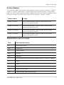
Product Names
This manual includes information for four products: Conext TL 8000 E, Conext TL 10000 E,
Conext TL 15000 E and Conext TL 20000 E photovoltaic grid tie inverters. The following
table lists the naming conventions used to differentiate information that only applies to one
of the four inverters. For information common to all products, “inverter” is used.
Product Name
Usage
Conext TL 8000 E
Information provided is specific to the 8 kVA Conext
photovoltaic grid tie inverter
Conext TL 10000 E
Information provided is specific to the 10 kVA Conext
photovoltaic grid tie inverter
Conext TL 15000 E
Information provided is specific to the 15 kVA Conext
photovoltaic grid tie inverter
Conext TL 20000 E
Information provided is specific to the 20 kVA Conext
photovoltaic grid tie inverter
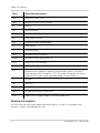
Abbreviations and Acronyms
Term
Definition/description
AC
Alternating Current
Cap
Capacitive
DC
Direct Current
GND
Ground
Ind
Inductive
ISC
Short circuit current rating of an PV panel under STC. (See STC, below.)
L1
Line 1
L2
Line 2
L3
Line 3
LCD
Liquid Crystal Display
LED
Light Emitting Diode (indicator light)
975-0609-01-01 Revision B
v
About This Manual
Term
Definition/description
MPP
Maximum Power Point
MPPT
Maximum Power Point Tracking
N
Neutral
OD
Outer Diameter
PE
Protective Earth (ground)
Pn
Real power nominal
PPE
Personal Protective Equipment
PV
Photovoltaic
Q
Reactive power
RCD
Residual Current Detection
RCMU
Residual Current Monitoring Unit
SELV
Safety Extra Low Voltage
Sn
Apparent power nominal
STC
Standard Test Conditions specific to photovoltaic panels (1000 W/m2,
light spectrum AM 1.5 and 25 °C [77 °F]); panel nameplate ratings are
based on STC and may be exceeded under some conditions.
U
Voltage
VAC
Volts AC
VDC
Volts DC
VMPP
Voltage at Maximum Power Point
VOC
Open circuit voltage rating of a PV panel under STC
Related Information
You can find more information about Schneider Electric, as well as its products and
services, at www.schneider-electric.com.
vi
975-0609-01-01 Revision B
About This Manual
Product Recycling
Do not dispose of this product with general household waste!
Electric appliances marked with the symbol shown must be
professionally treated to recover, reuse, and recycle materials, in order to
reduce negative environmental impact. When the product is no longer
usable, the consumer is legally obligated to ensure that is collected
separately under the local electronics recycling and treatment scheme.
975-0609-01-01 Revision B
vii
About This Manual
viii
975-0609-01-01 Revision B
Important Safety Instructions
READ AND SAVE THESE INSTRUCTIONS DO NOT DISCARD
This manual contains important safety instructions for Conext TL 8000 E, Conext TL 10000 E,
Conext TL 15000 E and Conext TL 20000 E photovoltaic grid tie inverters that must be
followed during the installation and maintenance of the inverter. Be sure to read, understand,
and save these safety instructions.
DANGER
HAZARD OF FIRE, ARC FLASH, OR ELECTRIC SHOCK FROM MULTIPLE
SOURCES
•
To be installed and serviced only by qualified personnel.
•
Before servicing, disconnect all sources and wait at least 1 minute.
Failure to follow these instructions will result in death or serious injury.
The term “qualified personnel” is defined on page iii of this manual. Personnel must be
equipped with appropriate PPE and follow safe electrical work practices. The inverter is
energized from the AC grid and up to four PV circuits. Before servicing the inverter or
accessing the communication module, disconnect all sources and wait at least 1 minute to
allow internal circuits to discharge. Operating the RID (Remote Inverter Disable) circuit or
the switch on the inverter does not remove all power from the inverter. Internal parts and the
external wiring remain live unless the PV and AC circuits have been disconnected
externally.
WARNING
LIMITATIONS ON USE
•
Do not use the inverter in connection with life support systems or other medical
equipment or devices.
•
Use the inverter only in grid-interconnected PV systems. The inverter does not
support off-grid, stand-alone, power backup function.
•
Persons with pacemakers must avoid coming in close proximity of this equipment.
Failure to follow these instructions can result in death or serious injury.
975-0609-01-01 Revision B
ix
Important Safety Instructions
WARNING
HAZARD OF ELECTRIC SHOCK, FIRE, AND EQUIPMENT DAMAGE
To prevent unsafe conditions and damage to the inverter, comply with the instructions
and the electrical, physical, and environmental installation specifications listed in this
manual.
Failure to follow these instructions can result in death or serious injury.
CAUTION
HAZARD OF BURN
The Conext Inverter heat sink could reach temperatures over 158 ºF (70 ºC) and can
cause skin burns if accidentally touched. Make sure the Conext Inverter is located away
from traffic areas.
Failure to follow these instructions can result in minor or moderate injury.
NOTICE
HAZARD OF EQUIPMENT DAMAGE
•
The inverter packaging box/carton has been provided with a shock watch sticker.
•
If the unit is received with the shock watch tripped, check if the inverter is damaged
before receiving it from the shipper.
•
Do not install or attempt to operate the inverter if it has been dropped or has
received more than cosmetic damage during transport or shipping. If the inverter is
damaged, or suspected to be damaged, contact Schneider Electric.
•
The inverter is designed and certified for full power operation at ambient
temperatures up to 40 °C (104 °F). Operation between 40 °C (104 °F) to 60 °C (140
°F) will result in reduced output power.
Failure to follow these instructions can result in damage to equipment.
x
975-0609-01-01 Revision B
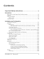
Contents
Important Safety Instructions - - - - - - - - - - - - - - - - - - - ix
Introduction
Description of the Conext Grid Tie Solar Inverter - - - - - - - - - - - - - - - - Features - - - - - - - - - - - - - - - - - - - - - - - - - - - - - - - - - - - - - - - - - - - - Physical Features - - - - - - - - - - - - - - - - - - - - - - - - - - - - - - - - - - - - - - Safety Label - - - - - - - - - - - - - - - - - - - - - - - - - - - - - - - - - - - - - - - Interface Panel - - - - - - - - - - - - - - - - - - - - - - - - - - - - - - - - - - - - - - - - -
1-2
1-2
1-3
1-6
1-8
Installation and Configuration
Installation Overview - - - - - - - - - - - - - - - - - - - - - - - - - - - - - - - - - - - - - 2-2
Planning - - - - - - - - - - - - - - - - - - - - - - - - - - - - - - - - - - - - - - - - - - - - - 2-2
PV Planning - - - - - - - - - - - - - - - - - - - - - - - - - - - - - - - - - - - - - - - - 2-2
Recommended Protection Devices and Conductor Sizing - - - - 2-4
PV Wiring Diagrams- - - - - - - - - - - - - - - - - - - - - - - - - - - - - - - - - - - 2-6
AC Grid Connection Planning - - - - - - - - - - - - - - - - - - - - - - - - - - - - 2-9
Recommended Protection Devices, Conductor Type and Sizing 2-9
Environmental Requirements - - - - - - - - - - - - - - - - - - - - - - - - - - - 2-10
Choosing the Right Location for Mounting - - - - - - - - - - - - - - - - - - 2-10
Unpacking - - - - - - - - - - - - - - - - - - - - - - - - - - - - - - - - - - - - - - - - - - - 2-12
Verify the Package Contents - - - - - - - - - - - - - - - - - - - - - - - - - - - 2-12
Unpack the Inverter - - - - - - - - - - - - - - - - - - - - - - - - - - - - - - - - - - 2-12
Check the Inverter - - - - - - - - - - - - - - - - - - - - - - - - - - - - - - - - - - - 2-14
Tools Required - - - - - - - - - - - - - - - - - - - - - - - - - - - - - - - - - - - - - 2-16
Views and Dimensions - - - - - - - - - - - - - - - - - - - - - - - - - - - - - - - - - - 2-17
Ventilation - - - - - - - - - - - - - - - - - - - - - - - - - - - - - - - - - - - - - - - - - - - 2-19
Mounting - - - - - - - - - - - - - - - - - - - - - - - - - - - - - - - - - - - - - - - - - - - - 2-20
Correct Mounting Position - - - - - - - - - - - - - - - - - - - - - - - - - - - - - 2-20
Mounting Plate - - - - - - - - - - - - - - - - - - - - - - - - - - - - - - - - - - - - - 2-22
Dimensions of the Mounting Plate - - - - - - - - - - - - - - - - - - - - 2-22
Correct Position of the Mounting Plate - - - - - - - - - - - - - - - - - 2-23
Fastening the Mounting Plate to the Wall- - - - - - - - - - - - - - - - 2-25
Mounting the Inverter - - - - - - - - - - - - - - - - - - - - - - - - - - - - - 2-28
Wiring - - - - - - - - - - - - - - - - - - - - - - - - - - - - - - - - - - - - - - - - - - - - - - 2-29
AC Wiring - - - - - - - - - - - - - - - - - - - - - - - - - - - - - - - - - - - - - - - - - 2-29
975-0609-01-01 Revision B
xi
Contents
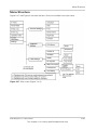
AC Plug Wiring - - - - - - - - - - - - - - - - - - - - - - - - - - - - - - - - - Maximum AC Cable Length - - - - - - - - - - - - - - - - - - - - - - - - Connecting the AC Plug - - - - - - - - - - - - - - - - - - - - - - - - - - DC Wiring (From PV Array) - - - - - - - - - - - - - - - - - - - - - - - - - - - - DC Wiring Polarity- - - - - - - - - - - - - - - - - - - - - - - - - - - - - - - Connection- - - - - - - - - - - - - - - - - - - - - - - - - - - - - - - - - - - - Earthing Terminal - - - - - - - - - - - - - - - - - - - - - - - - - - - - - - - - - - Communication Module - - - - - - - - - - - - - - - - - - - - - - - - - - - - - - - - Removing the Communication Module - - - - - - - - - - - - - - - - - - - Internal Data Logger - - - - - - - - - - - - - - - - - - - - - - - - - - - - - - - - - - - Connecting Cables to the Communication Module - - - - - - - - - - - RS485 Connection- - - - - - - - - - - - - - - - - - - - - - - - - - - - - - - - - - RS485 Connection Using the RJ-45 Connectors - - - - - - - - - RS485 Connection Using the 5-Position Terminal Block - - - - Termination Resistor - - - - - - - - - - - - - - - - - - - - - - - - - - - - - RID (Remote Inverter Disable) Input Connection - - - - - - - - - - - - Dry Contact Output Connection - - - - - - - - - - - - - - - - - - - - - - - - Remote Monitoring Services - - - - - - - - - - - - - - - - - - - - - - - - - - - - - Starting the Conext TL Inverters - - - - - - - - - - - - - - - - - - - - - - - - - - - Navigating the LCD Menus and Screens - - - - - - - - - - - - - - - - - - - - Selecting the Country - - - - - - - - - - - - - - - - - - - - - - - - - - - - - - - - - - Selecting the Language - - - - - - - - - - - - - - - - - - - - - - - - - - - - - - - - Menu Structure- - - - - - - - - - - - - - - - - - - - - - - - - - - - - - - - - - - - - - - Changing the Settings (Settings Menu)- - - - - - - - - - - - - - - - - - - - - - Setting the Date and Time - - - - - - - - - - - - - - - - - - - - - - - - - - - - Coefficient Settings Menu - - - - - - - - - - - - - - - - - - - - - - - - - - - - Install Settings Menu- - - - - - - - - - - - - - - - - - - - - - - - - - - - - - - - - - - Insulation Setting - - - - - - - - - - - - - - - - - - - - - - - - - - - - - - - - - - - RCMU Setting - - - - - - - - - - - - - - - - - - - - - - - - - - - - - - - - - - - - - DC Injection Setting - - - - - - - - - - - - - - - - - - - - - - - - - - - - - - - - - Grid System Setting - - - - - - - - - - - - - - - - - - - - - - - - - - - - - - - - - Grid Setting - - - - - - - - - - - - - - - - - - - - - - - - - - - - - - - - - - - - - - Active/Reactive Power Menu - - - - - - - - - - - - - - - - - - - - - - - - - - Setting the Active Power Control - - - - - - - - - - - - - - - - - - - - Setting the Frequency-Dependent Active Power Control- - - - - - - Setting the Reactive Power Control- - - - - - - - - - - - - - - - - - - Low Voltage Ride Through - - - - - - - - - - - - - - - - - - - - - - - - - - - - For Country setting “Italy”- - - - - - - - - - - - - - - - - - - - - - - - - - - - - Italy Selftest Menu - - - - - - - - - - - - - - - - - - - - - - - - - - - - - - - - - - -
xii
2-29
2-30
2-30
2-37
2-37
2-38
2-38
2-41
2-42
2-42
2-43
2-45
2-46
2-47
2-48
2-49
2-50
2-50
2-51
2-51
2-52
2-54
2-55
2-57
2-57
2-57
2-58
2-59
2-60
2-60
2-61
2-62
2-62
2-62
2-63
2-66
2-72
2-75
2-76
975-0609-01-01 Revision B
Contents
Exiting Technician or Service Mode Level of Security Access- - - - - - - 2-77
Restoring the Inverter to its Default Settings - - - - - - - - - - - - - - - - - - - 2-77
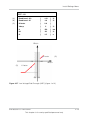
FRT settings for PO12.3 (Spain) on display - - - - - - - - - - - - - - - - - - - - 2-78
Operation
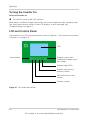
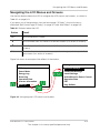
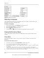
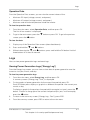
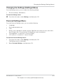
Turning the Inverter On - - - - - - - - - - - - - - - - - - - - - - - - - - - - - - - - - - LCD and Control Panel - - - - - - - - - - - - - - - - - - - - - - - - - - - - - - - - - - Navigating the LCD Menus and Screens - - - - - - - - - - - - - - - - - - - - - Indicator Light - - - - - - - - - - - - - - - - - - - - - - - - - - - - - - - - - - - - - - - - Home Page (E-Today)- - - - - - - - - - - - - - - - - - - - - - - - - - - - - - - - - - - Main Menu - - - - - - - - - - - - - - - - - - - - - - - - - - - - - - - - - - - - - - - - - - - Menu Structure- - - - - - - - - - - - - - - - - - - - - - - - - - - - - - - - - - - - - - - - Selecting a Language - - - - - - - - - - - - - - - - - - - - - - - - - - - - - - - - - - - Viewing Performance Values - - - - - - - - - - - - - - - - - - - - - - - - - - - - - - Power Meter - - - - - - - - - - - - - - - - - - - - - - - - - - - - - - - - - - - - - - - Operation Data - - - - - - - - - - - - - - - - - - - - - - - - - - - - - - - - - - - - - Logs - - - - - - - - - - - - - - - - - - - - - - - - - - - - - - - - - - - - - - - - - - - - - - - Viewing Power Generation Logs (“Energy Log”)- - - - - - - - - - - - - - Event Log - - - - - - - - - - - - - - - - - - - - - - - - - - - - - - - - - - - - - - - - - Inverter Information- - - - - - - - - - - - - - - - - - - - - - - - - - - - - - - - - - - - - Changing the Settings (Settings Menu)- - - - - - - - - - - - - - - - - - - - - - - Personal Settings Menu- - - - - - - - - - - - - - - - - - - - - - - - - - - - - - - - - - -
3-2
3-2
3-3
3-4
3-4
3-5
3-5
3-6
3-6
3-6
3-7
3-7
3-7
3-8
3-8
3-9
3-9
Troubleshooting
Messages - - - - - - - - - - - - - - - - - - - - - - - - - - - - - - - - - - - - - - - - - - - - 4-2
Preventive Maintenance
Periodic Maintenance - - - - - - - - - - - - - - - - - - - - - - - - - - - - - - - - - - - - 5-2
Semi-Annual Maintenance- - - - - - - - - - - - - - - - - - - - - - - - - - - - - - - - - 5-3
Specifications
System Specifications - - - - - - - - - - - - - - - - - - - - - - - - - - - - - - - - - - - Environmental Specifications - - - - - - - - - - - - - - - - - - - - - - - - - - - Electrical Specifications - - - - - - - - - - - - - - - - - - - - - - - - - - - - - - - RCMU - - - - - - - - - - - - - - - - - - - - - - - - - - - - - - - - - - - - - - - - - - - System Information and Communication Specifications - - - - - - - - Regulations and Directives- - - - - - - - - - - - - - - - - - - - - - - - - - - - - Dimensions - - - - - - - - - - - - - - - - - - - - - - - - - - - - - - - - - - - - - - - - - - Efficiency Curves - - - - - - - - - - - - - - - - - - - - - - - - - - - - - - - - - - - - - - -
975-0609-01-01 Revision B
A-2
A-2
A-3
A-4
A-5
A-6
A-6
A-7
xiii
Contents
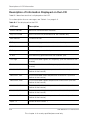
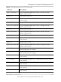
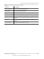
Descriptions of LCD Information
Description of Information Displayed on the LCD - - - - - - - - - - - - - - - - B-2
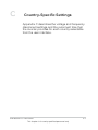
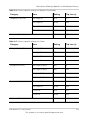
Country-Specific Settings
Description of Settings Specific to the Selected Country - - - - - - - - - - - C-2
Information About Your System - - - - - - - - - - - - - - - - - - - - D-1
Index - - - - - - - - - - - - - - - - - - - - - - - - - - - - - - - - - - - - - - - - - - - - E-1
xiv
975-0609-01-01 Revision B
Figures
Figure 1-1
Figure 1-2
Figure 1-3
Figure 1-4
Figure 1-5
Figure 1-6
Figure 1-7
Figure 1-8
Figure 2-1
Figure 2-2
Figure 2-3
Figure 2-4
Figure 2-5
Figure 2-6
Figure 2-7
Figure 2-8
Figure 2-9
Figure 2-10
Figure 2-11
Figure 2-12
Figure 2-13
Figure 2-14
Typical installation - - - - - - - - - - - - - - - - - - - - - - - - - - - - - - - 1–2
Block diagram Conext TL 8000 E, Conext TL 10000 E, Conext
15000 E and Conext 20000 E models - - - - - - - - - - - - - - - - - 1–4
Location of important physical features Conext TL 8000 E and
Conext TL 10000 E models - - - - - - - - - - - - - - - - - - - - - - - - - 1–5
Location of important physical features Conext TL 15000 E and
20000 E models - - - - - - - - - - - - - - - - - - - - - - - - - - - - - - - - - 1–6
Safety label - - - - - - - - - - - - - - - - - - - - - - - - - - - - - - - - - - - - 1–6
French UTE C 15-712-1 label (required for installations in France
only) - - - - - - - - - - - - - - - - - - - - - - - - - - - - - - - - - - - - - - - - - 1–7
Bottom of the inverter Conext TL 8000 E and Conext TL 10000 E
models - - - - - - - - - - - - - - - - - - - - - - - - - - - - - - - - - - - - - - - 1–8
Bottom of the inverter Conext TL 15000 E and Conext TL 20000 E
models - - - - - - - - - - - - - - - - - - - - - - - - - - - - - - - - - - - - - - - 1–9
Connection diagram Conext TL 8000 E and Conext TL 10000 E
models - - - - - - - - - - - - - - - - - - - - - - - - - - - - - - - - - - - - - - - 2–6
Connection diagram Conext TL15000 E and Conext TL 20000 E
models - - - - - - - - - - - - - - - - - - - - - - - - - - - - - - - - - - - - - - - 2–7
External DC disconnect switches- - - - - - - - - - - - - - - - - - - - - 2–8
AC connection details- - - - - - - - - - - - - - - - - - - - - - - - - - - - - 2–9
Lifting the inverter out of the crate Conext TL 8000 E and Conext
TL 10000 E models- - - - - - - - - - - - - - - - - - - - - - - - - - - - - - 2–13
Lifting the inverter out of the crate Conext TL15000 E and Conext
TL 20000 E models- - - - - - - - - - - - - - - - - - - - - - - - - - - - - - 2–14
Location of nameplate label Conext TL 8000 E and Conext TL
10000 E models - - - - - - - - - - - - - - - - - - - - - - - - - - - - - - - - 2–15
Location of nameplate label Conext TL15000 E and Conext TL
20000 E models - - - - - - - - - - - - - - - - - - - - - - - - - - - - - - - - 2–15
Views and dimensions Conext TL 8000 E and Conext TL 10000 E
models - - - - - - - - - - - - - - - - - - - - - - - - - - - - - - - - - - - - - - 2–17
Views and dimensions Conext 15000 E and Conext TL 20000 E
models - - - - - - - - - - - - - - - - - - - - - - - - - - - - - - - - - - - - - - 2–18
Airflow Conext TL 8000 E and Conext TL 10000 E models - - 2–19
Airflow Conext TL15000 E and Conext TL 20000 E models - 2–20
Correct mounting position - - - - - - - - - - - - - - - - - - - - - - - - - 2–21
Incorrect mounting positions - - - - - - - - - - - - - - - - - - - - - - - 2–21
975-0609-01-01 Revision B
xv
Figures
Figure 2-15
Figure 2-16
Figure 2-17
Figure 2-18
Figure 2-19
Figure 2-20
Figure 2-21
Figure 2-22
Figure 2-23
Figure 2-24
Figure 2-25
Figure 2-26
Figure 2-27
Figure 2-28
Figure 2-29
Figure 2-30
Figure 2-31
Figure 2-32
Figure 2-33
Figure 2-34
Figure 2-35
Figure 2-36
Figure 2-37
Figure 2-38
Figure 2-39
Figure 2-40
Figure 2-41
Figure 2-42
xvi
Proper installation distances Conext TL 8000 E, Conext TL10000
E, Conext TL15000 E and Conext TL 20000 E models - - - - - 2–22
Mounting plate dimensions - - - - - - - - - - - - - - - - - - - - - - - - 2–23
Position of mounting plate (rear view of the inverter) Conext TL
8000 E and Conext TL 10000 E models - - - - - - - - - - - - - - - 2–24
Position of mounting plate (rear view of the inverter) Conext
TL15000 E and Conext TL 20000 E models - - - - - - - - - - - - 2–25
Example of fastening the mounting plate to the wall Conext TL
8000 E and Conext TL 10000 E models - - - - - - - - - - - - - - - 2–26
Example of fastening the mounting plate to the wall Conext
TL15000 E and Conext TL 20000 E models - - - - - - - - - - - - 2–27
Location of mounting tabs (fastening the bottom of the inverter to
the wall) Conext TL 8000 E and Conext TL 10000 E models- 2–28
Location of mounting tabs (fastening the bottom of the inverter to
the wall) Conext TL 8000 E and Conext TL 20000 E models- 2–28
AC plug (exploded view) - - - - - - - - - - - - - - - - - - - - - - - - - 2–31
Increasing the inner diameter of the rubber insert - - - - - - - - 2–32
Sliding the cable nut and the back shell onto the cable - - - - 2–32
Stripping the wires - - - - - - - - - - - - - - - - - - - - - - - - - - - - - - 2–33
Plug wiring- - - - - - - - - - - - - - - - - - - - - - - - - - - - - - - - - - - - 2–34
Tightening the back shell - - - - - - - - - - - - - - - - - - - - - - - - - 2–35
Securing the AC cable - - - - - - - - - - - - - - - - - - - - - - - - - - - 2–35
Connecting the AC plug to the inverter and rotating the locking
ring - - - - - - - - - - - - - - - - - - - - - - - - - - - - - - - - - - - - - - - - - 2–36
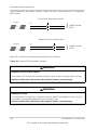
DC wiring polarity and connector types, for the array wiring- 2–38
Connecting the earthing conductor Conext TL 8000 E and Conext
TL 10000 E models- - - - - - - - - - - - - - - - - - - - - - - - - - - - - - 2–39
Connecting the earthing conductor Conext TL 15000 E and Conext
TL 20000 E models- - - - - - - - - - - - - - - - - - - - - - - - - - - - - - 2–40
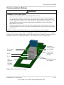
Communication module - - - - - - - - - - - - - - - - - - - - - - - - - - 2–41
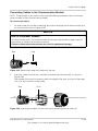
Removing a plug from the end of the seal - - - - - - - - - - - - - 2–43
Inserting the cables into the seal and assembling the claw and
seal- - - - - - - - - - - - - - - - - - - - - - - - - - - - - - - - - - - - - - - - - 2–43
Connecting the body of the cable gland, the claw and seal, and
the sealing nut - - - - - - - - - - - - - - - - - - - - - - - - - - - - - - - - - 2–44
RS485 wiring: multiple inverters- - - - - - - - - - - - - - - - - - - - - 2–45
RJ-45 Connectors - - - - - - - - - - - - - - - - - - - - - - - - - - - - - - 2–46
RS485 terminal block—pin numbering - - - - - - - - - - - - - - - - 2–47
Termination resistor—switch numbering- - - - - - - - - - - - - - - 2–48
Dry contact location - - - - - - - - - - - - - - - - - - - - - - - - - - - - - 2–50
975-0609-01-01 Revision B
Figures
Figure 2-43
Figure 2-44
Figure 2-45
Figure 2-46
Figure 2-47
Figure 2-48
Figure 2-49
Figure 2-50
Figure 2-51
Figure 2-52
Figure 2-53
Figure 2-54
Figure 2-55
Figure 2-56
Figure 2-57
Figure 2-58
Figure 2-59
Figure 2-60
Figure 3-1
Figure 3-2
Figure 3-3
Figure 3-4
Figure 3-5
Figure 5-1
Figure 5-2
Figure 5-3
Figure 5-4
Figure 5-5
Figure 5-6
Figure 5-7
Figure 5-8
Figure A-1
Navigating the LCD menus and screens - - - - - - - - - - - - - - 2–52
Select Country screen - - - - - - - - - - - - - - - - - - - - - - - - - - - 2–53
Select Language screen - - - - - - - - - - - - - - - - - - - - - - - - - - 2–54
Main menu- - - - - - - - - - - - - - - - - - - - - - - - - - - - - - - - - - - - 2–54
Main menu (figure 1 of 2) - - - - - - - - - - - - - - - - - - - - - - - - - 2–55
Main menu (figure 2 of 2) - - - - - - - - - - - - - - - - - - - - - - - - - 2–56
Power Limit - - - - - - - - - - - - - - - - - - - - - - - - - - - - - - - - - - - 2–63
Active power control- - - - - - - - - - - - - - - - - - - - - - - - - - - - - 2–64
Frequency-dependent active power control - - - - - - - - - - - - 2–65
Fixed power factor - - - - - - - - - - - - - - - - - - - - - - - - - - - - - - 2–66
Power factor (Constant cosφ) - - - - - - - - - - - - - - - - - - - - - - 2–67
cosφ(P) - - - - - - - - - - - - - - - - - - - - - - - - - - - - - - - - - - - - - - 2–68
Constant Reactive Power (Q) - - - - - - - - - - - - - - - - - - - - - - 2–69
Voltage (Q(U)) - - - - - - - - - - - - - - - - - - - - - - - - - - - - - - - - - 2–71
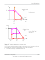
Low Voltage Ride Through (LVRT) (figure 1 of 2)- - - - - - - - - 2–73
Low Voltage Ride Through (LVRT) (figure 2 of 2)- - - - - - - - - 2–74
Low Voltage Ride Through (LVRT) (figure 1 of 2)- - - - - - - - - 2–76
FRD settings for Spain - - - - - - - - - - - - - - - - - - - - - - - - - - - 2–78
LCD and control panel - - - - - - - - - - - - - - - - - - - - - - - - - - - - 3–2
Navigating the LCD menus and screens - - - - - - - - - - - - - - - 3–3
Home page (E-Today) - - - - - - - - - - - - - - - - - - - - - - - - - - - - 3–4
Main menu- - - - - - - - - - - - - - - - - - - - - - - - - - - - - - - - - - - - - 3–5
Menu organization - - - - - - - - - - - - - - - - - - - - - - - - - - - - - - - 3–6
Loosening the screws of the fan bracket Conext TL 8000 E and
Conext TL 10000 E models - - - - - - - - - - - - - - - - - - - - - - - - - 5–3
Loosening the screws of the fan bracket Conext TL 15000 E and
Conext TL 20000 E models - - - - - - - - - - - - - - - - - - - - - - - - - 5–4
Disconnecting the fan connectors Conext TL 8000 E and Conext
TL 10000 E models- - - - - - - - - - - - - - - - - - - - - - - - - - - - - - - 5–4
Disconnecting the fan connectors Conext TL15000 E and Conext
TL 20000 E models- - - - - - - - - - - - - - - - - - - - - - - - - - - - - - - 5–5
Removing the fan bracket Conext TL 8000 E and Conext TL 10000
E models - - - - - - - - - - - - - - - - - - - - - - - - - - - - - - - - - - - - - - 5–6
Removing the fan bracket Conext TL15000 E and Conext TL 20000
E models - - - - - - - - - - - - - - - - - - - - - - - - - - - - - - - - - - - - - - 5–6
Removing the air outlet covers Conext TL 8000 E and Conext TL
10000 E models - - - - - - - - - - - - - - - - - - - - - - - - - - - - - - - - - 5–7
Removing the air outlet covers Conext TL15000 E and Conext TL
20000 E models - - - - - - - - - - - - - - - - - - - - - - - - - - - - - - - - - 5–8
Efficiency curves 8 kVA - - - - - - - - - - - - - - - - - - - - - - - - - - A–7
975-0609-01-01 Revision B
xvii
Figures
Figure A-2
Figure A-3
Figure A-4
xviii
Efficiency curves10 kVA - - - - - - - - - - - - - - - - - - - - - - - - - - A–7
Efficiency Curves 15 kVA - - - - - - - - - - - - - - - - - - - - - - - - - A–8
Efficiency curves 20 kVA- - - - - - - - - - - - - - - - - - - - - - - - - - A–8
975-0609-01-01 Revision B
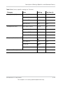
Tables
Table 2-1
Table 2-2
Table 2-3
Table 2-4
Table 2-5
Table 2-6
Table 2-7
Table 2-8
Table 2-9
Table 2-10
Table 3-1
Table 3-2
Table 4-1
Table A-1
Table A-2
Table A-3
Table A-4
Table B-1
Table C-1
Table C-2
Table C-3
Table C-4
Table C-5
Table C-6
Table C-7
Table C-8
Table C-9
Table C-10
Table C-11
Table C-12
Table C-13
Table C-14
Table C-15
Table C-16
Table C-17
Table C-18
Summary chart for PV input requirements- - - - - - - - - - - - - - - 2–4
Packing list - - - - - - - - - - - - - - - - - - - - - - - - - - - - - - - - - - - 2–12
IEC color-coding to identify the phase sequence
(phase rotation) - - - - - - - - - - - - - - - - - - - - - - - - - - - - - - - - 2–29
Maximum AC cable length - - - - - - - - - - - - - - - - - - - - - - - - 2–30
Internal Data Logger specifications - - - - - - - - - - - - - - - - - - 2–42
RS485 data format - - - - - - - - - - - - - - - - - - - - - - - - - - - - - - 2–46
RJ-45 pin definitions - - - - - - - - - - - - - - - - - - - - - - - - - - - - - 2–46
5-position terminal block pin definitions - - - - - - - - - - - - - - - 2–47
Termination resistor settings - - - - - - - - - - - - - - - - - - - - - - - 2–48
Buttons below the LCD - - - - - - - - - - - - - - - - - - - - - - - - - - - 2–51
Buttons below the LCD - - - - - - - - - - - - - - - - - - - - - - - - - - - - 3–3
Indicator light- - - - - - - - - - - - - - - - - - - - - - - - - - - - - - - - - - - 3–4
Alert message descriptions- - - - - - - - - - - - - - - - - - - - - - - - - 4–2
Environmental specifications - - - - - - - - - - - - - - - - - - - - - - - A–2
Electrical specifications - - - - - - - - - - - - - - - - - - - - - - - - - - A–3
System information and communication - - - - - - - - - - - - - - - A–5
Regulations and directives - - - - - - - - - - - - - - - - - - - - - - - - A–6
Text displayed on the LCD - - - - - - - - - - - - - - - - - - - - - - - - B–2
Lookup table for country settings- - - - - - - - - - - - - - - - - - - - C–2
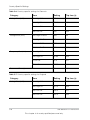
Country-specific settings for Australia - - - - - - - - - - - - - - - - C–3
Country-specific settings for Austria- - - - - - - - - - - - - - - - - - C–3
Country-specific settings for Belgium- - - - - - - - - - - - - - - - - C–4
Country-specific settings for Czech - - - - - - - - - - - - - - - - - - C–5
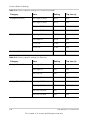
Country-specific settings for Denmark - - - - - - - - - - - - - - - - C–6
Country-specific settings for England- - - - - - - - - - - - - - - - - C–6
Country-specific settings for France- - - - - - - - - - - - - - - - - - C–7
Country-specific settings for Germany - - - - - - - - - - - - - - - - C–8
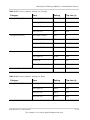
Country-specific settings for Greece - - - - - - - - - - - - - - - - - C–9
Country-specific settings for Ireland- - - - - - - - - - - - - - - - - C–10
Country-specific settings for Israel- - - - - - - - - - - - - - - - - - C–10
Country-specific settings for Italy- - - - - - - - - - - - - - - - - - - C–11
Country-specific settings for Netherlands - - - - - - - - - - - - - C–12
Country-specific settings for Portugal- - - - - - - - - - - - - - - - C–13
Country-specific settings for Spain - - - - - - - - - - - - - - - - - C–13
Country-specific settings for Spain - RD1699 - - - - - - - - - - C–14
Country-specific settings for Thailand - - - - - - - - - - - - - - - C–15
975-0609-01-01 Revision B
xix
xx
975-0609-01-01 Revision B
1
Introduction
Chapter 1, “Introduction” contains information
about the features and functions of Conext TL
8000 E, Conext TL 10000 E, Conext TL 15000 E
and Conext TL 20000 E photovoltaic grid tie
inverters.
975-0609-01-01 Revision B
This chapter is for use by qualified personnel only
1-1
Introduction
Description of the Conext Grid Tie Solar Inverter
The inverter converts DC power to AC power. It harvests solar energy from a PV array and
exports that energy directly to a three-phase electricity grid.
The inverter provides an option to collect the maximum available energy from the PV array
by constantly adjusting its output power to track the maximum power point (MPPT) of the
PV array. The inverter has two MPPT channels, so that two independent PV arrays, each
containing up to two paralleled inputs, can be connected to the inverter. Each PV array,
having one or two PV inputs, can be loaded to different peak power points, to capture the
maximum possible energy. The inverter can accommodate arrays with open circuit voltage
as high as 1000 VDC.
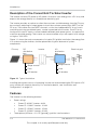
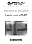
Figure 1-1 shows the major components of a typical PV grid-tie installation, the energy flow
in a system using the inverter, and the placement of typical balance-of-system
components.
PV array
DC
distribution
box
AC
distribution
box
Inverter
Electrical grid
3-phase
Surge arrestor
Surge arrestor
Fuse
Fuse
DC breaker
AC breaker
Figure 1-1 Typical installation
Installing the inverter consists of mounting it to the wall and connecting the DC input to a PV
array and the AC output to the utility. For installation details, see “Installation and
Configuration” on page 2–1.
Features
The inverter has the following features:
•
•
1-2
Power ratings:
•
Conext TL 8000 E inverter: 8 kVA
•
Conext TL 10000 E inverter: 10 kVA
•
Conext TL 15000 E inverter: 15 kVA
•
Conext TL 20000 E inverter: 20 kVA
Three-phase (3-Phase + N + PE [ground]), grid-tie, transformerless
975-0609-01-01 Revision B
This chapter is for use by qualified personnel only
Physical Features
•
•
Wide MPPT voltage range (350-850V)
RS485 (Modbus) communications
•
IP651 protection class for outdoor environments
•
•
•
•
•
DC (MC4) locking connectors
Included AC connector (IP67)
Integrated DC switch
Maximum power conversion efficiency: > 98%
European weighted power conversion efficiency:
•
Conext TL 8000 E inverter: 97.4%
•
Conext TL 10000 E inverter: 97.7%
•
Conext TL 15000 E inverter: 97.3%
•
Conext TL 20000 E inverter: 97.5%
Energy harvest (MPPT) efficiency: > 99%
Power factor adjustment range: 0.8 capacitive to 0.8 inductive
Low AC output current distortion (THD < 3%) @ rated power
Two independent MPP Trackers
Logs up to 30 events
5-inch (diagonally) graphical display (LCD) with integrated 4-key control panel
•
•
•
•
•
•
Physical Features
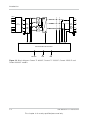
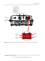
Figure 1-2 shows the block diagram of Conext TL 8000 E, Conext TL 10000 E, Conext TL
15000 E and Conext TL 20000 E inverters. Figure 1-3 and Figure 1-4 shows the locations of
important physical features of the inverter.
1. The IP65 enclosure is for electronics only; the balance of the enclosure is rated IP55 (for example, the ventilation cavity).
975-0609-01-01 Revision B
This chapter is for use by qualified personnel only
1-3
Introduction
'&
/
'&
&RQQHFWRU
'&
)LOWHU
$&
)LOWHU
9
9
/
/
1
3(
'&
&RPPXQLFDWLRQDQG&RQWURO
56
/&'
5,'
Figure 1-2 Block diagram Conext TL 8000 E, Conext TL 10000 E, Conext 15000 E and
Conext 20000 E models
1-4
975-0609-01-01 Revision B
This chapter is for use by qualified personnel only
Physical Features
LCD, indicator
light,
Control panel
(buttons)
Earthing
terminal
(near the side
of inverter)
Air outlets
AC connector
Safety label
Communication
connections
DC Connectors
Product
nameplate
label
DC switch
Fan assembly
Figure 1-3 Location of important physical features Conext TL 8000 E and Conext TL 10000
E models
975-0609-01-01 Revision B
This chapter is for use by qualified personnel only
1-5
Physical Features
LCD, indicator
light,
Control panel
(buttons)
AC connector
Earthing
terminal
(near the side
of inverter)
Air outlets
Communication
connections
(removable panel
to access)
Safety label
DC Connectors
DC switch
Product
nameplate label
Fan assembly
Figure 1-4 Location of important physical features Conext TL 15000 E and 20000 E models
Safety Label
The safety label is on the side of the inverter, as shown in Figure 1-3 and Figure 1-4. The
label is in English, and is shown in Figure 1-5. Figure 1-6 shows the French label.
DANGER
HAZARD OF FIRE, ARC FLASH,
OR ELECTRIC SHOCK FROM
MULTIPLE VOLTAGE SOURCES
7REHLQVWDOOHGDQGVHUYLFHGRQO\E\
TXDOLILHGSHUVRQQHO
>
5 min.
ThH CoQH[WTM IQYHUWHU LV HQHUJL]HG
fUom WZo VRXUFHV.%HfoUH RSHQLQg
FoYHU, GLVFRQQHFW DOO VRuUFHV of
SoZHU, DQG WhHQ ZDLWDWOHDVW ILYH
mLQXWHV foU LQWHUQDOFDSDFLWoUV Wo
GLVFhDUJH
Failure to follow these instructions
will result in death or serious injury.
Figure 1-5 Safety label
1-6
975-0609-01-01 Revision B
Physical Features
Figure 1-6 French UTE C 15-712-1 label (required for installations in France only)
In the event of installation in France, the device must be provided with the warning sticker
per UTE C 15-712-1. This warning label and instructions on where to affix the label
(document part # 976-0298-02-01) is included in the packaging.
975-0609-01-01 Revision B
This chapter is for use by qualified personnel only
1-7
Introduction
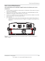
Interface Panel
The connectors are located on the bottom of the inverter, and are shown in Figure 1-7 and
Figure 1-8.
Communication:
Dry contact (1x)
Remote inverter disable
(1x)
RS485 (through RJ-45
[2x]) or terminal block(1x) DC switch
AC connector
Earthing
terminal
(1x)
Fan assembly (1)
String 1x
(DC2)
String 1x
(DC1)
String 2x
(DC2)
String 2x
(DC1)
Figure 1-7 Bottom of the inverter Conext TL 8000 E and Conext TL 10000 E models
1-8
975-0609-01-01 Revision B
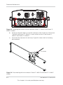
This chapter is for use by qualified personnel only
Interface Panel
Communication:
Dry contact (1x)
Remote inverter
disable (1x)
RS485 (through
RJ-45 [2x]) or
terminal block (1x)
DC switch
AC
connector
Earthing
terminal
(1x)
Fan assembly (4)
String 1x
(DC1)
String 2x
(DC1)
String 1x
(DC2)
String 2x
(DC2)
Figure 1-8 Bottom of the inverter Conext TL 15000 E and Conext TL 20000 E models
975-0609-01-01 Revision B
This chapter is for use by qualified personnel only
1-9
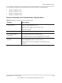
Introduction
The following table shows you which sections of this manual contain information related to
each item on the interface panel.
Item
See this section:
AC connector
“AC Wiring” on page 2–29
Communication connectors
“Communication Module” on page 2–41
DC switch
“Starting the Conext TL Inverters” on page 2–51
DC string connectors
“DC Wiring (From PV Array)” on page 2–37
Earthing terminal
“Earthing Terminal” on page 2–38
Fans
“Semi-Annual Maintenance” on page 5–3
1-10
975-0609-01-01 Revision B
This chapter is for use by qualified personnel only
2
Installation and Configuration
Chapter 2, “Installation and Configuration”
provides information and procedures for installing
and configuring the inverter.
975-0609-01-01 Revision B
This chapter is for use by qualified personnel only
2-1
Installation and Configuration
Installation Overview
DANGER
HAZARD OF ELECTRIC SHOCK
•
The installation procedures in this manual are for use only by qualified personnel.
•
The inverter must be installed and serviced only by qualified personnel equipped
with appropriate PPE.
Failure to follow these instructions will result in death or serious injury.
Planning
Planning for a system requires complete understanding of all the components that are
involved to successfully install the inverter for performance and reliability, and to meet
applicable installation codes.
Location
The inverter is rated and certified for both indoor and outdoor installation. See
“Environmental Requirements” on page 2–10.
Clearance
Adequate ventilation and service access should be considered when installing the inverter.
See “Environmental Requirements” on page 2–10.
Planning
This section provides information for you to consider before you install the inverter.
PV Planning
WARNING
HAZARD OF ELECTRIC SHOCK, FIRE, AND EQUIPMENT DAMAGE
The PV array voltage must never exceed 1000 VOC (open circuit voltage) under any
condition. The Absolute Maximum PV array ISC (short circuit current) must not exceed
the specified limit per MPP tracker under any conditions.
Failure to follow these instructions can result in death or serious injury, and
equipment damage.
2-2
975-0609-01-01 Revision B
This chapter is for use by qualified personnel only
Planning
A PV array sizing tool is available for download at http://www.schneider-electric.com/
products/ww/en/5300-solar-grid-tie-systems/5320-three-phase-solar/61160-conext-tl/ and
select Additional links to get to Sizing tool. This software is an optional tool to help match
the PV panel type and quantity to the inverter’s power rating.
WARNING
HAZARD OF ELECTRIC SHOCK
Use this inverter only with PV modules that have an IEC 61730 Class A rating.
Failure to follow these instructions can result in death or serious injury.
NOTICE
RISK OF EQUIPMENT DAMAGE
Do not ground either the positive or negative conductor from the PV array.
Failure to follow these instructions can result in equipment damage.
NOTICE
RISK OF EQUIPMENT DAMAGE
•
The maximum power of an array connected to DC1/DC2 must not exceed 5500 W
(for the Conext TL 8000 E inverter) or 7000 W (for the Conext TL 10000 E inverter).
• The maximum power of an array connected to DC1/DC2 must not exceed 8500 W
(for the Conext TL 15000 E inverter) or 11000 W (for the Conext TL 20000 E
inverter).
Failure to follow these instructions can result in equipment damage.
Make sure the following requirement is met:
•
Any components installed between the PV array and the inverter (for example, fuses,
breakers, wiring, and connectors) must be rated at least 1000 VDC and 1.25 times the
total array short circuit current nameplate rating (at STC) unless the applicable
installation codes require a higher multiplier.
975-0609-01-01 Revision B
This chapter is for use by qualified personnel only
2-3
Installation and Configuration
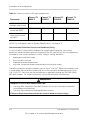
Table 2-1 Summary chart for PV input requirements
Conext TL
8000 E
Parameter
Conext TL
10000 E
Conext TL
15000 E
Conext TL
20000 E
Maximum input
voltage, open circuit
1000 VDC
Maximum input
current per MPPT
17 A
17 A
23 A
30 A
Absolute maximum
short circuit current
per MPPT
24A
24 A
30 A
30 A
NOTE: For more details refer to “System Specifications” on page A–2
Recommended Protection Devices and Conductor Sizing
It is the installer's responsibility to determine and provide the external over current
protection and disconnecting means required for the PV input wiring. You must determine
the need for over current protection, and its rating or setting, based on:
•
•
•
•
Applicable installation codes
Array currents involved
Expected ambient temperatures
Any other system parameters required by the installation codes
The MC4 connectors accept conductor sizes of 4 mm2 or 6 mm2. Select the conductor size
in accordance with installation codes and to limit the connector temperature to less than
105 °C (221 °F). You must use the manufacturer's required crimping tool PV-CZM-19100
(MC part number). For further information, contact the connector manufacturer.
WARNING
HAZARD OF ELECTRIC SHOCK AND FIRE
•
Use only MC4 connectors from Multi-Contact. Do not mix and match connectors
from different manufacturers.
• Use only the crimping tool required by Multi-Contact.
Failure to follow these instructions can result in death or serious injury.
2-4
975-0609-01-01 Revision B
This chapter is for use by qualified personnel only
Planning
Any cable or wiring located outdoors must be outdoor rated and UV (sunlight) resistant.
NOTICE
RISK OF EQUIPMENT DAMAGE
To ensure protection class IP65, to protect against penetrating moisture and dirt,
unused inputs and outputs must be properly closed with included caps.
Failure to follow these instructions can result in equipment damage.
975-0609-01-01 Revision B
This chapter is for use by qualified personnel only
2-5
Installation and Configuration
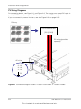
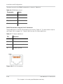
PV Wiring Diagrams
For connection details, see Figure 2-1 and Figure 2-2. The inverter can accept PV inputs in
parallel (1 MPP tracker) or separate PV input connections (2 MPP tracker).
If you are connecting several inverters, see also Figure 2-38 on page 2–45.
PV Array
DC Distribution box
[DC1] [DC2]
DC wiring (parallel or
separate)
AC wiring
1 - L1
2 - L2
3 - L3
4 - L4
-PE
Figure 2-1 Connection diagram Conext TL 8000 E and Conext TL 10000 E models
2-6
975-0609-01-01 Revision B
This chapter is for use by qualified personnel only
Planning
PV array
DC Distribution box
[DC1] [DC2]
DC wiring (Parallel or
separate)
AC wiring
1 - L1
2 - L2
3 - L3
4 - L4
-PE
Figure 2-2 Connection diagram Conext TL15000 E and Conext TL 20000 E models
975-0609-01-01 Revision B
This chapter is for use by qualified personnel only
2-7
Installation and Configuration
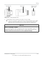
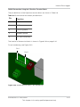
Install external DC disconnect switches. Figure 2-3 shows an example with 1 PV input per
MPP tracker.
External DC disconnect switch
Array 1
(+)
(-)
}
to MPP tracker
(DC1)
}
to MPP tracker
(DC2)
External DC disconnect switch
Array 2
(+)
(-)
Note: DC1 and DC2 can combine (parallel) up to 2 PV inputs.
Figure 2-3 External DC disconnect switches
z
WARNING
HAZARD OF ELECTRIC SHOCK
The inverter’s DC switch only switches off the inverter. It does not open the PV strings.
Failure to follow this instructions can result in death or serious injury.
WARNING
HAZARD OF FIRE
It is important to limit the flow of reverse current in the PV strings due to short circuit in
PV module, incorrect/damaged wiring or any other issue.
Failure to follow this instructions can result in death or serious injury.
2-8
975-0609-01-01 Revision B
This chapter is for use by qualified personnel only
Planning
AC Grid Connection Planning
This section describes requirements regarding the AC output wiring.
Recommended Protection Devices, Conductor Type and Sizing
It is the installer's responsibility to determine and provide the external over current
protection and disconnecting means required for the AC output wiring. You must determine
the rating or setting of the over current protection, and the size of the conductors used,
based on:
•
•
•
•
Applicable installation codes
Currents involved (see “Specifications” on page A–1)
Expected ambient temperatures
Any other system parameters required by the installation codes.
The AC cable must be jacketed and carry five insulated copper conductors to allow
connection to L1, L2, L3, N, and PE (protective earth). Any cable or wiring located outdoors
must be outdoor rated and UV (sunlight) resistant.
The AC connector provided is designed for AC cable outer diameters from 11 mm to
20 mm. The recommended AC cable diameter is 16 to 20 mm. The maximum cross
sectional area of the AC cables is 6.0 mm2 and the length of the cable shall be selected
appropriately to limit the voltage drop to <1%.
It is recommended to use twisted cables to reduce the grid line inductance and for
improved performance. If single core cables are used in open duct, keep the distance
between cores as minimum as possible.
AC 3-phase mains branch
Line 3 (L3)
Line 2 (L2)
Line 1 (L1)
To inverter AC plug
Neutral (N)
Ground (PE)
G
N
L1
L2
L3
Figure 2-4 AC connection details
Conext TL inverter supports TN-S, TN-C, TN-C-S and TT connection types (earthing
systems). It does not support IT connections.
975-0609-01-01 Revision B
This chapter is for use by qualified personnel only
2-9
Installation and Configuration
Environmental Requirements
See “Environmental Specifications” on page A–2.
•
The inverter’s enclosure can tolerate some ingress of dust; however, minimizing the
exposure to dust may extend the life of the inverter.
•
While the inverter’s IP65 enclosure1 protects the inverter from rain and water sprayed
at the inverter from a nozzle, it is recommended that outdoor installations be located
away from lawn sprinklers and other sources of spray such as a hose or pressure
washer.
The inverter is designed to operate in a -20 °C to 60 °C (-4 °F to 140 °F) ambient
environment. Optimal power harvest is achieved at ambient temperature between
-20 °C and 40 °C. Above 40 °C, power will derate.
•
Choosing the Right Location for Mounting
WARNING
HAZARD OF FIRE
Keep the area under and around the inverter clear of flammable material and debris.
Failure to follow these instructions can result in death or serious injury.
CAUTION
CRUSH HAZARD
•
The inverter weighs approximately 41 kg for 8 kVA and 10 kVA and 67 kg (148 lbs)
for 15 & 20 kVA. Ensure that the surface on which the inverter will be mounted, and
the mounting hardware used, are strong enough to support this weight.
• Use proper lifting techniques in accordance with local workplace safety rules, and
always use assistance when moving or lifting.
Failure to follow these instructions can result in moderate or minor injury, or
equipment damage.
1.The IP65 enclosure is for electronics only; the balance of the enclosure is rated IP55 (for example, the ventilation cavity).
2-10
975-0609-01-01 Revision B
This chapter is for use by qualified personnel only
Planning
NOTICE
RISK OF EQUIPMENT DAMAGE
•
The enclosure of the inverter protects internal parts from rain; however, outdoor
installations must be located away from lawn sprinklers and other sources of spray
such as a garden hose or a pressure washer.
• Direct sunlight on the inverter could raise internal temperatures, causing a reduction
of output power during hot weather. Where possible, install the inverter in an area
shaded from exposure to direct sunlight.
• Product performance might be impaired without adequate ventilation. Allow at least
600 mm (23.6 in.) clearance at the sides, top, and bottom of the inverter.
• Do not obstruct the air intakes and outlets.
Failure to follow these instructions can result in equipment damage.
975-0609-01-01 Revision B
This chapter is for use by qualified personnel only
2-11
Installation and Configuration
Unpacking
Before you install the inverter, perform the steps in this section.
Verify the Package Contents
Before you remove the inverter, verify that the package includes all the items listed in
Table 2-2.
Table 2-2 Packing list
Item
Quantity
Description
Inverter
1
Conext TL 8000 E (8 kVA), Conext TL 10000
E (10 kVA), Conext TL 15000 E (15 kVA) or
Conext TL 20000 E (20 kVA) inverter
Installation and operation
manual
1
This document
AC plug
1
Connector for AC connection
Mounting plate
1
Wall mounting plate to mount the inverter on
the wall
French label UTE C15-712-1*
1
Safety label for units to be sold in France
only. See Figure 1-6 on page 1–7
* Add UTE C15-712-1 Label if Unit is installed in France only.
Unpack the Inverter
CAUTION
CRUSH OR STRAIN HAZARD
• Use caution and correct procedures when lifting, moving, or mounting the inverter.
Failure to follow these instructions can result in death or serious injury, and
equipment damage.
NOTICE
RISK OF EQUIPMENT DAMAGE
If the unit is received with the shock watch on the packing box/carton tripped, check if
the inverter is damaged before receiving it from the shipper.
Failure to follow these instructions can result in equipment damage.
2-12
975-0609-01-01 Revision B
This chapter is for use by qualified personnel only
Unpacking
NOTICE
RISK OF EQUIPMENT DAMAGE
When removing the inverter, put it on cardboard, to prevent the back surface from
cosmetic damage.
Failure to follow these instructions can result in equipment damage.
To unpack the inverter:
◆
With the help of another person, carefully remove the inverter and place it on a flat
surface. See Figure 2-6.
Figure 2-5 Lifting the inverter out of the crate Conext TL 8000 E and Conext TL 10000 E
models
975-0609-01-01 Revision B
This chapter is for use by qualified personnel only
2-13
Installation and Configuration
Note: Remove the screws on the sides.
Figure 2-6 Lifting the inverter out of the crate Conext TL15000 E and Conext TL 20000 E
models
Check the Inverter
To check the inverter:
1.
2.
2-14
Check the inverter for damage from shipping. If it is damaged, contact Schneider
Electric.
Check the nameplate label on the inverter to make sure it is the model you ordered.
For the location of the label, see Figure 2-7 and Figure 2-8.
975-0609-01-01 Revision B
This chapter is for use by qualified personnel only
Unpacking
Location of nameplate
label
Figure 2-7 Location of nameplate label Conext TL 8000 E and Conext TL 10000 E models
Location of nameplate
label
Figure 2-8 Location of nameplate label Conext TL15000 E and Conext TL 20000 E models
3.
Fill in “Information About Your System” on page D–1.
975-0609-01-01 Revision B
This chapter is for use by qualified personnel only
2-15
Installation and Configuration
Tools Required
You will need the following tools to install the inverter.
❐
❐
❐
❐
❐
❐
❐
2-16
Slotted screwdriver
#2 Phillips screwdriver
Tools for preparing and connecting the wiring. See the user instructions from the
connectors’ manufacturers.
Wire stripper for AC wiring
Level for ensuring mounting bracket is straight
Adjustable wrench to tighten AC Cable nut
MC4 Connector removal tool
975-0609-01-01 Revision B
This chapter is for use by qualified personnel only
Views and Dimensions
Views and Dimensions
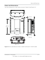
The views and dimensions of the inverter are shown in Figure 2-9 and Figure 2-10.
Top view
612 mm [24.1 in.]
262 mm
[10.3 in.]
625 mm
[24.6 in.]
Front view
278 mm
[10.9 in.]
Side view
Bottom view
Figure 2-9 Views and dimensions Conext TL 8000 E and Conext TL 10000 E models
975-0609-01-01 Revision B
This chapter is for use by qualified personnel only
2-17
Installation and Configuration
Top view
612 mm
[24.1 in.]
262 mm
[10.3 in.]
Front view
278 mm
[10.9 in.]
960 mm
[37.8 in.]
Side view
Bottom view
Figure 2-10 Views and dimensions Conext 15000 E and Conext TL 20000 E models
2-18
975-0609-01-01 Revision B
This chapter is for use by qualified personnel only
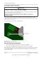
Ventilation
Ventilation
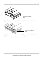
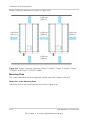
The air intakes are located on the bottom of the inverter, and the outlets are on the sides at
the top of the inverter, as shown in Figure 2-11 and Figure 2-12.
Figure 2-11 Airflow Conext TL 8000 E and Conext TL 10000 E models
975-0609-01-01 Revision B
This chapter is for use by qualified personnel only
2-19
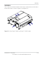
Installation and Configuration
Figure 2-12 Airflow Conext TL15000 E and Conext TL 20000 E models
Mounting
This section describes how to mount the inverter.
Correct Mounting Position
WARNING
HAZARD OF ELECTRIC SHOCK
Mount the inverter only upright (fan openings facing downward) and only on a vertical
surface.
Failure to follow these instructions can result in serious injury.
2-20
975-0609-01-01 Revision B
This chapter is for use by qualified personnel only
Mounting
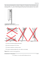
The correct mounting position is shown in Figure 2-13. Examples of incorrect positions are
shown in Figure 2-14. The inverter does not require any clearance at the rear and it may be
mounted flush on a surface. Install the device at eye level to ensure optimum user comfort.
Figure 2-13 Correct mounting position
(A)
(B)
(C)
(D)
(A) Inverter mounted hanging upside down
(B) Inverter mounted on flat surface
(C) Inverter mounted on slanting surface
(D) Inverter mounted upside down with cables on top edge
Figure 2-14 Incorrect mounting positions
975-0609-01-01 Revision B
This chapter is for use by qualified personnel only
2-21
Installation and Configuration
Proper installation distances are shown in Figure 2-15.
> 600 mm
[23.6 in.]
> 600 mm
[23.6 in.]
> 600 mm
[23.6 in.]
> 600 mm
[23.6 in.]
> 600 mm
[23.6 in.]
Figure 2-15 Proper installation distances Conext TL 8000 E, Conext TL10000 E, Conext
TL15000 E and Conext TL 20000 E models
Mounting Plate
This section describes the mounting plate used to mount the inverter to the wall.
Dimensions of the Mounting Plate
The dimensions of the mounting plate are shown in Figure 2-16.
2-22
975-0609-01-01 Revision B
This chapter is for use by qualified personnel only
Mounting
Side view
Wall
30 [1.2 in.]
193
[7.6 in.]
Six M6 screws appropriate for
the mounting surface
98 [3.8 in.]
30 [1.2 in.]
Six M6 screws appropriate for
the mounting surface
14 [0.6 in.]
Plan view
461 [18.1 in.]
82 * 5 [3.2 * 5 in.]
82
[3.2 in.]
Figure 2-16 Mounting plate dimensions
Correct Position of the Mounting Plate
The correct position of the mounting plate (in relation to the inverter) is shown in Figure 2-17
and Figure 2-18.
975-0609-01-01 Revision B
This chapter is for use by qualified personnel only
2-23
Installation and Configuration
Mounting plate
204 mm
[8 in.]
331 mm
[13 in.]
Figure 2-17 Position of mounting plate (rear view of the inverter) Conext TL 8000 E and
Conext TL 10000 E models
2-24
975-0609-01-01 Revision B
This chapter is for use by qualified personnel only
Mounting
Mounting plate
204 mm
[8 in.]
331 mm
[13 in.]
Figure 2-18 Position of mounting plate (rear view of the inverter) Conext TL15000 E and
Conext TL 20000 E models
Fastening the Mounting Plate to the Wall
To fasten the mounting plate to the wall:
1.
Select a wall or other suitable, solidly-built vertical surface capable of supporting the
weight of the inverter and the mounting plate.
2.
Using twelve M6 screws appropriate for the mounting surface you have chosen (for
example, wood, concrete, or brick), securely attach the mounting plate to the
mounting surface. An example of mounting on plywood, wallboard, and wall studs is
shown in Figure 2-20 on page 2–27.
Use level to ensure mounting plate is horizontal.
3.
975-0609-01-01 Revision B
This chapter is for use by qualified personnel only
2-25
Installation and Configuration
Side view
Wall stud
Wallboard
Plywood
(optional)
Mounting plate
1125 mm (44 in.) from floor puts the
inverter LCD at approx. 1060 mm
(41.7 in.) high.
1
Locate the wall studs.
2
If necessary, enhance the support surface with a plywood panel (at least 20 mm
[0.8 in.] thick) secured to the wall studs. Plywood should span three wall studs.
3
Use hardware sized to support a minimum of 70 kg (approximately 154 lbs) (not
supplied) to secure the plywood to the wall.
4
Using a level, secure the mounting plate to the wall. Use recommended
anchoring hardware to secure the plate.
Figure 2-19 Example of fastening the mounting plate to the wall Conext TL 8000 E and
Conext TL 10000 E models
2-26
975-0609-01-01 Revision B
This chapter is for use by qualified personnel only
Mounting
Side view
Wall stud
Wallboard
Plywood
(optional)
Mounting plate
1450 mm (57 in.) from floor puts the
inverter LCD at approx. 1060 mm
(41.7 in.) high.
1
Locate the wall studs.
2
If necessary, enhance the support surface with a plywood panel (at least 20 mm
[0.8 in.] thick) secured to the wall studs. Plywood should span three wall studs.
3
Use hardware sized to support a minimum of 70 kg (approximately 154 lbs) (not
supplied) to secure the plywood to the wall.
4
Using a level, secure the mounting plate to the wall. Use recommended
anchoring hardware to secure the plate.
Figure 2-20 Example of fastening the mounting plate to the wall Conext TL15000 E and
Conext TL 20000 E models
975-0609-01-01 Revision B
This chapter is for use by qualified personnel only
2-27
Installation and Configuration
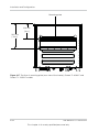
Mounting the Inverter
To mount the inverter:
1.
2.
Place the inverter on the mounting plate, making sure that the upper edge of the
mounting plate engages the flange on the back of the inverter.
Using two M6 screws appropriate for the mounting surface, fasten the bottom of the
inverter to the wall. For the location of the mounting tabs, see Figure 2-21 and
Figure 2-22.
Mounting tabs
Figure 2-21 Location of mounting tabs (fastening the bottom of the inverter to the wall)
Conext TL 8000 E and Conext TL 10000 E models
Mounting tabs
Figure 2-22 Location of mounting tabs (fastening the bottom of the inverter to the wall)
Conext TL 8000 E and Conext TL 20000 E models
2-28
975-0609-01-01 Revision B
This chapter is for use by qualified personnel only
Wiring
Wiring
This section describes how to connect the AC wiring (to the grid) and DC wiring (from the
PV array) to the inverter.
DANGER
HAZARD OF ELECTRIC SHOCK AND FIRE
•
•
All electrical work must be done in accordance with local electrical codes.
The Conext TL inverter has no user serviceable part inside. To be installed and
serviced only by qualified personnel equipped with appropriate PPE and following
safe electrical work practices.
• Before installation, de-energize the AC and PV sources using external
disconnecting means provided in the installation, and test using a meter rated at
least 1000 V AC and DC to make sure all circuits are de-energized. If possible,
follow a lock-out tag-out procedure.
• Do not connect PV conductors until the inverter is earthed either through the AC
connection or through the earthing terminal.
Failure to follow these instructions will result in death or serious injury.
AC Wiring
This section describes how to connect the inverter to the AC grid.
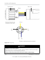
AC Plug Wiring
Many 3-phase AC distribution systems in Europe follow the IEC color-code to identify the
different conductors and the phase sequence (phase rotation). When in doubt, use a phase
rotation meter to verify.
Table 2-3 IEC color-coding to identify the phase sequence (phase rotation)
Component of AC wiring
Color
Line 1 (phase 1)
Brown
Line 2 (phase 2)
Black
Line 3 (phase 3)
Grey
Neutral
Blue
Protective earth
Green-yellow striped
975-0609-01-01 Revision B
This chapter is for use by qualified personnel only
2-29
Installation and Configuration
NOTICE
RISK OF EQUIPMENT DAMAGE
The inverter supports positive and negative phase sequences. The sequence of
L1 ~ L3 can be reversed; however, N and PE must be connected to the correct pins
regardless of phase sequence.
Failure to follow these instructions can result in equipment damage.
Maximum AC Cable Length
The following table provides recommended maximum cable lengths for a 6 mm² conductor
size from AC distribution box to inverter.
Table 2-4 Maximum AC cable length
Inverter
1% losses
2% losses
3% losses
Conext TL 8000 E
< 50 m
< 100 m
< 150 m
Conext TL 10000 E
< 30 m
< 60 m
< 90 m
Conext TL 15000 E
< 25 m
< 50 m
< 75m
Conext TL 20000 E
< 15 m
< 30 m
< 45 m
If the AC cable length exceeds 10 m, the use of an AC distribution box closer to the
inverter is recommended. For more information, refer to “AC Grid Connection Planning” on
page 2–9.
Connecting the AC Plug
To connect the AC plug:
1.
2-30
Separate the AC plug into three parts, as shown in Figure 2-23 on page 2–31.
a) Holding the middle (central) part of the female insert, rotate the back shell to
loosen it, and then detach it from the female insert.
b) Remove the cable nut (with rubber insert) from the back shell.
975-0609-01-01 Revision B
This chapter is for use by qualified personnel only
Wiring
Female insert
Back shell
Cable nut (with
rubber insert)
Figure 2-23 AC plug (exploded view)
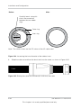
2.
If the diameter of the AC cable you are using is 16 mm or larger:
◆
Using a flat screwdriver, carefully break the connection between the two rubber
rings that make up the rubber insert, as shown in Figure 2-24 on page 2–32.
Discard the inner ring (to increase the inner diameter of the rubber insert).
NOTICE
RISK OF EQUIPMENT DAMAGE
If you have damaged the outer ring and the inverter will be used outdoors, obtain a
replacement rubber insert from Schneider Electric, and then repeat the above steps.
Failure to follow these instructions can result in equipment damage.
975-0609-01-01 Revision B
This chapter is for use by qualified personnel only
2-31
Installation and Configuration
Before:
After:
Carefully break, along this
circle, the connection
between the two rubber
rings.
Outer ring
Inner ring
20-16*
16-11*
Note: *The values shown are the OD values of the AC cable used
Figure 2-24 Increasing the inner diameter of the rubber insert
3.
Slide the cable nut and then the back shell onto the cable, as shown in Figure 2-25.
Cable
Figure 2-25 Sliding the cable nut and the back shell onto the cable
2-32
975-0609-01-01 Revision B
This chapter is for use by qualified personnel only
Wiring
4.
Using the appropriate tool, strip the wires:
DANGER
HAZARD OF ELECTRIC SHOCK
•
Make sure you do not accidentally cut the wire insulation and expose the wires
(other than the stripped ends).
• Make sure you follow the recommended specifications of stripping/trimming of the
wires.
Failure to follow these instructions will result in death or serious injury.
n
a)
Remove 55 mm (2.2 in.) of the outer jacket (shown in Figure 2-26).
Outer jacket
52.5 mm
[2.0 in.]
12 mm
[0.5 in.]
55 mm [2.2 in.] (PE)
Figure 2-26 Stripping the wires
b)
c)
5.
Trim all the wires, except the PE wire, to 52.5 mm (2.0 in.).
Using the appropriate tool, strip 12 mm (0.5 in.) of insulation from all wire ends,
as shown in Figure 2-26 (above).
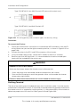
Insert the stripped end of each of the five wires into the appropriate hole in the female
insert, and then tighten each screw to 0.7 Nm (to hold each wire in place). See
Figure 2-27 on page 2–34.
975-0609-01-01 Revision B
This chapter is for use by qualified personnel only
2-33
Installation and Configuration
Female insert
Back shell
Screw
PE
L1
L2
L3
N
End view of female insert
(viewed from back shell)
PE (0*)
0
2
1
L2
(2*)
L1
(1*)
3
4
L3
(3*)
N
(4*)
* Numbers are embossed on the connector.
Figure 2-27 Plug wiring
DANGER
HAZARD OF ELECTRIC SHOCK
Make sure you do not mistakenly connect a phase conductor to the PE terminal (#0)—
otherwise the chassis will be energized at 230 VAC.
Failure to follow these instructions will result in death or serious injury.
2-34
975-0609-01-01 Revision B
This chapter is for use by qualified personnel only
Wiring
6.
7.
Slide the back shell towards the female insert.
Holding the middle (central) part of the female insert, rotate the back shell to connect
it to the female insert and then tighten it, as shown in Figure 2-28.
a) Hold this part.
b) Rotate clockwise to hand-tighten the back shell.
Cable
Figure 2-28 Tightening the back shell
8.
9.
Slide the cable nut towards the back shell.
Rotate the cable nut to secure the cable, as shown in Figure 2-29.
Rotate the cable nut clockwise to
secure the cable (tighten to 5 Nm)
Figure 2-29 Securing the AC cable
WARNING
HAZARD OF FIRE
To prevent damage to wire strands and their subsequent overheating, make sure you
properly install and tighten the cable nut onto the AC plug assembly.
Failure to follow these instructions can result in death or serious injury.
975-0609-01-01 Revision B
This chapter is for use by qualified personnel only
2-35
Installation and Configuration
NOTE: Make sure that the AC plug and cable are fully assembled before you connect them
to the inverter.
10. Connect the AC plug to the inverter, and then rotate the locking ring of the female
insert to secure the plug to the inverter. See Figure 2-30.
WARNING
HAZARD OF ELECTRIC SHOCK AND FIRE
Ensure the AC plug is properly connected with the locking ring tightened.
Failure to follow these instructions can result in death or serious injury.
NOTICE
RISK OF EQUIPMENT DAMAGE
Do not cross-thread the male and female connector. It can damage the connector if
cross-threaded.
Failure to follow these instructions can result in equipment damage.
Inverter
Rotate clockwise to hand-tighten.
Figure 2-30 Connecting the AC plug to the inverter and rotating the locking ring
11. Using insulated cable clamps, secure the cable to the wall or structure.
2-36
975-0609-01-01 Revision B
This chapter is for use by qualified personnel only
Wiring
WARNING
HAZARD OF ELECTRIC SHOCK
Make sure the clamp nearest the inverter is at a distance that:
•
•
Allows the AC plug to be connected and disconnected from the inverter.
Does not allow the AC plug to reach the ground or other surface under the inverter
where water might collect.
Failure to follow these instructions can result in death or serious injury.
DC Wiring (From PV Array)
WARNING
HAZARD OF ELECTRIC SHOCK AND FIRE
•
Use only MC4 connectors from Multi-Contact. Do not mix and match connectors
from different manufacturers.
• Use only the crimping tool (MC part # PV-CZM-19100) required by Multi-Contact.
• Do not disconnect MC4 connectors under load.
Failure to follow these instructions can result in death or serious injury.
DC Wiring Polarity
NOTICE
RISK OF EQUIPMENT DAMAGE
•
•
Make sure the correct polarity is used for all power connections.
In case of reverse polarity of DC, there is a protection by diode. There is no damage
involved for the inverter. The array will be shorted: No DC voltage on the MPPT input
and the PV generator will be in short circuit condition.
• Do not ground either the (+) or the (-) conductor of the PV array.
Failure to follow these instructions can result in equipment damage.
The PV wiring connects to the inverter using polarized connectors. The polarity of the
connectors to be used on the wiring to the inverter is shown in Figure 2-31. Your inverter
has the correct connectors to mate with the connectors shown.
975-0609-01-01 Revision B
This chapter is for use by qualified personnel only
2-37
Installation and Configuration
Type: PV-KBT4/6 II, from Multi-Contact AG (www.multi-contact.com)
+
Type: PV-KST4/6 II, from Multi-Contact AG
Figure 2-31 DC wiring polarity and connector types, for the array wiring
Connection
To connect the PV wires:
1.
2.
3.
4.
Follow the manufacturer’s instructions to assemble the MC4 connectors onto the PV
wiring. Make sure you use the right connector polarities, as shown in Figure 2-31 on
page 2–38.
Connect the wires to the DC1 and DC2 connectors of the inverter.
Using insulated cable clamps, secure the PV cables to the wall or structure.
Remove caps from MC4 terminals. It is recommended to close the unused open
inputs with the included MC4 terminal caps.
WARNING
HAZARD OF ELECTRIC SHOCK
Make sure the clamps nearest the inverter are at a distance that:
•
•
Allows the plugs to be connected and disconnected from the inverter.
Does not allow the plugs to reach the ground or other surface under the inverter
where water might collect.
Failure to follow these instructions can result in death or serious injury.
Earthing Terminal
The use of this earthing terminal depends upon local installation codes. It can be used to
connect the PV metalwork to earth, or to provide a second protective ground connection for
the inverter chassis as required by some countries. It is the responsibility of the installer to
determine proper use of this terminal. See Figure 2-32 and Figure 2-33.
2-38
975-0609-01-01 Revision B
This chapter is for use by qualified personnel only
Wiring
NOTE: Use 2.5 mm2 earthing conductor for Conext TL 8000 E and Conext TL 10000 E and
a 6 mm2 earthing conductor for Conext TL 15000 E and Conext TL 20000 E.
WARNING
HAZARD OF ELECTRIC SHOCK
If the PV metalwork grounding is done at the inverter, removal of the inverter or
disconnection of the AC plug from the inverter will leave the PV metalwork not grounded;
you must provide temporary additional grounding.
Failure to follow these instructions can result in death or serious injury.
N
B
A
C
A:
Earthing terminal
B:
Star washer
C:
M6 screw with captive
plain and spring
washer
Earthing conductor
Figure 2-32 Connecting the earthing conductor Conext TL 8000 E and Conext TL 10000 E
models
975-0609-01-01 Revision B
This chapter is for use by qualified personnel only
2-39
Installation and Configuration
A
B
C
A:
Earthing terminal
B:
Star washer
C:
M6 screw with
captive plain and
spring washer
Earthing conductor
Figure 2-33 Connecting the earthing conductor Conext TL 15000 E and Conext TL 20000
E models
2-40
975-0609-01-01 Revision B
This chapter is for use by qualified personnel only
Communication Module
Communication Module
WARNING
HAZARD OF ELECTRIC SHOCK
•
•
Connect only to Safety Extra Low Voltage (SELV) circuits.
The circuits provided for use with external communications and control equipment
are designed to provide isolation from neighbouring hazardous circuits within the
inverter. The communications and control circuits are classified as Safety Extra Low
Voltage (SELV) and must only be connected to other SELV circuits of the types
described in this manual.
• Physical and electrical separation of the communications and control circuits from
non-SELV electrical circuits must be maintained both within the inverter and outside
the inverter.
Failure to follow these instructions can result in death or serious injury.
The communication module supports the Modbus communication protocol via an RS485
interface. The module also provides an RID (Remote Inverter Disable) input and a dry (not
energized) contact for signalling purposes. The module is shown in Figure 2-34.
5-position
terminal block
(for RS485)
Dry contact
terminals
Termination
resistor (for
RS485)
Pin 8
Pin 1
RJ-45 connectors
(for RS485)
RID
(Remote
Inverter
Disable)
terminals
Figure 2-34 Communication module
975-0609-01-01 Revision B
This chapter is for use by qualified personnel only
2-41
Installation and Configuration
Removing the Communication Module
DANGER
HAZARD OF ELECTRIC SHOCK AND FIRE
•
•
All electrical work must be done in accordance with local electrical codes.
The Conext TL inverter has no user serviceable parts inside. To be installed and
serviced only by qualified personnel equipped with appropriate PPE and following
safe electrical work practices.
• Before installation, de-energize the AC and PV sources using external
disconnecting means provided in the installation, and test using a meter rated at
least 1000 V AC and DC to make sure all circuits are de-energized. If possible,
follow a lock-out tag-out procedure.
• Do not connect PV conductors until the inverter is earthed either through the AC
connection or through the earthing terminal.
Failure to follow these instructions will result in death or serious injury.
To remove the communication module:
1.
2.
3.
4.
5.
Turn the DC switch to the “OFF” position. For the switch location, see Figure 1-8 on
page 1–9.
Wait at least 1 minute for internal voltages to discharge, and then disconnect the AC
plug and all PV connectors from the inverter, being careful not to allow water or dirt to
contact any of connectors.
Remove the two screws—one on each side of the connector labeled “RS485” (above
the second fan on the interface panel). For the connector location, see Figure 1-8 on
page 1–9.
Pull the cover off.
Remove the communication module.
Internal Data Logger
Table 2-5 Internal Data Logger specifications
Recording Cycle
Storage Time
1 record/5 minute
1 day
1 record/15 minutes
1 month
1 record/1 day
1 year
1 record/1 month
10 years
2-42
975-0609-01-01 Revision B
This chapter is for use by qualified personnel only
Internal Data Logger
Connecting Cables to the Communication Module
NOTE: The drawings in this section show one cable being connected. You can connect
several cables to the communication module.
To connect the cables:
1.
For each cable you will be connecting, pull one of the plugs out of the end of the seal,
as shown by the arrow in Figure 2-35.
NOTICE
RISK OF EQUIPMENT DAMAGE
To make sure the seal is not compromised, remove only the number of plugs equal to
the number of cables you will be connecting.
Failure to follow these instructions can result in equipment damage.
Seal
Plug
Figure 2-35 Removing a plug from the end of the seal
2.
Insert the cables into the seal, and then assemble the claw and seal, as shown in
Figure 2-36.
The outside of the seal has one cut, down the length of the seal, for each of the plugs.
This is for easy insertion of the cable.
Seal
Claw
1.
2.
Figure 2-36 Inserting the cables into the seal and assembling the claw and seal
975-0609-01-01 Revision B
This chapter is for use by qualified personnel only
2-43
Installation and Configuration
3.
4.
For each cable, leave 100 to 170 mm (3.9 to 6.7 in.) from the end of the cable to the
seal. This is to provide enough cable to reach the connector on the communication
module when the module is inserted in the inverter.
Connect the body of the cable gland to the claw and seal, as shown in the left part of
Figure 2-37.
Body of the cable gland
Claw and seal
Sealing nut
Figure 2-37 Connecting the body of the cable gland, the claw and seal, and the sealing
nut
5.
6.
7.
8.
2-44
Slide the sealing nut towards the body of the cable gland with claw and seal (as
shown in the right part of Figure 2-37), and then hand-tighten the sealing nut onto the
body.
Connect the end of each cable to the appropriate connector on the communication
module.
Insert the communication module into the inverter.
Attach the cover of the communication module slot to the inverter. Tighten each of the
two captive screws to 0.7 Nm.
975-0609-01-01 Revision B
This chapter is for use by qualified personnel only
Internal Data Logger
RS485 Connection
NOTICE
RISK OF EQUIPMENT DAMAGE
Make sure the other end of the RS485 connection is also RS485. Connection to any
other type of communication port, such as Ethernet, may result in equipment damage.
Failure to follow these instructions can result in equipment damage.
Two options are available for implementing the RS485 connection:
•
•
Using either or both of the two RJ-45 connectors. See the following section “RS485
Connection Using the RJ-45 Connectors” on page 2–46.
Using the 5-position terminal block. See “RS485 Connection Using the 5-Position
Terminal Block” on page 2–47.
NOTE: Use Category 5 shielded twisted pair cable AWG 24 with one twisted pair and at
least a third conductor.
The wiring when using multiple inverters is shown in Figure 2-38.
Termination resistor must be OFF.
Inverter 1
Inverter n
Inverter 2
Termination
resistor
must be
ON.
Termination
resistor must be
across DATA+ to
DATA- (120Ω)
RS485/USB
or
RS485/RS232
Note: Number of inverters connected in parallel is recommended to be limited to 32.
Figure 2-38 RS485 wiring: multiple inverters
975-0609-01-01 Revision B
This chapter is for use by qualified personnel only
2-45
Installation and Configuration
The data format for the RS485 connection is shown in Table 2-6.
Table 2-6 RS485 data format
Parameter
Value
Baud rate
9600
Data bits
8
Stop bits
1
Parity
None
RS485 Connection Using the RJ-45 Connectors
The pin definitions of the RJ-45 connection are shown in Table 2-7. For the location of pin 8,
see Figure 2-34 on page 2–41. Figure 2-39 illustrates RJ-45 pin definitions.
Table 2-7 RJ-45 pin definitions
Pin
Function
4
DATA+
5
DATA-
7
NC (Not connected)
8
Modbus ground
Figure 2-39 RJ-45 Connectors
2-46
975-0609-01-01 Revision B
This chapter is for use by qualified personnel only
Internal Data Logger
RS485 Connection Using the 5-Position Terminal Block
The pin definitions of the 5-position terminal block are shown in Table 2-8.
Table 2-8 5-position terminal block pin definitions
Pin
Function
1
DATA+
2
DATA-
3
Chassis ground
4
Modbus ground
5
NC (Not connected)
The location of the terminal block is shown in Figure 2-34 on page 2–41.
For pin numbering, see Figure 2-40.
Pin 1
Pin 5
Figure 2-40 RS485 terminal block—pin numbering
975-0609-01-01 Revision B
This chapter is for use by qualified personnel only
2-47
Installation and Configuration
Termination Resistor
If the inverter is the first or the last device of the RS485 chain, set the termination resistor to
on; otherwise, set it to off. The location of the termination resistor is shown in Figure 2-41.
The settings are shown in Table 2-9.
Switch 2
Switch 1 (both switches are shown in the OFF position)
Termination resistor
Figure 2-41 Termination resistor—switch numbering
Table 2-9 Termination resistor settings
Switch 1
Switch 2
Result
Off
Off
The termination resistor is off.
Off
On
The termination resistor is on.
On
Off
The termination resistor is on.
On
On
The termination resistor is on.
2-48
975-0609-01-01 Revision B
This chapter is for use by qualified personnel only
Internal Data Logger
RID (Remote Inverter Disable) Input Connection
The inverter has one optional Remote Inverter Disable (RID) connection available from a
two-terminal screw terminal block. This input is intended to be connected to dry (non-energized) switch or relay contacts. The external contacts must be capable of switching 30 mA
at 12 VDC. The location of the RID connection is shown in Figure 2-34 on page 2–41.
NOTE: On the communication module, the RID connection is labelled as “EPO”.
During inverter operation, these pins are normally not connected together. With the RID
feature, connecting these pins together (by the use of a remote contact, such as a relay or
switch) causes the internal AC power contactors of the inverter to open and the inverter to
shut down.
WARNING
HAZARD OF ELECTRIC SHOCK
Do not remove any covers. Operating the RID (Remote Inverter Disable) circuit or the
switch on the inverter does not remove all power from the inverter. Internal parts and the
external wiring remain live unless the PV and AC circuits have been disconnected
externally.
Failure to follow these instructions can result in death or serious injury.
If you do not want to use the RID feature, do not connect anything to the RID terminals. This
will leave the inverter operating normally, controlled by the DC switch of the inverter, by the
inverter controls, and by RS485 communication.
NOTICE
RISK OF EQUIPMENT DAMAGE
Limit the RID wire length to less than 30 m (98 ft).
Failure to follow these instructions can result in equipment damage.
At some installations, a nearby lightning strike may induce a surge current in the RID wiring
large enough to damage the internal circuit. Limiting the wire length will reduce this risk.
975-0609-01-01 Revision B
This chapter is for use by qualified personnel only
2-49
Installation and Configuration
Dry Contact Output Connection
WARNING
HAZARD OF SHOCK. RISK OF EQUIPMENT DAMAGE.
Do not connect circuits exceeding 28 VDC and 3 A to the dry contact output. Use of a
3 A/32 VDC certified fuse is recommended.
Failure to follow these instructions can result in death, serious injury, or
equipment damage.
One set of dry contact connections is provided to give a remote indication of inverter
status. When the inverter is operating normally, the contact is closed. If the inverter is not
operating, the contact is open.
For the location of the connection, see Figure 2-42.
Dry contact
Figure 2-42 Dry contact location
Remote Monitoring Services
•
•
Web Log: Data logger by MeteoControl. Connection via RS485.
Solar Log: Data logger by Solare Datensysteme. Connection via RS485.
When MeteoControl and Solar log dataloggers are used, data is imported from the inverters
via an RS485 interface. For more information refer to the operations instructions of the
particular data logger.
2-50
975-0609-01-01 Revision B
This chapter is for use by qualified personnel only
Starting the Conext TL Inverters
Starting the Conext TL Inverters
Start up procedure:
1.
2.
3.
4.
5.
6.
7.
8.
9.
Ensure that the external PV and AC disconnection means are de-energized before
starting the inverter.
Make sure the AC wiring and DC wiring have been completed. See “AC Plug Wiring”
on page 2–29 and “DC Wiring (From PV Array)” on page 2–37.
Make sure the cover of the communication module slot is back in place.
Replace the cover on the wiring box.
Ensure all the MC4 connectors are properly locked.
Turn ON the external AC and DC disconnect switches.
Turn the DC switch to the “ON” position. For the switch location, see Figure 1-8 on
page 1–9.
Check the status of the indicator light (LED; see Table 3-2 on page 3–4). The LED
should be solid green.
If the LED is not solid green, check that:
•
All the connections are correct.
•
All external disconnect switches are closed.
•
The DC switch of the inverter is in the “ON” position.
Navigating the LCD Menus and Screens
Use the four buttons below the LCD to navigate the LCD menus and screens, as shown in
Table 2-10.
Table 2-10 Buttons below the LCD
Button
Result
ESC
Go to the previous screen.
▼
Go to the next item in a menu or to the next screen (in a series of screens).
▲
OK
Go to the previous item in a menu or to the previous screen (in a series of
screens).
Executes the selected menu item, accepts the changes, or takes you to the
next screen (in a series of screens).
975-0609-01-01 Revision B
This chapter is for use by qualified personnel only
2-51
Installation and Configuration
Figure 2-43 shows an example of the effects of the buttons.
Menu
Settings
E-Today
Personal Settings
Power Meter
Energy Log
Event Log
Operation Data
Inverter Information
Settings
Coefficient Settings
Install Settings
Active/Reactive Power Control
Operation Data
FRT
Italy Selftest
Figure 2-43 Navigating the LCD menus and screens
Selecting the Country
The first time the inverter is energized and turned on, the Select Country screen is
displayed. The window is shown in Figure 2-44. (To display this screen at a later time, use
the technician password to access the Install Settings menu, as described in “Install
Settings Menu” on page 2–58, select Country/Grid, and then press OK. Select Country/
System, and then press OK.)
NOTE: For information on specific approvals that the inverters have, see Appendix A,
“Regulations and Directives” on page A–6.
WARNING
HAZARD OF ELECTRIC SHOCK
•
•
The selected country code can only be changed by qualified personnel.
Ensure that local grid code selections are properly made before installing the
inverter.
Failure to follow these instructions can result in death or serious injury.
2-52
975-0609-01-01 Revision B
This chapter is for use by qualified personnel only
Selecting the Country
Select Country
21. Jun 2010 13:50
Australia
Austria
Belgium
Bulgaria
China
Czech
Figure 2-44 Select Country screen
The country selection sets specific parameters for protection and other features, according
to country-specific requirements. For a listing of settings contained in each country
selection, see Appendix C, “Country-Specific Settings”.
To specify the country:
1.
Use the
▼
▲
and
buttons to select the country, and then press OK.
Custom: Select this value if you want to change the Grid Setting. See “Grid
Setting” on page 2–62.
In the Confirm Country screen, press OK to confirm your selection, or press ESC to go
to the previous screen.
After you press OK, the Select Language screen is displayed.
•
2.
975-0609-01-01 Revision B
This chapter is for use by qualified personnel only
2-53
Installation and Configuration
Selecting the Language
In the Select Language screen you can specify what language is used in all of the screens,
as shown in Figure 2-45.
Select Language
21. Jun 2010 13:50
English
Deutsch
Français
Italiano
Español
Nederlands
Figure 2-45 Select Language screen
To specify the language:
◆
Use the
▼ and ▲ buttons to select the language, and then press OK.
After you have set the language, the main menu is displayed in the selected language, as
shown in Figure 2-46.
Menu
21. Jun 2010 13:50
E-Today
Power Meter
Energy Log
Event Log
Operation Data
Inverter Information
Settings
Figure 2-46 Main menu
2-54
975-0609-01-01 Revision B
This chapter is for use by qualified personnel only
Menu Structure
Menu Structure
Figure 2-47 and Figure 2-48 show the items that are available from each menu.
Figure 2-47 Main menu (figure 1 of 2)
975-0609-01-01 Revision B
This chapter is for use by qualified personnel only
2-55
Installation and Configuration
Figure 2-48 Main menu (figure 2 of 2)
2-56
975-0609-01-01 Revision B
This chapter is for use by qualified personnel only
Changing the Settings (Settings Menu)
Changing the Settings (Settings Menu)
From the Settings menu, adjust the following settings or perform these tests:
•
•
•
•
•
•
Personal settings. See the next section, “Setting the Date and Time.”
Coefficients settings. See page 2–57.
Install settings. See page 2–58.
Active/reactive power control settings. See page 2–62.
Low voltage ride through. See page 2–72.
Italy selftest (available only if the Country setting is “Italy”; for more information, see
“Selecting the Country” on page 2–52). For more information on Italy selftest, see
page 2–76.
To view the Settings menu:
◆
From the main menu, select Settings, and then press OK.
Setting the Date and Time
To set the date and time:
1.
2.
Display the Settings menu as described above.
Select Personal Settings, and then press OK.
3.
Use the
4.
▼ button to select the Date, and then press OK.
Use the ▼ and ▲ buttons to adjust the date, month, and year; press OK to move
from date to month to year. Once done, press OK.
5.
Use the
OK.
▼ and ▲ buttons to adjust the time (hour and minutes). Once done, press
Coefficient Settings Menu
From the Coefficient Settings menu, you can set the following:
•
CO2 Saved: Amount of CO2 (in kg) generated when producing, from non-renewable
energy sources, 1 kWh. This coefficient is used to approximate and display, in the
Power Meter and Energy Log screens, the reduction of CO2 production as a result of
using the inverter.
To view the Coefficient Settings menu:
1.
From the main menu, select Settings, and then press OK.
The Settings menu is displayed.
2.
Select Coefficient Settings, and then press OK.
975-0609-01-01 Revision B
This chapter is for use by qualified personnel only
2-57
Installation and Configuration
Install Settings Menu
WARNING
HAZARD OF ELECTRIC SHOCK AND FIRE
Some settings available in the Install Settings menu and submenus are related to safety
functions and must only be adjusted by authorized personnel aware of the impact of
changing the settings, and only with the agreement of the local authority.
Failure to follow these instructions can result in death or serious injury.
From the Install Settings menu, you can configure these settings:
•
•
•
•
•
•
•
Inverter ID: Used to distinguish each inverter if you have several of them installed.
Insulation: See “Insulation Setting” on page 2–59.
RCMU: See “RCMU Setting” on page 2–60.
DC Injection: See “DC Injection Setting” on page 2–60.
Return to Factory: See “Restoring the Inverter to its Default Settings” on page 2–77.
Country/Grid: See “Grid System Setting” on page 2–61.
Grid Setting: See “Grid Setting” on page 2–62.
To display the Install Settings menu:
1.
2.
From the main menu, select Settings, and then press OK.
Select Install Settings, and then press OK.
3.
and
buttons to set each of the four digits in the password. Press OK
Use the
after each digit is entered, and then press OK.
Two types of passwords are available:
•
Technician password: Gives access to some items that are hidden from the dayto-day user of the inverter.
•
Service mode: Gives access to all the items that are accessed using the
technician password and additionally gives access to this menu item:
•Return to Factory
If you require these access levels and do not know the passwords, contact Schneider
Electric. The passwords will be provided only to qualified installers and service
personnel.
2-58
▼
▲
975-0609-01-01 Revision B
This chapter is for use by qualified personnel only
Install Settings Menu
Insulation Setting
The inverter uses an array-to-ground insulation resistance test to detect a ground fault in
the array. You can set the test mode and resistance value. Whenever DC is not detected,
and at least once a day, the inverter runs the test, using the specified settings.
To specify the insulation detection method:
1.
2.
3.
Access the Install Settings menu, using the technician password. See “Install Settings
Menu” on page 2–58.
Select Insulation, and then press OK.
From the Insulation menu, select a value for Mode, and then press OK.
Specify a value depending on the DC wiring conditions:
•
•
•
•
ON: Enables the measurement of impedance between the PV array and PE. The
inverter does not connect to the grid if this test fails.
DC1 Only: Uses only DC1. See Figure 1-8 on page 1–9.
DC2 Only: Uses only DC2. See Figure 1-8 on page 1–9.
Disable: Disables the measurement of impedance between the PV array and PE.
WARNING
HAZARD OF FIRE
If you select “Disable” or incorrectly set “DC1 Only” or “DC2 Only”, you are turning off a
fire prevention feature. You must provide external ground fault protection.
Failure to follow these instructions can result in death or serious injury.
4.
From the Insulation menu, select the desired resistance value (default value is
1200 Kohms), and then press OK.
NOTE: Local PV installation codes may specify the minimum resistance value for this
feature.
975-0609-01-01 Revision B
This chapter is for use by qualified personnel only
2-59
Installation and Configuration
RCMU Setting
The RCMU setting enables the Residual Current Monitoring Unit, which shuts down the
inverter if the residual current exceeds the sudden change or steady state thresholds
(these values are not adjustable).
Residual Current refers to the leakage current to ground from the array during inverter
operation. The RCMU detects two types of residual current event:
•
Excessive steady-state residual current—detection of slowly changing current, to
reduce fire hazard.
Sudden change of residual current—fast detection to reduce shock hazard to
personnel.
•
To specify the RCMU setting:
1.
2.
3.
Access the Install Settings menu, using the technician password. See “Install Settings
Menu” on page 2–58.
Select RCMU, and then press OK.
Select a value:
•
ON: The inverter shuts down if the residual current goes over either the steady
state or sudden change limit.
•
OFF: The Residual Current Monitoring Unit does not monitor either limit.
WARNING
HAZARD OF ELECTRIC SHOCK AND FIRE
• If you select “OFF”, you are turning off a shock and fire protection feature.
• Do not select “OFF” without providing equivalent protection elsewhere in the system.
Failure to follow these instructions can result in death or serious injury.
4.
Press OK.
DC Injection Setting
The DC Injection setting specifies whether the inverter shuts down if the DC component in
AC current goes over the limit.
To specify the DC Injection setting:
1.
2.
3.
2-60
Access the Install Settings menu, using the service mode password. See “Install
Settings Menu” on page 2–58.
Select DC Injection, and then press OK.
Select a value:
•
ON (default): The inverter shuts down if the DC component in AC current goes
over the limit.
975-0609-01-01 Revision B
This chapter is for use by qualified personnel only
Install Settings Menu
•
OFF: The inverter does not shut down if the DC component in AC current goes
over the limit.
WARNING
HAZARD OF ELECTRIC SHOCK AND FIRE
• If you select “OFF”, you are turning off a shock and fire protection feature.
• Do not select “OFF” without providing equivalent protection elsewhere in the system.
Failure to follow these instructions can result in death or serious injury.
4.
Specify a value for Trip Value and Trip Time.
Valid range for Trip Value is 0.0 to 1.0 A. The default value is 0.7 A.
Valid range for Trip Time is 0.0 to 5.0 seconds. The default value is 0.2 seconds.
NOTE: Local grid interconnection codes may specify the maximum DC injection value
and trip time for this feature.
5.
Press OK.
Grid System Setting
To specify the Grid System setting:
1.
2.
Access the Install Settings menu, using the technician password. See “Install Settings
Menu” on page 2–58.
Select Country/Grid, and then press OK.
The Country/Grid screen is displayed.
3.
Select Grid System, and then press OK.
NOTE: The Grid System menu item is available only if the Country setting is
“Germany.” See “Selecting the Country” on page 2–52.
4.
Select the grid connection type:
•
Basic (VDE0126-1-1)
•
Low Voltage Directive (LVD). For settings that you can configure, see “Active/
Reactive Power Menu” on page 2–62.
•
Medium Voltage Directive (MVD). For settings that you can configure, see
“Active/Reactive Power Menu” on page 2–62 and “Low Voltage Ride Through” on
page 2–72.
NOTE: The Active/Reactive Power menu (page 2–62) is available only if Grid System
is “LVD” or “MVD.”
975-0609-01-01 Revision B
This chapter is for use by qualified personnel only
2-61
Installation and Configuration
Grid Setting
NOTE: The Grid Setting menu is available only if the Country setting is “Custom.” See
“Selecting the Country” on page 2–52.
To specify the Grid Setting parameters:
1.
2.
Access the Install Settings menu, using the service mode password. See “Install
Settings Menu” on page 2–58.
Select Grid Setting, and then press OK.
The following items can be set (over several screens):
•
Vac High Off
•
Vac High Off Slow
•
Fac High Off
•
Vac High On
•
Vac High On Slow
•
Fac High On
•
Vac High Off T
(disconnect time)
•
Vac High Off Slow T
(disconnect time)
•
Fac High Off T
(disconnect time)
•
Vac Low Off
•
Vac Low Off Slow
•
Fac Low Off
•
Vac Low On
•
Vac Low On Slow
•
Fac Low On
•
Vac Low Off T
(disconnect time)
•
Vac Low Off Slow T
(disconnect time)
•
Fac Low Off T
(disconnect time)
•
Reconnect Time
Active/Reactive Power Menu
NOTE: The menu is available only if the country setting is “Germany LV”, “Germany MV”,
“Italy BT” or “Italy MT”. For more information, see “Grid System Setting” on page 2–61.
) is displayed next to a menu item if the feature is enabled.
A checkmark (
To display the Active/Reactive Power menu:
1.
2.
From the main menu, select Settings, and then press OK.
Select Active/Reactive Power Control, and then press OK.
3.
Use the
and
buttons to enter each of the four digits in the password, and then
press OK.
If you have entered the correct password, the Active/Reactive Power menu is shown.
▼
▲
Setting the Active Power Control
NOTE: Two options are available. Both can be enabled at the same time.
Setting the Power Limit
You can limit the output power of the inverter to a percentage of actual or rated power.
2-62
975-0609-01-01 Revision B
This chapter is for use by qualified personnel only
Install Settings Menu
To set the power limit:
1.
Display the Active/Reactive Power menu (see below).
Active/Reactive Power
21. Jun 2011 13:50
¥ Power Limit
¥ Power vs. Frequency
¥ Constant cosij
¥ Cosij(P)
Constant Reactive Power
Q(U)
Figure 2-49 Power Limit
2.
Select Power Limit, and then press OK.
3.
In the Set Point field, use the
and
buttons to specify the percentage that you
want to use as the limit. Valid range is 0 to 100%.
In the Actual/Rated Power field, select Rated or Actual.
If you select Actual, the current available power value is used as the value to which
the percentage (specified by the Set Point field) is applied.
4.
▼
▲
If you select Rated, the percentage is applied to the full rated output power of the
inverter.
5.
6.
To enable the power limit, set the Mode field to ON.
To disable the power limit and to use MPP tracking, set the Mode field to OFF.
Setting the Frequency-Dependent Active Power Control
You can turn this feature on or off, and adjust the settings to meet the utility requirements.
To set the frequency-dependent active power control:
1.
2.
3.
Display the Active/Reactive Power menu (see page 2–62).
Select Power vs. Frequency, and then press OK.
In the Active Power Control window, specify the desired frequencies and gradient.
See Figure 2-51 on page 2–65.
975-0609-01-01 Revision B
This chapter is for use by qualified personnel only
2-63
Installation and Configuration
Active Power Control
Actual/Rated Power
21. Jun 2010 13:50
[ Actual ]
(A)
Start Frequency
[ 50.30 ] Hz
(B)
Stop Frequency *1
[ ------- ] Hz
(C)
Recovery frequency *2
Gradient *3
[ ------- ] Hz
[
Recovery Time*4
[ 300.00 ] s
Mode
[ ON ] Hz
(D)
2.4 ] %
*1
It is the frequency of the zero power. The value of stop frequency is calculated
by gradient.
For Italy BT/MT: Start frequency = Stop frequency + gradient x 50
*2
Recovery frequency value is equal to frequency of connection.
*3
If Country setting is Germany LV/MV, it means the slope of power xx%/Hz. If
country setting is Italy BT/MT, it is used to calculate the frequency of zero power.
*4
Recovery time is the time where the inverter has to stay on the power if
frequency comes back to normal till this time is up.
Figure 2-50 Active power control
2-64
975-0609-01-01 Revision B
This chapter is for use by qualified personnel only
Install Settings Menu
P
Gradient (%/Hz)
(D)
Pm
For Germany LV
f(hz)
fstop
fhi-off
fstart
(A)
(B)
(C)
P
Pm
Gradient (%/Hz)
(D)
For Italy BT/MT and
Germany LV
f(hz)
fRecovery
(C)
fstart
fstop
(A)
(B)
Figure 2-51 Frequency-dependent active power control
NOTE: See local grid interconnection codes for the need to turn this feature on or off, and
the allowed values for each of the parameters shown in the above figures.
4.
To enable the settings, set the Mode field to ON.
975-0609-01-01 Revision B
This chapter is for use by qualified personnel only
2-65
Installation and Configuration
Setting the Reactive Power Control
Four methods of reactive power control are available.
NOTE: Only one of the four methods can be enabled at a time.
See local grid interconnection codes for the need to turn this feature on or off, the
characteristic to select, and the allowed values for the various parameters.
The available methods are:
•
•
•
•
Fixed power factor (constant cosφ). See below.
Power factor as a function of active power (cosφ(P)). See below.
Constant reactive power (Q). See page 2–69.
Reactive power as a function of voltage (Q(U)). See page 2–70.
The inverter stops reactive power flow when the output power is below 10% of rated.
Setting the fixed power factor (Constant cosφ)
With this method, the inverter delivers reactive power determined by the available active
power and the power factor you specify.
Reactive Power Control
21. Jun 2011 13:50
cosij
[ Ind 0.90 ]
Mode
[
ON
]
Figure 2-52 Fixed power factor
To set the fixed power factor (Constant cosφ):
1.
Display the Active/Reactive Power menu (see page 2–62).
2.
Select Constant cosφ, and then press OK.
3.
In the cosφ field, specify the value (from 0.8 capacitive to 0.8 inductive).
The adjustment resolution is 0.01.
4.
2-66
To enable the fixed power factor (constant cosφ), set the Mode field to ON.
975-0609-01-01 Revision B
This chapter is for use by qualified personnel only
Install Settings Menu
Setting a power factor as a function of active power (cosφ(P))
With this method, the inverter delivers reactive power determined by the available active
power and the power factor. The power factor varies, depending on the output active
power at that moment.To set cosφ(P):
Reactive Power Control
21. Jun 2010 13:50
Upper limit - cosij
[ Cap 0.0 ]
Lower Power
[
Lower limit - cosij
[ Ind 0.0 ]
Upper Power
[
100
]%
Lock-in Voltage
[ 241.5
]V
Reactive Power Control
0
]%
21. Jun 2010 13:50
Lock-out Voltage
[ 230.0 ] V
Mode
[ OFF ]
Note: Lock-in and Lock-out voltage values are adjustable only if country setting is Italy BT/
MT. It means the inverter would feed-in reactive power that depends on active power once
grid voltage is higher than Lock-in voltage, and back to pure active power control when grid
voltage is lower than Lock-out voltage. For countries other than Italy, cosφ(P) control is not
affected by grid voltage.
Figure 2-53 Power factor (Constant cosφ)
1.
Display the Active/Reactive Power menu (see page 2–62).
2.
Select cosφ(P), and then press OK.
3.
Specify the desired limits (upper and lower) for cosφ and for power. See Figure 2-54
on page 2–68.
The adjustment resolution for cosφ is 0.01.
975-0609-01-01 Revision B
This chapter is for use by qualified personnel only
2-67
Installation and Configuration
cosφ
Upper
limit
Capacitive
1
P/Pn
Inductive
Lower
limit
Lower
power
Upper
power
Figure 2-54 cosφ(P)
4.
2-68
To enable the settings, set the Mode field to ON.
975-0609-01-01 Revision B
This chapter is for use by qualified personnel only
Install Settings Menu
Setting Constant Reactive Power (Q)
With this method, the inverter delivers reactive power (Q) at a constant, specific level. As
shown in Figure 2-55.
Note: The grey zone is the operation range of Constant Reactive Power Control. 5-10% is
the hysteresis.
Figure 2-55 Constant Reactive Power (Q)
To set constant reactive power (Q):
1.
2.
3.
Display the Active/Reactive Power menu (see page 2–62).
Select Constant Reactive Power, and then press OK.
In the Reactive Power (Q/Sn) field, select the desired setting.
The valid range is Cap 53% ~ Ind 53%.
4.
To enable constant reactive power, set the Mode field to ON.
975-0609-01-01 Revision B
This chapter is for use by qualified personnel only
2-69
Installation and Configuration
Setting reactive power as a function of voltage (Q(U))
This setting allows the inverter to vary reactive power flow as a function of AC voltage.
NOTE: This item is available only when country setting is Germany LV, Germany MV, Italy
BT or Italy MT. For more information, see “Grid System Setting” on page 2–61.
Q/Sn (%) has these characteristics:
•
•
•
•
Cap 60% ~ Ind 60%
Resolution is 1%
U limit: 184 ~ 276 VAC (line to neutral)
Response time: 0 ~ 60 s
To set reactive power as a function of voltage (Q(U)):
1.
2.
3.
Display the Active/Reactive Power menu (see page 2–62).
Select Q(U), and then press OK.
Specify the desired limits (upper and lower) of the ratio of reactive power (Var) to rated
apparent power (VA) expressed as a percentage ("Q/Sn(%)”). This is the dependent
variable of this function. The independent variable is the grid voltage ("U"). You can
also specify the hysteresis and delay time. See Figure 2-55 on page 2–69.
The hysteresis can be between 3 and 20 V (resolution of 0.1 V).
The delay time can be between 10 and 60 seconds.
This inverter supports two operation curves of Q(U) control. Curve B is only for Italy BT or
Italy MT.
2-70
975-0609-01-01 Revision B
This chapter is for use by qualified personnel only
Install Settings Menu
V
V
V2s
V2s
V1s
Qs limit
Qi limit
V1i
V1s
Qs limit
Q
V1i
V2i
V2i
Curve A
Curve B
Reactive Power Control
[ 248.4 ]V
V2s
[
Qs limit
[ Ind 44 ]%
V1i
[
211.6
]V
V2i
Qi limit
[
207.0
]V
[
Cap 44 ]%
253.0 ] V
21. Jun 2010 13:50
Reactive Power Control
Delay Time
Lock-out Power
*1
*1
Mode *2
Q
21. Jun 2010 13:50
V1s
Lock-in Power
Qi limit
[
10
[
20
]s
]%
[
5
]%
[ OFF ] %
*1: Lock-in and Lock-out power are adjustable and enabled only if country setting is Italy
BT or MT.
*2: Can be set as OFF, Curve A or Curve B, only Italy BT or Italy MT. Other countries can
select only OFF or Curve A.
Figure 2-56 Voltage (Q(U))
4.
To enable Q(U), set the Mode field to ON.
975-0609-01-01 Revision B
This chapter is for use by qualified personnel only
2-71
Installation and Configuration
Low Voltage Ride Through
NOTE: Low Voltage Ride Through (LVRT) is also known as Fault Ride Through (FRT), and
refers to a feature that keeps the inverter online during short-duration voltage dips, to help
support the grid.
From the FRT screen, you can set the following:
•
Dead band - Vh: 1.1*Vn
•
Dead band - Vl: 0.9*Vn
•
•
K factor: Reactive current ratio during FRT.
Vdrop: If the grid voltage drops below this value, the inverter immediately trips.
•
t1: If the grid voltage drops and does not come back to U1 within t1 seconds, the
inverter trips.
U1: 0.3*Vn
•
•
•
•
t2: If the grid voltage drops and does not come back to 0.9*Vn within t2 seconds, the
inverter trips.
t3: If the grid voltage drops and does not come back to 0.9*Vn within t3 seconds, the
inverter trips. The inverter might trip for a short time or for a long time.
Mode: ON or OFF
NOTE: The screen is available only if the Country setting is “Germany” and Grid
System (in Settings > Install Settings > Country/Grid) is “MVD.”
To display the FRT screen:
1.
2.
From the main menu, select Settings, and then press OK.
Select FRT, and then press OK.
Figure 2-57 on page 2–73 and Figure 2-58 on page 2–74 show graphs related to LVRT.
2-72
975-0609-01-01 Revision B
This chapter is for use by qualified personnel only
Install Settings Menu
FRT - 1/2
(A)
Dead band - Vh
[
+10
]
%
(B)
Dead band - VI
[
-10
]
%
(C)
K factor
[
2.0
]
Vdrop
[
5
]
%
t1
[
150
]
ms
U1
[
20
]
%
t2
[
1.5
]
s
Ib/In
K factor
-10
(C)
+10
(C)
U/Un
K factor
(B) (A)
Figure 2-57 Low Voltage Ride Through (LVRT) (figure 1 of 2)
975-0609-01-01 Revision B
This chapter is for use by qualified personnel only
2-73
Installation and Configuration
FRT - 1/2
Dead band - Vh
[
+10
]
%
Dead band - VI
[
-10
]
%
K factor
[
2.0
]
(D)
Vdrop
[
5
]
%
(E)
t1
[
150
]
ms
(F)
U1
[
20
]
%
(G)
t2
[
1.5
]
s
t3
[
3.0
]
s
Mode
[
ON
]
%
FRT - 2/2
(H)
See explanations on the next
page
Ugrid/Unom
100%
U2
(F)
U1
(D) Udrop
0 t1
(E)
t2
t3
(G)
(H)
time
Fault occurrence
Figure 2-58 Low Voltage Ride Through (LVRT) (figure 2 of 2)
2-74
975-0609-01-01 Revision B
This chapter is for use by qualified personnel only
Install Settings Menu
Additional information on the areas indicated by ➀, ➁, ➂, and ➃ in Figure 2-58 on
page 2–74:
•
•
➀: Does not lead to disconnection from network.
➁: Pass through fault without disconnecting from network, feed in* short circuit
current.
•
•
➂: Short-term disconnect from network.
➃: Disconnects from network.
*For Germany MV, feed-in is calculated reactive current. If the country setting is Italy BT or
Italy MT, inverter would not feed in active or reactive current but will just stay connected.
For Country setting “Italy”
LVRT is available for CEI-021 and A70. This feature allows the FRT features to be set.
Conext TL provides two settings for Italy (Italy LV and Italy MT).
Select Italy MV and LVRT settings are described below.
975-0609-01-01 Revision B
This chapter is for use by qualified personnel only
2-75
Installation and Configuration
ΔIB/In
Ugrid/Unom
100%
(c)
U2
K factor
-10
(c)
K factor
+10 ΔU/U (f)
n
(d)
U1
UDrop
T1=0.2s
0
(a)
(b)
(e)
T2=T3=0.4s
(g)
(h)
time
Fault
FRT -1/2
21. Jun 2010 13:50
(a)
Dead band - Vh
[
+10
]V
(b)
Dead band - VI
[
-15
]V
(c)
K factor
[
2.0
]%
(d)
Vdrop
[
0
]V
(e)
t1
[
200 ] V
(f)
U1
(g)
t2
[
[
40 ]%
0.4 ]%
21. Jun 2010 13:50
FRT – 2/2
(h)
t3
[
0.4
]s
(i)
Mode
[
ON
]%
Figure 2-59 Low Voltage Ride Through (LVRT) (figure 1 of 2)
Italy Selftest Menu
NOTE: This item is available only if the Country setting is “Italy.” For more information, see
“Selecting the Country” on page 2–52.
It may take several minutes for a test to complete.
If any of the selftests listed below are not successful, this indicates that a required
protection function is not working properly, and the inverter will no longer operate. Contact
Schneider Electric customer service.
2-76
975-0609-01-01 Revision B
This chapter is for use by qualified personnel only
Exiting Technician or Service Mode Level of Security Access
To display the Italy Selftest menu:
1.
2.
From the main menu, select Settings, and then press OK.
Select Italy Selftest, and then press OK.
3.
Use the
•
•
•
•
•
▼ and ▲ buttons to select an option, and then press OK.
Test All: Executes all of the tests listed below, and displays the results on one
screen.
Uac High: AC Voltage High
Uac Low: AC Voltage Low
Fac High: AC Frequency High
Fac Low: AC Frequency Low
Exiting Technician or Service Mode Level of Security
Access
After you have finished the configuration, exit the technician or service mode level of
security access to prevent others users from having access to password-protected menu
items.
To exit the technician or service mode level of security access:
◆
Press the ESC button to go up one level in the menu structure, until the main menu is
shown.
Restoring the Inverter to its Default Settings
To delete all records of events (logs) and energy and restore the inverter to its default
settings:
1.
2.
From the main menu, select Settings, and then press OK.
Select Install Settings, and then press OK.
3.
Use the
and
buttons to enter each of the four digits in the service mode
password, and then press OK.
Select Return to Factory, and then press OK.
Select Yes, and then press OK.
4.
5.
▼
▲
975-0609-01-01 Revision B
This chapter is for use by qualified personnel only
2-77
Installation and Configuration
FRT settings for PO12.3 (Spain) on display
The Fault Ride Through settings for Spain is required for the units to be installed in medium
voltage PV plants and shall conform to PO12.3 standards. The curves as per PO12.3 are
shown in Figure 2-60 along with the display settings.
FRD
ΔIB/In
Ugrid/Unom
100%
(c)
K factor
-10
+10
K factor
(c)
ΔU/Un
(f)
(d)
U2
U1
UDrop
T1=0.6s
0
(b)
(a)
(e)
time
T2=T3=1.5s
(g)
(h)
Fault
FRT -1/2
21. Jun 2010 13:50
(a)
Dead band - Vh
[
+10
]V
(b)
Dead band - VI
[
-15
]V
(c)
K factor
[
2.0
]%
(d)
Vdrop
[
0
]V
(e)
t1
[
600 ] V
(f)
U1
(g)
t2
[
[
20 ]%
1.5 ]%
21. Jun 2010 13:50
FRT – 2/2
(h)
t3
[
(i)
Mode
[ OFF
1.5
]s
]%
RD1699 = OFF
PO12.3 = ON
Figure 2-60 FRD settings for Spain
2-78
975-0609-01-01 Revision B
This chapter is for use by qualified personnel only
3
Operation
Chapter 3, “Operation” contains information on the
basic operation of the inverter.
975-0609-01-01 Revision B
This chapter is for use by qualified personnel only
3-1
Operation
Turning the Inverter On
To turn the inverter on:
◆
Turn the DC switch to the “ON” position.
When there is sufficient sunlight, the inverter starts normal operation after a power-on selftest, which takes several minutes. If the LCD displays an error message, see
“Troubleshooting” on page 4–1.
LCD and Control Panel
The inverter has an LCD and control panel, shown in Figure 3-1. Their locations are shown
in Figure 1-4 on page 1–6.
LCD
Control panel
Execute a menu item;
accept the changes; go to
next screen
Indicator light (LED)
Previous menu item or
previous screen
Next menu item or next
screen
Previous screen
Figure 3-1 LCD and control panel
3-2
975-0609-01-01 Revision B
This chapter is for use by qualified personnel only
Navigating the LCD Menus and Screens
Navigating the LCD Menus and Screens
Use the four buttons below the LCD to navigate the LCD menus and screens, as shown in
Table 3-1 on page 3–3.
If you press any of these buttons from the home page (“E-Today”), the main menu is
displayed. See “Home Page (E-Today)” on page 3–4 and “Main Menu” on page 3–5.
Table 3-1 Buttons below the LCD
Button
Result
ESC
Go to the previous screen.
▼
Go to the next item in a menu or to the next screen (in a series of screens).
▲
OK
Go to the previous item in a menu or to the previous screen (in a series of
screens).
Executes the selected menu item, accepts the changes, or takes you to the
next screen (in a series of screens).
Figure 3-2 shows an example of the effects of the buttons.
Menu
Settings
E-Today
Personal Settings
Power Meter
Energy Log
Event Log
Operation Data
Inverter Information
Settings
Coefficient Settings
Install Settings
Active/Reactive Power Control
Operation Data
FRT
Italy Selftest
Figure 3-2 Navigating the LCD menus and screens
975-0609-01-01 Revision B
This chapter is for use by qualified personnel only
3-3
Operation
Indicator Light
Below the LCD is the indicator light (LED), which indicates the inverter status, as shown in
Table 3-2.
Table 3-2 Indicator light
State of indicator light
Green,
Inverter status
flashinga
Standby or countdown.
Green, solid
Power on.
Red, solid
Error or fault detected. Check the LCD for the
message. See Table 4-1 on page 4–2.
Off
Night time (no DC).
a. Cycling on for one second, and then off for one second.
Home Page (E-Today)
When the inverter is operating normally, the LCD shows the home page as shown in
Figure 3-3 on page 3–4. The home page shows:
•
•
•
•
•
•
Energy harvested today (“E-Today”)
The current date and time
Run time for today
Output power (“Power:”)
Status of the inverter (for example, “On Grid”)
Today’s power curve
E-Today: 47kWh
Runtime: 8.2Hrs
21. Jun 2010 13:50
Power: 12103W
Output power
Inverter status
On Grid
Today’s power curve
Figure 3-3 Home page (E-Today)
3-4
975-0609-01-01 Revision B
This chapter is for use by qualified personnel only
Main Menu
From the home page, if you press any of the four buttons below the LCD, the main menu is
displayed.
Main Menu
From the main menu you can display the home page (E-Today), view various reports and
logs, and access other menus.
To display the main menu:
•
•
When the LCD shows the home page (see Figure 3-3), press any of the four buttons
below the LCD.
From any screen or menu, press the ESC button to go to the previous screen or
higher-level menu, until the main menu is shown.
Figure 3-4 on page 3–5 shows the main menu.
Menu
21. Jun 2010 13:50
E-Today
Power Meter
Energy Log
Event Log
Operation Data
Inverter Information
Settings
Figure 3-4 Main menu
Menu Structure
Figure 3-5 shows the items that are available from each menu.
975-0609-01-01 Revision B
This chapter is for use by qualified personnel only
3-5
Operation
Figure 3-5 Menu organization
Selecting a Language
The language setting specifies the language used in the screens. You can specify the
language in the Select Language screen.
To specify the language:
1.
2.
3.
From the main menu, select Settings, and then press OK.
Select Personal Settings, and then press OK.
Select Language, and then press OK.
4.
Use the
▼ and ▲ buttons to select the language, and then press ESC.
Viewing Performance Values
You can view present values and accumulated highest values (over the lifetime of the
inverter).
Power Meter
From the Power Meter screens, you can view DC input, AC output, total power, and
frequency.
To view the Power Meter screens:
1.
From the main menu, select Power Meter, and then press OK.
2.
To navigate through the Power Meter screens, press OK.
The first screen shows P, U, and I values for MPP tracker 1 (“Input1”) and MPP tracker
2 (“Input2”).
The second screen shows the values for AC output, total power, and frequency.
The third screen shows the amount of electricity generated today and today’s runtime.
To return to the main menu, press ESC from any screen.
3.
3-6
975-0609-01-01 Revision B
This chapter is for use by qualified personnel only
Logs
Operation Data
From the Operation Data screens, you can view the current values of the:
•
•
•
Maximum DC input (voltage, current, and power).
Maximum AC output (voltage, current, and power).
Maximum and minimum temperature inside the inverter.
To view the operation data:
1.
From the main menu, select Operation Data, and then press OK.
The first of four screens is displayed.
2.
To go to the next screen, press the
screen, press the
▼ button or press OK. To go to the previous
▲button.
To clear the data:
1.
2.
3.
Display any of the Operation Data screens (described above).
▼ and ▲ buttons.
Without releasing the ▼ and ▲ buttons, press and hold the OK button. Hold all
Press and hold the
three buttons for at least 3 seconds.
Logs
You can view power generation logs and event logs.
Viewing Power Generation Logs (“Energy Log”)
From the Energy Log screen, you can view or clear data for power generation over the
current or last year, month, and day.
To view the power generation logs:
1.
2.
From the main menu, select Energy Log, and then press OK.
A summary screen (“Energy Log - Total”) is displayed.
To view graphs of power generation for the current time period, press OK.
Each OK button press displays a graph for a different time period—the current year,
month, or day.
▼
To display a graph for the previous time period (for example, last year), press the
button. To return to the graph of the current time period (this year, in our example),
press the
3.
4.
▲button.
To return to the summary screen (“Energy Log - Total”), press ESC.
From the summary screen, press ESC to return to the main menu.
975-0609-01-01 Revision B
This chapter is for use by qualified personnel only
3-7
Operation
To clear the power generation logs:
1.
Display the Energy Log - Total screen (described above).
2.
Press and hold the
3.
4.
▼ and ▲ buttons.
Without releasing the ▼ and ▲ buttons, press and hold the OK button. Hold all
three buttons for at least 3 seconds.
Check the Energy Log screens (year, month, day) to verify that the logs have been
cleared (the values should be 0).
Event Log
The event log shows 30 of the most recent events (errors or faults). The most recent event is
shown at the top of the list.
To view the Event Log screens:
1.
2.
3.
From the main menu, select Event Log, and then press OK.
The Event Log screen is shown.
Press OK to view the Event Summary screen, which displays a count for each type of
event that occurred.
To return to the previous screen, press ESC.
To clear the event log:
1.
2.
3.
Display the Event Log or Event Summary screen (described above).
▼ and ▲ buttons.
Without releasing the ▼ and ▲ buttons, press and hold the OK button. Hold all
Press and hold the
three buttons for at least 3 seconds.
Inverter Information
The Inverter Information screen displays the following information about the inverter:
•
•
•
•
•
•
Serial number
DSP-Version: Firmware version
Red.-Version: Redundant firmware version
Comm.-Version: Version of communication software
Installation date
Inverter ID
To view the Inverter Information screen:
◆
3-8
From the main menu, select Inverter Information, and then press OK.
975-0609-01-01 Revision B
This chapter is for use by qualified personnel only
Changing the Settings (Settings Menu)
Changing the Settings (Settings Menu)
From the Settings menu, you can adjust the following settings:
•
Personal settings. (See below.)
To view the Settings menu:
◆
From the main menu, select Settings, and then press OK.
Personal Settings Menu
From the Personal Settings menu, you can set the following:
•
•
•
•
•
•
Language
Date and the date format
Time
Screen saver (between 5 and 60 minutes): Specifies the amount of time, after which
the LCD goes dim. (To restore the LCD brightness, press any button.)
LCD brightness: A value from 1 (low) to 5 (high)
LCD contrast: A value from 1 (low) to 5 (high)
To view the Personal Settings menu:
1.
From the main menu, select Settings, and then press OK.
The Settings menu is displayed.
2.
Select Personal Settings, and then press OK.
975-0609-01-01 Revision B
This chapter is for use by qualified personnel only
3-9
Operation
3-10
975-0609-01-01 Revision B
This chapter is for use by qualified personnel only
4
Troubleshooting
Chapter 4, “Troubleshooting” describes the error
messages that might be displayed on the LCD of
the inverter and recommended solutions.
975-0609-01-01 Revision B
This chapter is for use by qualified personnel only
4-1
Troubleshooting
Messages
Table 4-1 describes alert messages that might be displayed on the LCD of the inverter.
NOTE: The third column (“Number”) refers to the alert code that can be read from the
Modbus communications.
Table 4-1 Alert message descriptions
Message
Description and Solution
Number
No Alarm
No active alarms
0000
AC Switch Response
Relay open
0010
•
Current Sensor
Contact Schneider Electric customer
service.
CT current sensor Event_A, Event_B, or Event_C 0031
•
Thermal Sensor 1
Contact Schneider Electric customer
service.
Heat sink NTC 1 circuit fail
•
0032
Contact Schneider Electric customer
service.
Thermal Condition (LTP)
Low temperature protection. After the inverter
temperature returns to normal, the inverter
resumes normal operation.
0080
Thermal Condition (OTP)
Over-temperature protection. After the inverter
temperature returns to normal, the inverter
resumes normal operation.
0084
•
•
HW COMM2
An internal communication service interruption
has occurred
•
Thermal Sensor 2
0095
If the error persists for more than a few
hours, contact Schneider Electric customer
service.
Heat sink NTC 2 circuit fail
•
4-2
Verify the air inlet and/or outlets are free of
objects.
Verify the inverter is not exposed to direct
sunlight.
0103
Contact Schneider Electric customer
service.
975-0609-01-01 Revision B
This chapter is for use by qualified personnel only
Messages
Table 4-1 Alert message descriptions (Continued)
Message
Description and Solution
Number
Thermal Sensor 3
Heat sink NTC 3 circuit fail
0104
•
Thermal Sensor 4
Contact Schneider Electric customer
service.
Heat sink NTC 4 circuit fail
•
Analog Input Bias 1
Analog Input Bias 2
Analog Input Bias 4
Analog Input Bias 5
0123
Contact Schneider Electric customer
service.
Redundant ADC Iout_dc bias fail. (The current
value Iout_dc (of the redundant analog-to-digital
converter) has deviated from reference values.)
•
0122
Contact Schneider Electric customer
service.
Redundant ADC Vgrid/Vinv bias fail. (The
voltage values Vgrid/Vinv (of the redundant
analog-to-digital converter) have deviated from
reference values.)
•
0121
Contact Schneider Electric customer
service.
DSP ADC Iin/Iboost bias fail. (The current input
values Iin/Iboost (of the digital signal processor
of the analog-to-digital converter) have deviated
from reference values.)
•
0120
Contact Schneider Electric customer
service.
DSP ADC Vin/Vbus bias fail. (The voltage input
values Vin/Vbus (of the digital signal processor
of the analog-to-digital converter) have deviated
from reference values.)
•
Analog Input Bias 3
Contact Schneider Electric customer
service.
DSP ADC Vgrid/Iout bias fail. (The current and
voltage values Vgrid/Iout (of the digital signal
processor of the analog-to-digital converter)
have deviated from reference values.)
•
0105
0124
Contact Schneider Electric customer
service.
975-0609-01-01 Revision B
This chapter is for use by qualified personnel only
4-3
Troubleshooting
Table 4-1 Alert message descriptions (Continued)
Message
Description and Solution
Number
HW Efficiency
Efficiency abnormal
0130
•
RCMU Fault
The RCMU has failed its self-test and is not
working properly, so it has disabled the inverter.
For information on RCMU, see “RCMU Setting”
on page 2–60.
•
Relay Test S/C
HW ZC Fail
0160
Contact Schneider Electric.
0195
If the error persists for more than a few
hours, contact Schneider Electric customer
service.
0460
If the error occurs frequently, contact
Schneider Electric customer service.
HW OOCP (Output Over Current Protection)
circuit
•
4-4
Contact Schneider Electric customer
service.
Output current exceeds the rated value.
•
AC Over Current
0151
Internal communication service interruption has
occurred
•
AC Current High
Contact Schneider Electric customer
service.
Zero cross circuit fail
•
HW COMM1
0150
Relay test open
•
0140
Contact Schneider Electric customer
service.
Relay test short
•
Relay Test O/C
Contact Schneider Electric customer
service.
0461
If the error occurs frequently, contact
Schneider Electric customer service.
975-0609-01-01 Revision B
This chapter is for use by qualified personnel only
Messages
Table 4-1 Alert message descriptions (Continued)
Message
Description and Solution
Number
Overvoltage DC
Bus voltage, Bus Positive, or Bus Negative over
voltage rating
0601
•
•
•
DC Over current
Have a qualified installer verify the PV array
installation is correct.
Have a qualified installer check whether DC
wiring is done according to this manual.
Contact Schneider Electric customer
service.
PV1 current, PV2 current, PV1 current transient,
or PV2 current transient over rating
•
Bus Unbalance
Contact Schneider Electric customer
service.
Bus unbalance
•
•
DC Injection
Ground Current High
•
HW Connect Fail
0702
Have a qualified installer check the PV array
for ground faults.
If the error occurs frequently, contact
Schneider Electric customer service.
No connection to AC grid
•
0701
If the error occurs frequently, contact
Schneider Electric customer service.
RCMU tripped. Excessive steady-state residual
current or sudden change in residual current.
For information on RCMU, see “RCMU Setting”
on page 2–60.
•
0650
Have a qualified installer check whether DC
wiring is done according to this manual.
Contact Schneider Electric customer
service.
DC Injection Phase A, DC Injection Phase B, or
DC Injection Phase C
•
0620
2110
Have a qualified installer verify the AC plug
connection and AC wiring are correct.
975-0609-01-01 Revision B
This chapter is for use by qualified personnel only
4-5
Troubleshooting
Table 4-1 Alert message descriptions (Continued)
Message
Description and Solution
Number
AC Freq Low
Under frequency range
2401
Some of the parameters of the grid are
temporarily out of normal range. After the
parameters return to normal, the inverter
resumes normal operation; the green LED is
solid.
•
AC Freq High
Wait for the inverter to resume power
production.
Over frequency range
2402
Some of the parameters of the grid are
temporarily out of normal range. After the
parameters return to normal, the inverter
resumes normal operation.
•
AC Volt Low
Wait for the inverter to resume power
production.
Under Voltage error
2406
Some of the parameters of the grid are
temporarily out of normal range. After the
parameters return to normal, the inverter
resumes normal operation.
•
AC Volt High
Wait for the inverter to resume power
production.
Slow Over Voltage Range error
2407
Some of the parameters of the grid are
temporarily out of normal range. After the
parameters return to normal, the inverter
resumes normal operation.
•
4-6
Wait for the inverter to resume power
production.
975-0609-01-01 Revision B
This chapter is for use by qualified personnel only
Messages
Table 4-1 Alert message descriptions (Continued)
Message
Description and Solution
Number
Grid Quality
Voltage Total Harmonic Distortion is > 3%
2440
Some of the parameters of the grid are
temporarily out of normal range. After the
parameters return to normal, the inverter
resumes normal operation.
•
No Grid
Wait for the inverter to resume power
production.
Grid voltage or frequency is out of range or not
present at all
•
PV Voltage High
If this message persists, have a qualified
installer verify the AC plug connection and
AC wiring are correct.
String1 or String 2 PV input voltage too high
•
Fan Rotation
•
PV OC Voltage Low
2616
Have a qualified installer check the PV array
for ground faults.
Fan warning. Possible reasons:
•
2606
Have a qualified installer verify the PV array
voltage is within the allowed specifications
for the inverter.
Isolation Impedance Error Array impedance to ground in either input is
below the Insulation test set point (default value
1200 kOhms)
•
2450
4005
One or more fans are defective. (Have a
qualified installer replace the fan bracket, as
described in “Semi-Annual Maintenance” on
page 5–3.)
One or more fans are disconnected. (See
“Periodic Maintenance” on page 5–2 before
checking the fan connections. See Figure 54 on page 5–5.)
The input voltage of DC1 or DC2 is below the
threshold to produce power. This occurs, for
example, during the night, during snow storms,
and during a total solar eclipse.
975-0609-01-01 Revision B
This chapter is for use by qualified personnel only
6627
4-7
4-8
5
Preventive Maintenance
Chapter 5, “Preventive Maintenance” contains
information and procedures for performing
preventive maintenance on the inverter.
975-0609-01-01 Revision B
This chapter is for use by qualified personnel only
5-1
Preventive Maintenance
Periodic Maintenance
DANGER
HAZARD OF ELECTRIC SHOCK AND FIRE
•
All electrical work must be done in accordance with local electrical codes.
•
The Conext TL inverter has no user serviceable parts inside. To be installed and
serviced only by qualified personnel equipped with appropriate PPE and following
safe electrical work practices.
• Before installation, de-energize the AC and PV sources using external
disconnecting means provided in the installation, and test using a meter rated at
least 1000 V AC and DC to make sure all circuits are de-energized. If possible,
follow a lock-out tag-out procedure.
• Do not connect PV conductors until the inverter is earthed either through the AC
connection or through the earthing terminal.
Failure to follow these instructions will result in death or serious injury.
The term “qualified personnel” is defined on page iii of this manual. Personnel must be
equipped with appropriate PPE and follow safe electrical work practices. The inverter is
energized from the AC grid and up to four PV circuits. Before servicing the inverter or
accessing the communication module, disconnect all sources and wait at least 1 minute to
allow internal circuits to discharge. Operating the RID (Remote Inverter Disable) circuit or
the switch on the inverter does not remove all power from the inverter. Internal parts and the
external wiring remain live unless the PV and AC circuits have been disconnected
externally.
To ensure reliable operation of the inverter, a semi-annual maintenance cycle is
recommended.
This schedule is based on less-than-severe environment site conditions. For sites with
blowing dust or other particulate matter or for sites subject to temperature extremes, you
might need to increase the frequency of the maintenance cycle.
NOTE: Only use original spare parts provided by the manufacturer. Use of non-original
parts invalidates the warranty.
For problems associated with the inverter, contact Schneider Electric.
5-2
975-0609-01-01 Revision B
This chapter is for use by qualified personnel only
Semi-Annual Maintenance
Semi-Annual Maintenance
Have qualified personnel (as defined on page iii) perform the following semi-annual
maintenance:
1.
2.
3.
4.
Visually inspect all conductors and connectors at the bottom of the inverter for signs of
corrosion or overheating.
Check that all the connectors, screws, and cables are connected properly and are
tightened to the proper torque specified in this manual.
If there are any defective parts (for example, the communication module or one of the
fans is not working), contact Schneider Electric.
Clean the fans:
a) Loosen the four screws of the fan bracket (one screw at each of the corners of
the bracket, as shown by the arrows in Figure 5-1 on page 5–3 and Figure 5-2 on
page 5–4).
Figure 5-1 Loosening the screws of the fan bracket Conext TL 8000 E and Conext TL
10000 E models
975-0609-01-01 Revision B
This chapter is for use by qualified personnel only
5-3
Preventive Maintenance
Figure 5-2 Loosening the screws of the fan bracket Conext TL 15000 E and Conext TL
20000 E models
b)
c)
Pull the fan bracket slightly, to view the connector of the single fan in the Conext
TL 8000E and Conext TL 10000 E, or each of the four fans in the Conext TL
15000 E and Conext TL 20000 E.
Disconnect the connector for the fan(s). Figure 5-4 shows the first fan being
disconnected.
to inverter
Figure 5-3 Disconnecting the fan connectors Conext TL 8000 E and Conext TL 10000 E
models
5-4
975-0609-01-01 Revision B
This chapter is for use by qualified personnel only
Semi-Annual Maintenance
1
2
3
4
Figure 5-4 Disconnecting the fan connectors Conext TL15000 E and Conext TL 20000 E
models
d)
e)
Repeat step c for the three remaining fans in the Conext TL 15000E and Conext
TL 20000E.
Remove the fan bracket from the inverter, as shown in Figure 5-5 and Figure 5-6.
975-0609-01-01 Revision B
This chapter is for use by qualified personnel only
5-5
Semi-Annual Maintenance
Figure 5-5 Removing the fan bracket Conext TL 8000 E and Conext TL 10000 E models
Figure 5-6 Removing the fan bracket Conext TL15000 E and Conext TL 20000 E models
f)
5-6
Use a clean, dry rag or brush to clean the fans.
975-0609-01-01 Revision B
Semi-Annual Maintenance
NOTICE
RISK OF EQUIPMENT DAMAGE
Do not use liquids (for example, water) or compressed air to clean the fans.
Failure to follow these instructions can result in equipment damage.
g)
h)
i)
j)
5.
If any fan has failed, replace the entire fan bracket.
Reconnect the fan connector(s).
Install the fan bracket onto the inverter.
Tighten each of the four screws of the fan bracket to 1.0 Nm. Their location is
shown in Figure 5-1 on page 5–3 and Figure 5-2 on page 5–4.
Clean the two air outlets:
a) Disassemble the four screws of each of the two air outlet covers, as shown by the
circles in Figure 5-7 on page 5–7 and Figure 5-8 on page 5–8.
Figure 5-7 Removing the air outlet covers Conext TL 8000 E and Conext TL 10000 E
models
975-0609-01-01 Revision B
This chapter is for use by qualified personnel only
5-7
Preventive Maintenance
Figure 5-8 Removing the air outlet covers Conext TL15000 E and Conext TL 20000 E
models
b)
c)
Remove the covers, as shown by the arrows in Figure 5-7 and Figure 5-8.
Remove any dust or objects.
NOTICE
RISK OF EQUIPMENT DAMAGE
Do not drop any objects into the air outlet openings.
Failure to follow these instructions can result in equipment damage.
d)
5-8
Using the screws, reattach the covers to the air outlets. Tighten each screw to
0.8±0.2 Nm.
975-0609-01-01 Revision B
This chapter is for use by qualified personnel only
A
Specifications
Appendix A provides the environmental, electrical,
and other specifications for the inverters.
975-0609-01-01 Revision B
This chapter is for use by qualified personnel only
A-1
Specifications
NOTE: Specifications are subject to change without notice.
System Specifications
Environmental Specifications
Table A-1 Environmental specifications
Specification
Description
Operation altitude
< 2000 m (6561.6 ft.)
Enclosure
Powder coated aluminium. Color: RAL 9003.
Storage temperature
-25 to +65 °C (-13 to 149 °F)
Operating temperature
-20 to 60 °C (-4 to 140 °F), full power up to 40 °C (104 °F)
Environmental category
Outdoor, wet locations
Pollution degree
PD3
Protection degree
IP65 (electronics)
IP55 (balance of the enclosure)
Relative humidity
4-100% condensing
Galvanic isolation
No electrical isolation between AC grid and PV.
Dry contacts, RID (Remote Inverter Disable), and RS485
signal lines are protectively separated from PV and AC
circuits.
Safety class
Class I metal enclosure with protective earth
Overvoltage category
Category III
Weight
41 kg (90.2 lb) for 8 kVA and 10 kVA, 67.2 kg (148.2 lbs) for
15 & 20 kVA
Dimensions
625 x 612 x 278 mm (24.6 x 24.1 x 10.9 in.) for 8 & 10 kVA
960 × 612 × 278 mm (37.8 × 24.1 × 10.9 in.) for 15 & 20 kVA
Connectors
A-2
Weather-resistant AC and DC connectors
975-0609-01-01 Revision B
This chapter is for use by qualified personnel only
System Specifications
Electrical Specifications
Table A-2 Electrical specifications
Conext TL
8000 E
Conext TL
10000 E
Conext TL
15000 E
Conext TL
20000 E
Nominal input
power for
maximum output
8.3 kW
10.4 kW
17.0 kW
22.0 kW
Nominal voltage
635 VDC
Operating
voltage range
200–1000 VDC
Standby power
40 W
Night time power
<2W
MPP tracker
Parallel inputs: 1 MPP tracker (DC1 and DC2 paralleled)
Parameter
DC (PV) input
630 VDC
Separate inputs: 2 MPP trackers (DC1 and DC2 connect to separate
PV arrays)
Maximum input
voltage, open
circuit
1000 VDC
MPPT voltage
range, full power
350–850 VDC
DC connection
type
MC4, 4 pairs (2 + 2)
Maximum input
current per MPPT
17 A
17 A
23 A
30 A
Maximum short
circuit current
per MPPT
24A
24 A
30 A
30 A
10 kVA
15 kVA
20 kVA
24 A
32 A
350–800 VDC
AC output (grid side)
Nominal output
power
8 kVA
Nominal output
voltage
230/400 VAC (3-phase + N + PE)
Maximum current
12.8 A
16 A
975-0609-01-01 Revision B
This chapter is for use by qualified personnel only
A-3
Specifications
Table A-2 Electrical specifications (Continued)
Parameter
Conext TL
8000 E
Conext TL
10000 E
Frequency range
47–63 Hz
Total harmonic
distortion
< 3% @ rated power
Power factor
> 0.99 @ full power.
Conext TL
15000 E
Conext TL
20000 E
Adjustable: 0.80 capacitive to 0.80 inductive
DC current
injection limit
0.5% rated output current
Adjustment range: 0.01 to 1.0 A (default 0.7 A).
Adjustment range for response time: 0.0 to 5.0 seconds (default
0.2 seconds).
Peak efficiency
98.2%
98.3%
98%
European
97.4%
97.7%
97.3%
AC connector
5 wire, solderless; IP67
Fuse
N/A. External over-current protection must be provided as part of
installation.
Acoustic noise
level
<50 dBA at 1 meter
<55 dBA at 1 meter
Cooling
Forced air cooling by one fan
Forced air cooling by four fans
97.5%
RCMU
Conext TL transformer-less inverters have an integrated electronic RCMU. This trips if the
constant leakage current exceeds 300 mA, or suddenly occurring residual currents of 30
mA. The integrated RCMU is sensitive to both AC and DC leakage currents. For more
information, refer to “RCMU Setting” on page 2–60.
NOTE: If an external RCD is used, it shall be a Type B RCD and trip current has to be at
least 300 mA.
Maximum AC current during a voltage drop with LVRT function is limited as follow with the
Conext TL:
•
•
•
•
A-4
Conext TL 8000 E: 12.8 A
Conext TL 10000 E: 16 A
Conext TL 15000 E: 24A
Conext TL 20000 E: 32 A
975-0609-01-01 Revision B
This chapter is for use by qualified personnel only
System Specifications
For AC external protection we recommend to use the breakers as given below.
•
•
•
•
Conext TL 8000 E: 16 A
Conext TL10000 E: 20 A
Conext TL 15000 E: 24A
Conext TL 20000 E: 32 A
System Information and Communication Specifications
Table A-3 System information and communication
Feature
Description
User interface
Black-on-white graphical LCD
365-day data logger and real-time clock
30 events record
Communication interface
Modbus (RS485)
Dry contact output
connection
For remote indication of inverter status.
RID (Remote Inverter
Disable)
Two-terminal screw terminal block, for connection to dry
(non-energized) switch or relay contacts.
Connected circuits must not exceed 28 VDC and 3 A.
The contacts must be capable of switching 30 mA at
12 VDC.
975-0609-01-01 Revision B
This chapter is for use by qualified personnel only
A-5
Dimensions
Regulations and Directives
Table A-4 Regulations and directives
Feature
Electrical safety
Conext TL
8000 E
Conext TL
10000 E
Conext TL
15000 E
Conext TL
20000 E
CE marked for Low Voltage
Directive according to
CE marked for the Low Voltage
Directive according to
EN/IEC 62109-1 / EN/IEC 62109-2
EN/IEC 62109-1 / EN/IEC 62109-2
RCM marked for AS/NZS 3100
Grid
interconnection
VDE0126-1-1, VDE-AR-N 4105,
RD1699, RD661, RD1663,
CEI 0-21, UTE C15-712-1
Environmental
RoHS, REACH
EMC
CE marked for the EMC directive 2004-108-EC according to:
•
•
BDEW, VDE0126-1-1, VDE-AR-N
4105, RD1663, RD661,
ENEL-Guida, UTE C15-712-1,
G59/2, AS4777.2, AS4777.3
CEI 0-21, Allegato A70a, RD1699,
P.O.12.3, IEC 62116, IEC 61727,
MEA/PEA approval
Emissions: EN 61000-6-3 (residential)
Immunity: EN 61000-6-2 (industrial)
a. LV grid – Chapter 5; MV grid – Chapter 5 and 8
Dimensions
See “Views and Dimensions” on page 2–17.
A-6
975-0609-01-01 Revision B
Efficiency Curves
Efficiency Curves
Figure A-1 Efficiency curves 8 kVA
Figure A-2 Efficiency curves10 kVA
975-0609-01-01 Revision B
This chapter is for use by qualified personnel only
A-7
Specifications
\
S
J
Figure A-3 Efficiency Curves 15 kVA
Figure A-4 Efficiency curves 20 kVA
A-8
975-0609-01-01 Revision B
This chapter is for use by qualified personnel only
B
Descriptions of LCD Information
Appendix B describes the information that can be
displayed on the LCD of the inverter.
975-0609-01-01 Revision B
This chapter is for use by qualified personnel only
B-1
Descriptions of LCD Information
Description of Information Displayed on the LCD
Table B-1 describes text that is displayed on the LCD.
For a description of error messages, see Table 4-1 on page 4–2.
Table B-1 Text displayed on the LCD
LCD text
Description
Comm.-Version
Version of communication software
Day CO2 saved
Total CO2 emission prevented over the calendar day
DSP-Version
Firmware version
E-Day
Total electricity generated over the calendar day
E-Month
Total electricity generated over the calendar month
E-Today
Total energy generated today
E-Year
Total electricity generated over the calendar year
Fac High
The accumulated highest AC frequency (over the lifetime of the
inverter)
Fac Low
The accumulated lowest AC frequency (over the lifetime of the
inverter)
Heatsink-1, Max.
The accumulated highest temperature of heatsink-1 (over the
lifetime of the inverter)
Heatsink-1, Min.
The accumulated lowest temperature of heatsink-1 (over the
lifetime of the inverter)
Heatsink-2, Max.
The accumulated highest temperature of heatsink-2 (over the
lifetime of the inverter)
Heatsink-2, Min.
The accumulated lowest temperature of heatsink-2 (over the
lifetime of the inverter)
Heatsink-3, Max.
The accumulated highest temperature of heatsink-3 (over the
lifetime of the inverter)
Heatsink-3, Min.
The accumulated lowest temperature of heatsink-3 (over the
lifetime of the inverter)
Input 1 I
Current of MPP tracker 1
B-2
975-0609-01-01 Revision B
This chapter is for use by qualified personnel only
Description of Information Displayed on the LCD
Table B-1 Text displayed on the LCD (Continued)
LCD text
Description
Input 1 I maximum
The accumulated highest MPP tracker 1 current (over the
lifetime of the inverter)
Input 1 P
Power of MPP tracker 1
Input 1 P maximum
The accumulated highest MPP tracker 1 power (over the lifetime
of the inverter)
Input 1 V
Voltage of MPP tracker 1
Input 1 Volt. maximum
The accumulated highest MPP tracker 1 voltage (over the
lifetime of the inverter)
Input 2 I
Current of MPP tracker 2
Input 2 I maximum
The accumulated highest MPP tracker 2 current (over the
lifetime of the inverter)
Input 2 P
Power of MPP tracker 2
Input 2 P maximum
The accumulated highest MPP tracker 2 power (over the lifetime
of the inverter)
Input 2 V
Voltage of MPP tracker 2
Input 2 Volt. maximum
The accumulated highest MPP tracker 2 voltage (over the
lifetime of the inverter)
Inside, Max.
The accumulated highest internal temperature of the inverter
(over the lifetime of the inverter)
Inside, Min.
The accumulated lowest internal temperature of the inverter
(over the lifetime of the inverter)
L1 I maximum
The accumulated highest AC L1 phase current (over the lifetime
of the inverter)
L1 P maximum
The accumulated highest AC L1 phase power (over the lifetime
of the inverter)
L1 Volt. maximum
The accumulated highest AC L1 phase voltage (over the lifetime
of the inverter)
L2 I maximum
The accumulated highest AC L2 phase current (over the lifetime
of the inverter)
L2 P maximum
The accumulated highest AC L2 phase power (over the lifetime
of the inverter)
975-0609-01-01 Revision B
This chapter is for use by qualified personnel only
B-3
Descriptions of LCD Information
Table B-1 Text displayed on the LCD (Continued)
LCD text
Description
L2 Volt. maximum
The accumulated highest AC L2 phase voltage (over the lifetime
of the inverter)
L3 I maximum
The accumulated highest AC L3 phase current (over the lifetime
of the inverter)
L3 P maximum
The accumulated highest AC L3 phase power (over the lifetime
of the inverter)
L3 Volt. maximum
The accumulated highest AC L3 phase voltage (over the lifetime
of the inverter)
Life Energy
Total electricity generated (to present time)
Life Runtime
Total operation time
Month co2 saved
Total CO2 emission prevented in a month
Output I
Current of AC output
Output I maximum
The accumulated highest AC 3-phase current (over the lifetime
of the inverter)
Output P
Power of AC output
Output P maximum
The accumulated highest AC 3-phase power (over the lifetime of
the inverter)
Output V
Voltage of AC output
Output Volt. maximum
The accumulated highest AC 3-phase voltage (over the lifetime
of the inverter)
Peak Day
The peak day of electricity generated in the past month
Peak Hour
The peak hour of electricity generated in the last 24 hours
Peak Month
The peak month of electricity generated in the past year
Power
Actual power harvested
Red.-Version
Redundant firmware version
Runtime
Total inverter operation time for today
B-4
975-0609-01-01 Revision B
This chapter is for use by qualified personnel only
Description of Information Displayed on the LCD
Table B-1 Text displayed on the LCD (Continued)
LCD text
Description
Today CO2 saved
Total CO2 emission prevented today
Today Energy
Total electricity generated today
Today Runtime
Total operation time today
Total Power
Total real-time power (at that instant)
Uac High
The accumulated highest AC voltage (over the lifetime of the
inverter)
Uac Low
The accumulated lowest AC voltage (over the lifetime of the
inverter)
Year CO2 saved
Total CO2 emission prevented in a year
975-0609-01-01 Revision B
This chapter is for use by qualified personnel only
B-5
B-6
C
Country-Specific Settings
Appendix C describes the voltage and frequency
disconnect settings and the reconnect time that
the inverter provides for each country selectable
from the user interface.
975-0609-01-01 Revision B
This chapter is for use by qualified personnel only
C-1
Country-Specific Settings
Description of Settings Specific to the Selected Country
The tables in this section list the voltage and frequency disconnect settings, and the
reconnect time, that the inverter loads after you select a particular country in the Select
Country screen (page 2–52).
Use Table C-1 to find the table that has your country settings.
Table C-1 Lookup table for country settings
Country
See this table:
On this page:
Australia
Table C-2
page C–3
Austria
Table C-3
page C–3
Belgium
Table C-4
page C–4
Czech
Table C-5
page C–5
Denmark
Table C-6
page C–6
England
Table C-7
page C–6
France
Table C-8
page C–7
Germany
Table C-9
page C–8
Greece
Table C-10
page C–9
Ireland
Table C-11
page C–10
Israel
Table C-12
page C–10
Italy
Table C-13
page C–11
Netherlands
Table C-14
page C–12
Portugal
Table C-15
page C–13
Spain
Table C-17
page C–14
C-2
975-0609-01-01 Revision B
This chapter is for use by qualified personnel only
Description of Settings Specific to the Selected Country
Table C-2 Country-specific settings for Australia
Category
Item
Setting
Trip time (s)
Voltage Fast (VAC)
Vac High Off
270
2
Vac High On
265
N/A
Vac Low Off
200
2
Vac Low On
205
N/A
Vac High Off Slow
264.0
600
Vac High On Slow
262.0
N/A
Vac Low Off Slow
200
5
Vac Low On Slow
205
N/A
Fac High Off
55
2
Fac High On
54.95
N/A
F Low Off
45
2
F Low On
45.05
N/A
20
N/A
Voltage Slow (VAC)
Frequency Fast (Hz)
Reconnect Time (s)
Table C-3 Country-specific settings for Austria
Category
Item
Setting
Trip time (s)
Voltage Fast (VAC)
Vac High Off
264.0
0.2
Vac High On
259.0
N/A
Vac Low Off
196.0
0.2
Vac Low On
201.0
N/A
975-0609-01-01 Revision B
This chapter is for use by qualified personnel only
C-3
Country-Specific Settings
Table C-3 Country-specific settings for Austria (Continued)
Category
Item
Setting
Trip time (s)
Voltage Slow (VAC)
Vac High Off Slow
257.0
600
Vac High On Slow
255.0
N/A
Vac Low Off Slow
196.0
5
Vac Low On Slow
201.0
N/A
Fac High Off
51.00
0.2
Fac High On
50.95
N/A
F Low Off
49.7
0.2
F Low On
49.75
N/A
20
N/A
Frequency Fast (Hz)
Reconnect Time (s)
Table C-4 Country-specific settings for Belgium
Category
Item
Setting
Trip time (s)
Voltage Fast (VAC)
Vac High Off
253.0
0.1
Vac High On
248.0
N/A
Vac Low Off
207.0
0.1
Vac Low On
212.0
N/A
Vac High Off Slow
253.0
1.5
Vac High On Slow
248.0
N/A
Vac Low Off Slow
207.0
1.5
Vac Low On Slow
212.0
N/A
Voltage Slow (VAC)
C-4
975-0609-01-01 Revision B
This chapter is for use by qualified personnel only
Description of Settings Specific to the Selected Country
Table C-4 Country-specific settings for Belgium (Continued)
Category
Item
Setting
Trip time (s)
Frequency Fast (Hz)
Fac High Off
50.5
0.1
Fac High On
50.45
N/A
F Low Off
47.5
0.1
F Low On
45.55
N/A
30
N/A
Reconnect Time (s)
Table C-5 Country-specific settings for Czech
Category
Item
Setting
Trip time (s)
Voltage Fast (VAC)
Vac High Off
264
0.2
Vac High On
259
N/A
Vac Low Off
196
0.2
Vac Low On
201
N/A
Vac High Off Slow
264
5
Vac High On Slow
259
N/A
Vac Low Off Slow
196
5
Vac Low On Slow
201
N/A
Fac High Off
50.5
0.2
Fac High On
50.45
N/A
F Low Off
49.5
0.2
F Low On
49.55
N/A
180
N/A
Voltage Slow (VAC)
Frequency Fast (Hz)
Reconnect Time (s)
975-0609-01-01 Revision B
This chapter is for use by qualified personnel only
C-5
Country-Specific Settings
Table C-6 Country-specific settings for Denmark
Category
Item
Setting
Trip time (s)
Voltage Fast (VAC)
Vac High Off
259.0
0.2
Vac High On
254.0
N/A
Vac Low Off
207
10
Vac Low On
212
N/A
Vac High Off Slow
253
40
Vac High On Slow
251
N/A
Vac Low Off Slow
207
5
Vac Low On Slow
212
N/A
Fac High Off
52.00
0.2
Fac High On
51.95
N/A
F Low Off
47.5
0.2
F Low On
47.55
N/A
20
N/A
Voltage Slow (VAC)
Frequency Fast (Hz)
Reconnect Time (s)
Table C-7 Country-specific settings for England
Category
Item
Setting
Trip time (s)
Voltage Fast (VAC)
Vac High Off
276.0
0.5
Vac High On
271.0
N/A
Vac Low Off
192.0
0.5
Vac Low On
197.0
N/A
C-6
975-0609-01-01 Revision B
This chapter is for use by qualified personnel only
Description of Settings Specific to the Selected Country
Table C-7 Country-specific settings for England (Continued)
Category
Item
Setting
Trip time (s)
Voltage Slow (VAC)
Vac High Off Slow
264
1
Vac High On Slow
259
N/A
Vac Low Off Slow
208.0
2.5
Vac Low On Slow
213.0
N/A
Fac High Off
52.00
0.5
Fac High On
51.95
N/A
F Low Off
47
0.5
F Low On
47.05
N/A
Fac High Off
51.50
90.00
Fac High On
51.45
N/A
F Low Off
47.50
20.00
F Low On
47.55
N/A
180
N/A
Frequency Fast (Hz)
Frequency Slow (Hz)
Reconnect Time (s)
Table C-8 Country-specific settings for France
Category
Item
Setting
Trip time (s)
Voltage Fast (VAC)
Vac High Off
264.0
0.2
Vac High On
259.0
N/A
Vac Low Off
184.0
0.2
Vac Low On
189.0
N/A
975-0609-01-01 Revision B
This chapter is for use by qualified personnel only
C-7
Country-Specific Settings
Table C-8 Country-specific settings for France (Continued)
Category
Item
Setting
Trip time (s)
Voltage Slow (VAC)
Vac High Off Slow
253.0
600
Vac High On Slow
251.0
N/A
Vac Low Off Slow
184.0
5
Vac Low On Slow
189.0
N/A
Fac High Off
50.20
0.2
Fac High On
50.15
N/A
F Low Off
47.50
0.2
F Low On
47.55
N/A
30
N/A
Frequency Fast (Hz)
Reconnect Time (s)
Table C-9 Country-specific settings for Germany
Category
Item
Setting
Trip time (s)
Voltage Fast (VAC)
Vac High Off
264
0.2
Vac High On
259
N/A
Vac Low Off
184
0.2
Vac Low On
189
N/A
Vac High Off Slow
253
600
Vac High On Slow
251
N/A
Vac Low Off Slow
184
5
Vac Low On Slow
189
N/A
Voltage Slow (VAC)
C-8
975-0609-01-01 Revision B
This chapter is for use by qualified personnel only
Description of Settings Specific to the Selected Country
Table C-9 Country-specific settings for Germany (Continued)
Category
Item
Setting
Trip time (s)
Frequency Fast (Hz)
Fac High Off
50.2
0.2
Fac High On
50.15
N/A
F Low Off
47.5
0.2
F Low On
47.55
N/A
30
N/A
Reconnect Time (s)
Table C-10 Country-specific settings for Greece
Category
Item
Setting
Trip time (s)
Voltage Fast (VAC)
Vac High Off
264
0.5
Vac High On
259
N/A
Vac Low Off
184
0.5
Vac Low On
189
N/A
Vac High Off Slow
264
600
Vac High On Slow
259
N/A
Vac Low Off Slow
184
5
Vac Low On Slow
189
N/A
Fac High Off
50.5
0.5
Fac High On
50.45
N/A
F Low Off
49.5
0.5
F Low On
49.55
N/A
180
N/A
Voltage Slow (VAC)
Frequency Fast (Hz)
Reconnect Time (s)
975-0609-01-01 Revision B
This chapter is for use by qualified personnel only
C-9
Country-Specific Settings
Table C-11 Country-specific settings for Ireland
Category
Item
Setting
Trip time (s)
Voltage Fast (VAC)
Vac High Off
253
0.5
Vac High On
248
N/A
Vac Low Off
207
0.5
Vac Low On
212
N/A
Vac High Off Slow
253
5
Vac High On Slow
248
N/A
Vac Low Off Slow
207
5
Vac Low On Slow
212
N/A
Fac High Off
50.5
0.5
Fac High On
50.45
N/A
F Low Off
48.00
0.5
F Low On
48.05
N/A
180
N/A
Voltage Slow (VAC)
Frequency Fast (Hz)
Reconnect Time (s)
Table C-12 Country-specific settings for Israel
Category
Item
Setting
Trip time (s)
Voltage Fast (VAC)
Vac High Off
270.0
2
Vac High On
265.0
N/A
Vac Low Off
200.0
2
Vac Low On
205.0
N/A
C-10
975-0609-01-01 Revision B
This chapter is for use by qualified personnel only
Description of Settings Specific to the Selected Country
Table C-12 Country-specific settings for Israel (Continued)
Category
Item
Setting
Trip time (s)
Voltage Slow (VAC)
Vac High Off Slow
264.0
600
Vac High On Slow
262.0
N/A
Vac Low Off Slow
200
5
Vac Low On Slow
205
N/A
Fac High Off
55.00
2
Fac High On
54.95
N/A
F Low Off
45.00
2
F Low On
45.05
N/A
300
N/A
Frequency Fast (Hz)
Reconnect Time (s)
Table C-13 Country-specific settings for Italy
Category
Item
Setting
Trip time (s)
Voltage Fast (VAC)
Vac High Off
276.0
0.1
Vac High On
271.0
N/A
Vac Low Off
184.0
0.2
Vac Low On
189.0
N/A
Vac High Off Slow
276.0
5
Vac High On Slow
271.0
N/A
Vac Low Off Slow
184.0
5
Vac Low On Slow
189.0
N/A
Voltage Slow (VAC)
975-0609-01-01 Revision B
This chapter is for use by qualified personnel only
C-11
Country-Specific Settings
Table C-13 Country-specific settings for Italy (Continued)
Category
Item
Setting
Trip time (s)
Frequency Fast (Hz)
Fac High Off
50.3
0.1
Fac High On
50.25
N/A
Flow Off
49.7
0.1
Flow On
49.75
N/A
60
N/A
Reconnect Time (s)
Table C-14 Country-specific settings for Netherlands
Category
Item
Setting
Trip time (s)
Voltage Fast (VAC)
Vac High Off
253.0
2
Vac High On
249.0
N/A
Vac Low Off
184.0
2
Vac Low On
189.0
N/A
Vac High Off Slow
253.0
5
Vac High On Slow
249.0
N/A
Vac Low Off Slow
184.0
5
Vac Low On Slow
189.0
N/A
Fac High Off
51.00
2
Fac High On
50.95
N/A
F Low Off
48.00
2
F Low On
48.05
N/A
180
N/A
Voltage Slow (VAC)
Frequency Fast (Hz)
Reconnect Time (s)
C-12
975-0609-01-01 Revision B
This chapter is for use by qualified personnel only
Description of Settings Specific to the Selected Country
Table C-15 Country-specific settings for Portugal
Category
Item
Setting
Trip time (s)
Voltage Fast (VAC)
Vac High Off
264
0.2
Vac High On
259
N/A
Vac Low Off
196
1.5
Vac Low On
201
N/A
Vac High Off Slow
264
5
Vac High On Slow
259
N/A
Vac Low Off Slow
196
5
Vac Low On Slow
201
N/A
Fac High Off
51
0.5
Fac High On
50.95
N/A
F Low Off
47
0.5
F Low On
47.05
N/A
180
N/A
Voltage Slow (VAC)
Frequency Fast (Hz)
Reconnect Time (s)
Table C-16 Country-specific settings for Spain
Category
Item
Setting
Trip time (s)
Voltage Fast (VAC)
Vac High Off
253.0
0.2
Vac High On
248.0
N/A
Vac Low Off
196.0
0.2
Vac Low On
201.0
N/A
975-0609-01-01 Revision B
This chapter is for use by qualified personnel only
C-13
Country-Specific Settings
Table C-16 Country-specific settings for Spain (Continued)
Category
Item
Setting
Trip time (s)
Voltage Slow (VAC)
Vac High Off Slow
253.0
5
Vac High On Slow
248.0
N/A
Vac Low Off Slow
196.0
5
Vac Low On Slow
201.0
N/A
Fac High Off
51.00
0.2
Fac High On
50.95
N/A
F Low Off
48.00
0.2
F Low On
48.05
N/A
180
N/A
Frequency Fast (Hz)
Reconnect Time (s)
Table C-17 Country-specific settings for Spain - RD1699
Category
Item
Setting
Trip time (s)
Voltage Fast
Vac High Off
264.0
0.2
Voltage Slow (VAC)
Vac High Off
253.0
1.5
Vac Low Off
196
1.5
Fac High Off
≥50.5 Hz
0.5
Fac Low Off
≤48 Hz
3
Frequency Fast (Hz)
C-14
975-0609-01-01 Revision B
This chapter is for use by qualified personnel only
Description of Settings Specific to the Selected Country
Table C-18 Country-specific settings for Thailand
Category
Item
Setting
Trip time (s)
Voltage Fast (VAC)
Vac High Off
311.0
0.05
Vac High On
N/A
N/A
Vac Low Off
114.0
0.1
Vac Low On
N/A
N/A
Vac High Off Slow
241.0
2s
Vac High On Slow
N/A
N/A
Vac Low Off Slow
199.0
2s
Vac Low On Slow
N/A
N/A
Fac High Off
>51.0
0.1
Fac High On
N/A
N/A
F Low Off
<49.0
0.1
F Low On
N/A
N/A
>120s
N/A
Voltage Slow (VAC)
Frequency Fast (Hz)
Reconnect Time (s)
975-0609-01-01 Revision B
This chapter is for use by qualified personnel only
C-15
Country-Specific Settings
C-16
975-0609-01-01 Revision B
This chapter is for use by qualified personnel only
Information About Your
System
As soon as you open your Conext TL series photovoltaic grid tie inverter package, record
the following information and be sure to keep your proof of purchase.
❐
Serial Number
_________________________________
❐
Part Number
_________________________________
❐
Purchased From
_________________________________
❐
Purchase Date
_________________________________
D-2
Index
Numerics
2004-108-EC (EMC directive) A–6
A
abbreviations v
AC
cable, maximum length 2–30
cable, preparing and connecting 2–9 to
2–35
connector (specifications) A–4
grid connection 2–9, 2–29
output, viewing values 3–6
plug 2–29
specifications A–3
AC Current High (LCD message) 4–4
AC Freq High (LCD message) 4–6
AC Freq Low (LCD message) 4–6
AC Over Current (LCD message) 4–4
AC Switch Response (LCD message) 4–2
AC Volt High (LCD message) 4–6
AC Volt Low (LCD message) 4–6
acronyms v
active power control
setting 2–62 to 2–65
Active/Reactive Power menu 2–62
air outlets
cleaning 5–7
location 2–19
airflow 2–19, 2–20
ambient environment 2–10
Analog Input Bias (LCD message) 4–3
AS/NZS 3100 A–6
AS4777.2 A–6
AS4777.3 A–6
audience of this document iii
B
bottom view of inverter 2–17, 2–18
brightness, LCD 3–9
Bus Unbalance (LCD message) 4–5
buttons, description 2–51, 3–3
C
caution
definition iv
heavy object 2–12
975-0609-01-01 Revision B
risk of equipment damage 2–3, 2–5, 2–11,
2–12, 2–13, 2–30, 2–31, 2–36, 2–37,
2–43, 2–45, 2–49, 5–8
CE A–6
cleaning
air outlets 5–7
fans 5–3
clearance required 2–11
CO2 Saved 2–57
Coefficient Settings menu 2–57
color coding (phase sequence) 2–29
Comm.-Version 3–8
communication module
cables, connecting 2–43
description 2–41
removing 2–42
software version 3–8
communication software, version 3–8
communication specifications A–5
components, typical installation 1–2
conductor sizing, recommended
AC 2–9
DC 2–4
connection diagram (wiring) 2–6, 2–7
connectors, external
location 1–8
Constant cosφ 2–66
constant reactive power (Q) 2–69
contents of the package 2–12
contrast, LCD 3–9
control panel 3–2
conventions iv
cosφ(P) 2–67
country, selecting 2–52
crimping tool 2–4, 2–37
Current Sensor (LCD message) 4–2
D
danger
definition iv
hazard of electric shock 2–2, 2–20, 2–29,
2–34, 2–42, 5–2
hazard of fire, arc flash, or electric shock
ix
date format, setting 3–9
date, setting 2–57, 3–9
Day CO2 saved B–2
DC
current injection (AC output) A–4
input, viewing values 3–6
E-1
Index
maximum operating current 2–4, A–3
requirements 2–3
specifications A–3
wiring 2–37
DC Injection
LCD message 4–5
setting 2–60
DC Overcurrent (LCD message) 4–5
DC wiring polarity 2–37
default settings, restore 2–77
definitions v
deleting logs 2–77
dictionary (glossary) v
dimensions
inverter 2–17, 2–18
mounting plate 2–23
direct sunlight 2–11
directives A–6
Down button 2–51, 3–3
dry contact
input connection 2–49
output connection 2–50
DSP-Version 3–8
E
earthing terminal 1–8, 2–38
E-Day B–2
electrical specifications 2–4, A–3
EMC directive 2004-108-EC A–6
E-Month B–2
EN 61000-6-3 A–6
enclosure (specifications) A–2
ENEL-Guida A–6
Energy Log 3–7
environmental specifications 2–42, A–2
error codes 4–2
error messages 4–2
ESC button 2–51, 3–3
E-Today
field description B–2
screen 3–4
Event Log 3–8
exiting the technician or service mode level
of security access 2–77
external DC disconnect switches 2–8
external over-current protection A–4
E-Year B–2
F
Fac High B–2
Fac Low B–2
Fan Rotation (LCD message) 4–7
fans, cleaning 5–3
fault ride through (FRT)
setting 2–72
features of inverter
E-2
list 1–2
locations 1–5, 1–6
firmware version 3–8
fixed power factor (Constant cosφ) 2–66
flashing light (LED) 3–4
frequency range (AC output) A–4
frequency, viewing values 3–6
frequency-dependent active power control
setting 2–63
FRT (fault ride through)
setting 2–72
fuse A–4
G
G59/2 A–6
galvanic isolation A–2
glossary v
grid
AC connection 2–9, 2–29
connection type 2–61
Grid Quality (LCD message) 4–7
Grid Setting 2–62
Grid System setting 2–61
interconnection regulatory approvals A–6
Grid Quality (LCD message) 4–7
Grid Setting 2–62
Grid System setting 2–61
Ground Current High (LCD message) 4–5
H
harmonic distortion, total A–4
hazard of electric shock 2–2, 2–3, 2–20, 2–
29, 2–33, 2–34, 2–37, 2–38, 2–39, 2–
41, 2–42, 2–49, 2–52, 5–2
hazard of electric shock and fire 2–4, 2–36,
2–37, 2–58, 2–60, 2–61
hazard of electric shock, fire, and
equipment damage x, 2–2
hazard of fire 2–10, 2–35, 2–59
hazard of fire, arc flash, or electric shock ix
hazard of shock 2–50
Heatsink-x, Max. B–2
Heatsink-x, Min. B–2
heavy object (caution) 2–12
home page (E-Today) 3–4
humidity, relative A–2
HW COMM1 (LCD message) 4–4
HW COMM2 (LCD message) 4–2
HW Connect Fail (LCD message) 4–5
HW Efficiency (LCD message) 4–4
HW ZC Fail (LCD message) 4–4
I
ID of inverter
setting 2–58
975-0609-01-01 Revision B
Index
viewing 3–8
IEC 61730 Class A rating 2–3
IEC 62109-1 A–6
IEC 62109-2 A–6
important physical features of inverter 1–5,
1–6
indicator light (LED) 3–4
"Information about Your System" form D–1
Input 1 I B–2
Input 1 I maximum B–3
Input 1 P B–3
Input 1 P maximum B–3
Input 1 V B–3
Input 1 Volt. maximum B–3
Input 2 I B–3
Input 2 I maximum B–3
Input 2 P B–3
Input 2 P maximum B–3
Input 2 V B–3
Input 2 Volt. maximum B–3
Inside, Max. B–3
Inside, Min. B–3
Install Settings menu 2–58
installation
overview 2–2
date, viewing 3–8
PV planning 2–3
tools required 2–16
typical (drawing) 1–2
See also mounting
insulation detection method 2–59
interface panel 1–8
inverter
earthing terminal 2–38
ID, setting 2–58
ID, viewing 3–8
installation 2–2
mounting onto wall 2–20
purchase date D–1
serial number D–1
turning on/off 3–2
Inverter Information screen 3–8
Isolation Impedance Error (LCD message)
4–7
isolation, galvanic A–2
Italy Selftest 2–76
L
L1 I maximum B–3
L1 P maximum B–3
L1 Volt. maximum B–3
L2 I maximum B–3
L2 P maximum B–3
L2 Volt. maximum B–4
L3 I maximum B–4
L3 P maximum B–4
L3 Volt. maximum B–4
label of inverter, location 2–14
975-0609-01-01 Revision B
label, safety 1–6
language, setting 2–54, 3–6
LCD
brightness 3–9
contrast 3–9
field labels displayed B–2
location 1–5, 1–6
messages displayed 4–2
LED (indicator light) 3–4
Life Energy B–4
Life Runtime B–4
light indicator (LED) 3–4
limitations on use ix
location of installation 2–2
logs
deleting 2–77
event log 3–8
power generation logs 3–7
Low Voltage Directive A–6
Low Voltage Ride Through (LVRT)
setting 2–72
LVD grid connection type 2–61
LVRT (Low Voltage Ride Through)
setting 2–72
M
main menu
accessing 3–5
screenshot 2–54, 3–5
structure of menu tree (no password
entered) 3–5
structure of menu tree (password
entered) 2–55, 2–56
maintenance, periodic 5–2
maximum AC output, viewing 3–7
maximum current (AC output) A–3
maximum DC input, viewing 3–7
maximum operating current, DC 2–4, A–3
menu
Personal Settings 3–9
Settings menu 3–9
structure (no password entered) 3–5
structure (password entered) 2–55, 2–56
See also main menu
messages (LCD) 4–2
Month co2 saved B–4
mounting
correct position 2–20
incorrect positions 2–21
inverter 2–20
location, choosing 2–20
See also mounting plate
mounting plate
correct position 2–23
dimensions 2–23
fastening to wall 2–25
MPP tracker 2–6, A–3
Multi-Contact 2–38
E-3
Index
multiple inverters
RS485 wiring 2–45
termination resistor 2–48
MVD grid connection type 2–61
N
night time power A–3
No Alarm (LCD message) 4–2
No Grid (LCD message) 4–7
noise level A–4
nominal power (AC output) A–3
nominal voltage (AC output) A–3
nominal voltage (DC input) A–3
O
off-grid function (not supported) ix
OK button 2–51, 3–3
operating current, maximum, DC 2–4, A–3
operating temperature A–2
operating voltage A–3
operation 3–1 to 3–9
Operation Data screen 3–7
Output I B–4
Output I maximum B–4
Output P B–4
Output P maximum B–4
Output V B–4
Output Volt. maximum B–4
over-current protection, external A–4
overvoltage category A–2
Overvoltage DC (LCD message) 4–5
P
package contents 2–12
packing list 2–12
panel, interface 1–8
password 2–58
Peak Day B–4
Peak Hour B–4
Peak Month B–4
performance values, viewing 3–6
periodic maintenance 5–2
Personal Settings menu 3–9
phase sequence
color coding 2–29
physical features of inverter 1–5, 1–6
planning of installation 2–2
plug, AC 2–29
polarity, wiring, DC 2–37
Power (LCD text) B–4
power control
active. See active power control.
reactive. See reactive power control.
power factor (AC output) A–4
power factor as a function of active power
E-4
(cosφ(P)) 2–67
power generation logs, viewing 3–7
power limit, setting 2–63
Power Meter screens 3–6
power, night time A–3
power, standby (DC input) A–3
pressure washer, caution 2–11
proof of purchase D–1
protection
degree A–2
external over-current A–4
protective devices, recommended
AC 2–9
DC 2–4
purchase date D–1
PV
DC wiring 2–37
earthing terminal 1–8, 2–38
external DC disconnect switches 2–8
only ungrounded conductors are
supported 2–37
planning 2–2
requirements 2–3
short circuit current limit (warning) 2–2
sizing tool 2–3
PV OC Voltage Low (LCD message) 4–7
PV Voltage High (LCD message) 4–7
Q
Q(U) 2–70
R
RCD 3–vi
RCM marked A–6
RCMU (Residual Current Monitoring Unit)
2–60
RCMU Fault (LCD message) 4–4
RD1663 A–6
RD661 A–6
reactive power control
overview 2–66
constant reactive power (Q) 2–69
fixed power factor (Constant cosφ) 2–66
power factor as a function of active
power (cosφ(P)) 2–67
Q(U) 2–70
recommended conductor sizing
AC 2–9
DC 2–4
recommended protective devices
AC 2–9
DC 2–4
Red.-Version 3–8, B–4
redundant firmware version 3–8
regular maintenance 5–2
regulations A–6
975-0609-01-01 Revision B
Index
relative humidity A–2
Relay Test O/C (LCD message) 4–4
Relay Test S/C (LCD message) 4–4
requirements
DC 2–3
environmental 2–10
Residual Current Monitoring Unit (RCMU)
2–60
Return to Factory (restore default settings)
2–77
RID (Remote Inverter Disable) 2–49
risk of equipment damage 2–3, 2–5, 2–11,
2–12, 2–13, 2–30, 2–31, 2–36, 2–37, 2–
43, 2–45, 2–49, 2–50, 5–8
RJ-45 connectors 2–46
RoHS A–6
RS485 connection
overview 2–45
data format 2–46
through 5-position terminal block 2–47
through RJ-45 connectors 2–46
Runtime B–4
S
safety
important safety instructions ix
label 1–6
switches, external DC disconnect 2–8
See also caution, danger, warning.
safety class A–2
Schneider Electric
web site vi
scope of this document iii
screen saver 3–9
screwdrivers required 2–16
Select Country screen 2–52
Select Language screen 2–54
Selftest, Italy 2–76
semi-annual maintenance 5–3
serial number
place to write down D–1
viewing 3–8
service mode password 2–58
Settings menu
no password entered 3–9
password entered 2–57
side view of inverter 2–17, 2–18
sizing tool, PV 2–3
solar cells. See PV
specifications
AC output A–3
communication A–5
DC input A–3
electrical 2–4, A–3
environmental 2–42, A–2
system A–2
spray, caution 2–11
sprinklers, caution 2–11
975-0609-01-01 Revision B
stand-alone function (not supported) ix
standby power (DC input) A–3
sunlight, direct 2–11
system information A–5
system specifications A–2
T
technician password 2–58
temperature
inside the inverter, viewing 3–7
operating A–2
terminal block, 5-position 2–47
termination resistor 2–48
terms (definitions) v
text displayed on LCD B–2
Thermal Condition (LTP) (LCD message) 4–
2
Thermal Condition (OTP) (LCD message)
4–2
Thermal Sensor 1 (LCD message) 4–2
Thermal Sensor 2 (LCD message) 4–2
Thermal Sensor 3 (LCD message) 4–3
Thermal Sensor 4 (LCD message) 4–3
time, setting 2–57, 3–9
Today CO2 saved B–5
Today Energy B–5
Today Runtime B–5
tools required for installation 2–16
top view of inverter 2–17, 2–18
total harmonic distortion A–4
Total Power B–5
total power, viewing values 3–6
turning inverter on/off 3–2
typical installation 1–2
U
Uac High B–5
Uac Low B–5
unpacking 2–12
Up button 2–51, 3–3
UTE C15-712-1 A–6
V
VDE0126-1-1 A–6
VDE0126-1-1 grid connection type 2–61
VDE-AR-N 4105 A–6
ventilation 2–11
version information 3–8
views of the inverter 2–17, 2–18
W
wall, fastening mounting plate to 2–25
warning
definition iv
E-5
Index
hazard of electric shock 2–3, 2–33, 2–37,
2–38, 2–39, 2–41, 2–49, 2–52
hazard of electric shock and fire 2–4, 2–
36, 2–37, 2–58, 2–60, 2–61
hazard of electric shock, fire, and
equipment damage x, 2–2
hazard of fire 2–10, 2–35, 2–59
hazard of shock 2–50
limitations on use ix
risk of equipment damage 2–50
web site, Schneider Electric vi
weight A–2
wiring
AC 2–9, 2–29
connection diagram 2–6, 2–7
DC 2–37
wiring polarity, DC 2–37
Y
Year CO2 saved B–5
E-6
975-0609-01-01 Revision B
Schneider Electric
www.schneider-electric.com
Please contact your local Schneider Electric Sales Representative or visit our website at:
http://www.schneider-electric.com/sites/corporate/en/support/operations/local-operations/local-operations.page
975-0609-01-01 Revision B
Printed in China