1
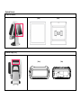
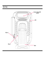
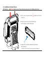
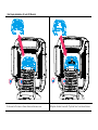
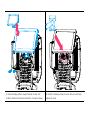
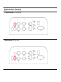
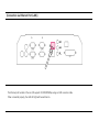
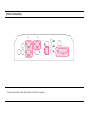
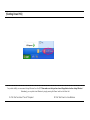
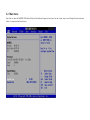
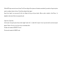
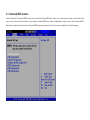
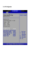
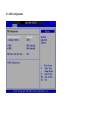
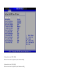
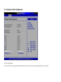
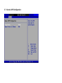
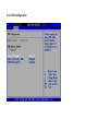
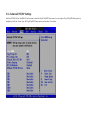
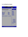
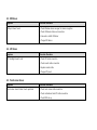
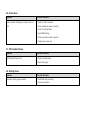
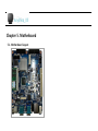
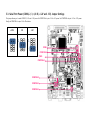
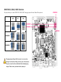
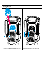
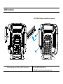
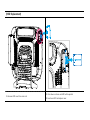
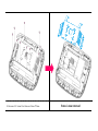
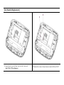
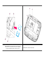
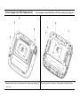
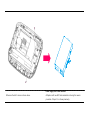
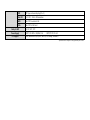
1-5. Installation Recommendations
1. Avoid installing during thunderstorms. (Possibility of dangerous exposure to electricity.)
2. Install away from damp spaces or water-leaks.
3. Beware of static occurrence during installation.
4. Use only ground connected and quality certified power cords and cables.
5. Keep out of direct sun-light, extremely high or low temperatures, or high humidity areas.
6. Install product away from areas prone to shocks or vibration.
7. Install product away from sewing machines, welding equipment, electric stoves, audio equipment and other high frequency generating
equipment.
8. Installation and use in close proximity to an air-conditioning unit is not recommended.
9. Do not connect cables underneath carpets or floorboards.
10. Only use power cables supplied by pre-approved and certified venders.
11. Never use power cords from high power source appliances.
e.g. Electronic heaters, Electric stoves, Audio equipment, Air-conditioners, Refrigerators etc.
12. The use of multiple connections in a shared power outlet/socket is not recommended.
Chapter 2. Product Overview
2-1. Inside Your Package
1. Please check your package and confirm its contents.
2. The POS terminal main unit, power cable, user manual and driver CD are included in the package. If any items are missing or damaged,
please contact your dealer for assistance.
.
[Package Contents]
Driver CD
User manual
AnyShop_D5 main unit
Power cable
[Optional Devices]
[12 inch LCD Monitor]
[Front]
[Rear]
[Customer Display (CDP)]
[Front]
[Rear]
2-2. Pre-installation Preparation
1. Remove protective film from touch-screen to prevent possible operating difficulties.
2. Attach all optional parts before setting up the main POS unit.
2-3. Product Outline
- Each part of product may differ depending on the specific POS model.
[Front View]
LCD & Touchpanel display
Smart Card Reader (SCR)
Magnetic Stripe Reader
(MSR)
Power LED
Power switch
HDD LED
LAN LED
Dual speakers
[Rear View]
Customer display (CDP)
- optional
HDD
USB port
I/O port
Stand
[Power & I/O Ports]
2
1
3
Description
6
4
5
Description
1
Power connector
6
Ethernet port (LAN)
2
PS/2 mouse connector
7
USB port
3
PS/2 keyboard connector
8
Cash box port
4
COM1, COM2, COM3 port
9
LPT port
5
VGA/monitor port
7
8
9
2-4. Installation of Optional Devices
[CDP Installation]
Warning: Completely remove AC power cable when opening main unit or installing optional devices.
1. Insert (-) driver in the grooves marked:
and detach cover from rear
of main unit.
2. Connect to the main unit using the CDP-cable and
insert the display in customer display space.
3. Testing: CDP is successfully installed when system boots
after powering on.
(CDP and 12 inch LCD monitor are used only with the COM4 port.)
[2nd Display Installation: 12 inch LCD Monitor]
1. Remove both screws as shown above and remove cover.
2. Replace standard cover with “Optional Cover” and reinsert screws.
3. Use 2nd display cable to connect monitor to main unit.
5. Use the 2 remaining screws to secure the unit, and finally
4. Place monitor into frame and insert the 4 screws as shown.
replace the cover.
6. Testing: CDP is successfully installed when system boots
after powering on.
(CDP and 12 inch LCD Monitor are used only with COM4 port.)
Warning: Completely remove AC power cable when
opening main unit or installing optional devices.
2nd display installation complete
[Keyboard & Mouse Connection]
1. Keyboard connection: PS/2 type keyboard.
2. Mouse connection: PS/2 type mouse.
[Connection via USB Port]
Four USB ports are provided in the POS unit, two at the rear I/O and two at the side, all of which support the standard USB 2.0.
Some USB devices (optional devices) are only functional with specific driver software installed.
If multiple USB devices are used together, this may result in abnormal functionality.
Using a USB hub with external adapter for supplying power is recommended.
Dependent on the type of device, it is possible for the USB device to be recognized later than normal.
[Connection via Ethernet Port (LAN)]
The Ethernet port located at the rear I/O supports 10/100/1000Mbps using an RJ45 connector cable.
When connected properly, the LAN LED light will be switched on.
[Connection via Line-in Port]
1. Speaker connection
2. Microphone connection
[Printer Connection]
Connect printer cable to either Serial, Parallel or USB port as required.
[Power Cable Connection]
Insert power cable into power connector socket.
INPUT: 100-240V~,50/60Hz 1.5A
OUTPUT: DC 12V 5A
2-5. Basic Operations
[Switching On POS]
» NB: Switch on all peripheral units prior to powering on POS main unit.
1. Press POWER button on the POS unit. (POWER LED will light up.)
2. Confirm that Windows loads correctly.
[Shutting Down POS]
For product stability, we recommend closing Windows from the O/S. Please make sure that you have closed all applications before closing Windows. *
Alternatively, you may shut down Windows by simply pressing the „Power‟ switch on the Main Unit.
1. Click „Start‟ and select „Turn off Computer‟
2. Click „Shut Down‟ to close Windows.
2-6. System Drivers
OPOS driver
We provide UNIPOS drivers for our OPOS driver system for products based on Windows XP.
Supported devices: Cash drawer, CDP (Customer Display Panel), MSR (Magnetic Swipe Reader) and printer.
OPOS driver installation
● Installation method:
Driver will automatically install by clicking SETUP.EXE in your driver CD.
If you require any help with installing or using our OPOS system, please contact our customer service center.
● Folder of contents of POS terminal installation driver:
1. CHIP SET DRV installation
2. VIDEO (VGA) DRV installation
3. TOUCH DRV installation
4. AUDIO DRV installation method
5. LAN DRV installations
6. User Manual
Chapter 3. BIOS Setup Utility
3-1. BIOS Setup Program
The motherboard supports a programmable firmware chip that can be updated using the utility described in the following section. Use the BIOS Setup
program when you are installing a new motherboard, reconfiguring your system, or prompted to “Run Setup”.
Even if you are not prompted to use the Setup program, you can still change the configuration of your computer in the future. For example, you can enable
the security password feature or change the power management settings. This requires you to reconfigure your system using the BIOS Setup program so that
the computer can recognize these changes and record them in the CMOS RAM of the firmware hub.
The firmware hub on the motherboard stores the Setup utility. When you start up the computer, the system provides you with the opportunity to run this
program. Press <Del> during the Power-On-Self-Test (POST) to enter the Setup utility; otherwise, POST continues with its test routines.
If you wish to enter Setup after POST, restart the system by pressing <Ctrl+Alt+Delete>, or by pressing the reset button on the system chassis. You can also
restart by turning the system off and then back on. Only do this as a last option if the first two fail.
The Setup program is designed to make it as easy to use as possible. Being a menu-driven program, it lets you scroll through the various sub-menus and
make your selections from the available options using the navigation keys.
■ The default BIOS settings for this motherboard apply for most conditions to ensure optimal performance. If the system becomes unstable after changing
any BIOS settings, load the default settings to ensure system compatibility and stability. Select the “Load Default Settings” item under the Exit Menu.
■ The BIOS setup screens shown in this section are for reference purposes only, and may not exactly match what you see on your screen.
Legend Box
The keys in the legend bar allow you to navigate through the various setup menus.
Key(s)
Function Description
F1
General help, only for Status Page Setup Menu and Option Page Setup Menu
Esc
Return to the main menu from a sub-menu or prompts you to quit the setup program
←, →
Move to the item in the left or right hand
↑, ↓
Move to previous or next item
Enter
Brings up a selection menu for the highlighted field
+ or PgUp
Moves the cursor to the first field
- or PgDn
Moves the cursor to the last field
F5
Loads the previous values
F6, F7
Loads the fail-safe / optimized defaults
F10
Saves changes and exits Setup
3-2. Main menu
Press <Del> to enter the AMI BIOS CMOS Setup Utility, the Main Menu will appear on the screen. Use the <Arrow> keys to scroll through the items and press
<Enter> to accept or enter the sub-menu.
The Main BIOS setup screen has two main frames. The left frame displays all the options and information associated with your selection. Grayed-out options
cannot be configured; options in blue can. The right frame displays the key legend.
Above the key legend is an area reserved for text to be displayed to help you with your selection. When an option is selected in the left frame, it is
highlighted in white and will often be accompanied by text.
•System time / System date
Use this option to change the system time and date. Highlight “System Time” or “System Date” using the <Arrow> keys and enter the new values using the
keyboard. Press the <Tab> key or the <Arrow> keys to move between fields.
The date must be entered in MM/DD/YYYY format.
The time must be entered in HH:MM:SS format.
3-3. Advanced BIOS Features
Select the “Advanced” tab from the AIMB-2l2 setup screen to enter the “Advanced BIOS Setup” screen. You can select any of the items in the left frame of the
screen, and go to the sub menu for that item. You can display an “Advanced BIOS Setup” option by highlighting it using the <Arrow> keys. All Advanced BIOS
Setup options are described in this section. The Advanced BIOS Setup screen is shown below. The sub menus are described on the following pages.
3-4. CPU Configuration
•Max CPUID Value Limit
This item allows you to limit the CPUID maximum value.
•Execute-Disable Bit Capability
This item allows you to enable or disable the No-Execution page protection technology.
•Hyper Threading Technology
This item allows you to enable or disable Intel Hyper Threading technology.
•Intel® SpeedStepTM tech
When set to disabled, the CPU runs at its default speed. When set to enabled, the CPU speed is controlled by the operating system.
•Intel® C-STATE tech
This item allows the CPU to save power in idle mode.
•Enhanced C-States
CPU idle set to enhanced C-States, disabled by Intel®. C-STATE tech item.
3-5. IDE Configuration
•ATA/IDE Configuration
Configuration options: “Disabled”, “Compatible” or “Enhanced”.
•Configure SATA as
Configuration options: “IDE” or “AHCI”.
•SATAI/SATA2
When entering setup, the BIOS automatically detects the presence of any SATA devices. This displays the status of SATA device auto-detection.
•IDE Detect Time Out (Sec)
This item allows you to select the time-out value for detecting ATA/ATAPI devices.
•AHCI Configuration
AHCI is a new interface specification that allows the SATA controller driver to support advanced features. When entering setup, BIOS automatically detects the
presence of AHCI devices. This option displays the status of auto detection of AHCI devices.
•Onboard Serial port I [3F8 / IRQ4]
This item allows user to adjust serial port l address and IRQ.
•Onboard Serial port 2 [2F8/ IRQ3]
This item allows user to adjust serial port 2 address and IRQ.
•Onboard Serial port 3 [C80/IRQII]
This item allows user to adjust serial port 3 address and IRQ.
•Onboard Serial port 4 [C88/IRQI0]
This item allows user to adjust serial port 4 address and IRQ.
•Onboard Serial port 5 [C90/IRQII]
This item allows user to adjust serial port 5 address and IRQ.
•Onboard Serial port 6 [C98/IRQI0]
This item allows user to adjust serial port 6 address and IRQ
3-6. Hardware Health Configuration
•CPU warning temperature
Use this to set the CPU warning temperature threshold. When the system CPU reaches the warning temperature, the buzzer will beep.
3-7. General ACPI Configuration
•Suspend mode
Select the ACPI state used to suspend system.
•Report Video on S3 Resume
This item allows you to invoke VA BIOS POST on S3/STR resume.
3-8. Advanced ACPI Configuration
•ACPI Version Features
This item allows you to enable RSDP pointers to 64-bit fixed system description tables.
•ACPI APIC support
Include APIC table pointer to RSDT pointer list.
•AMI OEMB table
Include OEMB table pointer to R(x)SDT pointer lists.
•Headless mode
Enable/Disable Headless operation mode through ACPI.
3-9. APM Configuration
•Power Management/APM
Enable/Disable APM power management function.
•Restore on AC Power Loss
This option allows user to set system action on AC power restore after AC power loss. Available options include Power Off, Power On, Last Status.
•Resume On Ring
Disable/Enable RI wake event.
•Resume On RTC Alarm
Disable/Enable RTC wake event.
3-10. USB Configuration
•Legacy USB Support
Enables support for legacy USB. Auto option disables legacy support if no USB devices are connected.
•USB 2.0 Controller Mode
This item allows you to select “HiSpeed” (48O Mbps) or “FullSpeed” (12 Mbps).
•BIOS EHCI Hand-Off
This is a workaround for OSs without EHCI hand-off support. The EHCI ownership change should be claimed by EHCI driver.
3-11. Advanced PCI/PnP Settings
Select the PCI/PnP tab from the AIMB-212 setup screen to enter the Plug & Play BIOS Setup screen. You can display a Plug & Play BIOS Setup option by
highlighting it with the <Arrow> keys. All Plug & Play BIOS Setup options are described in this section.
•Clear NVRAM
Set this value to force the BIOS to clear the Non-Volatile Random Access Memory (NVRAM). The Optimal and Fail-Safe default setting is “No”.
•Plug & Play O/S
When set to “No”, BIOS configures all the devices in the system. When set to “Yes”, the operating system configures the Plug & Play devices not required for
booting.
•PCI Latency Timer
Value in units of PCI clocks for PCI device latency timer register.
•Allocate IRQ to PCI VGA
When set to “Yes”, the system will assign IRQ to PCI VGA card if card requests IRQ. When set to “No”, the system will not assign IRQ to PCI VGA card even if
card requests an IRQ.
•Palette Snooping
This item is designed to solve problems caused by some non-standard VGA card.
•PCI IDE BusMaster
When set to “enabled”, BIOS uses PCI busmastering for reading/writing to IDE drives.
•OffBoard PCI/ISA IDE Card
Some PCI IDE cards may require this to be set to the PCI slot number that is holding the card. Setting to “Auto” works for most PCI IDE cards.
•IRQ 3 / 4 / 5 / 7 / 9 / 10 /11
This item allows you assign interrupt types for IRQ-3, 4, 5, 7, 9, 10, 11.
•DMA Channel 0 / 1 / 3 / 5 / 6 / 7
When set to “Available”, will specify DMA is available to be used by PCI/PnP devices. When set to “Reserved”, will specify DMA is reserved for use by legacy
ISA devices.
•Reserved Memory Size
This item allows you to reserve a set amount of memory for legacy ISA devices.
3-12. Boot Settings Configuration
•Quick Boot
This item allows BIOS to skip certain tests while booting. This will decrease the time needed to boot the system.
•Quiet Boot
If this option is set to “Disabled”, the BIOS displays normal Power On Self Test (POST) messages. If “Enabled”, an OEM Logo is shown instead of POST
messages.
•Bootup Num-Lock
Select the Power-on state for Num-Lock.
•Wait For „F1‟ If Error
Wait for the F1 key to be pressed if an error occurs.
3-13. Security Setup
Select “Security Setup” from the PCM-9562 Setup main BIOS setup menu.
•Change Supervisor / User Password
Allows you to either set a new password, or change an old password.
3-14. Advanced Chipset Settings
3-14-1. North Bridge Chipset Configuration
•DRAM Frequency
This item allows you to manually change DRAM frequency.
•Configure DRAM Timing by SPD
This item allows you to enable or disable detection by DRAM SPD.
•Initiate Graphic Adapter
This item allows you to select which graphics controller to use as the primary boot device.
•Internal Graphics Mode Select
Select the amount of system memory used by the internal graphics device.
3-14-1-1. Video Function Configuration
•DVMT Mode Select
Displays the active system memory mode.
•DVMT/FIXED Memory
Specifies the amount of DVMT/FIXED system memory to be allocated as video memory.
•Boot Display Device
Select boot display device at post stage.
•Flat Panel Type
This item allows you to select which panel resolution you want.
3-14-2. South Bridge Chipset Configuration
•USB Functions
Configurable options: Disabled, 2 USB Ports, 4 USB Ports, 6 USB Ports or 8 USB Ports.
•USB 2.0 Controller
Enables or disables the USB 2.O controller.
•LANI controller
Enables or disables the GbE controller.
•SLP_S4# Min. Assertion Width
This item allows you to set a delay of a set number of seconds.
3-15. Exit Options
•Save Changes and Exit
When you have completed system configuration, select this option to save your changes, exit BIOS setup and reboot the computer so the new system
configuration parameters can take effect.
1. Select “Save Changes and Exit” from the “Exit” menu and press <Enter>. The following message appears:
Save Configuration Changes and Exit Now? [Ok] [Cancel]
2. Select “Ok” or “Cancel”.
•Discard Changes and Exit
Select this option to quit Setup without making any permanent changes to the system configuration.
1. Select “Discard Changes and Exit” from the “Exit” menu and press <Enter>. The following message appears:
Discard Changes and Exit Setup Now? [Ok] [Cancel]
2. Select “Ok” to discard changes and exit.
•Discard Changes
1. Select “Discard Changes” from the Exit menu and press <Enter>.
•Load Optimal Defaults
The AIMB-212 automatically configures all setup items to optimal settings when you select this option. “Optimal Defaults” are designed for maximum system
performance, but may not work best for all computer applications. In particular, do not use the “Optimal Defaults” if your computer is experiencing system
configuration problems.
1. Select “Load Optimal Defaults” from the “Exit” menu and press <Enter>.
Chapter 4. Troubleshooting
4-1. Network Issues
Symptom
Corrective Procedure
Cannot access LAN
▪ Check if hub or switch is working correctly
▪ Check RJ45 cable connection
▪ Check if LAN LEDs are on/off
▪ Reinstall LAN card
▪ Replace motherboard
4-2. MSR Issues
Symptom
Corrective Procedure
MSR does not respond
▪ Check MSR reader cable connection
▪ Check motherboard and LCD cable connection
▪ Check MSR board cable connection
4-3. USB Issues
Symptom
Corrective Procedure
USB port doesn‟t work
▪ Check Windows device manager for device recognition
▪ Check USB device status and connection
▪ Erase and re-install USB driver
▪ Change USB device
4-4. LCD Issues
Symptom
Corrective Procedure
LCD backlight doesn‟t work
▪ Check LCD cable connection
▪ Check inverter cable connection
▪ Replace inverter cable
▪ Change LCD panel
4-5. Touch-screen Issues
Symptom
Corrective Procedure
Touch-screen doesn‟t detect touch operations
▪ Check touch-screen cable connection
▪ Check motherboard and LCD cable connection
▪ Check BIOS set-up
4-6. Power Issues
Symptom
Corrective Procedure
System switches off abruptly and system does not
▪ Check A/C cable connection
load
▪ Check motherboard power connection
▪ Check CPU settings/status
▪ Check DRAM settings
▪ Check power button cable connection
▪ Change power supply unit
4-7. PS/2 Keyboard Issues
Symptom
Corrective Procedure
PS/2 Keyboard doesn‟t work
▪ Check card-reader cable
▪ Check CN6 jumper
4-8. Booting Issues
Symptom
Corrective Procedure
Re-booting during system operation
▪ Check SATA cable connection
▪ Check memory status
4-9. Printer Issues
Symptom
Corrective Procedure
Printer won‟t operate
▪ Check printer power supply
▪ Replace printer paper roll
▪ Check printer cable
Chapter 5. Motherboard
5-1. Motherboard Layout
5-2. Clearing CMOS
This jumper allows you to clear the Real Time Clock (RTC) RAM in CMOS. You can clear the CMOS memory of date, time, and system setup parameters by
erasing the CMOS RTC RAM data. The onboard button cell battery powers the RAM data in CMOS, which include system setup information such as system
passwords.
To erase the RTC RAM:
1. Turn OFF the computer and unplug the power cord.
2. Remove the onboard battery.
3. Move the jumper cap from pins 1-2 (default) to pins 2-3. Keep the cap on pins 2-3 for 5~10 seconds, then move the cap back to pins 1-2.
4. Re-install the battery.
5. Plug in the power cord again and turn ON the computer.
6. Hold down the <Del> key during the boot process and enter BIOS setup to re-enter data.
Except when clearing the RTC RAM, never remove the cap on CLRTC jumper default position. Removing the cap will cause system boot failure.
Normal (Default)
Clear CMOS
5-3. Serial Port Power (COM1, 2, 3, 4, 6 RI, +12V and +5V) Jumper Settings
This jumper allows you to select COM1 RI, +5V and +12V power. Set COMP1SELx to pins 5-6 for +5V power. Set COMP1SELx to pins 1-2 for +12V power.
Finally, set COMP1SELx to pins 3-4 for RI selection.
+12V
RI
+5V
COM6
COMP1SEL6
COM4
COMP1SEL4
COMP1SEL2
COMP1SEL1
COMP1SEL1
COM5 RS232, RS422, RS485 Selection
This jumper allows you to select COM5 RS232, RS422, RS485. Changing jumpers will select different RSxxx protocols.
+12V
RI
JCOMPWR3
+5V
JCOMPWR2
JCOMPWR1
JCOMPWR1
COMP1SEL5
JCOMPWR2
JCOMPWR3
Changing jumper settings while the power is on can severely
damage the motherboard. Always turn the power off and remove
the power source from the motherboard before attempting any
changes. Please contact your dealer before replacing it.
Chapter 6. Maintenance
6-1. Safety Warning
POSBANK will not be held responsible for repairs conducted via service providers other than those officially specified by the seller.
General Guidelines
1. Always disconnect the unit from the power outlet.
2. Disconnect all cables from the POS main unit before attempting reparation.
3. Keep all components in the static-proof packaging provided until ready for installation.
4. If the device still is not functioning after repair, please turn off the POS unit and contact the customer service center for a follow-up inspection.
5. We recommend that power supply unit (PSU) checks and monitor repairs only be performed at a certified service center.
[Detaching Main Unit]
1. Remove the 2 screws as shown above and take off cover.
2. Remove the 8 screws from the frame under the cover.
3. Detach main unit from stand.
4. Main unit is now detached.
[MSR Installation]
» PS2, USB and Serial port connections are supported
1. Remove dummy cover at the rear left of the main unit.
2. Connect MSR cable to MSR unit.
3. Affix MSR to main unit using 2 screws as shown.
[HDD Replacement]
1. Remove HDD cover from main unit.
2. Press down as shown and HDD will be ejected.
3. Insert new HDD and replace cover.
[Motherboard Replacement]
»
We recommend removing MSR, HDD and CDP before replacing the motherboard.
1. Remove the 8 screws on reverse side of main unit using a (+) driver
and take off the rear cover.
Rear cover is now removed
2. Remove all 10 screws from frame and take off frame.
Frame is now removed
FAN
DUCT
3. When frame is removed, FAN and DUCT need to be separated.
4. Remove the screws as shown above and pull out FAN and DUCT.
6. Remove cable from motherboard. Motherboard is now removed.
5. Next, remove the last 4 screws as shown above.
7. Replace with new motherboard and reassemble unit using the
reverse procedure of steps 1-6 as shown previously.
[Fan/Heatsink Replacement]
1. Separate rear cover and frame from rear side of main unit.
(See P.78 & P.79 for reference.)
2. Remove the screws as shown above and pull out FAN and DUCT.
FAN
DUCT
FAN and DUCT are removed and can now be replaced.
(To replace the Heatsink, please continue to part 3.)
3. Remove the 4 screws as shown above.
HEATSINK
5. Remove the 2 screws as shown above and eject heatsink.
4. Disconnect cable from motherboard.
6. Remove cable from heatsink. HEATSINK is now removed.
7. Reassemble unit using the reverse procedure of steps 1-6.
[Power Supply Unit (PSU) Replacement]
» We recommend removing MSR, HDD and CDP before replacing power supply unit.
1. Remove the 8 screws from the reverse of the main unit and take off
rear cover.
2. Next, remove the 10 screws as shown above and take off frame.
Power supply unit is now removed.
3. Remove the last 2 screws as shown above.
4. Replace with new HDD and reassemble unit using the reverse
procedure of steps 1-3 as shown previously.
[Memory (RAM) Replacement]
Please refer to “5-1. Motherboard Layout” for RAM location.
1. Push fixtures on both sides outwards (as shown above).
2. Remove the memory from its slot.
3. Insert new memory into slot and press lightly to fix into place.
6-2. Technical Specifications (AnyShop D5)
CPU
Intel Pineview-D D510
Chipset
ICH8M
HDD
SATA 2.5inch (Default 160GB)
Memory
DDR2 SODIMM x 1 slot (Default 1GB up to 2GB)
VGA
Intel Gen3.5+GFX Render Core
Display
15” TFT LCD with 5-wired resistive Touch Screen 1024 x 768 resolution
Internal I/O
External I/O
Optional
USB
3 Ports (reserved for Touch controller, SCR EMV card, Camera, MSR controller)
PS/2
1 Keyboard with pin header
RS-232
COM 4 reserved for VFD COM 5 & 6 with 9pin header
D-SUB
Reserved for 2nd display
Extension
Mini PCIe
LVDS
Main display use
Parallel
1 port
USB
Rear 2, Side 2
PS/2
Mouse 1 / Keyboard 1
RS-232
COM 1 ~ 3 with + 5/12V power output on 9pin
LAN
GbE LAN
Audio
Each 1 Line-out / Line-in / Mic.
MSR
Comply with ISO 7811, Support 1 & 2 & 3 track
SCR
EMV level
Dallas
Dallas I-button reader
VFD
VFD type customer display (20 x 2)
2nd LCD
12.1" LCD : 1024 x 768 resolution
WiFi
Mini PCI for wireless LAN
VGA
Mini PCI for VGA card
Safety & EMI
CE, FCC, KCC, CCC
Power Supply
INPUT: 100-240V~,50/60Hz 1.5A
OS Support
OUTPUT: DC 12V 5A
Linux, Windows 2000/XP/XPE, WEPOS, POS Ready, Windows 7
* Specifications are subject to change without prior notice