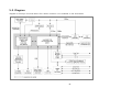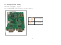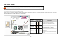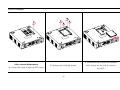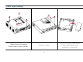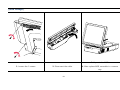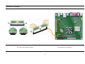
1
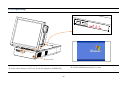
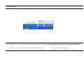
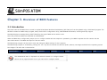
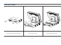
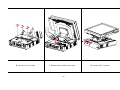
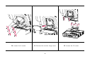
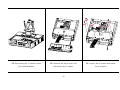
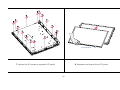
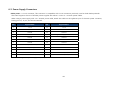
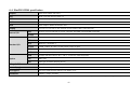
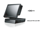
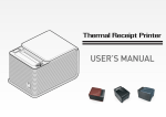
INDEX Chapter 1. Caution Chapter 5. Motherboard jumper setting Chapter 3. BIOS SETUP UTILITY 1-1. Warranty ………………………………………………. 3 1-2. Copyright ……………………………….…………….. 4 3-2. BIOS Flash Memory Organization …………... 26 5-2. Diagram ………………………………………………………………. 41 1-3. Notice for safety ………….………………………… 4 3-3. Resource Configuration …………………………… 27 5-3. Serial port ……………………………………………………………. 42 1-4. Circumstance limitation …………….………… 5 3-4. Resource Configuration …………………………… 27 5-4. Jumper setting…………………………………………..……………. 43 1-5. Installation tips …………………………………….. 7 3-5. Legacy USB Support ………………………………... 28 3-6. BIOS Updates …………………………………………... 28 3-7. BIOS Recovery …………………………………………. 30 6-1. Safety & danger precaution ……………………………..... 44 Chapter 2. Product overview 3-1. Introduction …………………………………………….. 25 5-1. Motherboard Layout …………………………………………… 38 Chapter 6. Replacement 2-1. Checking package ……………………………….. 8 3-8. Boot Options …………………………………………… 30 - Rear cover change …………………………………………………. 45 2-2. Preparing before installation …………….…. 11 3-9. Adjusting Boot Speed ……………………………... 32 - Motherboard change ………..……………………………………. 46 2-3. Product consist ……………….…………………… 11 3-10. BIOS Security Features ………………………….. 33 - HDD change …………………………………………………………… 52 2-4. Setup Optional Item ………………………………. - Power supply change 15 ……………………………………………... Chapter 4. Trouble-shooting - CDP installation …………….……………….…………. 15 - Installation of Keyboard & mouse …..………. 16 4-1. Network trouble ………………………………………. - Installation of USB device ………………………... 17 4-2. MSR trouble - Ethernet port connection …………………………. 53 - MSR change …………………………………………………………… 54 34 - MEMORY change …..………………………………………………. 55 ……………………….……………………. 34 - HEATSINK change ……………..…………………………..………. 56 18 4-3. USB trouble …….……………………………………….. 35 - monitor change ………………………………………………….….. 57 - Speaker and MIC. connection ………………….. 19 4-4. LCD trouble ……………..………………………………. 35 - Monitor AD board, Control board, Hub board, - Printer connection ……………………………….……. 20 4-5. Touch screen trouble ………………………………. 35 Touch controller, Inverter, LCD Panel change …………… - Power cable connection ………..………………..... 21 4-6. Power trouble ……………………………………..….. 36 - POS operating …………………………...……………… 22 4-7. PS/2 Keyboard trouble ………………………….... 36 6-2. Power Supply Connectors 64 - POS closing ………………………………………………. 23 4-8. Boot trouble …………………………………………….. 36 6-3. Reference to upgrade and power supply …………...... 66 - System driver ……………….…………………………… 24 4-9. Printer trouble …………………………………………. 37 6-4. SlimPOS ATOM specification ………………………………. 67 -2- 60 Chapter 1. Caution 1-1. Warranty We guarantee our POS terminal product and its parts against defects in materials and workmanship under proper use for a standard period of 2 years from the date of original purchase. During this period, we will repair or replace a defected and/or faulty product or parts without charge for spare and labor to the purchaser. The 1st year is applied with free workmanship and new or refurbished replacement parts with one-way freight cost born by the seller and the customer shall be responsible for return delivery charge. The 2nd year is applied also non chargeable for workmanship and parts, but limited warranty with round-way freight cost born by the customer. Products out of the warranty period or scope shall be diagnosed at customer's expense. We will charge for repair and delivery in case of customer's handling mistake, carelessness and natural disasters. -3- 1-2. Copyright This publication including all photograph, illustration and software, is protected under international copyright law with all rights reserved in manufacturer. Neither this manual, nor any of the material contained herein, may be reproduced without written consent of the author. 1-3. Notice for safety 1. We recommend using proper power voltage against fire and electric shock. 2. Avoid exposing the product to direct sunlight and do not use the product near area of high moistures. - It might cause low reliability and operating disorder. 3. Be aware of electro-static on PCB of system with anti-static appliance. - It is possible to be reason for low reliability and short life term. 4. Place a product away from static occurred area. - It is a matter to be low performance and reduce life cycle. 5. Do not disturb metal material or obstacle in product. - It is dangerous about fire and electric shock. 6. Use product in simple power cord plug-in circumstance. - It is occurred to fire, electric shock and system disorder on electricity. 7. Be careful of other electronics having possibility with high frequency, electronic and magnetic affect (Ex. Audio, Electronic-range, etc) - There is a strong possibility to make a product out-of-order or system error. -4- 1-4. Circumstance limitation ● Installation and maintenance service We recommend you to have service about product installation, maintenance and repair service from nominated service center and agent office. It is not our responsibility about out of order or system error after service and/or checking system from non predicted service provider. ● Notice against high frequency This product is qualified by FCC, CE, EMI and MIC compliance, thus it is governed with the previous qualification regulation to the safety. However, it is affected by the other high frequency generated. We don't consider system error and disorder due to the above affection. ● Notice about noise We request to use our product away from heater, motor, fluorescent light, TV and similar which makes noise sounds. Electric noise makes interruption and interference against normal operating. ● Request of installation circumstance The most suitable environment is within 65% humidity in 10 ~ 30℃ temperature. Please also install and use out of direct sun-light. -5- ● Cleansing It is caused of damage on appearance and exterior surface after cleaning with chemical cleanser. We recommend you to use soft cloth, especially LCD screen. ● Product liability 1. We prohibit product to use for other purpose, but not POS. It is not supported of usual PC operating & interface support. 2. This is for professional business field only to shop, not home appliance. 3. This is consisted with hardware and software politically. 4. It is guaranteed normal operating on stable power supply. -6- 1-5. Installation tips 1. Avoid installing in lightning and thunderstorm day. (Dangerous to expose electricity) 2. Be away from damp space and water-leaked place for installation. 3. Be aware of static occurrence during installation. 4. Allow using only ground connected and quality certificated power code and cable. 5. Keep out of direct sun-light, extreme high or low temperature, and humid area. 6. Take away from impact, shocked, and tremble place. 7. Place product to avoid with sewing machine, Welding instrument, electronic wave range, Audio and other high frequency generated equipment. 8. Do not recommend to use next by air conditioner. 9. Prohibit connecting cables under carpet and floor. 11. Use another power code from high power source appliances. (Ex. Electronic heater, Electronic wave range, Audio, Air-conditioner, Refrigerator, etc) 12. Do not recommend to use multiple connections in same power outlet/socket. -7- Chapter 2. Product overview 2-1. Checking package 1. Confirm packing detail which is listed on user manual in package. 2. We provide POS terminal main unit, power cord, user manual and driver CD basically. » It is possible to download user manual and driver CD from our web. -8- [Package contents] Driver CD User manual Power code SlimPOS main unit -9- [Options : Customer display] -10- 2-2. Preparing before installation 1. Remove masking tape for Touch screen protection. (It may cause abnormal operating when masking tape is not removed.) 2. Install option product(customer display) first when it need to set up with POS main unit. 2-3. Product consist - Detail indication can be different with each POS terminal model. - It is provided with proper data sheet per model from our web. -11- [Front view] SMART CARD READER LCD & TOUCH PANNEL DISPLAY MAGNETIC READER USB Port POWER, HDD, LAN LED POWER SWITCH -12- STRIPE [Rear view] Display Hinge Real For Cable Management Customer Display Cover Real Connectors -13- [Power & I/O View] 1 2 5 7 4 4 4 3 6 Description Description 1 AC power in 5 Parallel port 2 PS/2 mouse port 6 USB port 3 PS/2 7 LAN port 4 COM1, COM2, COM3 port keyboard port -14- 2-4. Setup Optional Item [CDP installation] Notice : Remove AC power cord completely in installation or dissection of CDP. 1. 본체 뒷면의 옵션 커버 분리합니다. 2. 본체 커버에 PCB를 장착한 뒤, 케이블을 연결합니다. 3. 그림과 같이 4개의 나사를 연결하여 CDP를 본체에 장착합니다. -15- 완성. 본체 전원을 끄고 다시 켠 후 CDP 에 초기 화면이 정상적으로 나타나면 연결에 성공한 것입니다. [Installation of Keyboard and mouse] 1. Keyboard installation : Connection of PS/2 type keyboard. 2. Mouse installation : Connection of PS/2 type mouse. -16- [Installation of USB device] USB port is provided 3 ports in rear I/O and 2 ports in side I/O supported standard USB 2.0. Some USB device(optional device) is operated only with specific driver software installed. It may cause abnormal working if it is connected with multiple USB devices together. We recommend you to use USB hub for supplying power with external adapter. It is possible to recognize USB device lately as following device type. -17- [Ethernet port connection : LAN cable] LAN LED Ethernet port support 10/100/1000Mbps located with rear I/O. Connector type is RJ45. 정상적으로 연결된 경우 RJ45 커넥터 상단 LAN LED 에 불이 들어옵니다. -18- [Speaker and MIC. connection] 1. Speaker connection 2. MIC. connection -19- [Printer connection] Connect printer cable among Serial, Parallel and USB port you required. -20- [Power cable connection] Connect power cable to power connector. This POS terminal support 110V ~ 220V » We recommend you to use grounded power connection in AC adaptor connection with power code. -21- [POS operating] Power button » Power on POS accessory and peripherals first before POS power-on. 1. Press power button in POS unit. (It will be lighted on POWER LED.) -22- 2. Confirm Windows booting if it is fine. [POS closing] We recommend you to close Windows in O/S for product stability. Please close all application programs before Windows termination. 1. Select ‘Turn off Computer’ on Start in Windows initial screen 2. Click ‘Turn off’ in close windows -23- 2-5. System driver OPOS driver We provide UNIPOS driver for OPOS driver system to our product based on Windows XP O/S. You can download also from our web if you need latest version of OPOS driver. Supported device : Cash drawer, CDP(Customer display), MSR(Magnetic Card Reader) and Printer OPOS driver installation ● Installation method Component is registered automatically with clicking SETUP.EXE in driver CD. We recommend you to have guide service to use our OPOS system from our customer service center. ● Folder contents of POS terminal installation driver 1. CHIP SET DRV installation 2. VIDEO (VGA) DRV installation 3. TOUCH DRV installation 4. AUDIO DRV installation method 5. LAN DRV installations 6. User’s Manual\ ! -24- Chapter 3. Overview of BIOS Features 3-1. Introduction The board uses an Intel BIOS that is stored in the Serial Peripheral Interface Flash Memory (SPI Flash) and can be updated using a disk-based program. The SPI Flash contains the BIOS Setup program, POST, the PCI auto-configuration utility, LAN EEPROM information, and Plug and Play support. The BIOS displays a message during POST identifying the type of BIOS and a revision code. The initial production BIOSs are identified as LF94510J.86A. When the BIOS Setup configuration jumper is set to configure mode and the computer is powered-up, the BIOS compares the CPU version and the microcode version in the BIOS and reports if the two match. The BIOS Setup program can be used to view and change the BIOS settings for the computer. The BIOS Setup program is accessed by pressing the <F2> key after the Power-On Self-Test (POST) memory test begins and before the operating system boot begins. The menu bar is shown below. Maintenance Main Advanced Security The maintenance menu is displayed only when the board is in configure mode. Section 2.3 on page 49 shows how to put the board in configure mode. -25- Power Boot Exit BIOS Setup Program Menu Bar Maintenance Main Advanced Security Power Boot Exit Clears Displays Configures Sets Configures passwords and processor advanced passwords power displays and memory features and security management changes to available features features and Setup power supply program processor configuration information through the chipset controls Table 27 lists the function keys available for menu screens. Table 27. BIOS Setup Program Function Keys Key(s) Description ←, → Selects a different menu screen (Moves the cursor left or right) ↑, ↓ Selects an item (Moves the cursor up or down) Tab Selects a field (Not implemented) Enter Executes command or selects the submenu F9 Load the default configuration values for the current menu F10 Save the current values and exits the BIOS Setup program Esc Exits the menu 3-2. BIOS Flash Memory Organization The Serial Peripheral Interface Flash Memory (SPI Flash) includes an 4 Mbit (512 KB) flash memory device. -26- Selects boot Saves or options discards options 3-3. Resource Configuration 3-3-1. PCI* Autoconfiguration The BIOS can automatically configure PCI devices. PCI devices may be onboard or add-in cards. Autoconfiguration lets a user insert or remove PCI cards without having to configure the system. When a user turns on the system after adding a PCI card, the BIOS automatically configures interrupts, the I/O space, and other system resources. Any interrupts set to Available in Setup are considered to be available for use by the add-in card. 3-4. System Management BIOS (SMBIOS) SMBIOS is a Desktop Management Interface (DMI) compliant method for managing computers in a managed network. The main component of SMBIOS is the Management Information Format (MIF) database, which contains information about the computing system and its components. Using SMBIOS, a system administrator can obtain the system types, capabilities, operational status, and installation dates for system components. The MIF database defines the data and provides the method for accessing this information. The BIOS enables applications such as third-party management software to use SMBIOS. The BIOS stores and reports the following SMBIOS information: • BIOS data, such as the BIOS revision level • Fixed-system data, such as peripherals, serial numbers, and asset tags • Resource data, such as memory size, cache size, and processor speed • Dynamic data, such as event detection and error logging Non-Plug and Play operating systems require an additional interface for obtaining the SMBIOS information. The BIOS supports an SMBIOS table interface for such operating systems. Using this support, an SMBIOS service-level application running on a non-Plug and Play operating system can obtain the SMBIOS information. Additional board information can be found in the BIOS under the Additional Information header under the Main BIOS page. -27- 3-5. Legacy USB Support Legacy USB support enables USB devices to be used even when the operating system’s USB drivers are not yet available. Legacy USB support is used to access the BIOS Setup program, and to install an operating system that supports USB. By default, Legacy USB support is set to Enabled. Legacy USB support operates as follows: 1. When you apply power to the computer, legacy support is disabled. 2. POST begins. 3. Legacy USB support is enabled by the BIOS allowing you to use a USB keyboard to enter and configure the BIOS Setup program and the maintenance menu. 4. POST completes. 5. The operating system loads. While the operating system is loading, USB keyboards and mice are recognized and may be used to configure the operating system. (Keyboards and mice are not recognized during this period if Legacy USB support was set to Disabled in the BIOS Setup program.) 6. After the operating system loads the USB drivers, all legacy and non-legacy USB devices are recognized by the operating system, and Legacy USB support from the BIOS is no longer used. 7. Additional USB legacy feature options can be access by using Intel Integrator Toolkit. To install an operating system that supports USB, verify that Legacy USB support in the BIOS Setup program is set to Enabled and follow the operating system’s installation instructions. 3-6. BIOS Updates The BIOS can be updated using either of the following utilities, which are available on the Intel World Wide Web site: • Intel® Express BIOS Update utility, which enables automated updating while in the Windows environment. Using this utility, the BIOS can be updated from a file on a hard disk, a USB drive (a flash drive or a USB hard drive), or a CD-ROM, or from the file location on the Web. • Intel® Flash Memory Update Utility, which requires booting from DOS. Using this utility, the BIOS can be updated from a file on a hard disk, a USB drive -28- (a flash drive or a USB hard drive), or a CD-ROM. Both utilities verify that the updated BIOS matches the target system to prevent accidentally installing an incompatible BIOS. Review the instructions distributed with the upgrade utility before attempting a BIOS update. BIOS update utilities = http://support.intel.com/support/motherboards/desktop/sb/CS-022312.htm. 3-6-1. Language Support The BIOS Setup program and help messages are supported in US English. Additional languages are available in the Integrator’s Toolkit utility. Check the Intel website for details. 3-6-2. Custom Splash Screen During POST, an Intel® splash screen is displayed by default. This splash screen can be augmented with a custom splash screen. The Intel® Integrator’s Toolkit that is available from Intel can be used to create a custom splash screen. If you add a custom splash screen, it will share space with the Intel branded logo. Intel Integrator Toolkit= http://developer.intel.com/design/motherbd/software/itk/ Additional Intel® software tools= http://developer.intel.com/products/motherboard/dg965wh/tools.htm and http://developer.intel.com/design/motherbd/software.htm -29- 3-7. BIOS Recovery It is unlikely that anything will interrupt a BIOS update; however, if an interruption occurs, the BIOS could be damaged. Table 28 lists the drives and media types that can and cannot be used for BIOS recovery. The BIOS recovery media does not need to be made bootable. Table 28. Acceptable Drives/Media Types for BIOS Recovery Media Type Can be used for BIOS recovery? CD-ROM drive connected to the Parallel ATA interface Yes CD-ROM drive connected to the Serial ATA interface Yes USB removable drive (a USB Flash Drive, for example) Yes USB diskette drive (with a 1.44 MB diskette) NO USB hard disk drive NO BIOS recovery= http://support.intel.com/support/motherboards/desktop 3-8. Boot Options In the BIOS Setup program, the user can choose to boot from a diskette drive, hard drive, USB drive, USB flash drive, CD-ROM, or the network. The default setting is for the diskette drive to be the first boot device, the hard drive second, and the ATAPI CD-ROM third. If enabled, the last default boot device is the network. 3-8-1. CD-ROM Boot Booting from CD-ROM is supported in compliance to the El Torito bootable CD-ROM format specification. Under the Boot menu in the BIOS Setup program, ATAPI CDROM is listed as a boot device. Boot devices are defined in priority order. Accordingly, if there is not a bootable CD in the CD-ROM drive, the system will attempt to boot from the next defined drive. -30- 3-8-2. Network Boot The network can be selected as a boot device. This selection allows booting from the onboard LAN or a network add-in card with a remote boot ROM installed. Pressing the <F12> key during POST automatically forces booting from the LAN. To use this key during POST, the User Access Level in the BIOS Setup program's Security menu must be set to Full. 3-8-3. Booting Without Attached Devices For use in embedded applications, the BIOS has been designed so that after passing the POST, the operating system loader is invoked even if the following devices are not present: • Video adapter • Keyboard • Mouse 3-8-4. Changing the Default Boot Device During POST Pressing the <F10> key during POST causes a boot device menu to be displayed. This menu displays the list of available boot devices (as set in the BIOS setup program’s Boot Device Priority Submenu). Boot Device Menu Options Key(s) Description ↑, ↓ Selects a default boot device Enter Exits the menu, saves changes, and boots from the selected device Esc Exits the menu without saving changes -31- 3-9. Adjusting Boot Speed These factors affect system boot speed: • Selecting and configuring peripherals properly • Optimized BIOS boot parameters 3-9-1. Peripheral Selection and Configuration The following techniques help improve system boot speed: • Choose a hard drive with parameters such as “power-up to data ready” less than eight seconds, that minimize hard drive startup delays. • Select a CD-ROM drive with a fast initialization rate. This rate can influence POST execution time. • Eliminate unnecessary add-in adapter features, such as logo displays, screen repaints, or mode changes in POST. These features may add time to the boot process. • Try different monitors. Some monitors initialize and communicate with the BIOS more quickly, which enables the system to boot more quickly. 3-9-2. BIOS Boot Optimizations Use of the following BIOS Setup program settings reduces the POST execution time. • In the Boot Menu, set the hard disk drive as the first boot device. As a result, the POST does not first seek a diskette drive, which saves about one second from the POST execution time. • In the Peripheral Configuration submenu, disable the LAN device if it will not be used. This can reduce up to four seconds of option ROM boot time. It is possible to optimize the boot process to the point where the system boots so quickly that the Intel logo screen (or a custom logo splash screen) will not be seen. Monitors and hard disk drives with minimum initialization times can also contribute to a boot time that might be so fast that necessary logo screens and POST messages cannot be seen. This boot time may be so fast that some drives might be not be initialized at all. If this condition should occur, it is possible to introduce a programmable delay ranging from three to 30 seconds (using the Hard Disk Pre-Delay feature of the Advanced Menu in the Drive Configuration Submenu of the BIOS Setup program). -32- 3-10. BIOS Security Features The BIOS includes security features that restrict access to the BIOS Setup program and who can boot the computer. A supervisor password and a user password can be set for the BIOS Setup program and for booting the computer, with the following restrictions: • The supervisor password gives unrestricted access to view and change all the Setup options in the BIOS Setup program. This is the supervisor mode. • The user password gives restricted access to view and change Setup options in the BIOS Setup program. This is the user mode. • If only the supervisor password is set, pressing the <Enter> key at the password prompt of the BIOS Setup program allows the user restricted access to Setup. • If both the supervisor and user passwords are set, users can enter either the supervisor password or the user password to access Setup. Users have access to Setup respective to which password is entered. • Setting the user password restricts who can boot the computer. The password prompt will be displayed before the computer is booted. If only the supervisor password is set, the computer boots without asking for a password. If both passwords are set, the user can enter either password to boot the computer. • For enhanced security, use different passwords for the supervisor and user passwords. • Valid password characters are A-Z, a-z, and 0-9. Passwords may be up to 16 characters in length. Table 30 shows the effects of setting the supervisor password and user password. This table is for reference only and is not displayed on the screen. Supervisor and User Password Functions (Note: If no password is set, any user can change all Setup options) Password Set Supervisor Mode User Mode Setup Options Password to Enter Setup Password During Boot Neither Can change all Can change all None None None options (Note) options (Note) Supervisor only Can change all options Can change a limited number Supervisor Password Supervisor None User only N/A Can change all options Enter Password User User Supervisor Can change all Can change a limited number Supervisor Password Supervisor or Supervisor or and user set options of options Enter Password user user of options Clear User Password -33- Chapter 4. Trouble-shooting 4-1. Network trouble Symptom Corrective Procedure Cannot access LAN Check if hub or switch is working correctly Check the RJ45 cable connection Check if the RJ-45 LEDs are on Reinstall LAN card Replace motherboard 4-2. MSR trouble Symptom Corrective Procedure MSR does not response ▪ Check MSR reader cable connection ▪ Check motherboard and LCD cable connection ▪ Check MSR board cable connection -34- 4-3. USB trouble Symptom Corrective Procedure USB port doesn’t work at all ▪ Check Windows device manager about device recognition ▪ Check USB device status and connection ▪ Erase and re-install USB driver ▪ Change USB device 4-4. LCD trouble Symptom Corrective Procedure LCD backlight doesn’t work ▪ Confirm LCD cable connection ▪ Check inverter cable connection ▪ Replace inverter cable ▪ Change LCD panel 4-5. Touch screen trouble Symptom Corrective Procedure Touch screen doesn’t detect touch operating ▪ Confirm touch screen cable connection ▪ Check motherboard and LCD cable connection ▪ Check BIOS set-up -35- 4-6. Power trouble Symptom Corrective Procedure Suddenly power off and system is not executed ▪ Check A/C cable connection ▪ Confirm motherboard power connection ▪ Check CPU setting status ▪ Check DRAM setting ▪ Check power button cable connection ▪ Change power supply unit 4-7. PS/2 Keyboard trouble Symptom Corrective Procedure PS/2 Keyboard is not work ▪ Check card reader cable ▪ In non-setting with card reader, check CN6 jumper 4-8. Boot trouble Symptom Corrective Procedure Re-booting during system operating ▪ Check SATA cable connection ▪ Check memory status -36- 4-9. Printer trouble Symptom Corrective Procedure Printer is not operated ▪ Check printer power supply ▪ Replace printer paper roll ▪ Check printer cable -37- Chapter 5. Motherboard jumper setting 5-1. Motherboard Layout -38- Description A : PCI Conventional bus add-in card connector B : Front panel audio header Front panel USB headers C : Back panel connectors D : +12 V power connector (ATX12V) E : GMCH fan header F : Chassis fan header G : Intel Atom processor H : Intel 82945GC GMCH I : DIMM socket J : Main power connector K : Parallel ATA IDE connector L : SATA connectors [2] M : Front panel I/O header N : Battery O : Intel 82801GB I/O Controller Hub (ICH7) P : BIOS Setup configuration jumper block Q : Front panel USB headers S : S/PDIF connector -39- Form Factor Processor Mini-ITX, compatible with microATX (6.75 inches by 6.75 inches [171.45 millimeters by 171.45 millimeters]) Support for the following: • Soldered-down Dual-Core Intel® Atom® processor • One 240-pin DDR2 SDRAM Dual Inline Memory Module (DIMM) socket Memory • Support for DDR2 533 MHz and DDR2 400 MHz DIMMs (DDR2 800 MHz and DDR 667 MHz validated to run at 533 MHz only) • Support for up to 2 GB of system memory Intel® 945GC Chipset, consisting of : Chipset • Intel® 82945GC Graphics Memory Controller Hub (GMCH) • Intel® 82801GB I/O Controller Hub (ICH7) Audio 5.1-channel audio subsystem using the Realtek* ALC662 high definition audio codec Video Intel® GMA950 onboard graphics subsystem Legacy I/O Control SMSC LPC47M997 based Legacy I/O controller for hardware management, serial, parallel, and PS/2* ports • Eight USB 2.0 ports • Two Serial ATA (SATA) headers Peripheral Interfaces • One serial port • One parallel port • One Parallel ATA IDE interface with UDMA 33, ATA-66/100 support • PS/2 keyboard and mouse ports • One S-Video output port (not available on the D945GCLF2D desktop board) LAN Support BIOS 10/100/1000 Mbits/sec LAN subsystem using Realtek 8111C GbE LAN adapter device • Intel® BIOS (resident in the SPI Flash device) • Support for Advanced Configuration and Power Interface (ACPI), Plug and Play, and SMBIOS -40- 5-2. Diagram diagram of the major functional areas. The S-Video connector is not available on the atom Board. -41- 5-3. Serial port power setting COM2, COM3 별도의 연결 보드로 사용합니다. Serial port 전용 드라이버를 설치하여 정상적으로 port 인식 확인 후 사용합니다. COM3 COM2 5○○○1 6○○○2 Pin 9 12V output 5○○○1 6○○○2 -42- Pin 9 5V output 5-4. Jumper setting Do not move the jumper with the power on. Always turn off the power and unplug the power cord from the computer before changing a jumper setting. Otherwise, the board could be damaged. The jumper determines the BIOS Setup program’s mode. normal, configure, and recovery. When the jumper is set to configure mode and the computer is powered-up, the BIOS compares the processor version and the microcode version in the BIOS and reports if the two match. Function/ Jumper Setting Mod Normal 3 2 1 1-2 Configure 3 2 1 2-3 Configuration The BIOS uses current configuration information and passwords for booting. After the POST runs, Setup runs automatically. The maintenance menu is displayed. The BIOS attempts to recover the BIOS Recovery 3 2 1 None configuration. See Section 3.7 for more information on BIOS recovery. -43- Chapter 6. Replacement 6-1. Safety and danger precaution We don't have responsibility about repairing through service provider which is not identified by seller officially. 1. Always disconnect the unit from the power outlet. 2. Remove all cables away from POS main unit before repairing. 3. Keep all components in the static-proof packaging on shipping until ready for installation. 4. If it is not activated even on power status after repairing, please turn off the POS unit and contact customer service center for proper follow-up. 5. We recommend checking power supply(PSU) and monitor repairing at least in certificated service center. -44- [Rear cover change] 1. Loosen the screws by screwdriver. 2. Pull up rear cover. -45- 3. Separate the rear cover. [Motherboard change] 1. Remove the cable cover. 2. Loosen the 3 screws by screwdriver as described in holes. -46- 3. Remove the rear cover. . 4. Loosen the 4 screws. 5. Remove the metal case cover. -47- 6. Loosen the 2 screws. . 7. Remove the hinge cover. 8. Loosen the 2 screws. -48- 9. Remove the part as shown. . 10. Loosen the 6 screws. 11. Remove the monitor hinge cover. -49- 12. Loosen the 12 screws. . . 13. Disconnect the 3 monitor cable 14. Remove the front cover and 15. Loosen the 6 screws and metal from Motherboard. disconnect the 2 cables. cover remove. -50- . . 16. Remove all connectors from Motherboard. 18. Loosen the 2 screws from the 17. Loosen the 4 screws. back I/O panel 19. Remove the Motherboard. -51- [HDD change] After remove Motherboard 1. Loosen the screw to open a HDD cover. 3. Disconnect the 2 cables and release 2. Release the 4 locking screws. the 4 screws on the side to remove the HDD. -52- [Power supply change] 1. After remove HDD, separate bottom cover by loosen 4 screws. 3. Remove the power supply bracket. 2. Loosen 3 screws. 4. After replace Power supply, assemble in a reverse way. -53- [MSR change] 3. Separate the MSR. 1. Loosen the 2 screws. 2. Disconnect the cable. 4. After replace MSR, assemble in a reverse way. -54- [Memory change] 1. Open the release latches 2. Remove the memory. -55- [HEATSINK change] 1. Separate the connector from 2. Loosen 2 screws. the motherboard. 3. Pull up Heatsink separate from motherboard. -56- [Monitor change] 1. Loosen the 2 screws. 2. Remove the hinge cover. -57- 3. Loosen the 2 screws. . . 4. Remove the part as sharn. 5. Loosen the 6 screws. -58- 6. Remove the monitor hinge cover. . 7. Loosen the 12 screws. 8. Disconnect the 3 monitor cable from motherboard. -59- 9. replace monitor. [Monitor AD board, Control board, Hub board, Touch controller, Inverter, LCD Panel change] 1. Separate the part. 2. Loosen the 6 screws and separate the 3. Loosen the 11 screws to separate the display cover. metal cover. -60- AD board Control board 4. Loosen the 2 screws and disconnect 5. Loosen the 4 screws and disconnect the cables to separate the control board. the cables to separate the AD board. -61- HUB Board 6. Loosen the 2 screws and disconnect the cables to separate the hub board. Touch controller Inverter 7. Loosen the 2 screws and disconnect 8. Loosen the 2 screws to separate 9. Disconnect the 2 cable to remove the cables to separate the Touch controller. the inverter. the inverter. -62- LCD touch panel 7. Loosen the 16 screws to separate LCD panel. 8. Separate touch panel from LCD panel. -63- 6-2. Power Supply Connectors • Main power : a 2 x 12 connector. This connector is compatible with 2 x 10 connectors previously used on Intel Desktop Boards. The board supports the use of ATX12V power supplies with either 2 x 10 or 2 x 12 main power cables. When using a power supply with a 2 x 10 main power cable, attach that cable on the rightmost pins of the main power connector, leaving pins 11, 12, 23, and 24 unconnected. Pin Signal Name Pin Signal Name 1 +3.3 V 13 +3.3 V 2 +3.3 V 14 -12 V 3 Ground 15 Ground 4 +5 V 16 PS-ON# (power supply remote on/off) 5 Ground 17 Ground 6 +5 V 18 Ground 7 Ground 19 Ground 8 PWRGD (Power Good) 20 No connect 9 +5 V (Standby) 21 +5 V 10 +12 V 22 +5 V 11 +12 V (Note) 23 +5 V (Note) 12 2 x 12 connector detect (Note) 24 Ground (Note) Note : When using a 2 x 10 power supply cable, this pin will be unconnected. -64- • ATX12V power : a 2 x 2 connector. This connector provides power directly to the processor voltage regulator and must always be used. Failure to do so will prevent the board from booting. Pin Signal Name Pin Signal Name 1 Ground 2 Ground 3 +12 V 4 +12 V CAUTION The +5 V standby line from the power supply must be capable of providing adequate+5 V standby current. Failure to do so can damage the power supply. The total amount of standby current required depends on the wake devices supported and manufacturing options. Additional power required will depend on configurations chosen by the integrator. -65- 6-3. Reference to upgrade and power supply Upgrade reference Power supply specification CPU Dual-Core Intel Atom 1.6GHz x 2 RAM DDR2 DIMM 512MB (up to 2GB) HDD 2.5" SATA HDD 120GB above Power Type ATX Operating 0 ~ 60°C (32 ~ 140°F) Temperature Operating Humidity 0% ~ 90% relative humidity, non-condensing Size (W x L) 83 mm x 170 mm AC INPUT 100V – 120V ~ 5.0A 50Hz/60Hz, 200 – 240V ~ 3.0A 50Hz/60Hz Output Voltage 3.3 V 5V 12 V1 12 V2 -12 V 5 VSB Current 10 A 15 A 8A 8A 0.3 A 2.0 A -66- 6-4. SlimPOS ATOM specification Chipset Intel Atom 945GC with ICH7 CPU Dual-Core Intel Atom 1.6GHz x 2 HDD SATA 2.5inch (Default 120GB) RAM DDR2 DIMM 512MB (up to 2GB) VGA Intel Graphics Media Accelerator 950 Display 15 inch TFT LCD with 5-wire resistive Touch Screen 1024 X 768 resolution Internal I/O Standard I/O Option USB 4 Ports (3 ports reserved for Touch controller, SCR EMV card and MSR controller) RS-232 COM 4 Reserved for VFD Parallel 1 port USB Front 2, Rear 3 PS/2 Mouse 1 / Keyboard 1 RS-232 COM1, COM 2 & 3 with +5/12V power output on 9pin LAN GbE LAN Audio 1, Line-out/Line-in/Mic. MSR Comply with ISO 7811, 1 & 2 , 2 & 3 , 1 & 2 & 3 track Supported SCR EMV level VFD VFD type Customer Display (20 x 2) Safety & EMI CE, KCC Power Supply AC 110 or 220V (Max.230 watt) OS Support Windows 2000/XP/XPE, WEPOS, POS Ready, Linux Dimension 380(W) X 390(H) X 250(D) * Specifications are subject to change without prior notice -67-