1
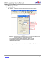
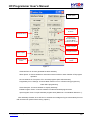
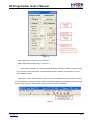
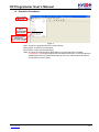
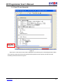
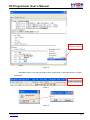
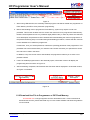
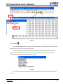
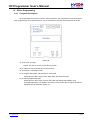
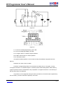
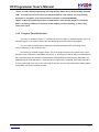
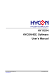
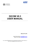
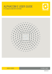
HY-Programmer User’s Manual . © 2008-2012 HYCON Technology Corp. www.hycontek.com APD-HYIDE004-V05_EN HY-Programmer User’s Manual Table of Contents 1. PROGRAMMING WINDOW.........................................................................................3 1.1 INTERFACE SETUP .............................................................................................................................. 3 1.2 OPERATION PROCEDURES ................................................................................................................... 6 1.2.1 Open File and Assembly ......................................................................................................................... 7 1.2.2 Download Hex File to Programmer or IDE Flash Memory ................................................................. 9 1.2.3 Read the Code from Flash Memory .................................................................................................... 10 1.3 PC ONLINE OTP PROGRAMMING ...................................................................................................... 11 1.3.1 Blank Check 1.3.2 Program 1.3.3 Verify ................................................................................................................................................ 13 1.3.4 Read ................................................................................................................................................ 13 1.3.5 AUTO ................................................................................................................................................. 14 1.4 .................................................................................................................................... 12 ........................................................................................................................................... 12 OFFLINE PROGRAMMING ................................................................................................................... 15 1.4.1 Program Description .............................................................................................................................. 15 1.4.2 Program Times Restriction.................................................................................................................... 17 . 1.5 INFORMATION BUTTON ...................................................................................................................... 18 1.6 ERROR MESSAGE ............................................................................................................................. 20 2. REVISION HISTORY..................................................................................................21 © 2008-2012 HYCON Technology Corp www.hycontek.com APD-HYIDE004-V05_EN page 2 HY-Programmer User’s Manual 1. Programming Window 1.1 Interface Setup Click “Options”, a window will appear. Click the interface setup, as shown in Figure 1. . Figure 1 Chip Select Choose the specific programming IC part no. If programmed IC differs from the selected IC, Blank Check, Program and Verify will fail. Language Choose operation interface language, like Chinese or English. Hardware Interface USB interface or Parallel Port interface is selectable. IDE Mode Program choosing. When interface setup finished, click “Build Options” to select programming configuration. As described in Figure 2. © 2008-2012 HYCON Technology Corp www.hycontek.com APD-HYIDE004-V05_EN page 3 HY-Programmer User’s Manual Build Option No Use Area Fill 00 or FF Generate Files Program Key Function SettingChoose Blank Function is On or Off Smart Compiler Program Protect Stack Option . Enable Program Times Input Program Times Figure 1 Generate Files Choose generated file after assembly Stack Option Choose whether to reset when stack overflow or stack full after OTP program operation. No Use Area Fill Fill up 00 or FF in unused program space after assembly. ProgramKey Func. Settings Choose blank function is on or off when using program key under offline programming. Smart Compiler Choose whether to simplify assembly. Enable Program Times Choose whether to enable download program times. Input Program Times Input download program times (Maximum: 2147483646. Minimum: 1). After assembly finished, click “ICE Test” to evaluate test voltage as Figure 3 described (Connect IDE and insert 9V power before clicking “Option”). © 2008-2012 HYCON Technology Corp www.hycontek.com APD-HYIDE004-V05_EN page 4 HY-Programmer User’s Manual Figure 2 . VPP voltage while programming: 5.6<VPP<6.6. VDD voltage while programming: 2.7<VPP<3.6. Click ”OSC Calibration” for starting Software/Hardware Calibration. Please note this function only can work on the programmer ”HY10000-WK05” with the software, HYCON-IDE V.3.0 and future updated version. Finally, click “Close” after the interface setup is done. All configured arguments will be recorded. If the configuration is opened next time, default value will be written in automatically and the selected programming IC part no. will be shown in topic window as Figure 4 described. Figure 3 © 2008-2012 HYCON Technology Corp www.hycontek.com APD-HYIDE004-V05_EN page 5 HY-Programmer User’s Manual 1.2 Operation Procedures Figure 4 Open Open the programmed source code main file. Open Project Open the saved project. Save Project Save the finished project. *Note: The original “Download file to Flash Memory” function has been cancelled. HYCON-IDE 3.0 no longer supports Hex File download function. If users would like to download the Hex File, please download it by HY-Hex Loader software and follow the guidance of user manual. . © 2008-2012 HYCON Technology Corp www.hycontek.com APD-HYIDE004-V05_EN page 6 HY-Programmer User’s Manual 1.2.1 Open File and Assembly . Figure 5 Open source code main file and it will be displayed as the assembly file. If the displayed name differs from main file, points the mouse to the specific file and presses mouse right key. Set this file as the assembly main file as shown in Figure 7. © 2008-2012 HYCON Technology Corp www.hycontek.com APD-HYIDE004-V05_EN page 7 HY-Programmer User’s Manual Click Mouse Right Key. Set Program Main File . Figure 6 Assembles Source Code and download the file to programmer or IDE Flash Memory, as Figure 8 illustrated. Figure 7 Figure 8 © 2008-2012 HYCON Technology Corp www.hycontek.com APD-HYIDE004-V05_EN page 8 HY-Programmer User’s Manual Figure 9 1. When using USB interface, the assembly finished program code will be loaded into programmer or Flash Memory of IDE for mass production programming. 2. Before downloading code to programmer Flash Memory, system may require to enter into password. This function enables users to monitor the code from PC to programmer Flash Memory. Please note that password can only include 6 digits (ASCII Code). In order to protect the code that users developed, the password must be entered before downloading the code into programmer. If the password entering step is cancelled during downloading procedure, it means that the code will not be allowable to be read from programmer. Furthermore, once you set the password, it will be the operating password of the programmer. This password has to be entered before you read the code. Please memorize your password to ensure the code can be read in the future. In addition, every time a new code is downloaded; the programmer will ask you to enter a new password afresh. . 3. If there is enabled program times in the assembly option, information column will display the programming times as shown in Figure 10. 4. After assembling completed, Hex filename and Checksum will be displayed in underneath section, as Figure 11 illustrated. Figure 10 1.2.2 Download Hex File to Programmer or IDE Flash Memory HYCON-IDE 3.0 no longer supports Hex File download function. If users would like to download the Hex File, please download it by HY-Hex Loader software and follow the guidance of user manual. © 2008-2012 HYCON Technology Corp www.hycontek.com APD-HYIDE004-V05_EN page 9 HY-Programmer User’s Manual 1.2.3 Read the Code from Flash Memory The function of “Read from Flash Memory” helps users to ascertain whether the code of programmer Flash Memory is the same with Download Code. The Password entered must in accordance with the Download Password, so the data will be revealed, as Figure 13 shown. . Figure 11 © 2008-2012 HYCON Technology Corp www.hycontek.com APD-HYIDE004-V05_EN page 10 HY-Programmer User’s Manual 1.3 PC Online OTP Programming Figure 12 Figure 13 Blank Check, Programming, Verify and Read Commands can be implemented when the programmed file being successfully loaded into programmer or IDE Flash Memory. On the contrary those commands will not be activated if the download failed. . Figure 14 Figure 15 Figure 16 Make sure the selected programming IC part number is the same with the OTP part number in the topic window as Figure 1 described. When programmer executes Blank Check, Programming and Verify commands, Program will check whether the IC part number and OTP programming part number are identical. If the part number is different, the data will not be written into OTP and an error message will be displayed in information column as Figure 16Figure 14described. If users intend to find out whether the part number is correct before programming, point the cursor to ”IC Connection Status Display” and click the mouse left key. If the selected IC is correct, a message will show up as Figure 17. If it is incorrect, the message will be displayed as Figure 18. If © 2008-2012 HYCON Technology Corp www.hycontek.com APD-HYIDE004-V05_EN page 11 HY-Programmer User’s Manual “Enable Program Times” has been marked up, the spare program times will display in the message column as illustrated Figure 19Figure 17. Figure 17 1.3.1 Blank Check The internal code of Blank ICs that have yet been programmed is 0xFFFF. The purpose of checking the IC is to make sure the OTP address content is 0xFFFF. If the IC selection is correct and the content is empty, a message will appear as Figure 18 If the IC selection is incorrect or the content is not empty, a message will show up as Figure 21 described. . Figure 19 1.3.2 Program The purpose of programming is to write Compiler accomplished program into IC OTP. When programming is completed and the IC is assembled as finished goods, programmer can operate the program as users commanded. Program the downloaded or assembly finished Hex file (displayed at the bottom of the column) in the selected IC and verify the correctness of the programming content (please refer to Chapter 1.2.1 or 1.2.2 for programming procedures). If the selected IC is correct and the programming succeeds, message will appear at the information column as Figure 22 illustrated. If “Enable Program Times” is ticked up, the enable program times will minus 1 and the program times left will be revealed in the message column. © 2008-2012 HYCON Technology Corp www.hycontek.com APD-HYIDE004-V05_EN page 12 HY-Programmer User’s Manual Figure 20 If the IC selection is incorrect or the programming fails, a message will show up as Figure 23. Figure 21 1.3.3 Verify The purpose to verify programming IC is to compare if the program written into IC OTP equals to the program downloaded to programmer or IDE Flash Memory. Verify programming IC content consistency with the downloaded or assembled Hex file (displayed at the bottom of the column). If the IC is protected by program, this verification is ineffective or the comparison failed. . If IC selection and program verification is success, a message will appear as Figure 24. Figure 22 If IC selection is incorrect or the program verification miscarries, a message will pop up as Figure 25. Figure 23 1.3.4 Read The purpose to read the IC is to verify the consistency of OTP Checksum and programmed Hex file. To read IC content, the procedures are illustrated as Figure 26. Its content will reveal at ”Display Code” window. © 2008-2012 HYCON Technology Corp www.hycontek.com APD-HYIDE004-V05_EN page 13 HY-Programmer User’s Manual OTP Type Checksum Figure 24 . 1.3.5 AUTO Auto integrates Blank Check, Program and Verify function. If user selects Auto, it will first check whether the IC is blank, then to program and verify. After the execution succeeded, a message will be displayed as Figure 27 displayed. If the option, ”Enable Program Times” is ticked up, the program permitted times will reduce 1 and the program times left will be shown in the message column. Figure 25 If any function fails, the whole process will stop and display an error message in the message column. © 2008-2012 HYCON Technology Corp www.hycontek.com APD-HYIDE004-V05_EN page 14 HY-Programmer User’s Manual 1.4 Offline Programming 1.4.1 Program Description As the development process evolves to mass-production, the programmer can be used alone when programming on the production line. It is not necessary to connect the programmer to the PC. . Figure 26 J1 DC Jack, 9V input. *Notice: the case is 9V; the core is Ground (VSS). U6 USB port, users use this port to connect to PC. J3 IDE port, connecting HY-ICE. P3 Program PIN output. PIN and OTP is connected. Output pin from left to right is VSS, VDD, SDO, SDI, SCK and VPP. P5 Extend programming port. Output pin from left to right is Green LED, Red LED, Blank Check Button, and Programming Button. For detailed connecting circuit, please refer to Figure 29 and the definition can be referred to Figure 30. © 2008-2012 HYCON Technology Corp www.hycontek.com APD-HYIDE004-V05_EN page 15 HY-Programmer User’s Manual Figure 29 . Figure 30 L1 Success message light display, green LED. L2 Error message light display, red LED. S1 Program button, for offline program operation. S2 Blank Check button, for offline operation. S3 Information button. To implement offline operation, Hex file must be firstly downloaded to programmer Flash Memory. S2 Button can check if the IC is blank. S1 Button is programming button. Its procedures are: Blank Check Program Verify. If ”Program Protection” of “Assemble Option” is ticked up before downloading data to Flash Memory, program protection will be executed after Verify completed. If ”Program Protection” is not ticked up, it will stop after Verify accomplished. If any failure or error happened during execution procedures, L2 Red LED will be lightened up. On the contrary, L2 Green LED will be lighted up if success. © 2008-2012 HYCON Technology Corp www.hycontek.com APD-HYIDE004-V05_EN page 16 HY-Programmer User’s Manual *Notice 1: Under offline programming, the programming status can be determined by checking LCM. If check sum has been shown on LCM and LCM has stop working, the programming procedure is completed. (This issue has been corrected on HY10000-WK02B) *Notice 2: When programming function is implemented, make sure 9V adapter is connected before connecting USB line. Do not plug out 9V Adapter whist PC operating, or else it may result in PC crash. 1.4.2 Program Times Restriction The menu of ”Assemble Option” in interface setup has an option of ”Enable Program Times” as described Figure 2. This option restricts the permitted program times of download program. This is a safety mechanism that restrains the permitted program times, preventing it from over-programming on the production line. After ticking up ”Enable Program Times”, key in the program times in the column below ”Input Program Times” (maximum is 99999999, minimum is 1). This argument will be written into EEPROM of the programmer after the compiler programmed file is downloaded to Flash Memory. Afterwards, the enabled program times will reduce 1 each time when programming completed. If the value reduced to 0, the programming action may not be executed. At this time, an error signal (Red LED) will be lighted up but Blank Check still operates normally. © 2008-2012 HYCON Technology Corp www.hycontek.com . APD-HYIDE004-V05_EN page 17 HY-Programmer User’s Manual 1.5 Information Button Press Information button, displaying HYCON IDE message Press Information button again, displaying Program Counter Times message 1. If Program Counter Times is enabled. 2. If Program Counter Times is disabled. . Press Information button again, displaying VDD and VPP voltage. Press Information button again, OTP ID and Flash stored ID. Press Information button again, displaying error message. 1. If there is no error message. 2. If there is error message. © 2008-2012 HYCON Technology Corp www.hycontek.com APD-HYIDE004-V05_EN page 18 HY-Programmer User’s Manual Press Information button again, displaying if the blank function is enforced when using program key 1. If the blank function is on. Information 5: Program Key Fun. Wait for 1 second B+P+V B:blank, P:program, V:verify 2. If the blank function is off. Information 5: Program Key Fun. Wait for 1 second P+V P:program, V:verify . © 2008-2012 HYCON Technology Corp www.hycontek.com APD-HYIDE004-V05_EN page 19 HY-Programmer User’s Manual 1.6 Error Message VDD Error VPP Error OTP ID Error Blank Fail Program Fail . Verify Fail Protect Fail Program Counter left zero © 2008-2012 HYCON Technology Corp www.hycontek.com APD-HYIDE004-V05_EN page 20 HY-Programmer User’s Manual 2. Revision History Major differences are stated thereinafter: Version Page V01 ALL V02 8 15-16 V03 3-5 V04 17-18 V05 ALL Revision Summary First edition Add the description of password. Add the description of P5-Extend programming port. Update the figures and add the description of ”OSC Calibration”. Add a note for attention when offline programming. Add the description of blank check function and related information Delete the description of downloading hex file to programmer from HYIDE. . © 2008-2012 HYCON Technology Corp www.hycontek.com APD-HYIDE004-V05_EN page 21