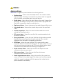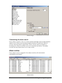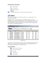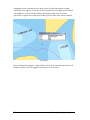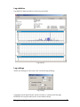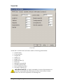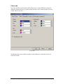
1
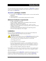
SmArt
Nav
intelligent navigation
Users manual
v2.7
www.cvs.hr
March, 2008.
INTRODUCTION...................................................................................................... 1
SmArtNav package contents.................................................................... 1
Minimum hardware requirements ........................................................................... 1
Installation ................................................................................................................... 1
USING THE NAVIGATION SYSTEM ...................................................................... 3
Application status and information panel adjustment ........................................ 4
Moving the chart ....................................................................................................... 4
Main toolbar buttons................................................................................................. 5
Vessel tracking mode................................................................................................ 5
Routes.......................................................................................................................... 6
Creating a new route ...................................................................................... 6
Updating routes................................................................................................ 7
Waypoints ................................................................................................................... 9
Find by name ........................................................................................................... 11
Find geographic position........................................................................................ 11
Changing scale ....................................................................................................... 12
Alarms........................................................................................................................ 13
Alarm settings.................................................................................................. 13
Alarm archive ................................................................................................. 14
Logging ..................................................................................................................... 15
Printing chart ............................................................................................................ 18
Settings ...................................................................................................................... 18
Application settings ....................................................................................... 18
Symbol settings ............................................................................................... 26
Time synchronization...................................................................................... 26
Clear boat track............................................................................................. 26
Color scheme ................................................................................................. 26
Nautical appendix................................................................................................... 27
MOB (Man Over Board).......................................................................................... 28
ALARMS ................................................................................................................ 29
ARPA (RADAR) DEVICE ...................................................................................... 30
DATABASE............................................................................................................ 32
Displaying database information .......................................................................... 32
Lighthouses, buoys and other nautical marks ..................................................... 33
CONNECTING VESSEL DEVICES ....................................................................... 34
Connecting the GPS device .................................................................................. 34
Connecting the autopilot....................................................................................... 35
KEYBOARD SHORTCUTS ................................................................................... 37
NOTES ................................................................................................................... 38
Introduction
This users manual provides some basic information on SmArtNav navigation
system and its components installation procedure and later on it deals with
the usage of the SmArtNav.
SmArtNav package contents
•
•
•
CD medium with SmArtNav navigation system, vector charts and the
Database
This users manual
HASP dongle USB - unauthorised usage protection system
Minimum hardware requirements
-
PC/IBM compatible computer
Pentium 600MHz, 128MB of RAM and 400MB of free disk space
Graphic resolution 800×600 or higher
RS232 serial or USB port with adequate USB -> serial converter
Additional serial or USB ports for connecting other marine instruments
or NMEA concentrator
Microsoft Windows 98/Me/NT/2000/XP/Vista operating system
Microsoft Internet Explorer v5.0 or higher
Installation
Prior to installing the SmArtNav system user must assure that adequate
operating system and Internet Explorer are preinstalled.
IMPORTANT NOTICE:
The user will not be able to launch the SmArtNav navigation system
if HASP key is not connected to the computer. HASP key and its
documentation are copyrighted property of the Aladdin
Knowledge systems Ltd.
-
Connect HASP key to the computer
-
Run the "Setup" program located on your installation CD. That will
start the installation procedure in form of the installation wizard. The
wizard will guide you through the rest of the installation procedure.
-
After successfull instalation restart the computer
The installation procedure will automatically create a new program group
and desktop shortcuts according to the version of the navigation system
that was purchased.
After the installation and the SmArtNav is started for the first time, it is very
important to adjust some parameters in order to make the SmArtNav
system work correctly. Those parameters are e.g. vessels length, width,
Introduction
1
height, draft, displacement etc. and are set on the vessel tab of the
application settings dialog box. For more information concerning this
subject look at Application settings section of this manual.
IMPORTANT NOTICE:
HASP key represents a standalone product.
Therefore if the key somehow get lost, the vendor is
not bound to supply another one.
If the key is accidentaly damaged, the vendor will substitute the
damaged key with the new one for the price of new one..
2
Introduction
Using the navigation system
SmArtNav user interface
SmArtNav user interface is divided into two basic portions which are as
follows: vector chart, application status and information panel.
Scale
•
Current scale
Satellite status
•
•
•
•
GPS satellite signal intensity
Number of satellites detected
Calculated GPS position error (Garmin units only)
Satellite position on sky after click on blue question mark (?)
Cursor
•
•
UTC date and time (UTC = Universal Time Coordinated)
Vessel date and time (LCL = Local)
Using the navigation system
3
•
•
•
•
•
•
Cursor position sunset and sunrise time
Moon phase
Cursor longitude and latitude
Cursor course from boat (CFB)
Distance between cursor and vessel expressed in nautical miles
Current speed ETA (ETA = Estimated Time of Arrival)
Vessel
•
•
•
•
Vessel position (longitude and latitude)
Vessel course (COG = Course Over Ground)
Vessel speed (SOG = Speed Over Ground)
Travelled distance
Depth
•
•
Depth (DPT = Depth)
Depth bellow keel (DBK = Depth Bellow Keel)
Wind
•
•
Vessel relative wind direction
Vessel relative wind speed
Sea
•
•
•
•
Vessel speed through water (STW = Speed Through Water)
Water temperature
Travelled distance
Relative travelled distance
Mini chart
•
Chart with a little square indicating the displayed portion of the chart
Application status and information panel
adjustment
The application status and information panel is adjustable in several ways.
Firstly, there is a possibility to choose which subpanels will be visible and
which won't. One can simply right click the main status and information
panel which makes the pop up menu to appear. This menu allows the user
to switch on/off individual subpanels and also to choose which side the
panel resides on. Vertical subpanel arrangement can be changed by
dragging subpanels up and down (drag&drop holding the caption bar).
Moving the chart
There are three ways to move/scroll the chart. These are as follows:
•
•
•
4
Drag and drop in any direction desired
Left click on the mini map
Simply by pressing the keyboard cursor keys
Using the navigation system
Main toolbar buttons
Vessel tracking mode
Managing routes and waypoints
Managing individual locations (fishing spots, men over board)
Find by name (cities, places, rivers, gulfs etc.)
Find by geographic position
Customize alarm settings
Customize log file and logging
Print chart
Application settings
Appendix
MOB (Man Over Board)
Vessel tracking mode
Vessels position is indicated by a red trinagle whose tip indicates vessels
bow position. Triangles orientation indicates vessels movement direction.
Triangles size is constant and is not in any way related to vessels real size. If
the Show vessel trace check box (located on the View tab in the main
setup dialog box) is checked then the blue dotted line will be drawn
behind the vessel.
Vessel symbol
Tracking mode button (first in the row) is used to switch between the
following tracing modes:
•
•
Free - Vessels movement does not affect the chart
Follow - the chart is scrolled automatically so the vessel always
remains in the center
Using the navigation system
5
Routes
The SmArtNav navigation system allows the user to set the route that the
vessel will automatically navigate by. In order to make use of this feature
the vessel should, beside a GPS, be equipped with an appropriate NMEA
compatible autopilot device.
Creating a new route
One can create a new route by right clicking anywhere on the chart
(except ground or shallow sea). The spot you have clicked on will be used
as your starting waypoint. The other waypoints are marked by left clicking
anywhere on the chart (except ground or shallow sea). The number of
aypoints is unlimited. Routes ending waypoint is placed by double clicking
the left mouse button or by pressing the Enter key on your keyboard. When
you are done setting waypoints, the dialog box will appear asking you to
enter your routes name which is obligatory and also the name of starting
and ending waypoint which is optional.
Creating new route
To abort drawing current route simply press Esc key on your keyboard or
click the right mouse button.
6
Using the navigation system
Updating routes
Click the Routes button on main toolbar to brings up the routes dialog box.
This dialog is the central location for managing routes.
Update routes
Left side contains complete list of created routes and right side of the
dialog shows list of waypoints that make selected route. If there are no
routes selected waypoint list will be empty. There is a possibility to
show/hide routes. Little check mark next to routes name indicates if the
route is visible or not and can be turned on/off.
Every waypoint is determined by its geographic coordinates, course,
distance between it self and the previous one, ETA and fuel consumption.
Route commands
Edit route properties: name, first and last waypoint name and
route color
Reverse route
Delete route
Show/hide route
Find route
Print route
Activate the autopilot and navigate by selected route
Using the navigation system
7
Route waypoint commands
Insert waypoint
Edit waypoint properties: name and geographic position
Delete waypoint
Find waypoint
Activate the autopilot and navigate toward selected waypoint
Customize waypoint display (without label, name label or
number label)
When the autopilot is activated, it automatically finds the nearest waypoint
(in relation to vessels current position) and suggests to navigate toward that
waypoint. If calculates the routes closest waypoint and offers it as the
starting waypoint. There is still a posibility to navigate towards any other
waypoint by simply selecting the desired waypoint in the waypoint list and
activating the autopilot.
There is a possibility to change individual waypoint position by a simple
drag 'n' drop procedure. The routes dialog box has to be opened in order
to change waypoint poition in that way. Only then it is possible to drag the
waypoints around.
An example of waypoint drag 'n' drop
There is a possibility to enter waypoint geographic position in two different
formats: WGS84 and Mercators projection - Bessels ellipsoid (official charts
made by Croatian Hydrographic institute in Split). This is done in waypoint
properties dialog box.
Edit waypoint properties
8
Using the navigation system
Waypoints
SmArtNav navigation system features creating and editing individual
waypoints. Individual waypoints can be used to mark some interesting
places or sites like e.g. good fishing spots, diving locations, anchoring
places, dangerous locations etc. Every individual waypoint has its little icon,
name and description.
Updating waypoints
Individual waypoints are organised into groups. Every one of this groups
can contain an infinite number of waypoints. There is a possibility to
show/hide waypoint groups as well as the waypoionts.
Waypoint group commands
Create a new waypoint group
Change waypoint group name
Delete the selected waypoint group and all its waypoints
Individual waypoint commands
Create a new waypoint
Edit waypoint properties: name, icon, position and description
Delete waypoint
Print waypoint list
Find waypoint
Activate the autopilot and navigate toward selected waypoint
Using the navigation system
9
When in waypoint creation mode the cursor turns to a small cross and then
it is required to select location for the waypoint simply by clicking the
desired spot on the chart. After marking the location for the waypoint, a
dialog box appears that allows the user to select an icon and name for the
waypoint.
Waypoint properties
Individual waypoints can be moved to another group by a simple drag 'n'
drop procedure. Just pick a waypoint and drag it to a different group
(same as editing route waypoints described earlier).
Waypoints are represented by a small icons on the chart and are in some
way interactive. This means that one can click its symbol which will bring up
the waypoint information window.
Waypoint information
10
Using the navigation system
Find by name
SmArtNav navigation system features instant find by name procedure
which allows the user to find any object on the map by its name (cities,
places, rivers, gulfs…). The feature is activated by clicking the NAME button
on the main toolbar which will cause the following dialog box to appear:
Find by name
When Find by name window has appeared simply type the name of the
object or view a complete list of objects by unfolding the dropdown list.
When the desired location is marked click the Find button or press Enter.
Searched object will be immediately displayed in the middle of the screen.
There are nine types of objects that can be found by their name:
•
•
•
•
•
•
•
•
•
Cities: font color is black, all caps
Smaller cities and other places: font color is black, small caps
Airports, hydroelectric power plants: dark gray
Large and larger islands: purple font, all caps
Smaller islands: purple
Shallows: dark blue
Passages, channels, and gates: dark blue, all caps
Mountain tops, plains and alike: brown purple
Other: gray
Find geographic position
Another feature is finding the geographic position. Bring up the Find
position dialog box by clicking the POS button on the toolbar. When the
dialog box appears enter longitude and latitude and click the Find button
or press Enter. The desired position will be shown in the center of the screen.
Find by geographic position
You can enter geographic coordinates in two formats: WGS84 and Bessel.
Using the navigation system
11
Changing scale
Vector chart can be displayed in different scales: from 1000 up to 8.000.000
Current scale can be changed in several different ways:
•
•
•
Right click the current scale display on the main status-info panel
and then simply choose the desired scale from the pop-up menu
By keyboard shortcuts (see the keyboard shortcuts section)
By scrolling the mouse button
Changing scale
12
Using the navigation system
Alarms
Alarm settings
SmArtNav navigation system features the following alarms:
•
Shallow alarm – Warns when the depth below the vessel is smaller
than specified. The alarm is functional only if the vessel is equipped
with the NMEA compatible depth sounder device.
•
Depth alarm – Warns when the depth below the vessel is larger than
specified. The alarm is functional only if the vessel is equipped with
the NMEA compatible depth sounder device.
•
High speed alarm - Warns when speed exceeds the specified value
•
Low speed alarm - Warns when speed drops under the specified
value
•
Anchor drag alarm – Warns the user that the vessel has moved
outside the specified radius
•
Off-course alarm – Warns the user that the vessel exceeded route
deviation tolerance
•
Strong wind alarm – Warns the user that the wind speed exceeded
the specified value. The alarm is functional only if the vessel is
equipped with the NMEA compatible wind sensor.
•
GPS Alarm – Warns the user that the GPS communication error
occurred. There is a number of reasons for this type of error to occur
but the most common reasons are GPS power supply failures, bad
communication parameters, bad wiring, low signal etc...
•
Depth sounder alarm – Warns the user that the depth sounder
communication error occurred
•
Wind sensor alarm – Warns the user that the wind sensor
communication error occurred
•
Radar target nearness alarm – Warns the user that the vessel has
come to close to the radar target. The alarm can function properly
only if the vessel is equipped with the appropriate radar device
(ARPA-MiniARPA and NMEA)
Using the navigation system
13
Alarm settings
Customizing the alarm sound
Every alarm consists of an on-screen textual message and an appropriate
alarm sound. There are several predefined alarm sounds that can be
chosen from the alarm name field. Other sounds can be chosen by
browsing for other sound files on local or remote hard drive. The alarm
sounds can be played once or in loop mode.
Alarm archive
Every alarm event is logged in the alarm archive with all related
parameters and status.
Alarm archive
14
Using the navigation system
Alarm archive commands
Find location
Print archive
Delete archive
NOTICE:
For more information on alarms see the Alarms section
Logging
The purpose of logging is to make the evidence of vessels status over a
given period of time.
Logging service is always active and it handles recording of various
parameters over a specified stages of trip. These parameters are date and
time, geographic position, speed (SOG), course (COG), depth and wind
data. The period is defined in the amount of nautical miles or meters and
can be set in Log settings dialog box.
Logging route
Left portion of the log window contains the list of all existing log files and the
right portion contains a list of all log records with belonging parameters.
After defining the period click the Find button.
Log commands
Redraw route from log
Find route waypoint
Print log
Log statistics
Log settings
Using the navigation system
15
Logging service is always active and every day the navigation system
creates a new log file. Currently active log name file is typed bold. There is
a possibility to automatically delete all log files older than the date
specified. Log files are named according to the date they were created.
Log display
Every displayed Log point is selectable. Left click on the selected point will
display window with all logged information for that point.
16
Using the navigation system
Log statistics
Log statistics demonstrates chosen log summary.
Log statistics
Log settings
Within this dialog box the user can customize log settings:
Log settings
Logging interval (specified in nautical miles or meters) sets the gap
between two log records (a set of recorded values).
Using the navigation system
17
Printing chart
SmArtNav features a possibility to print currently displayed portion of the
chart with all related data (time, date and vessels geographic position).
Settings
After installing SmArtNav it is required to configure vessel paramters and
controllers for proper functionality. Application settings is done in the
Application settings dialog box which can be accessed by clicking the SETT
button located on the main toolbar.
Application settings
Application settings dialog box contains the following tabs:
•
•
•
•
•
•
•
18
Vessel
View
Colors
Controllers
Devices
GSM modem
Activation
Using the navigation system
Vessel tab
Vessel tab
Vessel tab contains the text boxes used for following parameters:
•
•
•
•
•
•
•
•
•
•
•
Vessel name
Licence plate
Length (m)
Width (m)
Height (m)
Displacement (t)
Draft (m)
Maximum speed (kt)
Travelling speed (kt)
Fuel consumption (l/h)
Fuel tank capacity (l)
IMPORTANT NOTICE: It is highly advisable to enter all parameters as
precisely as possible because many further calculations is done
based on the data supplied in this dialog box..
Using the navigation system
19
View tab
This tab contains view customizing controls.
View tab
This tab provides the following options to be customized:
20
•
Fast scrolling - This option can improve chart rendering speed
•
Flashing lighthouses - toggles flashing lighthouses on/off
•
Vessel trace - toggles vessel trace on/off
•
Show log - toggles vessel log on/off
•
Forbid route over ground - This option is used during the route
creation process and should always remain turned on except when
doing some measurement over ground.
•
Detect special areas – toogles Special areas warning after entering
them (forbidenn anchoring, explosive materials…)
•
Show scale – toogles on/off on chart scale display
•
Grid – toogles on/off on koordinate grid display
•
Vector – toogles vessels direction vector display (time component
must be entered). If enabled, vector with variable length (depends
upon the vessels speed) will be shown in front of the vessel.
•
UTC to LCL time offset - Universal time coordinated offset. This is used
when calculating local time in relation to the UTC time.
•
Active language – toogles between posible languages
•
Long/Lat display mode - Choose between the Long/Lat format
Using the navigation system
Colors tab
This tab contains controls that allow the user to chose different colors for
different objects like e.g. vessel symbol border color, vessel symbol fill color,
vessel trace color etc.
Colors tab
Standard map colors option enables chart display in standard colors for
nautical charts.
Using the navigation system
21
Controllers tab
Communication controllers are set in this tab. Communication controller
can be either a serial port or a TCP/IP connection, both handling inbound
and outbound traffic.
Serial port parameters:
• Port – serial port number which the NMEA device is connected to
• Baud rate - Communication speed. According to NMEA-0183
standard, communication speed has to be set to 4800 baud.
• Data bits - Standard value is 8
• Parity – Standard value is no parity
• Stop bits - Standard value is 1
TCP/IP connection parameters:
• Port - TCP/IP port number that the navigation system communicates
through with the remote computer or computers. 8099 is standard.
• Destination IP addresses - A list of IP addresses that the navigation
system communicates with. This option is enabled only if the data
transmission over the controller is enabled.
Common parameters:
• Listener sentences - enables data reception and provides the
possibility to choose which sentences the controller will process. If the
data reception is enabled, the received data will be processed by
the program or forwarded to another listener device or service.
22
•
Talker sentences - enables data transmission and provides the
possibility to choose which sentences the controller will send to
another device or service. If the talker is enabled the valid sentences
will be transferred to another device connected to the controller.
Messages that need to be sent have to be selected or checked in
the list of available messages.
•
Interval (ms) - Time gap between two messages. This option is active
only if data transmission is active. When working with serial
connection, recommended interval is between 1000 and 2000ms
and in case of TCP/IP connection recommended interval is 200ms. If
the interval is too small, communication congestion is likely to occurr.
•
NMEA prefix - The NMEA prefix determines how the controller
represents it self to other NMEA devices. Typical NMEA prefix is "GP".
Using the navigation system
Controller tab
The status panel contains the following information:
• Reception (RxD), transmission (TxD) indicators, activity indicator
• Number of NMEA messages sent and received
• Number of bytes sent and received
Typical navigation system configuration:
NavPro
GPS
VJETAR
DUBINOMJER
COM1
COM2
COM3
Create three serial port controllers on computer A and enable reception of
all messages.
NavPro
GPS
VJETAR
DUBINOMJER
A
NavPro
B
COM1
COM2
COM3
TCP/IP
Create three serial port controllers on computer A and enable reception of
all messages. It is also required to create one outbound traffic TCP/IP
controller. Destination address is IP address of the destination computer (B).
Using the navigation system
23
On computer B create one TCP/IP inbound traffic and enable reception of
all messages.
NavPro
GPS
A
NavPro
COM1
COM2
VJETAR
B
COM1
DUBINOMJER
TCP/IP
On computer A create two serial port controllers and enable reception of
all messages. Also create one TCP/IP controller both inbound and
outbound traffic enabled. Destination address is IP address of the
destination computer (B).
On the destination computer (B) create one data receiving serial
controller. Also create one TCP/IP controller both inbound and outbound
traffic enabled. Destination address is IP address of the destination
computer (A).
NavPro
GPS
VJETAR
DUBINOMJER
A
COM1
COM2
COM3
NavPro
B
COM1
VHF DSC
TCP/IP
Create three serial controllers on computer A and enable reception of all
messages. On the same computer create one outbound traffic only TCP/IP
controller with the destination address of computer B.
Create one TCP/IP inbound data only controller on computer B and enable
reception of all messages. It is also required to create one outbound traffic
only serial controller. In the list of available messages to be sent choose only
GGA, GLL and RMC messages
IMPORTANT NOTICE:
SmArtNav navigation system can work in the simulation mode too.
The simulation mode is activated by clicking the "Settings /
Simulation / Active" button located on the applications main
toolbar. The simulation mode can be used to learn how to use the
program or for presentation purposes. Everything that happens in
simulation mode is not in any way related to vessels real position,
speed or direction. All values and vessel movement when in the
simulation mode are randomly generated computer values..
24
Using the navigation system
Devices tab
This tab provides space for the user to specify parameters of devices
connected to the computer.
Devices tab
•
•
GPS – GPS antenna position from vessels bow and port side. This is
used to correct vessel position on the chart.
Autopilot
o Controller – An outbound controller through which the data will
be sent to the autopilot. The controller list contains controllers
created in the Controllers tab of the same dialog box.
o Waypoint radius – Waypoint radius determines the radius
around waypoints. When the vessel reaches the circle around
the waypoint, the navigation system will consider that the
waypoint is reached and direct the vessel toward next
waypoint if it exists.
•
Wind sensor
o Angle correction - corrects the wind angle value. the specified
value can be negative.
•
Depth sounder
o Transducer position - Probe depth. This parameter is required in
order to calculate the depth below the vessel and depth
below keel.
Using the navigation system
25
Symbol settings
Settings/Symbols button brings up the Symbols dialog box which allows the
user to chose among many symbols available in chart display system. These
symbols can be either visible or not. There is a separate symbols settings for
each scale which means that the SmArtNav navigation system remembers
which symbols are visible on every separate scale.
Symbol settings
Every symbol located in this dialog box can be marked visible or not for
current scale. When selection is done it is required to click the Apply button
on the toolbar in order to save symbols settings. There is also a possibility to
set a default setting. Default setting consists of a number of symbols that will
be visible and is same for each scale.
Time synchronization
If there is a GPS connected to the computer, there is a possibility to
synchronize system time with GPS time.
Clear boat track
Deletes current boat track.
Color scheme
The navigation system has several predefined color schemes to chose
upon. A standard color scheme is appropriate during daytime and there
are also some darker schemes that can be used during the night.
26
Using the navigation system
Nautical appendix
SmArtNav Nautical appendix contains various manuals and information
that have proven themselves to be very handy while sailing.
SmArtNav Nautical appendix
Using the navigation system
27
MOB (Man Over Board)
MOB feature is used to quickly mark the spot where e.g. the crewman or
the passenger has fallen into sea. When MOB is activated, the flashy mark
looking like this appears on the chart:
MOB mark
Upper left corner of the screen contains a little panel with detailed MOB
information:
MOB information
•
•
•
Position - Geographic MOB position
Course - Course needed to arrive at the MOB position
Distance - distance from MOB
The red triangle displays vessels movement direction related to MOB
position. If the triangle is pointing downwards then the vessel is moving
away from the MOB position
28
Using the navigation system
Alarms
SmArtNav navigation system monitors all relevant sailing parameters and
according to these values it is able to sound and alarm.
Every alarm can be in one of the following states:
•
•
•
Activated
Deactivated
Acknowledged
When an alarm goes off, an appropriate sound is played and the Active
alarms window appears showing the list of currently active alarms.
Active alarm list
User must acknowledge every active alarm for turning off the alarm sound.
When all active alarms have been confirmed, the Active alarms dialog box
turns off. There is alarm warning sign in the upper left screen corner. If the
alarm is active and not confirmed warning is flashing. Clicking the warning
sign brings up the Active alarms dialog box.
Alarm warning sign
If the alarm is related to main panel displayed value, this value will change
color to flashing red until the alarm is acknowledged or deactivated.
Alarm indication
All alarm events are automatically logged.
Alarms
29
ARPA (radar) device
SmArtNav navigation system provides a possibility to receive data from
ARPA radar subsystem connected to the computer which means that it
supports display of the radar target on the chart.
ARPA target
Our vessel
Radar cursor
It also shows the radar cursor position which can be useful if there is a
problem with radar picture visibility. In that kind of situation it is required to
click the unknown target object and look upon its position on the chart.
When a radar target is clicked, the navigation system will show some
additional information about the target, targets movement parametes and
also a vessel and its movement parameters.
30
ARPA (radar) device
Vessel movement direction
Target information
ARPA (radar) device
31
Database
SmArtNav navigation system contains a very detailed nautical database
which contains a great number of pilot information, pictures, sailing
instructions, chart plans etc.
NOTICE:
The SmArtNav database is under construction all the time because
it is not possible to collect all the relevant information about all
locations. Therefore, we want to use this opportunity to politely
appeal on the user to inform us about all incorrect information he
encounters and also to inform us about the information he finds
important but not mentioned. Thank you in advance !
Displaying database information
Some chart object captions are clickable and they behave similarly to
hyperlinks in web browsers which means that they react on mouse over
event by changing caption color to red and becoming underlined. If the
object caption turns to red that means that there is some information on
that object in the database. Now, it is only required to click the caption to
bring up the database window and read the information on the object.
Database information example
Every object can be related to an another object or to a number of
objects. If these connections exist, they are displayed in the left portion of
the database window. E.g. database information window on an island will
also make available database information on all the cities and places
located on the island in a hierarchical manner.
32
Database
The database consists of five separate parts. These are as follows:
•
•
•
•
•
Pilot data
Common dana and touristic information
Historical information
Plans
Photographs
Lighthouses, buoys and other nautical marks
Lighthouse, buoy and beacon objects contain all relevant information.
Lighthouse and buoy information example
Additional information concerning object type and appearance can be
found in the SmArtNav Nautical appendix.
Database
33
Connecting vessel devices
Connecting the GPS device
In order to make the SmArtNav navigation system fully functional, it is
required to connect a GPS device to the computer. The GPS device has to
be NMEA 0183 communication standard compatible. Connecting is done
in a few simple steps:
1. GPS device has to be set up to transmit data in WGS 84 format and
communication parameter has to be set to No IN / NMEA OUT.
According to the NMEA 0183 communication standard (v2.0 or later),
standard parameters are as follows: 4800 baud (bd), 8 bit, 1 stop bit,
no parity. For more information on GPS device settings read the GPS
device users manual.
2. Port number parameter has to be set to port which the GSP device is
connected to and port speed has to be set to 4800 baud (bd). This is
done when creating or editing a controller.
3. GPS is connected with PC in the follwing way:
•
GPS Data GND connect to PC Data GND (pin 5 on RS 232 DB9)
•
GPS NMEA Out connect to PC Data In
•
Shield - It is recommended to connect the Shield labeled wire
with vessel grounding
•
Secure the connections by soldering and insulating
PC kabel
Data In
GND
NMEA Out
GPS kabel
GND
GPS and PC cable connection scheme
Shortly after connecting is done, the data transmitted by the GPS device
should be read, processed and displayed by the SmArtNav navigation
system. There isn't any danger for the computer or the GPS device if the
wires somehow get mixed up or connect wrongly.
34
Connecting vessel devices
Connecting the autopilot
Additional cable is required for connecting the autopilot to the computer.
It is required to connect an autopilot device to the computer in order to
make use function that the SmArtNav navigation system provides.
Autopilot must be NMEA 0183 compatible. Connecting is done in a few
simple steps:
1. Autopilot device has to be set to receive data in WGS 84 format and
the communication parameter has to be set to No IN / NMEA OUT.
According to the NMEA 0183 communication standard (v2.0 or later),
standard parameters are as follows: 4800 baud (bd), 8 bit, 1 stop bit,
no parity. Detail information can be found in Autopilot User Manual.
2. Autopilot controller port parameter has to be set to port which the
autopilot device is connected to. Port speed is 4800 baud (bd).
3. Autopilot is connected to PC cable in the following manner:
PC
Data OUT
GND
IN
OUT RS232
12V
GND
RS422
NMEA IN
GND
GND
12V
Autopilot
Akumulator
Autopilot and computer connection scheme
PC
Data IN
Data OUT
GND
NMEA OUT
GND
GPS
IN
OUT RS232
12V
GND
RS422
NMEA IN
GND
GND
12V
Autopilot
Akumulator
Autopilot, computer and GPS connection schme (over the same port)
Connecting vessel devices
35
4. Autopilot has to be set to AUTO + TRACK MODE.
Shortly after connecting is done, the data transmitted by the SmArtNav
navigation system should be read by the autopilot device. There isn't any
danger for the computer or the autopilot device if the wires somehow get
mixed up or connect wrongly.
The RS232/RS422 adapter is provided on demand.
36
Connecting vessel devices
Keyboard shortcuts
Main interface
Cursor keys .......................Move chart
Shift + Cursor keys............Move cursor
Left Mouse Button ...........Object information
LMB + move .....................Move chart
Right mouse button ........Create new route
Space bar ........................Center vessel on screen
Ctrl+Shift ...........................Show all database objects
F1.......................................Help
F5.......................................Refresh screen
F7.......................................Zoom in
F8.......................................Zoom out
Ctrl+Q ...............................Add current location
Ctrl+P ................................Print chart
Ctrl+F.................................Find by name
Ctrl+G ...............................Find geographic position
Ctrl+T.................................Toogle tracking modes
Updating routes, waypoints and logs
Ins ......................................New record
Del.....................................Delete record
Enter..................................Find record on chart
Alt+Enter ...........................Edit record
Ctrl+S.................................Show/Hide
Ctrl+P ................................Print
Keyboard shortcuts
37
Notes
SmArtNav team wishes you a calm sea!
38
Notes