1
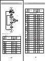
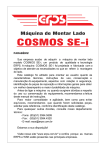
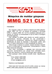
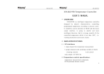
ELE INTELLIGENT TEMPERATURE AND
HUMIDITY
CONTROLLER
USER
MANUAL
Guangdong Chico Electronic Inc.
Contact person : Jim Ye . [email protected] T: +86 13590671032
ELE INTELLIGENT TEMPERATURE AND HUMIDITY CONTROLLER
ELE INTELLIGENT TEMPERATURE AND HUMIDITY CONTROLLER
USER MANUAL v 1.0
Thanks for choosing the Intelligent temperature and humidity controller
of our company. In order to convenient you to buy and use the controller
with safety, please read this manual carefully and note the following points.
CAUTION
CATALOG
1. The device must be installed and maintained by professional personnel
1. Introduction…………………………
2. The signal and power supply must be cut off before any operations to the
internal or external part of the controller
2.Technical Data………………………………2
The following conditions will cause damage or abnormality to the controller
1. Auxiliary power source voltage over range
2. Distribute system frequence over range
3. Current, voltage input poles incorrect
4. With electric pull out communication plug
5. No according requirement to connect terminal
Warning
1. Wiring warning
If the equipment failure or error occurs, can cause system fault, installation
of external protection circuit to prevent such incidents
In order to prevent the equipment damage or failure, choose the appropriate
fuse protection to prevent the power cord and input, output, strong current shock
2. Power supply
In order to prevent the equipment damage or failure, please use the rated
power
To prevent electric shock, or equipment failure, all wiring complete rear can
supply
3. Prohibited to use in the vicinity of flammable gas
As fire, explosion or equipment damage, banned in flammable, explosive
gas, venting occasion use
4. It is forbidden to touch the instrument inside
To prevent electric shock or burn, it is forbidden to touch the instrument
inside, only the company service engineer can check the internal wiring or
replacement parts. Instrument with
high pressure and high temperature parts. Very dangerous.
5. It is forbidden to change instrument
In order to prevent accidents or equipment failure, it is forbidden to change
equipment
6. Maintenance
Scrapped to prevent electric shock, instrument or fails, only the company's
service engineer can be replacement parts
In order to ensure the instrument is continuous and safe use, should be
regular maintenance. Instrument internal some parts may be damaged with
longer duration of use
………1
3.Definition and Specification Matching………3
4. Outline、 installation hole and wiring………4
5.PanelExplain and Each function………………5
6. Operation Process…………………………6-12
ELE INTELLIGENT TEMPERATURE AND HUMIDITY CONTROLLER
INTRODUCTION
ELE INTELLIGENT TEMPERATURE AND HUMIDITY CONTROLLER
Main Technical Data
Supply voltage
1. Temperature and humidity controller uses a dedicated microprocessor, SMT
SMT technology and high precision temperature and humidity sensor. Make
the product delicate and cabinet, reliable performance, high precision
measurement and control temperature and humidity, strong anti-jamming
capability control mode is simple. Can be widely used in industry, agriculture,
medical, chemical warehouse where the temperature and humidity
measurement and control.
2. Alarm function, this controller has the temperature, humidity process heater
disconnection quotation function, communication function, get more extensive
application in the field of automation control
Remark:
Process alarm output contact and disconnection alarm for the same.
AC: Switching power supply 85V~265V, 50~60Hz
AC: Transformer
110V, 220V, 380V, 50~60Hz
DC: 24V, 36V, 48V, 110V, 220V
Accuracy class
Temperature: ±0.5°C
Humidity: 5%±RH
Resolving power: 14 Bit
Cycle of sampling: 0.5 Sec
Measurement range
Temperature: -40~100°C
Humidity: 0~100%RH
Display
Measured values and set values by LED
Output condition and alarming condition by LED lights
Way of operating
Controlling by two-step (settable turn difference)
Control output
Relay output: Contact capability 250VAC 3A (Resistive load)
Voltage pulse output: 0~12 (Suitable for solid relay SSR)
Output contact
Electrical endurance: 1×10 times
Mechanical durability: 1×10 times
Installation
Panel type and embedded
Others
Insulation resistance: >50MΩ (500VDC)
Insulation capability: 1500VAC per minute
Power consumption: <10VA
Environment: 0~50°C, 30~85%RH no corrosive gas
Weight: About 0.5Kg (The power supply of product is the
switching power supply)
WSK
ELE
INTELLIGENT
INTELLIGENT
TEMPERATU+RE
TEMPERATUREAND
ANDHUMIDITY
HUMIDITYCONTROLLER
CONTROLLER
ELE
INTELLIGENT
TEMPERATUREAND
ANDHUMIDITY
HUMIDITYCONTROLLER
CONTROLLER
WSK
INTELLIGENT
TEMPERATU+RE
The wiring diagram(subject to the product itself the wiring diagram)
Definition of Model No. and Specification Matching
Model identification
ELE-301
ELE-302
ELE-303
ELE-304
Additional communication function
Additional circuit alarm
Additional process alarm
No function above mentioned
Public
Terminal
Temp
Controlling
Temp
Alarming
Humidity
Controlling
Temp and Humidity Sensor
Humidity
Alarming
Public
Terminal
Communication
Power Supply
Attention: If DC:24V output is needed, please note
that when placing order
ELE-301
Frame Size and Installation Hole Size and Wiring
Frame Size and Hole Size
Humidity
Alarm+ing
Temp
Alarming
Frame Size
Hole Size
485
Communication
ELE-302
Temp
Alarming
Power Supply
Temp and Humidity Sensor
Temp
Controlling
Humidity
Controlling
Power Supply
Humidity
Alarm+ing
ELE-304
Communication
Temp and Humidity Sensor
Humidity
Controlling
ELE-303
Temp
Controlling
ELE
INTELLIGENT
TEMPERATUREAND
ANDHUMIDITY
HUMIDITYCONTROLLER
CONTROLLER
WSK
INTELLIGENT
TEMPERATU+RE
Panel Explaination and Each Function
ELEINTELLIGENT
INTELLIGENTTEMPERATU+RE
TEMPERATUREAND
ANDHUMIDITY
HUMIDITYCONTROLLER
CONTROLLER
WSK
Operation Process
Boot Up Process
Open the Power
Self-checking of LED device
Automatic
)
Transfomation
Displaying the current temperature and humidity
Automatic
)
Transfomation
All LEDS light up
Measuring the current
temperature and humidity
Set the mode and modify the parameter
In normal display mode of ℃/%RH, press the “SET” button to enter the
temperature and humidity controlling and alarming settings. Press the “SET”
button for more than 3 seconds to enter the setting mode condition.
Panel show
Content description
Temp Measuring
Display value model
Humidity Measuring
“SET” Shift Key for more than 3 seconds
Mode content parameter values
Temperature control output indicator light
Humidity control output indicator light
To press “SET” shift key again to enter the condition of modifying the content and parameter
Temperature process alarm indicator lights
Humidity process alarm indicator lights
Temperature disconnection alarm indicator lights
“SET”Shift Key
Humidity disconnection alarm indicator lights
The communications light
Instrument power light work
Increasing Key
Decreasing Key
Displacement Key
Confirm Key
Up Key
Down Key
To modify the parameter content
Mode Key
Quit Key
Confirm Key to save the changes
Confirm Key to return
Displaying current temperature
and humidity
ELE INTELLIGENT TEMPERATURE AND HUMIDITY CONTROLLER
ELE INTELLIGENT TEMPERATURE AND HUMIDITY CONTROLLER
At this time the parameter can be modified by pressing the shift key “SET”,
Increasing key “
”, reducing key “
”. Click the confirm button “
”
to save the data after modification. If you need continue to modify other
parameter, press the increasing key “
” and reducing key “
” selection
need to modify the pattern. In setting mode, if modified, and then click the
confirm button “
” to return to normal state
Attention
This controller has automatic returning function. When the operator set parameter modification
operation etc and forget to return to the main display mode, the instrument after 30 seconds
automatically return to the main display mode
.
Before using the controller or modifying the parameter of the controller, please read the
following instructions carefully.
Mode content and parameter list
Display
Name
Instruction
Temperature measured values
Mode display values
Humidity measured values
Mode display values
Communication agreement
The physical layer
communication interface, the asynchronous half-duplex mode
Communications speed can be set to 1200-9600 BPS, the factory default 2400 BPS
Byte transfer formats: one start bit, 8 data bits, parity (N81, E81, 081) optional,
factory default E81
Digital communication protocol:
The controller provides asynchronous duplex RS485 serial communication interface and
adopts the MODBUS-RTU protocol, all kinds of data information can be transmitted on the
communications lines. One route can connect to 32 network controller at the same time,
each controller can be set different mailing Address (the Address No.), different series
controller communication terminal number is different, the communication connection is
shielded twisted-pair cable should be used with copper net, wire diameter is not less than
0.55 mm. Wiring should keep communication lines from high voltage cable, or other strong
electric field environment, T type is recommended for the network connection
(see figure 1), but does not recommend a star or other contact way
Default
setting
Actual measured
values
Actual measured
values
Setting range
FIG 1
Temperature controlling setting values
Humidity controlling setting values
Temperature controlling alternative mode
Heat up
Humidity controlling alternative mode
Humidification
Cool
Dehumidification
Temperature controlling hysteresis error setting
Humidity controlling hysteresis error setting
Temperature measurement value correction
temperature and
humidity controller
temperature and
humidity controller
temperature and
humidity controller
communication protocol:
Humidity measurement value correction
Temperature heater disconnection alarming condition
OFF
Humidity heater disconnection alarming condition
OFF
ON
ON
Temperature process alarming condition
OFF
ON
Humidity process alarming condition
OFF
Temperature process alarming setting values
Humidity process alarming setting values
ON
Temperature process alarming mode alternative setting
Lower deviation alarming
Higher deviation alarming
Humidity process alarming mode alternative setting
Lower deviation alarming
Higher deviation alarming
Temperature process alarming hysteresis error setting
The MODBUS-RTU communication protocol uses the master-slave communication
response mode connections on a communication line. First of all, the main computer
of the signal only address addressing to a terminal equipment (machine), and then,
the response signal from the terminal to transmit to host in the opposite direction, i.e.,
in a single communication line signal transmission instead of two direction all
communication data flow (half duplex working mode). MODBUS protocol is
only allowed on the host (PC, PLC, etc.) and the communication between the
terminal equipment (see chart 2), and does not allow independent data exchange
between terminal equipment, so that each terminal equipment not occupy the
communication line when they are initialized again, but only in response to the
native query signal
Master device
query information
Humidity process alarming hysteresis error setting
Communication address range of controller
Device address
Communication velocity of controller
Data format of controller
LED display brightness of controller
Back to the factory default setting
power
supply
Function code
Function code
The database
The database
Error checking
is the lightest brightness
Password
Device address
Error checking
In response to the
information of the equipment
FIG 2
ELE INTELLIGENT TEMPERATURE AND HUMIDITY CONTROLLER
ELE INTELLIGENT TEMPERATURE AND HUMIDITY CONTROLLER
The host query:
Query message frames includes device address, function code, data, information, check code. Address
code informs the machine that is selected to perform the destined function equipment, such as functional
code 3 or 4 is for registering the data which is read from the device and return their content; Contains data
from the device to perform functions other additional information, such as reading command, data
segment additional information start from how to register and number of registers to read; Check code is
used to test the correctness of the a frame information, provides from the device with a validation
message content is the right approach, it adopts CRC16 calibration rule
If from the device to produce a normal response, in response to the message from the machine address
code, function code, code and data information CRC16 check code. Data information code, including the
data collected from the device, such as register values or state. If there are errors, we agreed from the
machine does not respond. Transport refers to a data frame in a series of separate data structure and used
for the transmission of data limited rules, defines the RTU mode compatible with MODBUS agreement
under the mode of transmission. Each byte: a start bit, 8 data bits, parity bit (,), 1 stop bit (a parity bit) or
1 stop bit (and white parity bits).
The structure of the data frame:(Message format) Table 1
Address Code
Function Code
ONE
ONE
Table
Data Code
TWO
Function Code: (Table 2)
Tell what is addressing to the terminal to perform the function. Listed in the following table shows the
supported code function, and their meaning and function
Table
Behavior
ONE
Query data frame (main machine)
Address Command
The starting The starting
Quantity of Quantity of
register
register
register
register
address
address
(high)
(low)
(high)
(low)
low
Query data frame (the host machine) (see table 5)
Address
high
Table
The starting The starting
Quantity of Quantity of Record
register
register
register
register the data
Command
address
address
(high)
(low)
(high)
(low)
high
low
( Table 3)
Table
Quantity of
register
(low)
low
Address Command
The starting The starting Quantity of
Quantity of
register
register
register
register
address
address
(high)
(low)
(high)
(low)
low
Table
high
Check code:
Error check (CRC) domain are two bytes, containing a 16-bit binary values. CRC value is calculated
by the transport equipment, and then attached to a data frame, the receiving device to recalculate the CRC
value when receiving data, and then compared with acceptance to the CRC in the domain of value, if the
two values are not equal, an error has occurred. As shown in figure 3
Communication message example
Read data (functional code: 3) : this function can users get the terminal equipment acquisition \
recorded data, as well as the system parameters. Host a request there is no limit to the number of data
collected, but not beyond the definition of address range
TWO
The starting The starting
Quantity of
register
register
register
address
address
(high)
(high)
(low)
Command
Response data (from the machine frame), indicating that the data has been written. (table 6)
At the beginning of a frame by a byte (eight binary code), the decimal is 0-255, only use the 1-247 in our
system, the other address. These bits indicate the address specified by the user terminal equipment, the
device will accept data from the connected to the host. Each terminal equipment address must be unique,
only by addressing to the terminal response contains the address of the query. When the terminal sends
back a response, in the response from the machine address data and tell the host which terminal is to
communicate with them.
Meaning
Address
Check Code
ONE
Address Code
CODE
The response data (from the machine frame) (see table 4)
This function allows the user to change the contents of a register, is written to the data to be
highlighted as writable attribute, the number of address range is not more than, this example
is written communication
Table
high
ELE INTELLIGEN T TEMPE RATUR E AND HUMIDITY CONTROLLER
ELE INTELLI GENT TEMPER ATURE AND HUMI DITY CONTROLLER
Start
Address
or
Project
Description
The data Length of
the data
format
Read and
write
Instruction
The basic setting information
Temperature controlling hysteresis error
FIG3
moves to the right one
Humidity controlling hysteresis error
carry
Temperature measurement value
or
Humidity measurement value
Next
Correspondence address (see table 7)
Table
Description
Data
format
Length of
the data
Read and
ON
write
Instruction
Temperature process alarming state
OFF
ON
Humidity process alarming state
OFF
ON
Lower deviation alarming
Temperature process alarming mode
Higher deviation alarming
Lower deviation alarming
Humidity process alarming mode
Higher deviation alarming
Temperature process alarming
hysteresis error setting
The basic setting information
Sensor for real-time detecting temperature values
ON
OFF
Humidity process alarming setting
End
Project
OFF
Humidity heater disconnection alarming setting
Temperature process alarming setting
End of the frame
Address
Temperature heater disconnection alarming setting
Humidity process alarming
hysteresis error setting
The actual measured value
controller communication address range
Sensor for real-time detecting humidity values
The actual measured value
controller communication velocity
Temperature controlling setting
the controller data format
Humidity controlling setting
3 is the highest
brightness
the lED display brightness
Temperature control mode
Heat Up
Cool
Humidity control mode
Humidification
Dehumidification
2