1
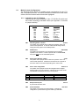
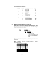
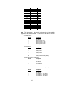
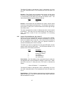
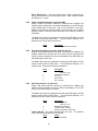
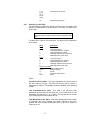
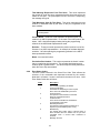
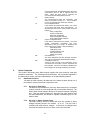
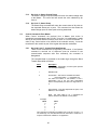
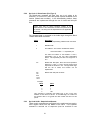
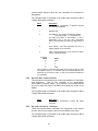
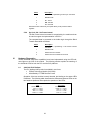
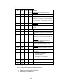
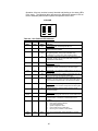
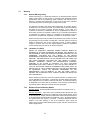
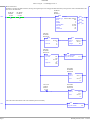
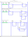
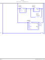
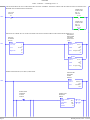
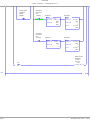
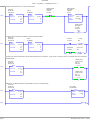
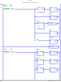
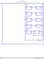
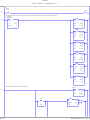
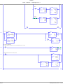
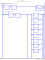
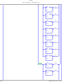
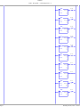
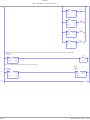
3100/3150 - HAR Harris RTU Slave Protocol Module Revision 1.0 USER MANUAL April 1996 ProSoft Technology, Inc. 1675 Chester Ave. Fourth Floor Bakersfield, CA 93301 [email protected] Please Read This Notice Successful application of the HAR card requires a reasonable working knowledge of the Allen-Bradley PLC or SLC hardware and the application in which the combination is to be used. For this reason, it is important that those responsible for implementing the HAR satisfy themselves that the combination will meet the needs of the application without exposing personnel or equipment to unsafe or inappropriate working conditions. This manual is provided to assist the user. Every attempt has been made to assure that the information provided is accurate and a true reflection of the product's installation requirements. In order to assure a complete understanding of the operation of the product, the user should read all applicable Allen-Bradley documentation on the operation of the A-B hardware. Under no conditions will ProSoft Technology, Inc. be responsible or liable for indirect or consequential damages resulting from the use or application of the HAR product. Reproduction of the contents of this manual, in whole or in part, without written permission from ProSoft Technology, Inc. is prohibited. Information in this manual is subject to change without notice and does not represent a commitment on the part of ProSoft Technology, Inc. Improvements and/or changes in this manual or the product may be made at any time. These changes will be made periodically to correct technical inaccuracies or typographical errors. ProSoft Technology, Inc. 1997 TABLE OF CONTENTS I. II III. IV V. VI VII Card Specifications.................................................................................................... 1 Configuring the HAR Module...................................................................................... 1 2.1 Hardware Overview ............................................................................................. 1 2.2 Module Jumper Configurations............................................................................. 2 2.2.1 3100/3101 for the 1771 Platform........................................................... 2 2.2.2 3150/3151 for the 1746 Platform........................................................... 3 2.3 Firmware Installation Procedure ( 3101 & 3151 ).................................................. 3 2.3.1 1771-DB Revision B Module................................................................. 3 2.3.2 1746-BAS Module................................................................................. 4 Harris Slave Card Functions ...................................................................................... 4 3.1 HARRIS Communications .................................................................................... 4 3.1.1 Command/Reply Cycle ......................................................................... 4 3.1.2 Command Types in the Harris Slave .................................................... 4 3.1.3 Command Error Checking .................................................................... 5 3.1.4 Data Integrity ........................................................................................ 5 3.2 Module Memory Layout........................................................................................ 5 3.2.1 Data Memory........................................................................................ 5 3.2.2 Communications Configuration Parameters.......................................... 6 HAR Theoretical Operation ........................................................................................ 6 4.1 Writing Data to the Module................................................................................... 6 4.1.1 Communications Configuration (Block ID Code 255) ............................ 7 4.1.2 Writing Port Register Data (Block ID Codes 0-27)................................. 11 4.2 Reading Data From the ProSoft Technology Module............................................ 13 4.2.1 Setpoint Arm/Operate - Op Codes 9/0AH ............................................. 13 4.2.2 Raise/Lower Command - Op Code 8 .................................................... 14 4.2.3 Control Point Arm/Operate - Op Codes 6/7........................................... 15 4.2.4 Power Fail Reset Command - Op Codes 0Bh ....................................... 16 4.2.5 Time Synchronization- Op Codes 11h&13h and 17h ............................. 16 4.2.6 Set Freeze Interval - Op Code 18h ....................................................... 16 4.2.7 Slave Error Code Table ........................................................................ 17 4.2.8 Error Status Codes ............................................................................... 18 Harris Commands ...................................................................................................... 19 5.1 Data Read Functions............................................................................................ 19 5.1.1 Op Code 0 : Data Dump ....................................................................... 19 5.1.2 Op Code 3 : Status Change Check ....................................................... 19 5.1.3 Op Code 4 : Status Change Dump........................................................ 20 5.1.4 Op Code 5 : Status Dump..................................................................... 20 5.2 Control Commands From Master ......................................................................... 20 5.2.1 Op Code 6 and 7 : Control Point Arm/Operate ...................................... 20 5.2.2 Op Code 8 : Raise/Lower (Port Type 3) ................................................ 21 5.2.3 Op Code 9/0Ah : Setpoint Arm/Operate................................................ 21 5.2.4 Op Code 0Bh : Power Fail Reset .......................................................... 22 5.2.5 Op Code 11h/13h/17h : Time Sync ....................................................... 22 5.2.6 Op Code 18h : Set Freeze Interval ....................................................... 23 Hardware Diagnostics ................................................................................................ 23 6.1 3100/3101 PLC Platform...................................................................................... 23 6.2 3150/3151 SLC Platform...................................................................................... 24 Support, Service and Warranty .................................................................................. 26 7.1 Technical Support ................................................................................................ 26 7.2 Module Service and Repair .................................................................................. 26 7.3 Warranty.............................................................................................................. 27 7.3.1 General Warranty Policy....................................................................... 27 7.3.2 Limitation of Liability............................................................................. 27 7.3.3 Hardware Product Warranty Details...................................................... 27 Appendices Appendix A PLC 5 Example Ladder Logic SLC Example Ladder Logic Appendix B Definitions of RS-232C Handshaking Signals RS-232 Cabling RS-422 and RS-485 cable I. Card Specifications The Harris Slave firmware upgrade gives Allen-Bradley 1771 and 1746 I/O compatible processors the ability to interface to a Harris M9000 Master device, or any device emulating this master function. The card includes the following capabilities: • • • • • • • • II Supported Op Codes: 0 : A/D and Accumulator Data Dump 3 : Status Check 4 : Status Change Dump 5 : Status Dump 6 : Trip/Close Control Arm 7 : Trip/Close Control Operate 8 : AGC Raise/Lower 9 : Set Point Control Arm 0A : Set Point Control Operate 0B : Power Fail Reset 0C : Port On-Line Status Scan 11 : Time Synchronization (SOE) 13 : Time Sync Adjust (SOE) 17 : Time Synchronization (Non SOE) 18 : Set Freeze Interval Supports broadcast commands from Master Software configuration (From PLC) Address : 1 to 63 (0 is broadcast) Parity : Odd Stop Bit : 1 Baud Rate : 300 TO 19,200 Hardware RS-232C handshaking for modem and radio applications RS-422/RS-485 compatible for multidrop applications Logical RTU addressing : Up to 4 slave addresses Register addressing Up to 7 ports, each port with one of following: Status : Up to 63 words Analog : Up to 63 words Accumulator 12 bit : Up to 63 words 24 bit : Up to 34 values 32 bit : Up to 12 values Response time The communication driver is written in assembly and in a compiled higher level language. As such, the interrupt capabilities of the hardware are fully utilized to minimize response delays to message requests from the master. Configuring the HAR Module 2.1 Hardware Overview When purchasing the module from ProSoft Technology, many of the jumper configurations will have been factory set. When purchasing the firmware from ProSoft Technology and the Allen-Bradley module from another source, particular attention must be paid to hardware configuration. 1 2.2 Module Jumper Configurations The following section details the available jumper configurations for the 1771 and 1746 platform solutions. As needed, differences between the module based solutions and the firmware based solutions are highlighted. 2.2.1 3100/3101 for the 1771 Platform Following are the jumper positions for the 1771-DB Rev B module and the ProSoft Technology 3100-HAR module (See Appendix C for details on jumper locations): Jumper 3100-HAR 3101-HAR JW1 JW2 JW3 JW4 JW5 JW6 JW7 JW8 JW9 N/A N/A N/A Not Used 8 Pt Not Used Enabled As Needed As Needed Enabled 32K PROM Turbo ASCII/ASCII 8 Pt Not Used Enabled As Needed As Needed JW1 Watchdog Enable / Disable Enable The position of this jumper does not affect the operation of the unit under normal operations. In order to enable the watchdog function, simply place the jumper in the Enabled position. JW2 PROM select 32K PROM The position of this jumper is very important to the successful operation of the module. In order to operate with our HAR EPROM, the jumper must be in the 32K PROM position. JW3 Speed select (Normal / Turbo) Turbo The position of this jumper does not affect the operation of the unit under normal operations. Unless there are reasons not to operate in the Turbo mode, we recommend operating in the Turbo mode. JW4 Port 1 and 2 configuration Position A The position of this jumper set must be changed from the shipped default position (D) to the A position. Operation of the module will be unpredictable if the jumper set is not in the A position. A B C D PRT 1 = ASCII PRT 1 = PGM PRT 1 = PGM PRT 1 = PGM DEFAULT PRT 2 = ASCII PRT 2 = ASCII PRT 2 = DF1 PRT 2 = ASCII DH485 = PGM DH485 = RUN DH485 = DISABLED DH485 = RUN JW5 Backplane 8/16 point 8 point mode should be used. JW6 Port 2 Baud Rate Not Used This jumper is not used by the HAR firmware. All baud rate configuration is performed through the ladder logic data table. 2 8 Point 2.2.2 JW7 Battery Enable / Disable Enabled This jumper should be placed in the Enabled position when the module is powered up. Although not critical to the operation of the module, this will back up some data registers in the module during a power failure or reset. JW8/9 RS Configuration for Port 1 and 2 See options on module The default from factory is RS-232, but all options are supported by the HAR firmware 3150/3151 for the 1746 Platform Following are the jumper positions for the 1746-BAS module and the ProSoft Technology 3150-HAR module (See Appendix C for details on jumper locations): Jumper 3150-HAR 3151-HAR JW1 JW2 JW3 JW4 As Needed As Needed N/A N/A As Needed As Needed 3-5, 4-6 1-3, 2-4 JW1/2 RS configuration for port 1 and 2 See Appendix C The default from factory is RS-232, but all options are supported by the HAR firmware JW3 Memory Selection 3-5, 4-6 When using the 3151 firmware solution with a 1746-BAS module, the EPROM is plugged into the User Socket. When in this configuration, it is essential that the jumper be in the correct position. With the 3150 module, this jumper will not affect operation of the product. JW4 Mode Configuration 1-3, 2-4 When using the 3151 firmware solution with a 1746-BAS module, it is essential that the jumper be in the correct position. With the 3150 module, this jumper will not affect operation of the product. 2.3 Firmware Installation Procedure ( 3101 & 3151 ) The following section details the available jumper configurations for the 1771 and 1746 platform solutions. As needed, differences between the module based solutions and the firmware based solutions are highlighted. 2.3.1 1771-DB Revision B Module The firmware installation steps are as follows: 1. Remove the card cover from the module 2. Plug the ProSoft Technology EPROM into the module's User Socket. Align the notches on the EPROM plastic carrier with the notches in the User socket. Make sure the EPROM is well seated 3. Replace the card cover 4. Turn the module over and locate the identification sticker in the unused indent. This 3 sticker will be important should the module ever require service. 2.3.2 1746-BAS Module The firmware installation steps are as follows: 1. Plug the ProSoft Technology EPROM into the module's User Socket. Align the notches on the EPROM plastic carrier with the notches in the User socket. Make sure the EPROM is well seated 2. Remove the plastic lens cover from the 1746BAS module and slip on the new cover provided with the firmware. Make sure the cover is firmly affixed to the module Once the firmware has been installed and the module’s jumpers have been verified, the hardware is ready to be inserted into the I/O rack. III. Harris Slave Card Functions 3.1 HARRIS Communications The ProSoft HARRIS module runs the slave version of the HARRIS protocol. This capability allows the module to communicate data from a PLC/SLC to a HARRIS Master (Such as the M9000 Series Master Station), and vice-versa. The module supports both point-to-point implementations as well as multi-drop implementations. The following discusses the functional capabilities of the ProSoft Harris Slave card. 3.1.1 Command/Reply Cycle Successful communications between a Harris Slave and a HARRIS Master will always consist of the following two transactions: Command: Message from master to slave. Reply: Response to command. A slave station will respond to a master issued command in several ways. Data Message: If the command was executed by the slave, the response message will include the data requested, or an acknowledgment that the command was executed. Error Message: If the command could not be executed by the slave, for whatever reason, the slave does not send any response. No Reply: If the master does not detect a reply within its timeout period (approx. 50 ms) , the master will re-transmit the command, before a time out error is issued. If the Slave could not decode the message or an error occurred preventing the Slave from recognizing the message, no response will be issued. 3.1.2 Command Types in the Harris Slave The Harris Slave can respond to two basic types of commands from the master; read data and write data. These are overviewed below, and discussed in detail in the Harris Protocol Specification. 4 Read Data: reads: The Harris Slave supports the following types of data OpCode 0 3 4 5 Bh Ch Write Data: writes: Description Data Dump Status Change Check Status Change Dump Status Dump Power Fail Reset Port On-Line Status Scan The Harris Slave supports the following types of data OpCode 6 7 8 9 Ah 11/17h 13h 18h Description Control Point Arm Control Point Operate Raise/Lower Setpoint Arm Setpoint Operate Time Sync Time Sync Adjust Set Freeze Interval 3.1.3 Command Error Checking When the Harris Slave cannot execute a command, an the module does not generate a response. The lack of a response generated at the slave will usually be indicative of an illegal function, an illegal address, bad data, or the inability to complete a transaction because of a network problem. 3.1.4 Data Integrity As in all good protocols, there must exist a level of data integrity checking to verify, with some degree of assurance, the quality of the transmitted data. The HARRIS protocol supports two types of error checking: • • Longitudinal Redundancy Check (LRC) One bit parity check (Odd only) LRC : When the master generates a message, a 8 bit LRC value is added to the end of the transmitted packet. The LRC value is a vertical parity check on the 6 data bit field of the message, generating an even vertical parity for the message. The receiving station executes the same calculation on the data and verifies the transmitted LRC. Any discrepancy will cause the message to be disregarded. Parity: Odd parity checking is added as an additional level of data security. 3.2 Module Memory Layout This section serves to explain the different segments of the memory which are utilized in the PLC and in the Harris Slave module. 3.2.1 Data Memory Data is transferred to the HARRIS module asynchronously from the Master's read requests. This allows the application ladder logic to manipulate and position the data as needed before transfer to the module. Since the HARRIS module stores the data from the ladder 5 logic in local memory, read requests from the Master are serviced immediately. The data registers are moved over the backplane between the card and the processor using the standard Block Transfer read and write functions, in the case of a PLC, and M0/M1 file transfers in the case of an SLC. The HARRIS module controls the data which is transferred from the module to the PLC/SLC during a read (BTR or M1 instruction) from the module. Being a slave module, the only time valid 'data' is transferred to the ladder logic is when a write command is issued from the Master. When writing data from the ladder logic to the module (BTW or M0 instruction), the ladder logic controls the data written to the HARRIS module. Appendix A contains a PLC5 and a SLC program showing an example of the logic to transfer data registers to and from the module. Section III discusses the transfer mechanism in detail, as well as several important relationships between PLC/SLC addressing and HARRIS addressing. 3.2.2 IV Communications Configuration Parameters The communications configuration parameter data block contains the information necessary for the module to set up the HARRIS communications port (peripheral port on the 1771-DB, and Port 1 on the 1746-BAS), as well as the Harris 'Port' configuration information necessary for the module to operate. On power up, the module will not proceed without receiving this configuration block. HAR Theoretical Operation Data transfers between the processor and the ProSoft Technology module occur using the Block Transfer commands, in the case of the PLC, and M0/M1 data transfer commands, in the case of the SLC. These commands transfer up to 64 physical registers per transfer. The logical data length changes depending on the data transfer function. The following discussion details the data structures used to transfer the different types of data between the ProSoft Technology module and the processor. The term 'Block Transfer' is used generically in the following discussion to depict the transfer of data blocks between the processor and the ProSoft Technology module. Although a true Block Transfer function does not exist in the SLC, we have implemented a pseudo-block transfer command in order to assure data integrity at the block level. Examples of the PLC and SLC ladder logic are included in Appendix A. In order for the ProSoft Technology module to function, the PLC must be in the RUN mode, or in the REM RUN mode. If in any other mode (Fault/PGM), the block transfers between the PLC and the module will stop, and communications will halt until block transfers resume. 4.1 Writing Data to the Module This section discusses how the transfer mechanism functions, and how to transfer data, command list and configuration data to the ProSoft module. 6 Data transfer to the module from the processor is executed through the Block Transfer Write function. The different types of data which are transferred require slightly different data block structures, but the basic data structure is: Word 0 1-63 Description Block ID code Data In a PLC, the BTW length must be configured for 64 words, otherwise module operation will be unpredictable. Where: Block ID Code: A block identifier code between 0 and 255 in value. This code is used by the ProSoft module to determine what to do with the data block. Valid codes are: Code 0-27 255 Description Harris Port Data Memory Module Communication Configuration Data: The data to be written to the module. The structure of the data is dependent on the Block ID code. The following sections provide details on the different structures. 4.1.1 Communications Configuration (Block ID Code 255) The ProSoft Technology firmware communication parameters must be configured at least once when the card is first powered up, and any time thereafter when the parameters must be changed. On power up, the module enters into a logical loop waiting to receive configuration data from the processor. While waiting, the module sets the first word of the BTR buffer to 255, telling the processor that the module must be configured before anything else will be done. The module will continuously perform block transfers until the communications configuration parameters block is received. Upon receipt, the module will begin execution of the command list if present, or begin looking for the command list from the processor. Transferring the Communications Configuration Parameters to the module will force a reset of the communication port, as well as dropping DTR for 200 ms pulses to reset any attached hardware. The configuration data block structure which must be transferred from the processor to the module is as follows: Data Word Description Block ID Header = 255 Port 1 0 1 2 3 4 N[]:0 N[]:1 N[]:2 N[]:3 N[]:4 7 Port Configuration Word Undefined Baud Rate RTS to TxD Delay RTS off Delay 5 6 N[]:5 N[]:6 Future Inter-character timing Port 2 10 N[]:10 Port Configuration Word 11 N[]:11 Undefined 12 N[]:12 Baud Rate 13 N[]:13 RTS to TxD Delay 14 N[]:14 RTS off Delay 15 N[]:15 Future 16 N[]:16 Inter-character timing System Configuration 20 N[]:20 Future 21 N[]:21 Future 22 N[]:22 Future 23 N[]:23 Future 24 N[]:24 Future 25 N[]:25 Number of Active Slaves 26 N[]:26 Harris RTU #1 Slave Address 27 N[]:27 Harris RTU #2 Slave Address 28 N[]:28 Harris RTU #3 Slave Address 29 N[]:29 Harris RTU #4 Slave Address 30 N[]:30 RTU #1 Port 0 Data Type 31 N[]:31 RTU #1 Port 1 Data Type 32 N[]:32 RTU #1 Port 2 Data Type 33 N[]:33 RTU #1 Port 3 Data Type 34 N[]:34 RTU #1 Port 4 Data Type 35 N[]:35 RTU #1 Port 5 Data Type 36 N[]:36 RTU #1 Port 6 Data Type 37 N[]:37 RTU #2 Port 0 Data Type 38 N[]:38 RTU #2 Port 1 Data Type 39 N[]:39 RTU #2 Port 2 Data Type 40 N[]:40 RTU #2 Port 3 Data Type 41 N[]:41 RTU #2 Port 4 Data Type 42 N[]:42 RTU #2 Port 5 Data Type 43 N[]:43 RTU #2 Port 6 Data Type 44 N[]:44 RTU #3 Port 0 Data Type 45 N[]:45 RTU #3 Port 1 Data Type 46 N[]:46 RTU #3 Port 2 Data Type 47 N[]:47 RTU #3 Port 3 Data Type 48 N[]:48 RTU #3 Port 4 Data Type 49 N[]:49 RTU #3 Port 5 Data Type 50 N[]:50 RTU #3 Port 6 Data Type 51 N[]:51 RTU #4 Port 0 Data Type 52 N[]:52 RTU #4 Port 1 Data Type 53 N[]:53 RTU #4 Port 2 Data Type 54 N[]:54 RTU #4 Port 3 Data Type 55 N[]:55 RTU #4 Port 4 Data Type 56 N[]:56 RTU #4 Port 5 Data Type 57 N[]:57 RTU #4 Port 6 Data Type Where: For Port 1 and Port 2 Port Configuration Word: This register contains several communication configuration parameters encoded into the word. These are as follows: Type: The operating mode of the port is selected by these bits: 8 Bits 3210 0001 0011 Harris Slave - 8 bit Harris Slave - 7 bit (should use this mode) Debug Mode: When configured in the debug mode, the other serial port on the module will transmit the data that has been received by the module. This is useful for determining communication problems: Bit 8 0 Disable Debug Mode 1 Enable Debug Mode Disable Receive LRC Calculation : When configured in the LRC Disable mode, the receive string is processed without the benefit of the LRC calculation. This has been provided because of problems encountered with several of the available test programs. This may be taken out in the future if not needed. Bit 9 0 Enable LRC Calculation 1 Disable LRC Calculation Stop Bits: The number of stop bits to be used is defined as follows: Bits 13 12 0 0 0 1 1 x One stop bit Two stop bits Invalid Port Configuration Parity: The parity mode to be used by the module is defined by this word as follows: Bits 15 14 0 0 0 1 1 0 1 1 No parity Odd parity Even parity Invalid Port Configuration Baud Rate: The baud rate at which the module is to operate. The baud rate is configured as follows: Value 0 1 2 3 4 5 6 7 Baud Rate 300 Baud 600 Baud 1200 Baud 2400 Baud 4800 Baud 9600 Baud 19200 Baud 38400 Baud 9 The module’s two ports are limited to an upper baud rate of either 19200 or 38400 baud. The module cannot be configured with one port at 19200 and the other at 38400. If an attempt is made to configure the module in this fashion, a Port Configuration Error will be returned. RTS To TXD Delay: This value represents the time in 1 ms increments to be inserted between asserting RTS, and the actual transmission of data. The delay, if greater in duration than the hardware time delay associated with CTS, will override the CTS line until the time-out is complete. This configurable parameter is useful when interfacing with modem based devices, or anytime line noise must be allowed to subside before data is transmitted. RTS Off Delay: The value in this word represents the number of 1 ms time delay increments inserted after the last character is transmitted and before RTS is dropped. The module automatically inserts a one character width Off Delay, assuring that RTS does not drop until after the last character has been completely sent. Unless working under unusual conditions, this value will normally be configured with a value of 0. The maximum value to be used is 65535 (0xffff). Inter-character Timing: This register is used in situations where the end of message character timeout delay must be extended beyond the normal 3.5 character widths. The value entered represents the number of 1 ms intervals of ‘no transmission’ which will be counted prior to accepting a message. This parameter will be useful in satellite or packet radio installation where a data transmission may be split between two packets. Increasing this value beyond the system’s packet handling time will eliminate timeout errors. System Configuration Number of Active Slaves: The module supports up to four valid slave addresses. This value allows the number of active slaves to be configured. Valid values range from 1 - 4. RTU #x Slave Address: The module supports up to four valid slave addresses. This allows a PLC to effectively increase its data handling capacity by a factor of four. Valid slave address are 1 to 63, with 0 reserved for broadcasts. RTU #x Port Data Type: These parameters are used to configure the module with the types of ports that the module is emulating. The Data Type word is broken down into a high byte and a low byte (it is easiest to setup these values in the hex display mode while in the A-B programming software) as follows: High Byte: Low Byte: Port Type Port Size Unused ports should be initialized to a value of 0 to insure that their is no invalid port configurations received by the module. 10 Valid configurations are as follows: Port Type 1 Port Size 1 2 1 2 Analog Port 16/32 Point 63 Point 513 514 1 Raise/Lower Port 6 Point R/L Port 769 1 2 3 Accumulator Port 63 12-bit Accumulators 31 24-bit Accumulators 31 32-bit Accumulators 1025 1026 1027 1 Set Point Port 16 setpoints 1537 2 3 4 6 4.1.2 Data Value Description Control and Indication(C&I) 32 Point C&I 63 Point C&I 257 258 Writing Port Register Data (Block ID Codes 0-27) Writing data to the ProSoft Technology module is a simple Block Transfer Write with Block ID codes from 0 to 27 followed by 63 words of data. The data that is to be made available to the master for reading is written into the module in this fashion. Word 0 1 Description BTW Block ID code Port Status BIT 0 1 2-63 DESCRIPTION Online(0) or Offline (1) Power Fail 0 = No power fail restart 1 = RTU has had a restart. This will remain set until a Power Fail Reset command is received (See Appendix A logic) Data Each separate Block ID represents an individual port in the Harris vernacular. Block ID Number: The Block ID codes correspond to the port addressing as follows: Block ID 0 1 2 3 4 5 6 7 8 RTU Slave # 1 1 1 1 1 1 1 2 2 11 Port 0 1 2 3 4 5 6 0 1 9 10 11 12 13 14 15 16 17 18 19 20 21 22 23 24 25 26 27 2 2 2 2 2 3 3 3 3 3 3 3 4 4 4 4 4 4 4 2 3 4 5 6 0 1 2 3 4 5 6 0 1 2 3 4 5 6 Data: The information to be moved to the module to be used for responses to the host commands. The structure of the data is a function of the port type selected: Indication Points Word 0 1 2 3 4 5 Description BTW Block ID Port Status Indicator points 1-16 Indicator points 17-32 Indicator points 33-48 Indicator points 49-63 Analog Points Word 0 1 2 3 4 63 Description BTW Block ID Port Status Analog Point 1 Analog Point 2 Analog Point 3 Analog Point 62 (max possible) Accumulator Points - 12 bit values Word Description 0 BTW Block ID 1 Port Status 2 Accumulator 1 3 Accumulator 2 4 Accumulator 3 63 Accumulator 62 (max possible) Accumulator Points - 24/32 bit values Word Description 0 BTW Block ID 1 Port Status 2 Accumulator 1 - Low Word 3 Accumulator 1 - High Word 4 Accumulator 2 - Low Word 12 5 62 63 4.2 Accumulator 2 - High Word Accumulator 31 - Low Word Accumulator 31 - High Word Reading Data From the ProSoft Technology Module This section discusses how to get data written to the ProSoft module by a Master into the PLC. The transfer of data from the ProSoft Technology module to the PLC is executed through the Block Transfer Read function. Four basic different types of data are read from the module into the PLC. The different types of data which are transferred require slightly different data block structures, but the basic data structure is: Word 0 1 2-62 Description Block ID Code BTW Block ID Number Data In a PLC, the BTR length must be configured for a length of 64 words, otherwise module operation will be unpredictable Where: Block ID Code: A block identifier code between 0 and 255 in value. This code is used by the ladder logic to determine what to do with the data block. Valid codes are: Code 0 128 129 130 131 132 255 Description Slave Port Error Status Setpoint Write Raise/Lower Command Control Point Command Power Fail Reset Time Sync Communication configuration BTW Block ID Number: The module returns this value to the processor to be used to enable the movement of register data and command list blocks to the module. The BTW Block ID number is developed by the module based on the parameters entered in parameter 25 of Block 255 (See Section 4.1.1). Data: The data corresponding to the command to be executed. The structure and content of this data block is dependent on the command to be executed. The following sections detail the command structures. 4.2.1 Setpoint Arm/Operate - Op Codes 9/0AH When a Setpoint Arm/Operate sequence is received from a Master, the ProSoft module transfers the command immediately to the BTR buffer for the ladder logic to work with. The Setpoint command will not be transferred to the buffer unless the Operate Command is received immediately after a Arm Command. 13 The ladder logic must be programmed to look at the BTR buffer, decode several words, and then take action. The BTR buffer definition, as it pertains to the Setpoint command is: Word 0 Description Setpoint write Block ID =128 BTW Block ID Number Port Address Point (Register) address Setpoint Value 1 2 3 4 Port Address : The Port Address value represents the port number for the addressed RTU which the Master is sending a control value. Within each RTU, there are 7 valid ports (0-6). This value is calculated as follows : = Slave ID Position * 7 + requested port The Slave ID Position is the between 0 and 3, representing one of the four valid configurable slaves. The requested port value can range from 0 to 6. Point (Register) Address: The Point Address represents the register address into which the Value field will be written. This value is used by the ladder logic to determine which word to act upon. Setpoint Value: The data value received from the Master. The values will be 12 bit value, and should be placed into an integer or BCD file. 4.2.2 Raise/Lower Command - Op Code 8 When a Raise/Lower Command is received from a Master, the ProSoft module transfers the command immediately to the BTR buffer for the ladder logic to work with. The ladder logic must be programmed to look at the BTR buffer, decode several words, and then take action. The BTR buffer definition, as it pertains to the Raise/Lower command is: Word 0 Description Raise/Lower Command Block ID = 129 BTW Block ID Number Port Address Direction - RL 1 Duration - RL 1 Direction - RL 2 Duration - RL 2 Direction - RL 6 Duration - RL 6 1 2 3 4 5 6 13 14 Port Address : The Port Address value represents the port number for the addressed RTU which the Master is sending a control value. Within each RTU, there are 7 valid ports (0-6). This value is calculated as follows : = Slave ID Position * 7 + requested port 14 The Slave ID Position is the between 0 and 3, representing one of the four valid configurable slaves. The requested port value can range from 0 to 6. Direction : Each Raise/Lower port address has 6 points, and the values for all six are transmitted at the same time. The direction of each point is communicated to the ladder logic through the direction value. The values that should be expected in these words are: Word 0 1 Description Raise Lower Duration : Each Raise/Lower port address has 6 points, and the values for all six are transmitted at the same time. The duration of the raise or lower period for each point is communicated to the ladder logic through the duration value. The value represents the number of milliseconds which a timer should be activated. This value may be moved directly into the preset for a timer. Note that a value of zero is the equivalent of a do-nothing command. 4.2.3 Control Point Arm/Operate - Op Codes 6/7 When a Control Point Arm/Operate sequence is received from a Master, the ProSoft module transfers the command immediately to the BTR buffer for the ladder logic to work with. The Control Point command will not be transferred to the buffer unless the Operate Command is received immediately after a Arm Command. The ladder logic must be programmed to look at the BTR buffer, decode several words, and then take action. The BTR buffer definition, as it pertains to the Control Point command is: Word 0 Description Control (Bit) command Block ID = 130 BTW Block ID Number Port Address Point (Bit) Address Set or Reset Value 1 2 3 4 Port Address : The Port Address value represents the port number for the addressed RTU which the Master is sending a control value. Within each RTU, there are 7 valid ports (0-6). This value is calculated as follows : = Slave ID Position * 7 + requested port The Slave ID Position is the between 0 and 3, representing one of the four valid configurable slaves. The requested port value can range from 0 to 6. Point Address: The Point Address represents the bit address which the Master is controlling. This value is used by the ladder logic to determine which bit address to act upon. 15 Set or Reset Value : The value in this field is used to determine the action to be taken on the Point Address location. Valid values are either a 0 (Reset) or a 1 (Set). 4.2.4 Power Fail Reset Command - Op Codes 0Bh When a Power Fail Reset command is received from a Master, the ProSoft module transfers the command immediately to the BTR buffer for the ladder logic to work with. Use for this command in the AllenBradley environment is relatively limited. As a minimum, the command should be used to reset the Power Fail Status bit to satisfy the needs of the Master. The ladder logic must be programmed to look at the BTR buffer, decode the Block ID, and then take action. The BTR buffer definition, as it pertains to the Control Point command is: Word 0 4.2.5 Description 131 : Power Fail Reset command Time Synchronization- Op Codes 11h&13h and 17h When a Time Synchronization command is received from a Master, the ProSoft module first converts the time value received into hh:mm:ss format and then transfers the values immediately to the BTR buffer for the ladder logic to work with. The ladder logic must be programmed to look at the BTR buffer, decode several words, and then take action. The BTR buffer definition, as it pertains to the Time Synchronization command is: Word 0 Description Time Sync Block ID = 132 BTW Block ID Number HH - hour MM - Minute SS - Seconds 1 2 3 4 4.2.6 Set Freeze Interval - Op Code 18h When a Set Freeze Interval command is received from a Master, the ProSoft module transfers the value received immediately to the BTR buffer for the ladder logic to work with. The ladder logic must be programmed to look at the BTR buffer, decode several words, and then take action. The BTR buffer definition, as it pertains to the Set Freeze Interval command is: Word 0 Description Set Freeze Interval Block ID = 133 BTW Block ID Number Freeze Interval - Minutes Minutes converted into Seconds 1 2 3 Freeze Interval: The value received from the host. values and associated actions are as follows: Value 0 Action Freeze immediate 16 The possible 4.2.7 1,2,3, 4,5,6, 10,12, 15,20, 30,60 Valid intervals in minutes 63 Stop Freeze processing Slave Error Code Table The HAR Module monitors the status of all Slave port commands. This status is communicated to the processor in the form of a Slave Error Code Table. The Slave Error Code Table is initialized to zero on power up, and every time the module receives the 255 configuration data block. The Slave Error Table is a 20 word block. The structure of the data block is as follows: Word Description Port 1 0 Current port status 1 Last transmitted error condition 2 Total Messages to this slave 3 Total Msg responses from this slave 4 Total Msgs seen by this slave Port 2 5 Current port status 6 Last transmitted error condition 7 Total Messages to this slave 8 Total Msg responses from this slave 9 Total Msgs seen by this slave System Information 10-11 Product Name (ASCII) 12-13 Revision (ASCII) 14 (blank) 15 Production Run Number 16-19 Spare Where: Current Port Error Status: This value represents the current value of the error code for the port. This value will only be valid if the port is configured as a Slave. The possible values are detailed in the following section. Last Transmitted Error Code: This value is the last error code transmitted to the master by this slave port. Error codes which can be expected in this field are 0, 1, 2, 3, and 6. The field will only be cleared by re configuring the module (Block ID 255). Total Messages to This Slave: This value represents the total number of messages that have matched this slaves address on this port, whether the slave actually determined them to be good (worthy of response) or not. 17 Total Message Responses From This Slave: This value represents the number of good (non-error) responses that the slave has sent to the master on this port. The presumption is that if the slave is responding, the message was good. Total Messages Seen By This Slave: This value represents the total number of commands seen by the slave on this port, regardless of the slave address. All counters in the Slave Error Table will rollover to 0 after reaching 65535 Product Name: These two words represent the product name of the module in an ASCII representation. In the case of the HAR product, the letters ‘ HAR ‘ should be displayed when placing the programming software in the ASCII data representation mode. Revision : These two words represent the product revision level of the firmware in an ASCII representation. An example of the data displayed would be ‘1.40’ when placing the programming software in the ASCII data representation mode. Blank: Not used at this time Production Run Number: This number represents the ‘batch’ number that your particular chip belongs to. This number should appear as a number equal or greater than 2. This should help the factory determine when the User’s chip was created. 4.2.8 Error Status Codes The Error Codes returned in the Slave Error Code Table reflects the outcome of the commands and responses executed by the module. Note that in all cases, if a zero is returned, there was not an error. Valid Error Status Codes are as follows: Code 0 1 2 3 4 6 8 Description All OK The module is operating as desired. Control Invalid Point The Master is attempting to control a point which cannot be addressed by the slave Control Timeout The Operate command was not received within the required time frame Invalid Function The Function received from the Master is not supported by the slave Data Sequence Error The Operate command was received out of sequence (not immediately after a Arm) Module Busy The module busy status code is returned when a write command from the master has not yet been completed when a second write command is received Message Time-out 18 10 16 18 254 255 V. Communications with the addressed slave have been unsuccessful due to a lack of response from the slave. When this Error Code is received, the command has been attempted three times. Buffer Overflow The communications buffer has overflowed and reset the character counter to 0. If this condition occurs, the message size needs to be checked. Port Configuration Error If this value is returned from the module, one or both of the serial ports have been misconfigured. To determine the exact source of the problem, verify the following: Parity configuration Stop bit configuration Baud rate configuration Start Input Register Address Start Output Register Address System Configuration Error If this value is returned from the module, one of the system configuration parameters has been determined to be out of range. To determine the exact source of the problem, verify the following: Read Block Count Write Block Count Command Block Count Slave Error Pointer Master Error Pointer Checksum Error The slave determined that the message checksum was in error, and therefore discarded the message TX Hardware Time-out A time-out has occurred in the transmission of the command from the master, and the command has been aborted. This error is usually an indication that the CTS signal is not being received by the module. Harris Commands The ProSoft Technology Harris Slave module supports the most commonly used data read/write commands. The following sections discusses the commands supported in the Harris Slave module, and their implementation in the Allen-Bradley platform. 5.1 Data Read Functions As stated in earlier sections, the data sent to the master is taken directly out of the module's memory at the time a response is sent. 5.1.1 Op Code 0 : Data Dump The Data Dump command will return the data values for the requested number of points on each configured A/D or Accumulator data port. The Harris Slave module supports access to 62 words of data per configured port. With the module supporting 7 data ports per slave address, and four slave addresses, the module is capable of transferring up to 1736 words of data. 5.1.2 Op Code 3 : Status Change Check The Status Change Check command will return the number of status changes currently stored in the module, up to 31. The Op Code 4 command will retrieve these changes. If more than 31 changes have occurred, the module will return a value of 63 in the count field. 19 5.2 5.1.3 Op Code 4 : Status Change Dump The Status Change Dump command will return the status change data to the Master. The count field will contain the value obtained by Op Code 3. 5.1.4 Op Code 5 : Status Dump The Status Dump command will return the current status of all points on the requested Status port or ports. This command can also clears the status change queue on those ports returning status data. Control Commands From Master When Control commands are received from a Master, their action is immediately communicated to the PLC/SLC for action. No modification is made directly to the ProSoft Module's memory as a result of a Control Command. In order for any Control action to be reflected in the module's memory, it must be transferred to the module as part of the regular data transfer mechanism. 5.2.1 Op Code 6 and 7 : Control Point Arm/Operate These control commands are recognized by the module. If the Operate command is received out of sequence (must be received in next communication sequence after Arm command), the command is disregarded. The command data is presented to the ladder logic through the Block Transfer Read buffer as follows: Word 0 Description Value of 130, representing a Control point Operate command (Bit Set/Reset). 1 BTW Block ID 2 Port Number : This value is calculated as follows : = Slave ID Position * 7 + requested port The Slave ID Position is the between 0 and 3, representing one of the four valid configurable slaves. The requested port value can range from 0 to 6. 3 Point Number : This value represents the point, or bit address, to be controlled. 4 State : This value, either a 0 or 1, represents the state to which the bit address is to be placed. Example: Word Value 0 130 1 1 2 3 3 2 4 1 This command is instructing the ladder logic to set bit 2 of Port 3. In our ladder logic, we could decode this as an instruction to set B13/2, or map the command as needed for our application. 20 5.2.2 Op Code 8 : Raise/Lower (Port Type 3) The Raise/Lower command will allow from one to six points to be controlled. In a Harris RTU, there are special modules dedicated to this function (Raise/Lower modules). In the Allen-Bradley platform, these commands are implemented through the use of timers and binary/IO files. Please note that no timing functions related to the implementation of the raise/lower command are performed by the module. All timing must be implemented in the application ladder logic. The command data is presented to the ladder logic through the Block Transfer Read buffer as follows: Word 0 Description Value of 129, representing a Raise/Lower command. 1 BTW Block ID 2 Port Address : This value is calculated as follows : = Slave ID Position * 7 + requested port The Slave ID Position is the between 0 and 3, representing one of the four valid configurable slaves. The requested port value can range from 0 to 6. 3/4 Raise/Lower data pairs, where first word represents direction( 0 = raise, 1 = lower), and the second word represents the duration in ms. Through ladder logic and the use of timers, this function can be implemented. 5/6 7/8 9/10 11/12 13/14 Raise/Lower data pairs as above Example: Word Value 0 129 1 2 2 3 3 1 4 100 This command is instructing the ladder logic to turn on the Port Address 3 Lower timer for 100 ms. In our ladder logic, we could move the duration value to a T[].PRE and then enable the timer for this period. 5.2.3 Op Code 9/0Ah : Setpoint Arm/Operate These control commands are recognized by the module and are used to move register values from the Master to the slave. If the Operate command is received out of sequence (must be received in next 21 communication sequence after the Arm command), the command is disregarded. The command data is presented to the ladder logic through the Block Transfer Read buffer as follows: Word 0 Description Value of 128, representing a Setpoint Operate command (Bit Set/Reset). 1 BTW Block ID 2 Port Address : This value is calculated as follows : = Slave ID Position * 7 + requested port The Slave ID Position is the between 0 and 3, representing one of the four valid configurable slaves. The requested port value can range from 0 to 6. 3 Point Address : This value represents the point, or register address, to be controlled. 4 Value : This represents the 12 bit value to be written into the addressed register. Example: Word Value 0 128 1 3 2 3 3 0 4 1234 This command is instructing the ladder logic to write a value of 1234 into register 0 of port 3. In our ladder logic, we could decode this as an instruction to set word 0 of a file, or map the command as needed for our application. 5.2.4 Op Code 0Bh : Power Fail Reset This command is recognized by the module and passed on to the ladder logic application. Use for this command in the Allen-Bradley environment is relatively limited. As a minimum, the command should be used to reset the Power Fail Status bit to satisfy the needs of the Master. The command data is presented to the ladder logic through the Block Transfer Read buffer as follows: Word 0 5.2.5 Description Value of 131, representing a Power Fail Reset command. Op Code 11h/13h/17h : Time Sync These time synchronization commands are recognized by the module and are used to move register values from the Master to the slave. The command data is presented to the ladder logic through the Block Transfer Read buffer as follows: 22 Word 0 Description Value of 132, representing a Time Sync command 1 BTW Block ID 2 3 4 HH - Hours MM - Minutes SS - Seconds Note that the time values may be copied directly to the processor status registers. 5.2.6 Op Code 18h : Set Freeze Interval The Set Freeze Interval command is recognized by the module and can be used to support the implementation in the PLC The command data is presented to the ladder logic through the Block Transfer Read buffer as follows: Word 0 VI 1 Description Value of 133, representing a Set Freeze Interval command BTW Block ID 2 3 Freeze Interval in minutes Freeze Interval converted into seconds Hardware Diagnostics Several hardware diagnostics capabilities have been implemented using the LED indicator lights on the front of the module. The following sections explain the meaning of the individual LEDs for both the PLC and the SLC platforms. 6.1 3100/3101 PLC Platform The PLC platform HAR product is available in two forms: • ProSoft Technology Module (3100-CIM) • Allen-Bradley 1771-DB Revision B card Operation of the two modules is nearly identical, but labeling on the status LEDs is different. The following table documents the differences between LEDs on the two hardware platforms and explains the operation of the LEDs. ProSoft CIM Card ACTIVE ¡ ¡ FLT CFG ¡ ¡ BPLN ERR1 ¡ ¡ ERR2 TXD1 ¡ ¡ TXD2 RXD2 ¡ ¡ RXD2 A-B 1771-DB Rev B Card ACTIVE ¡ ¡ FLT DH485 ¡ ¡ BTLO LED1 ¡ ¡ LED2 PT1X ¡ ¡ PT2X PT1R ¡ ¡ PT2R 23 Table 6.1 : PLC Platform LED Indication ProSoft CIM ACT A-B DB/B ACT Color Green Status Blink (Fast) On Blink ( 1/Sec) Off FLT FLT Red Off On CFG DH485 Green Off Blink On BPLN BTLO Red Off On ERR1 ERR2 LED1 LED2 Amber Off Blink On 6.2 Indication Normal state : The module is operating normally and successfully Block Transferring with the PLC The module is receiving power from the backplane, but there may be some other problem Indicates the module has somehow entered the Basic Programming Mode. Verify jumper JW4 (DB/B only) configuration. If all are correct, then contact the factory The module is attempting to Block Transfer with the PLC and has failed. The PLC may be in the PGM mode or may be faulted Normal State : No system problems are detected during background diagnostics A system problem was detected during background diagnostics. Please contact factory for technical support Normal state : No configuration related activity is occurring at this time This light blinks every time a Module Configuration block (ID = 255) is received from the processor ladder logic The light is on continuously whenever a configuration error is detected. The error could be in the Port Configuration data or in the System Configuration data. See Section 4 for details Normal State : When this light is off and the ACT light is blinking quickly, the module is actively Block Transferring data with the PLC Indicates that Block Transfers between the PLC and the module have failed.( Not activated in the initial release of the product) Normal State : When the error LED is off and the related port is actively transferring data, there are no communication errors Periodic communication errors are occurring during data communications. See Section 4 to determine the error condition This LED will stay on under several conditions: • CTS input is not being satisfied • Port Configuration Error • System Configuration Error • Unsuccessful comm on HAR slave • Recurring error condition on HAR master Tx1 Tx2 PT1X PT2X Green Blink The port is transmitting data. Rx1 Rx2 PT1R PT2R Green Blink The port is receiving data 3150/3151 SLC Platform The PLC platform HAR product is available in two forms: • • ProSoft Technology Module (3150-CIM) Allen-Bradley 1746-BAS card 24 Operation of the two modules is nearly identical and labeling on the status LEDs is the same. The following table documents the differences between LEDs on the two hardware platforms and explains the operation of the LEDs. 3150-HAR COMMUNICATIONS ACT FAULT CFG BPLN PRT1 ERR1 PRT2 ERR2 Table 6.2 : SLC Platform LED Indication LED Name ACT Color Green Status Blink (Fast) On Blink ( 1/Sec) Off FLT Red Off On CFG Green Off Blink On BPLN Red Off On ERR1 ERR2 Amber Off Blink On TxRx1 TxRx2 Green Blink Indication Normal state : The module is operating normally and successfully Block Transferring with the SLC The module is receiving power from the backplane, but there may be some other problem Indicates the module has somehow entered the Basic Programming Mode. Verify jumper JW3 (BAS only) configuration. If all are correct, then contact the factory The module is attempting to Block Transfer with the SLC and has failed. The SLC may be in the PGM mode or may be faulted (Not in initial release) Normal State : No system problems are detected during background diagnostics A system problem was detected during background diagnostics. Please contact factory for technical support Normal state : No configuration related activity is occurring at this time This light blinks every time a Module Configuration block (ID = 255) is received from the processor ladder logic The light is on continuously whenever a configuration error is detected. The error could be in the Port Configuration data or in the System Configuration data. See Section 4 for details Normal State : When this light is off and the ACT light is blinking quickly, the module is actively Block Transferring data with the SLC Indicates that Block Transfers between the SLC and the module have failed Normal State : When the error LED is off and the related port is actively transferring data, there are no communication errors Periodic communication errors are occurring during data communications. See Section 4 to determine the error condition This LED will stay on under several conditions: • CTS input is not being satisfied • Port Configuration Error • System Configuration Error • Unsuccessful comm on HAR slave • Recurring error condition on HAR master The port is communicating, either transmitting or receiving data 25 VII Support, Service and Warranty 7.1 Technical Support ProSoft Technology survives on its ability to provide meaningful support to its customers. Should any questions or problems arise, please feel free to contact us at: Factory/Technical Support Corporate ProSoft Technology, Inc. 9801 Camino Media, Suite 105 Bakersfield, CA 93311 (661) 664-7208 (800) 326-7066 (661) 664-7233 (fax) E-mail address: [email protected] Before calling for support, please prepare yourself for the call. In order to provide the best and quickest support possible, we will most likely ask for the following information (you may wish to fax it to us prior to calling): 1. Product Serial and Version Number 2. Configuration Information - Communication Configuration - Master Command List - Jumper positions 3. System hierarchy 4. Physical connection information - RS-232, 422 or 485 - Cable configuration 5. Module Operation - Block Transfers operation - LED patterns An after-hours answering system (on the Bakersfield number) allows pager access to one of our qualified technical and/or application support engineers at any time to answer the questions that are important to you. 7.2 Module Service and Repair The HAR card is an electronic product, designed and manufactured to function under somewhat adverse conditions. As with any product, through age, misapplication, or any one of many possible problems, the card may require repair. When purchased from ProSoft Technology, the module has a one year parts and labor warranty according to the limits specified in the warranty. Replacement and/or returns should be directed to the distributor from whom the product was purchased. If you need to return the card for repair, it is first necessary to obtain an RMA number from ProSoft Technology. Please call the factory for this number and display the number prominently on the outside of the shipping carton used to return the card. 26 7.3 Warranty 7.3.1 General Warranty Policy ProSoft Technology, Inc. (Hereinafter referred to as ProSoft) warrants that the Product shall conform to and perform in accordance with published technical specifications and the accompanying written materials, and shall be free of defects in materials and workmanship, for the period of time herein indicated, such warranty period commencing upon receipt of the Product. This warranty is limited to the repair and/or replacement, at ProSoft's election, of defective or non-conforming Product, and ProSoft shall not be responsible for the failure of the Product to perform specified functions, or any other nonconformance caused by or attributable to: (a) any misapplication of misuse of the Product; (b) failure of Customer to adhere to any of ProSoft's specifications or instructions; (c) neglect of, abuse of, or accident to, the Product; or (d) any associated or complementary equipment or software not furnished by ProSoft. Limited warranty service may be obtained by delivering the Product to ProSoft and providing proof of purchase or receipt date. Customer agrees to insure the Product or assume the risk of loss or damage in transit, to prepay shipping charges to ProSoft, and to use the original shipping container or equivalent. Contact ProSoft Customer Service for further information. 7.3.2 Limitation of Liability EXCEPT AS EXPRESSLY PROVIDED HEREIN, PROSOFT MAKES NO WARRANT OF ANY KIND, EXPRESSED OR IMPLIED, WITH RESPECT TO ANY EQUIPMENT, PARTS OR SERVICES PROVIDED PURSUANT TO THIS AGREEMENT, INCLUDING BUT NOT LIMITED TO THE IMPLIED WARRANTIES OF MERCHANT ABILITY AND FITNESS FOR A PARTICULAR PURPOSE. NEITHER PROSOFT OR ITS DEALER SHALL BE LIABLE FOR ANY OTHER DAMAGES, INCLUDING BUT NOT LIMITED TO DIRECT, INDIRECT, INCIDENTAL, SPECIAL OR CONSEQUENTIAL DAMAGES, WHETHER IN AN ACTION IN CONTRACT OR TORT (INCLUDING NEGLIGENCE AND STRICT LIABILITY), SUCH AS, BUT NOT LIMITED TO, LOSS OF ANTICIPATED PROFITS OR BENEFITS RESULTING FROM, OR ARISING OUT OF, OR IN CONNECTION WITH THE USE OR FURNISHING OF EQUIPMENT, PARTS OR SERVICES HEREUNDER OR THE PERFORMANCE, USE OR INABILITY TO USE THE SAME, EVEN IF PROSOFT OR ITS DEALER'S TOTAL LIABILITY EXCEED THE PRICE PAID FOR THE PRODUCT. Where directed by State Law, some of the above exclusions or limitations may not be applicable in some states. This warranty provides specific legal rights; other rights that vary from state to state may also exist. This warranty shall not be applicable to the extent that any provisions of this warranty is prohibited by any Federal, State or Municipal Law that cannot be preempted. 7.3.3 Hardware Product Warranty Details Warranty Period : ProSoft warranties hardware product for a period of one (1) year. Warranty Procedure : Upon return of the hardware Product ProSoft will, at its option, repair or replace Product at no additional charge, freight prepaid, except as set forth below. Repair parts and replacement Product will be furnished on an exchange basis and will be either reconditioned or new. All replaced Product and parts become the property of ProSoft. If ProSoft determines that the Product is not under warranty, it will, at the Customer's option, repair the Product using current ProSoft standard rates for parts and labor, and return the Product freight collect. 27 Appendix A Example Ladder Logic PLC-5 SLC-5/03 Provides a working example of the ladder logic needed to implement a solution B Port Connection Diagrams Appendix A Example PLC 5 Ladder Logic Example SLC Ladder Logic HAR5.RSP LAD 3 - btw_btr --- Total Rungs in File = 6 0000 Block Transfer Read In addition to executing the BTR instruction, this rung also begins the process of setting up the BTW Block ID by moving the 2nd value in the BTR buffer to the first value in the BTW buffer BT READ BT READ BT WRITE FROM ENABLE ENABLE MODULE N7:400 N7:300 BTR EN Block Transfer Read 15 15 Module Type Generic Block Transfer DN Rack 000 Group 2 ER Module 0 Control Block N7:400 Data File N7:410 Length 64 Continuous No DECODE BT READ BLOCK ID EQU Equal Source A Source B DECODE BT READ BLOCK ID LIM Limit Test Low Lim Test High Lim N7:410 0< 0 0< 128 128< N7:410 0< 132 132< COP Copy File Source Dest Length JSR Jump To Subroutine Prog File Number ENCODES BT WRITE BLOCK ID MOV Move Source Dest 1ST SCAN CONFIG DETECT N7:309 0 #N7:412 #N7:70 20 ENCODES BT WRITE BLOCK ID MOV Move Source Dest U:5 N7:411 3< N7:310 0< 255 255< N7:310 0< Call to the routine which handles some of the command specific functionality 0001 Page 1 JSR Jump To Subroutine Prog File Number U:4 Monday, June 28, 1999 - 14:10:14 HAR5.RSP LAD 3 - btw_btr --- Total Rungs in File = 6 0002 0003 Build file pointer depending on the port number being processed. In this example, 0-6 are for file 10 and 7-13 are for file 11 DECODE BT READ BT WRITE BT WRITE ENABLE ENABLE BLOCK N7:400 N7:300 LIM Limit Test 15 15 Low Lim 0 0< Test N7:310 0< High Lim 6 6< FILE POINTER MOV Move Source Dest 10 10< N7:307 10< BT WRITE DATA AND CONFIGURATION ENCODING The BTW Data Block is incremented prior to each BTW command being executed in rung 2. If the card configuration is activated (first scan or N7:410=255), then 255 is written into the BTW Block ID. DECODE BT READ BT WRITE BT WRITE FILE ENABLE ENABLE BLOCK POINTER N7:400 N7:300 LIM MOV Limit Test Move 15 15 Low Lim 7 Source 11 7< 11< Test N7:310 Dest N7:307 0< 10< High Lim 13 13< ADJUST PORT NUM SUB Subtract Source A N7:310 0< Source B 7 7< Dest N7:310 0< Move data from data table into the module. BT READ ENABLE N7:400 BT WRITE ENABLE N7:300 15 15 0004 DECODE BT WRITE BLOCK LIM Limit Test Low Lim Test High Lim 0 0< N7:310 0< 7 7< HARRIS RTU/PORT POINTER MUL Multiply Source A Source B Dest N7:310 0< 50 50< N7:308 300< WRITE TO BT WRITE BUFFER COP Copy File Source #N[N7:307]:[N7:308] Dest #N7:311 Length 50 Page 2 Monday, June 28, 1999 - 14:10:16 HAR5.RSP LAD 3 - btw_btr --- Total Rungs in File = 6 DECODE BT WRITE BLOCK EQU Equal Source A Source B N7:310 0< 255 255< WRITE TO BT WRITE BUFFER COP Copy File Source Dest Length #N7:0 #N7:311 63 1ST SCAN CONFIG DEACTIVATE N7:309 U 0 BT WRITE TO MODULE BTW Block Transfer Write Module Type Generic Block Transfer Rack 000 Group 2 Module 0 Control Block N7:300 Data File N7:310 Length 64 Continuous No 0005 Page 3 EN DN ER END Monday, June 28, 1999 - 14:10:16 HAR5.RSP LAD 4 - continuous --- Total Rungs in File = 4 0000 LATCH THE POWER FAIL STATUS BITS FOR THE ACTIVE RTU NUMBERS. THIS RUNG TAKES CARE OF FIRST BIT AND FOLLOWING RUNG DISTRIBUTES TO OTHER PORTS FOR THE RTU POWER FAIL STATUS FOR 1ST SCAN RTU #0 STATUS PORT #0 S:1 N10:0 L 15 1 POWER FAIL STATUS FOR RTU #1 PORT #0 N11:0 L 1 0001 THIS LOGIC IS A MIMIC OF RTU #0 PORT #0 POWER FAIL DATA FOR THE OTHER 6 PORTS ASSOCIATED WITH RTU #0. SET/RESET THE POWER DECODE FAIL BITS BT WRITE FOR PORTS BLOCK #1-#6 LIM MVM Limit Test Masked Move Low Lim 1 Source N10:0 1< 2< Test N7:310 Mask 02H 0< 2< High Lim 6 Dest N10:[N7:308] 6< 2< MVM Masked Move Source N11:0 3< Mask 02H 2< Dest N11:[N7:308] 2< RAISE/LOWER SETPOINT (OP CODE 8) OPERATION RAISE/LOWR SETPOINT TIMER PRESET MOV Move Source 0002 Dest RAISE/LOWR SETPOINT ACTIVE STATUS B3:0 7 Page 4 RAISE/LOWR SETPOINT TIMER TON Timer On Delay Timer Time Base Preset Accum N10:801 150< T4:0.PRE 150< EN T4:0 0.01 150< 0< DN Monday, June 28, 1999 - 14:10:18 HAR5.RSP LAD 4 - continuous --- Total Rungs in File = 4 RAISE/LOWR SETPOINT TIMER TIMING T4:0 SETPOINT UP/DOWN BIT 1=DOWN N10:800 TT 0 SETPOINT LES Less Than (A<B) Source A N11:825 3468< Source B 4095 4095< SETPOINT ADD Add Source A Source B Dest SETPOINT UP/DOWN BIT 1=DOWN N10:800 0 SETPOINT GRT Greater Than (A>B) Source A N11:825 3468< Source B 0 0< SETPOINT SUB Subtract Source A Source B Dest T4:0 DN 0003 Page 5 N11:825 3468< 1 1< N11:825 3468< N11:825 3468< 1 1< N11:825 3468< RAISE/LOWR SETPOINT ACTIVE STATUS B3:0 U 7 END Monday, June 28, 1999 - 14:10:23 HAR5.RSP LAD 5 - btr_handle --- Total Rungs in File = 5 RAISE/LOWER SETPOINT (OP CODE 8) DECODING 0000 DECODE BT READ BLOCK ID EQU Equal Source A Source B N7:410 0< 129 129< PORT NUMBER EQU Equal Source A Source B RAISE/LOWR SETPOINT ACTIVE STATUS B3:0 N7:412 0< 3 3< 7 RAISE/LOWR SETPOINT CONFIG DATA COP Copy File Source #N7:413 Dest #N10:800 Length 12 RAISE/LOWR SETPOINT ACTIVE STATUS B3:0 L 7 0001 CONTROL POINT OPERATE COMMAND SETS AND RESETS BITS DECODE BT READ PORT BLOCK ID NUMBER EQU EQU Equal Equal Source A N7:410 Source A N7:412 0< 0< Source B 130 Source B 0 130< 0< SET BIT ACTIVE N7:414 0 RESET BIT ACTIVE N7:414 0 0002 0003 0004 Page 6 LATCH BIT B13 L [N7:413] UNLATCH BIT B13 U [N7:413] POWER FAIL RESET COMMAND CLEARS THE POWER FAIL STATUS BITS. LOGIC IN FILE 4 TAKES CARE OF CLEARING THE STATUS BITS IN OTHER PORTS POWER FAIL DECODE STATUS FOR BT READ RTU #0 BLOCK ID PORT #0 EQU N10:0 U Equal Source A N7:410 1 0< Source B 131 POWER FAIL 131< STATUS FOR RTU #1 PORT #0 N11:0 U 1 TIME SYNC COMMAND MOVES NEW HH:MM:SS VALUES TO PROCESSOR DECODE BT READ BLOCK ID EQU Equal Source A N7:410 0< Source B 132 132< PLC TIME REGISTERS COP Copy File Source Dest Length #N7:413 #S:21 3 END Monday, June 28, 1999 - 14:10:25 HAR503 LAD 3 - M0_M1 --- Total Rungs in File = 4 BT WRITE "Blcok Transfer" Write to module WRITE WRITE ENABLE DONE I:1 O:1 EQU Equal Source A 0000 0 1746-BAS-5/02 0 1746-BAS-5/02 Source B BT READ BLOCK ID LIM Limit Test Low Lim Test High Lim M1:1.0 ?< 0 0< N7:150 0< N7:150 0< 132 132< COP Copy File Source Dest Length #M1:1.2 #N7:70 20 BT READ BLOCK ID COP Copy File Source Dest Length #M1:1.0 #N7:150 64 JSR Jump To Subroutine SBR File Number BT WRITE TO MODULE MOV Move Source Dest BT WRITE TO MODULE MOV Move Source B3:0 0 Dest M1:1.1 ?< M0:1.0 ?< 255 255< M0:1.0 ?< JSR Jump To Subroutine SBR File Number 0001 WRITE ENABLE I:1 WRITE DONE O:1 0 1746-BAS-5/02 0 1746-BAS-5/02 0002 BT WRITE TO MODULE EQU Equal Source A Source B BT WRITE TO MODULE EQU Equal Source A Source B BT WRITE TO MODULE EQU Equal Source A Source B Page 1 U:5 M0:1.0 ?< 0 0< M0:1.0 ?< 1 1< M0:1.0 ?< 2 2< COP Copy File Source Dest Length #N10:0 #M0:1.1 50 COP Copy File Source Dest Length #N10:50 #M0:1.1 50 U:4 COP Copy File Source #N10:100 Dest #M0:1.1 Length 50 Monday, June 28, 1999 - 14:13:18 HAR503 LAD 3 - M0_M1 --- Total Rungs in File = 4 BT WRITE TO MODULE EQU Equal Source A Source B BT WRITE TO MODULE EQU Equal Source A Source B BT WRITE TO MODULE EQU Equal Source A Source B BT WRITE TO MODULE EQU Equal Source A Source B BT WRITE TO MODULE EQU Equal Source A Source B M0:1.0 ?< 3 3< M0:1.0 ?< 4 4< M0:1.0 ?< 5 5< M0:1.0 ?< 6 6< M0:1.0 ?< 255 255< COP Copy File Source #N10:150 Dest #M0:1.1 Length 50 COP Copy File Source #N10:200 Dest #M0:1.1 Length 50 COP Copy File Source Dest Length #N11:0 #M0:1.1 50 COP Copy File Source Dest Length #N11:50 #M0:1.1 50 COP Copy File Source Dest Length #N7:0 #M0:1.1 57 B3:0 U 0 WRITE DONE O:1 0 1746-BAS-5/02 0003 Page 2 END Monday, June 28, 1999 - 14:13:21 HAR503 LAD 4 - continuous --- Total Rungs in File = 7 0000 0001 LATCH THE POWER FAIL STATUS BITS FOR THE ACTIVE RTU NUMBERS. THIS RUNG TAKES CARE OF THE FIRST BIT AND FOLLOWING RUNG DISTRUBUTE TO OTHER PORTS FOR THE RTU FIRST SCAN S2:1 N10:0 L 15 1 THIS LOGIC IS A MIMIC OF RTU #0 PROT #0 POWER FAIL DATA FOR THE OTHER 6 PORTS ASSOCIATED WITH RTU #0 BT WRITE TO MODULE LIM Limit Test Low Lim 1 1< Test M0:1.0 ?< High Lim 6 6< MVM Masked Move Source N10:0 0< Mask 0002h 2< Dest N10:50 0< MVM Masked Move Source N10:0 0< Mask 0002h 2< Dest N10:100 0< MVM Masked Move Source N10:0 0< Mask 0002h 2< Dest N10:150 0< MVM Masked Move Source N10:0 0< Mask 0002h 2< Dest N10:200 0< MVM Masked Move Source N10:0 0< Mask 0002h 2< Dest N11:0 0< MVM Masked Move Source N10:0 0< Mask 0002h 2< Dest N11:50 0< RAISE/LOWER SETPOINT (OP CODE 8) OPERATION Duration MOV Move Source 0002 Dest B3:0 7 T4:0 TON Timer On Delay Timer Time Base Preset Accum N12:101 10< T4:0.PRE 10< EN T4:0 0.01 10< 0< DN TT Page 3 Monday, June 28, 1999 - 14:13:23 HAR503 LAD 4 - continuous --- Total Rungs in File = 7 Raise N12:100 0 LES Less Than (A<B) Source A N12:200 -221< Source B 2047 2047< ADD Add Source A Source B Dest Lower N12:100 0 GRT Greater Than (A>B) Source A N12:200 -221< Source B -2048 -2048< SUB Subtract Source A Source B Dest N12:200 -221< 1 1< N12:200 -221< N12:200 -221< 1 1< N12:200 -221< T4:0 B3:0 U 7 DN 0003 Control Contact Dwell Time NEQ Not Equal Source A B13:0 0000000000000000< Source B 0 0< NEQ Not Equal Source A B13:1 0000000000000000< Source B 0 0< TON Timer On Delay Timer Time Base Preset Accum T4:1 DN *ACCUMULATOR DEMO One count is added to Accumulator every 10 seconds and will roll over on 4095 T4:3 EN T4:1 0.01 50< 0< FLL Fill File Source Dest Length TON Timer On Delay Timer Time Base Preset Accum 0004 DN *ANALOG STATUS SCALED -2048 TO +2047 T4:3 ADD Add Source A 0005 DN Source B Dest GEQ Grtr Than or Eql (A>=B) Source A N10:201 3786< Source B 4095 4095< 0006 Page 4 MOV Move Source Dest DN 0 #B13:0 2 EN T4:3 0.01 1000< 898< DN 1 1< N10:201 3786< N10:201 3786< 0 0< N10:201 3786< END Monday, June 28, 1999 - 14:13:26 HAR503 LAD 5 - M1_handle --- Total Rungs in File = 5 0000 **RAISE/LOWER (OP CODE 8) DECODING Output goes to N12:200 with value being raised or lowered based on timer preset. BT READ BLOCK ID EQU EQU Equal Equal Source A N7:150 Source A N7:152 0< 1< Source B 129 Source B 3 129< 3< COP Copy File Source #N7:153 Dest #N12:100 Length 12 B3:0 L 7 0001 CONTROL POINT OPERATE COMMAND SET BITS READ BT READ DONE BLOCK ID O:1 EQU Equal 1 Source A N7:150 1746-BAS-5/02 0< Source B 130 130< EQU Equal Source A Source B N7:154 N7:152 1< 0 0< 0 EQU Equal Source A Source B EQU Equal Source A Source B EQU Equal Source A Source B EQU Equal Source A Source B EQU Equal Source A Source B EQU Equal Source A Source B EQU Equal Source A Source B EQU Equal Source A Source B Page 5 N7:153 1< 0 0< N7:153 1< 1 1< N7:153 1< 2 2< N7:153 1< 3 3< N7:153 1< 4 4< N7:153 1< 5 5< N7:153 1< 6 6< N7:153 1< 7 7< B13:0 L 0 B13:0 L 2 B13:0 L 4 B13:0 L 6 B13:0 L 8 B13:0 L 10 B13:0 L 12 B13:0 L 14 Monday, June 28, 1999 - 14:13:28 HAR503 LAD 5 - M1_handle --- Total Rungs in File = 5 EQU Equal Source A Source B EQU Equal Source A Source B EQU Equal Source A Source B EQU Equal Source A Source B EQU Equal Source A Source B EQU Equal Source A Source B EQU Equal Source A Source B EQU Equal Source A Source B N7:154 0 EQU Equal Source A Source B EQU Equal Source A Source B Page 6 N7:153 1< 8 8< N7:153 1< 9 9< N7:153 1< 10 10< N7:153 1< 11 11< N7:153 1< 12 12< N7:153 1< 13 13< N7:153 1< 14 14< N7:153 1< 15 15< N7:153 1< 0 0< N7:153 1< 1 1< B13:1 L 0 B13:1 L 2 B13:1 L 4 B13:1 L 6 B13:1 L 8 B13:1 L 10 B13:1 L 12 B13:1 L 14 B13:0 L 1 B13:0 L 3 Monday, June 28, 1999 - 14:13:41 HAR503 LAD 5 - M1_handle --- Total Rungs in File = 5 EQU Equal Source A Source B EQU Equal Source A Source B EQU Equal Source A Source B EQU Equal Source A Source B EQU Equal Source A Source B EQU Equal Source A Source B EQU Equal Source A Source B EQU Equal Source A Source B EQU Equal Source A Source B EQU Equal Source A Source B Page 7 N7:153 1< 2 2< N7:153 1< 3 3< N7:153 1< 4 4< N7:153 1< 5 5< N7:153 1< 6 6< N7:153 1< 7 7< N7:153 1< 8 8< N7:153 1< 9 9< N7:153 1< 10 10< N7:153 1< 11 11< B13:0 L 5 B13:0 L 7 B13:0 L 9 B13:0 L 11 B13:0 L 13 B13:0 L 15 B13:1 L 1 B13:1 L 3 B13:1 L 5 B13:1 L 7 Monday, June 28, 1999 - 14:13:41 HAR503 LAD 5 - M1_handle --- Total Rungs in File = 5 EQU Equal Source A Source B EQU Equal Source A Source B EQU Equal Source A Source B EQU Equal Source A Source B 0002 N7:153 1< 12 12< N7:153 1< 13 13< N7:153 1< 14 14< N7:153 1< 15 15< B13:1 L 9 B13:1 L 11 B13:1 L 13 B13:1 L 15 POWER FAIL RESET COMMAND CLEARS THE POWER FAIL STATUS BITS. LOGIC IN FILE 4 TAKES CARE OF CLEARING THE STATUS BITS IN OTHER PORTS. BT READ BLOCK ID EQU Equal Source A N7:150 0< Source B 131 131< N10:0 U 1 N11:0 U 1 TIME SYNC COMMAND MOVES NEW HH:MM:SS VALUES TO PROCESSOR 0003 BT READ BLOCK ID EQU Equal Source A Source B 0004 Page 8 N7:150 0< 132 132< Debug Fault/ Powerdown File COP Copy File Source Dest Length #N7:153 #S2:21 3 END Monday, June 28, 1999 - 14:13:42 APPENDIX B Port Cable Configuration Definitions of RS-232C Handshaking Signals (Excerpted form Allen-Bradley Publication 1785.6.5.2) SIGNAL TXD RXD TITLE Transmitted Data Received Data RTS Request To Send CTS Clear to Send DTR Data Terminal Ready DSR Data Set Ready DCD Data Carrier Detect DESCRIPTION Carries serialized data. It is an output from the module. RXD is serialized data input to the module. RXD is isolated from the rest of the circuitry on the modules. RTS is a request from the module to the modem to prepare to transmit. RTS is turned ON when the module has a message to transmit. Otherwise, RTS is OFF. CTS is a signal from the modem to the module that indicates the carrier is stable and the modem is ready to transmit. The module will not transmit until CTS is on. If CTS is turned off during transmission, the module will stop transmitting until CTS is restored. DTR is a signal to the modem to indicate that the module is operational and ready for communication. The module will continually assert DTR. DSR is a signal from the modem to the module to indicate that the modem is operational and ready for communication. The module will not transmit or receive unless DSR is on. This signal is typically continually asserted by the modem. If the modem does not properly control DSR, or if no modem is used, DSR must be jumpered to a high signal at the module's RS-232-C connector. Since DTR is held high by the module, DSR can be jumpered to DTR. DCD is a signal from the modem to the module to indicate that the carrier from another modem is being sensed on the link. RS-232 with Handshaking: ProSoft Module 25-Pin 9-Pin 2 TxD 3 3 RxD 2 4 RTS 7 5 CTS 8 7 GND 5 20 DTR 4 Modem 25-Pin ------------------2 (Verify pins 2 and 3) ------------------3 ------------------4 ------------------5 ------------------7 ------------------20 Note Do not connect pins 14, 16, 18, or 25 on the 25 pin connector to a modem. These pins are used by the RS-422/485 drivers and may impact the operation of the modem. RS-232 w/o Handshaking: ProSoft Module 25-Pin 9-Pin 2 TxD 3 3 RxD 2 4 RTS 7 5 CTS 7 GND 5 Device --------------------------------------------| | -----------Instal Jumper | ------------------------ 8 25-Pin 2 RxD (Verify pins 2 and 3) 3 TxD 4 RTS 5 CTS 6 DSR 20 DTR 7 GND Two Wire Mode (RS-485): Please be sure the jumper on the module is in the RS-485 mode. ProSoft Module 25-Pin 9-Pin 4 RTS 7 5 14 25 7 CTS TxRxD+ TxRxDGND 8 9 1 5 Foreign Device ---| Jumper RTS to CTS ----------------------- A(+) TxRxD+ -------------------- B(-) TxRxD-------------------- GND Four Wire Mode (RS-422): Please be sure the jumper on the module is in the RS-485 mode. ProSoft Module 25-Pin 9-Pin 4 RTS 7 5 14 16 18 25 7 CTS TxD+ RxD+ RxDTxDGND 8 9 6 2 1 5 Foreign Device ---| Jumper RTS to CTS ----------------------RxD+ -------------------TxD+ -------------------TxD-------------------RxD-------------------GND NOTE If communication in RS-422/RS-485 do not work, despite all attempts, try switching termination polarities. Some manufacturers interpret (+) and (-) differently.