1
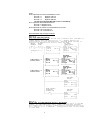
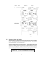
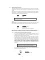
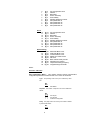
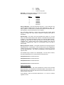
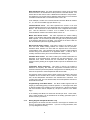
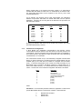
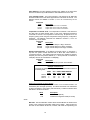
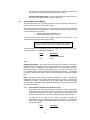
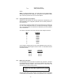
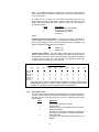
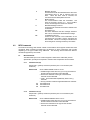
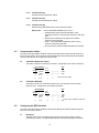
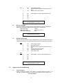
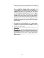
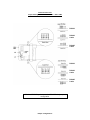
Corporate Office 1675 Chester Ave. Fourth Floor Bakersfield, CA 93301 (661) 716-5100 Phone (661) 716-5101 Fax 3100/3101- MTS Revision 1.60 3150/3151- MTS Revision 1.60 September, 1996 MTS Master Module ______________________________________________________ USER MANUAL Product Revision History 11/16/95 Revision 1.0 Initial release of product 08/24/96 Revision 1.6 Added support for Side Tank Indicator Table of Contents 1.0 Card Overview.....................................................................................................................................1 2.0 Programming the MTS Module ............................................................................................................1 2.1 Programming the MTS.....................................................................................................................1 2.1.1 3100-MTS Overview..................................................................................................................1 2.1.2 3150-MTS Overview..................................................................................................................1 2.1.3 Ladder Logic Considerations .....................................................................................................2 2.1.4 Making Modifications to the Example Ladder Logic....................................................................2 3.0 Processor to Module Data Transfer......................................................................................................4 3.1 Writing Data to the Module ..............................................................................................................5 3.1.1 Communications Configuration [Block ID Code 255]..................................................................5 3.1.2 Writing Register Data [Block ID Codes 0-79] .............................................................................8 3.1.3 Command List Configuration.....................................................................................................9 3.2 Reading Data from the Module.......................................................................................................11 3.2.1 Reading Module Register Data [ Block ID 0 to 79]....................................................................11 3.2.2 Reading MTS data from the Module ........................................................................................12 3.2.3 Master Error Code Table .........................................................................................................12 3.2.5 Error Status Codes..................................................................................................................13 4.0 MTS Commands ...............................................................................................................................14 4.1 MTS Commands............................................................................................................................14 4.1.1 Command 10h (16) .................................................................................................................14 4.1.2 Command 11h (17) .................................................................................................................14 4.1.3 Command 12h (18) .................................................................................................................15 4.1.4 Command 19h (25) .................................................................................................................15 4.1.5 Command 1Ah (26).................................................................................................................15 4.1.6 Command 1bh (27) .................................................................................................................15 4.1.7 Command 1Fh (31).................................................................................................................15 4.1.8 Command 20h (32) .................................................................................................................16 4.1.9 Command 21h (33) .................................................................................................................16 4.1.10 Command 18h (24) ...............................................................................................................16 5.0 Communication Cables......................................................................................................................16 5.1 3100/3150 to MTS Probe and STI ..................................................................................................16 5.2 3100/3150 to MTS DDA .................................................................................................................16 6.0 Configuring the MTS Hardware ..........................................................................................................16 6.1 MTS Probe ....................................................................................................................................16 6.2 MTS Level Plus DDA .....................................................................................................................17 6.3 MTS Side Tank Indicator................................................................................................................17 7.0 Support, Service and Warranty ..........................................................................................................17 7.1 Technical Support..........................................................................................................................17 7.2 Service and Repair ........................................................................................................................18 7.3 Warranty .......................................................................................................................................18 7.3.1 General Warranty Policy .........................................................................................................18 7.3.2 Limitation of Liability ...............................................................................................................19 7.3.3 Hardware Product Warranty Details ........................................................................................19 Appendix Example ladder logic for PLC and SLC Jumper Configurations 1.0 Card Overview The ProSoft Technology, Inc. 3100/3150-MTS products allow Allen-Bradley 1771 and 1746 I/O compatible processors to interface to MTS Systems Corporation instruments. The product includes the following capabilities: MTS Module The ProSoft MTS module can be user configured to support two MTS Master ports. Each port is fully and independently configurable, allowing the maximum in flexibility In addition to supporting the MTS Level gauges themselves, the ProSoft MTS product has also been tested with the DDA Level Plus Tank Monitoring System at speeds up to 19200 baud, and the Side Tank Indicator MTS Master Port • User configurable for Slave Address, Level Command, Temperature command. The Temperature commands can be selected to be on a User configured lower frequency polling scheme • Command codes: 16 Output Level 1 and 2 at 0.1 inch resolution 17 Output Level 1 and 2 at 0.01 inch resolution 18 Output Level 1 and 2 at 0.001 inch resolution 24 Send display command to STI 31 Avg & Indiv RTD Temp at 1 Deg F resolution 32 Avg & Indiv RTD Temp at 0.2 Deg F resolution 33 Avg & Indiv RTD Temp at 0.02 Deg F resolution • RS-422/RS-485 compatible for multidrop applications • Supports messages with or without checksum characters, automatically detecting the absence of a checksum • Software configuration Address : 192 to 255 (Probe Addresses ) Commands : As described above Parity : None, odd, or even (Even Normal) Stop Bit : 1 or 2 ( 1 is Normal ) Baud Rate : 300 TO 19,200 (4800 Normal) 2.0 Programming the MTS Module 2.1 Programming the MTS 2.1.1 3100-MTS Overview Programming of the 3100-MTS is less complicated than our previous products for the PLC-5 environment. Once all of the jumpers have been setup and the chip installed the module should be ready to configure and run. See section 3 for details on configuring the ports. Only one modification should be necessary to the ladder logic and that is to ensure that the Block Transfer instructions are set up for the correct rack and group (slot) address. 2.1.2 3150-MTS Overview The 3150-MTS comes with the lens cover and chip already installed. The only thing remaining is for the user to configure the port(s) to be used and to modify the sample ladder as necessary or implement logic of their own choosing. The port configuration registers are covered in detail in section 3.1.1. In order to implement the sample logic, the user must make sure that the correct 1 processor and rack size match up. Also, should it be necessary to re-locate the MTS module, the user should be certain to configure the correct slot as a 1746BAS 5/02 Configuration. Also, the user must be certain to configure the M0 and M1 files to be 64 word lengths each. The following is a step by step on how to configure these files using Allen-Bradley APS software. ICOM software users should follow similar steps. From the Main Menu: 1) Select the correct processor program and F3 for Offline programming 2) F1 for Processor Functions 3) F1 for Change Processor modify the processor here if necessary 4) F5 for Configure I/O the rack and slot configurations would be modified at this level 5) F9 for SPIO Config when the correct slot is highlighted 6) F5 Advanced Setup 7) F5 for M0 file length - type in 64 and Enter 8) F6 for M1 file length - type in 64 and Enter Esc out and save configuration 2.1.3 Ladder Logic Considerations Much of the simplification of the ladder logic is due to the fact that information is now either read or written from / to the module’s memory. The amount of data transferred to and from the module is controlled via the Read Data Block Count and the Write Data Block Count of the System Configuration registers. These parameters are used in conjunction with the ladder logic implemented. On power up the module moves a 255 into Word 1 of the BTR data file. This is a signal that the module needs to receive configuration data before proceeding any further. Once the configuration is received the module will begin transferring data to and from the processor depending upon how many Read and Write block counts have been configured. Once these are completed, the module will then transfer the command blocks if any have been configured. The sample logic assumes that Read data is stored in registers 50-99 (Block ID = 1) and data to be written is stored in registers 0-49 (Block ID = 0). It also assumes that 1 block of commands will be used (Block ID = 80). The following section discusses how to modify the logic If more data or commands need to be utilized. 2.1.4 Making Modifications to the Example Ladder Logic Should modifications to the sample logic be necessary, the user should take into account the following: 1) How much more data will be read (blocks of 50) 2) How much more data will be written to the module for writes (blocks of 50) 3) How many commands will be required The following example of expanded logic will accommodate 150 registers of data read, 100 registers to be written and 10 commands to slave devices. As the first step, you will need to modify the Configuration Parameters as follows: N7:0 N7:10 N7:20 0 1 2 3 4 5 6 7... 0 1 5 0 1 2 5 5 2 0 0 200 0 0 0 1000 0 100 0 0 - 0... 0... - 2 where: N7:20 represents the number of Read Block Counts Block ID = 2 Registers 100-149 Block ID = 3 Registers 150-199 Block ID = 4 Registers 200-249 (we will not be decoding Block ID’s 0 and 1...used below) N7:21 represents Write Data Block Counts Block ID = 0 Registers 0-49 Block ID = 1 Registers 50-99 N7:22 represents the number of Command Blocks to be used Block ID = 80 Commands 1-5 Block ID = 81 Commands 6-10 Next make ladder logic changes as follows: (SLC changes shown only) Rung 2:0 READ DATA FROM MTS MODULE This rung moves data from the M1 file (transfer file from MTS) to ladder memory when the Block ID is = 1. Module request for configuration is also received here. The BTW Block ID word is moved to the BTW Block ID word to setup the BTW. WRITE WRITE BT READ | ENABLE DONE DATA BLOCK | ID = 2 | | I:1.0 O:1.0 +EQU------------+ +COP------------+ | |--] [------]/[---+-+EQUAL +---+COPY FILE +-+ | 0 0 | |Src A M1:1.0| |Source #M1:1.2| | | | *| |Dest #N9:0| | changed to---> | |Src B 2| |Length 50| | 2 | | | +---------------+ | | +---------------+ | | | additional---> branch here additional---> branch here | BT READ | | DATA BLOCK | | ID = 3 | | +EQU------------+ +COP------------+ | +-+EQUAL +---+COPY FILE +-+ | |Src A M1:1.0| |Source #M1:1.2| | | | *| |Dest #N9:50| | | |Src B 3| |Length 50| | | | | +---------------+ | | +---------------+ | | BT READ | | DATA BLOCK | | ID = 4 | | +EQU------------+ +COP------------+ | +-+EQUAL +---+COPY FILE +-+ | |Src A M1:1.0| |Source #M1:1.2| | | | *| |Dest #N9:100| | | |Src B 4| |Length 50| | | | | +---------------+ | | +---------------+ | | ENCODES | | BLOCK | | | | +MOV-----------+ | +----------------------+MOVE +-+ | |Source M1:1.1| | | | *| | | |Dest M0:1.0| | | | *| | | +--------------+ | | USER CONFIG | | DOWNLOAD ENCODES | | SELECT BIT BLOCK | | | | B3 +MOV-----------+ | +----] [---------------+MOVE +-+ 0 |Source 255| | | |Dest M0:1.0| | *| +--------------+ Rung 2:1 WRITE DATA OR CONFIGURATION BLOCK TO MTS MODULE This rung moves data from the ladder logic data space to the MTS module. To add additional data, simply add more EQU branches. The command list to support a Master port is moved with Block ID 80 to support up to 5 commands. Configuration data is also moved to this rung. 3 WRITE WRITE DECODES WRITES ENABLE DONE BLOCK ID 0 BLOCK | I:1.0 O:1.0 +EQU------------+ +COP--------------+ | |--] [-----]/[----+-+EQUAL +-+COPY FILE +-+-| | 0 0 | |Src A M0:1.0| |Source #N10:0| | | | | *| |Dest #M0:1.1| | | |Src B 0| |Length 50| | | | | +-----------------+ | | +---------------+ | | DECODES WRITES | | BLOCK ID 1 BLOCK | | | | +EQU------------+ +COP--------------+ | +-+EQUAL +-+COPY FILE +-+ | |Src A M0:1.0| |Source #N10:50| | | | *| |Dest #M0:1.1| | | |Src B 1| |Length 50| | | | | +-----------------+ | | +---------------+ | | DECODES WRITES | | BLOCK BLOCK | | | | +EQU------------+ +COP--------------+ | +-+EQUAL +-+COPY FILE +-+ | |Src A M0:1.0| |Source #N10:100| | | | *| |Dest #M0:1.1| | | |Src B 80| |Length 50| | | | | +-----------------+ | | +---------------+ | additional---> branch here | DECODES WRITES | | BLOCK BLOCK | | | | +EQU------------+ +COP--------------+ | +-+EQUAL +-+COPY FILE +-+ | |Src A M0:1.0| |Source #N10:150| | | | *| |Dest #M0:1.1| | | |Src B 81| |Length 50| | | | | +-----------------+ | | +---------------+ | | DECODES WRITES | | BLOCK BLOCK | | | | +EQU------------+ +COP--------------+ | +-+EQUAL +++COPY FILE +-+ | |Src A M0:1.0|||Source #N7:0| | | | *|||Dest #M0:1.1| | | |Src B 255|||Length 30| | | | ||+-----------------+ | | +---------------+| USER CONFIG | | | DOWNLOAD | | | SELECT | | | B3 | | +---------(U)--------+ | 0 | | WRITE | | DONE | | O:1 | +---------------------( )---------------+ 0 3.0 Processor to Module Data Transfer Data transfers between the processor and the ProSoft Technology module occur using the Block Transfer commands, in the case of the PLC, and M0/M1 data transfer commands, in the case of the SLC. These commands transfer up to 64 physical registers per transfer. The logical data length changes depending on the data transfer function. The following discussion details the data structures used to transfer the different types of data between the ProSoft Technology module and the processor. The term 'Block Transfer' is used generically in the following discussion to depict the transfer of data blocks between the processor and the ProSoft Technology module. Although a true Block Transfer function does not exist in the SLC, we have implemented a pseudo-block transfer command in order to assure data integrity at the block level. Examples of the PLC and SLC ladder logic are included in Appendix A. In order for the ProSoft Technology module to function, the PLC must be in the RUN mode, or in the REM RUN mode. If in any other mode (Fault/PGM), the block transfers between the PLC and the module will stop, and communications will halt until block transfers resume. 4 3.1 Writing Data to the Module This section discusses how the transfer mechanism functions, and how to transfer data, command list, event driven write commands, and configuration data to the ProSoft module. Data transfer to the module from the processor is executed through the Block Transfer Write function. The different types of data which are transferred require slightly different data block structures, but the basic data structure is: Word 0 1-63 Description Block ID code Data In a PLC, the BTW length must be configured for 64 words, otherwise module operation will be unpredictable. Where: Block ID Code: A block identifier code between 0 and 255 in value. This code is used by the ProSoft module to determine what to do with the data block. Valid codes are: Code 0-79 80-99 255 Description Module Data Memory Command List Module Communication Configuration Data: The data to be written to the module. The structure of the data is dependent on the Block ID code. The following sections provide details on the different structures. 3.1.1 Communications Configuration [Block ID Code 255] The ProSoft Technology firmware communication parameters must be configured at least once when the card is first powered up, and any time thereafter when the parameters must be changed. On power up, the module enters into a logical loop waiting to receive configuration data from the processor. While waiting, the module sets the first word of the BTR buffer to 255, telling the processor that the module must be configured before anything else will be done. The module will continuously perform block transfers until the communications configuration parameters block is received. Upon receipt, the module will begin execution of the command list if present, or begin looking for the command list from the processor. Transferring the Communications Configuration Parameters to the module will force a reset of the communication port, as well as dropping DTR three times (200 ms pulses) to reset any attached hardware. The configuration data block structure which must be transferred from the processor to the module is as follows: Data Word Description Block ID Header = 255 Port 1 5 0 1 2 3 4 5 6 7 8 9 N[]:0 N[]:1 N[]:2 N[]:3 N[]:4 N[]:5 N[]:6 N[]:7 N[]:8 N[]:9 Port Configuration Word Address Baud Rate RTS to TxD Delay RTS off Delay Message Response Timeout Setup Parameter #1 Setup Parameter #2 Setup Parameter #3 Setup Parameter #4 10 11 12 13 14 15 16 17 18 19 N[]:10 N[]:11 N[]:12 N[]:13 N[]:14 N[]:15 N[]:16 N[]:17 N[]:18 N[]:19 Port Configuration Word Address Baud Rate RTS to TxD Delay RTS off Delay Message Response Timeout Setup Parameter #1 Setup Parameter #2 Setup Parameter #3 Setup Parameter #4 Port 2 System Config 20 N[]:20 21 N[]:21 22 N[]:22 23 N[]:23 24 N[]:24 25 N[]:25 26 N[]:26 27 N[]:27 28 N[]:28 Read Data Block Count Write Data Block Count Command Block Count Master Error Table Pointer Not Used Block Transfer Delay Counter Parameter Error Pointer Temperature Polling Frequency Integer/Floating Point Mode Where: For Port 1 and Port 2 Port Configuration Word : This register contains several communication configuration parameters encoded into the word. These are as follows: Type: The operating mode of the port is selected by these bits: Bits 3210 0000 MTS Master Stop Bits: The number of stop bits to be used is defined as follows: Bits 13 12 0 0 0 1 1 x One stop bit Two stop bits Invalid Port Configuration Parity: The parity mode to be used by the module is defined by this word as follows: Bits 15 14 6 0 0 0 1 1 0 1 1 No parity Odd parity Even parity Invalid Port Configuration Baud Rate: The baud rate at which the module is to operate. The baud rate is configured as follows: Value 0 1 2 3 4 5 6 7 Baud Rate 300 Baud 600 Baud 1200 Baud 2400 Baud 4800 Baud 9600 Baud 19200 Baud 38400 Baud RTS To TXD Delay: This value represents the time in 1 ms increments to be inserted between asserting RTS, and the actual transmission of data. The delay, if greater in duration than the hardware time delay associated with CTS, will override the CTS line until the time-out is complete. This configurable parameter is useful when interfacing with modem based devices, or anytime line noise must be allowed to subside before data is transmitted. RTS Off Delay: The value in this word represents the number of 1 ms time delay increments inserted after the last character is transmitted and before RTS is dropped. The module automatically inserts a one character width Off Delay, assuring that RTS does not drop until after the last character has been completely sent. Unless working under unusual conditions, this value will normally be configured with a value of 0. The maximum value to be used is 65535 (0xffff). Message Response Timout: This register represents the message response timeout period in 1 ms increments. This is the time which a port configured as a Master will wait before re-transmitting a command if no response is received from the addressed slave. The value is set depending on the expected slave response times. The allowable range of values is 0 to 65535(0xffff). If a zero value is entered, the module will default to a one second timeout value (1000 ms). Setup Parameter #1: Not used at this time. Setup Parameter #2: Not used at this time. Setup Parameter #3: Not used at this time. Setup Parameter #4: Not used at this time. System Configuration Read Data Block Count: This value represents the number of 50 word data blocks which are to be transferred from the MTS Module to the processor. The blocks returned from the module start at block 0 and increment from there. The maximum block count is 80. As an example, a value of 5 will return data blocks 0, 1, 2, 3, and 4, or module registers 0 to 249. 7 Write Data Block Count: This value represents the number of 50 word data blocks which are to be transferred from the processor to the MTS Module. The module will use this value to return a BTW Block ID Number to the processor. The ladder logic can use this value to determine which data to move to the MTS via the Block Transfer Write. The maximum block count is 80. As an example, if a value of 5 is entered, the MTS will return Block ID numbers 0, 1, 2, 3, and 4 to the ladder logic (See Section 3.2). Command Block Count: This value represents the number of 50 word Command Blocks which are to be transferred from the processor to the MTS Module. This value will be 0 if the module will not be configured with a Master port. See the discussion in Section 3.1.3 for details on the number of Command Blocks needed. The maximum block count is 20. Master Error Block Pointer: This value represents the relative starting position in the module's data register table within which the Master Error Data Block is placed. The error block (100 words in length) can be placed anywhere in the module’s data space (0 to 3999). The contents of the Error Table can then be obtained as part of the regular Register Data. Block Transfer Delay Counter: This value is used by the module to slow down the block transfer loading between the module and the processor. Excessive Block Transfers can slow down the response time of the MTS’s communication ports. This parameter has been provided to allow the Block Transfer timing to be determined on an application basis. A value of 100 is normally used at the factory and is recommended as a starting point. Parameter Error Pointer: This value is used by the module to determine the placement of the Parameter Error returned from the MTS instrument. The Parameter Error values returned from the instruments are placed in the module’s memory starting at the register location equal to the Parameter Error Pointer . Temperature Polling Frequency: This value is used by the module to determine the frequency with which the Temperature commands should be executed. Because process temperature changes tend to be relatively slow, it is often not as important to collect temperature data as level data. The frequency value is used to preset a down counter in the module. After each completion of the command list a counter is decremented. Once it reaches zero, the first temperature command in the command list is executed. The counter is then reset, and once decremented, the next temperature command in the list will be executed. Integer/Floating Point Mode Select: The MTS module supports both the Integer (0) and Floating point(1) modes of operation. In the integer mode, data is returned scaled by the resolution of the command (ie., values from devices with 0.02 resolution will be multiplied by 100 prior to transfer to the ladder logic). In the Floating Point Mode, two words are returned per value. These words, using a COP command, can be transferred to the floating point data space in the PLC and SLC processors. 3.1.2 Writing Register Data [Block ID Codes 0-79] [Moving data to the module has been reserved in case support is needed in the future to move data to MTS instruments. If you are not using this feature, then you may disregard this section] 8 Writing register data to the ProSoft Technology module is a simple Block Transfer Write with Block ID codes from 0 to 79 followed by 50 words of data. The actual data table starts at word 0 (Block ID #0, word 0), and is built incrementally after this. As an example, the following memory table demonstrates the relationship between the processor data table, the module data table, and the protocol addressing. Assuming we are using N10 as the data file in the processor, the data will map as follows: Proc Addr N10:0 N10:1 N10:2 -N10:49 N10:50 N10:51 -N10:99 Blk ID /Word 0/0 0/1 0/2 -0/49 1/0 1/1 -1/49 Module Addr 0 1 2 -49 50 51 -99 Protocol Addr 0 1 2 -49 50 51 -99 By paging the different data blocks into the module the processor can control the module data memory contents. 3.1.3 Command List Configuration A MTS Master port establishes communications and performs various communications functions based on the data which the user has placed in the command list. This list, entered into the processor Data Table, is transferred to the module's memory using Block ID codes 80-99 with each code representing a 50 word block, or 5 commands. The command list consists of up to 100 individually configured command data blocks (10 words reserved per command) which are shared between the two available ports (in the case when the module is configured with two Master ports). A command configuration block consists of the data necessary for the MTS Master logic to encode a valid MTS command, to transfer data from a slave to the master's memory, or to transfer data from the master's memory to a slave. The structure of the command configuration data block is as follows: Word 0 1 2 3 4 5 6 7 8 9 Description Port Select Slave Address Level Command Code Temperature Command Code Display Command Code (Future) (Future) (Future) (Future) (Future) where: Port Select: The Port Select parameter allows the application to select which port the MTS Module will use to execute the command. Valid values are: 0 1 2 Deselects the command Selects Port 1 Selects Port 2 9 Slave Address: The slave address represents the address of the slave MTS device to be talked to by the MTS Module. Valid addresses are 192 to 255. Level Command Code: The Level Command code entered in the table tells the MTS Module which of the three supported level commands to execute. The different choices are detailed in Section V, but in an overview they are as follows: Command Code Description 16d/10h 17d/11h 18d/12h Output Level 1 and 2 at 0.1 inch resolution Output Level 1 and 2 at 0.01 inch resolution Output Level 1 and 2 at 0.001 inch resolution Temperature Command Code: The Temperature Command code entered in the table tells the MTS Module which of the three supported temperature commands to execute. The temperature command may be placed into a low frequency polling mode using the Temperature Polling Frequency configuration parameter. The different commands are detailed in Section V, but in an overview they are as follows: Command Code Description 31d/19h Avg & Ind RTD temp at 1 Deg F resolution 32d/1Ah Avg & Ind RTD temp at 0.2 Deg F resolution 33d/1Bh Avg & Ind RTD temp at 0.02 Deg F resolution Display Command Code: If the Display Command Code is >0 (should be = 24) then the system module assumes that an MTS Side Tank Indicator is connected to the link. The module presumes that the STI’s address is offset by 64d(40h) from the level probes address (ie., a level probe with an address of 192d(c0h) will have an STI address of 128d(80h) ). Command Code Description 24d/18h Write Level and Temp to Side Tank Indicator Example Command List An example of multiple message configuration data blocks is shown in the following table: PORT SLV LEVEL TEMP DISPLAY NUM ADD CODE CODE CODE N10:50 2 192 16 31 24 N10:60 2 193 17 32 24 N10:70 2 194 16 33 24 Writing the Command List to the Module The Command List configuration data is written out to the MTS Module in 50 word blocks (five messages per block). This block size allows a full 1000 words of data to be written to the module (100 commands). The Block Transfer Write data block is structure as follows: Word 0 1-50 Description Block ID Code (80-99) Command Configuration Data (50 words) where: Block ID: The block identifier number allows the MTS Module to decode which portion of the command configuration table is being written. Valid numbers for the block ID are between 80 and 99, inclusive, with block 80 representing the 10 beginning of the command list and 99 representing commands 95 to 99. Block ID = 80 would correspond to the first five commands in the list. Command Configuration Data: The Command Configuration Data consists of the command list data outlined in the above discussion. 3.2 Reading Data from the Module This section discusses how to get data received from the slaves and the command error response codes from the module into the processor. The transfer of data from the ProSoft Technology module to the processor is executed through the Block Transfer Read function. Three basic different types of data are read from the module into the processor; • Module Register Data [ Block ID 0 to 79 ] • Configuration Request [ Block ID 255 ] The data structure for the block transfer depends on the type of block data. following sections detail the different types of data. The In a PLC, the BTR length must be configured for a length of 64 words, otherwise module operation will be unpredictable The ladder logic must be programmed to look at the BTR buffer, decode several words, and then take action. The BTR buffer definition is: Word 0 1 2-62 Description Block ID Code BTW Block ID Number Data Where: BTW Block ID Number: The module returns this value to the processor to be used to enable the movement of register data and command list blocks to the module. The BTW Block ID number is developed by the module based on the parameters entered in parameters 21 and 22 of Block 255 (See Section 3.1.1). This value is intended to only be a suggestion and to ease the ladder logic programming requirements. If it is desired to develop a different data transfer series, this may be easily accomplished in ladder logic. Data: The contents of the module’s Register Data space (0 - 3999). This data will contain data received from the slaves, data moved from the processor, and the Slave and Master Error Tables. The values will be 16 bit register values, and should be placed into integer files. Note that the user application ladder logic controls the placement and use of the data registers. 3.2.1 Reading Module Register Data [ Block ID 0 to 79] When a slave read command is executed by the Master, or when a Host writes to the MTS Module, the resulting data is placed into the ProSoft module data register space (Addresses 0 to 3999). This data space is transferred to the processor asynchronously, continuously updating the ladder logic data space. To make use of the data from the module, the ladder logic must be programmed to look at the BTR buffer, decode the Block ID and then take action. When transferring the Module Register Space Data, the BTR buffer is structured as follows: Word 0 Description Block ID Code 11 1 2-51 BTW Block ID Number Data ( 50 words of Data) Where: DATA: The Module Register Data. The values will be 16 bit register values, and should be placed into an integer file. Note that the user application ladder logic controls the placement and use of the data registers. 3.2.2 Reading MTS data from the Module Placement of data returned from the MTS instruments is determined by the Write Data Block Count configuration parameter and the relative placement in the Command List. The MTS data is located immediately after the Write data from the ladder logic (ie., with a Write Data Block Count of 2, the MTS data will begin at register 100). The precise position of the data is then determined by the slave’s position in the Command List. Ten words are reserved for each slave, with these words assigned as follows: Word 0 1 2 3 4 5 6 7 8 9 Description Level #1 Level #2 Temp #1 Temp #2 Temp #3 Temp #4 Temp #5 Temp #6 Future Future As an example, presuming that we have a Write Data Block Count value of 2, MTS data will then begin at register 100 in the module. The data table would be structured as follows: Register Range 100-109 110-119 120-129 130-139 3.2.3 Command List Position Slave #1 Slave #2 Slave #3 Slave #4 Master Error Code Table The MTS Module monitors the status of all Master port commands. This status is communicated to the processor in the form of a Master Error Code Table. Each Master command, whether in the command list, or event driven, will generate an Error Code for use by the user. The Master Error Code Table is initialized to zero on power up, and every time the module receives the 255 configuration data block. The Error Code Table is a 100 word block. The location of the Error Code Table is determined by the Master Error Table Pointer parameter in the Configuration 12 Block. The relationship between the placement of the error codes within the Error Table and the commands is according to the command’s relative position in the command list. To make use of the data from the module, the ladder logic must be programmed to look at the BTR buffer, decode several words, and then take action. When transferring the Slave Response Data, the BTR buffer is structured as follows: Word Description 0 Command List End of Poll Status 1 Command #1 Error Status 2 Command #2 Error Status Continued Where: Command List End Of Poll Status: This register provides an indication of when the Master has completed one cycle through the Command List. A bit in the word will be toggled each time the command list has been completed. The status is indicated for each master port as follows: Bit 0 Master Port 1 1 Master Port 2 Command Error Status: The Error Status Codes, either received from the slaves, or generated by the module, are placed in the table. See the next section for the meaning of the error codes. The values will be 16 bit values, and should be placed into an integer file. Note that the user application ladder logic controls the placement and use of these registers. Error Status Table Example Master Error Table Pointer = 150 Wrd Wrd Wrd Wrd Wrd Wrd Wrd Wrd Wrd Wrd 0 1 2 3 4 5 6 7 8 9 N10:150 0 0 8 0 0 0 0 0 0 0 N10:160 0 0 0 0 0 0 0 0 0 0 N10:170 0 0 0 0 0 0 0 0 0 0 N10:180 0 0 0 0 0 0 0 0 0 0 N10:190 0 0 0 0 0 0 0 0 0 0 N10:200 0 0 0 0 0 0 0 0 0 0 N10:210 0 0 0 0 0 0 0 0 0 0 In this case an error code of 8 was generated for command 2 -- all other commands were executed without any errors. Column 0 is used to identify that a master port has reached the end of the command list, and is starting at the top of the Command List 3.2.5 Error Status Codes The Error Codes returned in the Slave and Master Error Code Tables reflect the outcome of the commands and responses executed by the module. Note that in all cases, if a zero is returned, there was not an error. Valid Error Status Codes are as follows: Code Description 0 All OK The module is operating as desired. 1 Illegal Function An illegal command code request has been received 2 Illegal Data Address The address, or the range of addresses, covered by a request from the master are not within allowed limits 3 Illegal Data Value The value in the data field of the command is not allowed. 13 8 Message Time-out Communications with the addressed slave have been unsuccessful due to a lack of response from the slave. When this Error Code is received, the command has been attempted three times. Buffer Overflow The communications buffer has overflowed and reset the character counter to 0. If this condition occurs, the message size needs to be checked. Bad MTS Message Construct A message was received but the ETX character was not detected. Checksum Error The slave determined that the message checksum was in error, and therefore discarded the message TX Hardware Time-out A time-out has occurred in the transmission of the command from the master, and the command has been aborted. This error is usually an indication that the CTS signal is not being received by the module. 10 17 254 255 4.0 MTS Commands The ProSoft Technology MTS module Master communication driver supports several data read commands. When configuring a Master port, the decision on which command to use is made depending on the type of data being addressed. The following sections detail the different commands supported by the module. 4.1 MTS Commands The MTS Master port on the module supports a subset of the entire MTS protocol Specification, primarily those required to read and write Temperature and Level data. 4.1.1 Command 10h (16) Output level 1 (product) and level 2 (interface) at 0.1 inch resolution (with checksum) Data Format: T1: T2: T3: 4.1.2 <STX><dddd.d.d:dddd.d><ETX><ccccc> • Variable length record with one (1) to four (4) characters to the left of decimal character in each data field. • Fixed at one character to the right of each decimal character in each data field. • Level 1, level 2 data fields separated by ASCII colon (:) character. • Five (5) character checksum appended after ETX character. 350 milliseconds 530 milliseconds 46 milliseconds Command 11h (17) Output level 1 (product) and level 2 (interface) at 0.01 inch resolution (with checksum) Data Format: <STX><dddd.dd:dddd.dd><ETX><ccccc> • Variable length record with one (1) to four (4) characters to the left of decimal character in each data field. • Fixed at two characters to the right of each decimal character in each data field. 14 T1: T2: T3: 4.1.3 • Level 1, level 2 data fields separated by ASCII colon (:) character. • Five (5) character checksum appended after ETX character. 600 milliseconds 970 milliseconds 51 milliseconds Command 12h (18) Output level 1 (product) and level 2 (interface) at 0.001 inch resolution (with checksum) Data Format: T1: T2: T3: <STX><dddd.ddd:dddd.ddd><ETX><ccccc> • Variable length record with one (1) to four (4) characters to the left of decimal character • Fixed at three characters to the right of each decimal character in each data field. • Level 1, level 2 data fields separated by ASCII colon (:) character. • Five (5) character checksum appended after ETX character. 1.88 seconds 3.20 seconds 55 milliseconds 4.1.4 Command 19h (25) Average temperature at 1.0 degree F resolution Data Format: <STX><dddd><ETX><ccccc> • Variable length record with one (1) to four (4) characters • Five (5) character checksum appended after ETX character. T1: 1.0 + 0.9 seconds per RTD T2: Same T3: 25 milliseconds 4.1.5 Command 1Ah (26) Average temperature at 0.2 degree F resolution Data Format: <STX><dddd.d ><ETX><ccccc> • Variable length record with one (1) to four (4) characters to the left of decimal point • Fixed at one character to the right of each decimal • Five (5) character checksum appended after ETX character. T1: 1.7 seconds + 1.6 secs per RTD T2: Same T3: 30 milliseconds 4.1.6 Command 1bh (27) Average temperature at 0.02 degree F resolution Data Format: <STX><dddd.dd ><ETX><ccccc> • Variable length record with one (1) to four (4) characters to the left of decimal character • Fixed at two characters to the right of each decimal character in each data field. • Five (5) character checksum appended after ETX character. T1: 2.9 seconds + 2.7 secs per RTD T2: Same T3: 32 milliseconds 4.1.7 Command 1Fh (31) Pending command description of MTS. 15 4.1.8 Command 20h (32) Pending command description of MTS. 4.1.9 Command 21h (33) Pending command description of MTS. 4.1.10 Command 18h (24) Writes level and temperature data to LCD, without checksum. Data Format: 5.0 <SOH><ddd.dd:ddd.dd:ddd.d<ETX><ccccc> • Variable length record with three data fields. Three characters to the left of each decimal character in each data field.. • Fixed at three characters to the right of each decimal character in each data field. • Level 1, level 2 data fields separated by ASCII colon (:) character, followed by temp data • Five (5) character checksum appended after ETX character. Communication Cables The cable connection between the MTS module and the MTS probe is made through the ports on the front of the module. All connections to MTS hardware are made via RS-485, therefore please make sure that all ports are configured in RS-485 mode. 5.1 3100/3150 to MTS Probe and STI This cable connection is an RS-485 connection. Configuration of the cable is as follows: ProSoft Module 3100 3150 DB 25 M DB 9 F 14 TxRxD+ 1 25 TxRxD9 4 RTS 7 5 5.2 CTS 8 ------------------TxRx+ ------------------TxRx----| Jumper must be installed ----- 3100/3150 to MTS DDA This cable connection is an RS-485 connection (it can be 232 also but has not been tested as such). Configuration of the cable is as follows: ProSoft Module 3100 3150 DB 25 M DB 9 F 14 TxRxD+ 1 25 TxRxD9 4 RTS 7 5 6.0 MTS CTS 8 MTS --------------------------------------------| | --------- TxRx+ TxRxRTS Jumper must be installed on both ports CTS Configuring the MTS Hardware The cable connection between the MTS module and the MTS probe module is made through the ports on the front of the module. 6.1 MTS Probe The MTS probe must be configured via dip switches in the probe housing in order to communicate correctly. The dip switches that were used during testing were as follows: 16 SW 1 2 Off Off 3 Off 4 5 6 7 8 9 On On On On On On Power Supply Override Data Error Detect (3100/3150 will function with on also) Communication Timeout Timer Probe Address - C0 Hex is base Address (All on) Note that the MTS Probe should be Firmware Release 1.04 or later 6.2 MTS Level Plus DDA The DDA unit must be configured with the keypad interface in order to communicate. Some of the configuration settings that we used during our testing were: COM PORT BAUD 19200 COM PORT MODE MTS DDA( C0 to C7) COM PORT CHECKSUM OFF Note that the DDA should be Firmware Release 2.0 or later 6.3 MTS Side Tank Indicator The MTS Side Tank Indicator must be configured via two sets of dip switches in order to communicate correctly. The dip switches that were used during testing were as follows: SW 1 1 2 3 Off On Off 4 5 6 Off Off Off 1 2 3 4 5 6 On On On On On On Power Supply Override STI Operation Mode Data Error Detect (3100/3150 will function with on also) Communication Timeout Timer Temperature Display Units Level Display Units SW 2 Probe Address - 80 Hex is base Address (All on) Note that the STI should be Firmware Release 1.0 or later 7.0 Support, Service and Warranty 7.1 Technical Support ProSoft Technology survives on its ability to provide meaningful support to its customers. Should any questions or problems arise, please feel free to contact us at: Technical Support 17 ProSoft Technology, Inc. 9810 Camino Media Suite 105 Bakersfield, CA 93309 (805) 664-7208 (805) 664-7233 (fax) e-mail : [email protected] web : http://www.spft.com Before calling for support, please prepare yourself for the call. In order to provide the best and quickest support possible, we will most likely ask for the following information (you may wish to fax it to us prior to calling): 1. Product Serial and Version Number 2. Configuration Information Dip Switches Jumpers Communication cabling 3. MTS Instrument Information Type Command configuration, etc A BBS is available for the latest information on updates and new products. The phone number for the Bulletin Board is (805) 664-7234. Access is available 24 hours per day. In addition to 24 hour access to the BBS, an after-hours answering service (on the Bakersfield number) can patch you to one our qualified technical and/or application support engineers at any time to answer the questions that are important to you. 7.2 Service and Repair The 1500 card is an electronic product, designed and manufactured to function under somewhat adverse conditions. As with any product, through age, misapplication, or any one of many possible problems, the card may require repair. The 1500 product has a one year parts and labor warranty according to the limits specified in the warranty. Replacement and/or returns should be directed to the distributor from whom the product was purchased. If you need to return the card for repair, it is first necessary to obtain an RMA number from ProSoft Technology. Please call the factory for this number and display the number prominently on the outside of the shipping carton used to return the card. 7.3 Warranty 7.3.1 General Warranty Policy ProSoft Technology, Inc. (Hereinafter referred to as ProSoft) warrants that the Product shall conform to and perform in accordance with published technical specifications and the accompanying written materials, and shall be free of defects in materials and workmanship, for the period of time herein indicated, such warranty period commencing upon receipt of the Product. This warranty is limited to the repair and/or replacement, at ProSoft's election, of defective or non-conforming Product, and ProSoft shall not be responsible for the failure of the Product to perform specified functions, or any other nonconformance caused by or attributable to: (a) any misapplication of misuse of the Product; (b) failure of Customer to adhere to any of ProSoft's specifications or instructions; (c) neglect of, abuse of, or accident to, the Product; or (d) any associated or complementary equipment or software not furnished by ProSoft. Limited warranty service may be obtained by delivering the Product to ProSoft and providing proof of purchase or receipt date. Customer agrees to insure the Product or assume the risk of loss or damage in transit, to prepay shipping 18 charges to ProSoft, and to use the original shipping container or equivalent. Contact ProSoft Customer Service for further information. 7.3.2 Limitation of Liability EXCEPT AS EXPRESSLY PROVIDED HEREIN, PROSOFT MAKES NO WARRANT OF ANY KIND, EXPRESSED OR IMPLIED, WITH RESPECT TO ANY EQUIPMENT, PARTS OR SERVICES PROVIDED PURSUANT TO THIS AGREEMENT, INCLUDING BUT NOT LIMITED TO THE IMPLIED WARRANTIES OF MERCHANT ABILITY AND FITNESS FOR A PARTICULAR PURPOSE. NEITHER PROSOFT OR ITS DEALER SHALL BE LIABLE FOR ANY OTHER DAMAGES, INCLUDING BUT NOT LIMITED TO DIRECT, INDIRECT, INCIDENTAL, SPECIAL OR CONSEQUENTIAL DAMAGES, WHETHER IN AN ACTION IN CONTRACT OR TORT (INCLUDING NEGLIGENCE AND STRICT LIABILITY), SUCH AS, BUT NOT LIMITED TO, LOSS OF ANTICIPATED PROFITS OR BENEFITS RESULTING FROM, OR ARISING OUT OF, OR IN CONNECTION WITH THE USE OR FURNISHING OF EQUIPMENT, PARTS OR SERVICES HEREUNDER OR THE PERFORMANCE, USE OR INABILITY TO USE THE SAME, EVEN IF PROSOFT OR ITS DEALER'S TOTAL LIABILITY EXCEED THE PRICE PAID FOR THE PRODUCT. Where directed by State Law, some of the above exclusions or limitations may not be applicable in some states. This warranty provides specific legal rights; other rights that vary from state to state may also exist. This warranty shall not be applicable to the extent that any provisions of this warranty is prohibited by any Federal, State or Municipal Law that cannot be preempted. 7.3.3 Hardware Product Warranty Details Warranty Period : ProSoft warranties hardware product for a period of one (1) year. Warranty Procedure : Upon return of the hardware Product ProSoft will, at its option, repair or replace Product at no additional charge, freight prepaid, except as set forth below. Repair parts and replacement Product will be furnished on an exchange basis and will be either reconditioned or new. All replaced Product and parts become the property of ProSoft. If ProSoft determines that the Product is not under warranty, it will, at the Customer's option, repair the Product using current ProSoft standard rates for parts and labor, and return the Product freight collect. 19 APPENDIX A EXAMPLE LADDER LOGIC PLC-5 EXAMPLE LADDER LOGIC A-1 APPENDIX A(Cont'd) EXAMPLE LADDER LOGIC SLC EXAMPLE LADDER LOGIC A-2 Jumper Configurations Hardware Overview When purchasing the ProSoft product, there are two available choices for each platform. These choices are as follows: ProSoft Cat Num PLC SLC 3100 3150 3101 3151 Description Module provided by ProSoft Firmware only When purchasing the module from ProSoft Technology, many of the jumper configurations will have been factory set. When purchasing the firmware from ProSoft Technology and the Allen-Bradley module from another source, particular attention must be paid to hardware configuration. Module Jumper Configurations The following section details the available jumper configurations for the 1771 and 1746 platform solutions. As needed, differences between the module based solutions and the firmware based solutions are highlighted. 3100/3101 for the 1771 Platform Following are the jumper positions for the 1771-DB Rev B module and the ProSoft Technology 3100 module: Jumper JW1 JW2 JW3 JW4 JW5 JW6 JW7 JW8 JW9 3100 N/A N/A N/A Not Used 8 Pt Not Used Enabled RS-485 RS-485 3101 Enabled 32K PROM Turbo ASCII/ASCII 8 Pt Not Used Enabled RS-485 RS-485 JW1 Watchdog Enable / Disable Enable The position of this jumper does not affect the operation of the unit under normal operations. In order to enable the watchdog function, simply place the jumper in the Enabled position. JW2 PROM select 32K PROM The position of this jumper is very important to the successful operation of the module. In order to operate with our EPROM version, the jumper must be in the 32K PROM position. JW3 Speed select (Normal / Turbo) Turbo The position of this jumper does not affect the operation of the unit under normal operations. Unless there are reasons not to operate in the Turbo mode, we recommend operating in the Turbo mode. JW4 Port 1 and 2 configuration Position A The position of this jumper set must be changed from the shipped default position (D) to the A position. Operation of the module will be unpredictable if the jumper set is not in the A position. Jumper Configurations A B C D PRT 1 = ASCII PRT 1 = PGM PRT 1 = PGM PRT 1 = PGM DEFAULT PRT 2 = ASCII PRT 2 = ASCII PRT 2 = DF1 PRT 2 = ASCII DH485 = PGM DH485 = RUN DH485 = DISABLED DH485 = RUN JW5 Backplane 8/16 point 8 Point The module has only been tested in the 8 and 16 point modes and has successfully operated in both positions. We do however recommend the 8 pt position. JW6 Port 2 Baud Rate Not Used This jumper is not used by the firmware. All baud rate configuration is performed through the ladder logic data table. JW7 Battery Enable / Disable Enabled This jumper should be placed in the Enabled position when the module is powered up. Although not critical to the operation of the module, this will back up some data registers in the module during a power failure or reset. JW8/9 RS Configuration for Port 1 and 2 Set for RS-485 The default from factory is RS-232. Change the jumper to RS-485, or 2-wire mode. 3150/3151 for the 1746 Platform Following are the jumper positions for the 1746-BAS module and the ProSoft Technology 3150 module: Jumper JW1 JW2 JW3 JW4 3150 As Needed As Needed N/A N/A 3151 As Needed As Needed 3-5, 4-6 1-3, 2-4 JW1/2 RS configuration for port 1 and 2 See following diagram The default from factory is RS-232, but all options are supported by the firmware JW3 Memory Selection 3-5, 4-6 When using the 3151 firmware solution with a 1746-BAS module, the EPROM is plugged into the User Socket. When in this configuration, it is essential that the jumper be in the correct position. With the 3150 module, this jumper will not affect operation of the product. JW4 Mode Configuration 1-3, 2-4 When using the 3151 firmware solution with a 1746-BAS module, it is essential that the jumper be in the correct position. With the 3150 module, this jumper will not affect operation of the product. Jumper Configurations Communication Port Jumper Settings for 3150/3151 Modules - JW1 & JW2 RS-232 RS-422 4-wire RS-485 2-wire RS-232 RS-422 4-wire RS-485 2-wire For the 3150/3151 products, use the RS-485/2-wire jumper configuration Jumper Configurations Please Read This Notice Successful application of the MTS Module requires a reasonable working knowledge of the MTS Instrument hardware, and the application in which the combination is to used. For this reason, it is important that those responsible for implementing the ProSoft MTS Module satisfy themselves that the MTS Module and MTS Instrument combination will meet the needs of the application without exposing personnel or equipment to unsafe or inappropriate working conditions. This manual is provided to assist the user. Every attempt has been made to assure that the information provided is accurate and a true reflection of the product's installation requirements. In order to assure a complete understanding of the operation of the MTS hardware, the user should read all applicable MTS Systems Corporation documentation on the operation of their hardware. Under no conditions will ProSoft Technology, Inc. be responsible or liable for indirect or consequential damages resulting form the use or application of the MTS Module. Reproduction of the contents of this manual, in whole or in part, without written permission from ProSoft Technology, Inc. is prohibited. Information in this manual is subject to change without notice and does not represent a commitment on the part of ProSoft Technology, Inc. Improvements and/or changes in this manual or the product may be made at any time. These changes will be made periodically to correct technical inaccuracies or typographical errors. PLC and SLC are registered trademarks of Allen-Bradley Company Inc.