1
CamTrace
Network video surveillance server
Installation
V 6.11.x - V 5.11.xx
18/06/2012
English
1 INSTALLATION - CONFIGURATION
For additional information:
www.camtrace.com
Copyright 2000-2012, Camtrace SAS
Camtrace SAS, 92150 Suresnes, France
3
1 INSTALLATION - CONFIGURATION__________________________________________3
1.1 Startup - connection - Shutdown.............................................................................................. 6
1.1.1 Standard start-up and shutdown............................................................................................................6
1.1.2 Startup and shutdown without screen...................................................................................................7
1.2 IP Configuration of CamTrace server......................................................................................8
1.2.1 Default addresses.......................................................................................................................................8
1.2.2 Data collection for connection to an existing network.....................................................................9
1.2.3 General information about the CamTrace network settings.............................................................9
1.2.4 Manually set the network parameters..................................................................................................9
1.2.5 Adjusting system parameters................................................................................................................10
1.2.6 Using the setup wizard.............................................................................................................................11
1.3 Camera configuration............................................................................................................. 11
1.3.1 Configuring the IP address of each camera.....................................................................................11
1.3.2 Camera configuration...........................................................................................................................12
1.3.2.1 Checklist of operations to be performed on each camera....................................................12
1.3.2.2 Additional time parameters...........................................................................................................13
1.3.2.3 Limiting camera bandwidth...........................................................................................................13
1.4 CamTrace startup and configuration.....................................................................................13
1.4.1 Service startup.........................................................................................................................................13
1.4.2 Installation of putty terminal emulation – network access to menucam.....................................15
1.4.3 Declaring cameras in the CamTrace server......................................................................................15
1.4.3.1 Manual declaration of cameras .................................................................................................15
1.4.3.2 Compatibility mode with previous versions of CamTrace.......................................................18
1.4.3.3 Choice of acquisition parameters in H264 or mpeg4 mode..................................................18
1.4.3.4 Limitations to be aware of for H264 and mpeg4......................................................................19
1.4.3.5 Recommended scenario for H264 megapixel mode..............................................................19
1.4.3.6 Choosing a camera model...........................................................................................................19
1.4.3.7 Automatic declaration of cameras............................................................................................19
1.4.4 Client workstation configuration and operations check.................................................................20
1.4.5 Interpretation of status messages in CamTrace.................................................................................20
1.4.6 Save the server configuration on a client workstation.....................................................................21
1.4.7 Check CPU load and system parameters...........................................................................................21
1.5 Configuring remote access................................................................................................... 22
1.5.1 Router/firewall configuration................................................................................................................22
1.5.2 CamTrace server configuration.............................................................................................................23
1.5.3 Limiting the bandwidth to the outbound gateway...........................................................................24
4
1.6 Supervisor configuration.......................................................................................................... 24
1.6.1 Configuration of remote CamTraces...................................................................................................25
1.6.2 Configuration on the CamTrace Supervisor........................................................................................26
1.7 Cluster – unified interface configuration................................................................................28
1.7.1.1 Configuration to be performed on all the servers of the cluster.............................................29
1.7.1.2 Configuration to be performed on client workstations.............................................................29
1.7.1.3 Configuration to be performed on the connection servers.....................................................29
1.8 Display screens........................................................................................................................ 30
1.8.1 Slave screen configuration.....................................................................................................................30
1.8.2 Pilot display on a slave screen...............................................................................................................31
1.8.3 Case with a slave multiscreen workstation..........................................................................................31
1.9 Management of camera options........................................................................................... 32
1.10 Positions and patrols of motorized cameras......................................................................33
1.11 Install the camIO module inputs/outputs...........................................................................33
1.12 Create a shortcut on the desktop.......................................................................................35
1.13 Multivolume management.................................................................................................. 36
1.14 Graphic mode on the console............................................................................................ 37
5
1.1 STARTUP - CONNECTION - SHUTDOWN
1.1.1 Standard start-up and shutdown
CamTrace is generally delivered without a screen.
Ensure that you have a VGA screen for the first installation procedure.
Remove the server from its packaging, connect it to the screen (not provided) and
to the keyboard. You do not need to use the mouse for installation, but you can use
the mouse in the event of use of graphical mode on the console.
To safeguard against power cuts, during operation, you should install a UPS to supply
CamTrace. Once it is equipped with a power supply, you can start your server.
CamTrace behaves differently during the initial startup (from "factory" settings) or
during starts (boots) that follow.
In all cases a series of text messages will appear on the screen
If the machine has just been delivered (factory settings) a menu lets you choose
between English and French. This is only to choose the language of the menu itself.
CamTrace then allows you to customize the keyboard you use (localization). Choose
the appropriate keyboard in the list. You can modify this choice later.
If you already booted before, the CamTrace logo (an eye) appears
The system beeps three times (useful if you are booting without a screen).
The login: prompt appears.
Enter the name of the system administrator and the default password.
Careful: when entering the password, it does not appear on the screen.
Login: root Enter
Password: camtrace Enter
The system administrator command prompt appears:
Machine_name #
Type 'menucam' to open the CamTrace service and configuration management
menu.
The CamTrace server is designed to operate 24h/24; never shutdown the server by
unplugging the power cable or by turning off the power switch (incorrect server
shutdown could damage certain files).
To shutdown the system:
• Open your administrator session
(default login "root" / password "camtrace" )
• Enter the "menucam" command and press [Enter].
• Go to "System shutdown " and validate,
Note : To move up the menucam menu hierarchy, press: Esc Esc
6
Note : If you are in graphical mode, you can go to the main console by pressing the CTRL, ALT
and F1 keys simultaneously. You can then start the menucam.
To return to graphical mode, press the CTRL, ALT and F1 keys.
To exit graphical mode, press the CTRL, ALT and BACKSPACE () keys.
There is also an alternative procedure for shutting down the system:
− Press the CTRL, ALT and DEL keys simultaneously to trigger a system restart (reboot).
− Or (if this function exists) press briefly on the reset button on the machine.
− If you wish to shutdown the machine, turn the power supply off when the word
"rebooting" appears on the screen.
1.1.2 Startup and shutdown without screen
You can also configure CamTrace without a screen. One CamTrace network output
has a default address of 192.168.1.100. You can connect to CamTrace and
configure using terminal emulation via a portable PC for example.
To do this, start up CamTrace and wait for the three beeps that indicate reboot is
complete. Place your PC on an address on the network 192.168.1.0 (for example
192.168.1.2). Link the PC using a crossed cable to a network interface (at random).
Ping the server. If it does not respond, change the network connector and ping until
you find the good interface. See "Access Menucam via the network" below.
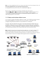
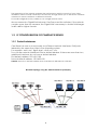
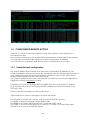
Note: CamTrace has one or more network cards (usually two): You can mix cameras and
display stations on all networks at will. But we recommend that you create ‘specialist’
networks, particularly for important setups. In this way, you can group cameras on one or
more security networks, use another network interface to connect to the company’s network
and yet another to connect to a display network (guard houses and display PCs).
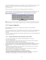
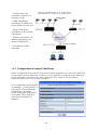
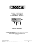
CamTrace installation overview
7
This separation of the network optimizes the performance and the security of your video
installation. When several CamTraces are used we strongly advise you to isolate the cameras
attached to each CamTrace on different networks.
For small configurations it is possible to use a single network card.
We recommend a Gigabit link between CamTrace and the switches. If the network
contains more than ten cameras, the Gigabit link is necessary to obtain fluid images
in 640 x 480 or higher formats.
1.2 IP CONFIGURATION OF CAMTRACE SERVER
1.2.1 Default addresses
CamTrace has one or more (usually two) Ethernet network interfaces, RJ45 ports,
labeled by the name they have in the operating system.
For example : em0, em1, bge0, bge1, reo0, reo1, etc.
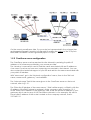
Two of these network interfaces have a default address. If there are more than two,
additional interfaces do not have a default address.
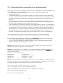
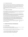
First default address: 192.168.1.100
Second default address: 192.168.0.100
Careful: there is no default address when CamTrace is delivered as software.
Network topology using the default addresses (example)
8
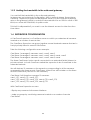
1.2.2 Data collection for connection to an existing network
If you must connect the CamTrace video server to an existing company network, you
will need the following information:
• An IP address for your CamTrace server on the company network side.
• The network mask.
• A network name for the CamTrace server. The "network name" is the name that
you give to the CamTrace server on the local network. If the company has a DNS,
we recommend that its name be consistent with that given to the CamTrace in
this DNS.
• The IP address of an internal or external DNS. This parameter is optional. It is used
by the CamTrace server to reach external names with their names (FQDN) and
not only their IP addresses (for example, mail server)
• The IP address of the default gateway: This parameter is optional. It is required to
reach the CamTrace server from a client workstation located outside the segment
on which the CamTrace server is located. For example, to access a CamTrace
via the Internet, you must enter the IP address of your router on the local network
side (LAN). It is also used by CamTrace to "exit" the address class of the local
network (for example, connection to an NTP time server, or to an email server).
1.2.3 General information about the CamTrace network settings
Pour configurer les paramètres réseau depuis menucam, il existe deux méthodes,
• You can configure CamTrace manually with menucam.
• You can use the installation wizard that allows you to define the network and
system settings by answering key questions.
Caution: If the address class of the name server (DNS) is different from those used on the
CamTrace networks, the gateway must be filled in.
Caution: You must assign two addresses to CamTrace belonging to different networks. To
avoid serious malfunction of your CamTrace network, you must never use the same address
class on both interfaces.
Examples of CamTrace addresses:
Camera side
Company side
192.168.0.111
192.168.0.112 incorrect
192.168.0.111
192.168.1.112 good
192.168.0.111
192.168.1.111 good
Note: If you use CamTrace on a single network, be sure to leave blank the values defined for
the other networks. In "Network configuration / Network interface configuration" leave blank
(or delete) the fields corresponding to the unused network interface
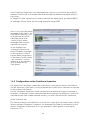
1.2.4 Manually set the network parameters
Open an administrator’s session: login "root" password "camtrace".
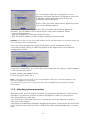
Enter "menucam" then press Enter.
The following screen appears:
9
Go to the menu "Network configuration". In the
submenu "Network interface configuration" enter the
IP address, mask values and leave empty the
maximum bandwidth state.
Then in "Set host name, name server, gateway" enter
the values obtained above.
In the "Set host name, name server, gateway"
submenu, the "IP address of the Name server" field, can be filled as follows :
- Leave the field empty.
- Type the IP address of the internal DNS if it exists.
- Type the DNS IP address of the company Internet service provider.
Attention: If you are not sure of the DNS address, leave this field empty. An incorrect value will
slow CamTrace down considerably.
Once you have entered the required information, the IP addresses and the
connection status (100 full or 1000 full) appear in the upper part of the "Network
configuration" menu.
To test the configuration, go to the "Quit" menu and perform a ping on the IP address
of a local network station:
# ping station_IP_address enter
To stop the ping, enter CTRL C
Note : CamTrace cannot "ping" a host with its Netbios name (the one that appears in the
Microsoft neighborhood network).
The CamTrace server does not appear in the network neighborhood of Microsoft client
workstations.
1.2.5 Adjusting system parameters
With Menucam, you can adjust a number of parameters required for correct server
operation. In particular, with the "System configuration" menu you can set the
CamTrace time zone and time.
You must first be in the right time zone. Choose the continent and the country in
which you are located.
CamTrace automatically manages daylight saving times. Simply enter the local time
in the "Set the date and time" menu. BIOS will be automatically adjusted in universal
time.
10
1.2.6 Using the setup wizard
The setup wizard will guide you step by step during installation. If you are not familiar
with CamTrace, it will prevent you from forgetting an important step.
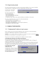
In menucam, choose the
setup wizard - choice 8 The setup wizard lets you
choose respectively:
- the menus language
- the console keyboard language
- the server's time zone
- IP addresses and masks of the network interfaces available on the server
The setup wizard then lets you choose optional parameters:
- the server name on the network
- the domain name server (DNS) address
- The address of the gateway
- the maximum bandwidth allowed through the gateway
- the address of a time server (NTP)
1.3 CAMERA CONFIGURATION
1.3.1 Configuring the IP address of each camera
Each camera must have a fixed IP address on the network. For historical stability
reasons for addressing, CamTrace is not a DHCP server.
Attention You must always define the IP address of a camera and check its operations before
placing it in an area difficult to access (pole, housing, etc.).
There are two methods for defining the IP address for each camera.
a) Configuration offered by the camera manufacturer.
This is the standard configuration valid for all camera brands.
Configuration software is always provided with the cameras: IP Utility - IP Finder, IP
setup, etc, depending on the manufacturer.
Install the utility on a PC connected to the network on which the cameras are found.
Most utilities automatically detect the network cameras. You need only provide the
IP address and occasionally other parameters depending on the manufacturer.
b) Configuration using the
CamTrace server.
In menucam, choose "Camera
configuration" and then "Set the
network address of a camera".
The program asks you to enter
the MAC address of the
11
camera (this address is marked on the camera), then the IP address that you wish to
assign to it. When you enter the MAC address, separate each group of two
characters with ":".
Switch off the power supply to your camera and then turn it back on.
To check the network connection for the camera that you have installed, you can
perform a "ping" on the allocated address, from the CamTrace server (on the
console or from a remote terminal). To do so, exit the menucam and enter:
#ping camera_adress enter
List of active cameras
Note: sub-menu 1 "list active cameras" indicates the list of cameras recognized as active (IP,
model, description, version, name). This function may not work for certain camera models.
1.3.2 Camera configuration
Each camera model has its own configuration. Refer to the manufacturer’s
documentation.
To test the camera that you are installing, check that you have an animated image
that appears in the browser using a PC connected to the same network as this
camera.
You can fine-tune configuration and image quality at this point or after declaring the
camera in CamTrace.
1.3.2.1 Checklist of operations to be performed on each camera
- Give a fixed IP address to the camera. Check that DHCP is not active.
- Fill in the network mask.
- Enter the administrative logins and passwords for the camera (certain cameras
have default passwords, others must be entered).
- In the video settings, configure the camera in mjpeg mode (to start).
From CamTrace V x.10.x it is possible to capture a video stream in MPEG4 or H264.
Specific settings of these modes are explained below and in the administration
manual.
- Enter the gateway address that is the address of the CamTrace on the network
where the camera is to be connected.
- Enter the address of the NTP server that is the same as the previous address.
- Display the time in the image (recommended).
- Set the time zone and adaptation to winter/summer times.
- Limit the bandwidth of the camera to that which is necessary.
- Settings concerning image quality, obturation speed, compression, image size,
lighting type, backlighting, etc. can be provided at a later date.
12
1.3.2.2 Additional time parameters.
CamTrace is an NTP server (synchronization server for all peripherals that are NTP
clients). To synchronize cameras on CamTrace, you must activate the "synchronize
with NTP server" option in each camera. In the address field of the NTP server, you
must enter the CamTrace address on the camera network (192.168.0.100 in our
example). If the camera is located on the company network you must enter the
CamTrace address on the company network side.
For image authentication reasons, we highly recommend you display the time in the
image.
1.3.2.3 Limiting camera bandwidth
As recent cameras can be used for ever-higher resolutions, they can take up 10 to 12
Mb of bandwidth on the network (images of 100 KB at 30 i/s) in mjpeg mode, and 2
to 3 Mb in H264 mode with megapixel images.
The bandwidth used between CamTrace and each camera is adjusted on the
cameras themselves.
It is often useful to limit the bandwidth sent by cameras. This prevents saturation of
the CamTrace network card(s) that receive the camera flows. In reality this often
leads to increased fluidity. This method is indispensable if the cameras are located
on a company network. Use values between 2 Mb and 5 Mb.
On certain cameras, adjustment takes place in the TCP/IP section, sometimes in the
"advanced parameters" section. Enter the desired value in "maximum bandwidth".
On other cameras, you can only limit the number of images per second.
Note that on certain camera models, this type of adjustment does not exist.
For cameras using H264 codec, you should adjust the camera settings to CBR
(Constant bit Rate) if there is any doubt concerning the total capacity of the
network to support VBR (variable bit rate).
You can also limit the overall network bandwidth for cameras directly in CamTrace.
Access this function via Menucam in "Network configuration " → " Network
interface configuration".
1.4 CAMTRACE STARTUP AND CONFIGURATION
1.4.1 Service startup
Activate the following services in menucam:
Go to "CamTrace Services", then to submenu "Start all inactive services". CamTrace
starts the web server, the database and the video service.
You can now access, using a network station, the web interface of the CamTrace
server by entering the following in the address bar of your browser:
"http://CamTrace IP address on the company network "
if you are on a company network station (usually the case).
• "http://CamTrace IP address on the camera network "
if you are on a station located on the camera network.
•
13
•
"http://CamTrace IP address on the surveillance network " if you are on a station
located on the surveillance network.
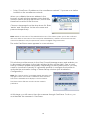
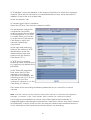
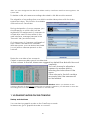
When you validate the server address in the
browser, a login window appears. Note that this
window calls on the pop-up function, which must
therefore be active in the browser.
Choose a language from the drop-down list. Enter
'admin' and 'camtrace' for the user name and
password respectively.
Note: Admin is the name of the administrator user of the video system (not to be confused
with root which is the name of the computer administrator). Admin is a reserved user that
cannot be deleted. Only the password can be changed using menucam.
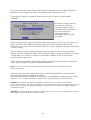
The main CamTrace menu appears in a new window:
This window provides access to the View/Consult/Manage menus and enables you
to disconnect and return to the login window (button on the right). One or more
start-up windows appear temporarily. Depending on the browser version, you may
need to close them manually. It is generally possible to configure the browser to
authorize the automatic closing of these startup windows (see Workstation
Configuration).
Note: The “Server active” message should appear in the
top right corner of the main CamTrace menu window.
This zone is clickable and displays a status window.
The three status LEDs are used in cluster mode in
particular.
At this stage, you still cannot view the cameras through CamTrace. To do so, you
must declare the cameras in CamTrace.
14
1.4.2 Installation of putty terminal emulation – network access to
menucam
Note: You can skip this paragraph if you don’t want to access menucam from your PC. If,
however, you need to administer CamTrace from a distance, you must install the putty
emulation software described below and configure the router to allow entry to port 22.
The putty emulation software (for PC / Ms Windows) is provided with CamTrace – you
can easily install and configure it. Go to the main menu (banner) of the web
interface. Click on "Help", then on "Utilities". Click on PUTTY to download it, then click
on "recommended configuration" to configure it. When you call putty, a "putty
configuration" window appears on the screen. Enter the name of the CamTrace
server or its IP address in the Host Name fields. Port 22 is used and the protocol SSH
(secured). Then enter Load and Open. The emulation window opens on the screen.
The security procedure requires a two-step login:
login as: camtrace
camtrace@machine_name password: camera
$ su
Password: camtrace
Machine_name #
Note: The passwords provided are default passwords. The "camtrace" user is an ordinary
computer user (without root privileges) the password of this user is: camera
the "su" command switches the user to a "super user" (root) whose password is: camtrace.
1.4.3 Declaring cameras in the CamTrace server
There are two ways to declare cameras: A manual procedure that works with all
cameras supported by CamTrace and an automatic procedure using the
menucam, that will work with certain cameras (Axis, Sony, Mobotix, CamIP). Certain
models and/or firmware may not be recognized.
1.4.3.1
Manual declaration of cameras
This general procedure is accessed via the CamTrace web interface.
Go to the "Administration" menu and then "Cameras". In the top left of the menu,
click on ‘’Add a Camera’’
15
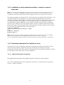
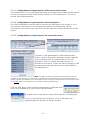
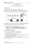
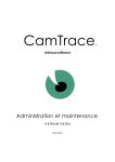
Add/modify a camera. Parameters are organized as tabs.
Camera declared in http mjpeg format
Camera declared in rtsp h264 format
Note: With the admin/camera menu you can change the parameters on more than one
camera at a time. If you have a number of identical cameras we recommend you use
‘recognition/automatic addition by Menucam’ then use the left column of the
‘admin/camera’ menu to select all those that will have the same parameters. Then click on
"modify the selection" at the top of the menu. The "modify several cameras" window opens.
Attention: some of the parameters in the "acquisition" tab can only be modified globally if the
cameras are of the same model.
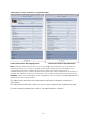
The table below describes the parameters required to integrate a camera in
CamTrace.
The add and modification menus for one or more cameras are organized by tabs.
For the remaining parameters, refer to the administration chapter.
16
General tab
Camera name
Network address
Name you wish to give the camera.
Enter the camera IP address.
Acquisition tab
Camera type
PTZ
Choose a camera model in the list. If it is not mentioned, choose
the closest model.
Select this case if the camera can be piloted (motorized or
virtual PTZ).
Image size
Choose the image size from the values available (if the camera
allows this). "Set up camera" corresponds to the size
(resolution) defined in the camera.
Image compression
Choose the image compression from the values available (if the
camera allows this). "Set up camera" corresponds to the
compression defined in the camera.
Video channel
For a multichannel camera server, specify the channel number
from the values available.
Protocol to use
http : this protocol only supports mjpeg format. It is compatible
with all previous versions of CamTrace.
Encapsulation rtsp
rtsp : new protocol compatible with the h264 format - also
manages the mpeg 4 and mjpeg for some cameras.
The rtsp encapsulation field appears only if the rtsp was
chosen. The default parameter is std (see a description of all
cases below).
Login for HTTP camera
authentification
Password for HTTP camera
authentification
Record permanently
Frequency of perm. recording
Storage space
Other parameters
Enter the access login for the camera administration interface.
See the current logins below.
Enter the password for the camera administration interface. See
the default passwords below.
Records tab
Choose a schedule that can be applied to permanent
(continuous) recordings for this camera. Choose "always" to
record permanently and "never" for no recording. Specify a
recording frequency, eg : 6 images/sec.
If you have more than one disk volume choose the one on which
the camera will be registered. Please note that to modify this
parameter you will need to erase all the images on this camera.
Leave the default values for the moment.
Note: login and default passwords used by the main manufacturers
Axis Communications: root pass (Recent Axis cameras do not have a default password, you
must enter one when you connect for the first time).
Sony: admin admin
Mobotix: admin meinsm
Panasonic: viewer password
CamIP: admin admin
IQeye: root system
17
1.4.3.2
Compatibility mode with previous versions of CamTrace
With CamTrace, you can operate all cameras supported by its earlier versions. To use
"traditional" CamTrace mode, choose http protocol. For certain earlier camera
models, only this mode is offered in the acquisition interface.
1.4.3.3
Choice of acquisition parameters in H264 or mpeg4 mode
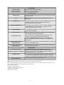
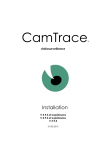
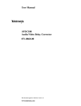
The most usual case: rtsp protocol and std encapsulation (OnVif standard).
In OnVif standard, the images are transported in RTP/UDP mode and the commands
in RTSP/TCP mode (see the diagram below).
This mode covers most cameras operating in RTSP/H264 mode.
Axis Communications cameras configured in H264 or mpeg4 mode
Sony H264 - Panasonic H264 - Pelco H264 - Bosch H264 cameras.
Vivotek H264 Cameras - CamIP H264 cameras with firmware 1.0.26 and +
In certain cases and only for cameras that support this, you can use two other
protocols:
rtsp transported exclusively in tcp. in this case, the images and the commands are
transported by TCP – this is useful for networks that lose too many UDP packets but is
slower than rtsp std mode
rtsp encapsulated in http (http tunnelling). This mode is used to bypass certain
firewalls. The transport layer is TCP. This is the slowest of the three rtsp modes.
Modes
OnVif = rtsp on UDP and TCP
Protocols
RTP
Transport
UDP
rtsp on TCP
Tunnelling rtsp on http
RTSP
RTSP
HTTP
TCP
For Axis Communications cameras and certain Panasonics, compression and format
(resolution) are directly adjustable in the CamTrace "acquisition" tab. For all other
cameras the acquisition URLs are established, so these two fields specify "camera
setup" and these two parameters must be set in the camera.
For previous cameras CamIP HRI, HAI and HDRV cameras, (Mjpeg/Mpeg4 cameras
without H264 support, operating with firmware in version3.2.x and higher), use the
"HDXP" model (also valid for HTXP cameras). If the cameras are configured in mpeg4
use: rtsp, std in administration / camera, acqusisition tab.
If the cameras are configured in Mjpeg, select chv1 in "feed transport" in the
"acquisition" tab.
For the oldest CamIP cameras CamIP HRI, HAI, HDRV operating with firmware in
version 2,x,x., you can use only Mjpeg. In this case select chv1 in "feed transport" in
the "acquisition" tab.
18
1.4.3.4
Limitations to be aware of for H264 and mpeg4
When you use a camera in H264 or mpeg4 mode, you must be aware of certain
limitations inherent to these formats.
- The acquisition, recording and display rate of a flow must be the same. To decrease
the recording rate you must act on the source, that is, the camera.
- Insufficient bandwidth on the camera network can trigger deterioration in
recording with loss of images.
- In play mode, H264 flows are accessible using a browser via the CamTrace Viewer
activeX/plugin from a Windows station only. H264/mpeg4 flows cannot be displayed
on the CamTrace console, on a Mac, on a Linux workstation or on a mobile.
1.4.3.5
Recommended scenario for H264 megapixel mode.
- Configure a high resolution flow of 12 i/s (or higher) for recording and for individual
displays.
- Plan for a second low resolution flow in MJPEG mode in a 640x480 or 320x240 format
for a mosaic display and remote access via Internet or mobile.
This second flow could be recorded at 3 i/s for motion indexing, access to the digital
video player from the mobile application or for viewing and display on the console.
1.4.3.6
Choosing a camera model
The different supported camera models are predefined in CamTrace. Choose from
the list that appears. New camera models are regularly added.
Camera brands supported (non-exhaustive list): Alinking, Axis Communications,
Bosch, CamIP, Cell, Grand, Hunt, Mobotix, Panasonic, Pelco, Pixord, Sony, Vivotek.
Please note that not all the models in these brands are necessarily supported.
Contact your installer for more details.
When choosing the "camtrace" camera model, you can receive a video flow from
another CamTrace in order to sequence and prioritize CamTrace servers in relation
to each other.
Note: the models also describe the IP converters (or camera "servers") that CamTrace ‘sees’
as cameras.
1.4.3.7
Automatic declaration of cameras
Note: Cameras must be previously connected to the network with their IP address and their
mask correctly defined. To do this, use the manufacturer’s installation software.
This function is activated using the menucam on the console or via a network station
equipped with terminal emulation (for ex. putty).
Start menucam. Go to "Camera configuration" then to "Automatically add cameras
to the database". CamTrace will automatically detect the new cameras located on
all networks to which it is directly connected, will enter them in the database with a
19
default name (cammodel_lastdigit-of-IP-address) and choose the most adapted
camera server type.
Note: This function may not operate with certain cameras or may be filtered by routers
In this case, you must declare these cameras manually with the procedure seen above.
1.4.4 Client workstation configuration and operations check
At this stage you can display a camera in CamTrace via your local network.
In the CamTrace web interface, click on "View" and then on "Single camera". The list
of cameras that you have installed appears.
Choose one of these cameras. It must appear on the screen in a separate window.
The first time you connect to a camera from a given client station, an active X/plugin
will be downloaded. You must accept installation. Your client station must therefore
accept active X (for Internet Explorer) or plugins (for Firefox).
Moreover, whether you are working with IE or Firefox/Mozilla, the client station must
accept cookies and pop-ups from CamTrace.
In case of a problem refer to the section "problems and solutions".
If the window appears but if you do not have an image, check that you do not have
a firewall active on the client workstation. If so, ports 8000, 8001 and 8002 must be
open in output mode.
Irrespective of your browser you should add CamTrace to the trusted sites. For
example, with I.E.: Tools/Internet options/Security tab/add the address or the
CamTrace name (if you have a DNS), being sure that https checkbox is not checked.
Note: When CamTrace is used from Internet Explorer, a status bar may appear masking the
end of CamTrace menus. To remove it, simply place CamTrace in the Internet Explorer
confidence sites. If the same problem arises under Firefox please refer to the "problem and
solutions" chapter.
1.4.5 Interpretation of status messages in CamTrace
The CamTrace web interface provides a global view of all cameras declared. Go to
"Admininistration/Cameras". If necessary, click on "detailed information" for more
details (IP addresses). Four status are possible in the "Status" column: active, inactive,
camera error and ignored.
active: a network peripheral is present at the address indicated and sends jpeg
images. It would be reasonable to think that this is a camera.
inactive: The network peripheral does not reply or does not send an image and
does not send an http error.
Camera error: a network peripheral returns an http error ---> immediate reflex:
view the system log (in consult/system log). The latter message is often triggered
by a password on a camera unknown to CamTrace (to be entered in
manage/cameras in the "acquisition" tag.
ignored: The number of cameras allowed by the license is exceeded or the
camera cannot write to disk (hard drive broken or not mounted).
20
1.4.6 Save the server configuration on a client workstation
When you have finished configuring CamTrace, remember to save it on a client
workstation. You can easily reload it in the event of a problem or hardware
breakdown. To do this, use the web interface. Log on as a CamTrace administrator
(by default: admin and password: camtrace) click on administration then on
Configuration. In the Configuration menu, click on the second line: "Save
configuration" and save the file.
If you are using the Firefox browser, right click on the link then "Save link as …"
To reload a configuration, select the file to be loaded with browse then click on load.
Note: a configuration backup is only reloadable on the same CamTrace version used to
record it.
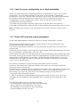
1.4.7 Check CPU load and system parameters
In the web Administration interface open the "system information" window.
This window provides different types of information on the configuration and
peripherals existing on your system.
You must pay particular attention to one parameter in particular, and that is the
system load.
In the first frame located on the top left note the three values appearing on the last
line, For example: system load: 1,80 1,74 1,68.
These figures indicate the average number of processes that require handling by the
processor at any given moment. With the appearance of multicore processors, the
interpretation of this data is not evident. As an initial educated guess, we could
estimate that the figure should not exceed the number of cores (two for a double
core, four for a quad core).
The memory is always occupied at more than 90%, which is normal.
However, the swap (use of the hard disk by the system to overcome insufficient
memory) must be equal to 0.
Another more complete utility is available with versions 5.x.x and earlier of CamTrace
on the console or with ssh access with putty. Connect to the system (quit the
Menucam if you are in it), and at the command prompt (# or $) enter the
command: htop followed by Enter.
A utility in character mode appears that gives the load of each core. You can
configure the information to be displayed. The commands are indicated on the
screen.
The tasks that take up the most resources are:
- Low bandwidth mode (groups with low bandwidth),
- Motion detection performed by CamTrace,
- The indexing of movements in the recordings,
- Camera display on the console
21
1.5 CONFIGURING REMOTE ACCESS
Purpose: To use your CamTrace server from a client station via the Internet or a
private remote link.
We recommend that your local network be permanently connected to the Internet.
Your Internet access provider will give you with a fixed public IP address.
You can also use a dynamic DNS service (to be configured on the router).
1.5.1 Router/firewall configuration
The only IP address that Internet users can reach is the public IP address of your
router provided by your access provider. All requests sent by Internet user browsers to
your CamTrace server will reach the public IP address of your router, which has to
redirect these requests to the CamTrace server.
The router located on the same local network as CamTrace must be configured to
trigger the following incoming routing:
Translation of TCP ports 80, 8000, 8001 and 8002 from the router public IP address
(e.g.: 62.4.20.103) to the CamTrace private IP address on the local network (e.g.:
192.168.1.100).
Refer to the documentation for the router used.
Optional ports to open to manage or monitor the server:
Port 22 (ssh) to access the console with a terminal emulator (putty)
Port 8003 to directly manage certain RAID cards.
Port 8004 to set email alarm transmission via certain RAID cards.
Port 9000 to use the monitoring client: monitor_c in order to monitor the proper
operation of a remote CamTrace server.
22
On the remote surveillance side, if your router (not represented in the schema) has
an integrated firewall, it must be configured to enable the output of the TCP ports
8000, 8001 and 8002. Port 80 is generally open in output.
1.5.2 CamTrace server configuration
The CamTrace server can be reached via the Internet by entering its public IP
address or its full name provided by your access provider.
The 'nslookup' command is used to find the name associated with an IP address or
vice versa. It can be run from most computers connected to the Internet. You can
also contact the technical support of your ISP and ask him the name associated with
your public IP address.
With "Menucam", go to the "Network configuration" menu, then to the "Set host
name, name server, gateway,” and validate.
The "network name" field is the name given to the CamTrace server on the local
network, refer to §1.2.1.
The "Enter the IP Address of the name server: " field is either empty, or filled in with the
IP address of the DNS, internal or external, of the company; refer to section 1.2.1.
In the "Enter the IP address of the gateway" field, enter the private IP address of your
gateway which can be any of the CamTrace networks. In our example, this will be
the private IP address of the router located on the company network, that is:
192.168.1.111
23
1.5.3 Limiting the bandwidth to the outbound gateway
You can limit the bandwidth to the outbound gateway.
In Menucam, go to Network Configuration, then to Network Name, Server Name,
Gateway. Skip the first questions that appear. When you see: Enter the maximum
rate on the gateway in Kbits/s, enter the value selected: for ex. 200 for a limit of 200
Kbits/s on a line with 256 Kbits/s in uplink mode.
This limit is indispensable if you want to use the Internet access for other functions
than video.
1.6 SUPERVISOR CONFIGURATION
A CamTrace Supervisor is a CamTrace server on which you redeclare all cameras
located on a number of remote sites.
The CamTrace Supervisor can group together several hundred cameras that are in
fact physically linked to remote CamTraces.
Take the following configuration as an example:
CamTrace-1 manages 3 cameras: cam1, cam2, cam3
CamTrace-2 manages 5 cameras: cam1, cam2, cam3, cam4, cam5
CamTrace-3 manages 4 cameras: cam1, cam2, cam3, cam4
The three CamTraces below are all connected to an extended (WAN) Internet or
private network. A fourth CamTrace called the supervisor is also connected to the
extended network.
We will declare 12 cameras on the supervisor corresponding to all the cameras
managed by the three remote CamTraces. Video flows will be taken on the three
remote CamTraces (and not on the cameras).
CamTrace-S will therefore manage 12 cameras:
cam1_CT1, cam2_CT1, cam3_CT1,
cam1_CT2, cam2_CT2, cam3_CT2, cam4_CT2, cam5_CT2,
cam1_CT3, cam2_CT3, cam3_CT3, cam4_CT3
With CamTrace Supervisor we can:
- Display any camera via the same interface.
- Make up groups by combining cameras located on a number of remote
CamTraces.
24
- Create maps with
cameras located on a
number of sites.
- Make centralized
recordings, in addition to
those made on each site.
- Quickly check the
operations of all camera
equipment.
- Trigger local alarms via
alarms originating from
remote CamTraces.
- Pilot remote mobile
cameras.
1.6.1 Configuration of remote CamTraces
These configurations are useful if you wish an alarm triggered on a remote CamTrace
to be relayed to the supervisor. For this, you must specify, in each remote CamTrace
(in the example, CamTrace d11 and CamTrace d12), which is the CamTrace
Supervisor and which port is used for alarms.
This configuration is performed
in Manage -> Configuration, in
the section "Event message
parameters” as follows:
In the "messages destination
host name" field, enter the
CamTrace Supervisor IP
address.
25
If the CamTrace Supervisor is located behind a router, you must enter the public IP
address of the router on the WAN side and activate the address translation (NAT) in
the router.
In "target TCP port" type the port used to transmit the alarm signal (by default 8001).
In "message format" enter the following character string: %E%i
Then, if you want the alarm
messages to be sent to the
CamTrace Supervisor, you
must declare an active
calendar (other than
"never") in the "Alarm
Message" field for each
camera concerned.
In our example, the
"entrance" camera will
send TCP alarm messages
to the supervisor when it
has an alarm (irrespective
of the reason for this alarm
– dry contacts – motion
detection in the camera,
motion detection by
CamTrace).
1.6.2 Configuration on the CamTrace Supervisor
The Supervisor CamTrace collects the video flows coming from remote CamTraces.
On the Supervisor CamTrace, you must declare all or part of the cameras connected
to the remote CamTraces.
On the CamTrace Supervisor, these cameras are declared as locally connected in
Manage -> Cameras. It is the camera model that is going to be different. In the list of
camera models (also called camera servers), you must use the model "camtrace".
In the "General" tab
The camera name is user-defined. You should of course give it the same name as the
remote camera ("Entrance" camera in our example) followed by a reference to the
remote CamTrace (Camtrace d11 in our example). Which gives in our example:
Entrance_CT11
26
In "IP Address", select the address of the remote CamTrace on which the camera is
located. If the remote CamTrace is located behind the router, enter the public IP
address of the router on the WAN side.
In the "Acquisition" tab
In "camera type" select: camtrace
Select the PTZ box if the remote camera is mobile.
The parameters: image size,
compression and video
channel cannot be modified
on the Supervisor. If you wish
to modify them you must do
so at the level of the remote
CamTrace to which the
camera is effectively
connected.
In the login and password
fields for the camera’s HTTP
identification, enter the
administration login and
password of the remote
CamTrace (CT11).
In "HTTP port for camera",
enter the video channel used
by CamTrace. By default this is
port 8000.
In the "Extra URL argument"
field, enter the ID of the
camera on the remote
CamTrace according to the
following syntax: id =n (in our
camera, the id of the
"entrance" camera is 1 on the
CamTrace d11 server).
Then enter all the recording and alarm parameters as you would for a normal
camera.
Note: Camera numbers (or ids) represent information internal to CamTrace that appears in
Manage -> Cameras -> Link : "Show details". Each camera has a unique ID number.
It is strongly recommended you check "stop video streams automatically" to
safeguard against saturating the link between CamTraces. When "stop video streams
automatically" is active, the flows from the remote camera are interrupted when no
one is viewing from the Supervisor and when there is no recording.
27
Note: As "stop video streams automatically" is selected, there are no pre-alarm images on the
Supervisor.
In the "if video stream stopped, check the camera every" field, specify the
verification time frame for the camera, for example: 120 for 2 minutes.
Note : In a group or an individual view of the Supervisor CamTrace, the "force recording" key
provokes recording on the Supervisor CamTrace (and not on the remote CamTrace).
1.7 CLUSTER – UNIFIED INTERFACE CONFIGURATION
The cluster option must be activated on all CamTraces from which we want to use a
unified interface. This option is not part of the standard CamTrace license.
In the example above, the cluster option is installed on CamTrace 1 and on
CamTrace 2. All cameras in the cluster can be operated from any client workstation,
which will be connected to CamTrace 1 or to CamTrace 2.
Important: The CamTrace cameras in the cluster (1 to n) are not required to communicate
with each other. They can be on separate networks. Each client workstation establishes the
link with all the servers (1 to n). Servers that are part of the cluster (1 to n) are defined on the
CamTrace equipped with the cluster option (1 and 2). You can install the cluster option on a
single server only (for ex. no. 1); in this case, there will be no backup cluster server in the event
of a connection server failure (no. 1).
The unified interface is used to create and operate single views, cycles, groups,
maps and players (digital video players) whose cameras are attached to any one of
the CamTraces in the cluster (1 to n).
Note: all the CamTrace in the cluster must have the same version.
However, the administrative functions of the cameras, the configuration parameters,
the low bandwidth groups, system logs, viewing of recordings via the database and
the display screens (slave workstations) remain attached to each server.
Each server console keeps its own Menucam.
28
1.7.1.1 Configuration to be performed on all the servers of the cluster
All cluster servers (1 to n) must have the same user name and the same profile names
as those to be used on the CamTraces to which you will connect (no 1 or no 2) to
access the unified interface.
1.7.1.2 Configuration to be performed on client workstations
The client workstations must be able to access all CamTraces in the cluster (1 to n).
On all client workstations, you must therefore add to the trusted sites, all the
CamTraces in the cluster. The client PCs must accept the cookies sent by the cluster
servers.
1.7.1.3 Configuration to be performed on the connection servers
Connect to the administration web interface then
click on servers. The server manager window appears
with contains the list of cluster servers (two in our
example). Click on ‘add a CamTrace server’ to
declare a new server. Leave the server id empty. It will
be allocated automatically. The ports specified are
the default ports.
Note: To make a cluster architecture accessible from the
outside, all the TCP ports of the cluster members must be different and each member of the
cluster must be accessible, from the inside and the outside, with the same network name (use
of a public DNS or modification of host files of client workstations).
Click on Add, then, in the window that appears, reload the main
menu to re-establish the connections with all servers.
The main menu should show a new server (three in our example).
If one or more servers are not active, click on the status line
appearing below the time to obtain a status.
29
Login in red: the user or the profile with which you are
connected to the supervisor does not exist on the
CamTrace server concerned.
Web in red: The Web service of the CamTrace server
concerned is inactive or inaccessible.
Control in red: The video service of the CamTrace server
concerned in inactive or inaccessible.
1.8 DISPLAY SCREENS
1.8.1 Slave screen configuration
To transform a client PC (generally a PC running under Windows) into a display
screen you must launch a display daemon on the PC.
The PC will be "on listening standby" for a CamTrace server, ready to receive display
orders.
Open a browser on the display PC, in the address bar, type:
http://camtrace_url/start.php
For example for the CamTrace server called camtrace14, you would enter
http://camtrace14/start.php if a DNS is active, or, using the example on page19:
192.168.0.100/start.php if the display PC is located on the camera network side or
192.168.1.100/start.php if the display PC is located on the company network side.
If a number of screens are found behind a router you can distinguish between them
by typing: http://camtrace_url/start.php?id=number_of_screen
for example: 192.168.0.11/start.php?id=2
A window appears on the bottom right of the screen.
The last line includes the name of the user of the
screen as it was defined on the server or ??? if it has
not yet been defined.
You can automatically launch the display daemon on startup of the PC by adding it
to the Start menu. To do so, create an IE or Firefox shortcut (as explained in the
"create a desktop shortcut" chapter below).
In the "target" field, type:
"C:\Program Files\Internet Explorer\iexplore.exe" "http://camtrace_url/start.php"
Then place the icon in: Start - programs - Start
To exit the display on the slave station you must kill the session by entering ALT F4.
Note: in a cluster architecture, the screens must be attached to each server. A screen cannot
receive flows from CamTraces to which it is not attached.
30
1.8.2 Pilot display on a slave screen
To start the display, connect to CamTrace from another client workstation.
You must be a CamTrace administrator to define a new screen.
In the web interface, go to admin -> screens.
In Name, enter the name that you want to give to the screen.
In Network Address, enter the IP address of the workstation used as the screen.
In Screen N°, enter 1 by default.
If the screen is a remote screen behind a public IP address, you can differentiate
between screens with their numbers.
In User, choose the user with which you wish to associate this screen from a rights
point of view. You can only display cameras visible with the profile of the chosen
user.
You can choose an individual camera or a group.
If the Keep Proportions box is not selected, display takes place in full screen mode,
and the image may be deformed. If it is checked, display is in maximum size mode,
which retains the image proportions.
To stop display from a client workstation as an administrator, you must remove the
user name (blank choice) in User.
It is also possible for a CamTrace user who is not an administrator to manage the
screens from a map (View - Maps). For this, the user profile must enable assignment
of these screens. In ‘Admin – Profiles’ open the desired profile. Open the "screen
assignation permissions" tab and select the boxes corresponding to the screens that
the users associated with this profile can manage from a map.
1.8.3 Case with a slave multiscreen workstation
Certain video cards can be used to pilot a number of screens. In this case, you can
launch more than one slave CamTrace on the same workstation, distinguishing
between them with their ID number. To do this, type:
192.168.0.11/start.php?id=1 in the browser address bar, then open a new browser
and type: 192.168.0.11/start.php?id=2 in its address bar.
To position each of the CamTrace windows in a group of screens you must provide,
as an argument for each CamTrace slave program, the margin in pixels between
the upper left position of the Window and the upper left position of the group of
screens.
In the schematic example below, if each of the screens has a
resolution of 1280 x 1024, to display on screen B you must
type: 192.168.0.11/start.php?id=1&left=1280
To display simultaneously on screen D you must enter:
192.168.0.11/start.php?id=2&left=1280&top=1024
left is the left margin between the left side of the CamTrace
window and the left side of the group of screens.
top is the top margin between the upper side of the CamTrace window and the
upper side of the group of screens.
Attention: The multi-screen video controller must be configured in such a way that the full
screen function is managed separately on each screen.
31
1.9 MANAGEMENT OF CAMERA OPTIONS
Certain cameras have additional functions such as output contacts, LEDS, sound
alarms, etc. that can be piloted via the network using the options mechanism.
CamTrace can be used to activate the functions of these cameras in their individual
display window or in a group. When the option is defined it appears in a display in
the camera’s context-sensitive menu (right-click in the image) in the "options" submenu with a title defined by you.
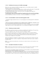
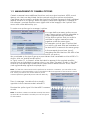
To enter new options go to manage / options
You can define as many options as you
want. These options must be attached to
a type (represented by a number).
Group all the options that you want to
activate in a given camera model
together under the same type.
For example, put all type 2 options that
you wish to use and that are available on
an Axis M1031 camera in the same group.
In the example shown here, type 2
describes the URLs that turn the LEDs of an
M1031 off and on.
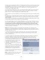
We could add to the type 2 group a sound alarm that is available on the M1031s. To
do this, click on "Add a model option"
In "Type": enter "2". In "Name": enter the label to appear in the context-sensitive
menus from an individual or a group view. In our case: "fire alert". Finally, in the "URL"
enter the command that will be used to execute the desired action. In our case:
/axis-cgi/mediaclip.cgi?action=play& clip=1
Note : To find the commands used to perform an action in a camera, you can refer to the
manufacturer’s documentation or try to locate the URL that appears in the browser’s status
bar when you launch the action directly in the
camera (Firefox is generally more verbose than I.E.).
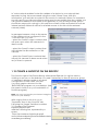
Then, in Manage / Models click on Modify
opposite to the camera model: axism3011.
Declare the option type 2 for the M3011 camera
model.
Note: If another camera model has exactly the same
options URLs as the M3011 model you can use type 2
for this model.
32
1.10 POSITIONS AND PATROLS OF MOTORIZED CAMERAS
Mobile cameras have predefined positions (presets) and some have rounds (patrol)
function internal to the camera.
You must first declare the presets in the camera itself and then define the
sequencing of these positions. Refer to the documentation for each camera model
to perform these declarations, and then check that the presets and the patrols
function correctly with the native interface of the camera.
When declaring a PTZ camera in administration / cameras, a "synchronization" key
enables CamTrace to acquire predefined positions and rounds for the camera.
During display, users with PTZ rights (Pan Tilt Zoom) can use the presets and the rounds
with a right-click in the image or by clicking on PTZ at the top of the image.
1.11 INSTALL THE CAMIO MODULE INPUTS/OUTPUTS
This module is optional. It is not delivered with the standard CamTrace package.
There are two models including either two or eight inputs and outputs.
The CamIO module enables you to pilot 2 inputs and 2 outputs or 8 inputs, and 8
outputs including a watchdog with your CamTrace server. The inputs are used to
trigger CamTrace alarms per camera group. The outputs are used to notify the
absence of a router, a default in one camera in a group or a fault in the CamTrace
video service.
To function, the CamIO module must be connected to a power supply and to one of
the serial ports on your CamTrace server.
The serial cable must be straight (end to end) with all wires cabled. It is a simple
extension cord.
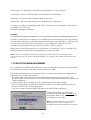
To declare and test the CamIO housing, start the
Menucam on the system console or from a client
workstation with putty.
Go to "System configuration" then to "CamIO
Module ". The following screen appears:
If you start the module detection you obtain the following type of message:
33
The inputs are numbered from E0 to E7 or E0 and E1 (on the box with two paths). They
are triggered by dry contacts. To test the E0 input, you can short circuit the two E0
terminals, to test the E1 input, the two E1 terminals, etc. The two terminals for a
contact are located side by side.
The outputs are numbered from S0 to S6 and WD or S0 and WD. They are piloted by
micro-relays (Max 1 A) and can be used to open or close dry contacts or power
relays. The two contact terminals are located side by side.
If the CamIO box is not powered on or if CamTrace is shut down, the contacts are all
open.
The launching of CamTrace video services closes all the contacts. When CamTrace is
operating with its video services active its contacts are normally closed. They open
upon an alarm.
If the CamTrace video services are stopped, the contacts (except WD) remain in the
state that they were in (if the CamIO box is still powered).
The WD (WatchDog) contact operates differently from the others. To remain closed,
this contact must receive, in a timeframe less than a specified value (for eg: 15 sec.)
a closing order sent by the CamTrace video program. If for any reason the video
program does not send it this order within the required time limit, then the contact
opens automatically. The opening of this contact therefore indicates a lack of video,
whether software or hardware.
Note: Before testing the module, be sure that it is NOT activated in the CamTrace web
interface. Go to the Administration / Configuration / Tab "Contact box parameters". Set to
the serial port for the contact box to "None", without forgetting to restart the video service for
this to be taken into account.
To test the inputs start "input test" in Menucam then, short circuit successively the
inputs (for example with a paper clip). Their state should change on the screen.
n° input : state (0 or 1)
To test the outputs you need a device that reacts when the contact is closed. For
example, a battery in series with a small low voltage bulb: Start "Output test" in
Menucam. The test procedure opens and closes all the contacts successively.
Corresponding messages appear on the screen.
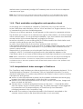
To activate the CamIO module in the
CamTrace web interface, go to
"manage" / "configuration". Click at the
top on "modify".
Open the "contact box parameters" tab.
Choose the COM port to which the box is
plugged (this is the COM port that is
specified after a "module detection").
Choose the Watchdog timeout delay (in
practice 15 seconds)
Note: To check if the WD stops at the end of
the specified time, shut down the video
service with Menucam.
34
In "router network address" enter the address of a device in your network that
responds to ping. We recommend using the router if there is one. With this
mechanism, you activate a contact in the event of a network failure. For increased
security and if your video surveillance setup must be accessible from the outside, you
can give the address or the name of the gateway of your access provider (which
should also respond to a ping). In this case the contact will be activated for both an
internal network failure as well as for a failed access to the site via the external
network (WAN).
In manage/cameras, click on the name
of the camera to be configured, in the
"Contacts" tab, you can:
- select the CamIO output contacts that
will open upon when this camera is in
alarm mode.
- select the CamIO output contact that
will indicate the disconnection of this
camera.
- select the CamIO input contacts that,
will put this camera in alarm mode when
any of them is opened.
1.12 CREATE A SHORTCUT ON THE DESKTOP
This function opens CamTrace directly with Internet Explorer for a given user by
clicking on an icon on the desktop. It is used if necessary to directly access a group
of cameras in display mode or any desk
configuration via the "desk" function.
You must create a shortcut for the
'IEXPLORE.EXE' program on your desktop. (Use
the search function on your workstation to
find this program.)
Note: You must not create your shortcut using the
IE icon on your desktop.
With a right click on the icon, go to
"Properties" then in the "shortcut" tab
Following the "target" field that contains:
"C:\Program Files\Internet
Explorer\iexplore.exe"
add the following line, separated by a
space:
"http://ipcamtrace/login/login.php?
user=username&pass=password&desk=deskn
ame&lang=codelang"
35
ipcamtrace = IP address or CamTrace server name on your network
username = name of the user previously declared in CamTrace
password = the password corresponding to this user
deskname = name of the desk previously defined in CamTrace
codelang = code for language used (de for Germany, en for English, fr for French, it
for Italian, nl for Deutch).
Browser language by default.
Example:
"C:\Program Files\Internet Explorer\IEXPLORE.EXE" "http://carnac/login/login.php?user=john&pass=Ke27diZ&desk=labs&lang=en"
Create a CamTrace icon (eye) on your desktop by downloading it from CamTrace.
Via the main CamTrace menu (browser banner) go to the help then in "utilities" right
click on the CamTrace logo. Then click on "save target as" and save the file
containing the (camtrace.ico) icon in a location of your choice.
Right-click on the IE shortcut icon to CamTrace. In "Properties", go to "change icon"
and provide the CamTrace icon path that you want to save.
Note : when you create a desktop (in display/icon located in the bottom right of the
CamTrace banner), be sure to arrange windows so that they are wholly contained in the
screen.
1.13 MULTIVOLUME MANAGEMENT
As of CamTrace versions 4.8.x and later, you can manage a number of logical disks.
The interface is used to allocate each camera to a disk.
There are several items of information that you must have at hand to organize the
hardware for a CamTrace system.
- The system disk (that which hosts the operating system) cannot exceed 2 TB.
- The other disks use the UFS file system and have a theoretical maximum capacity of
1 billion terabytes.
- A logical disk can be made up of a number of physical disks in RAID.
- A PC motherboard has a limited number of SATA connectors and BIOS limits the
number of disks that can be declared.
- You can connect external RAID disk bays with SAS or fiber interfaces.
"Declared spaces", specifies the
number of logical disks in addition to
the system disk. In our example, there
are therefore two disks.
Note : During installation of CamTrace
software via a CD or a USB key, the
installation procedure detects the present
36
disks. You must designate the disks that will be used by CamTrace and from among these, the
system disk.
To delete a disk, all camera recordings allocated to this disk must be erased.
The migration of recordings from one disk to another takes place with the video
system shut down. This function is available
with versions x.9.5 and later.
During declaration of a new camera, you
should specify on which disk it will be
registered. This assignment of a camera to
a hard drive can be done either in the
web interface, manage/camera in the
"Records" tab, (as shown here).
Or in Menucam, in "camera configuration"
then "detect and add new cameras".
With Menucam, you can detect and add
(or not) all the cameras present on the
network.
Detection can take a few moments.
Certain camera models cannot be detected.
In the column to the left, Menucam suggests by default the disk with the most
capacity.
You can choose to allocate a
camera to another disk by
following the instructions in the
menu.
If the column to the left contains
an empty field, the camera will
not be added.
Attention: When you declare a new
camera, allocate its disk before starting the recordings. Otherwise, you will need to erase the
recordings before re-allocating the camera to another disk.
1.14 GRAPHIC MODE ON THE CONSOLE
Startup and shutdown
You can start up graphic mode on the CamTrace console.
In Menucam, go to "graphical mode on console".
37
Before starting graphic mode with option 1, be sure to set up the screen type. The
screen parameters are specified above the menu. When you are in the option
"Change the screen type", "Accept" trigger a state change from TFT (flat screen) to
CRT (cathode screen).
Set the resolution for your screen between VGA, SVGA and XGA.
Start graphic mode in Menucam. Graphic mode starts up in a new console.
To log on in graphic mode the user is: "camtrace". The default password is: "camera".
To return to the console in character mode type: CTRL ALT F1
To access the console in graphic mode when it is launched, type:
CTRL ALT F9
To quit graphic mode use Menucam or type: CTR ALT ← (backspace)
Graphic applications
The graphical interface offers a certain number of applications:
Files: file explorer
Firefox: browser
Terminal: terminal emulator.
You can start Menucam in this
emulator.
Camtrace: video application
Slave screen: Launches a passive
screen to pilot display on the console
from another client workstation.
User's manual: A pdf reader enables you to read online manuals.
Execute: to type and launch a shell command.
Other parameters in the graphic interface in Menucam
38
The "start automatic login" field is used to start a graphical session during startup or
restartup of CamTrace. The session is started for the "camtrace" user.
"Change the startup command" give access to the "Graphic mode startup"
submenu.
This menu is used to specify
the mode in which the
CamTrace client will be
automatically launched on
the console during a
CamTrace restart.
Automatic login must be
activated.
"Start with the monitor group" launches the group called "monitor" (or "moniteur"). A
group with the same name must have been previously created with the web
interface. This mode is recommended when you wish to display a group permanently
on the console.
"Start in passive screen mode" launches passive screen mode on the CamTrace
startup console. Graphical mode and automatic login must be activated. This mode
is used when you want to be able to change the display on the console from
another client workstation.
"Start with a user desktop" specifies a desktop (recall of several windows: individual
views, cycle, groups or plans) recorded beforehand.
Note: To save a desktop containing a full screen press ALT TAB to redisplay the main
CamTrace banner.
"Customize startup command" launches a command that will be automatically
executed after startup in graphical mode.
The command must end with an & (execution in background mode) and can start
with: nice -n x (with x between 1 and 10) to lower its priority (10 is the lowest).
Attention: the permanent display of images on the console consumes considerable
processing resources. For a group display, you should limit the number of images per second.
We do not recommend permanent display of images on the console for large installations
(CamTrace server).
Important: you cannot display mpeg4 or H264 flows on the console. Only Mjpeg flows can be
decompressed and displayed on the console.
39
40