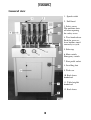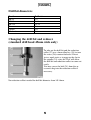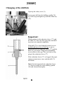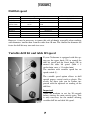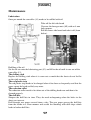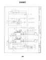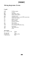
1
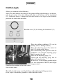
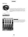
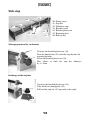
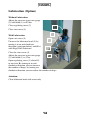
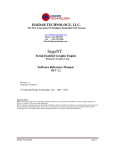
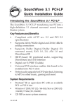
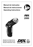
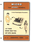
CITOBORMA 490
User manual
English
Contents
Contents .........................................................................................................................2
General view ..................................................................................................................3
Safety and cautionary notes...........................................................................................4
Setting up .......................................................................................................................4
Sense of rotation of the drill bit motor ..........................................................................4
Drill bit diameters ..........................................................................................................5
Changing the drill bit and reducer (standard drill head 45mm wide only)...................5
Changing of the drill bits...............................................................................................6
Drill bit speed ................................................................................................................7
Variable drill bit and table lift speed.............................................................................7
Moving sideways a head................................................................................................8
Removing a head ...........................................................................................................8
Adding a head ................................................................................................................9
Drill bit depth...............................................................................................................10
Depth adjustment .........................................................................................................11
Back fence....................................................................................................................12
Side stop.......................................................................................................................13
Lubrication (Option)....................................................................................................14
Drilling.........................................................................................................................15
Recommended options.................................................................................................16
Maintenance.................................................................................................................17
Faults............................................................................................................................18
Technical data ..............................................................................................................18
Wiring diagramm (Basis) ............................................................................................20
Wiring diagramm (Vario) ............................................................................................22
Declaration of conformity ...........................................................................................23
2
General view
1. Speed switch
2. Drill head
3. Safety cover
The machine shuts
off when opening
the safety cover.
4. Two-hand release
Push the green release buttons simultaneously to cycle.
5. Side stop
6. Main switch
Emergency switch
7. Foot pedal socket
8. Levelling foot
9. Tool case
10. Back fence
handwheel
11. Table heighth
handwheel
12. Back fence
3
Safety and cautionary notes
Use original Nagel parts only for any repairs.
Unplug the power cord for any repairs.
Repairs and any other work on the drill should only be carried out by an approved
service engineer.
Safety devices must not be taken off or disabled. Never operate the machine when
damaged (damaged power cord etc.).
Drill paper and cardboard only.
Never reach into the working area when the table or drill bits are moving.
Install the power cord out of the way to avoid tripping over it.
Work place of the operator: in front of the machine.
Install the machine in a dry work shop.
Setting up
Set up machine on a firm, level surface facing the operator and plug in the mains
plug.
Put the drill in place and level it with the levelling foot (8).
Sense of rotation of the drill bit motor
Check the sense of rotation of the drill bit motor before starting to work for the first
time. If the drill bits turn opposite to the direction indicated by the arrow then switch
the position of any two out of the three current wires in the three phase plug of the
machine. But never touch the neutral wire (marked „N“) or the earth wire (yellowgreen).
4
Drill bit diameters
Head
BK 32
BK 45
BK 125
Trio
Filofax
Filofax 6
Drill- / mm
2-9
2-14
15-35
2-6
2-6
2-6
Changing the drill bit and reducer
(standard drill head 45mm wide only)
To take out the drill bit and the reduction
collet (27) use a 4mm allen key (24) to turn
the screw (26) counterclockwise. Excert
just as much twist as to open up the slot in
the spindle (25) a tiny bit. This will allow
the drill bit and reduction collet to come out
easily.
You may screw the bolt (28) from the accessories bag into the reduction collet if
necessary.
No reduction collect needed for drill bit diametes from 10-14mm.
5
Changing of the drill bits
Open up the safety cover (3).
Insert paper drill into the drilling spindle (76)
up to the stop and tighten up with the Allan key
(24).
Important:
When pushing-in the reduction sleeve (77) and
the drill (78), take care that paper dust and drilling waste are removed completely.
If the drill (78) is not clamped correctly or not
pushed right up as far as it will go, a gap remains between the reduction sleeve (77) and the
drill (78) (see arrow). Paper dust and drilling
waste collect in this gap. This can lead to clogging of the reduction sleeve (77).
If the reduction sleeve (77) is clogged, the paper
cuttings cannot move away and the drill (78)
will break.
When this has happened, the reduction sleeve
(77) must be taken out of the drilling spindle
(76) and cleaned thoroughly.
6
Drill bit speed
Head
Head 32
Head 45
Head 125
Drill-& / mm
Trio
Filofax
Filofax 6
Speed switch (1)
Position 1= 1890 1/min
N/A
(Position 2= 950 1/min) Position 2= 1890 1/min
Position 1= 550 1/min
Position 2 = 1100 1/min
21-35
15-20
Position 2
Position 2
Position 2
Vario Poti (29) Min-Max
1510-(3436)
755-1718
550-1260
However, it may be necessary to ignore this rule of thumb, especially when working
with diameters smaller than 4 mm or wider than 10 mm. The smaller the diameter the
faster the drill bit may turn and vice versa.
Variable drill bit and table lift speed
If your Citoborma is equipped with this option use the upper knob (29) to control the
drill bit speed and the lower knob (30) to
control the table lift speed. (Min = 8
strokes/min, max. = 19 strokes/min)
The machine with variable speed has no
speed switch (1).
The variable speed option allows to drill
special papers, coated stock or plastic. The
results for these jobs can be further improved with the optional air cooling of the
drill bits.
Important!
Allow the machine to rest for 30 seconds
before starting the main switch again. This
is only necessary for the models offering
variable drill bit and table lift speed.
7
Moving sideways a head
Loosen the fixing screw (41) lightly to move the head sideways. The scale above the
heads helps finding the desired position. The zero indicates the centre of the machine.
Removing a head
Turn off the main switch.
Open the screw (31) the small cover plate
(33).
Take out the fixing screw (32) with a 4 mm
allen key.
Pull out the splined shaft (34) as far as needed. Screw the grip from the accessories
bag (35) onto the shaft to pull the shaft out
easily.
Pull off the air cooling tube from the distributing block by pressing the blue ring.
The black pins (enclosed with the accessories) can be placed upon the distribution
block instead of the air cooling tube (this can only be done when having a machine
which is established with the air cooling system).
Turn the fixing screw (41) completely up and take the head out towards yourself.
8
Adding a head
Turn the fixing screw (41) completely up.
Lift the head onto the support bar taking care that it rests well against the support
bar. The right picture shows an incorrectly inserted head.
Tighten the fixing screw firmly.
Play with the splined shaft by turning it when pushing it back through the heads in
case the gear taking up the shaft has lost the correct position.
Do not forget putting back in the fixing screw (32) onto the shaft with a 4 mm allen
key.
correct
incorrect
9
Drill bit depth
Always pay attention to the following.
After every drill change and whenever the proper drilling depth setting is not known,
take the precaution to turn the drilling table right to the bottom with the handwheel
(11). Otherwise there is a danger that the table stroke is too large so that the drills
penetrate the work table and break.
Knurled screw (39) for locking the handwheel (11).
Place the drilling cardboard (79) on the
drilling table as drilling underlay.
Place the adjusting gauge (78) under the
drill (23) which stands lowest.
Move the drilling table upwards with the
handwheel (11) until the adjusting gauge
lightly contacts the drill.
Take out the adjusting gauge (78).
Check with the adjusting gauge that no
other drill stands lower.
If necessary, set the drilling spindle higher
(see user instructions CB 490 „drill length
compensation“).
Switch-on the machine at the main switch.
Start a work stroke.
The drills should clearly mark the drilling cardboard during drilling operation.
If not, adjust at the drilling spindles or adjust the table stroke.
10
Depth adjustment
Head BK 45
Pull down the locking bolt (42) and turn
the knurled screw (40). The max. adjustment is 4 mm.
11
Back fence
Use the handwheel (40) to change the back fence position.
The handwheel can be locked with the fixing screw (45)
below the handwheel. The sunk-in scale in the table indicates the distance between the drill bits centres’ and the
back fence.
Important!
The four stops (47) of the back fence must
always be positioned between and out of
the way of the heads (2). Move the stops
sideways if necessary (10 mm spanner).
12
Side stop
53
50
52
51
55
56
54
50. Fixing screw
51. Stop bar
52. Tabulator stops
53. Knurled screw
54. Knurled plastic nut
55. Retaining plate
56. Release key
Managing incorrectly cut formats
53
54
Unscrew the knurled plastic nut (54).
Turn the knurled nut (53) until the stop bar has the
required position.
Fasten the knurled plastic nut (54).
This allows to shift the stop bar sideways
by +/- 3mm.
Exchange of the stop bar
51
54
Unscrew the knurled plastic nut (54).
Take off the retaining plate (55).
Pull out the stop bar (51) upwards to the right.
55
13
Lubrication (Option)
Without Lubrication:
Adjust the pressure at pressure gauge
(2) with knob (1) to 0,5 bar
Close regulating screw (3)
1
Close vent screw (4)
2
With Lubrication:
Open vent screw (4)
Unscrew the lubricator bowl (5) by
turning it in an anti-clockwise
direction (seen from below) and fill it
with Nagel Drill Lubricant.
3
4
Close the vent screw (4)
5
Adjust the pressure at pressure gauge
(2) with knob (1) to 3 bar
Open regulating screw (3) about 0,5
to one turn. By turning in an anticlockwise direction you can increase
the number of drops, by turning in a
clockwise direction you can reduce the number of drops
Attention:
Clean lubricator bowl with water only
14
Drilling
Switch on the main switch.
Knock up the pile of paper and push it firmly against the side stop and back fence.
Push the green buttons of the two hand release simultaneously.
The table now travels upwards.
Keep pushing the buttons until the table has reached the upmost position.
Otherwise the table will reverse immediately for your security.
15
Recommended options
Standard head 445
Distance between centres: min. 45 mm
Drill bits: 2 - 14 mm
Special head 432
Distance between centres: min. 32 mm
Drill bits: 2 - 9 mm
Special head 4125
Distance between centres: min. 125 mm
Drill bits: 15 - 35 mm
Special Filofax head with three spindles
Distance between centres: 19 mm
Drill bits: 2 - 6 mm
Special Trio head with two spindles
Distance between centres: 21 mm
Drill bits: 2 - 6 mm
Nagel drill bits, diameters 2 - 35 mm, various lenghts, various qualities.
Drilling cardboard
Drilling stick
Wax paper
Drill sharpener with honing stone
Additional tabulator stop
Additional stop bar
Stop bar manufactured upon your individual specification
Foot pedal
Air cooling for the drill bits: This option
reduces the wear of the drill bits.
To drill plastic, coated stock and special
papers: The „Citoborma 490 Vario“ with
variable drill bit and table lift speed. This
option cannot be installed posterior.
16
Maintenance
Lubrication
Once per month the cam roller (81) needs to be refilled with oil.
Take off the left side board
Unscrew the hexagon nuts (80) with an 8 mm
fork-spanner.
Pull the lower side board and take it off (from
below).
Refilling of the oil
Set the oil can onto the lubricating port (83) and fill in the oil until it runs out of the
cam roller (81).
The drilling stick
Replace the drilling stick when it is worn out so much that the sheets do not lie flat
on the stick anymore.
The red plastic strip
The red plastic strip needs to be changed when it has been so frequently used that the
paper cannot be layed on flatly any more.
The reduction collet
The reduction collet needs to be taken out of the drilling head now and then to be
cleaned properly.
The drill bits
Sharpen the drill bits in time. They do need resharpening when the holes in the
sheets are torn out.
Drill through wax paper serveral times a day. The wax paper greases the drill bits
from the inside in a clean manner and avoids the blocking with drill chips which
leads to broken drill bits.
17
Faults
Fault
Machine not running:
Ragged holes:
Drills block,
drills squeak:
Bottom sheets not perforated:
Remedy
Plug in mains plug,
switch on main switch
Replace blunt drill,
replace drilling base
Perforate waxed paper
Adjust drilling depth downwards
If faults are not eliminated by these instructions, please contact your Nagel dealer.
Technical data
Noise emission:
< 70 dB (A)
Power supply:
see rating plate
Drill diameter:
2 - 35 mm
Max. pile depth: 60 mm
18
19
Wiring diagramm (Basis)
Legend
BM
BO
BS
HM
MV
PE
Q1
S1
S2
S3
S6
ST
VK
VO
ZR
ZU
Drilling engine
Drilling
Operating voltage
Piston stroke engine
Solenoid valve
System-unit covers and all PE connections
Main ticket offices
Bonnet contact
Foot switches
Position switches
Pole shifters
Gate current part
Pre-securing of Kundenseitig
In front of
Two hand relays
Back
Wirecolour
L1, . . L3, U, V, W
Zero pus; N
Ground; PE
Controlcircuit
Black
Blue
green-yellow
Red
20
21
Wiring diagramm (Vario)
Legend
BM
BO
BS
HM
MV
PE
Q1
S1
S2
S3
S6
ST
VK
VO
ZR
ZU
Drilling engine
Drilling
Operating voltage
Piston stroke engine
Solenoid valve
System-unit covers and all PE connections
Main ticket offices
Bonnet contact
Foot switches
Position switches
Pole shifters
Gate current part
Pre-securing of Kundenseitig
In front of
Two hand relays
Back
Wirecolour
L1, . . L3, U, V, W
Zero pus; N
Ground; PE
Controlcircuit
Black
Blue
green-yellow
Red
22
Declaration of conformity
The conformity with all EC regulations and also the german GS regulations has been
officially controlled by the following authority: Fachausschuß Druck und Papier der
Berufsgenossenschaft. The machine complies with the rules 89/392 and 89/336 of
the European Community.
Additional rules: EN 954-1, prEN 1010, EN 60204.
Michael Kipp
Geschäftsführer
CITOMORMA 490
SN:> 980761
23
Ernst Nagel GmbH
D – 70565 Stuttgart, Germany
Inland
0711 78078 11
Export
+49711 78078 21
Telefax
+49711 78078 10
www.ernstnagel.com