1
g
GE Consumer & Industrial
Digital Energy™
SNMP/Web Interface
USER MANUAL
Digital Energy
TM
SNMP/Web Interface
g
Telephone
+41 (0) 91/850 51 51
GE Digital Energy™
6595 Riazzino (Locarno)
Fax
+41 (0) 91/850 51 44
General Electric Company
Switzerland
Website
www.gedigitalenergy.com
g
GE Consumer & Industrial
Digital Energy™
SNMP/web Interface
GE imagination at work
V070 GB
g
Digital Energy™
Model:
SNMP/Web Interface card
SNMP/Web Interface box
Date of issue:
17.09.2004
File name:
OPM_CON_SNM_BAS_CRD_XGB_V070
Revision:
1.0
1009224
1009223
Identification No.
Up-dating
Revision
Concerns
Date
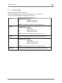
7.0
New template
Implementation of the new functions
- NTP client
- syslog
30.05.2004
Please read these instructions carefully before installation and use of the SNMP/WEB Interface.
We recommend you keep this manual in a safe place for future reference.
© 2004 by GE Industrial Systems
All rights reserved.
The information contained in this publication is intended solely for the purposes indicated.
The present publication and any other documentation supplied with the UPS system is not to be reproduced, either in part or in its entirety,
without the prior written consent of GE.
OPM_CON_SNM_BAS_CRD_XGB_V070.doc
3/37
User Manual SNMP/Web Interface
g
Digital Energy™
The illustrations and plans describing the equipment are intended as general reference only and are not necessarily complete in every
detail.
The contents of this publication may be subject to modification without prior notice.
OPM_CON_SNM_BAS_CRD_XGB_V070.doc
4/37
User Manual SNMP/Web Interface
g
Digital Energy™
Contents
1
2
3
4
5
6
7
8
9
10
11
Introduction ........................................................................................................................7
1.1 Introduction.................................................................................................................9
1.2 SNMP Agent...............................................................................................................9
1.3 Web Server ................................................................................................................9
1.4 Telnet .........................................................................................................................9
1.5 Email ..........................................................................................................................9
Installation ........................................................................................................................10
2.1 CARD version...........................................................................................................10
LED status ........................................................................................................................12
3.1 Card..........................................................................................................................12
Configuration methods ...................................................................................................14
4.1 Configuration over the network ................................................................................14
4.2 Configuration via a serial connection .......................................................................14
4.3 Introduction...............................................................................................................14
Configuration by a telnet / RS232 connection ..............................................................15
5.1 Communication possibilities.....................................................................................15
5.2 Logon .......................................................................................................................15
5.3 Save the settings......................................................................................................15
5.4 General commands..................................................................................................16
5.5 Network settings.......................................................................................................17
5.6 DNS settings ............................................................................................................18
5.7 User..........................................................................................................................19
5.8 Service settings ........................................................................................................20
5.9 Email settings (SMTP) .............................................................................................21
5.10 SNMP ......................................................................................................................22
5.11 SNMP Trap..............................................................................................................23
5.12 UPS information ......................................................................................................23
5.13 UPS settings ............................................................................................................24
Web Interface ...................................................................................................................25
6.1 Overview ..................................................................................................................25
6.2 Network settings.......................................................................................................25
6.3 User settings ............................................................................................................26
6.4 Service settings ........................................................................................................26
6.5 DNS test ...................................................................................................................27
6.6 Speed/duplex configuration......................................................................................27
6.7 SNMP configuration .................................................................................................28
6.8 SNMP trap configuration ..........................................................................................28
6.9 Email configuration...................................................................................................29
6.10 UPS Identification ....................................................................................................29
6.11 UPS Status ..............................................................................................................30
6.12 UPS Alarms .............................................................................................................30
6.13 UPS test...................................................................................................................31
6.14 UPS configuration....................................................................................................31
6.15 Save settings ...........................................................................................................32
6.16 Reboot settings........................................................................................................32
USE....................................................................................................................................33
7.1 SNMP Agent.............................................................................................................33
7.2 Web Server ..............................................................................................................33
Firmware upgrade............................................................................................................34
8.1 Firmware upload.......................................................................................................34
8.2 Firmware upgrade ....................................................................................................34
Subnet-mask calculation ................................................................................................35
Supported MIB Variables ................................................................................................36
Support .............................................................................................................................37
11.1 First line support ......................................................................................................37
11.2 Internet Support .......................................................................................................37
11.3 Web Server Support ................................................................................................37
OPM_CON_SNM_BAS_CRD_XGB_V070.doc
5/37
User Manual SNMP/Web Interface
g
Digital Energy™
OPM_CON_SNM_BAS_CRD_XGB_V070.doc
6/37
User Manual SNMP/Web Interface
g
Digital Energy™
1 Safety rules
With this document, GE gives to the user all the necessary information about the correct
installation and connection with the UPS units.
Please carefully read this Installation Guide before installing or operating the equipment.
If any problems are encountered with the procedures contained in this Installation Guide,
please contact the nearest Service Centre before you proceed.
All UPS installation, maintenance and service work should be performed by qualified
service personnel only.
KNOWLEDGE and FULL compliance of the safety instructions and the warnings
contained in this manual are
THE ONLY CONDITION
to avoid any dangerous situations during installation, operation, maintenance
work, and to preserve the maximum reliability of the UPS system.
NOTE !
The installation and cabling of the option “RPA KIT” must be
performed by QUALIFIED SERVICE PERSON.
Please refer to the “Safety Rules” included in the “Operating
Manual” of the UPS.
Please read carefully the UPS “Operating Manual & installation
Guide” before installing or operating the equipment.
If any problems are encountered with the description of this
installation guide, please contact the nearest Service Centre before
proceeding.
Please for the installation and cabling of the RPA KIT in USA use
only type DP (DP1, DP1-P or DP2, DP2-P) or equivalent cable.
GE
refuses any responsibility in case of nonobservance, unauthorised alterations or improper
use of the delivered equipment.
OPM_CON_SNM_BAS_CRD_XGB_V070.doc
7/37
User Manual SNMP/Web Interface
g
Digital Energy™
2 Content of the kit
Content of the SNMP / Web Interface card
User manual
SNMP / Web Interface card
Content of the SNMP / Web Interface box
User manual
SNMP / Web Interface box
Power supply
Serial cable (1:1)
OPM_CON_SNM_BAS_CRD_XGB_V070.doc
8/37
User Manual SNMP/Web Interface
g
Digital Energy™
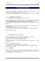
3 Introduction
3.1
Introduction
The SNMP/Web Interface is designed to present UPS information on the network.
The interface is available as a plug-in card and also as an external box.
Both products are identical, except that the external box additionally supports Contact Interface
communication.
The interface provides the UPS information in different ways:
3.2
SNMP Agent
The SNMP information complies with the standard UPS-MIB, which is defined in RFC1628.
This format allows one or more NMSs (Network Management System) to monitor, manage and
control the UPS.
In addition, General Electric Digital Energy network enabled protection software (PowerJUMP
DataShield) can use this information to determine the status of the UPS in order to guarantee safe
and orderly shutdown when needed.
3.3
Web Server
The UPS information is also available in HTML format. HTML is the basic language for Internet
communication. Any standard internet browser can be used to monitor and control the UPS using
HTML from anywhere on the network or even from anywhere in the world when using the internet.
For more information about SNMP/Web Interface card please consult the software support pages on
the General Electric DE website: www.gedigitalenergy.com.
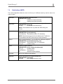
3.4
Telnet
For a simple way to see the UPS values you can use the telnet connection. This can be useful
where no web browser is available.
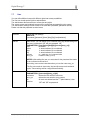
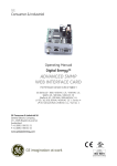
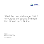
ARCHITECTURE DIAGRAM
Windows
RS232 UPS
Linux
UNIX
Ethernet
UTP
Comport PC
(console)
1:1 RS232
3.5
NOTE:
only required for
configuration
Email
Up to 8 different users can be informed by email in case of an event or alarm.
OPM_CON_SNM_BAS_CRD_XGB_V070.doc
9/37
User Manual SNMP/Web Interface
g
Digital Energy™
4 Installation
4.1
Card version
1.
Switch off the UPS, and wait approx. 2 minutes or switch the UPS to the manual bypass.
Please ensure that the mains input is reliable during this period.
2.
Install the SNMP/WEB Interface card in the RS232 option slot. For more details about the slot
please read the UPS user manual.
3.
Make all necessary connections (see architecture diagram in chapter 1).
4.
Switch on the UPS or go back to normal mode from bypass.
OPM_CON_SNM_BAS_CRD_XGB_V070.doc
10/37
User Manual SNMP/Web Interface
g
Digital Energy™
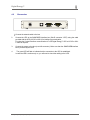
4.2
2
Box version
1. Connect the network cable to the box
2.
Connect the UPS to the SNMP/WEB Interface box (Sub-D connector “UPS”) using the cable
provided with the UPS (VIC/23 or IMV-I) for intelligent communication.
For using the Contact Interface communication to a GE Digital Energy™ UPS a VIC-25 or IMVC cable is required.
3.
Connect the power to the box (most left connector). Make sure that the SNMP/WEB Interface
box is powered by the UPS!
4.
The green LED will flash to indicate that the connection to the UPS is established.
In case the LED is continuously on, you will need to check the cabling to the UPS.
OPM_CON_SNM_BAS_CRD_XGB_V070.doc
11/37
User Manual SNMP/Web Interface
g
Digital Energy™
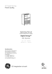
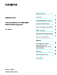
5 LED status
5.1
Card version
Ethernet (RJ45)
2nd LED
3rd LED
Network LED
RS232
Reset button
Network LED
Off
No LAN connection
Solid green
LAN connection established, no communication on the network
Flashing green
LAN connection established, receiving or transmitting data packets
2nd LED
This LED has no function.
3rd LED
This LED has no function. It flashes continuously.
OPM_CON_SNM_BAS_CRD_XGB_V070.doc
12/37
User Manual SNMP/Web Interface
g
Digital Energy™
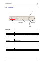
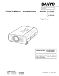
5.2
Box version
Network LED
reset
Net link
Fault
Active
Reset button
Fault LED
Active
Network LED
Off
No LAN connection
Solid green
LAN connection established, no communication on the network
Flashing green
LAN connection established, receiving or transmitting data packets
Fault LED
Off
No fault
Solid green
Fault to the UPS
Active
Off
Flashing orange
Fault to the UPS
OPM_CON_SNM_BAS_CRD_XGB_V070.doc
13/37
User Manual SNMP/Web Interface
g
Digital Energy™
6 Configuration methods
Configuration of the SNMP/Web Interface can be done in two ways: via the network or using a
serial connected computer with a terminal emulation program.
To fully configure the SNMP/Web Interface over the network a DHCP server needs to be installed.
6.1
Configuration over the network
The factory default way of retrieving an IP-address is by using DHCP.
On the SNMP/WEB Interface you will find a sticker with its MAC-address that needs to be
configured in the DHCP server. After assigning the IP-address to this MAC-address in the DHCP
server the SNMP/WEB Interface needs to be rebooted to retrieve this IP-address.
For a reboot press the reboot button on the card, remove the power from the box for a few
seconds.
Configuration of the other parameters can be performed by use of either a telnet program or by
using a Web-browser.
The default login name and password are both ‘GE’ (in capitals).
For security reasons we suggest to change the default login name and password immediately!
Please proceed with chapter 4.
6.2
Configuration via a serial connection
Connect the SNMP/Web Interface to the computer using a standard 1:1 serial cable.
Run a terminal simulator like Windows Terminal or HyperTerminal.
Configure your terminal simulator to the following settings:
9600 bps, 8 data bits, 1 stop bit, none parity check, none flow control.
emulation: VT-100
Terminal
Establish a connection and press <enter>.
The default login name and password are both ‘GE’ (in capitals).
For security reasons we suggest to change the default login name and password immediately!
Please proceed with chapter 4.
6.3
Introduction
A telnet connection provides a simple way to view the UPS status and configure the interface card.
The telnet connection on the RS232 interface is needed when no DHCP server is available for the
first configuration or the IP-address is not known.
OPM_CON_SNM_BAS_CRD_XGB_V070.doc
14/37
User Manual SNMP/Web Interface
g
Digital Energy™
7 Configuration by a telnet / RS232 connection
7.1
Communication possibilities
A telnet connection can be established by the RS232 or Ethernet interface.
The default port for the Ethernet connection is 23.
For the RS232 connection the following settings are required: 9600 baud, 8 data bits, 1 stop bit, no
parity check and no flow control.
7.2
Logon
Based on the settings a user can have read or read/write access.
For configuring a read/write access is needed.
The default login name and password is “GE” (capitals).
For security reason we suggest to change the default login name and password immediately.
7.3
Save the settings
All changed settings are immediately active (excluding the “speedduplex” command) up until the
next reboot.
To have the new settings active also after a reboot you need to save the new settings with the
“nvsave” command.
OPM_CON_SNM_BAS_CRD_XGB_V070.doc
15/37
User Manual SNMP/Web Interface
g
Digital Energy™
7.4
General commands
When you launch the command without any parameter you receive a detailed overview about the
usage and parameters.
help
Shows the help description
PARAMETERS: {general|dns|dhcp|http|ftp|smtp|telnet
|snmp|ups}
general
shows all the general commands
dns
shows all the dns commands
dhcp
shows all the dhcp commands
http
shows all the http commands
ftp
shows all the ftp commands
smtp
shows all the smtp commands
telnet
shows all the telnet commands
snmp
shows all the snmp commands
ups
shows all the ups commands
list
List of all available commands.
version
Displays the firmware version.
nvsave
All the applied changes are saved definitively.
nvdefault
Resets the entire configuration to the factory default.
upgrade
Starts the upgrade with the uploaded firmware
PARAMETERS: {[filename]}
filename
filename with extension
NOTE: With the ftp service, uploaded firmware will be installed after the
user confirmation. The system is rebooted automatically.
Depending on the upgrade, you can lose all the settings.
reboot
The system will be restarted with a soft-reboot, after the user confirmation.
NOTE: All the changes needed to be saved with the nvsave command,
otherwise they will be lost.
logout
The logged in user will be deactivated.
NOTE: After 10 minutes of no interaction, the system will logout the user
automatically.
ping
Ping a IP-Address or hostname.
PARAMETERS: {[hostname]|[X.X.X.X]}
hostname
Full qualified hostname
X.X.X.X
IP-Address
NOTE: The DNS needs to be configured correctly.
OPM_CON_SNM_BAS_CRD_XGB_V070.doc
16/37
User Manual SNMP/Web Interface
g
Digital Energy™
7.5
Network settings
The networks settings allows the communication on the network.
dhcp-client
Activates or deactivates the DHCP Client.
PARAMETERS: {on|off}
on
receives the network settings by DHCP
off
configure the network settings manually
NOTE: The network settings (IP-Address, default gateway, DNS) are
assigned only after a reboot.
showip
Shows the actual network settings
setip
Sets the IP-Address manually.
PARAMETERS: {[X.X.X.X] [/M]}
X.X.X.X
IP-Address
/M
Subnet Mask in the CIDR format
(see also the subnet mask calculation)
setdefgw
Sets the default gateway.
PARAMETERS: {[X.X.X.X]}
X.X.X.X
Default gateway
hostname
Defines the full-qualified domain name.
PARAMETERS: {[hostname]}
hostname
Full qualified domain name
speedduplex
Sets the speed of the Ethernet interface.
PARAMETERS: {1|2|3|4|5}
1
Auto negotiation (default)
2
100 MB full duplex
3
100 MB half duplex
4
10 MB full duplex
5
10 MB half duplex
NOTE: Normally the default setting is the best solution.
OPM_CON_SNM_BAS_CRD_XGB_V070.doc
17/37
User Manual SNMP/Web Interface
g
Digital Energy™
7.6
DNS settings
The DNS settings are needed when the email functionality is used or hostnames are used instead
of IP-Addresses.
showdns
Shows the detailed DNS settings
adddnssrv
Adds a DNS-Server. You can define max. 2 different Servers.
PARAMETERS: {[entry_no] [X.X.X.X]}
entry no
1 or 2
X.X.X.X
IP-Address
NOTE: The DNS Servers need to be configured when you prefer to work
with hostname and for the email functionality.
deldnssrv
Deletes a DNS-Server.
PARAMETERS: {[entry_no]|all}
entry_no
Number of DNS Server
all
Delete all DNS Server
NOTE: It will not work when only the second DNS-Server is defined.
testdns
Tests the DNS-Server settings.
PARAMETERS: {[hostname]}
hostname
to resolve hostname in a IP-Address
RESULTS:
[IP-Address] resolved successfully in [hostname] OR
Can not give IP Address for [hostname]
NOTE: The DNS Servers need to be configured when you prefer to work
with hostname and for the email functionality.
OPM_CON_SNM_BAS_CRD_XGB_V070.doc
18/37
User Manual SNMP/Web Interface
g
Digital Energy™
7.7
User
You can define different users with different rights and access possibilities.
The first user needs special rights as administrator.
The administrator then has access to all services and rights.
The service access and read/write access will be configured automatically by the system.
The administrator settings control access to the card and a password guarantees security.
Please note that the password must be known.
showuser
Shows the user settings.
RESULTS:
[username] [password] [telnet] [http] [ftp] [read|read/write]
adduser
Adds a user. You can define up to 8 different users. By default settings the
first user is defined as “GE” with the password “GE”.
PARAMETERS: {[user][telnet][http][ftp][access][entry_no]}
user
username
telnet
1= access allowed; 0= not allowed
http
1= access allowed; 0= not allowed
ftp
1= access allowed; 0= not allowed
access
ro = read only; rw = read and write
entry_no
number of entry (1 to 8)
NOTES: After adding the user you are asked for the password that needs
to be confirmed a second time.
An existing user can be overwritten when you use the same entry_no.
The first user needs to have telnet, http and ftp access and read/write
rights. These settings will be configured automatically.
deluser
Deletes one of the 8 users.
PARAMETERS: {[username]|[entry_no]|all}
username
deletes the user with the username
entry_no
deletes the user with the entry number
all
All users are deleted and the 1st (administrator). User
reset as
“GE” with “GE” as password.
OPM_CON_SNM_BAS_CRD_XGB_V070.doc
19/37
User Manual SNMP/Web Interface
g
Digital Energy™
7.8
Service settings
Enables or disables the different services.
Please note that the access on the RS 232 interface is in any case active.
The ftp-service allows the remote update of the firmware.
http-server
Enables and disables the http server.
PARAMETERS: {on|off|}
on
enables the http server
off
disables the http server
NOTE: The http server responds on the default port 80.
ftp-server
Enables and disables the passive ftp server.
PARAMETERS: {on|off|}
actual status
on
enables the ftp server
off
disables the ftp server
NOTE: The ftp server responds on the default port 21.
showftp
telnet-server
Shows the detailed ftp server information and connections.
Enables and disables the telnet server.
PARAMETERS: {on|off|}
actual status
on
enables the telnet server
off
disables the telnet server
NOTE: The telnet server responds on the default port 23.
showtelnet
Shows the detailed telnet server information and connections.
OPM_CON_SNM_BAS_CRD_XGB_V070.doc
20/37
User Manual SNMP/Web Interface
g
Digital Energy™
7.9
Email settings (SMTP)
The email configuration allows the user to inform up to 8 different users by email in case of an
event or alarm.
email-alert
smtp-server
Enables and disables the telnet server.
PARAMETERS: {on|off}
on
enables the email functionality
off
disables the email functionality
Sets the SMTP server address, where the messages will be sent.
PARAMETERS: {[X.X.X.X]}
X.X.X.X
IP-Address of the email server
NOTE: The hostname works only when the DNS settings are
correct.
smtp-sendername
Defines the “mail from:” header.
PARAMETERS: {[email-address]}
email-address} Email address. (Max. 127 characters)
NOTE: Please clarify the correct email address with IT. Without a
correct address the SMTP server may not send the emails.
addrcpt
Adds a recipient address. You can define up 8 different recipients.
PARAMETERS: {[email-address] [entry_no]}
email-address email address (max. 127 characters)
entry_no
number of entry
delrcpt
Deletes a recipient address.
PARAMETERS: {[entry_no]|[email-address]|all}
entry_no
number of entry
email-address Email address
all
delete all recipient address
showsmtp
Shows the detailed emails settings.
sendemail
Sends a test email to all configured addresses.
PARAMETERS: {[message]}
message
test message that will be sent
OPM_CON_SNM_BAS_CRD_XGB_V070.doc
21/37
User Manual SNMP/Web Interface
g
Digital Energy™
7.10
SNMP
Enables or disables the possibility to send UPS information by SNMP.
Many IT systems require the identity name of the information sender before sending the
information.
For security reasons you need to define the communities to send/receive information and write
settings to the UPS or SNMP card. The identity name corresponds to the community.
snmp-server
Enables or disables the SNMP server
PARAMETERS: {no|off}
on
enable the SNMP server
off
disable the SNMP server
sysname
Defines the hostname (system name). This field is mandatory.
PARAMETERS: {[sysname]|default}
sysname
hostname (system name)
default
defines “GEDE_UPS”
NOTE: An administratively assigned name for this managed node.
By convention, this is the node's fully qualified domain name.
syscontact
Sets the system contact. This field is mandatory.
PARAMETERS: {[syscontact]|default}
contact person
syscontact
default
defines “SysContact”
NOTE: The syscontact is the textual identification of the contact person for
this managed node, together with information on how to contact this
person.
syslocation
Sets the system location. This field is mandatory.
PARAMETERS: {[syslocation]|default}
syslocation
location name
default
defines “SysLocation”
NOTE: The physical location of this node (e.g. “telephone closet, 3rd
floor”').
getcommunity
Defines the community name for receiving SMNP information. This field is
mandatory and the default value is “public”. Without any parameter it
shows the actual settings.
PARAMETERS: {[community]}
community
community name to read information
NOTE: The get community name for the sender and receiver need to
correspond, otherwise the information’s will not be received.
setcommunity
Defines the community name for receiving SMNP information. This field is
mandatory and the default value is “private”. Without any parameter it
shows the actual settings.
PARAMETERS: {[community]}
community
community name to write values
NOTE: The set community name for the sender and receiver need to
correspond, otherwise the information will not be received.
showsys
Shows the detailed system information.
OPM_CON_SNM_BAS_CRD_XGB_V070.doc
22/37
User Manual SNMP/Web Interface
g
Digital Energy™
7.11
SNMP Trap
With the SNMP traps you can inform up to 20 different systems in case of an event or alarm.
This configuration allows informing of the server and monitoring systems without continuous
communication.
The UPS informs the system only when necessary.
sendtrap
addtraptgt
Enables or disables the send trap function.
Adds a trap address and the community name. You can define up to 20
different addresses.
PARAMETERS: {[X.X.X.X] [community] [trapport] [entry_no]}
X.X.X.X
ip-address
community
community name (default “public”)
trapport
port to send the trap (default 162)
entry_no
number of entry
NOTE: The community name for the sender and receiver need to
correspond, otherwise the information will not be received.
deltraptgt
Deletes a trap address.
PARAMETERS: {[X.X.X.X]|[entry_no]|all}
X.X.X.X
ip-address
entry_no
number of entry
all
all entries
showtrap
Shows the detailed trap configuration settings
7.12
UPS information
upsident
Shows the UPS identification and battery information.
upsstatus
Shows the UPS status information.
upsalarm
Shows the actual alarm / events of the UPS.
OPM_CON_SNM_BAS_CRD_XGB_V070.doc
23/37
User Manual SNMP/Web Interface
g
Digital Energy™
7.13
UPS settings
upstest
upscontrol
upsconfig
Shows start or stop a UPS test.
PARAMETERS: {show|2|3|4|5|101}
show
shows the actual status of test
2
Abort test in progress
3
start general system test
4
start quick battery test
5
start deep battery calibration
101
start bypass test
NOTE: Please note that not all UPS have all tests available or allowed by
configuration or actual status.
Allows control of the UPS.
OPTIONS:
show
shows all UPS control settings
shutdowntype
{[output]|[system]}
output
only the output is shutdown
system
the UPS and output is shutdown
shutdown time
{-1|[time]}
-1
abort the shutdown
time
counter for the shutdown (1..90 sec)
startup time
{-1|[time]}
-1
abort the startup
time
counter for the startup (1..90 sec)
reboot time
{-1|[time]}
-1
abort the reboot
time
counter for the reboot (1..90 sec)
autorestart
{on|off}
on
the UPS restarts after a power returns off
the UPS doesn’t restart after power returns
receptable
{[0..9]|on|off]
0..9
?
on
?
off
?
NOTE: Only one of the shutdown, startup or reboot times can be started in the same
moment. Not all the UPS support the shutdowntype, autorestart or receptable
settings.
Allows user to configure the UPS parameters.
Options :
show
shows all actual UPS config settings
inputvolt
{[num]}
num
input voltage
inputfreq
{[num]}
num
input frequency
outputvolt
{[num]}
num
output voltage
outputfreq
{[num]}
num
output frequency
lowbatttime
{[num]}
num
remaining battery time when the UPS needs
to give out the low battery signal
audiblestatus
{[disabled]|[enabled]|[muted]}
disabled
disables the audible status
enabled
enables the audible status
muted
mutes the audible status
lowvoltpoint
{[num]}
num
minimum voltage before the UPS switches to battery
highvoltpoint
{[num]}
num
maximum voltage before the UPS switches to battery
batterycapacity
{[num]}
num
defines the nominal battery capacity.
OPM_CON_SNM_BAS_CRD_XGB_V070.doc
24/37
User Manual SNMP/Web Interface
g
Digital Energy™
8 Web Interface
To have access to several sub sites you need read write access.
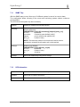
8.1
Overview
This page gives you an overview about the software version, the network configuration and the
system information.
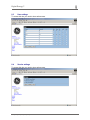
8.2
Network settings
To access this site you need to have write access.
OPM_CON_SNM_BAS_CRD_XGB_V070.doc
25/37
User Manual SNMP/Web Interface
g
Digital Energy™
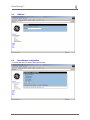
8.3
User settings
To access this site you need to have write access.
8.4
Service settings
To access this site you need to have write access.
OPM_CON_SNM_BAS_CRD_XGB_V070.doc
26/37
User Manual SNMP/Web Interface
g
Digital Energy™
8.5
DNS test
8.6
Speed/duplex configuration
To access this site you need to have write access.
OPM_CON_SNM_BAS_CRD_XGB_V070.doc
27/37
User Manual SNMP/Web Interface
g
Digital Energy™
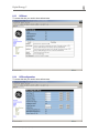
8.7
SNMP configuration
To access this site you need to have write access.
8.8
SNMP trap configuration
To access this site you need to have write access.
OPM_CON_SNM_BAS_CRD_XGB_V070.doc
28/37
User Manual SNMP/Web Interface
g
Digital Energy™
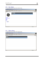
8.9
Email configuration
To access this site you need to have write access.
8.10
UPS Identification
OPM_CON_SNM_BAS_CRD_XGB_V070.doc
29/37
User Manual SNMP/Web Interface
g
Digital Energy™
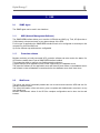
8.11
UPS Status
8.12
UPS Alarms
OPM_CON_SNM_BAS_CRD_XGB_V070.doc
30/37
User Manual SNMP/Web Interface
g
Digital Energy™
8.13
UPS test
To access this site you need to have write access.
8.14
UPS configuration
To access this site you need to have write access.
OPM_CON_SNM_BAS_CRD_XGB_V070.doc
31/37
User Manual SNMP/Web Interface
g
Digital Energy™
8.15
Save settings
To access this site you need to have write access.
8.16
Reboot settings
To access this site you need to have write access.
OPM_CON_SNM_BAS_CRD_XGB_V070.doc
32/37
User Manual SNMP/Web Interface
g
Digital Energy™
9 USE
9.1
SNMP Agent
The SNMP agent can be used in two situations:
9.1.1
NMS (Network Management Software)
The SNMP/WEB Interface allows you to monitor a UPS with any NMS (e.g. Tivoli, HP-Openview or
CA Unicenter) to detect and react on any status change of the UPS.
For this type of application the SNMP/WEB Interface needs to be configured to send traps to the
computer on which the NMS runs.
Up to four different trap addresses are configurable.
9.1.2
Protection software
Besides monitoring a locally connected UPS, protection software can also monitor the status of a
UPS via the network when it has an SNMP/WEB Interface installed.
This creates the ability to configure very flexible protection schemes.
A typical example is an application server, which is depending on a database server.
The protection software on the application server will detect a power failure on the database server
and will start to close all database connections before the database server itself shuts down.
9.2
Web Server
The built-in web server functionality enables the user to monitor and control the UPS with use of a
standard Internet browser.
The offered information of the web server gives a complete and detailed status overview in a very
user friendly way.
Besides measurement values of the UPS the complete configuration can be done via the web
browser.
OPM_CON_SNM_BAS_CRD_XGB_V070.doc
33/37
User Manual SNMP/Web Interface
g
Digital Energy™
10 Firmware upgrade
To update the firmware you need first to upload the new version by ftp and to start the upgrade
command by telnet or serial connection.
Depending on the version of firmware the previous settings can be lost.
Here you need to read the firmware documentation.
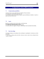
10.1
Firmware upload
Establish an ftp connection with the command:
ftp {[X.X.X.X]|[hostname]}
You need to define the IP-Address [X.X.X.X] or the full-qualified domain name [hostname] of the
updating SNMP interface card or box.
On the login name and password request you need to enter a username and the corresponding
password of who is allowed to access the ftp server and with write access.
Start with the following command to upload the new firmware:
put [path\][file]
Where [path\] corresponds to the path where the file is placed and [file] is the filename with
extension. After a successful upload a similar message is showed:
You can close the ftp session with the
quit
command.
After the upload you need to start immediately the upgrade without a reboot.
Otherwise the uploaded file will be deleted in the memory of the SNMP interface card or box.
10.2
Firmware upgrade
To upgrade the firmware you need to establish a telnet or RS232 connection.
The user needs to have write access.
The telnet session can be started with the
telnet {[X.X.X.X]|[hostname]}
You need to define the IP-Address [X.X.X.X] or the full-qualified domain name [hostname] of the
updating SNMP interface card or box.
On the login name and password request you need to enter a username and the corresponding
password of who is allowed to access the telnet server and with write access.
The upgrade can be started with the command
upgrade [file]
Where the [file] corresponds to the uploaded filename with extension.
After the upgrade the SNMP interface card or box reboots automatically if there is no interruption
after 3 seconds.
Depending on the version of firmware the previous settings can be lost.
More details can be found in the documentation of the new firmware.
If this occurs, please refer to the descriptions in Chapters 3 and 4 to reconfigure the card.
OPM_CON_SNM_BAS_CRD_XGB_V070.doc
34/37
User Manual SNMP/Web Interface
g
Digital Energy™
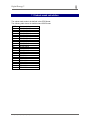
11 Subnet-mask calculation
The subnet mask needs to be defined in the CIDR format.
The following table shows the traditional and CIDR format.
CIDR
/32
/31
/30
/29
/28
/27
/26
/25
/24
/23
/22
/21
/20
/19
/18
/17
/16
/15
/14
/13
/12
/11
/10
/9
subnetmask format
255.255.255.255
255.255.255.254
255.255.255.252
255.255.255.248
255.255.255.240
255.255.255.224
255.255.255.192
255.255.255.128
255.255.255.0
255.255.254.0
255.255.252.0
255.255.248.0
255.255.240.0
255.255.224.0
255.255.192.0
255.255.128.0
255.255.0.0
255.254.0.0
255.252.0.0
255.248.0.0
255.240.0.0
255.224.0.0
255.192.0.0
255.128.0.0
OPM_CON_SNM_BAS_CRD_XGB_V070.doc
35/37
User Manual SNMP/Web Interface
g
Digital Energy™
12 Supported MIB Variables
MIB VARIABLE
POSSIBLE ALARMS
==== IDENTIFICATION Group ====
UpsIdentManufacturer
UpsIdentModel
UpsIdentUPSSoftwareVersion
UpsIdentAgentSoftwareVersion
upsIdentName
upsIdentAttachedDevices
==== ALARM ID ====
UpsAlarmBatteryBad
UpsAlarmOnBattery
UpsAlarmLowBattery
UpsAlarmDepletedBattery
UpsAlarmTempBad
UpsAlarmInputBad
UpsAlarmOutputBad
UpsAlarmOutputOverload
UpsAlarmOnBypass
UpsAlarmBypassBad
UpsAlarmOutputOffAsRequested
UpsAlarmUpsOffAsRequested
UpsAlarmChargerFailed
UpsAlarmUpsOutputOff
UpsAlarmUpsSystemOff
UpsAlarmFanFailure
UpsAlarmFuseFailure
upsAlarmGeneralFault
upsAlarmDiagnosticTestFailed
upsAlarmCommunicationsLost
upsAlarmAwaitingPower
upsAlarmShutdownPending
upsAlarmShutdownImminent
upsAlarmTestInProgress
==== BATTERY Group ====
UpsBatteryStatus
UpsSecondsOnBattery
UpsEstimatedMinutesRemaining
UpsEstimatedChargeRemaining
UpsBatteryVoltage
UpsBatteryCurrent
UpsBatteryTemperature
==== INPUT Group ====
UpsInputLineBads
UpsInputNumLines
UpsInputFrequency
UpsInputVoltage
upsInputCurrent
upsInputTruePower
==== OUTPUT Group ====
UpsOutputSource
UpsOutputFrequency
UpsOutputNumLines
UpsOutputVoltage
UpsOutputCurrent
UpsOutputPower
UpsOutputPercentLoad
SUPPORTED TRAPS
==== TRAP TYPE ====
upsTrapOnBattery
upsTrapTestCompleted
upsTrapAlarmEntryAdded
upsTrapAlarmEntryRemoved
==== ALARM Group ====
upsAlarmsPresent
==== CONTROL Group ====
UpsShutdownType
UpsShutdownAfterDelay
UpsStartUpAfterDelay
UpsRebootWithDuration
UpsAutoRestart
OPM_CON_SNM_BAS_CRD_XGB_V070.doc
36/37
User Manual SNMP/Web Interface
g
Digital Energy™
13 Support
13.1
First line support
Please contact your local General Electric Digital Energy distributor for any issues with
installation or use.
13.2
Internet Support
On-line support is also possible on request for users with Internet access.
13.3
Web Server Support
We will publish updates and patches on our Web server.
WWW.GEDIGITALENERGY.COM
We have a Web server running at www.gedigitalenergy.com.
With your Web browser you can access the latest information and product news for General
Electric Digital Energy.
OPM_CON_SNM_BAS_CRD_XGB_V070.doc
37/37
User Manual SNMP/Web Interface