1
series
USER’S MANUAL
Standard Expansion FB
for SX-Programmer Standard (Type: NP4H-SWN)
(Version: V2.0.0.0)
FEH589a
Preface
Thank you for purchasing Fuji Electric Programmable Controller MICREX-SX Series.
This User’s Manual explains the specifications and operations of the standard expansion FBs for Programming Support Tool
SX-Programmer Standard (type: NP4H-SWN).
Read this manual carefully to ensure correct operation. For MICREX-SX series, be sure to read the corresponding user’s
manual listed below.
Title
Manual No. Contents
User's Manual General Purpose Communication
Module, MICREX-SX series SPH
FEH225
Explains the specifications and operations of MICREX-SX
series general purpose communication module.
User's Manual SX-Programmer Standard
<Instruction>, MICREX-SX series SPH
FEH588
Explains the memory, instructions and system definitions of the
SPH series in the case of using SX-Programmer Standard.
User's Manual SX-Programmer Standard
<Reference>, MICREX-SX series SPH
FEH590
Explains the functions and the operations of SX-Programmer
Standard.
User's Manual Hardware, MICREX-SX series
SPH
FEH201
Explains the system configuration, the hardware specifications
and operations of modules in the MICREX-SX series.
* The above manuals can be downloaded from the following Fuji Electric FA Components & Systems Co., Ltd. site. In addition
to them, various manuals are also available there.
URL http://www.fujielectric.co.jp/fcs/eng/
* The standard expansion FBs are included in SX-Programmer Standard (type: NP4H-SWN)
Notes
Notes
1. This manual may not be reproduced in whole or part in any form without prior written approval by the manufacturer.
2. The contents of this manual (including specifications) are subject to change without prior notice.
Microsoft and Windows are trademarks or registered trademarks of Microsoft in the United States.
Pentium is a trademark or registered trademark of Intel in the United States.
Safety Precautions
Be sure to read the “Safety Precautions” thoroughly before using this product.
Caution
: Incorrect handling of the device may result in minor injury and/or physical damage.
Even some items indicated by “Caution” may result in a serious accident.
These safety instructions provide important information.
Be sure to strictly observe them. The items to be cared most are shown below:
Caution
Do not use one found damaged or deformed when unpacked, otherwise, failure or erratic operation might be caused.
Do not shock the product by dropping or tipping it over, otherwise, it might be damaged or troubled.
Do not play back the CD-ROM supplied with the product using an ordinary audio CD player, otherwise, you may get
your auditory sense or audio device damaged due to a loud sound.
Engage the CD-ROM or loader connector in a correct orientation, otherwise, an erratic operation might occur.
Sufficiently make sure of safety before program change, forced output, starting, stopping or anything else during a run.
The wrong operation might break or cause machine problems.
Be sure to keep within the software operating environment described in this manual when using this product, otherwise,
an erratic operation or a failure might be caused.
When operating the personal computer loader, be sure to select a stable place so that they won’t be dropped.
Otherwise, a failure might be caused.
Revision
*The manual No. is printed at the bottom right of the cover of this manual.
Printed on
*Manual No.
Revision contents
Jun. 2004
FEH589
First edition
Mar. 2006
FEH589a
Counter FBs and positioning FBs were added.
Specifications for FBs supporting array/structure were added.
Contents
Preface
Safety Precautions
Revision
Contents
Page
Section 1 General ....................................................................................... 1-1
1-1 List of Standard Expansion FBs for General Purpose Communication Module ...................... 1-1
1-2 List of High-speed Counter Standard Expansion FBs ................................................................. 1-1
1-3 List of Simple Positioning Standard Expansion FBs .................................................................. 1-1
Section 2 Installation .................................................................................. 2-1
2-1 Personal Computer Environment Necessary for Standard Expansion FBs .............................. 2-1
2-2 Installation Procedure ................................................................................................................... 2-2
2-3 Method of Using Expansion FB ..................................................................................................... 2-5
2-3-1 Importing programs ............................................................................................................................ 2-5
2-3-2 Reading of expansion FB ................................................................................................................... 2-8
2-4 Uninstall .......................................................................................................................................... 2-9
Section 3 Specifications of Communication FB ..................................... 3-1
3-1 Non-procedural FB ......................................................................................................................... 3-1
3-1-1
3-1-2
3-1-3
3-1-4
3-1-5
3-1-6
3-1-7
General ................................................................................................................................................ 3-1
Memory capacity for using non-procedural FB .................................................................................. 3-2
Communication specifications for non-procedural FB ..................................................................... 3-3
Initialization .......................................................................................................................................... 3-8
Data sending ..................................................................................................................................... 3-12
Data receiving ................................................................................................................................... 3-13
RAS .................................................................................................................................................... 3-14
3-2 FUJI General Purpose Inverter Procedure FB “_CfdFRN” ........................................................ 3-15
3-2-1
3-2-2
3-2-3
3-2-4
3-2-5
General .............................................................................................................................................. 3-15
Specifications for _CfdFRN .............................................................................................................. 3-16
Initialization ........................................................................................................................................ 3-20
Data sending/receiving ..................................................................................................................... 3-22
RAS .................................................................................................................................................... 3-24
3-3 FUJI General Purpose Inverter Standard Communication (FGI-BUS)
Procedure FB “_CfdFVR” ............................................................................................................. 3-25
3-3-1
3-3-2
3-3-3
3-3-4
3-3-5
General .............................................................................................................................................. 3-25
Specifications for _CfdFVR ............................................................................................................... 3-26
Initialization ........................................................................................................................................ 3-30
Data sending/receiving ..................................................................................................................... 3-32
RAS .................................................................................................................................................... 3-34
3-4 Communication Protocol Included General Purpose Inverter Procedure FB “_Cfvrpr” ........ 3-35
3-4-1
3-4-2
3-4-3
3-4-4
3-4-5
General .............................................................................................................................................. 3-35
Specifications for _Cfvrpr .................................................................................................................. 3-36
Initialization ........................................................................................................................................ 3-40
Data sending/receiving ..................................................................................................................... 3-42
RAS .................................................................................................................................................... 3-44
Contents
Page
3-5 FUJI Temperature Controller Procedure FB “_CfdPYX” ........................................................... 3-45
3-5-1
3-5-2
3-5-3
3-5-4
3-5-5
General .............................................................................................................................................. 3-45
Specifications for _CfdPYX ............................................................................................................... 3-46
Initialization ........................................................................................................................................ 3-50
Data sending/receiving ..................................................................................................................... 3-52
RAS .................................................................................................................................................... 3-54
3-6 FUJI Bar Code Reader Procedure FB “_CfdPK” ........................................................................ 3-55
3-6-1
3-6-2
3-6-3
3-6-4
3-6-5
3-6-6
General .............................................................................................................................................. 3-55
Specifications for _CfdPK ................................................................................................................. 3-56
Initialization ........................................................................................................................................ 3-60
Data sending ..................................................................................................................................... 3-62
Data receiving ................................................................................................................................... 3-63
RAS .................................................................................................................................................... 3-64
3-7 MODBUS Procedure FB “_C_modm” .......................................................................................... 3-65
3-7-1
3-7-2
3-7-3
3-7-4
3-7-5
General .............................................................................................................................................. 3-65
Specifications for _C_modm ............................................................................................................ 3-66
Initialization ........................................................................................................................................ 3-75
Data sending/receiving ..................................................................................................................... 3-78
RAS .................................................................................................................................................... 3-80
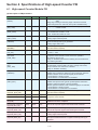
Section 4 Specifications of High-speed Counter FB .............................. 4-1
4-1 High-speed Counter Module FB .................................................................................................... 4-1
4-1-1
4-1-2
4-1-3
4-1-4
4-1-5
4-1-6
4-1-7
4-1-8
4-1-9
Overview of FB ..................................................................................................................................... 4-1
Memory size of FB ............................................................................................................................... 4-2
Operation modes of FB ...................................................................................................................... 4-2
Control specifications ......................................................................................................................... 4-3
Details of operation modes ................................................................................................................ 4-4
Error information ................................................................................................................................. 4-8
High-speed counter FB (muitifunctional version) _MHCNTR/_MHCNTRa .................................. 4-12
High-speed counter FB (standard version) _MHCNTH/_MHCNTHa ........................................... 4-17
Multichannel counter FB _MHCNTM/_MHCNTMa ......................................................................... 4-20
4-2 High-speed Input Module Counter FB ......................................................................................... 4-23
4-2-1
4-2-2
4-2-3
4-2-4
4-2-5
4-2-6
Overview of FB ................................................................................................................................... 4-23
Memory size of FB ............................................................................................................................. 4-23
Count operation mode ...................................................................................................................... 4-24
Sample Applications of Counter Expansion FB ............................................................................... 4-25
Details of high-speed input module counter FB ............................................................................. 4-26
Settings for ring and gate operations .............................................................................................. 4-29
Section 5 Specifications of Simple Positioning FB ................................ 5-1
5-1 Overview of Simple Positioning ................................................................................................... 5-1
5-2 Specifications of Simple Positioning FB ..................................................................................... 5-2
5-2-1
5-2-2
5-2-3
5-2-4
5-2-5
5-2-6
5-3-7
5-3-8
Functions of simple positioning FB ................................................................................................... 5-2
Simple positioning FB list .................................................................................................................. 5-2
Memory size of simple positioning FB ............................................................................................... 5-2
Placement of positioning FB .............................................................................................................. 5-3
Positioning FB _MSMOV ................................................................................................................... 5-4
SData setting FB _MSMVDAT ............................................................................................................ 5-8
Machine coordinates position preset .............................................................................................. 5-21
Cancellation of positioning ............................................................................................................... 5-22
Contents
Page
5-3 Details of Positioning Function .................................................................................................... 5-11
5-3-1 Positioning operation condition ....................................................................................................... 5-11
5-3-2 PTP positioning operation ................................................................................................................ 5-12
5-3-3 Manual operation .............................................................................................................................. 5-14
5-3-4 Origin-return operation ..................................................................................................................... 5-17
5-3-5 Frequency changeover ..................................................................................................................... 5-19
5-3-6 Work coordinates position preset .................................................................................................... 5-20
5-3-9 Pause ................................................................................................................................................ 5-24
5-3-10 Forcible stop .................................................................................................................................... 5-26
5-3-11 OT error ............................................................................................................................................ 5-28
5-3-12 SOT error .......................................................................................................................................... 5-30
5-3-13 Acceleration and deceleration ........................................................................................................ 5-32
5-3-14 Deceleration point detection ........................................................................................................... 5-34
5-3-15 Position data management ............................................................................................................. 5-35
5-3-16 Frequency data management ......................................................................................................... 5-38
5-3-17 Operation when the data setting FB is used .................................................................................. 5-39
5-3-18 Outputting the set data of local FB (when the data setting FB is used) ........................................ 5-40
5-4 Parameters for Simple Positioning Expansion FB .................................................................... 5-43
5-4-1 Simple positioning parameter specifications ................................................................................. 5-44
5-5 Pulse Output Setting for High-speed Output Module ................................................................. 5-47
Appendix 1 Data Type and Range ..................................................... App.1-1
Section 1 General
Communication program for MICREX-SX series to communicate data with external devices via the general purpose
communication module is made using the function blocks dedicated to communication (“function block” will be abbreviated to
“FB” below). The following FBs are prepared for communication purpose:
* “a” is suffixed to the name of the FB supporting array/structure.
1-1 List of Standard Expansion FBs
for General Purpose Communication Module
The following standard expansion FBs are prepared for the general purpose communication module. The standard expansion
FBs are included with “SX-Programmer Standard”.
Type
Non-procedural FB
FB name
FB Overview
_C_free
Non-procedural FB
Send: 512 words Receive: 512 words
_Cfr252
Non-procedural FB
Send: 252 words Receive: 252 words
_Cfr128
Non-procedural FB
Send: 128 words Receive: 128 words
_Cfr64
Non-procedural FB
Send: 64 words Receive: 64 words
_Cfr32
Non-procedural FB
Send: 32 words Receive: 32 words
_Cfrpr
Non-procedure FB which built into communication protocol
Send: 512 words Receive: 512 words
The program capacity is reduced by performing a part of the communication processing
with the module.
_Cfrp2
Non-procedure FB which built into communication protocol
Send: 512 words Receive: 512 words
The program capacity is reduced by performing a part of the communication processing
with the module. In addition, communication processing can be performed at high-speed
by using two communication ports.
_CfdFRN
For FUJI Inverter FRENIC series
_CfdFVR
For FUJI Inverter FVR-C11 series (FGI-BUS)
_Cfvrpr
For FUJI Inverter FVR-C11 series (FGI-BUS)
The program capacity is reduced by performing a part of the communication processing
with the module.
For FUJI Inverter
For FUJI temperature controller PYX series and PYH series
For FUJI temperature
controller
_CfdPYX
For FUJI bar code
_CfdPK
For FUJI bar code reader PK2 series
For MODBUS
_C_modm
MODBUS procedure FB communicates data with MODBUS slave statins, making
MICREX-SX the master station.
1-2 List of High-speed Counter Standard Expansion FBs
Type
Counter FB
FB name
FB overview
_MHCNTR
High-speed counter (multifunctional version) FB
_MHCNTH
High-speed counter (simple-function version) FB
_MHCNTM
Multiple channel counter FB
_MHCNTD
High-speed input module counter FB
1-3 List of Simple Positioning Standard Expansion FBs
Type
Simple Positioning FB
FB name
FB overview
_MSMOV
One-axis PTP positioning FB
_MSMVDAT One-axis PTP positioning data setting FB
1-1
Section 2 Installation
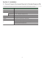
2-1 Personal Computer Environment Required for Strandard Expansion FBs
To use standard expansion FBs, the operating environment of SX-Programmer Standard plus the hard disk capacity necessary
to install the expansion FBs that you want to use are required as personal computer operating environment.
Item
Specifications
Personal computer
IBM-AT compatible
CPU
Intel Pentium 233 MHz or higher is recommended.
Hrad disk
200MB or more
External storage
Necessary for installation
Floppy disk drive Min. 1 unit, 1.25M bytes/1.44M bytes (3.5 inch)
CD-ROM drive
Min. 1 unit (Quadruple speed or higher device is recommended.)
Memory capacity
Min. 64 MB
Mouse
USB mouse, serial mouse, bus mouse, or PS2 mouse
Keyboard
106 Japanese (A01) keyboard (Ctrl + alphanumeric)
Display
Resolution: 800 x 600 dots or higher, 1024 x 768 dots or higher is recommended
Windows95/98/ME English version
OS
WindowsNT WorkstationV4.0 English version SP6 or highrer
Windows2000 Professional English version
WindowsXP English version
2-1
Section 2 Installation
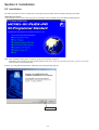
2-2 Installation
The standard expansion FB is included in the SX-Programmer Standard System Software Package (CD-ROM).
<Operating Procedure>
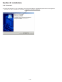
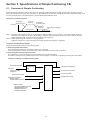
1) Activate Windows and then insert the product CD-ROM into the CD-ROM drive. The following dialog appears.
Note: If the installation dialog does not appear, perform the following operations:
Click [Start] on the Windows screen and then [RUN]. Enter (drive where the CD-ROM is inserted) : \autorun.exe for the
name, and then click the [OK] button.
2) When you click [Standard Expansion FB Setup], the following dialog appears.
First, click here.
2-2
Section 2 Installation
2-2 Installation
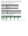
3) When you click the [Next>] button in the [Welcome] dialog, the [License Agreement] dialog appears.
After reading the contents thoroughly, move on to the next operation.
4) When you click the [Next>] button in the [License Agreement] dialog, the [Choose Designation Location] dialog appears.
Specify the target folder, and then click the [OK] button to start the installation processing.
The target folder appears here.
To change the target folder, click the [Browse...] button. The [Choose Folder] dialog appears. Specify a folder, and then click the
[OK] button to return control to the [Choose Destination Location] dialog.
“LIBRARIES” and “SAMPLES” folders are hierarchically created under the target folder.
LIBRARIES folder D The compressed project (*.Zpj) which contains the expansion FBs is stored.
SAMPLES folder D Sample programs are stored in the compressed project (*.Zpj) format.
2-3
Section 2 Installation
2-2 Installation
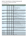
5) When installation is completed, the following [InstallShield Wizard Complete] dialog appears. Click the [Finish] button to
complete the installation procedure.
When you check here and then click the
[Finish] button, the product information of
the standard expansion FB appears.
<Example of release note>
2-4
Section 2 Installation
2-3 How to Use Expansion FBs
2-3-1 Importing programs
Individual communication FBs included in the standard expansion FB package can be used by importing programs into a
created project.
<Operation>
When you execute the [Import Programs...] command in the [File] menu, the [Import Programs] dialog appears.
Click the [Browse] button and then select a project which is a import source.
The imported project is stored in the compressed project (*.Zpj) format in the “LIBRARIES” folder under the folder where
this expansion FB is installed.
2-5
Section 2 Installation
2-3 How to Use Expansion FBs
Select the compressed project, and then click the [OK] button. The compressed project is extracted and the following dialog
appears.
Programs in the project are displayed.
Note:
When importing programs, _C2VER
is not necessary (dummy program).
Therefore, uncheck its box.
See note.
When you click the [All Select] button, all the programs in the project are selected. Select all of them, and click the [OK]
button to display the following dialog.
2-6
Section 2 Installation
2-3 How to Use Expansion FBs
Click the [OK] button. The program is imported into the programs folder in the project tree.
Program imported into project
2-7
Section 2 Installation
2-3 How to Use Expansion FBs
2-3-2 Reading of expansion FB
The method of reading the imported expansion FB to the program of the program type is explained below.
When you click the position to insert the expansion FB to be used with the [USERFB] button selected, the [Address Entry]
dialog appears.
Click here.
Set the expansion FB to be used and the FB instance number, and then click the [OK] button.
The [Parameter Entry] dialog appears. Enter devices and constants to each parameter, and then click the [OK] button.
The expansion FB is called to the program.
* For the specifications for individual expansion FBs (explanation of parameters, etc.) refer to “Section 3 Specifications for
Communication FB.”
2-8
Section 2 Installation
2-4 Uninstallation
<Operation>
1) Activate “Add/delete application” from the Control Panel window. The figure below shows an example of WindowsXP screen
image.
2) Select “Standard Expansion FB for SX-Programmer Standard Ver∗.∗.∗.∗” and click the [Change/Remove] button. The
following confirmation screen for file deleting appears.
3) Clicking the [OK] button on the confirmation screen starts uninstalling the “Standard Expansion FB for SX-Programmer
Standard” file. When uninstalling is completed, a message to the effect is displayed.
2-9
Section 2 Installation
2-4 Uninstall
(3) Clicking the [OK] button on the comfirmation screen starts uninstalling the “Standard Expansion FB for SX-Programmer
Standard” file. When uninstalling is completed, a message to the effect is displayed.
2-10
Section 3 Specifications of Communication FB
3-1 Non-procedural FB
3-1-1 General
For communication between MICREX-SX series and external device via RS-232C or RS-485 (NP1L-RS1/2/4), the “nonprocedural” FB included with the loader is used. The non-procedural FB carries out data communications between the CPU
module and external devices using the start-stop synchronization type non-procedural transmission protocol. Seven types of
non-procedural FB are prepared, as shown below.
FB Name
Specification Overview
_C_free/_C_freea
Non-procedural FB Send: 512 words, Receive: 512 words
_Cfr252/_Cfr252a
Non-procedural FB Send: 252 words, Receive: 252 words
_Cfr128/_Cfr128a
Non-procedural FB Send: 128 words, Receive: 128 words
_Cfr64/_Cfr64a
Non-procedural FB Send: 64 words, Receive: 64 words
_Cfr32/_Cfr32a
Non-procedural FB Send: 32 words, Receive: 32 words
(See note 1)
_Cfrpr/Cfrpra
Non-procedural FB with a built-in communication protocol
Send: 512 words, Receive: 512 words
The program capacity is reduced by performing a part of the communication
processing with the module.
(See note 1)
_Cfrp2/_Cfrp2a
Non-procedural FB with a built-in communication protocol
Send: 512 words, Receive: 512 words
The program capacity is reduced by performing a part of the communication
processing with the module. In addition, communication processing can be
performed at high-speed by using two communication ports.
* “a” is suffixed to the name of the FB supporting array/structure.
Note 1: Non-procedural FB with a built-in communication protocol performs part of communication processing in the firmware
in the module. Therefore, to use this FB, V2536 or later version (V2535 or later version for “_Cfrpr”) of general purpose
communication module is necessary.
Note 2: When using FBs supporting array/structure, use V2.2.3.0 or later version of Standard loader.
The “non-procedural” FB performs the following operations:
1) Initialization of communication ports
Initializes RS-232C and RS-485 ports. (sets transmission speed, data bit length, parity bits, etc., so as to match the external
device.)
2) Data sending/receiving function
Sends the data from an application in the CPU of MICREX-SX series via the general purpose communication module to an
external device, or outputs the data received via the general purpose communication module to an application.
3) Monitoring of transmission condition
Monitors the condition of data transmission and, if abnormal, outputs error information.
<FB operating conditions>
System configuration:
One FB is necessary for each external device which is connected by RS-232C or RS485 to one general purpose communication
module. However, when RS-232C/RS485 signal conversion is enabled (the mode selection switch is set to 4) for the general
purpose communication, each FB is used by two channels.
3-1
Section 3 Specifications of Communication FB
3-1 Non-procedural FB
3-1-2 Memory capacity for using non-procedural FB
The non-procedural FBs use the following memories:
FB name
Program
area
User FB
instance
System FB
instance
Standard memory or Retain memory
_C_free/_C_freea
Approx.
3.4k steps
772 worss
82 words
Approx. 3.7k words
(For user send/receive area: Approx. 1.1k words)
_Cfr252/_Cfr252a
Approx.
3.5k steps
892 words
82 words
Approx. 2.2k words
(For user send/receive area: Approx. 0.51k words)
_Cfr128/_Cfr128a
Approx.
3.5k steps
892 words
82 words
Approx. 1.9k words
(For user send/receive area: Approx. 0.26k words)
_Cfr64/_Cfr64a
Approx.
3.5k steps
892 words
82 words
Approx. 1.8k words
(For user send/receive area: Approx. 0.13k words)
_Cfr32/_Cfr32a
Approx.
3.5k steps
892 words
82 words
Approx. 1.7k words
(For user send/receive area: Approx. 0.07k words)
_Cfrpr/_Cfrpra
Approx.
1.5k steps
244 words
58 words
Approx. 1.7k words
(For user send/receive area: Approx. 1.1k words)
_Cfrp2/_Cfrp2a
Approx.
1.6k steps
268 words
84 words
Approx. 1.7k words
(For user send/receive area: Approx. 1.1k words)
Note 1: The above list for the memory capacity includes the area for the main body of non-procedural FB and those for subFBs that are called from the non-procedural FB.
Note 2: The above list for standard memory and retain memory includes the memory capacity necessary for sending/receiving
data.
3-2
Section 3 Specifications of Communication FB
3-1 Non-procedural FB
3-1-3 Communication specifications for non-procedural FB
(1) Communication specifications
Item
Specification
Transmission speed
300/600/1200/2400/4800/9600/19200/38400/57600/76800/115200 bps
Data bits
Selected from 7/8 bits
Parity bit
Selected from none/odd/even
Stop bits
Selected from 1/2 bits
DCE
Selected from DTE/DCE/modem DTE mode
Modem DTE mode: Turn CD ON when receiving
Signal control
Signal flow
control
DTE mode
ER: always ON
DCE mode
DR: always ON
DTE mode
Off RS: always ON; Sending: unconditional
On RS: ON during sending; Sending: when CS is ON
DCE mode
Off CS: always ON; Sending: unconditional
On CS: ON when RS is ON; Sending: when ER is ON
(Note)
XON/XOFF control
Selected from ON/OFF
*To use flow control with XON and XOFF, XON and XOFF must not occur in data.
RS-485 mode
Selected from 4-wire/2-wire
Code conversion
Selected from none/ASCII conversion/ EBCDIC conversion
None
Frame detection Fixed length
Disable frame detection function.
Designate the number of receive data bytes
Variable length
Designate start and end codes.
None
None
Horizontal parity Upper order/Lower order
(BCC)
Lower order/Upper order
Calculation range designation. Designate position.
Formula: Selected from add/add and invert/EOR/CRC
BCC code: Selected from character code/binary/code
Transmission timer value
(Set value) * 10ms
Note: The non-procedural FBs that can select the transmission speed of 300, 600, 76800 and 115200 bps are “_Cfrpr” and
“_Cfrp2”.
V2535 or later version of general purpose communication module can use the “_Cfrpr” FB; V2536 or later version of
general purpose communication module can use the “_Cfrp2” FB.
3-3
Section 3 Specifications of Communication FB
3-1 Non-procedural FB
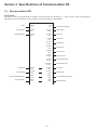
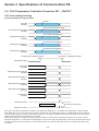
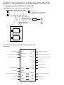
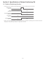
(2) FB format
The format of the non-procedural FB is as follows. The figure below is an example of “_C_free”, however, other non-procedural
FBs have the same formats (the same parameter names and number of parameters).
_C_free/_C_freea
Open
OK
V8
OPEN
V1
Communication ready
Send request
S_REQ
V2
O_STS
WV9
Open status
Send data length
S_LEN
WV3
S_END
V10
Send end
S_ERR
V11
Send error
S_STS
WV12
Send status
R_END
V13
Receive end
R_ERR
V14
Receive error
R_STS
WV15
Receive status
R_LEN
WV16
Receive data length
STN_NO
WV17
RS-485 station No.
Send data
S_DAT
WV4
S_DAT
WV4
Send data
Receive data
R_DAT
WV5
R_DAT
WV5
Receive data
Communication parameter
PARA
WV6
PARA
WV6
RAS infomation
RAS
WV7
RAS
WV7
3-4
Communication parameter
RAS infomation
Section 3 Specifications of Communication FB
3-1 Non-procedural FB
(3) Explanation of FB parameters
Parameter name
Data type
I/O
Description
Open
(OPEN)
V0001
BOOL
IN
ON: Sends the "communication parameters" to the general
purpose communication module to initialize communication.
When communication becomes possible, "communication
ready" turns ON.
OFF: Performs the processing for ending communication.
"Communication ready" turns OFF.
Send request
(S_REQ)
V0002
BOOL
IN
Starts to send data. When sending has ended, this needs to be
turned OFF by the application program.
Send data length
(S_LEN)
WV0003
INT
IN
Designates the length of send data by the number of bytes.
Send data
(S_DAT)
WV0004
WORD
IN_OUT Stores send data.
Receive data
(R_DAT)
WV0005
WORD
IN_OUT Stores received data.
Communication
parameter
(PARA)
WV0006
WORD
IN_OUT Stores the initialization parameters.
RAS information
(RAS)
WV0007
WORD
IN_OUT Operating information of this FB.
Communication ready
(OK)
V0008
BOOL
OUT
Turns ON when initialization has ended normally to indicate that the
system is ready for sending/receiving data.
Open status
(O_STS)
WV0009
INT
OUT
2-digit hexadecimal code to indicate the result of initialization.
Send end
(S_END)
V0010
BOOL
OUT
Turns ON when sending has completed.
Send error
(S_ERR)
V0011
BOOL
OUT
Turn ON if a send error has occurred.
Send status
(S_STS)
WV0012
INT
OUT
Code to indicate the result of sending
Receive end
(R_END)
V0013
BOOL
OUT
Turns ON when receiving has completed.
Receive error
(R_ERR)
V0014
BOOL
OUT
Turns ON if a receive error has occurred.
Receive status
(R_STS)
WV0015
INT
OUT
Code to indicate the result of receiving
Receive data length
(R_LEN)
WV0016
INT
OUT
Outputs the received data length.
RS-485 station No.
(STN_NO)
WV0017
INT
OUT
The condition of the RS-485 station number setup switch of the
general purpose communication module is output to this pin.
* For more information about data type, refer to “Appendix 1.”
3-5
Section 3 Specifications of Communication FB
3-1 Non-procedural FB
<Send data parameter; format of the memory assigned to “WV0004”>
The memory that is assigned to WV0004 must be set (secured) as follows.
Specify the start address of the memory for WV0004.
Upper order
Start address
Lower order
WM(WL)****
Data 2
Data 1
WM(WL)****+1
Data 4
Data 3
WM(WL)****+31
Data 64
Data 63
Up to here is assigned to _Cfr32.
WM(WL)****+63
Data 128
Data 127
Up to here is assigned to _Cfr64.
WM(WL)****+127
Data 256
Data 255
Up to here is assigned to _Cfr128.
WM(WL)****+251
Data 504
Data 503
Up to here is assigned to _Cfr252.
WM(WL)****+511
Data 1024
Data 1023
Up to here is assigned to
_C_free,_Cfrpr,_Cfrpr2.
* The size of send data is maximum 1024 bytes including start code, end code and BCC when code conversion is not to be
performed.
<Receive data parameter; format of the memory assigned to “WV0005”>
The memory that is assigned to WV0005 must be set (secured) as follows.
Specify the start address of the memory for WV0005.
Upper order
Start address
Lower order
WM(WL)****
Data 2
Data 1
WM(WL)****+1
Data 4
Data 3
WM(WL)****+31
Data 64
Data 63
Up to here is assigned to _Cfr32.
WM(WL)****+63
Data 128
Data 127
Up to here is assigned to _Cfr64.
WM(WL)****+127
Data 256
Data 255
Up to here is assigned to _Cfr128.
WM(WL)****+251
Data 504
Data 503
Up to here is assigned to _Cfr252.
WM(WL)****+511
Data 1024
Data 1023
Up to here is assigned to
_C_free,_Cfrpr,_Cfrpr2.
* The size of receive data is maximum 1024bytes including start code, end code and BCC when code conversion is not to be
performed.
3-6
Section 3 Specifications of Communication FB
3-1 Non-procedural FB
<Communication parameter; format of the memory assigned to “WV0006”>
The memory that is assigned to WV0006 must be set (secured) as follows. This format is common to all non-procedural FBs.
Specify the start address of the memory for WV0006.
Start address
WM(WL)***
General purpose communication
module station No.
WM(WL)***+20 Start code1
WM(WL)***+1
Port No.
WM(WL)***+2
Message port No.
WM(WL)***+3
Message port No.2
WM(WL)***+4
Transmission speed
WM(WL)***+5
Data bit
WM(WL)***+6
Parity bit
WM(WL)***+7
Stop bit
WM(WL)***+8
DCE designation
WM(WL)***+9
ER/DR signal control
WM(WL)***+10
Signal flow control
WM(WL)***+11
XON/XOFF control
WM(WL)***+12
RS-485 mode
WM(WL)***+13 to 15
WM(WL)***+19 Number of start codes bytes
WM(WL)***+21 Start code2
WM(WL)***+22 Start code3
WM(WL)***+23 Start code4
WM(WL)***+24 Start code5
WM(WL)***+25 Number of end codes bytes
WM(WL)***+26 End code1
WM(WL)***+27 End code2
WM(WL)***+28 End code3
WM(WL)***+29 End code4
WM(WL)***+30 End code5
WM(WL)***+31 BCC designation
WM(WL)***+32 Calculation range, position
Reserved
WM(WL)***+33 Calcuration formula
WM(WL)***+16
Code conversion
WM(WL)***+17
Frame detection
WM(WL)***+18
Number of receive data bytes
WM(WL)***+34 Code type
WM(WL)***+35 Send timer value
WM(WL)***+36 to 39 Reserved
<RAS information; format of the memory assigned to “WV0007”>
The memory that is assigned to WV0007 must be set (secured) as follows. This format is common to all non-procedural FBs.
Specify the start address of the memory for WV0007.
Start address
_Cfrpr,_Cfrpr2
Start address
WM(WL)****
WM(WL)****
Work area for sending
(256 words)
Work area for receiving
(256 words)
WM(WL)****+256
WM(WL)****+511
WM(WL)****+511
WM(WL)****+512
WM(WL)****+512
WM(WL)****+531
RAS area
(20 words)
Start address
WM(WL)****+1535
_C_fr252, _Cfr128
_Cfr64, _Cfr32
WM(WL)****
Work area for sending
(256 words)
WM(WL)****+255
WM(WL)****+255
WM(WL)****+256
_C_free
Work area for sending
(256 words)
WM(WL)****+255
Work area for receiving
(256 words)
WM(WL)****+256
WM(WL)****+511
Work area for receiving
(256 words)
WM(WL)****+512
Receove buffer area
(1024 words)
WM(WL)****+1536
WM(WL)****+1023
Receove buffer area
(512 words)
WM(WL)****+1024
Send buffer area
(1024 words)
WM(WL)****+2559
Send buffer area
(512 words)
WM(WL)****+1535
WM(WL)****+2560
RAS area
(20 words)
WM(WL)****+2579
3-7
WM(WL)****+1536
WM(WL)****+1555
RAS area
(20 words)
Section 3 Specifications of Communication FB
3-1 Non-procedural FB
3-1-4 Initialization
(1) Initialization parameters
In order to initialize each individual port of the general purpose communication module, it is necessary to set values which
match the communication specifications of the object external device to the individual communication parameters. The table
below shows the setting contents of these parameters.
No.
Item
Description
0
General purpose communication
module station No.
Sets the station number of the general purpose communication module on the SX
bus.
1
Port No.
Designates an interface port on general purpose communication module.
0: RS-232C port
1: RS-485 port
2
Message port No. 1
Designates a port No. for sending/receiving messages to/from a general purpose
communication module (1 to 127).
Note: Avoid designating a port No. which is already used for sending/receiving
messages to/from other module.
3
Message port No. 2
* For _Cfrpr2 only
Designates a port No. for sending/receiving messages to/from a general purpose
communication module (1 to 127).
Note: Avoid designating message port No. 1 or a port No. which is already used for
sending/receiving messages to/from other module.
4
Transmission speed
Designates the transmission speed.
0: 1200, 1: 2400, 2: 4800, 3: 9600, 4: 19200, 5: 38400, 6: 57600, 7: 76800,
8: 115200, 90: 300, 91:600 bps
Note: 7, 8, 90 and 91 can be set for _Cfrpr or _Cfrpr2 only.
5
Data bit
Designates the data bit length. When "7" is selected, 7 bits make up one data; when
"8," 8 bits make up one data.
0: 7 bits, 1: 8 bits
6
Parity bit
This is a bit which is added to data for the purpose of error detection. Designate the
proper one to match the setting of the device at the other end.
0: None, 1: Odd, 2: Even
7
Stop bit
This bit indicates the end of data. Designate the proper one to match the setting of
the device at the other end.
0: 1 bit, 2: 2 bits
When signal line control is not performed, there is no difference in functions between
DCE and DTE modes. The RS-232C of the general purpose communication module
is of DTE specification, however, it can be used as a DCE specification interface
when signal lines are converted as follows:
8
DCE designation
No. 7 pin (RS) to CS
No. 8 pin (CS) to RS
No. 6 pin (DR) to ER
No. 4 pin (ER) to DR
0: DTE, 1: DCE, 2: Modem DTE
9
10
ER/DR signal control
Signal flow control
XON/XOFF control
11
0: Off, 1: On
DTE mode
0: Off RS: always ON; Sending: unconditional
1: On RS: ON while sending; Sending: when CS is ON
DCE mode
0: Off CS: always ON; Sending: unconditional
1: On CS: ON when RS is ON; Sending: when ER is ON
Because communication between sender and receiver is performed asynchronously,
flow control may be necessary. The receiver sends an XOFF signal to indicate that it
cannot receive data for a while and then sends an XON signal to cancel the XOFF
condition. To use XON/OFF control, the device at the other end must also have this
function.
0: NO, 1: YES
12
RS-485 mode
Selects 4-wire or 2-wire for RS-485.
0: 4-wire, 1: 2-wire
13
Reserved
Not used
3-8
Section 3 Specifications of Communication FB
3-1 Non-procedural FB
0: 4-wire, 1: 2-wire
13
Reserved
Not used
14
Reserved
15
Reserved
16
Code conversion
Converts binary data into a character string variable.
0: None, 1: ASCII conversion, 2: EBCDIC conversion
17
Frame detection
Designates data receiving method.
0: None
Receiving completes when data is received.
1: Variable length Receiving completes when the data in a range between start
and end codes is received.
2: Fixed length
Receiving completes when receive data reaches the specified
number of receive data bytes.
18
Number of receive data bytes
Designates the number of receive data bytes when "Fixed length" is selected for
frame detection. When "Variable length" is selected, set this item to "0."
19
Number of start code bytes
Designates the number of start code bytes when "Variable length" is selected.
20
Start code 1
Designates start code when "Variable length" is selected.
21
Start code 2
22
Start code 3
23
Start code 4
24
Start code 5
25
Number of end code bytes
Designates the number of end code bytes when "Variable length" is selected.
26
End code 1
Designates end code when "Variable length" is selected.
27
End code 2
28
End code 3
29
End code 4
30
End code 5
Sets whether or not to add horizontal parity for checking text data transmission error.
0: None
1: Set in the order of upper- and lower-order byte
31
BCC designation
Upper byte of BCC Lower byte of BCC
2: Set in the order of lower- and upper-order byte
Lower byte of BCC Upper byte of BCC
Sets the calculation range and BCC position.
: Calculation range
0: Calculates the text part and enters it ahead of the end code.
Start code TEXT BCC End code
(Note)
1: Calculates text part and end code and inserts them behind the end code.
Start code TEXT End code BCC
32
Calculation range, position
2: Calculates start code and text part and inserts them ahead of the end code.
Start code TEXT BCC End code
(Note)
3: Calculates start code, text part and end code and inserts them behind the end code.
Start code TEXT End code BCC
Note: In this case, the BCC code type cannot be designated as “binary.”
Specify other than CR-16 for the BCC expression.
3-9
Section 3 Specifications of Communication FB
3-1 Non-procedural FB
Calculation method to check for transmission error.
D1 D2
Dn
0: Add
D1 + D2 +
+ Dn
1: Add and invert
33
BCC calculation formula
Inversion of (D1 + D2 +
+ Dn)
2: EOR
D1 EOR D2 EOR
3: CRC
EOR Dn
Note: When CRC is selected, specify “BCC Code Format” to “0: Binary.”
CRC-16: X16 +X 15 +X 2 +1
BCC code type
Designates the code type of BCC data.
0: Binary
1: ASCII
2: EBCDIC
35
Send timer value
The timer for monitoring during the period from when the CPU module (FB) sends a
send request to an external device until communication ends. This value can be set in
0.01-second steps.
Example: For 1 second, set this value to "100". Up to 327.67 seconds can be set.
36
:
39
Reserved
34
Not used
Note 1: Parameter Nos.16 to 35 are valid even if changed after opening.
After opening, if parameter Nos.16 to 35 are changed and a setup error occurs, or if other parameters are changed, an
open error results and communication “OK” is turned OFF.
Note 2: No. in the above table is the number of the words from the start for communication parameter.
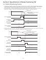
(2) Initialization procedure
When the OPEN (V0001) parameter of FB is turned ON, communication parameters are transferred to the general purpose
communication module, which executes processing for initialization. If initialization is impossible due to a communication
parameter setting error or hardware error, FB outputs the corresponding error code to the OPEN Status (WV0009).
Turned ON by the application program.
OPEN request
(V0001)
Processing for initialization
Turned OFF by the application program.
Port closing operation
Communication ready
(V0008)
Note: OPEN signal shall be set to Always ON during data communication.
If initialization error has occurred
OPEN Status
(WV0009)
00
Error status
3-10
Section 3 Specifications of Communication FB
3-1 Non-procedural FB
(3) OPEN status list
No.
Result of initialization
Remarks
'00'
Ended normally
'01'
Transmission speed error
General purpose communication module detected an error.
'02'
Data bit length error
General purpose communication module detected an error.
'03'
Parity bit error
General purpose communication module detected an error.
'04'
Stop bit error
General purpose communication module detected an error.
'05'
DCE designation error
General purpose communication module detected an error.
'06'
Signal flow control setting error
General purpose communication module detected an error.
'07'
XON/XOFF control setting error
General purpose communication module detected an error.
'08'
RS-485 mode setting error
General purpose communication module detected an error.
'3F'
Parameter modification error
Parameter modification error after OPEN
'40'
Code conversion setting error
'41'
Frame detecting method setting error
'42'
Start code setting error
'43'
End code setting error
'44'
BCC code setting error
'45'
BCC calculation range setting error
'46'
BCC calculation formula setting error
'47'
BCC code type setting error
'48'
Transmission timer specify setting error
'80'
General purpose communication module station
No. setting error
'81'
Channel No. setting error
'82'
Message port No. setting error
'93'
Open error
M_OPEN error
'94'
Open error
Initialization failed due to abnormality on general purpose
communication module
'A3'
Processing impossible because in code
conversion mode.
General purpose communication module detected an error.
'A5'
Processing impossible because in loader mode
General purpose communication module detected an error.
'A6'
Processing impossible because self-diagnosis is
being executed
General purpose communication module detected an error.
Do not specify a minus value for the send timer
3-11
Section 3 Specifications of Communication FB
3-1 Non-procedural FB
3-1-5 Data sending
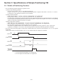
(1) Data sending procedure
Set data.
Send data (WV0004)
Set data length.
Send data length (WV0003)
Turned OFF by the application program.
Turned ON by the application program.
Send request (V0002)
Processing for sending
Send end (V0010)
Output only one scanning.
In case of sending error
Send status (WV0012)
Result of sending
Output only one scanning.
Send error (V0011)
After setting send data and its data length, turn send request (V0002) ON by the application program. Then FB detects the
rising edge to execute the processing for sending.
When sending has ended, send end flag (V0010) is turned ON (for only one scanning). If a send error has occurred, send end
(V0010) and send error (V0011) are turned ON (for only one scanning), and corresponding error code is output to send status
(WV0012) (“00” when ended normally).
(2) Send status list
No.
Result of sending
'00'
Normally ended
'01'
Send buffer has overflowed.
'40'
Data send time-out
Remarks
'90'
General purpose communication module disconnected.
'91'
SX bus send error
Not detected
'92'
SX bus receive error
Not detected
'A0'
Object port error
Specified port No. is neither 0 nor 1.
'A3'
Processing impossible because in code conversion mode
'A5'
Processing impossible because in loader mode.
'A6'
Processing impossible because self-diagnosis is being
executed.
Error detection on general purpose communication module
'C2'
Send buffer has overflowed.
Error detection on general purpose communication module
'C3'
Send data size over
Error detection on general purpose communication module
3-12
Section 3 Specifications of Communication FB
3-1 Non-procedural FB
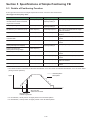
3-1-6 Data receiving
(1) Data receiving procedure
Communication ready (V0008)
Continuous receiving operation
Receive data (WV0005)
Receive data length (WV0016)
Receive end (V0013)
Output only one scanning.
In case of receive error
Receive error (V0014)
While the communication ready flag is turned ON, FB checks whether the data to be received exists or not continuously, and
when it exists, executes the operation for receiving. When a delimiter between data frames is detected, the received data and
the number of receive data bytes are stored in receive data (WV0005) and receive data length (WV0016), respectively, and the
receive end (V0013) flag is turned ON. The result of receiving is stored in receive status (WV0015). If a receive error has
occurred, receive end and receive error (V0014) are turned ON.
(2) Receiving status list
No.
Result of receiving
Remarks
'00'
Ended normally
'02'
Receive buffer has overflowed.
'42'
BCC error
'90'
General purpose communication module disconnected.
'91'
SX bus send error
'92'
SX bus receive error
'A0'
Object port error
'A3'
Processing impossible because in code conversion mode General purpose communication module detected an error.
'A5'
Processing impossible because in loader mode
General purpose communication module detected an error.
'A6'
Processing impossible because self-diagnosis is being
executed
General purpose communication module detected an error.
'C0'
Hardware error detected during receiving
(Parity error, Franming error, etc.)
General purpose communication module detected an error.
'C1'
Receive buffer has overflowed.
General purpose communication module detected an error.
General purpose communication module detected an error.
Note: Receiving conditions
The processing for receiving differs with the setting of parameter “Frame detection.”
None: Receiving completes when data is received.
Fixed length: Receiving completes when receive data reaches the specified number of receive data bytes.
Variable length: Receiving completes when the data in a range between start and end codes is received.
3-13
Section 3 Specifications of Communication FB
3-1 Non-procedural FB
3-1-7 RAS
RAS information in general purpose communication is assigned as shown in the following figure. RAS data is stored in the
position shown in the figure below from the start address of the device which is assigned to “RAS information parameter
(WV0007)” .
_Cfrpr, _Cfrpr2
_C_free
_Cfr252, _Cfr128, _Cfr64, _Cfr32
WM(WL)***+512 WM(WL)***+2560
WM(WL)***+1536
Port status
WM(WL)***+513 WM(WL)***+2561
WM(WL)***+1537
Status of general purpose
communication module
WM(WL)***+514 WM(WL)***+2562
WM(WL)***+1538
Send request count
WM(WL)***+515 WM(WL)***+2563
WM(WL)***+1539
Send end count
WM(WL)***+516 WM(WL)***+2564
WM(WL)***+1540
Receive count
WM(WL)***+517 WM(WL)***+2565
WM(WL)***+1541
Frame detection count
WM(WL)***+518 WM(WL)***+2566
WM(WL)***+1542
M_OPEN status
WM(WL)***+519 WM(WL)***+2567
WM(WL)***+1543
M_SEND status
WM(WL)***+520 WM(WL)***+2568
WM(WL)***+1544
M_RECEIVE status
WM(WL)***+521 WM(WL)***+2569
WM(WL)***+1545
M_SEND error count
WM(WL)***+522 WM(WL)***+2570
WM(WL)***+1546
M_RECEIVE error count
WM(WL)***+523 WM(WL)***+2571
WM(WL)***+1547
Reserved
WM(WL)***+524 WM(WL)***+2572
WM(WL)***+1548
Reserved
WM(WL)***+525 WM(WL)***+2573
WM(WL)***+1549
Reserved
WM(WL)***+526 WM(WL)***+2574
WM(WL)***+1550
Reserved
WM(WL)***+527 WM(WL)***+2575
WM(WL)***+1551
Reserved
WM(WL)***+528 WM(WL)***+2576
WM(WL)***+1552
Reserved
WM(WL)***+529 WM(WL)***+2577
WM(WL)***+1553
Reserved
WM(WL)***+530 WM(WL)***+2578
WM(WL)***+1554
Reserved
WM(WL)***+531 WM(WL)***+2579
WM(WL)***+1555
Reserved
Port status
Control data
General purpose communication module status
Error data
15 14 13 12 11 10 9 8 7 6 5 4 3 2 1 0
15 14 13 12 11 10 9 8 7 6 5 4 3 2 1 0
Mode switch(x8)
Mode switch(x4)
Mode switch(x2)
Mode switch(x1)
Reserved
Reserved
Reserved
Reserved
Reserved
Reserved
Reserved
Reserved
RS-485 station No.(x8)
RS-485 station No.(x4)
RS-485 station No.(x2)
RS-485 station No.(x1)
RS signal
CS signal
DR signal
ER signal
CD signal
CI sinnal
Initialization end
Reserved
Send error
Receive error
Framing error
Overrun
Oarity error
Reserved
Reserved
Reserved
3-14
Section 3 Specifications of Communication FB
3-2 FUJI General Purpose Inverter Procedure FB “_CfdFRN”
3-2-1 General
The “_CfdFRN” FB communicates data between the CPU module and FUJI FRENIC Series general purpose inverter using the
start-stop synchronization type transmission protocol. For more information about the detailed transmission parameters that
are necessary to control the FRENIC 5000 Series general purpose inverter, refer to the manual supplied with the inverter.
* “a” is suffixed to the name of the FB supporting array/structure.
Note: When using FBs supporting array/structure, use V2.2.3.0 or later version of Standard loader.
<FB functions>
1) Initialization of communication port function
Initializes the RS-485 port (the setting of transmission speed, data bit length, parity bit, etc.)
2) Data sending/receiving function
Sends data from an application program in the MICREX-SX series CPU module to general purpose inverter FRENIC 5000XXX
via the general purpose communication module, or outputs the data received via the general purpose communication module
to an application program.
3) Transmission condition monitoring function
Monitors data transmission condition and outputs error information if abnormal.
<Connecting method of “_CfdFRN”>
The connecting method between the general purpose communication module and FUJI FRENIC 5000 series general
purpose inverter must be “1:N connection” by RS-485 (2-wire system).
<FB operating conditions>
System configuration:
One FB is necessary for each communication port (RS-485) to be used. Communication with the inverters that are
connected to one RS-485 system is performed by one FB.
FUJI general purpose inverter may not be connected to the RS-232C port.
This FB cannot be used in the mode where RS-232C/RS-485 signal conversion is enabled for the general purpose
communication module.
Memory capacity:
Program area = Approx. 2.6k steps
Data memory capacity = User FB memory
Standard memory
System FB memory
: 376 words
: 854 words
: 90 words
Note 1: The above list for the memory capacity includes the area for the main body of inverter FB and those for sub-FBs that
are called from the inverter FB.
Note 2: The above list for standard memory and retain memory includes the memory capacity necessary for sending/receiving
data.
3-15
Section 3 Specifications of Communication FB
3-2 FUJI General Purpose Inverter Procedure FB “_CfdFRN”
3-2-2 Specifications for _CfdFRN
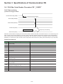
(1) FB format
_CfdFRN/_CfdFRNa
Open
OPEN
V1
OK
V12
Communication ready
Send request
S_REQ
V2
O_STS
WV13
Open status
Send station address
S_STN
WV3
R_END
V14
Receive end
Send command code
S_CMD
WV4
R_ERR
V15
Receive error
R_STS
WV16
Receive status
R_STN
WV17
Receive station address
R_ERCD
WV18
Receive error code
R_LEN
WV19
Number of receive data bytes
S_FNC
WV5
Send function code
Send function code
S_FNC
WV5
Number of send data bytes
S_LEN
WV6
Receive function code
R_FNC
WV7
R_FNC
WV7
Receive function code
Send text data
S_TXT
WV8
S_TXT
WV8
Send text data
Receive text data
R_TXT
WV9
R_TXT
WV9
Receive text data
Communication parameter
PARA
WV10
PARA
WV10
Communication parameter
RAS infomation
RAS
WV11
RAS
WV11
RAS infomation
3-16
Section 3 Specifications of Communication FB
3-2 FUJI General Purpose Inverter Procedure FB “_CfdFRN”
(2) Explanation of FB parameters
Parameter name
Data type
I/O
Description
Open
(OPEN)
V0001
BOOL
IN
ON: Sends the "communication parameters" to the general
purpose communication module to initialize communication.
When communication becomes possible, "communication
ready" turns ON.
OFF: Performs the processing for ending communication.
"Communication ready" turns OFF.
Send request
(S_REQ)
V0002
BOOL
IN
Starts to send data. When sending has ended, this needs to be
turned OFF by the application program.
Send station address
(S_STN)
WV0003 WORD
IN
Stores the address of the send station.
Send command code
(S_CMD)
WV0004 WORD
IN
Stores the send command code.
Send function code
(S_FNC)
WV0005 WORD
IN_OUT Stores the send function code.
* Occupies two words.
Number of send data bytes
(S_LEN)
WV0006 INT
IN
Receive function code
(R_FNC)
WV0007 WORD
IN_OUT Stores the receive function code.
* Occupies two words.
Send text data (S_TXT)
WV0008 WORD
IN_OUT Stores the send text data.
Receive text data (R_TXT)
WV0009 WORD
IN_OUT Stores the receive text data.
Communication parameter
(PARA)
WV0010 INT
IN_OUT Stores the initialization parameters.
RAS information (RAS)
WV0011 * Note 1.
IN_OUT Operating information of this FB.
Communication ready (OK)
V0012
OUT
Turns ON when initialization has ended normally to indicate that
the system is ready for sending/receiving data.
BOOL
Stores the number of send data bytes.
Open status (O_STS)
WV0013 WORD
OUT
2-digit hexadecimal code to indicate the result of initialization.
Receive end (R_END)
V0014
BOOL
OUT
Turns ON when receive ends.
Receive error (R_ERR)
V0015
BOOL
OUT
Turn ON if a receive error has occurred.
Receive status (R_STS)
WV0016 WORD
OUT
Code to indicate the result of receiving
Receive station address
(R_STN)
WV0017 WORD
OUT
Stores the address of the receive station.
Receive error code
(R_ERCD)
WV0018 WORD
OUT
Stores the receive error code.
OUT
Stores the number of receive data bytes.
Number of receive data bytes WV0019 INT
(R_LEN)
*Note 1:
Element name
Data type
Work area for sending
WORD
Work area for receiving
WORD
Receive buffer area
WORD
Send buffer area
WORD
RAS area
INT
* For more information about data type, refer to “Appendix 1.”
3-17
Section 3 Specifications of Communication FB
3-2 FUJI General Purpose Inverter Procedure FB “_CfdFRN”
<Send text data; format of the memory assigned to “WV0008”>
The memory that is assigned to WV0008 must be set (secured) as follows.
Specify the start address of the memory for WV0008.
Upper order
Start address
Lower order
WM(WL)****
Data 2
Data 1
WM(WL)****+1
Data 4
Data 3
WM(WL)****+31
Data 64
Data 63
<Receive text data; format of the memory assigned to “WV0009”>
The memory that is assigned to WV0009 must be set (secured) as follows.
Specify the start address of the memory for WV0009.
Upper order
Start address
Lower order
WM(WL)****
Data 2
Data 1
WM(WL)****+1
Data 4
Data 3
WM(WL)****+31
Data 64
Data 63
3-18
Section 3 Specifications of Communication FB
3-2 FUJI General Purpose Inverter Procedure FB “_CfdFRN”
<Communication parameter; format of the memory assigned to “WV0010”>
The memory that is assigned to WV0010 must be set (secured) as follows.
Specify the start address of the memory for WV0010.
Start address
WM(WL)***
General purpose communication
module station No.
WM(WL)***+1
Port No.
WM(WL)***+2
Message port No.
WM(WL)***+3
Reserved
WM(WL)***+4
Transmission speed
WM(WL)***+5
Data bit
WM(WL)***+6
Parity bit
WM(WL)***+7
Stop bit
WM(WL)***+8 to 15
Reserved
WM(WL)***+16
Response monitoring timer
WM(WL)***+17
Retry count
WM(WL)***+18 to 39
Reserved
<RAS information; format of the memory assigned to “WV0011”>
The memory that is assigned to WV0011 must be set (secured) as follows.
Specify the start address of the memory for WV0011.
Start address
WM(WL)****
Work area for sending
(256 words)
WM(WL)****+255
WM(WL)****+256
WM(WL)****+511
WM(WL)****+512
WM(WL)****+591
WM(WL)****+592
WM(WL)****+671
WM(WL)****+672
WM(WL)****+691
Work area for receiving
(256 words)
Receive buffer area
(80 words)
Send buffer area
(80 words)
RAS area
(20 words)
3-19
Section 3 Specifications of Communication FB
3-2 FUJI General Purpose Inverter Procedure FB “_CfdFRN”
3-2-3 Initialization
(1) Initialization parameters
In order to initialize (RS-485) communication ports which are to be used, it is necessary to set proper values for each
“communication parameter” item so as to match the communication specifications of the general purpose inverter. The table
below shows the setting contents of these parameters.
No.
Item
Description
0
General purpose communication Sets the station number of the general purpose communication module on the SX bus.
module station No.
1
Port No.
Designates an interface port on the general purpose communication module.
1: RS-485 port
2
Message port No.
Designates a port No. for sending/receiving message to/from a general purpose
communication module.
3
Reserved
Not used
4
Transmission speed
Designates the transmission speed.
0: 1200, 1: 2400, 2: 4800, 3: 9600, 4: 19200 bps
5
Data bit
Designates the data bit length. When "7" is selected, 7 bits make up one data; when
"8", 8 bits make up one data.
0: 7 bits (when ASCII code is used)
1: 8 bits (when EBCDIC code is used)
6
Parity bit
This is a bit which is added to data for the purpose of error detection. Designate the
proper one to match the setting of the device at the other end.
0: None, 1: Odd, 2: Even
7
Stop bit
This bit indicates the end of data. Designate the proper one to match the setting of the
device at the other end.
0: 1 bit, 2: 2 bits
8
:
15
Reserved
Not used
16
Response monitoring timer
The timer for monitoring during the period from when the CPU module (FB) sends a
send request to an external device until communication ends. This value can be set in
0.01-second steps.
Example: For 1 second, set this value to "100".
17
Retry count
In case of communication error, this designates how many times to retry communication.
18
:
39
Reserved
Not used
Note: No. in the above table is the number of the words from the start for communication parameter.
3-20
Section 3 Specifications of Communication FB
3-2 FUJI General Purpose Inverter Procedure FB “_CfdFRN”
(2) Initialization procedure
When the OPEN (V0001) parameter of FB is turned ON, communication parameters are transferred to the general purpose
communication module, which executes processing for initialization. If initialization is impossible due to a communication
parameter setting error or hardware error, FB outputs the corresponding error code to the OPEN Status (WV0013).
Turned ON by the application program.
OPEN request
(V0001)
Processing for initialization
Turned OFF by the application program.
Port closing operation
Communication ready
(V0012)
Note: OPEN signal shall be set to Always ON during data communication.
If initialization error has occurred
OPEN Status
(V0013)
00
Error status
(3) OPEN status list
No.
Result of initialization
Remarks
'00'
Ended normally
'01'
Transmission speed error
General purpose communication module detected an error.
'02'
Data bit length error
General purpose communication module detected an error.
'03'
Parity bit error
General purpose communication module detected an error.
'04'
Stop bit error
General purpose communication module detected an error.
'05'
Reserved
'06'
Reserved
'07'
Reserved
'3F'
Parameter modification error
'40'
Response monitoring timer value setting error
'41'
Retry count setting error
'42'
Reserved
'43'
Reserved
'44'
BCC code setting error
'80'
General purpose communication module station
No. setting error
'81'
Port No. setting error
'82'
Message port No. setting error
'93'
Open error
Initialization failed due to SX bus error
'94'
Open error
Initialization failed due to abnormality on general purpose
communication module
'A3'
Processing impossible because in code
conversion mode
General purpose communication module detected an error.
'A5'
Processing impossible because in loader mode
General purpose communication module detected an error.
'A6'
Processing impossible because self-diagnosis is
being executed
General purpose communication module detected an error.
Parameter modification error after OPEN
3-21
Section 3 Specifications of Communication FB
3-2 FUJI General Purpose Inverter Procedure FB “_CfdFRN”
3-2-4 Data sending/receiving
(1) Data sending/receiving procedure
Set send text data.
Send text data
(WV0008)
Set send station address.
Send station address
(WV0003)
Set send command code.
Send command code
(WV0004)
Set send function code.
Send function code
(WV0005)
Turned ON by the application program.
Turned OFF by the application program.
Send request (V0002)
Receive text data
(WV0009)
Receive station address
(WV0017)
Receive function code
(WV0007)
Receive error code
(WV0018)
Receive status
(WV0016)
Receive end (V0014)
In case of receive error
Output only one scanning
Receive error (V0015)
Send text data, send station address, send command code and send function code are set and then send request is turned
ON by the application program. FB detects the rising edge to execute the processing for sending.
When the send station address is for all stations (= 90), the receive end flag is automatically turned ON the moment sending
is completed (receive error flag is also turned ON if abnormal).
When the send station address is for one station ( = 90), the system automatically enters receiving waiting mode the moment
sending is completed, executing the processing for receiving. When the delimiter between frames is detected, the receive end
flag is automatically turned ON (receive error flag is also turned ON if abnormal).
3-22
Section 3 Specifications of Communication FB
3-2 FUJI General Purpose Inverter Procedure FB “_CfdFRN”
(2) Sending/receiving status list
No.
Result of sending
Remarks
'00'
Normally ended
'01'
Send buffer has overflowed.
'02'
Receive buffer has overflowed.
'40'
Data send time-out
'41'
Protocol response error
'42'
BCC error
'90'
General purpose communication module
disconnected.
'91'
SX bus send error
'92'
SX bus receive error
'A0'
Object port error
General purpose communication module detected an error.
'A3'
Processing impossible because in code
conversion mode
General purpose communication module detected an error.
'A5'
Processing impossible because in loader mode
General purpose communication module detected an error.
'A6'
Processing impossible because self-diagnosis is
being executed
General purpose communication module detected an error.
'C0'
Hardware error detected during receiving
General purpose communication module detected an error.
'C1'
Receive buffer has overflowed.
General purpose communication module detected an error.
'C2'
Send buffer has overflowed.
General purpose communication module detected an error.
'C3'
Send data size over
General purpose communication module detected an error.
Not detected
3-23
Section 3 Specifications of Communication FB
3-2 FUJI General Purpose Inverter Procedure FB “_CfdFRN”
3-2-5 RAS
RAS information in general purpose communication is assigned as shown in the following figure. RAS data is stored in the
position shown in the figure below from the start address of the device which is assigned to “RAS information parameter
(WV0011) .
WM(WL)***+672
Port status
WM(WL)***+673
Status of general purpose
communication module
WM(WL)***+674
Send request count
WM(WL)***+675
Send end count
WM(WL)***+676
Receive count
WM(WL)***+677
Frame detection count
WM(WL)***+678
M_OPEN status
WM(WL)***+679
M_SEND status
WM(WL)***+680
M_RECEIVE status
WM(WL)***+681
M_SEND error count
WM(WL)***+682
M_RECEIVE error count
WM(WL)***+683
Reserved
WM(WL)***+684
Reserved
WM(WL)***+685
Reserved
WM(WL)***+686
Reserved
WM(WL)***+687
Reserved
WM(WL)***+688
Reserved
WM(WL)***+689
Reserved
WM(WL)***+690
Reserved
WM(WL)***+691
Reserved
Port status
Control data
General purpose communication module status
Error data
15 14 13 12 11 10 9 8 7 6 5 4 3 2 1 0
15 14 13 12 11 10 9 8 7 6 5 4 3 2 1 0
Mode switch(x8)
Mode switch(x4)
Mode switch(x2)
Mode switch(x1)
Reserved
Reserved
Reserved
Reserved
Reserved
Reserved
Reserved
Reserved
RS-485 station No.(x8)
RS-485 station No.(x4)
RS-485 station No.(x2)
RS-485 station No.(x1)
RS signal
CS signal
DR signal
ER signal
CD signal
CI sinnal
Initialization end
Reserved
Send error
Receive error
Framing error
Overrun
Oarity error
Reserved
Reserved
Reserved
3-24
Section 3 Specifications of Communication FB
3-3 FUJI General Purpose Inverter Standard Communication (FGI-BUS)
Procedure FB “_CfdFVR”
3-3-1 General
The “_CfdFVR” FB communicates data between the CPU module and FUJI FVR Series general purpose inverter using the
“FGI-BUS” transmission protocol. For more information of the detailed transmission parameters that are necessary to control
the FVR Series general purpose inverter, refer to the manual supplied with the inverter.
* “a” is suffixed to the name of the FB supporting array/structure.
Note: When using FBs supporting array/structure, use V2.2.3.0 or later version of Standard loader.
<FB functions>
1) Initialization of communication port function
Initializes the RS-485 port (the setting of transmission speed, data bit length, parity bit, etc.)
2) Data sending/receiving function
Sends data from an application program in the MICREX-SX series CPU module to general purpose inverter (FVR) via the
general purpose communication module, or outputs the data received via the general purpose communication module to an
application program.
3) Transmission condition monitoring function
Monitors data transmission condition and outputs error information if abnormal.
<Connecting method of “_CfdFVR”>
The connecting method between the general purpose communication module and FUJI FVR series general purpose inverter
must be “1:N connection” by RS-485 (2-wire system).
<FB operating conditions>
System configuration:
One FB is necessary for each communication port (RS-485) to be used. Communication with the inverters that are
connected to one RS-485 system is performed by one FB.
FUJI general purpose inverter may not be connected to the RS-232C port.
This FB cannot be used in the mode where RS-232C/RS-485 signal conversion is enabled for the general purpose
communication module.
Memory capacity:
Program area = Approx. 2.7k steps
Data memory capacity = User FB memory
Standard memory
System FB memory
: 458 words
: 794 words
: 90 words
Note 1: The above list for the memory capacity includes the area for the main body of inverter procedure FB and those for subFBs that are called from the inverter procedure FB.
Note 2: The above list for standard memory and retain memory includes the memory capacity necessary for sending/receiving
data.
* FGI-BUS: Fuji Electric General Inverter’s Serial protocol
3-25
Section 3 Specifications of Communication FB
3-3 FUJI General Purpose Inverter Standard Communication (FGI-BUS)
Procedure FB “_CfdFVR”
3-3-2 Specifications for _CfdFVR
(1) FB format
_CfdFVR/_CfdFVRa
Open
OPEN
V1
OK
V11
Communication ready
Send request
S_REQ
V2
O_STS
WV12
Open status
Send station address
S_STN
WV3
R_END
V13
Receive end
Send command type
S_KND
WV4
R_ERR
V14
Receive error
R_STS
WV15
Receive status
R_STN
WV16
Receive station address
R_KND
WV17
Receive command type
R_ERCD
WV18
Receive error code
R_LEN
WV19
Number of receive data bytes
Send function code
R_FNC
WV5
R_FNC
WV5
Send function code
Receive function code
S_FNC
WV6
S_FNC
WV6
Receive function code
Send text data
S_TXT
WV7
S_TXT
WV7
Send text data
Receive text data
R_TXT
WV8
R_TXT
WV8
Receive text data
PARA
WV9
PARA
WV9
Communication parameter
RAS
WV10
RAS
WV10
RAS information
Communication parameter
RAS information
3-26
Section 3 Specifications of Communication FB
3-3 FUJI General Purpose Inverter Standard Communication (FGI-BUS)
Procedure FB “_CfdFVR”
(2) Explanation of FB parameters
Parameter name
Data type
I/O
Description
Open
(OPEN)
V0001
BOOL
IN
ON: Sends the "communication parameters" to the general
purpose communication module to initialize communication.
When communication becomes possible, "communication
ready" turns ON.
OFF: Performs the processing for ending communication.
"Communication ready" turns OFF.
Send request
(S_REQ)
V0002
BOOL
IN
Starts to send data. When sending has ended, this needs to be
turned OFF by the application program.
Send station address
(S_STN)
WV0003
WORD
IN
Stores the address of the send station.
Send command type
(S_KND)
WV0004
WORD
IN
Stores the send command type.
Receive function code
(R_FNC)
WV0005
WORD
IN_OUT Stores the receive function code.
* Occupies two words.
Send function code
(S_FNC)
WV0006
WORD
IN_OUT Stores the send function code.
* Occupies two words.
Send text data (S_TXT)
WV0007
WORD
IN_OUT Stores the send text data.
Receive text data (R_TXT)
WV0008
WORD
IN_OUT Stores the receive text data.
Communication parameter
(PARA)
WV0009
INT
IN_OUT Stores the initialization parameters.
RAS information
(RAS)
WV0010
* Note 1.
IN_OUT Operating information of this FB.
Communication ready
(OK)
V0011
BOOL
OUT
Turns ON when initialization has ended normally to indicate that
the system is ready for sending/receiving data.
Open status (O_STS)
WV0012
WORD
OUT
2-digit hexadecimal code to indicate the result of initialization.
Receive end (R_END)
V0013
BOOL
OUT
Turns ON when receive ends.
Receive error (R_ERR)
V0014
BOOL
OUT
Turn ON if a receive error has occurred.
Receive status (R_STS)
WV0015
WORD
OUT
Code to indicate the result of receiving
Receive station address
(R_STN)
WV0016
WORD
OUT
Stores the address of the receive station.
Receive command type
(R_KND)
WV0017
WORD
OUT
Stores the receive command type
Receive error code
(R_ERCD)
WV0018
WORD
OUT
Stores the receive error code.
Number of receive data
bytes
(R_LEN)
WV0019
INT
OUT
Stores the number of receive data bytes.
* Note 1
Element name
Data type
Work area for sending
WORD
Work area for receiving
WORD
Receive buffer area
WORD
Send buffer area
WORD
RAS area
INT
* For more information about data type, refer to “Appendix 1”.
3-27
Section 3 Specifications of Communication FB
3-3 FUJI General Purpose Inverter Standard Communication (FGI-BUS)
Procedure FB “_CfdFVR”
<Send text data; format of the memory assigned to “WV0007”>
The memory that is assigned to WV0007 must be set (secured) as follows.
Specify the start address of the memory for WV0007.
Upper order
Start address
Lower order
WM(WL)****
Data 2
Data 1
WM(WL)****+1
Data 4
Data 3
<Receive text data; format of the memory assigned to “WV0008”>
The memory that is assigned to WV0008 must be set (secured) as follows.
Specify the start address of the memory for WV0008.
Upper order
Start address
Lower order
WM(WL)****
Data 2
Data 1
WM(WL)****+1
Data 4
Data 3
3-28
Section 3 Specifications of Communication FB
3-3 FUJI General Purpose Inverter Standard Communication (FGI-BUS)
Procedure FB “_CfdFVR”
<Communication parameter; format of the memory assigned to “WV0009”>
The memory that is assigned to WV0009 must be set (secured) as follows.
Specify the start address of the memory for WV0009.
Start address
WM(WL)***
General purpose communication
module station No.
WM(WL)***+1
Port No.
WM(WL)***+2
Message port No.
WM(WL)***+3
Reserved
WM(WL)***+4
Transmission speed
WM(WL)***+5
Data bit
WM(WL)***+6
Parity bit
WM(WL)***+7
Stop bit
WM(WL)***+8 to 15
Reserved
WM(WL)***+16
Response monitoring timer
WM(WL)***+17
Retry count
WM(WL)***+18 to 39
Reserved
<RAS information; format of the memory assigned to “WV0010”>
The memory that is assigned to WV0010 must be set (secured) as follows.
Specify the start address of the memory for WV0010.
Start address
WM(WL)****
Work area for sending
(256 words)
WM(WL)****+255
WM(WL)****+256
WM(WL)****+511
WM(WL)****+512
WM(WL)****+591
WM(WL)****+592
WM(WL)****+671
WM(WL)****+672
WM(WL)****+691
Work area for receiving
(256 words)
Receive buffer area
(80 words)
Send buffer area
(80 words)
RAS area
(20 words)
3-29
Section 3 Specifications of Communication FB
3-3 FUJI General Purpose Inverter Standard Communication (FGI-BUS)
Procedure FB “_CfdFVR”
3-3-3 Initialization
(1) Initialization parameters
In order to initialize (RS-485) communication ports which are to be used, it is necessary to set proper values for each
“communication parameter” item so as to match the communication specifications of the FVR-11 series general purpose
inverter. The table below shows the setting contents of these parameters.
No.
Item
Description
0
General purpose communication Sets the station number of the general purpose communication module on the SX bus.
module station No.
1
Port No.
Designates an interface port on the general purpose communication module.
1: RS-485 port
2
Message port No.
Designates a port No. for sending/receiving message to/from a general purpose
communication module.
3
Reserved
Not used
4
Transmission speed
Designates the transmission speed.
0: 1200, 1: 2400, 2: 4800, 3: 9600, 4: 19200 bps
5
Data bit
Designates the data bit length. When "7" is selected, 7 bits make up one data; when
"8", 8 bits make up one data.
0: 7 bits
1: 8 bits
6
Parity bit
This is a bit which is added to data for the purpose of error detection. Designate the
proper one to match the setting of the device at the other end.
0: None, 1: Odd, 2: Even
7
Stop bit
This bit indicates the end of data. Designate the proper one to match the setting of the
device at the other end.
0: 1 bit, 2: 2 bits
8
:
15
Reserved
Not used
16
Response monitoring timer
The timer for monitoring during the period from when the CPU module (FB) sends a
send request to an external device until communication ends. This value can be set in
0.01-second steps.
Example: For 1 second, set this value to "100".
17
Retry count
In case of communication error, this designates how many times to retry communication.
18
:
39
Reserved
Not used
Note: No. in the above table is the number of the words from the start for communication parameter.
3-30
Section 3 Specifications of Communication FB
3-3 FUJI General Purpose Inverter Standard Communication (FGI-BUS)
Procedure FB “_CfdFVR”
(2) Initialization procedure
When the OPEN (V0001) parameter of FB is turned ON, communication parameters are transferred to the general purpose
communication module, which executes processing for initialization. If initialization is impossible due to a communication
parameter setting error or hardware error, FB outputs the corresponding error code to the OPEN Status (WV0012).
Turned ON by the application program.
OPEN request
(V0001)
Turned OFF by the application program.
Processing for initialization
Port closing operation
Communication ready
(V0011)
Note: OPEN signal shall be set to Always ON during data communication.
If initialization error has occurred
OPEN Status
(WV0012)
00
Error status
(3) OPEN status list
No.
Result of initialization
Remarks
'00'
Ended normally
'01'
Transmission speed error
General purpose communication module detected an error.
'02'
Data bit length error
General purpose communication module detected an error.
'03'
Parity bit error
General purpose communication module detected an error.
'04'
Stop bit error
General purpose communication module detected an error.
'3F'
Parameter modification error
Parameter modification error after OPEN
'40'
Response monitoring timer value setting error
'41'
Retry count setting error
'80'
General purpose communication module station
No. setting error
'81'
Portl No. setting error
'82'
Message port No. setting error
'93'
Open error
Initialization failed due to SX bus error
'94'
Open error
Initialization failed due to abnormality on general purpose
communication module
'A3'
Processing impossible because in code
conversion mode
General purpose communication module detected an error.
'A5'
Processing impossible because in loader mode
General purpose communication module detected an error.
'A6'
Processing impossible because self-diagnosis is
being executed
General purpose communication module detected an error.
3-31
Section 3 Specifications of Communication FB
3-3 FUJI General Purpose Inverter Standard Communication (FGI-BUS)
Procedure FB “_CfdFVR”
3-3-4 Data sending/receiving
(1) Data sending/receiving procedure
Set send text data.
Send text data
(WV0007)
Set send station address.
Send station address
(WV0003)
Set send command type.
Send command type
(WV0004)
Set send function code.
Send function code
(WV0005)
Turned ON by the application program.
Turned OFF by the application program.
Send request (V0002)
Receive text data
(WV0008)
Receive station address
(WV0016)
Received command type
(WV0017)
Receive function code
(WV0006)
Receive error code
(WV0018)
Receive status
(WV0015)
Receive end (V0013)
In case of receive error
Output only one scanning
Receive error (V0014)
Send text data, send station address, send command code and send function code are set and then send request is turned
ON by the application program. FB detects the rising edge to execute the processing for sending.
When the send station address is for all stations (= 99), the receive end flag is automatically turned ON the moment sending
is completed (receive error flag is also turned ON if abnormal).
When the send station address is for one station ( = 99), the system automatically enters receiving waiting mode the moment
sending is completed, executing the processing for receiving. When the delimiter between frames is detected, the receive end
flag is automatically turned ON (receive error flag is also turned ON if abnormal).
3-32
Section 3 Specifications of Communication FB
3-3 FUJI General Purpose Inverter Standard Communication (FGI-BUS)
Procedure FB “_CfdFVR”
(2) Sending/receiving status list
No.
Result of sending/receiving
'00'
Normally ended
'01'
Send buffer has overflowed.
'02'
Receive buffer has overflowed.
'40'
Data send time-out
Remarks
'41'
Protocol response error
'42'
BCC error
'90'
General purpose communication module
disconnected.
'91'
SX bus send error
'92'
SX bus receive error
'93'
NAK receive
'A0'
Object port error
General purpose communication module detected an error.
'A3'
Processing impossible because in code
conversion mode
General purpose communication module detected an error.
'A5'
Processing impossible because in loader mode
General purpose communication module detected an error.
'A6'
Processing impossible because self-diagnosis is
being executed
General purpose communication module detected an error.
'C0'
Hardware error detected during receiving
General purpose communication module detected an error.
'C1'
Receive buffer has overflowed.
General purpose communication module detected an error.
'C2'
Send buffer has overflowed.
General purpose communication module detected an error.
'C3'
Send data size over
General purpose communication module detected an error.
Not detected
3-33
Section 3 Specifications of Communication FB
3-3 FUJI General Purpose Inverter Standard Communication (FGI-BUS)
Procedure FB “_CfdFVR”
3-3-5 RAS
RAS information in general purpose communication is assigned as shown in the following figure. RAS data is stored in the
position shown in the figure below from the start address of the device which is assigned to “RAS information parameter
(WV0010) .
WM(WL)***+672
Port status
WM(WL)***+673
Status of general purpose
communication module
WM(WL)***+674
Send request count
WM(WL)***+675
Send end count
WM(WL)***+676
Receive count
WM(WL)***+677
Frame detection count
WM(WL)***+678
M_OPEN status
WM(WL)***+679
M_SEND status
WM(WL)***+680
M_RECEIVE status
WM(WL)***+681
M_SEND error count
WM(WL)***+682
M_RECEIVE error count
WM(WL)***+683
Reserved
WM(WL)***+684
Reserved
WM(WL)***+685
Reserved
WM(WL)***+686
Reserved
WM(WL)***+687
Reserved
WM(WL)***+688
Reserved
WM(WL)***+689
Reserved
WM(WL)***+690
Reserved
WM(WL)***+691
Reserved
Port status
Control data
General purpose communication module status
Error data
15 14 13 12 11 10 9 8 7 6 5 4 3 2 1 0
15 14 13 12 11 10 9 8 7 6 5 4 3 2 1 0
Mode switch(x8)
Mode switch(x4)
Mode switch(x2)
Mode switch(x1)
Reserved
Reserved
Reserved
Reserved
Reserved
Reserved
Reserved
Reserved
RS-485 station No.(x8)
RS-485 station No.(x4)
RS-485 station No.(x2)
RS-485 station No.(x1)
RS signal
CS signal
DR signal
ER signal
CD signal
CI sinnal
Initialization end
Reserved
Send error
Receive error
Framing error
Overrun
Oarity error
Reserved
Reserved
Reserved
3-34
Section 3 Specifications of Communication FB
3-4 Communication Protocol Included General Purpose Inverter Procedure
FB “_Cfvrpr”
3-4-1 General
The “_Cfvrpr” FB communicates data, using the “FGI-BUS”, between the CPU module and FUJI FVR Series general purpose
inverter. The “_Cfvrpr” FB performs part of the processing under the communication protocol in the firmware in the general
purpose communication module in order to reduce the number of program steps (see note).
For more information of the detailed transmission parameters that are necessary to control the FVR Series general purpose
inverter, refer to the manual supplied with the inverter.
Note: This FB can be used with V2536 or later version of general purpose communication module.
* “a” is suffixed to the name of the FB supporting array/structure.
Note: When using FBs supporting array/structure, use V2.2.3.0 or later version of Standard loader.
<FB functions>
1) Initialization of communication port function
Initializes the RS-485 port (the setting of transmission speed, data bit length, parity bit, etc.)
2) Data sending/receiving function
Sends data from an application program in the MICREX-SX series CPU module to general purpose inverter (FVR) via the
general purpose communication module, or outputs the data received via the general purpose communication module to an
application program.
3) Transmission condition monitoring function
Monitors data transmission condition and outputs error information if abnormal.
<Connecting method of “_Cfvrpr”>
The connecting method between the general purpose communication module and FUJI FVR series general purpose inverter
must be “1:N connection” by RS-485 (2-wire system).
<FB operating conditions>
System configuration:
One FB is necessary for each communication port (RS-485) to be used. The control of all the inverters that are connected to
one RS-485 system is performed by one FB.
FUJI general purpose inverter may not be connected to the RS-232C port.
This FB cannot be used in the mode where RS-232C/RS-485 signal conversion is enabled for the general purpose
communication module.
Memory capacity:
Program area = Approx. 1.6k steps
Data memory capacity = User FB memory
Standard memory
System FB memory
: 260 words
: 826 words
: 84 words
Note 1: The above list for the memory capacity includes the area for the main body of inverter procedure FB and those for subFBs that are called from the inverter procedure FB.
Note 2: The above list for standard memory and retain memory includes the memory capacity necessary for sending/receiving
data.
3-35
Section 3 Specifications of Communication FB
3-4 Communication Protocol Included General Purpose Inverter Procedure
FB “_Cfvrpr”
3-4-2 Specifications for _Cfvrpr
(1) FB format
_Cfvrpr/_Cfvrpra
Open
Send request
OPEN
V1
S_REQ
V2
OK
V8
Communication ready
O_STS
WV9
Open status
S_RUN
V10
Send run
R_END
V11
Receive end
R_ERR
V12
Receive error
R_STS
WV13
Receive status
R_STN
WV14
Receive station address
R_KND
WV15
Receive command type
R_ERCD
WV16
Receive error code
R_LEN
WV17
Number of receive data bytes
Receive function code
R_FNC
WV3
R_FNC
WV3
Receive function code
Send text data
S_TXT
WV4
S_TXT
WV4
Send text data
Receive text data
R_TXT
WV5
R_TXT
WV5
Receive text data
Communication parameter
PARA
WV6
PARA
WV6
Communication parameter
RAS information
RAS
WV7
RAS
WV7
RAS information
3-36
Section 3 Specifications of Communication FB
3-4 Communication Protocol Included General Purpose Inverter Procedure
FB “_Cfvrpr”
(2) Explanation of FB parameters
Parameter name
Data type
I/O
Description
Open
(OPEN)
V0001
BOOL
IN
ON: Sends the "communication parameters" to the general
purpose communication module to initialize communication.
When communication becomes possible, "communication
ready" turns ON.
OFF: Performs the processing for ending communication.
"Communication ready" turns OFF.
Send request
(S_REQ)
V0002
BOOL
IN
Starts to send data. When sending has ended, this needs to be
turned OFF by the application program.
Receive function code
(R_FNC)
WV0003 WORD
IN_OUT Stores the function type character and function No. of receive frame.
* Occupies two words.
Send text data (S_TXT)
WV0004 WORD
IN_OUT Stores the send text data.
Receive text data (R_TXT)
WV0005 WORD
IN_OUT Received text data is stored when the data of the station to which
the inverter responded is received by the general purpose
communication module. When multiple inverters are connected,
the application program judges, based on receive station address
(WV0014), from which station the data was sent.
* Occupies two words.
Communication parameter WV0006 WORD
(PARA)
IN_OUT Stores the initialization parameters.
RAS information (RAS)
IN_OUT Operating information of this FB.
WV0007 * Note 1.
Communication ready (OK) V0008
BOOL
OUT
Turns ON when initialization has ended normally to indicate that
the system is ready for sending/receiving data.
Open status (O_STS)
WV0009 WORD
OUT
2-digit hexadecimal code to indicate the result of initialization.
Send run (S_RUN)
V0010
BOOL
OUT
Turns ON while data is sent to all stations.
Receive end (R_END)
V0011
BOOL
OUT
Turns ON when receive ends.
Receive error
(R_ERR)
V0012
BOOL
OUT
Turns ON if a receive error has occurred.
V0012 does not turn ON while NAK is received from a remote
station because NAK signal is received normally. V0012 turns ON
only when data is not normally received due to no response or
BCC error, for example.
Receive status
(R_STS)
WV0013 WORD
OUT
Code to indicate the result of receiving.
In case of no response (or BCCerror), sending station code is
output to the receiving station address so that it can be known
which station did not respond.
Receive station address
(R_STN)
WV0014 WORD
OUT
Stores the address of the receive station.
Receive command type
(R_KND)
WV0015 WORD
OUT
Stores command type characters of received frame.
Receive error code
(R_ERCD)
WV0016 WORD
OUT
Stores the error code sent from inverter if NAK is received from
inverter.
Number of receive data
bytes
(R_LEN)
WV0017 INT
OUT
Stores the number of receive data bytes.
* Note 1
Element name
Data type
Work area for sending
WORD
Work area for receiving
WORD
Receive buffer area
WORD
RAS area
INT
* For more information about data type, refer to “Appendix 1”.
3-37
Section 3 Specifications of Communication FB
3-4 Communication Protocol Included General Purpose Inverter Procedure
FB “_Cfvrpr”
<Send text data; format of the memory assigned to “WV0004”>
The memory that is assigned to WV0004 must be set (secured) as follows.
Specify the start address of the memory for WV0004.
Start address
Upper order
Lower order
WM(WL)****
SOH
Total number of
data sending stations
WM(WL)****+1
Station number (the units digit)
Station number (the tens digit)
WM(WL)****+2
Command type character
ENQ
WM(WL)****+3
Function number (the tens digit)
Function type character
WM(WL)****+4
Added special data
Function number (the units digit)
WM(WL)****+5
Data 2
Data 1
WM(WL)****+6
Data 4
Data 3
WM(WL)****+7
SOH
ETX
WM(WL)****+8
Station number (the units digit)
Station number (the tens digit)
WM(WL)****+9
Command type character
ENQ
WM(WL)****+10
Data 2
Data 1
WM(WL)****+11
Data 4
Data 3
WM(WL)****+12
SOH
ETX
WM(WL)****+13
Station number (the units digit)
Station number (the tens digit)
WM(WL)****+14
Command type character
ENQ
WM(WL)****+15
00
ETX
WM(WL)****+217
00
00
Note: Send data is prepared for the standard frames (14 bytes each) for maximum 31 inverter stations that can be
connected plus one byte (= 218 words). The data shall be set such that unused areas become 0 (zero).
* Send data is prepared for all the inverter stations that are connected, but data is sent to or received from one station at a time
due to FB internal processing.
<Receive text data; format of the memory assigned to “WV0005”>
The memory that is assigned to WV0005 must be set (secured) as follows.
Specify the start address of the memory for WV0005.
Upper order
Start address
Lower order
WM(WL)****
Data 2
Data 1
WM(WL)****+1
Data 4
Data 3
3-38
Section 3 Specifications of Communication FB
3-4 Communication Protocol Included General Purpose Inverter Procedure
FB “_Cfvrpr”
<Communication parameter; format of the memory assigned to “WV0006”>
The memory that is assigned to WV0006 must be set (secured) as follows.
Specify the start address of the memory for WV0006.
Start address
WM(WL)***
General purpose communication
module station No.
WM(WL)***+1
Port No.
WM(WL)***+2
Message port No.1
WM(WL)***+3
Message port No.2
WM(WL)***+4
Transmission speed
WM(WL)***+5
Data bit
WM(WL)***+6
Parity bit
WM(WL)***+7
Stop bit
WM(WL)***+8 to 15
Reserved
WM(WL)***+16
Response monitoring timer
WM(WL)***+17
Retry count
WM(WL)***+18 to 39
Reserved
<RAS information; format of the memory assigned to “WV0007”>
The memory that is assigned to WV0007 must be set (secured) as follows.
Specify the start address of the memory for WV0007.
Start address
WM(WL)****
Work area for sending
(256 words)
WM(WL)****+255
WM(WL)****+256
WM(WL)****+511
WM(WL)****+512
WM(WL)****+532
Work area for receiving
(256 words)
Receive buffer area
(21 words)
WM(WL)****+533
WM(WL)****+552
Send buffer area
(20 words)
<List of receive error codes (WV0016)>
Error code
Name
Description
4A(h)
Format error
Data exceeded the specified range.
4B(h)
Command error
Unspecified command code was sent.
4E(h)
Function code error
Inexistent function code was requested.
4F(h)
Write inhibit
Write request was issued during operation to a write inhibited function or a
function that inhibits writing during operation.
Note: For more information, refer to the inverter specifications.
3-39
Section 3 Specifications of Communication FB
3-4 Communication Protocol Included General Purpose Inverter Procedure
FB “_Cfvrpr”
3-4-3 Initialization
(1) Initialization parameters
In order to initialize each individual port of the general purpose communication module, it is necessary to set values which
match the communication specifications of the object external device to the individual communication parameters. The table
below shows the setting contents of these parameters.
No.
Item
0
General purpose communication Sets the station number of the general purpose communication module on the SX bus.
module station No.
1
Port No.
Designates an interface port on the general purpose communication module.
1: RS-485 port
Message port No. 1
Designates a port No. for sending/receiving message to/from a general purpose
communication module. (1 to 127)
Note: Avoid designating a port No. which is already used for sending/receiving
messages to/from other module.
3
Message port No. 2
Designates a port No. for sending/receiving message to/from a general purpose
communication module. (1 to 127)
Note: Avoid designating message port No. 1 or a port No. which is already used for
sending/receiving messages to/from other module.
4
Transmission speed
Designates the transmission speed.
0: 1200, 1: 2400, 2: 4800, 3: 9600, 4: 19200, 5: 38400, 6: 57600, 7: 76800,
8: 115200, 90: 300, 91:600 bps
5
Data bit
Designates the data bit length. When "7" is selected, 7 bits make up one data; when
"8", 8 bits make up one data.
0: 7 bits
1: 8 bits
6
Parity bit
This is a bit which is added to data for the purpose of error detection. Designate the
proper one to match the setting of the device at the other end.
0: None, 1: Odd, 2: Even
7
Stop bit
This bit indicates the end of data. Designate the proper one to match the setting of the
device at the other end.
0: 1 bit, 2: 2 bits
8
:
15
Reserved
2
Description
Not used
16
Response monitoring timer
The timer for monitoring during the period from when the CPU module (FB) sends data
to the inverter via the general purpose communication module until a response is
returned. This value can be set in 0.01-second steps.
Example: For 1 second, set this value to "100". Up to 327.67 seconds can be set.
17
Retry count
Designates how many times to retry communication. Range: 1 to 32767
18
:
39
Reserved
Not used
Note: Nos. 0 to 7 are the basic transmission parameters, and their setting cannot be changed during operation. The setting of
parameter Nos. 16 and 17 can be changed during operation.
3-40
Section 3 Specifications of Communication FB
3-4 Communication Protocol Included General Purpose Inverter Procedure
FB “_Cfvrpr”
(2) Initialization procedure
When the OPEN (V0001) parameter of FB is turned ON, communication parameters are transferred to the general purpose
communication module, which executes processing for initialization. If initialization is impossible due to a communication
parameter setting error or hardware error, FB outputs the corresponding error code to the OPEN Status (WV0009).
Turned ON by the application program.
OPEN request
(V0001)
Processing for initialization
Turned OFF by the application program.
Port closing operation
Communication ready
(V0008)
Note: OPEN signal shall be set to Always ON during data communication.
If initialization error has occurred
OPEN Status
(WV0009)
00
Error status
(3) OPEN status list
No.
Result of initialization
Remarks
'00'
Ended normally
'01'
Transmission speed error
General purpose communication module detected an error.
'02'
Data bit length error
General purpose communication module detected an error.
'03'
Parity bit error
General purpose communication module detected an error.
'04'
Stop bit error
General purpose communication module detected an error.
'3F'
Parameter modification error
Parameter modification error after OPEN
'40'
Response monitoring timer value setting error
When negative
'41'
Retry count setting error
When negative
'80'
General purpose communication module station
No. setting error
'81'
Portl No. setting error
'82'
Message port No. setting error
'93'
Open error
Initialization failed due to SX bus error
'94'
Open error
Initialization failed due to abnormality on general purpose
communication module
'A3'
Processing impossible because in code
conversion mode
General purpose communication module detected an error.
'A5'
Processing impossible because in loader mode
General purpose communication module detected an error.
'A6'
Processing impossible because self-diagnosis is
being executed
General purpose communication module detected an error.
3-41
Section 3 Specifications of Communication FB
3-4 Communication Protocol Included General Purpose Inverter Procedure
FB “_Cfvrpr”
3-4-4 Data sending/receiving
(1) Data sending/receiving procedure
The send data for all stations is set as a batch.
Send text data
(WV0004)
Turned ON by the application program.
Turned OFF by the application program.
Send request (V0002)
Send data for 1st station
Send data for 2nd station
Receive data for 2nd station
Receive data for 1st station
Receive end (V0011)
Turned ON for
one scan cycle
Turned ON for
one scan cycle
Receive error (V0012)
The send text data for all the stations is set as a batch, and send request is turned ON by the application program. The FB
sends the data to the 1st station and sets receive status (WV0013), receive station address (WV0014), receive command type
(WV0015) and receive function code (WV0003) when response data is received from the inverter on the 1st station. Then
receive end flag (V0011) is turned ON for one scan cycle. During the next scan cycle, communication with the 2nd station
inverter is started. When response data is received from the 2nd station after the data is sent to the 2nd station, receive status
(WV0013), receive station address (WV0014), receive command type (WV0015) and receive function code (WV0003) are
overwritten, and receive end flag (V0011) is turned ON again for one scan cycle.
Therefore, the setting shall be made such that the processing for receiving is started when receive end flag is turned ON.
3-42
Section 3 Specifications of Communication FB
3-4 Communication Protocol Included General Purpose Inverter Procedure
FB “_Cfvrpr”
(2) Sending/receiving status list (WV0013)
No.
Result of sending/receiving
Remarks
'00'
Normally ended
'01'
Send buffer has overflowed.
'02'
Receive buffer has overflowed.
'40'
Data send time-out
'41'
Protocol response error
'42'
BCC error
'43'
No vaild data
'44'
Previous send data sending
'90'
General purpose communication module
disconnected.
'91'
SX bus send error
'92'
SX bus receive error
'A0'
Object port error
General purpose communication module detected an error.
'A3'
Processing impossible because in code
conversion mode
General purpose communication module detected an error.
'A5'
Processing impossible because in loader mode
General purpose communication module detected an error.
'A6'
Processing impossible because self-diagnosis is
being executed
General purpose communication module detected an error.
'C0'
Hardware error detected during receiving
General purpose communication module detected an error.
'C1'
Receive buffer has overflowed.
General purpose communication module detected an error.
'C2'
Send buffer has overflowed.
General purpose communication module detected an error.
'C3'
Send data size over
General purpose communication module detected an error.
If the respense of remote station could not normally be
received, the address of the remote station is output to receive
station address (WV0014).
Not detected
3-43
Section 3 Specifications of Communication FB
3-4 Communication Protocol Included General Purpose Inverter Procedure
FB “_Cfvrpr”
3-4-5 RAS
RAS information in general purpose communication is assigned as shown in the following figure. RAS data is stored in the
position shown in the figure below from the start address of the device which is assigned to “RAS information parameter
(WV0007) .
WM(WL)***+533
Port status
WM(WL)***+534
Status of general purpose
communication module
WM(WL)***+535
Send request count
WM(WL)***+536
Send end count
WM(WL)***+537
Receive count
WM(WL)***+538
Frame detection count
WM(WL)***+539
M_OPEN status
WM(WL)***+540
M_SEND status
WM(WL)***+541
M_RECEIVE status
WM(WL)***+542
M_SEND error count
WM(WL)***+543
M_RECEIVE error count
WM(WL)***+544
Reserved
WM(WL)***+545
Reserved
WM(WL)***+546
Reserved
WM(WL)***+547
Reserved
WM(WL)***+548
Reserved
WM(WL)***+549
Reserved
WM(WL)***+550
Reserved
WM(WL)***+551
Reserved
WM(WL)***+552
Reserved
Port status
Control data
Note: Send end count is incremented by one when
the sending of data to all stations is completed.
General purpose communication module status
Error data
15 14 13 12 11 10 9 8 7 6 5 4 3 2 1 0
15 14 13 12 11 10 9 8 7 6 5 4 3 2 1 0
Mode switch(x8)
Mode switch(x4)
Mode switch(x2)
Mode switch(x1)
Reserved
Reserved
Reserved
Reserved
Reserved
Reserved
Reserved
Reserved
RS-485 station No.(x8)
RS-485 station No.(x4)
RS-485 station No.(x2)
RS-485 station No.(x1)
RS signal
CS signal
DR signal
ER signal
CD signal
CI sinnal
Initialization end
Reserved
Send error
Receive error
Framing error
Overrun
Oarity error
Reserved
Reserved
Reserved
3-44
Section 3 Specifications of Communication FB
3-5 FUJI Temperature Controller Procedure FB “_CfdPYX”
3-5-1 General
The “_CfdPYX” FB communicates data between the CPU module and FUJI PYX or PYH series temperature controller using the
start-stop synchronization type transmission protocol. For more information of the detailed transmission parameters that are
necessary to control the PYX or PYH series temperature controller, refer to the manual for the corresponding temperature
controller.
* “a” is suffixed to the name of the FB supporting array/structure.
Note: When using FBs supporting array/structure, use V2.2.3.0 or later version of Standard loader.
<FB functions>
1) Initialization of communication port function
Initializes communication port to be used (the setting of transmission speed, data bit length, parity bit, etc.)
2) Data sending/receiving function
Sends data from an application program in the MICREX-SX series CPU module to FUJI PYX or PYH series temperature
controller via the general purpose communication module, or outputs the data received via the general purpose communication
module to an application program.
3) Transmission condition monitoring function
Monitors data transmission condition and outputs error information if abnormal.
<Connecting method of “_CfdFRN”>
The connecting method between the general purpose communication module and FUJI PYX or PYH series temperature
controller must be “1:N connection” by RS-485 (2-wire system).
<FB operating conditions>
System configuration:
One FB is necessary for each communication port (RS-485) to be used. Communication with all the temperature controllers
that are connected to one RS-485 system is performed by one FB.
This FB cannot be used in the mode where RS-232C/RS-485 signal conversion is enabled for the general purpose
communication module.
Memory capacity:
Program area = Approx. 2.2k steps
Data memory capacity = User FB memory
Standard memory
System FB memory
: 400 words
: 818 words
: 98 words
Note 1: The above list for the memory capacity includes the area for the main body of the temperature controller procedure FB
and those for sub-FBs that are called from the temperature controller procedure FB.
Note 2: The above list for standard memory and retain memory includes the memory capacity necessary for sending/receiving
data.
3-45
Section 3 Specifications of Communication FB
3-5 FUJI Temperature Controller Procedure FB “_CfdPYX”
3-5-2 Specifications for _CfdPYX
(1) FB format
_CfdPYX/_CfdPYXa
Open
OPEN
V1
OK
V11
Communication ready
Send request
S_REQ
V2
O_STS
WV12
Open status
Transmission keyword (sending)
S_TFW
WV3
R_END
V13
Receive end
Send data area designation 1
S_DADR1
WV4
R_ERR
V14
Receive error
Send data area designation 2
S_DADR2
WV5
R_STS
WV15
Receive status
Send data area designation 3
S_DADR3
WV6
R_STN
WV16
Transmission keyword (receiving)
R_DADR1
WV17
Receive data area designation 1
R_DADR2
WV18
Receive data area designation 2
R_DADR3
WV19
Receive data area designation 3
Send data
S_DAT
WV7
S_DAT
WV7
Send data
Receive data
R_DAT
WV8
R_DAT
WV8
Receive data
PARA
WV9
PARA
WV9
Communication parameter
RAS
WV10
RAS
WV10
RAS information
Communication parameter
RAS information
3-46
Section 3 Specifications of Communication FB
3-5 FUJI Temperature Controller Procedure FB “_CfdPYX”
(2) Explanation of FB parameters
Parameter name
Data type
I/O
Description
Open
(OPEN)
V0001
BOOL
IN
ON: Sends the "communication parameters" to the general
purpose communication module to initialize communication.
When communication becomes possible, "communication
ready" turns ON.
OFF: Performs the processing for ending communication.
"Communication ready" turns OFF.
Send request
(S_REQ)
V0002
BOOL
IN
Starts to send data. When sending has ended, this needs to be
turned OFF by the application program.
Transmission keyword
(sending) (S_TFW)
WV0003
WORD
IN
Designates transmission keyword. There are 6 types of
transmission keyword: polling, selecting, control, positive
acknowledge1, positive acknowledge 2, and negative
acknowledge.
Send data area
WV0004
designation 1 (S_DADR1)
WORD
IN
Designates the data area for station No., file No. and extended
station No.
Send data area
WV0005
designation 2 (S_DADR2)
WORD
IN
Designates the data area for extended file No. and data length.
However, when transmission keyword is "control", this becomes
the command code area.
Send data area
WV0006
designation 3 (S_DADR3)
WORD
IN
Designates the data area for the start address of file, command
code and negative acknowledge cause data.
Send data (S_DAT)
WV0007
WORD
IN_OUT Stores send data.
Receive data (R_DAT)
WV0008
WORD
IN_OUT Stores received data.
Communication parameter WV0009
(PARA)
INT
IN_OUT Stores the initialization parameters.
RAS information
(RAS)
WV0010
* Note 1.
IN_OUT Operating information of this FB.
Communication ready
(OK)
V0011
BOOL
OUT
Turns ON when initialization has ended normally to indicate that
the system is ready for sending/receiving data.
Open status (O_STS)
WV0012
WORD
OUT
2-digit hexadecimal code to indicate the result of initialization.
Receive end (R_END)
V0013
BOOL
OUT
Turns ON when receive ends.
Receive error (R_ERR)
V0014
BOOL
OUT
Turn ON if a receive error has occurred.
Receive status (R_STS)
WV0015
WORD
OUT
Code to indicate the result of receiving
Transmission keyword
(receiving) (R_TFW)
WV0016
WORD
OUT
Stores transmission keyword for receiving.
Receive data area
WV0017
designation 1 (R_DADR1)
WORD
OUT
Designates receive data area.
Receive data area
WV0018
designation 2 (R_DADR2)
WORD
OUT
Designates receive data area.
Receive data area
WV0019
designation 3 (R_DADR3)
WORD
OUT
Designates receive data area.
* Note 1
Element name
Data type
Work area for sending
WORD
Work area for receiving
WORD
Receive buffer area
WORD
Send buffer area
WORD
Parameter area
INT
RAS area
INT
* For more information about data type, refer to “Appendix 1”.
3-47
Section 3 Specifications of Communication FB
3-5 FUJI Temperature Controller Procedure FB “_CfdPYX”
<Send text data; format of the memory assigned to “WV0007”>
The memory that is assigned to WV0007 must be set (secured) as follows.
Specify the start address of the memory for WV0007.
Upper order
Start address
Lower order
WM(WL)****
Data 2
Data 1
WM(WL)****+1
Data 4
Data 3
WM(WL)****+15
Data 32
Data 31
<Receive text data; format of the memory assigned to “WV0008”>
The memory that is assigned to WV0008 must be set (secured) as follows.
Specify the start address of the memory for WV0008.
Upper order
Start address
Lower order
WM(WL)****
Data 2
Data 1
WM(WL)****+1
Data 4
Data 3
WM(WL)****+15
Data 32
Data 31
3-48
Section 3 Specifications of Communication FB
3-5 FUJI Temperature Controller Procedure FB “_CfdPYX”
<Communication parameter; format of the memory assigned to “WV0009”>
The memory that is assigned to WV0009 must be set (secured) as follows.
Specify the start address of the memory for WV0009.
Start address
WM(WL)***
General purpose communication
module station No.
WM(WL)***+1
Port No.
WM(WL)***+2
Message port No.
WM(WL)***+3 to 15
Reserved
WM(WL)***+16
Response monitoring timer
WM(WL)***+17
Retry count
WM(WL)***+18 to 39
Reserved
<RAS information; format of the memory assigned to “WV0010”>
The memory that is assigned to WV0010 must be set (secured) as follows.
Specify the start address of the memory for WV0010.
Start address
WM(WL)****
WM(WL)****+255
WM(WL)****+256
Work area for sending
(256 words)
Work area for receiving
(256 words)
WM(WL)****+511
WM(WL)****+512
WM(WL)****+591
Receive buffer area
(80 words)
WM(WL)****+592
WM(WL)****+671
WM(WL)****+672
WM(WL)****+711
WM(WL)****+712
WM(WL)****+731
Send buffer area
(80 words)
Parameter area
(40 words)
RAS area
(20 words)
3-49
Section 3 Specifications of Communication FB
3-5 FUJI Temperature Controller Procedure FB “_CfdPYX”
3-5-3 Initialization
(1) Initialization parameters
In order to initialize (RS-485) communication ports which are to be used, it is necessary to set proper values for each
“communication parameter” item so as to match the communication specifications of the FUJI temperature controller. The
table below shows the setting contents of these parameters.
No.
Item
Description
0
General purpose communication Sets the station number of the general purpose communication module on the SX bus.
module station No.
1
Port No.
Designates an interface port on the general purpose communication module.
1: RS-232C port
0: RS-485 port
2
Message port No.
Designates a port No. for sending/receiving message to/from a general purpose
communication module.
3
:
15
Reserved
16
Response monitoring timer
The timer for monitoring during the period from when the CPU module sends a send
request to a device until communication ends.
Normally set this value to "100" (one second) (in 0.01-second steps).
17
Retry count
In case of communication error, this designates how many times to retry communication.
18
:
39
Reserved
Not used. Set 0 (zero) for the data.
Not used. Set 0 (zero) for the data.
(2) Initialization procedure
When the OPEN (V0001) parameter of FB is turned ON, communication parameters are transferred to the general purpose
communication module, which executes processing for initialization. If initialization is impossible due to a communication
parameter setting error or hardware error, FB outputs the corresponding error code to the OPEN Status (WV0012).
Turned ON by the application program.
OPEN request (Note)
(V0001)
Turned OFF by the application program.
Processing for initialization
Port closing operation
Communication ready
(V0011)
Note: OPEN signal shall be kept ON during data communication
If initialization error has occurred
OPEN Status
(WV0012)
“00”
“Error status”
3-50
Section 3 Specifications of Communication FB
3-5 FUJI Temperature Controller Procedure FB “_CfdPYX”
(3) OPEN status list
No.
Result of initialization
Remarks
'00'
Ended normally
'08'
RS-485 mode setting error
General purpose communication module detected an error.
'3F'
Parameter modification error
Parameter modification error after OPEN
'40'
Response monitoring timer value setting error
'41'
Retry count setting error
'80'
General purpose communication module station
No. setting error
'81'
Portl No. setting error
'82'
Message port No. setting error
'93'
Open error
Initialization failed due to SX bus error
'94'
Open error
Initialization failed due to abnormality on general purpose
communication module
'A3'
Processing impossible because in
code conversion mode.
General purpose communication module detected an error.
'A5'
Processing impossible because in loader mode.
General purpose communication module detected an error.
'A6'
Processing impossible because self-diagnosis is
being executed.
General purpose communication module detected an error.
3-51
Section 3 Specifications of Communication FB
3-5 FUJI Temperature Controller Procedure FB “_CfdPYX”
3-5-4 Data sending/receiving
(1) Data sending/receiving procedure
Set data.
Send data
(WV0007)
Set transmission keyword (sending)
Transmission keyword (sending)
(WV0003)
Set send data area designation 1
Send data area designation 1
(WV0004)
Set send data area designation 2
Send data area designation 2
(WV0005)
Set send data area designation 3
Send data area designation 3
(WV0006)
Turned ON by the application program.
Turned OFF by the application program.
Send request (V0002)
Receive data
(WV0008)
Transmission keyword (receiving)
(WV0016)
Receive data area designation 1
(WV0017)
Receive data area designation 2
(WV0018)
Receive data area designation 3
(WV0019)
Receive status
(WV0015)
Receive end (V0013)
In case of receive error
Output only one scanning
Receive error (V0014)
Send data, transmission keyword for sending, send data area designation 1, send data area designation 2 and send data
area designation 3 are set and then send request is turned ON by the application program. The FB detects the rising edge to
execute the processing for sending. When the processing for sending is completed, the FB automatically comes in receiving
waiting mode, executing the processing for receiving.
When the processing for sending and receiving has completed, received data, transmission keyword for receiving, receive
data area designation 1, receive data area designation 2 and receive data area designation 3 are stored, and then the receive
end flag is set ON (for only one pulse). In case of transmission error, both end flag and receive error flag are set ON (for only
one pulse).
3-52
Section 3 Specifications of Communication FB
3-5 FUJI Temperature Controller Procedure FB “_CfdPYX”
(2) Sending/receiving status list
No.
Result of sending/receiving
Remarks
'00'
Normally ended
'01'
Reserved
'02'
Send buffer has overflowed.
'40'
Data send time-out
'41'
Protocol response error
'42'
BCC error
'90'
General purpose communication module
disconnected.
'91'
SX bus send error
'92'
SX bus receive error
'A0'
Object port error
General purpose communication module detected an error.
'A3'
Processing impossible because in code
conversion mode.
General purpose communication module detected an error.
'A5'
Processing impossible because in loader mode.
General purpose communication module detected an error.
'A6'
Processing impossible because self-diagnosis is
being executed.
General purpose communication module detected an error.
'C0'
Hardware error detected during receiving
General purpose communication module detected an error.
'C1'
Receive buffer has overflowed.
General purpose communication module detected an error.
'C2'
Send buffer has overflowed.
General purpose communication module detected an error.
'C3'
Send data size over
General purpose communication module detected an error.
Not detected
3-53
Section 3 Specifications of Communication FB
3-5 FUJI Temperature Controller Procedure FB “_CfdPYX”
3-5-5 RAS
RAS information in general purpose communication is assigned as shown in the following figure. RAS data is stored in the
position shown in the figure below from the start address of the device which is assigned to “RAS information parameter
(WV0010) .
WM(WL)***+712
Port status
WM(WL)***+713
Status of general purpose
communication module
WM(WL)***+714
Send request count
WM(WL)***+715
Send end count
WM(WL)***+716
Receive count
WM(WL)***+717
Frame detection count
WM(WL)***+718
M_OPEN status
WM(WL)***+719
M_SEND status
WM(WL)***+720
M_RECEIVE status
WM(WL)***+721
M_SEND error count
WM(WL)***+722
M_RECEIVE error count
WM(WL)***+723
Reserved
WM(WL)***+724
Reserved
WM(WL)***+725
Reserved
WM(WL)***+726
Reserved
WM(WL)***+727
Reserved
WM(WL)***+728
Reserved
WM(WL)***+729
Reserved
WM(WL)***+730
Reserved
WM(WL)***+731
Reserved
Port status
Control data
General purpose communication module status
Error data
15 14 13 12 11 10 9 8 7 6 5 4 3 2 1 0
15 14 13 12 11 10 9 8 7 6 5 4 3 2 1 0
Mode switch(x8)
Mode switch(x4)
Mode switch(x2)
Mode switch(x1)
Reserved
Reserved
Reserved
Reserved
Reserved
Reserved
Reserved
Reserved
RS-485 station No.(x8)
RS-485 station No.(x4)
RS-485 station No.(x2)
RS-485 station No.(x1)
RS signal
CS signal
DR signal
ER signal
CD signal
CI sinnal
Initialization end
Reserved
Send error
Receive error
Framing error
Overrun
Oarity error
Reserved
Reserved
Reserved
3-54
Section 3 Specifications of Communication FB
3-6 FUJI Bar Code Reader Procedure FB “_CfdPK”
3-6-1 General
The “_CfdPK” FB communicates data between the CPU module and FUJI PK2 series bar code reader using the start-stop
synchronization type transmission protocol. For more information of the detailed transmission parameters that are necessary
to control FUJI bar code reader, refer to the manual supplied with the PK2 series bar code reader.
* “a” is suffixed to the name of the FB supporting array/structure.
Note: When using FBs supporting array/structure, use V2.2.3.0 or later version of Standard loader.
<FB functions>
1) Initialization of communication port function
Initialize the RS-232C port (the setting of transmission speed, data bit length, parity bit, etc.)
2) Data sending/receiving function
Sends data from an application program in the MICREX-SX series CPU module to the FUJI bar code reader via the general
purpose communication module, or outputs the data received via the general purpose communication module to an
application program.
3) Transmission condition monitoring function
Monitors data transmission condition and outputs error information if abnormal.
<Connecting method of “_CfdFRN”>
The connecting method between the general purpose communication module and FUJI PK2 series bar code reader must be
“1:1 connection” by RS-232C.
<FB operating conditions>
System configuration:
One FB is necessary for each communication port (RS-232C) to be used.
FUJI PK2 series bar code reader may not be connected to the RS-485 port.
Memory capacity:
Program area = Approx. 3.3k steps
Data memory capacity = User FB memory
Standard memory
System FB memory
: 478 words
: 846 words
: 90 words
Note 1: The above list for the memory capacity includes the area for the main body of the bar code reader procedure FB and
those for sub-FBs that are called from the bar code reader procedure FB.
Note 2: The above list for standard memory and retain memory includes the memory capacity necessary for sending/receiving
data.
3-55
Section 3 Specifications of Communication FB
3-6 FUJI Bar Code Reader Procedure FB “_CfdPK”
3-6-2 Specifications for _CfdPK
(1) FB format
_CfdPK/_CfdPKa
Open
OPEN
V1
OK
V8
Communication ready
Send request
S_REQ
V2
O_STS
WV9
Open status
Number of send data bytes
S_LEN
WV3
S_END
V10
Send end
S_ERR
V11
Send error
S_STS
WV12
Send status
R_END
V13
Receive end
R_ERR
V14
Receive error
R_STS
WV15
Receive status
R_LEN
WV16
Number of receive data bytes
Send data
S_DAT
WV4
S_DAT
WV4
Send data
Receive data
R_DAT
WV5
R_DAT
WV5
Receive data
Communication parameter
PARA
WV6
PARA
WV6
Communication parameter
RAS information
RAS
WV7
RAS
WV7
RAS information
3-56
Section 3 Specifications of Communication FB
3-6 FUJI Bar Code Reader Procedure FB “_CfdPK”
(2) Explanation of FB parameters
Parameter name
Data type
I/O
Description
Open
(OPEN)
V0001
BOOL
IN
ON: Sends the "communication parameters" to the general
purpose communication module to initialize
communication. When communication becomes possible,
"communication ready" turns ON.
OFF: Performs the processing for ending communication.
"Communication ready" turns OFF.
Send request
(S_REQ)
V0002
BOOL
IN
Starts to send data. When sending has ended, this needs to
be turned OFF by the application program.
Number of send data bytes
(S_LEN)
WV0003 INT
IN
Stores the number of bytes of send data.
Send data (S_DAT)
WV0004 WORD
IN_OUT Stores send data.
Receive data (R_DAT)
WV0005 WORD
IN_OUT Stores received data.
Communication parameter
(PARA)
WV0006 INT
IN_OUT Stores the initialization parameters.
RAS information
(RAS)
WV0007 * Note 1
IN_OUT Operating information of this FB.
Communication ready (OK)
V0008
OUT
Turns ON when initialization has ended normally to indicate that
the system is ready for sending/receiving data.
Open status (O_STS)
WV0009 WORD
OUT
2-digit hexadecimal code to indicate the result of initialization.
Send end (S_END)
V0010
BOOL
OUT
Turns ON when sending has completed.
Send error (S_ERR)
V0011
BOOL
OUT
Turns ON if a send error has occurred.
Send status (S_STS)
WV0012 WORD
OUT
Code to indicate the result of sending.
Receive end (R_END)
V0013
BOOL
OUT
Turns ON when receive has completed.
Receive error (R_ERR)
V0014
BOOL
OUT
Turn ON if a receive error has occurred.
Receive status (R_STS)
WV0015 WORD
OUT
Code to indicate the result of receiving
OUT
Stores the number of bytes of receive data.
BOOL
Number of receive data bytes WV0016 INT
(R_LEN)
* Note 1
Element name
Data type
Work area for sending
WORD
Work area for receiving
WORD
Receive buffer area
WORD
Send buffer area
WORD
Parameter area
INT
RAS area
INT
* For more information about data type, refer to “Appendix 1”.
3-57
Section 3 Specifications of Communication FB
3-6 FUJI Bar Code Reader Procedure FB “_CfdPK”
<Send text data; format of the memory assigned to “WV0004”>
The memory that is assigned to WV0004 must be set (secured) as follows.
Specify the start address of the memory for WV0004.
Upper order
Start address
Lower order
WM(WL)****
Data 2
Data 1
WM(WL)****+1
Data 4
Data 3
WM(WL)****+31
Data 64
Data 63
<Receive text data; format of the memory assigned to “WV0005”>
The memory that is assigned to WV0005 must be set (secured) as follows.
Specify the start address of the memory for WV0005.
Upper order
Start address
Lower order
WM(WL)****
Data 2
Data 1
WM(WL)****+1
Data 4
Data 3
WM(WL)****+31
Data 64
Data 63
3-58
Section 3 Specifications of Communication FB
3-6 FUJI Bar Code Reader Procedure FB “_CfdPK”
<Communication parameter; format of the memory assigned to “WV0006”>
The memory that is assigned to WV0006 must be set (secured) as follows.
Specify the start address of the memory for WV0006.
Start address
WM(WL)***
General purpose communication
module station No.
WM(WL)***+1
Port No.
WM(WL)***+2
Message port No.
WM(WL)***+3
Reserved
WM(WL)***+4
Transmission speed
WM(WL)***+5
Data bit
WM(WL)***+6
Parity bit
WM(WL)***+7
Stop bit
WM(WL)***+8 to 15
Reserved
WM(WL)***+16
Response monitoring timer
WM(WL)***+17
Start code
WM(WL)***+18
End code
WM(WL)***+19
Transmission procedure
WM(WL)***+20
Retry count
WM(WL)***+21
BCC designation
WM(WL)***+22 to 39
Reserved
<RAS information; format of the memory assigned to “WV0007”>
The memory that is assigned to WV0007 must be set (secured) as follows.
Specify the start address of the memory for WV0007.
Start address
WM(WL)****
WM(WL)****+255
WM(WL)****+256
Work area for sending
(256 words)
Work area for receiving
(256 words)
WM(WL)****+511
WM(WL)****+512
WM(WL)****+591
Receive buffer area
(80 words)
WM(WL)****+592
WM(WL)****+671
WM(WL)****+672
WM(WL)****+711
WM(WL)****+712
WM(WL)****+731
Send buffer area
(80 words)
Parameter area
(40 words)
RAS area
(20 words)
3-59
Section 3 Specifications of Communication FB
3-6 FUJI Bar Code Reader Procedure FB “_CfdPK”
3-6-3 Initialization
(1) Initialization parameters
In order to initialize (RS-232C) communication ports which are to be used, it is necessary to set proper values for each
“communication parameter” item so as to match the communication specifications of the PK2 series bar code reader. The
table below shows the setting contents of these parameters.
No.
Item
Description
0
General purpose communication Sets the station number of the general purpose communication module on the SX bus.
module station No.
1
Port No.
Designates an interface port on the general purpose communication module.
0: RS232C port
2
Message port No.
Designates a port No. for sending/receiving message to/from a general purpose
communication module.
3
Reserved
Not used
4
Transmission speed
Designates the transmission speed.
0: 1200, 1: 2400, 2: 4800, 3: 9600, 4: 19200 bps
5
Data bit
Designates the data bit length. When "7" is selected, 7 bits make up one data; when
"8", 8 bits make up one data.
0: 7 bits
1: 8 bits
6
Parity bit
This is a bit which is added to data for the purpose of error detection. Designate the
proper one to match the setting of the device at the other end.
0: None, 1: Odd, 2: Even
7
Stop bit
This bit indicates the end of data. Designate the proper one to match the setting of the
device at the other end.
0: 1 bit, 2: 2 bits
8
:
15
Reserved
16
Response monitoring timer
The timer for monitoring during the period from when the CPU module sends a send
request to a device until communication ends.
Normally set this value to "100" (one second) (in 0.01-second steps).
17
Start code
Designates the start code of transmission command.
0: None, 1: STX
18
End code
Designates the end code of transmission command.
0: CR, 1: LF, 2: CR/LF, 3: ETX, 4: ETXCRF, 5: ETX/LF, 6: ETX/CR/LF
19
Transmission procedure
Designates transmission procedure.
0: Non-procedural
Receives the end data simply as ead by the bar code reader.
1: ACK/NAK procedure
Sends ACK when the data read by the bar code reader is received normally; NAK if
a receiving error occurred.
20
Retry count
In case of communication error, this designates how many times to retry communication.
21
BCC designation
Sets whether or not to add horizontal parity for checking text data transmission error.
0: No, 1: Yes
22
:
39
Reserved
Not used
Not used
3-60
Section 3 Specifications of Communication FB
3-6 FUJI Bar Code Reader Procedure FB “_CfdPK”
(2) Initialization procedure
When the OPEN (V0001) parameter of FB is turned ON, communication parameters are transferred to the general purpose
communication module, which executes processing for initialization. If initialization is impossible due to a communication
parameter setting error or hardware error, FB outputs the corresponding error code to the OPEN Status (WV0009).
Turned ON by the application program.
OPEN request
(V0001)
Turned OFF by the application program.
(Note)
Processing for initialization
Port closing operation
Communication ready
(V0008)
Note: OPEN signal shall be set to Always ON during data communication.
If initialization error has occurred
OPEN Status
(WV0009)
00
Error status
(3) OPEN status list
No.
Result of initialization
Remarks
'00'
Ended normally
'01'
Transmission speed error
General purpose communication module detected an error.
'02'
Data bit length error
General purpose communication module detected an error.
'03'
Parity bit error
General purpose communication module detected an error.
'04'
Stop bit error
General purpose communication module detected an error.
'3F'
Parameter modification error
Parameter modification error after OPEN
'40'
Response monitoring timer value setting error
'41'
Retry count setting error
'42'
Start code setting error
'43'
End code setting error
'44'
BCC code setting error
'45'
Retry count setting error
'80'
General purpose communication module station
No. setting error
'81'
Port No. setting error
'82'
Message port No. setting error
'93'
Open error
Initialization failed due to bus error.
'94'
Open error
Initialization failed due to abnormality on general purpose
communication module
'A3'
Processing impossible because in code
conversion mode.
General purpose communication module detected an error.
'A5'
Processing impossible because in loader mode.
General purpose communication module detected an error.
'A6'
Processing impossible because self-diagnosis is
being executed.
General purpose communication module detected an error.
3-61
Section 3 Specifications of Communication FB
3-6 FUJI Bar Code Reader Procedure FB “_CfdPK”
3-6-4 Data sending
(1) Data sending procedure
Sets send data and send data length.
Send data (WV0004)
Number of send data bytes (WV0003)
Turned ON by the application program.
Turned OFF by the application program.
Send request (V0002)
Processing for sending
Send end (V0010)
Output only one scanning.
In case of sending error
Send error (V0011)
After setting send data and its data length, turn send request (V0002) ON by the application program. Then FB detects the
rising edge to execute the processing for sending.
When sending has ended, send end flag (V0010) is turned ON (for only one pulse). If a send error has occurred, send end
(V0010) and send error (V0011) are turned ON (for only one pulse), and corresponding error code is output to send status
(WV0012) (“00” when ended normally).
(2) Sending status list
No.
Result of sending
Remarks
'00'
Normally ended
'01'
Send buffer has overflowed.
'42'
BBC error
'90'
General purpose communication module
disconnected.
'91'
SX bus send error
'92'
SX bus receive error
Not detected
'A0'
Object port error
Specified port No. is neither 0 nor 1.
'A3'
Processing impossible because in code
conversion mode
'A5'
Processing impossible because in loader mode
'A6'
Processing impossible because self-diagnosis is
being executed
Error detection on general purpose communication module
'C0'
Hardware error detected during receiving
Error detection on general purpose communication module
'C1'
Receive buffer has overflowed.
Error detection on general purpose communication module
'C2'
Send buffer has overflowed.
Error detection on general purpose communication module
'C3'
Send data size over
Error detection on general purpose communication module
Not detected
3-62
Section 3 Specifications of Communication FB
3-6 FUJI Bar Code Reader Procedure FB “_CfdPK”
3-6-5 Data receiving
(1) Data receiving procedure
Communication ready (V0008)
Continuous receiving operation
Receive data (WV0005)
Receive status (WV0015)
Receive end (V0013)
In case of receive error
Output only one scanning.
Receive error (V0014)
While the communication ready flag is turned ON, FB checks whether the data to be received exists or not continuously, and
when it exists, execute the operation for receiving. When a delimiter between data frames is detected, the received data is
stored, and the receive end (V0013) flag is turned ON (for only one pulse). The result of receiving is stored in receive status
(WV0015). If a receive error has occurred, receive end (V0013) and receive error (V0014) are turned ON (for only one pulse).
(2) Receiving status list
No.
Result of sending/receiving
Remarks
'00'
Ended normally
'02'
Receive buffer has overflowed.
'41'
Protocol response error
'42'
BCC error
'90'
General purpose communication module
disconnected.
'91'
SX bus send error
'92'
SX bus receive error
'A0'
Object port error
General purpose communication module detected an error.
'A3'
Processing impossible because in code
conversion mode.
General purpose communication module detected an error.
'A5'
Processing impossible because in loader mode.
General purpose communication module detected an error.
'A6'
Processing impossible because self-diagnosis is
being executed.
General purpose communication module detected an error.
'C0'
Hardware error detected during receiving
(Parity error, Franming error, etc.)
General purpose communication module detected an error.
'C1'
Receive buffer has overflowed.
General purpose communication module detected an error.
'C2'
Send buffer has overflowed.
General purpose communication module detected an error.
'C3'
Number of send data over
General purpose communication module detected an error.
3-63
Section 3 Specifications of Communication FB
3-6 FUJI Bar Code Reader Procedure FB “_CfdPK”
3-6-6 RAS
RAS information in general purpose communication is assigned as shown in the following figure. RAS data is stored in the
position shown in the figure below from the start address of the device which is assigned to “RAS information parameter
(WV0007) .
WM(WL)***+712
Port status
WM(WL)***+713
Status of general purpose
communication module
WM(WL)***+714
Send request count
WM(WL)***+715
Send end count
WM(WL)***+716
Receive count
WM(WL)***+717
Frame detection count
WM(WL)***+718
M_OPEN status
WM(WL)***+719
M_SEND status
WM(WL)***+720
M_RECEIVE status
WM(WL)***+721
M_SEND error count
WM(WL)***+722
M_RECEIVE error count
WM(WL)***+723
Reserved
WM(WL)***+724
Reserved
WM(WL)***+725
Reserved
WM(WL)***+726
Reserved
WM(WL)***+727
Reserved
WM(WL)***+728
Reserved
WM(WL)***+729
Reserved
WM(WL)***+730
Reserved
WM(WL)***+731
Reserved
Port status
Control data
General purpose communication module status
Error data
15 14 13 12 11 10 9 8 7 6 5 4 3 2 1 0
15 14 13 12 11 10 9 8 7 6 5 4 3 2 1 0
Mode switch(x8)
Mode switch(x4)
Mode switch(x2)
Mode switch(x1)
Reserved
Reserved
Reserved
Reserved
Reserved
Reserved
Reserved
Reserved
RS-485 station No.(x8)
RS-485 station No.(x4)
RS-485 station No.(x2)
RS-485 station No.(x1)
RS signal
CS signal
DR signal
ER signal
CD signal
CI sinnal
Initialization end
Reserved
Send error
Receive error
Framing error
Overrun
Oarity error
Reserved
Reserved
Reserved
3-64
Section 3 Specifications of Communication FB
3-7 MODBUS Procedure FB “_C_modm”
3-7-1 General
The “_C_modm” FB communicates data between the CPU module and FA device equipped with MODBUS interface. While
there are MODBUS master and slave devices, this FB makes MICREX-SX a master device and communicates data with
MODBUS slave devices. MODBUS master device may not be connected to this FB. Determine which functions to use
according to the specifications for the MODBUS slave devices to be connected.
* “a” is suffixed to the name of the FB supporting array/structure.
Note: When using FBs supporting array/structure, use V2.2.3.0 or later version of Standard loader.
<FB functions>
1) Initialization of communication port function
Initialize communication ports to be used (the setting of transmission speed, data bit length, parity bit, etc.)
2) Data sending/receiving function
Sends data from an application program in the MICREX-SX series CPU module to MODBUS devices via the general purpose
communication module, or outputs the data received via the general purpose communication module to an application
program.
3) Transmission condition monitoring function
Monitors data transmission condition and outputs error information if abnormal.
4) Supported function codes
This FB supports the following functions. For the data format for individual function, refer to “3-7-2 (4) Function codes”.
Function code Function
Function code Function
01
Coil (output) reading
06
Retain register writing (1 word)
02
Input bit reading
08
Diagnosis (see note)
03
Retain register reading
0F
Forcible ON/OFF (multiple bits)
04
Input register reading
10
Retain register writing (multiple words)
05
Forcible ON/OFF (1 bit)
Note: For more information of diagnosis, refer to MODBUS specification.
<Connecting method of “_C_modm”>
The connecting method between the general purpose communication module and MODBUS devices, 1:1 connection by RS232C and 1:N connection by RS-485 (2-wire system) are available.
<FB operating conditions>
System configuration:
One FB is necessary for each communication port (RS-232C, RS485) to be used. One FB is used to communicate data with
the MODBUS devices that are connected to one port.
This FB can be used with V2536 or later version of the general purpose communication module.
Memory capacity:
Program area = Approx. 4.2k steps
Data memory capacity = User FBs memory
Standard memory
System FBs memory
: 424 words
: 2386 words
: 90 words
Note 1: The above list for the memory capacity includes the area for the main body of MODBUS procedure FB and those for
sub-FBs that are called from the MODBUS procedure FB.
Note 2: The above list for standard memory and retain memory includes the memory capacity necessary for sending/receiving
data.
3-65
Section 3 Specifications of Communication FB
3-7 MODBUS Procedure FB “_C_modm”
3-7-2 Specifications for _C_modm
(1) Communication specifications
Item
Specification
Transmission speed
300/600/1200/2400/4800/9600/19200/38400/57600/76800/115200 bps
Data bits
8 bits (Fixed)
Parity bit
None/odd/even
Stop bits
Selected from 1/2 bits
DCE
Selected from DTE/DCE/modem DTE mode
Modem DTE mode: Turn CD ON when receiving
Signal control
Signal flow
control
DTE mode
ER: always ON
DCE mode
DR: always ON
DTE mode
Off RS: always ON; Sending: unconditional
On RS: ON during sending; Sending: when CS is ON
DCE mode
Off CS: always ON; Sending: unconditional
On CS: ON when RS is ON; Sending: when ER is ON
XON/XOFF control
The prerequisite of XON/XOFF flow control is that XON or XOFF does not appear on the data.
RS-485 mode
Selected from 4-wire/2-wire
Code conversion
None (Fixed)
Error check
CRC16 (Upper order/Lower order) (Fixed)
Transmission timer value
x10ms
3-66
Section 3 Specifications of Communication FB
3-7 MODBUS Procedure FB “_C_modm”
(2) FB format
_C_modm/_C_modma
Open request
OPEN
V1
Send request
S_REQ
V2
O_STS
WV13
Open status
Slave station No.
STN_NO_I
WV3
R_END
V14
Receive end
Function code
F_CODE_I
WV4
R_ERR
V15
Receive error
Start address
ADD_I
WV5
R_STS
WV16
Receive status
Data length
LEN_I
WV6
STN_NO_O
WV17
Slave station No.
LEN2_I
WV7
F_CODE_O
WV18
Function code
Number of bytes
OK
V12
Communication ready
ADD_O
WV19
Start address
LEN_O
WV20
Data length
LEN2_O
WV21
Number of bytes
Send data
S_DAT
WV8
S_DAT
WV8
Send data
Receive data
R_DAT
WV9
R_DAT
WV9
Receive data
Communication parameter
PARA
WV10
PARA
WV10
Communication parameter
RAS infomation
RAS
WV11
RAS
WV11
RAS infomation
3-67
Section 3 Specifications of Communication FB
3-7 MODBUS Procedure FB “_C_modm”
(3) Explanation of FB parameters
Parameter name
Data type
I/O
Description
Open
(OPEN)
V0001
BOOL
IN
ON: Sends the "communication parameters" to the general
purpose communication module to initialize communication.
When communication becomes possible, "communication
ready" turns ON.
OFF: Performs the processing for ending communication.
"Communication ready" turns OFF.
Send request
(S_REQ)
V0002
BOOL
IN
Starts to send data. When sending has ended, this needs to be
turned OFF by the application program.
Slave station No. (Query)
(STN_NO_I)
WV0003 INT
IN
Designates destination slave station No.
Function code (Query)
(F_CODE_I)
WV0004 WORD
IN
Designates which MODBUS function to use. This code is set in
the lower order byte. Example: WORD#16#0010
Start address (Query)
(ADD_I)
WV0005 WORD
IN
Designates the start address of the data that becomes the object
of reading or writing operation. For diagnosis (08), diagnosis
code is input.
Set data in the following format:
F
8 7
Upper order
Data length (Query)
(LEN_I)
WV0006 WORD
IN
Designates the size (the number of bits or words) of read data or
write data. Some functions do not use this parameter. In such
case, set this item to "0000h".
Set data in the following format:
F
8 7
Upper order
Number of bytes
(LEN2_I)
WV0007 WORD
IN
0
Lower order
0
Lower order
Designates the number of bytes of write data when multiple bits
(0F) or multiple words (10) are to be written. For other functions,
set this item to "0000h".
Set data in the following format.
F
8 7
Upper order
0
Lower order
Send data (S_DAT)
WV0008 WORD
IN_OUT Stores send data.
For data reading or diagnosis, the data are all set to 0 (zero).
Receive data (R_DAT)
WV0009 WORD
IN_OUT Stores received data.
Communication parameter
(PARA)
WV0010 INT
IN_OUT Stores the initialization parameters.
Refer to "3-7-3 Initialization" for details.
RAS information (RAS)
WV0011 * Note 1.
IN_OUT Operating information of this FB.
Communication ready
(OK)
V0012
OUT
Turns ON when initialization has ended normally to indicate that
the system is ready for sending/receiving data.
Open status (O_STS)
WV0013 WORD
OUT
2-digit hexadecimal code to indicate the result of initialization.
Receive end (R_END)
V0014
BOOL
OUT
Turns ON when receiving has completed normally.
Receive error (R_ERR)
V0015
BOOL
OUT
Turn ON if a receive error has occurred.
Receive status (R_STS)
WV0016 WORD
OUT
Code to indicate the result of receiving
Slave station No.
(Response)
(STN_NO_O)
WV0017 INT
OUT
Remote slave station number is output.
Function code (Response)
(F_CODE_O)
WV0018 WORD
OUT
Start address (Response)
(ADD_O)
WV0019 WORD
OUT
According to the request from this FB, the value of "function code",
"start address", "data length" and "the number of bytes" that are
included in the response data sent form slave device are output.
They are output in the same format as is set in the input (Query).
Data length (Response)
(LEN_O)
WV0020 WORD
OUT
No. of bytes (Response)
(LEN2_O)
WV0021 WORD
OUT
BOOL
3-68
Section 3 Specifications of Communication FB
3-7 MODBUS Procedure FB “_C_modm”
* Note 1
Element name
Data type
Work area for sending
WORD
Work area for receiving
WORD
Receive buffer area
WORD
Send buffer area
WORD
RAS area
INT
CRC area
WORD
* For more information about data type, refer to “Appendix 1.”
<Send data; format of the memory assigned to “WV0008”>
The memory that is assigned to WV0008 must be set (secured) as follows.
Specify the start address of the memory for WV0008.
Upper order
Start address
Lower order
WM(WL)****
Data 2
Data 1
WM(WL)****+1
Data 4
Data 3
Data 512
Data 511
WM(WL)****+255
<Receive data; format of the memory assigned to “WV0009”>
The memory that is assigned to WV0009 must be set (secured) as follows.
Specify the start address of the memory for WV0009.
Upper order
Start address
Lower order
WM(WL)****
Data 2
Data 1
WM(WL)****+1
Data 4
Data 3
Data 512
Data 511
WM(WL)****+255
3-69
Section 3 Specifications of Communication FB
3-7 MODBUS Procedure FB “_C_modm”
<Communication parameter; format of the memory assigned to “WV0010”>
The memory that is assigned to WV0010 must be set (secured) as follows.
Specify the start address of the memory for WV0010.
Start address
WM(WL)***
General purpose communication
module station No.
WM(WL)***+1
Port No.
WM(WL)***+2
Message port No.1
WM(WL)***+3
Reserved
WM(WL)***+4
Transmission speed
WM(WL)***+5
Reserved
WM(WL)***+6
Parity bit
WM(WL)***+7
Stop bit
WM(WL)***+8
DCE designation
WM(WL)***+9
ER/DR signal control
WM(WL)***+10
Signal flow control
WM(WL)***+11
XON/XOFF control
WM(WL)***+12
RS-485 mode
WM(WL)***+13 to 34
WM(WL)***+35
WM(WL)***+36 to 39
Reserved
Response monitoring timer
Reserved
<RAS information; format of the memory assigned to “WV0011”>
The memory that is assigned to WV0011 must be set (secured) as follows.
Specify the start address of the memoryor WV0011.
Start address
WM(WL)****
WM(WL)****+255
WM(WL)****+256
WM(WL)****+511
WM(WL)****+512
WM(WL)****+1023
Work area for sending
(256 words)
Work area for receiving
(256 words)
Receive buffer area
(512 words)
WM(WL)****+1024
WM(WL)****+1535
WM(WL)****+1536
Send buffer area
(512 words)
RAS area
(20 words)
WM(WL)****+1555
WM(WL)****+1556
WM(WL)****+1811
CRC area
(256 words)
3-70
Section 3 Specifications of Communication FB
3-7 MODBUS Procedure FB “_C_modm”
(4) Function code
1) Coil reading (code: 01) / Input bit reading (code: 02)
Reads the status of the output/input bit of a slave device. The format of request message and response message is as follows:
FB terminals
Request message
Response message
Slave station No. (WV0003) J
Slave station No.
Slave station No.
Function code (WV0004) J
Start address (WV0005) J
Data length (WV0006) J
FB terminals
J Slave station No. (WV0017)
J Function code (WV0018)
Function code
Function code
Start address (upper order)
Number of bytes of read data
Start address (lower order)
Read data (lower order)
Data length (upper order)
Read data (upper order)
Data length (lower order)
Read data (lower order)
CRC (lower order)
Read data (upper order)
CRC (upper order)
:
J Data length (WV0020)
J Receive data (WV0009)
CRC (lower order)
CRC (upper order)
Notes:
1) In case of abnormal response, 80hex is added to function code (WV0018).
2) Function 01/02 does not use the number of bytes (WV0007). Set “H0000” for the WV0007 terminal. Similarly, all the
variables that are connected to the “send data” terminal (WV0008) shall be set to zero.
3) CRC is automatically calculated and added to the data by this FB.
4) The number of bytes of read data is stored in the upper order byte of data length (WV0020).
5) When read data is received, its upper- and lower-order bytes are reversed as shown below.
Receive data (WV0009)
Offset address with respect to the designated start address.
+7
+6
+5
+4
+3
+2
+1
+0
+15
+14
+13
+12
+11
+10
+9
+8
+23
+22
+21
+20
+19
+18
+17
+16
+31
+30
+29
+28
+27
+26
+25
+24
3-71
Section 3 Specifications of Communication FB
3-7 MODBUS Procedure FB “_C_modm”
2) Retain register reading (code: 03)/Input register reading (code: 04)
Reads the status of the input bit of a slave device. The format of request message and response message is as follows:
FB terminals
Request message
Response message
Slave station No. (WV0003) J
Slave station No.
Slave station No.
Function code
Function code
Start address (upper order)
Number of bytes of read data
Start address (lower order)
Read data (upper order)
Data length (upper order)
Read data (lower order)
Data length (lower order)
Read data (upper order)
CRC (lower order)
Read data (lower order)
CRC (upper order)
:
Function code (WV0004) J
Start address (WV0005) J
Data length (WV0006) J
FB terminals
J Slave station No. (WV0017)
J Function code (WV0018)
J Data length (WV0020)
J Receive data (WV0009)
CRC (lower order)
CRC (upper order)
Notes:
1) In case of abnormal response, 80hex is added to function code (WV0018).
2) Function 03/04 does not use the number of bytes (WV0007). Set “H0000” for the WV0007 terminal. Similarly, all the
variables that are connected to the “send data” terminal (WV0008) shall be set to zero.
3) CRC is automatically calculated and added to the data by this FB.
4) Request message specifies the number of words by data length (WV0006); response message stores is as the number
of bytes of read data in the upper order byte of data length (WV0020).
5) Read data is received in the order of upper byte and lower order byte, as shown below. Therefore, word data can be
accessed in units of word as it is.
Receive data (WV0009) J
Upper order byte
Lower order byte
Upper order byte
Lower order byte
Upper order byte
Lower order byte
:
:
3) Forcible ON/OFF (1 bit) (code:05)
Forcibly sets ON/OFF a bit (coil) that is designated by a slave station. The format of request message and response message
is as follows:
FB terminals
Request message
Response message
Slave station No. (WV0003) J
Slave station No.
Slave station No.
Function code (WV0004) J
Start address (WV0005) J
Send data (WV0008) J
Function code 05h
Function code 05h
Coil address (upper order)
Coin address (upper order)
Coil address (lower order)
Coil address (lower order)
FFh(ON)/00h(OFF) (upper order)
FFh(ON)/00h(OFF) (lower order)
00h (lower order)
00h (lower order)
CRC (lower order)
CRC (lower order)
CRC (upper order)
CRC (upper order)
FB terminals
J Slave station No. (WV0017)
J Function code (WV0018)
J Data length (WV0020)
J Receive data (WV0009)
Notes:
1) In case of abnormal response, 80hex is added to function code (WV0018).
2) Function 05 does not use data length (WV0006) and the number of bytes (WV0007). Set “H0000” for each parameter.
3) CRC is automatically calculated and added to the data by this FB.
4) Forcible ON command sets HFF00 for the start word of send data. Forcible OFF command sets H0000.
3-72
Section 3 Specifications of Communication FB
3-7 MODBUS Procedure FB “_C_modm”
4) Retain register writing (1 word) (code: 06)
Writes data in the register (1 word) that is designated by a slave device. The format of requst message and response
message is as follows:
FB terminals
Request message
Response message
Slave station No. (WV0003) J
Slave station No.
Slave station No.
Function code 06h
Function code 06h
Register address (upper order)
Register address (upper order)
Register address (lower order)
Register address (lower order)
Write data (upper order)
Write data (upper order)
Write data (lower order)
Write data (lower order)
CRC (lower order)
CRC (lower order)
CRC (upper order)
CRC (upper order)
Function code (WV0004) J
Start address (WV0005) J
Send data (WV0008) J
FB terminals
J Slave station No. (WV0017)
J Function code (WV0018)
J Data length (WV0020)
J Receive data (WV0009)
Notes:
1) In case of abnormal response, 80hex is added to function code (WV0018).
2) Function 06 does not use the data length (WV0006) or the number of bytes (WV0007). Set “H0000” for each parameter.
3) CRC is automatically calculated and added to the data by this FB.
4) For send data, set the data that is to be written in the start word. Other data shall be set to all zero.
5) Forcible ON/OFF (multiple bits) (code: 0F)
Forcibly sets ON/OFF a bit (coil) that is designated by a slave station. The format of request message and response message
is as follows:
FB terminals
Request message
Slave station No. (WV0003) J
Data length (WV0006) J
Slave station No.
Function code 10h
Start address (upper order)
Start address (upper order)
Start address (lower order)
Start address (lower order)
No. of written words (upper order)
No. of written words (upper order)
No. of written words (lower order)
No. of written words (lower order)
Number of bytes (WV0007) J
Send data (WV0008) J
FB terminals
J Slave station No. (WV0017)
Slave station No.
Function code 10h
Function code (WV0004) J
Start address (WV0005) J
Response message
Number of bytes
CRC (lower order)
Write data (upper order)
CRC (upper order)
J Function code (WV0018)
J Start address (WV0019)
J Data length (WV0020)
Write data (lower order)
:
CRC (lower order)
CRC (upper order)
Notes:
1) In case of abnormal response, 80hex is added to function code (WV0018).
2) CRC is automatically calculated and added to the data by this FB.
3) Write data shall be set with upper- and lower-order bytes reversed, as shown below:
Offset address with respect to the designated start address.
Send data (WV0008)/Receive data (WV0009)
+7
+6
+5
+4
+3
+2
+1
+0
+15
+14
+13
+12
+11
+10
+9
+8
+23
+22
+21
+20
+19
+18
+17
+16
+31
+30
+29
+28
+27
+26
+25
+24
3-73
Section 3 Specifications of Communication FB
3-7 MODBUS Procedure FB “_C_modm”
6) Retain register writing (multiple words) (code: 10)
Writes data in consecutive registers starting with the one designated by a slave device. The format of requst message and
response message is as follows:
FB terminals
Slave station No. (WV0003) J
Function code (WV0004) J
Start address (WV0005) J
Data length (WV0006) J
Number of bytes (WV0007) J
Send data (WV0008) J
Request message
Response message
Slave station No.
Slave station No.
Function code 10h
Function code 10h
Start address (upper order)
Start address (upper order)
Start address (lower order)
Start address (lower order)
No. of written words (upper order)
No. of written words (upper order)
No. of written words (lower order)
No. of written words (lower order)
Number of bytes
CRC (lower order)
Write data (upper order)
CRC (upper order)
FB terminals
J Slave station No. (WV0017)
J Function code (WV0018)
J Start address (WV0019)
J Data length (WV0020)
Write data (lower order)
:
CRC (lower order)
CRC (upper order)
Notes:
1) In case of abnormal response, 80hex is added to function code (WV0018).
2) CRC is automatically calculated and added to the data by this FB.
3) Write data is received in the order of upper order byte and lower order byte, as show below. Therefore, word data can be
accessed in units of word as it is.
Send data (WV0008) J
Upper order byte
Lower order byte
Upper order byte
Lower order byte
Upper order byte
Lower order byte
:
:
7) Retain register writing (multiple words) (code: 10)
In case of abnormal response, the format of response message becomes as follows. This is common to all functions.
Abnormal response
Slave station No.
Function code +80h
Error code
FB terminals
J Slave station No. (WV0017)
J Function code (WV0018)
J Lower order byte of the start word of receive data (WV0009)
CRC (lower order)
CRC (upper order)
<Error code list>
01h: Function code error
02h: Address setting error
03h: Read/write data count setting error
3-74
Section 3 Specifications of Communication FB
3-7 MODBUS Procedure FB “_C_modm”
3-7-3 Initialization
(1) Initialization parameters
In order to initialize each individual port of the general purpose communication module, it is necessary to set values which
match the communication specifications of the object external device to the individual communication parameters. The table
below shows the setting contents of these parameters.
No.
Item
Description
0
General purpose communication module
station No.
Sets the station number of the general purpose communication module on the
SX bus.
1
Port No.
Designates an interface port on general purpose communication module.
0: RS-232C port
1: RS-485 port
2
Message port No. 1
Designates a port No. for sending/receiving messages to/from a general
purpose communication module (1 to 127).
Note: Avoid designating a port No. which is already used for sending/receiving
messages to/from other module.
3
Reserved
Not used
4
Transmission speed
Designates the transmission speed.
0: 1200, 1: 2400, 2: 4800, 3: 9600, 4: 19200, 5: 38400, 6: 57600, 7: 76800,
8: 115200, 90: 300, 91:600 bps
5
Reserved
Not used
6
Parity bit
This is a bit which is added to data for the purpose of error detection.
Designate the proper one to match the setting of the device at the other end.
0: None, 1: Odd, 2: Even
7
Stop bit
This bit indicates the end of data. Designate the proper one to match the
setting of the device at the other end.
0: 1 bit, 2: 2 bits
When signal line control is not performed, there is no difference in functions
between DCE and DTE modes. The RS-232C of the general purpose
communication module is of DTE specification, however, it can be used as a
DCE specification interface when signal lines are converted as follows:
8
DCE designation
No. 7 pin (RS) to CS
No. 8 pin (CS) to RS
No. 6 pin (DR) to ER
No. 4 pin (ER) to DR
0: DTE, 1: DCE, 2: Modem DTE
9
10
ER/DR signal control
0: Off, 1: On
DTE mode
0: Off RS: always ON; Sending: unconditional
1: On RS: ON while sending; Sending: when CS is ON
DCE mode
0: Off CS: always ON; Sending: unconditional
1: On CS: ON when RTS is ON; Sending: when ER is ON
Signal flow control
XON/XOFF control
11
12
RS-485 mode
13
:
34
Reserved
Because communication between sender and receiver is performed
asynchronously, flow control may be necessary. The receiver sends an XOFF
signal to indicate that it cannot receive data for a while and then sends an
XON signal to cancel the XOFF condition. To use XON/OFF control, the
device at the other end must also have this function. To use flow control with
XON and XOFF, XON and XOFF must not occur in data.
0: NO, 1: YES
Selects 4-wire or 2-wire for RS-485.
0: 4-wire, 1: 2-wire
Not used
3-75
Section 3 Specifications of Communication FB
3-7 MODBUS Procedure FB “_C_modm”
34
35
Response monitoring timer value
36
:
39
Reserved
The timer for monitoring during the period from when the CPU module sends
a send request until receiving of reasponse is completed. This value can be
set in 0.01-second steps.
Example: For 1 second, set this value to "100".
Not used
Note: No. in the above table is the number of words from the start of the communication parameter.
(2) Initialization procedure
When the OPEN (V0001) parameter of FB is turned ON, communication parameters are transferred to the general purpose
communication module, which executes processing for initialization. If initialization is impossible due to a communication
parameter setting error or hardware error, FB outputs the corresponding error code to the OPEN Status (WV0013).
Turned ON by the application program.
OPEN request
(V0001)
Turned OFF by the application program.
(Note)
Processing for initialization
Port closing operation
Communication ready
(V0012)
Note: OPEN signal shall be set to Always ON during data communication.
If initialization error has occurred
OPEN Status
(WV0013)
00
Error status
3-76
Section 3 Specifications of Communication FB
3-7 MODBUS Procedure FB “_C_modm”
(3) OPEN status list
No.
Result of initialization
Remarks
'00'
Ended normally
'01'
Transmission speed error
General purpose communication module detected an error.
'02'
Data bit length error
General purpose communication module detected an error.
'03'
Parity bit error
General purpose communication module detected an error.
'04'
Stop bit error
General purpose communication module detected an error.
'05'
DCE designation error
General purpose communication module detected an error.
'06'
Signal flow control setting error
General purpose communication module detected an error.
'07'
XON/XOFF control setting error
General purpose communication module detected an error.
'08'
RS-485 mode setting error
General purpose communication module detected an error.
'3F'
Parameter modification error
Parameter modification error after OPEN
'48'
Response monitoring timer value setting error
Specify the value of the minus.
'80'
General purpose communication module station
No. setting error
'81'
Channel No. setting error
'82'
Message port No. setting error
'93'
Open error
M_OPEN error
'94'
Open error
Initialization failed due to abnormality on general purpose
communication module
'A3'
Processing impossible because in code
conversion mode
General purpose communication module detected an error.
'A5'
Processing impossible because in loader mode
General purpose communication module detected an error.
'A6'
Processing impossible because self-diagnosis is
being executed
General purpose communication module detected an error.
3-77
Section 3 Specifications of Communication FB
3-7 MODBUS Procedure FB “_C_modm”
3-7-4 Data sending/receiving
MODBUS protocol defines master and slave stations, and communication is performed in such manner that master station
(MICREX-SX) starts communicating and slave station respond to it. The outlines of the transmission procedure are explained
below:
1) Master station sends a command message to slave station.
2) Slave station checks whether or not the station No. included in the received message coincides with its own station
number and, if coincides, executes the command and then sends a response message to the master station.
3) If not coincides, the slave station discards the received message and waits for next command message.
(1) Data sending/receiving procedure
Set data
Send data (WV0008)
Turned ON by the application program.
Turned OFF by the application program.
Send request (V0002)
Processing for sending
Receive end (V0014)
Output only one scanning.
In case of sending error
Recieive data (WV0009)
Recieve data
Output only one scanning.
Receive error (V0015)
After send data is set, send request is turned ON by the application program. FB detects the rising edge to execute the
processing for sending.
When sending operation ends and response message is received from the slave station, receive end flag is turned ON (for
only one pulse). In case of receive error, receive end and receive error flags are turned ON (for only one scanning), and the
corresponding error code is output to the receive status area (“00” when ended normally).
3-78
Section 3 Specifications of Communication FB
3-7 MODBUS Procedure FB “_C_modm”
(2) Receiving status list
No.
Result of receiving
Remarks
'00'
Ended normally
'10'
Receive buffer has overflowed.
'11'
Unsupported function was sent.
'12'
Unsupported function was received.
'13'
Send station No. error
'14'
Length 2 setting error
'41'
Time up of response monitoring timer
'42'
CRC error
'90'
General purpose communication module
disconnected.
'91'
SX bus send error
'92'
SX bus receive error
'A0'
Object port error
General purpose communication module detected an error.
'A3'
Processing impossible because in code
conversion mode.
General purpose communication module detected an error.
'A5'
Processing impossible because in loader mode
General purpose communication module detected an error.
'A6'
Processing impossible because self-diagnosis is
being executed.
General purpose communication module detected an error.
'C0'
Hardware error detected during receiving
General purpose communication module detected an error.
'C1'
Receive buffer has overflowed.
General purpose communication module detected an error.
'C2'
Send buffer has overflowed.
General purpose communication module detected an error.
'C3'
Number of send data over
General purpose communication module detected an error.
3-79
Section 3 Specifications of Communication FB
3-7 MODBUS Procedure FB “_C_modm”
3-7-5 RAS
RAS information in general purpose communication is assigned as shown in the following figure. RAS data is stored in the
position shown in the figure below from the start address of the device which is assigned to “RAS information parameter
(WV0011)” .
WM(WL)***+1536
Port status
WM(WL)***+1547
Status of general purpose
communication module
WM(WL)***+1538
Send request count
WM(WL)***+1539
Send end count
WM(WL)***+1540
Receive count
WM(WL)***+1541
Frame detection count
WM(WL)***+1542
M_OPEN status
WM(WL)***+1543
M_SEND status
WM(WL)***+1544
M_RECEIVE status
WM(WL)***+1545
M_SEND error count
WM(WL)***+1546
M_RECEIVE error count
WM(WL)***+1547
Reserved
WM(WL)***+1548
Reserved
WM(WL)***+1549
Reserved
WM(WL)***+1550
Reserved
WM(WL)***+1551
Reserved
WM(WL)***+1552
Reserved
WM(WL)***+1553
Reserved
WM(WL)***+1554
Reserved
WM(WL)***+1555
Reserved
Port status
Control data
General purpose communication module status
Error data
15 14 13 12 11 10 9 8 7 6 5 4 3 2 1 0
15 14 13 12 11 10 9 8 7 6 5 4 3 2 1 0
Mode switch(x8)
Mode switch(x4)
Mode switch(x2)
Mode switch(x1)
Reserved
Reserved
Reserved
Reserved
Reserved
Reserved
Reserved
Reserved
RS-485 station No.(x8)
RS-485 station No.(x4)
RS-485 station No.(x2)
RS-485 station No.(x1)
RS signal
CS signal
DR signal
ER signal
CD signal
CI sinnal
Initialization end
Reserved
Send error
Receive error
Framing error
Overrun
Oarity error
Reserved
Reserved
Reserved
3-80
Section 4 Specifications of High-speed Counter FB
4-1 High-speed Counter Module FB
4-1-1 Overview of FB
The high-speed counter module FB is stored in the CPU module as an application to control the high-speed counter module.
One FB controls one channel in a counter.
<Functional overview>
1) Initialization function
Handles settings of each operation mode:
Pulse input format
16-bit/32-bit count modes
Linear/ring operation modes
2) Main functions
Handles processing of any of the following operation modes:
Linear operation (for NP1F-HC2/HC2MR/HC2MR1 only)
Ring operation
Gate operation
Preset operation (for NP1F-HC2/HC2MR/HC2MR1 only)
Phase-Z detection operation (for NP1F-HC2/HC2MR/HC2MR1 only)
Comparison detection operation (for NP1F-HC2/HC2MR/HC2MR1 only)
3) Error information
Monitors the control status, and outputs error information.
CPU module
High-speed counter module
NPIF-HC2
NP1F-HC2MR
NP1F-HC2MR1
NPIF-HC8
Application
program
Function
block
External device
1)
2)
2)
3)
Note: To use fail-soft operation mode, “2030” or newer version of high-performance/standard CPU module and “20” or newer
version of counter module are necessary.
4-1
Section 4 Specifications of High-speed Counter FB
4-1 High-speed Counter Module FB
4-1-2 Memory size of FB
FB name
Target module
Muitifunctional high-speed counter FB
NP1F-HC2
(_MHCNTR/_MHCNTRa)
NP1F-HC2MR
Standard high-speed counter FB
NP1F-HC2MR1
(_MHCNTH/_MHCNTHa)
Multichannel counter FB
(_MHCNTM/_MHCNTMa)
NP1F-HC8
Program step
User FB memory User memory
Approx. 1.2k steps
80 words
19 words
Approx. 0.5k steps
42 words
13 words
Approx. 0.35k steps
50 words
12 words
* “a” is suffixed to the name of the FB supporting array/structure.
Note: When using FBs supporting array/structure, use V2.2.3.0 or later version of Standard loader.
4-1-3 Operation modes of FB
The table below shows the operation modes that are available when the high-speed counter module FBs or the input/output
areas of the high-speed counter module is used.
O: Available
-: Unavailable
NP1F-HC2/HC2MR/HC2MR1
When using counter FB
High-speed couner
(multifunctional version)
_MHCNTR/_MHCNTRa
NP1F-HC8
High-speed counter
(standard version)
_MHCNTH/_MHCNTHa
Multi-channel counter
_MHCNTM/_MHCNTMa
Ring operation mode
O
O
O
Linear operation mode
O
-
-
Gate operation mode
O
O
O
Preset operation mode
O
-
-
Comparison detection
operation mode
O
-
-
Phase-Z detection operation
mode
O
-
-
When using I/O area
NP1F-HC2/HC2MR/HC2MR1 NP1F-HC8
Ring operation mode
O
O
Linear operation mode
-
-
Gate operation mode
O
O
Preset operation mode
-
-
Comparison detection
operation mode
O
-
Phase-Z detection operation
mode
O
-
4-2
Section 4 Specifications of High-speed Counter FB
4-1 High-speed Counter Module FB
4-1-4 Control specifications
(1) High-speed counter specifications (_MHCNTR/_MHCNTRa, _MHCNTH/_MHCNTHa)
Item
Specification
Count input signal
90-degree phase-differential two-phase signal, forward + reverse signal,
pulse + sign signal
Counter
Type
Linear counter
Ring counter
Operation
Preset operation
Gate operation
Comparison detection operation
Phase-Z detection operation
Counting speed
With NP1F-HC2: Max.500kHz
With NP1F-HC2MR: Max. 200kHz
With NP1F-HC2MR1: Max. 50kHz
Counting range
INT type: -32768 to 32767
DINT type: -2147483648 to 2147483647
Number of channels
2 channels (One function block is required to control one channel.)
Multiplication function
x 1, x 4 (for 90-degree phase two-phase signal only)
Number of output points
1
Comparison Comparison range
Error
Same as the counting range
Values compared
Result of comparison of count value >= value to be compared is output.
Underflow
"1" when the count value exceeds the maximum negative value.
Overflow
"1" when the count value exceeds the maximum positive value.
Error monitoring timer 1
SX bus error
Error monitoring timer 2
Scan was performed the specified number of times without any response after
data was written to the register.
Parameter error 1
Data exceeding the specified bit size was set.
Parameter error 2
The preset value and comparison value are out of the range.
(2) Multichannel counter specifications (_MHCNTM/_MHCNTMa)
Item
Specification
Count input signal
90-degree phase-differential two-phase signal, forward + reverse signal,
pulse + sign signal
Counter
Type
Ring counter
Operation
Gate operation
Counting speed
50kHz
Counting range
INT type: -32768 to 32767
DINT type: -2147483648 to 2147483647
Number of channels
8 channels (One function block is required to control one channel.)
Multiplication function
x 1, x 4 (for 90-degree phase two-phase signal only)
4-3
Section 4 Specifications of High-speed Counter FB
4-1 High-speed Counter Module FB
4-1-5 Details of operation modes
(1) Linear operation mode
FB is set to select linear operation mode, input pulse format and 16-/32-bit counter. Overflow/underflow flag is cleared by
internal reset signal.
If an overflow or underflow flag is detected, count value is set to the positive or negative maximum value.
Internal reset
Forward
Count pulse
Reverse
Maximum positive value
Positive
Count value
Negative
Count value
Zero reset
Maximum negative value
Internal overflow flag
Internal underflow flag
Note 1: The NP1F-HC8 has no “Linear operation” function.
Note 2: When linear operation mode is used, be sure to use expansion FB (_MHCNTR/_MHCNTRa).
<Linear operation counting range>
1) When 16-bit is specified with NP1F-HC2/HC2MR/HC2MR1
32767
16 bit positive
maximum value
32767
Underflow flag “ON”
16 bit positive
maximum value
32767
0
16 bit negative
maximum value
-32768
0
Overflow flag “ON”
16 bit negative
maximum value
-32768
Fixed to “-32768”
: Count value to be input
: Count value to be output when an overflow or underflow occurred
Overflow
If the UP counting is performed when count value is 32767, overflow flag is set in the error signal and bit data registers,
and positive maximum value 32767 is set as the count value to be output.
Underflow
If the DOWN counting is performed when count value is -32768, underflow flag is set in the error signal and bit data
registers, and negative maximum value -32768 is set as the count value to be output.
4-4
Section 4 Specifications of High-speed Counter FB
4-1 High-speed Counter Module FB
2) When 32-bit is specified with NP1F-HC2/HC2MR/HC2MR1
2147483647
Underflow flag “ON”
32 bit positive
maximum value
2147483647
32 bit positive
maximum value
2147483647
0
0
32 bit negative
maximum value
-2147483648
Overflow flag “ON”
32 bit negative
maximum value
-2147483648
Fixed to “-2147483648”
: Count value to be output
: Count value to be output when an overflow or underflow occurred
Count register
LSB
MSB
Upper
Lower
Sign bit
“0”: + signal
“1”: - signal
Overflow
If the UP counting is performed when count value is 2147483647, overflow flag is set in the error signal and bit data
registers, and positive maximum value 2147483647 is set as the count value to be output.
Underflow
If the DOWN counting is performed when count value is -2147483648, underflow flag is set in the error signal and bit data
registers, and negative maximum value -2147483648 is set as the count value to be output.
4-5
Section 4 Specifications of High-speed Counter FB
4-1 High-speed Counter Module FB
(2) Preset operation mode
Preset operation is the operation to store the current count value in the preset count register and then rewrite the current count
value to an arbitrary value (preset value). The following two methods are available for preset:
Internal preset
Preset by user application program, where bit command signal 1 of expansion FB, “preset operation/phase-Z detection
operation selection enable” is turned on while “preset operation/phase-Z detection operation selection” is turned off.
(The expansion FB comes in preset mode select condition.)
Then, when internal preset command of expansion FB is turned on, preset value is changed to the count value.
External preset
Bit command signal of expansion FB, “preset operation/phase-Z detection operation selection enable” is turned on, while
“preset operation/phase-Z detection operation” is turned off. (The expansion FB comes in preset mode select condition.)
When an external terminal (preset input) is input, preset value is changed to the count value.
Internal reset
Internal or external
preset input
Forward
Count pulse
Reverse
Maximum positive value
Positive
Preset value
Count value
Negative
Count value
Zero reset
When preset
Count register
Note 1: Even while pulses are being input, preset is performed at the rising edge of preset input signal.
Note 2: When preset operation mode is used, be sure to use expansion FB (_MHCNTR/_MHCNTRa).
4-6
Section 4 Specifications of High-speed Counter FB
4-1 High-speed Counter Module FB
(3) Gate operation (NP1F-HC2/HC2MR/HC2MR1/HC8)
When gate operation mode is selected for linear operation or ring operation, pulses are counted while the internal gate is on
or the external gate input is in the count-enabled state. (Linear operation mode is not available with NP1F-HC8.)
When gate input is disabled, pulses are not counted even if pulses are input.
When gate operation mode is not selected, always set in the pulse-counting-enabled state. Otherwise, pulses cannot be
counted in other operation modes.
(3) Phase-Z detection operation (NP1F-HC2/HC2MR/HC2MR1)
The current count value is set to the count value at preset operation/phase-Z detection when the origin LS input signal is ON at
the rising edge of ON to OFF of the phase-Z detection signal of the external connection signal.
(4) Comparison detection operation (NP1F-HC2/HC2MR/HC2MR1)
By setting comparison detection operation mode for the bit command 1 register, comparison between the count value and
comparison value is allowed. Resetting will disable it.
The comparison result is output to the bit information signal and external connection terminal when the count value is equal to
or greater than the comparison value.
* Data which is changeable for setting during FB operation are as follows:
Internal reset
Internal gate (when gate operation mode is selected.)
Internal preset command (when preset operation mode is selected.)
Comparison value (when comparison detection mode is selected.)
Preset value (when preset mode is selected.)
4-7
Section 4 Specifications of High-speed Counter FB
4-1 High-speed Counter Module FB
4-1-6 Error information
The FB always monitors the state of control, and outputs error information to the bit information.
The following describes the error types, cause of errors, and handling of errors.
(1) Linear operation underflow
When the counter attempts to count down from the maximum negative value, an underflow flag is set.
<Handling of the error>
The counter holds the maximum negative value as the count value and waits for an internal reset.
After the internal reset signal is turned on and the count value is cleared to zero, the counter restarts its processing.
Underflow flag turned ON
Maximum positive value
0
Maximum negative value
Count value: Fixed at the maximum negative value
(2) Linear operation overflow
When the counter attempts to count up from the maximum positive value, an overflow flag is set.
<Handling of the error>
The counter holds the maximum positive value as the count value and waits for an internal reset.
Count value: Fixed at the maximum negative value
Maximum positive value
Maximum negative value
Overflow flag turned ON
(3) Transmission error
Data transmission between the CPU and the high-speed counter module is checked.
At initialization, the error monitoring time is set. Then, the CPU continues to send error monitoring signals to the high-speed
counter module. When the high-speed counter module cannot receive an error monitoring signal within the specified time by
some reason, it generates a transmission error signal. Transmission errors are supported only for channel 1.
<Handling of the error>
The alarm is reset with the alarm reset signal. After internal reset is turned on, the counter continues its processing.
Error monitoring signal
(CPU High-speed counter module)
Transmission error
(CPU High-speed counter module)
“1”
Monitoring time
(Up to 6553.5ms)
4-8
Section 4 Specifications of High-speed Counter FB
4-1 High-speed Counter Module FB
(4) Register write monitoring time-up
Data written from the CPU to the high-speed counter module is checked.
When the response time to data written from the high-speed counter module to the CPU could not reach the number of
monitoring scan operations after the CPU outputs the data write command to the high-speed counter module, the register write
monitoring timer error signal is generated.
The data write response signal is checked once at a each scan operation.
<Handling of the error>
The register write monitoring timer error signal is reset with the alarm reset signal.
Register write monitoring time-up is reset when restarted after changing the register write monitoring value. (During linear
operation/preset operation)
Data write command
(CPU High-speed counter module)
Data write command
(CPU High-speed counter module)
Number of monitoring
Operations
(Up to 65535 times)
(5) Preset overflow (During linear operation mode/preset operation)
Preset signal
7FFFFFFFh
Effective count value (hard count value)
40000000h
Preset value (0)
Count value = Differential + Count value of module
= C0000000h + 80000000h
ޓޓޓޓޓޓޓ
Differential = Preset value - Effective count value = 0 - 40000000h = C0000000h
C0000000h
80000000h
Effective count value (hard count value)
Preset overflow generates
The function block outputs an actual count value of module with a differential added. Although the user does not usually need
to consider this, it is necessary to consider the difference when changing the count value using a preset value.
When a preset value is inappropriate as shown in the figure above, an overflow occurs while the count value is output.
<Handling of the error>
The counter holds the maximum value (7FFFFFFFh/7FFFH) as the count value and waits for an internal reset. After the internal
reset (the count value is cleared to zero), the counter restarts its processing.
4-9
Section 4 Specifications of High-speed Counter FB
4-1 High-speed Counter Module FB
(6) Preset underflow (During linear operation mode/preset operation)
The function block outputs an actual count value of module with a differential added. Although the user does not usually need
to consider this, it is necessary to consider the difference when changing the count value using a preset value.
When a preset value is inappropriate as shown in the figure below, an underflow occurs while the count value is output.
<Handing of the error>
The counter holds the holds the maximum value (80000000h/8000h) as the count value and waits for an internal reset. After
the internal reset (the count value is cleared to zero), the counter restarts its processing.
Preset signal
7FFFFFFFh
Effective count value (hard count value)
40000000h
Preset value (0)
Differential = Preset value - Effective count value = 0 - C0000000h
= 40000000h
C0000000h
80000000h
Count value = Differential + Effective count value
Effective count value
(hard count value)
= 40000000h + 7FFFFFFFh
ޓޓޓޓޓޓޓ
Preset underflow generates
(7) Parameter error 1
When a comparison value, preset value, error monitoring timer 1, or error monitoring timer 2 has an invalid format, or the
setting value is out of the range, a parameter error 1 occurs.
For example, 32-bit data is specified when 16 bits are selected for the count value.
<Handling of the error>
After initialization, wait for a change of the setting value, and the counter continues its processing when the setting value has
been changed.
During operation, the counter continues its processing with the appropriate previous value.
4-10
Section 4 Specifications of High-speed Counter FB
4-1 High-speed Counter Module FB
(8) Parameter error 2
The hardware detects comparisons. Thus, the effective comparison value (hard comparison value) specified in the hardware
must be calculated from the user comparison value. When there is a change for preset operation or user comparison value,
the effective comparison value is calculated using the following formula:
Effective comparison value = User comparison value - Differential
The parameter error occurs when the calculated effective comparison value is out of the range, as shown in the figure below:
<Handling of the error>
The counter continues its processing with the appropriate previous value.
Preset command
7FFFFFFFh
User comparison value
(60000000h)
Effective comparison value = User comparison value - Differential
= ޓޓޓޓ60000000h - C0000000h:
Effective count value
ޓޓޓޓޓOverflows 7FFFFFFFh
40000000h
Preset value (0)
Differential = Preset value - Effective count value = 0 - 40000000h = C0000000h
C0000000h
80000000h
4-11
Section 4 Specifications of High-speed Counter FB
4-1 High-speed Counter Module FB
4-1-7 High-speed counter FB (muitifunctional version) _MHCNTR/_MHCNTRa
(1) FB format
_MHCNTR
START
V1
INI_END
V15
Initialization completion
Internal reset command
RST_CMD
V2
RST_OK
V16
Internal reset command response
Internal gate command
GATE_CMD
V3
GATE_OK
V17
Internal gate command response
Internal preset command
PSET_CMD
V4
PSET_OK
V18
Internal preset command response
Start command
Alarm reset command
ARMRST
V5
ARM_OK
V19
PSET_Z_C
DV20
CNT_DAT
DV21
CNTRUN
V22
DIR
V23
CMP_OUT
V24
CH selection
COM_TMR
WV8
Register write monitoring timer
REG_TMR
WV9
Preset value
Bit command signal response
Input variable
Output variable
Count operation
Rotation direction
Comparison detection output
OVRFL
V26
Overflow
Transmission error
Write monitoring time-up
P_UNDFL
V29
Preset underflow
P_OVRFL
V30
Preset overflow
PRM_ERR1
V31
Parameter error 1
PRM_ERR2
V32
Parameter error 2
OUTS_GAT
V33
External gate input
BITCMD1
WV6
Bit command signal
STS_DAT
WV12
Bit command signal response
CH_SEL
WV7
Transmission monitoring timer value
Comparison value
Count value
Underflow
WT_TUP
V28
BITCMD1
WV6
Count value at preset operation/phase-Z detection
UNDFL
V25
ERR_COM
V27
Bit command signal
Alarm reset command response
CMPDAT
DV10
PSET_DAT
DV11
STS_DAT
WV12
INDAT
WV13
OUTDAT
WV14
INDAT
WV13
OUTDAT
WV14
4-12
Input variable
Output variable
Section 4 Specifications of High-speed Counter FB
4-1 High-speed Counter Module FB
(2) Description of FB parameters
Prameter
Data type I/O
Description
Start command
(START)
V0001
BOOL
IN
Rising edge: Waiting for internal reset command (Valid when
"ON")
Falling edge: Waiting for the rising edge of the start command
* When using both CH1 and CH2, start up them simultaneously.
Internal reset command
(RST_CMD)
V0002
BOOL
IN
Rising edge: Outputs the reset command to the high-speed
counter module.
Internal gate command
(GATE_CMD)
V0003
BOOL
IN
Command when gate operation is enabled.
ON: Enables the module to count
OFF: Forbids the module to count
Internal preset command
(PSET_CMD)
V0004
BOOL
IN
Command when preset operation is enabled.
Rising edge: Performs preset
Alarm reset command
(ARMRST)
V0005
BOOL
IN
Command valid only when an alarm (for a transmission error or
register monitoring time-up) is generated.
Rising edge: Alarm reset
Bit command signa
(BITCMD1)
WV0006 * Note 1
IN_OUT
Refer to <Signal assignment of bit command signal>.
(Two-word area is required.)
CH selection
(CH_SEL)
WV0007 INT
IN
Specifies the channel of the counter.
0: CH1, 1: CH2
Transmission monitoring
timer value
(COM_TMR)
WV0008 UINT
IN
Valid when the value in the error monitoring timer register of the
high-speed counter module is used and CH1 is specified.
Up to 6553.5 ms by 0.1ms
Setting "0" disables transmission monitoring and no transmission
errors will be generated.
Register write monitoring
timer
(REG_TMR)
WV0009 UINT
IN
Timer to monitor the response after data is written to the register in
the high-speed counter module. The unit is a single scan action,
and up to 65535 scan actions are countable.
Setting "0" disables monitoring.
Comparison value
(CMPDAT)
DV0010 DINT
IN
Comparison value that is used in comparison detection mode.
Enabled when comparison detection mode (comparison detection
operation selection of bit command signal) is not selected.
16-bit selected: -32768 to 32767
32-bit selected: -2147483648 to 2147483647
Preset value
(PSET_DAT)
DV0011
IN
Preset value that is used in preset mode.
Enabled when preset mode (preset operation/phase-Z detection
operation selection enabnle or preset operation/
phase-Z operation selection of bit command signal) is not selected.
16-bit selected: -32768 to 32767
32-bit selected: -2147483648 to 2147483647
Bit command signal
response (STS_DAT)
WV0012 * Note 2
IN_OUT
Refer to <Signal assignment of bit command signal>.
(Two-word area is required.)
Input variable (INDAT)
WV0013 WORD
IN_OUT
Specifies the input first address and the output first address of the
high-speed counter module.
DINT
Output variable (OUTDAT) DV0014 DWORD
IN_OUT
Initialization completion
(INI_END)
V0015
BOOL
OUT
Turned on after the start command has been raised and
initialization has been completed.
Internal reset command
response (RST_OK)
V0016
BOOL
OUT
Used as the response signal to the internal reset command.
Internal gate command
response (GATE_OK)
V0017
BOOL
OUT
Response signal used when gate operation is enabled.
Used as the response signal to the internal gate command.
Internal preset command
response (PSET_OK)
V0018
BOOL
OUT
Response signal used when preset operation is enabled.
Rising edge: Performs preset
Alarm reset command
response (ARM_OK)
V0019
BOOL
OUT
Used as the response signal to the alarm reset command when
alarm (for a transmission error or register monitoring time-up) is
generated.
Count value
DV0020 DINT
OUT
When preset operation is selected:
4-13
Section 4 Specifications of High-speed Counter FB
4-1 High-speed Counter Module FB
Count value
at preset operation
/phase-Z detection
(PSET_Z_C)
DV0020 DINT
OUT
When preset operation is selected:
outputs the value used when presetting is performed.
When phase-Z detection operation is selected:
outputs the value used when phase-Z is detected.
Count value
(CNT_DAT)
DV0021 DINT
OUT
Outputs the counter value to be input.
When preset operation mode is selected, the value actually input is
different from the counter value.
16-bit selected: -32768 to 32767
32-bit selected: -2147483648 to 2147483647
Count operation
(CNTRUN)
V0022
BOOL
OUT
ON during counting operation of the high-speed counter module.
OFF: Stopped ON: Counting
Rotation direstion
(DIR)
V0023
BOOL
OUT
Outputs the current rotation direction of the high-speed counter
module.
OFF: Forward ON: Reverse
Comparison detection
output
(CMP_OUT)
V0024
BOOL
OUT
Detection signal enabled when comparison detection mode is
selected.
Outputs comparison detection of the high-speed counter module.
OFF: When Counter value < Comparison value
ON: When Counter value >= Comparison value
Underflow
(UNDFL)
V0025
BOOL
OUT
Turned on when an underflow occurs from the specified 16 bits or
32 bits in linear operation.
The underflow is cleared by rising the internal reset signal.
Overflow
(OVRFL)
V0026
BOOL
OUT
Turned on when an overflow occurs from the specified 16 bits or 32
bits in linear operation.
The overflow is cleared by rising the internal reset signal.
Transmission error
(ERR_COM)
V0027
BOOL
OUT
Enabled only for CH1 and when the transmission error monitoring
timer is not "0".
Outputs a transmission error of the high-speed counter module.
The state is cleared by turning on the alarm reset command.
Write monitoring
time-up
(WT_TUP)
V0028
BOOL
OUT
Enabled only when the value in the register write monitoring time is
not "0".
Turned on when the high-speed counter module does not return a
response signal within the time specified in the write monitoring
timer (the number of scan counts).
The state is cleared by turning on the start command after changing
the value of the regisiter write monitoring timer.
Preset underflow
(P_UNDFL)
V0029
BOOL
OUT
Enabled only when preset operation mode is selected.
Turned on when the preset value underflows the specified 16 bits or
32 bits.
The state is cleared by turning on the internal reset signal.
* Refer to "4-1-6 (6) Preset underflow" for the details.
Preset overflow
(P_OVRFL)
V0030
BOOL
OUT
Enabled only when preset operation mode is selected.
Turned on when the preset value overflows the specified 16 bits or
32 bits.
The state is cleared by turning on the internal reset signal.
* Refer to "4-1-6 (5) Preset overflow" for the details.
Parameter error 1
(PRM_ERR1)
V0031
BOOL
OUT
Turned on when the specified value is out of the range (has a
format failure).
The state is cleared by changing the value and turning on the
internal reset command.
Parameter error 2
(PRM_ERR2)
V0032
BOOL
OUT
When preset operation mode is selected: Turned on when the
preset command has been raised and the preset value has been
changed or when differentials are detected, or an overflow or
underflow has occurred when counting the value to be output.
(Enabled only when the 16-bit counter is specified.)
* Refer to "4-1-6 Error information" for the details.
External gate input
(OUTS_GAT)
V0033
BOOL
OUT
Outputs the external gate input state to be set from the high-speed
counter module. Data from the high-speed counter module is
inverted to output.
4-14
Section 4 Specifications of High-speed Counter FB
4-1 High-speed Counter Module FB
* Note 1: Signal assignment of bit cpmmand signal WV0006
At the rising edge of the start command (V0001), this area is reflected to the high-speed counter module.
F
E
D
C
B
A
9
8
7
6
5
4
3
2
WM(WL)****
1
0
L
H
Member names for structure are shown in ( ).
Input pulse format (R0001, R0002)
OFF/OFF: 90-degree phase-differential pulse
ON/OFF: Forward pulse + Reverse pulse
OFF/ON: Sign + command pulse
ON/ON: Disables pulse-counting
Unused
16-bit count/32-bit count selection (R0003)
OFF: Selects 16-bit count
ON: Selects 32-bit count
Linear operation mode/ring operation mode selection (R0004)
OFF: Selects linear operation
ON: Selects ring operation
Gate operation mode selection enable (R0005)
OFF: Disables gate operation (Count enable of the module must
be left turned on.)
ON: Enables gate operation (The module refers to the internal gate
command and external gate command,
and then outputs the count enable
command to the module.)
Preset operation/phase-Z detection operation selection enable (R0006)
OFF: Disables for both preset operation and phase-Z detection operation.
ON: Enables for either preset operation or phase-Z detection operation.
Preset operation/phase-Z detection operation selection (R0007)
OFF: Selects preset operation
ON: Enables phase-Z detection operation
Comparison detection operation selection (R0008)
OFF: Disables comparison detection operation
ON: Enables comparison detection operation
Origin LS input (R0009)
OFF: Enabled when origin LS is ON.
ON: Enabled when origin LS is OFF.
Phase-Z signal input (R000A)
OFF: Rising edge
ON: Falling edge
Preset input (R000B)
OFF: Rising edge
ON: Falling edge
F
E
D
C
B
A
9
8
7
6
5
4
3
WM(WL)****+1
Unused
4-15
2
1
0
Section 4 Specifications of High-speed Counter FB
4-1 High-speed Counter Module FB
* Note 2: Signal assignment of bit command signal response WV0012
F
E
D
C
B
A
9
8
7
6
5
4
3
2
WM(WL)****
1
0
L
H
Member names for structure are shown in ( ).
Input pulse format (R0001, R0002)
OFF/OFF: 90-degree phase-differential pulse
ON/OFF: Forward pulse + Reverse pulse
OFF/ON: Sign + command pulse
ON/ON: Disables pulse-counting
Unused
16-bit count/32-bit count selection (R0003)
OFF: Selects 16-bit count
ON: Selects 32-bit count
Linear operation mode/ring operation mode selection (R0004)
OFF: Selects linear operation
ON: Selects ring operation
Gate operation mode selection enable (R0005)
OFF: Disables gate operation
ON: Enables gate operation
Preset operation/phase-Z detection operation selection (R0006)
OFF: Enables preset operation
ON: Enables phase-Z detection operation
Comparison detection operation selection (R0007)
OFF: Disables comparison detection operation
ON: Enables comparison detection operation
Origin LS input (R0008)
OFF: Enabled when origin LS is ON
ON: Enabled when origin LS is OFF
Phase-Z signal input (R0009)
OFF: Rising edge
ON: Falling edge
Preset input (R000A)
OFF: Rising edge
ON: Falling edge
F
E
D
C
B
A
9
8
7
6
5
4
3
WM(WL)****+1
Unused
4-16
2
1
0
Section 4 Specifications of High-speed Counter FB
4-1 High-speed Counter Module FB
4-1-8 High-speed counter FB (standard version) _MHCNTH/_MHCNTHa
(1) FB format
_MHCNTH
START
V1
INI_END
V11
Initialization completion
Internal reset command
RST_CMD
V2
RST_OK
V12
Internal reset command response
Internal gate command
GATE_CMD
V3
GATE_OK
V13
Internal gate command response
ARM_OK
V14
Alarm reset command response
Start command
Alarm reset command
ARMRST
V4
CNT_DAT
DV15
Count value
CNT_RUN
V16
Count operation
DIR
V17
WT_TUP
V18
Bit command signal
CH selection
BITCMD1
WV5
REG_TMR
WV7
Bit command signal response
STS_DAT
WV8
Output variable
Write monitoring time-up
OUT_GAT
V19
External gate input
BITCMD1
WV5
Bit command signal
STS_DAT
WV8
Bit command signal response
CH_SEL
WV6
Register write monitoring timer
Input variable
Rotation direction
INDAT
WV9
OUTDAT
WV10
INDAT
WV9
OUTDAT
WV10
4-17
Input variable
Output variable
Section 4 Specifications of High-speed Counter FB
4-1 High-speed Counter Module FB
(2) Description of FB parameters
Parameter
Data type I/O
Description
Start command
(START)
V0001
BOOL
IN
At the rising edge of this signal, processing to operate the counter
FB is performed.
Internal reset command
(RST_CMD)
V0002
BOOL
IN
If this signal is turned on while start command is on, reset command
is output to the high-speed counter module. (At the rising edge of
this signal)
Internal gate command
(GATE_CMD)
V0003
BOOL
IN
Command when gate operation is enabled.
ON: Enables the module to count
OFF: Forbits the module to count
Alarm reset command
(ARMRST)
V0004
BOOL
IN
Command enabled only when an alarm (for a transmission error or
register monitoring time-up) is generated.
Rising edge: Alarm reset
Bit command signal
(BITCMD1)
WV0005 * Note 1
IN_OUT
Refer to <Signal assignment of bit command signal>.
(Two-word area is required.)
CH selection
(CH_SEL)
WV0006 INT
IN
Specifies the channel of the counter.
0: CH1, 1: CH2
Register write monitoring
timer
(REG_TMR)
WV0007 UINT
IN
Timer to monitor the response after data is written to the register in
the high-speed counter module. The unit is a single scan action,
and up to 65535 scan actions are countable.
Setting "0" disables monitoring.
Bit command signal
response
(STS_DAT)
WV0008 * Note 2
IN_OUT
Refer to <signal assignment of bit command signal response>.
(Two-word area is required.)
Input variable (INDAT)
WV0009 WORD
IN_OUT
Specifies the input first address and the output first address of the
high-speed counter module.
Output variable (OUTDAT) DV0010 DWORD
IN_OUT
Initialization completion
(INI_END)
V0011
BOOL
OUT
Turned on after the start command has been raised and
initialization has been completed.
Internal reset command
response (RST_OK)
V0012
BOOL
OUT
Used as the response signal to the internal reset command.
Internal gate command
response (GATE_OK)
V0013
BOOL
OUT
Response signal used when gate operation is enabled.
Used as the response signal to the internal gate command.
Alarm reset response
(ARM_OK)
V0014
BOOL
OUT
Used as the response signal to the alarm reset command when
alarm (for a transmission error or register monitoring time-up) is
generated.
Count value
(CNT_DAT)
DV0015 DINT
OUT
Outputs the counter value to be input.
16-bit selected: -32768 to 32767
32-bit selected: -2147483648 to 2147483647
* When 16 bit is selected, only lower-order word is used.
Upper order
Lower order
Fixed to 0 (zero)
Count operation
(CNT_RUN)
V0016
BOOL
OUT
ON during counting operation of the high-speed counter module.
OFF: Stopped ON: Counting
Rotation direstion
(DIR)
V0017
BOOL
OUT
Outputs the current rotation direction of the high-speed counter
module.
OFF: Forward ON: Reverse
Write monitoring
time-up
(WT_TUP)
V0018
BOOL
OUT
Enabled only when the value in the register write monitoring time is
not "0".
Turned on when the high-speed counter module does not return a
response signal within the time specified in the write monitoring
timer (the number of scan counts).
The state is cleared by turning on the start command after changing
the value of the regisiter write monitoring timer.
External gate input
(OUT_GATE)
V0019
BOOL
OUT
Outputs the external gate input state to be set from the high-speed
counter module. Data from the high-speed counter module is
inverted to output.
4-18
Section 4 Specifications of High-speed Counter FB
4-1 High-speed Counter Module FB
* Note 1: Signal assignment of bit cpmmand signal WV0005
At the rising edge of the start command (START), this area is reflected to the HC8 module.
F
E
D
C
B
A
9
8
7
6
5
4
3
2
WM(WL)****
1
0
L
H
Member names for structure are shown in ( ).
Input pulse format (R0001, R0002)
OFF/OFF: 90-degree phase-differential pulse
ON/OFF: Forward pulse + Reverse pulse
OFF/ON: Sign + Counting pulse
ON/ON: Disables pulse-counting
Unused
16-bit count/32-bit count selection (R0003)
OFF: Selects 16-bit count
ON: Selects 32-bit count
Gate operation mode selection enable (R0004)
OFF: Disables gate operation
(Count-enable of the high-speed counter module must be
left turned on.)
ON: Enables gate operation
(The high-speed counter module refers to the internal gate
command and external gate command, and then outputs
the count-enable command to the high-speed counter
module.)
F
E
D
C
B
A
9
8
7
6
5
4
3
2
1
0
WM(WL)****+1
Unused
* Note 2: Signal assignment of bit cpmmand signal response WV0008
F
E
D
C
B
A
9
8
7
6
5
4
3
2
WM(WL)****
1
0
L
H
Member names for structure are shown in ( ).
Input pulse format (R0001, R0002)
OFF/OFF: 90-degree phase-differential pulse
ON/OFF: Forward pulse + Reverse pulse
OFF/ON: Sign + Counting pulse
ON/ON: Disables pulse-counting
Unused
16-bit count/32-bit count selection (R0003)
OFF: Selects 16-bit count
ON: Selects 32-bit count
Gate operation mode selection enable (R0004)
OFF: Disables gate operation
ON: Enables gate operation
F
E
D
C
B
A
9
8
7
6
5
4
3
WM(WL)****+1
Unused
4-19
2
1
0
Section 4 Specifications of High-speed Counter FB
4-1 High-speed Counter Module FB
4-1-9 Multichannel counter FB _MHCNTM/_MHCNTMa
(1) FB format
_MHCNTM
START
V1
INI_END
V9
Initialization completion
Internal reset command
RST_CMD
V2
RST_OK
V10
Internal reset command response
Internal gate command
GATE_CMD
V3
GATE_OK
V11
Internal gate command response
CNT_DAT
DV12
Count value
CNT_RUN
V13
Count operation
Start command
DIR
V14
INSTS
V15
Bit command signal
CH selection
Bit command signal response
Input variable
Output variable
BITCMD1
WV4
Rotation direction
External input status
BITCMD1
WV5
Bit command signal
STS_DAT
WV6
Bit command signal response
CH_SEL
WV5
STS_DAT
WV6
INDAT
WV7
OUTDAT
DV8
INDAT
WV7
OUTDAT
DV8
4-20
Input variable
Output variable
Section 4 Specifications of High-speed Counter FB
4-1 High-speed Counter Module FB
(2) Description of FB parameters
Prameter
Data type I/O
Description
Start command
(START)
V0001
BOOL
IN
At the rising edge of this signal, processing to operate the
counter FB is performed.
Internal reset command
(RST_CMD)
V0002
BOOL
IN
If this signal is turned on while start command is on, reset
command is output to the high-speed counter module. (At the
rising edge of this signal)
Internal gate command
(GATE_CMD)
V0003
BOOL
IN
Command when gate operation is enabled.
ON: Turns on the external input changeover signal of the highspeed counter module.
OFF: Turns off the external input changeover signal of the highspeed counter module.
Bit command signal
(BITCMD1)
WV0004 * Note 1
IN_OUT
Refer to <Signal assignment of bit command signal>.
(Two-word area is required.)
CH selection
(CH_SEL)
WV0005 INT
IN
Specifies the channel of the counter.
0: CH1, 1: CH1 2: CH2, 3: CH3, 4: CH4, 5: CH5, 6: CH6,
7:CH7
Bit command signal
response
(STS_DAT)
WV0006 * Note 2
IN_OUT
Refer to <signal assignment of bit command signal response>.
(Two-word area is required.)
Input variable (IN_DAT)
WV0007 WORD
IN_OUT
Specifies the input first address and the output first address of the
high-speed counter module.
Output variable (OUT_DAT) DV0008
DWORD
IN_OUT
Initialization completion
(INI_END)
V0009
BOOL
OUT
Turned on after the start command has been raised and
initialization has been completed.
Internal reset command
response (RST_OK)
V0010
BOOL
OUT
Used as the response signal to the internal reset command.
Internal gate command
response (GATE_OK)
V0011
BOOL
OUT
Response signal used when gate operation is enabled.
Used as the response signal to the internal gate command.
Count value
(CNT_DAT)
DV0012
DINT
OUT
Outputs the counter value to be input.
16-bit selected: -32768 to 32767
32-bit selected: -2147483648 to 2147483647
Count operation
(CNT_RUN)
V0013
BOOL
OUT
ON during counting operation of the high-speed counter module
OFF: Stopped ON: Counting
Rotation direstion
(DIR)
V0014
BOOL
OUT
Outputs the current rotation direction of the high-speed counter
module.
OFF: Forward ON: Reverse
External input status
(INSTS)
V0015
BOOL
OUT
Indicates the external input status of the status signal of the highspeed counter module.
OFF: OFF ON: ON
4-21
Section 4 Specifications of High-speed Counter FB
4-1 High-speed Counter Module FB
* Note 1: Signal assignment of bit cpmmand signal WV0004
At the rising edge of the start command (START), this area is reflected to the HC8 module.
F
E
D
C
B
A
9
8
7
6
5
4
3
2
WM(WL)****
1
0
L
H
Member names for structure are shown in ( ).
Input pulse format (R0001, R0002)
OFF/OFF: 90-degree phase-differential pulse
OFF/ON: Forward pulse + Reverse pulse
ON/OFF: Sign + Counting pulse
ON/ON: Disables pulse-counting
Unused
16-bit count/32-bit count selection (R0003)
OFF: Selects 16-bit count
ON: Selects 32-bit count
Gate operation mode selection enable (R0004)
OFF: Disables gate operation
(Count-enable of the high-speed counter module must be
left turned on.)
ON: Enables gate operation
(The high-speed counter module refers to the internal gate
command and external gate command, and then outputs
the count enable command to the high-speed counter
module.)
F
E
D
C
B
A
9
8
7
6
5
4
3
2
1
0
WM(WL)****+1
Unused
* Note 2: Signal assignment of bit cpmmand signal response WV0006
F
E
D
C
B
A
9
8
7
6
5
4
3
2
WM(WL)****
1
0
L
H
Member names for structure are shown in ( ).
Input pulse format (R0001, R0002)
OFF/OFF: 90-degree phase-differential pulse
OFF/ON: Forward pulse + Reverse pulse
ON/OFF: Sign + Counting pulse
ON/ON: Disables pulse-counting
Unused
16-bit count/32-bit count selection (R0003)
OFF: Selects 16-bit count
ON: Selects 32-bit count
Gate operation mode selection enable (R0004)
OFF: Disables gate operation
ON: Enables gate operation
F
E
D
C
B
A
9
8
7
6
5
4
3
WM(WL)****+1
Unused
4-22
2
1
0
Section 4 Specifications of High-speed Counter FB
4-2 High-speed Input Module Counter FB
4-2-1 Overview of FB
The high-speed counter function can be realized by using the high-speed input module (NP1X3206-A) together with the highspeed input counter expansion FB.
<Functional overview>
1) Pulse input format selection
90 phase difference pulse
Positive rotation pulse + Negative rotation pulse
Pulse command + Sign signal
2) Operation mode
Ring operation
Gate operation
Reset operation
3) Counting range
Signed binary 16 bits (–32768 to 32767)
Signed binary 32 bits (–2147483648 to 2147483647)
4-2-2 Memory size of FB
FB name
HIgh-speed input FB
(_MHCNTD/_MHCNTDa)
Positioning control Program step
module
User FB memory User memory
NP1X3206-A
46 words
Approx. 0.35k steps
10 words
* “a” is suffixed to the name of the FB supporting array/structure.
Note: When using FBs supporting array/structure, use V2.2.3.0 or later version of Standard loader.
4-23
Section 4 Specifications of High-speed Counter FB
4-2 High-speed Input Module Counter FB
4-2-3 Count operation mode
(1) Ring operation mode
Input pulse mode and 16-/32-bit count selection are set by the function block (FB). No overflow or underflow occurs.
Internal reset
Positive
rotation
Count pulse
Negative
rotation
Positive
maximum
value
Positive
Count value
Negative Count reset
to 0
Negative
maximum
value
* The counting range can be set to 16- or 32-bit signed binary value by internal setting.
(2) Gate operation mode
Pulse counting is performed when the internal gate input is in count enabled state.
Internal gate: Counting enabled when the 4th bit of the bit command signal is ON. (Setting required for every four channels.)
Internal reset
Pulse counting enabled
Pulse counting enabled
Internal gate input
Positive
rotation
Count pulse
Negative
rotation
Positive
maximum
value
Positive
Count value
Negative Count reset
to 0
Negative
maximum
value
* Pulse counting is performed only when the internal gate input is in count enabled state.
When the gate input is in the count disabled state, no pulse counting occurs for pulse inputs, if any.
* The counting range can be set to 16- or 32-bit signed binary value by internal setting.
4-24
Section 4 Specifications of High-speed Counter FB
4-2 High-speed Input Module Counter FB
4-2-4 Sample applications of counter expansion FB
(1) Counting pulses from outside
PS
CPU
PI
DI
DO
: SX bus folded plug
PI : Count fetching enabled up to 20 kHz (4ch)
Pulse generator
Counter FB
Memory in CPU module
(2) Making output when a certain angle (pulses) is attained (Varicam control)
PS
CPU
PI
DI
DO
Output 1
Output 2
: SX bus folded plug
PI : Count fetching enabled up to 20 kHz (4ch)
Output 3
Pulse generator
Counter FB
Varicam FB
Memory in CPU module
4-25
Section 4 Specifications of High-speed Counter FB
4-2 High-speed Input Module Counter FB
(3) Simplified position control (to know work location)
PS
CPU
PI
PO
DO
: SX bus folded plug
PI : Count fetching enabled up to 20 kHz (4ch)
PO : Output enabled up to 20 kHz (4ch)
(Command)
Amplifier
M
(Feedback)
PG
Counter FB
Simplified positioning FB
Memory in CPU module
4-2-5 Details of high-speed input module counter FB
(1) FB format
_MHCNTD
START
V1
INI_END
V9
Initialization completion
Internal reset command
RST_CMD
V2
RST_OK
V10
Internal reset command response
Internal gate command
GATE_CMD
V3
GATE_OK
V11
Internal gate command response
CNT_DAT
V12
Count value
CNT_RUN
V13
Count operation
Start command
DIR
V14
Bit command signal
CH selection
Bit command signal response
Input variable
Output variable
BITCMD1
WV4
Rotation direction
BITCMD1
WV4
Bit command signal
STS_DAT
WV6
Bit command signal response
CH_SEL
WV5
STS_DAT
WV6
INDAT
WV7
OUTDAT
WV8
INDAT
WV7
OUTDAT
WV8
4-26
Input variable
Output variable
Section 4 Specifications of High-speed Counter FB
4-2 High-speed Input Module Counter FB
(2) Description of FB parameters
Prameter
Data type I/O
Description
V0001
BOOL
IN
ON: Starts initialization processing (counter current value clear
processing).
When initialization processing has completed, initialization
completion is turned ON.
At the start command rising edge, the signal status of bit
command signal is reflected to the high-speed input module.
Internal reset command V0002
(RST)
BOOL
IN
ON: For the high-speed input module, sets current value clear
command ON.
Internal gate command
(GATE_CMD)
V0003
BOOL
IN
Command signal to be used when gate operation mode is enabled
by count operation mode.
ON: For the high-speed input module, sets count enable
command ON.
OFF: For the high-speed input module, sets count enable
command OFF.
Bit command signal
(BIT_CMD1)
WV0004 * Note 1
IN_OUT
Refer to <Signal assignment of bit command signal WV0004>.
(Two-word area is required.)
CH selection
(CH_SEL)
WV0005 INT
IN
For expansion FB, CH specification is enabled only for "0", "1", "2"
or "3".
Bit command signal
response
(STS_DAT)
WV0006 * Note 2
IN_OUT
Refer to <signal assignment of bit command signal response
WV0006>.
(Two-word area is required.)
Input variable
(INDAT)
WV0007 WORD
IN_OUT
Specifies the first address of the high-speed input module.
Example: For the SX bus station No. 10 of the high-speed input
module, enter "WX10.0".
Output variable
(OUTDAT)
WV0008 WORD
IN_OUT
Specifies the output first address of the high-speed input module (first
address + 9).
Example: For the SX bus station No. 10 of the high-speed input
module, enter "WY10.9".
Start command
(START)
Initialization completion V0009
(INI_END)
BOOL
OUT
Turned ON after the start command (V0001) has been raised and
initialization has been completed.
Internal reset command V0010
response (RST_OK)
BOOL
OUT
Used as a response signal for internal reset command (V0010).
Internal gate command
response (GATE_OK)
V0011
BOOL
OUT
Response signal for gate operation mode enable command.
Count value
(CNT_DAT)
DV0012 DINT
OUT
Outputs the count value.
The output range varies depending on the 16-/32-bit count selection.
16-bit specification: 8000 to 7FFF, -32768 to 32767
32-bit specification: 80000000 to 7FFFFFFF,
-2147483648 to 2147483647
Count operation
(CNT_RUN)
V0013
BOOL
OUT
Outputs the high-speed input module counting status.
ON: Disabled OFF: Enabled
Rotation direstion
(DIR)
V0014
BOOL
OUT
Indicates the status of the signal input to the high-speed input module.
ON: Forward OFF: Reverse
* For information about the data type, refer to “Appendix 1”.
4-27
Section 4 Specifications of High-speed Counter FB
4-2 High-speed Input Module Counter FB
* Note 1: Bit command signal; device format assigned to WV0004
The device that is assigned to WV0004 must be set (secured) as follows.
At the rising edge of the start command (V0001), this area is reflected to the high-speed counter module.
F
E
D
C
B
A
9
8
7
6
5
4
3
2
WM(WL)****
1
0
L
H
Member names for structure are shown in ( ).
Input pulse format (R0001, R0002)
OFF/OFF 90-degree phase-differential pulse
ON/OFF: Forward pulse + Reverse pulse
OFF/ON: Sign + Counting pulse
ON/ON: Disables pulse-counting
Unused
16-bit count/32-bit count selection (R0003)
OFF: Selects 16-bit count
ON: Selects 32-bit count
* For the high-speed input module, only 16-bit count
specification is enabled . By using this FB, 16- or 32-bit
specification can be selected.
Gate operation mode selection enable (R0004)
ON: Disables gate operation
(Count-enable of the high-speed input module is left
turned on.)
OFF: Enables gate operation
(The high-speed counter module refers to the internal
gate command, and then outputs the count-enable
command to the high-speed input module.)
F
E
D
C
B
A
9
8
7
6
5
4
3
WM(WL)****+1
Unused
4-28
2
1
0
Section 4 Specifications of High-speed Counter FB
4-2 High-speed Input Module Counter FB
* Note 2: Bit command signal response; device format assigned to WV0006
The device that is assigned to WV0006 must be set (secured) as follows.
At the rising edge of the start command (V0001), this area is reflected to the high-speed counter module.
F
E
D
C
B
A
9
8
7
6
5
4
3
2
WM(WL)****
1
0
L
H
Member names for structure are shown in ( ).
Input pulse format (R0001, R0002)
OFF/OFF 90-degree phase-differential pulse
ON/OFF: Forward pulse + Reverse pulse
OFF/ON: Sign + Counting pulse
ON/ON: Disables pulse-counting
Unused
16-bit count/32-bit count selection (R0003)
OFF: Selects 16-bit count
ON: Selects 32-bit count
Gate operation mode selection enable (R0004)
ON: Disables gate operation
(Count-enable of the high-speed input module is left
turned on.)
OFF: Enables gate operation
(The high-speed counter module refers to the internal
gate command, and then outputs the count-enable
command to the high-speed input module.)
F
E
D
C
B
A
9
8
7
6
5
4
3
2
1
0
WM(WL)****+1
Unused
4-2-6 Settings for ring and gate operations
Settings for ring and gate operations using the high-speed input counter expansion FB are given below.
(1) Ring operation
1) Set CH specification (WV0005) (INT type).
The high-speed input module has counter functions for a maximum of four channels.
2) Set bit command signal (WV0004).
Set the input pulse format.
Set the 16- or 32-bit counter to be used.
(The high-speed input module is a 16-bit ring counter.)
3) Start command (V0001)
Performs initialization processing.
(2) Gate operation
1) Set CH specification (WV0005) (INT type).
The high-speed input module has counter functions for a maximum of four channels.
2) Set bit command signal (WV0004).
Set the input pulse format.
Set the 16- or 32-bit counter to be used.
(The high-speed input module is a 16-bit ring counter.)
Set gate operation enable.
3) Set internal gate command (V0003).
4) Start command (V0001)
Performs initialization processing.
4-29
Section 5 Specifications of Simple Positioning FB
5-1 Overview of Simple Positioning
Simple positioning expansion FB is a one-axis PTP positioning FB dedicated to the high-speed output module having the
pulse train output function (type: NP1Y32T09P1-A). This FB issues a pulse train command, referring to adjustment data, such
as moving length pulse, command frequency and acceleration/deceleration time.
<Positioning command pattern>
Acceleration/
deceleration time
Frequency
Command
frequency
Acceleration/
deceleration time
Self-startup
frequency
Moving length at stoppage
Moving length
Time
Note 1: The pulse train output function of the high-speed output module has no function to control the number of pulses.
Therefore, the positioning accuracy at stoppage is determined by self-startup frequency and the startup period of
simple positioning FB. (A certain error is inevitable when stopping.)
Note 2: Simple positioning FB checks error when stopping.
Therefore, this error is not accumulated even when positioning operation is repeated.
<Structure of simple positioning FB>
Simple positioning FB consists of the following FBs:
1) Positioning FB (function block)
This FB executes positioning according to pulse train command.
It has 3 operational functions: PTP positioning, manual operation and origin-return operation.
2) Positioning data setting FB (function block)
This FB sets the number of pulses for moving length and command frequency.
This FB is connected to the positioning FB to use. See the image of connection of simple positioning FB shown below.
<Image of connection of simple positioning FB>
PTP startup command
Set value
Number of pulses
Frequency
Positioning
data setting
FB
Positioning
FB
Completion of positioning
Command to the module
Current value data
Data from the module
Operation/error signal
Origin-return command
Manual forward/
reverse rotation command
Adjustment data
Acceleration/deceleration time
Rapid deceleration time
Self-startup frequency
Feedrate at stoppage
5-1
Section 5 Specifications of Simple Positioning FB
5-2 Specifications of Simple Positioning FB
5-2-1 Functions of simple positioning FB
Number of control axes
1 axis
Positioning function
PTP positioning, manual operation, origin-return operation
Acceleration/deceleration
characteristic
Trapezoidal acceleration and deceleration, 2-step motion
(for PTP positioning)
Operation mode
Finite length (ABS/INC selectable)
Infinite length (INC only)
Monitoring function
High-speed limiter,
OT,
SOT, error check at stopping
5-2-2 Simple positioning FB list
Name
Description
Positioning FB
_MSMOV/_MSMOVa
One-axis positioning operation FB
Executes PTP positioning, manual operation and origin-return operation.
Data setting FB
_MSMVDAT
PTP positioning data setting FB
Multiple point setting is possible when cascaded.
* “a” is suffixed to the name of the FB supporting array/structure.
5-2-3 Memory size of simple positioning FB
FB name
Positioning
control module
User program
size
User FB
memory
System FB
memory
NP1Y32T09P1-A
Approx. 2.9k steps
Total: 510 words 8 words
Positioning FB
_MSMOV/_MSMOVa
Data setting FB
_MSMVDAT
(Note)
Note: Values shown in the table above are samples when one each of data setting FB is used. When two or more data setting
FBs are used, values will be slightly increased.
5-2
Section 5 Specifications of Simple Positioning FB
5-2 Specifications of Simple Positioning FB
5-2-4 Placement of positioning FB
PTP operation command
Origin-return command
Manual operation command
Positioning data
Number of pulses
Frequency
PTP operation command
Origin-return command
Manual operation command
Positioning data
Number of pulses
Frequency
PTP operation command
Origin-return command
Manual operation command
Positioning data
Number of pulses
Frequency
PTP operation command
Origin-return command
Manual operation command
Positioning data
Number of pulses
Frequency
Positioning
FB
Positioning
FB
Positioning
FB
Positioning
FB
NP1Y32T09P1-A
Frequency command data
Bit command
Pulse train
Max. 4 channels
Frequency command data
Bit command
Pulse train
Frequency command data
Bit command
Pulse train
Frequency command data
Bit command
Pulse train
5-3
Section 5 Specifications of Simple Positioning FB
5-2 Specifications of Simple Positioning FB
5-2-5 Positioning FB _MSMOV
(1) FB format
* “a” is suffixed to the name of the FB supporting array/structure.
_MSMOV/_MSMOVa
Operation command
RUN_CMD
V1
RUN_STS
V27
PTP positioning command
PTP_CMD
V2
PTP_RN
V28
Running
PTP positioning executing
Manual forward rotation command
FWD_CMD
V3
PTP_END
V29
Manual reverse rotation command
REV_CMD
V4
MNP_RN
V30
Forward rotating by manual operation
Origin-return command
ORG_CMD
V5
MNM_RN
V31
Reverse rotating by manual operation
ORG_LS
V6
ORG_RN
V32
Returning to origin
Origin LS
Origin signal
Frequency changeover
ORG_SIG
V7
ORG_NORM
V33
FRQ_SL
V8
PSET
V34
Work coordinates position preset
WORG_CMD
V9
FRQSL_OUT
V35
Machine coordinates position preset
MORG_CMD
V10
PAUSE_OK
V36
Positioning cancel
Pause command
PTP normal end
Origin-return normally ended
Positioning completed
Frequency selected
Pausing
CANSEL_CMD
V11
OTP_ERR
V37
+OT error
PAUSE_CMD
V12
OTM_ERR
V38
-OT error
+OT
OTP
V13
SOTP_ERR
V39
+SOT errpr
-OT
OTM
V14
SOTM_ERR
V40
-SOT error
Forcible stop command
STOP_CMD
V15
WPOS_SP
DV41
Work coordinates target position
Alarm reset command
ARMRST
V16
WPOS_SET
DV42
Work coordinates command position
ABS/INC selection
ABS_INC
V17
WPOS_FBK
DV43
Work coordinates current position
Number of pulses setting
PLS
V18
MPOS_SP
DV44
Machine coordinates target position
Frequency setting 1
FRQ1
WV19
MPOS_SET
DV45
Machine coordinates command position
Frequency setting 2
FRQ2
WV20
MPOS_FBK
DV46
Machine coordinates current position
Preset data
PSETDAT
DV21
W_OFST
DV47
Work coordinates offset
FRQ_SP
DV48
Target frequency value
FRQ_NOW
DV49
Parameter
Bit information
Current value data
Frequency command data
Bit command
SMPL_PRM
WV22
SMPL_PRW
WV22
Current frequency value
Parameter
STS
WV23
POS_NOW
WV24
SETDAT
WV25
BITCMDRUN
WV26
SETDAT
WV25
BITCMDRUN
WV26
5-4
Frequency command data
Bit command
Section 5 Specifications of Simple Positioning FB
5-2 Specifications of Simple Positioning FB
(2) Description of FB parameters
Prameter
Data type I/O
Description
V0001
BOOL
IN
While this signal is ON, "running"(V0027) is turned ON to enable
positioning.
When positioning is enabled, various operation commands are
accepted.
a) PTP positioning command
b) Manual forward rotation command
c) Manual reverse rotation command
d) Origin-return command
When this signal is turned OFF, "running" output is turned OFF and
this FB is initialized.
PTP positioning command V0002
(PTP_CMD)
BOOL
IN
At the rising edge of this FB, PTP positioning is executed.
While PTP positioning is executed, "PTP positioning executing"
signal is ON.
When PTP positioning ended normally, "PTP positioning normal
end" signal is turned ON.
Manual forward rotation
command
(FWD_CMD)
V0003
BOOL
IN
While "manual forward rotation command" is ON, manual rotation is
executed. (forward)
While manual forward rotation is executed, "forward rotating by
manual operation" signal is ON.
The movement of manual forward rotation takes place in the
direction to increase the current position value.
Manual reverse rotation
command
(REV_CMD)
V0004
BOOL
IN
While "manual reverse rotation command" is manual rotation is
executed. (reverse)
While manual reverse rotation is executed, "reverse rotating by
manual operation" signal is ON.
The movement of manual reverse rotation takes place in the
direction to decrease the current position value.
Origin-return command
(ORG_CMD)
V0005
BOOL
IN
When the rising edge of this signal, origin-return operation is
executed.
While returning to origin, "returning to origin" signal (V0032) is ON.
When origin-return operation ended normally, "origin-return normally
ended" signal (V0033) is turned ON.
Origin LS
(ORG_LS)
V0006
BOOL
IN
When this signal is turned ON, origin LS is detected.
When this signal is turned ON while returning to origin, frequency is
changed over to self-startup frequency.
Origin signal
(ORG_SIG)
V0007
BOOL
IN
At the rising edge of this signal after passing the origin LS, origin is
detected to finish the origin-return operation.
Making the rising edge of this signal the origin of machine coordinate
system, the target position, command position and current position
in the machine coordinate system are cleared to zero.
At the same time, the target position, command position and current
position in the work coordinate system are preset to the set value of
floating zero.
Frequency changeover
(FRQ_SL)
V0008
BOOL
IN
OFF: Frequency setting 1, ON: Frequency setting 2
"Frequency changeover" is enabled during PTP positioning or
manual operation. The status of "frequency changeover" output, or
the response to "frequency selected" command, which is sent from
the positioning FB is arbitrarily changed over by "frequency
changeover" command.
Work coordinates
position preset
(WORG_CMD)
V0009
BOOL
IN
At the rising edge of this signal, the work coordinates position is
preset.
Machine coordinates
position preset
(MOPRG_CMD)
V0010
BOOL
IN
At the rising edge of this signal, the machine coordinates position is
preset.
Positioning cancel
(CANSEL_CMD)
V0011
BOOL
IN
At the rising edge of this signal, PTP positioning or origin-return
operation is stopped.
Pause command
V0012
BOOL
IN
Operation is halted when this signal is turned ON.
Operation command
(RUN_CMD)
5-5
Section 5 Specifications of Simple Positioning FB
5-2 Specifications of Simple Positioning FB
Pause command
(PAUSE_CMD)
V0012
BOOL
IN
Operation is halted when this signal is turned ON.
While pulse output is stopped by "pause command", "pausing"
signal is ON.
+OT
(OTP)
V0013
BOOL
IN
+OT error occurs if this signal is turned ON during positioning
operation. When +OT error is detected, "+OT error" signal (V0037)
is turned ON.
-OT
(OTM)
V0014
BOOL
IN
-OT error occurs if this signal is turned ON during positioning
operation. When -OT error is detected, "-OT error" signal (V0038) is
turned ON.
Forcible stop command
(STOP_CMD)
V0015
BOOL
IN
Operation is forcibly stopped if this signal is turned ON.
(corresponding to emergency stop)
Alarm reset command
(ARMRST)
V0016
BOOL
IN
When error causes are removed, at the rising edge of this signal,
error signal is reset.
ABS/INC selection
(ABS_INC)
V0017
BOOL
IN
Selects absolute position command or relative position command.
OFF: Absolute position command
ON: Relative position command
(See note.)
Number of pulses setting
(PLS)
DV0018 DINT
IN
Set value for the position data for PTP positioning.
Frequency setting 1
(FRQ1)
WV0019 INT
IN
Frequency setting 2
(FRQ2)
WV0020 INT
IN
Set value for the frequency data for PTP positioning or manual
operation
Frequency setting 1 (0 to 20,000Hz)
Frequency setting 2 (0 to 20,000Hz)
Preset data
(PSET_DAT)
DV0021 DINT
IN
Parameter
(SMPL_PRM)
WV0022 ARRAY
IN_OUT Assigns the address where the set value for simple positioning FB
parameter is stored.
* For more information, refer to "5-4 Parameters for Simple
Positioning Expansion FB".
Bit information
(STS)
WV0023 WORD
IN
Read value of the bit information from the high-speed output module
Specifies the module offset address 0 (CH0, CH1), or 1 (CH2, CH3).
* If the SX bus station No. of the module is 5 and CH2 is controlled,
assign "WX5.1".
Current value data
(POS_NOW)
WV0024 INT
IN
Read value of the current value data from the high-speed output
module
Specifies the module offset address 2 (CH0), 3 (CH1), 4 (CH2) or 5
(CH3).
* If the SX bus station No. of the module is 5 and CH2 is controlled,
assign "WX5.4".
Preset value for position data
Preset to this value when "work coordinates position preset" or
"machine coordinates position preset" is used.
Frequency command data WV0025 INT
(SETDAT)
IN_OUT Frequency command data to the high-speed output module
Specifies the module offset address 8 (CH0), 9 (CH1), 10 (CH2) or
11 (CH3).
* If the SX bus station No. of the module is 5 and CH2 is controlled,
assign "WY5.10" to this terminal.
Bit command
(BITDAT)
WV0026 WORD
IN_OUT Bit command data to the high-speed output module
Specifies the module offset address 6 (CH0, CH1) or 7 (CH2, CH3).
* If the SX bus station No. of the module is 5 and CH2 is controlled,
assign "WY5.7".
Running
(RUN_STS)
V0027
BOOL
OUT
This signal is turned ON when positioning is enabled and various
operation commands (PTP positioning, manual operation and
origin-return commands) can be accepted.
PTP positioning executing V0028
(PTP_RN)
BOOL
OUT
While PTP positioning is executed, this signal is ON.
PTP normal end
(PTP_END)
BOOL
OUT
When PTP positioning ended normally (when positioned at
instructed position), this signal is turned ON. Each time PTP
positioning is started, this signal is reset.
V0029
5-6
Section 5 Specifications of Simple Positioning FB
5-2 Specifications of Simple Positioning FB
Forward rotating
by manual operation
(MNP_RN)
V0030
BOOL
OUT
While manual forward rotation is executed, this signal is ON.
The movement of forward rotating by manual operation takes place
in the direction to increase the current position value.
Reverse rotating
by manual operation
(MNM_RN)
V0031
BOOL
OUT
While manual reverse rotation is executed, this signal is ON.
The movement of reverse rotating by manual operation takes place
in the direction to decrease the current position value.
Returning to origin
(ORG_RN)
V0032
BOOL
OUT
While returning to origin, this signal is ON.
Origin-return normally
ended
(ORG_NORM)
V0033
BOOL
OUT
When origin-return operation ended normally (when machine origin
is detected) or when machine coordinates position preset is used,
this signal is turned ON.
Each time origin-return operation is started, this signal is reset.
Positioning completed
(PSET)
V0034
BOOL
OUT
When positioning is completed, this signal is turned ON.
When this signal is ON, new startup command (PTP positioning,
manual operation, originreturn operation) are accepted.
Frequency selected
(FRQSL_OUT)
V0035
BOOL
OUT
While PTP positioning or origin-return operation is executed, the
currently selected frequency setting is indicated. This signal is the
response signal to "frequency changeover" (V0008).
OFF: Frequency setting 1 ON: Frequency setting 2
Pausing
(PAUSE_OK)
V0036
BOOL
OUT
While pulse output is stopped by "pause command", this signal is
ON.
+OT error
(OTP_ERR)
V0037
BOOL
OUT
If +OT error is detected, this signal is turned ON.
-OT error
(OTM_ERR)
V0038
BOOL
OUT
If -OT error is detected, this signal is turned ON.
+SOT error
(SOTP_ERR)
V0039
BOOL
OUT
If +SOT error is detected, this signal is turned ON.
-SOT error
(SOTM_ERR)
V0040
BOOL
OUT
If -SOT error is detected, this signal is turned ON.
Work coordinates
target position
(WPOS_SP)
DV0041 DINT
OUT
Target position data in work coordinate system
Work coordinates
command position
(WPOS_SET)
DV0042 DINT
OUT
Command position data in work coordinate system
Work coordinates
current position
(WPOS_FBK)
DV0043 DINT
OUT
Current position data in work coordinate system
Machine coordinates
target position
(MPOS_SP)
DV0044 DINT
OUT
Target position data in machine coordinate system
Machine coordinates
command position
(MPOS_SET)
DV0045 DINT
OUT
Command position data in machine coordinate system
Machine coordinates
current position
(MPOS_FBK)
DV0046 DINT
OUT
Current position data in machine coordinate system
Work coordinates offset
(W_OFST)
DV0047 DINT
OUT
Offset for work coordinates with respect to machine coordinates
Target frequency value
(FRQ_SP)
WV0048 INT
OUT
Target frequency value data
Current frequency value
(FRQ_NOW)
WV0049 INT
OUT
Current value data for command frequency
Note: When infinite length mode is selected, “ABC/INC selection” data is ignored (All positions are specified by relative
position data).
The movement of manual forward rotation takes place in the direction to increase the current position value.
5-7
Section 5 Specifications of Simple Positioning FB
5-2 Specifications of Simple Positioning FB
5-2-6 Data setting FB _MSMVDAT
Positioning data
Number of pulses
Frequency
Positioning data
Number of pulses
Frequency
FB end
Data setting FB
FB end
Data setting FB
Previous stage FB data
Number of pulses, frequency
Startup
Data setting FB
Operating status data
Positioning completed
PTP positioning executing
PTP positioning completed
PTP startup data
Number of pulses
Frequency
PTP startup
FB end
Positioning data
Number of pulses
Frequency
(1) FB format
_MSMVDAT
Operation command
Startup command
ABS/INC selection 1
RUN_CMD
V1
CMD
V2
ABS_INC1
V3
RUN_STS
V15
ABS_INC
V16
PLS
DV17
Running
ABS/INC selection
Number of pulses setting
Number of pulses setting 1
PLS1
DV4
FRQ
V18
Frequency setting 1
FRQ1
WV5
PTP_CMD
V19
PTP positioning command
PTP_CMD_IN
V6
NXT_CMD
V20
Next stage startup
PTP positioning command
Valid step
VLD_STP
V7
FB_RUN
V21
End step
END_STP
V8
FB_OK
V22
ABS/INC selection 2
ABS_INC2
V9
Number of pulses setting 2
PLS2
DV10
Frequency setting 2
FRQ2
WV11
Positioning completed
PTP positioning executing
PTP normal end
PSET
V12
PTP_RN
V13
PTP_END
V14
PSET
V12
PTP_RN
V13
PTP_END
V14
5-8
Frequency setting
FB running
FB completed
Positioning completed
PTP positioning executing
PTP normal end
Positioning FB
This FB sets the data for simple PTP positioning.
PTP positioning becomes possible when the output of data setting FB is connected to positioning FB.
Data setting FB allows cascade connection, as shown in the figure below.
Section 5 Specifications of Simple Positioning FB
5-2 Specifications of Simple Positioning FB
(2) Description of FB parameters
Prameter
Data type I/O
Description
Operation command
(RUN_CMD)
V0001
BOOL
IN
While this signal is ON, "running" output is turned on to enable the data
setting FB.
While this signal is OFF, "running" output is turned OFF, and the data
setting FB is initialized.
When initialized, the signal and data from the preceding stage pass
through said data setting FB to be output as they are.
Output signals of the data setting FB, or "FB running" and "FB
completed" are turned OFF.
Startup command
(CMD)
V0002
BOOL
IN
"PTP positioning command" output (V0013) is turned ON at the rising
edge of this signal.
For the second and following stages, the "next stage startup command"
output from the preceding stage is connected.
ABS/INC selection 1
(ABS_INC1)
V0003
BOOL
IN
PTP positioning signal from the preceding stage FB
(See note.)
Till "startup command" is enabled, signal from the preceding FB passes
through the data setting FB to be output, as it is, to positioning FB.
Number of pulses
setting 1
(PLS1)
DV0004 DINT
IN
PTP positioning signal from the preceding stage FB
(See note.)
Till "startup command" is enabled, signal from the preceding FB passes
through the data setting FB to be output, as it is, to positioning FB.
Frequency setting 1
(FRQ1)
WV0005 INT
IN
PTP positioning signal from the preceding stage FB
(See note.)
Till "startup command" is enabled, signal from the preceding FB passes
through the data setting FB to be output, as it is, to positioning FB.
PTP positioning
command
(PTP_CMD_IN)
V0006
BOOL
IN
PTP positioning signal from the preceding stage FB
(See note.)
Till "startup command" is enabled, signal from the preceding FB passes
through the data setting FB to be output, as it is, to positioning FB.
Valid step
(VLD_STP)
V0007
BOOL
IN
When this signal is ON, the positioning data of the data setting FB takes
effect.
If "startup command" is enabled when this signal is OFF, "FB completed"
and "next stage startup" signals are turned ON.
End step
(END_STP)
V0008
BOOL
IN
When this signal is OFF, "next stage startup"(V0014) signal is turned ON
the moment the positioning with the data setting FB is completed.
When this signal is ON, the data setting FB becomes the end step. At
the end step, "next stage startup"(V0014) signal is not turned ON even
when the positioning with the data setting FB is completed.
When "valid step" signal is OFF, "next stage startup"(V0014) signal is
turned ON even if this signal is ON.
ABS/INC selection 2
(ABS_INC2)
V0009
BOOL
IN
Selected setting signal to the local FB
When "startup command" is enabled, the setting signal of the local FB is
output to the positioning FB.
Number of pulses
setting 2
(PLS2)
DV0010 DINT
IN
Number of pulses setting data to the local FB
When "startup command" is enabled, the setting data signal of the local
FB is output to the positioning FB.
Frequency setting 2
(FRQ2)
WV0011 INT
IN
Frequency setting data to the local FB
When "startup command" is enabled, the setting data signal of the local
FB is output to the positioning FB.
Positioning completed V0012
(PSET)
BOOL
IN_OUT Assigns positioning completion signal output from positioning FB.
When this signal is ON, "startup command" is accepted.
PTP positioning
executing
(PTP_RN)
V0013
BOOL
IN_OUT PTP positioning executing signal output from positioning FB
When positioning is executed using own data (when "FB running" is ON),
"PTP positioning command" is turned OFF if it is detected that "PTP
positioning executing" signal is ON.
PTP normal end
(PTP_END)
V0014
BOOL
IN_OUT PTP normal end signal output from positioning FB
When positioning is executed using own data, "FB completed" signal is
turned ON at the rising edge of "PTP normal end" signal. At the same
time, "next stage startup" command is turned ON (when not specified as
end step).
5-9
Section 5 Specifications of Simple Positioning FB
5-2 Specifications of Simple Positioning FB
Running
(RUN_STS)
V0015
BOOL
OUT
This signal is turned ON when the data setting FB is enabled and
commands to the positioning FB take effect.
ABS/INC selection
(ABS_INC)
V0016
BOOL
OUT
Select command to positioning FB
Number of pulses
setting
(PLS)
DV0017 DINT
OUT
Number of pulses setting data command to positioning FB
Frequency setting
(FRQ)
WV0018 INT
OUT
Frequency setting data command to positioning FB
PTP positioning
command
(PTP_CMD)
V0019
BOOL
OUT
PTP positioning command signal to positioning FB
Next stage startup
(NXT_CMD)
V0020
BOOL
OUT
While positioning is executed using the set value data of the local FB,
this signal is ON.
FB running
(FB_RUN)
V0021
BOOL
OUT
While positioning is executed using the set value data of this FB, this
signal is ON.
FB completed
(FB_OK)
V0022
BOOL
OUT
When the PTP positioning using the set value data of this FB is
completed successfully, this signal is turned ON.
Note: When data setting FBs are cascaded, the signal and data from the preceding stage FB are passed to the next stage FBs
in order.
5-10
Section 5 Specifications of Simple Positioning FB
5-3 Details of Positioning Function
5-3-1 Positioning operation condition
1) When “operation command” is ON, “running” signal is turned ON to enable positioning.
2) When positioning is enabled, various operation commands (PTP positioning, manual operation and origin-return commands)
are accepted.
3) When “running” signal is ON, the rewriting of the following signals in the parameter area is not reflected on the control of
this FB.
Axis selection: Select from Ch0 to Ch3
Rotation direction changeover: Selection of forward pulse output, in the direction to increase the current value, or reverse
pulse output
Pulse output type selection: Select either “forward pulse + reverse pulse” or “sign + pulse train”
Origin-return direction: Select either the direction to decrease the current value or the direction to increase the current
value
Infinite length mode selection: Select either finite length mode or infinite length mode
When “running” signal is ON, the current value data from the high-speed output module is continuously monitored to update
the position data in the work coordinate system as well as the position data in the machine coordinate system.
4) When “operation command” signal is ON, “running” signal is turned ON and this FB is initialized in the following manner:
BOOL signal output from this FB : all ON
( OT and OT errors are also reset.)
Position data
: Cleared to zero
Offset for work coordinates
: Cleared to zero
Target frequency and current frequency data
: Cleared to zero
Frequency command data
: Input value is output as it is.
Bit command
: Input value is output as it is.
Note: If positioning is being executed when “operation command” signal changes from ON to OFF, “running” output signal is
turned OFF after positioning is completed and “positioning completed” is turned ON. At that time, “positioning completed”
signal is turned ON only for one cycle.
Signal timing is shown below:
(1) “Operation command” is turned OFF when positioning is completed
*1: Not accepted because manual reverse rotation is being executed at the rising edge of “manual forward rotation command”.
Operation command
(input to FB)
ON
Running
(output from FB)
ON
Positioning completed
(output from FB)
ON
(2) “Operation command” is turned OFF in the middle of positioning
Operation command
(input to FB)
ON
Running
(output from FB)
Positioning completed
(output from FB)
ON
ON
OFF
Positioning is executed
5-11
Section 5 Specifications of Simple Positioning FB
5-3 Details of Positioning Function
5-3-2 PTP positioning operation
PTP positioning is started at the rising edge of “PTP positioning command”.
PTP positioning operation pattern is shown below:
Acceleration/
deceleration
time
Speed
Frequency
1
Frequency
1
Frequency
2
Self-startup
frequency
Moving length
at stoppage
Time
PTP positioning command
(input to FB)
ON
PTP positioning executing
(output from FB)
ON
PTP normal end
(output from FB)
OFF
ON
Positioning completed
(output from FB)
OFF
ON
Frequency changeover
(input to FB)
OFF
Frequency selected
(output from FB)
OFF
OFF
ON
ON
OFF
OFF
Trapezoidal acceleration or deceleration is performed. (Acceleration/deceleration time is registered to the parameter area.)
Positioning is executed by two-step motion.
In the vicinity of target position, the feedrate of self-startup frequency is used.
The federate at self-startup frequency (the federate at stoppage) is registered to the parameter area.
Deceleration point is automatically detected.
Frequency can be changed over during operation.
Two types of frequency can be set, which is selected with “frequency changeover” command.
The data at the time of changeover is read at the rising edge of “frequency changeover” command.
Even when frequency setting data is rewritten, target frequency does not change unless “frequency changeover” command
status is changed.
Either absolute position setting or relative position setting can be selected (when finite length mode is set)
In infinite length mode, all data are processed as relative position data
While PTP positioning is executed, “PTP positioning executing” signal is turned ON.
Each time PTP positioning is started, “PTP normal end” signal is turned OFF.
When the positioning at target point is completed successfully, “PTP normal end” signal is turned ON. If the positioning at
target point ended unsuccessfully due to “positioning cancel” or “forcible stop command”, “PTP normal end” signal
continues to be OFF.
5-12
Section 5 Specifications of Simple Positioning FB
5-3 Details of Positioning Function
“PTP positioning command” is accepted when “PTP normal end” signal is ON. In the following cases, “PTP positioning
command” is not accepted:
1) When “operation command” is OFF
2) When “PTP normal end” signal is OFF
3) When one of “manual forward rotation command”, “manual reverse rotation command”, “forward rotating by manual
operation” and “reverse rotating by manual operation” is ON.
4) When either “origin-return command” or “returning to origin” is ON.
5) When one of “+OT error”, “–OT error”, “+SOT error” and “–SOT” error is ON.
6) When either “+OT” or “–OT” signal is ON.
( OT error occurs at the rising edge of “PTP positioning command”.)
7) When “positioning cancel” signal is ON
8) When “forcible stop command” signal is ON
OT error is detected while PTP positioning is executed, “PTP positioning executing” signal is turned OFF after operation
is stopped.
If PTP positioning command is issued for a position that is out of SOT range, positioning is executed at software OT
position. After the positioning at software OT position is completed, SOT error signal is turned ON.
PTP positioning command
(input to FB)
PTP positioning executing
(output from FB)
ON
ON
ON
ON
PTP normal end
(output from FB)
Positioning completed
(output from FB)
OFF
OFF
ON
When positioning is completed, “PTP positioning executing” signal is turned OFF.
When positioning is completed, “PTP normal end” signal is turned ON.
When positioning is completed, “positioning completed” signal is turned ON.
5-13
ON
Section 5 Specifications of Simple Positioning FB
5-3 Details of Positioning Function
5-3-3 Manual operation
Manual forward or reverse operation is started when the rising edge of “manual forward rotation command” or “manual
reverse rotation command” is detected, and the operation is continued while the said command is ON.
While manual forward or reverse rotation is executed, “forward rotating by manual operation” or “reverse rotating by manual
operation” is ON.
<Manual operation pattern>
Acceleration/
deceleration
time
Speed
Frequency
1
Self-startup
frequency
Time
Frequency
2
Frequency
1
Manual forward
rotation command
(input to FB)
Forward rotating
by manual operation
(output from FB)
ON
ON
Manual reverse
rotation command
(input to FB)
ON
Reverse rotating
by manual operation
(output from FB)
Positioning completed
(output from FB)
ON
OFF
ON
Frequency changeover
(input to FB)
OFF
Frequency selected
(output from FB)
OFF
ON
ON
OFF
OFF
Trapezoidal acceleration or deceleration is performed.
(Acceleration/deceleration time is registered to the parameter area.)
Frequency can be changed over during operation.
Two types of frequency can be set, which is selected with “frequency changeover” command.
The data at the rising edge of “frequency changeover” command is read.
Even when frequency setting data is rewritten, target frequency does not change unless “frequency changeover” command
status is changed.
5-14
Section 5 Specifications of Simple Positioning FB
5-3 Details of Positioning Function
“Manual forward rotation command” and “manual reverse rotation command” are accepted when “positioning completed”
signal is ON.
In the following cases, neither “manual forward rotation command” nor “manual reverse rotation command” is accepted:
1)
2)
3)
4)
When “running” signal is ON
When “positioning completed” signal is ON
When either “PTP positioning command” or “PTP positioning executing” is ON
If “manual reverse rotation command” or “reverse rotating by manual operation” is ON (when “manual forward rotation
command” is issued)
5) If “manual forward rotation command” or “forward rotating by manual operation” is ON (when “manual reverse rotation
command” is issued)
6) When either “origin-return command” or “returning to origin” is ON.
7) When “+OT error” or “+SOT error” is detected (during manual forward rotation)
8) When “-OT error” or “-SOT error” is detected (during manual reverse rotation)
9) When “+OT” signal is ON (“+OT error” immediately occurs at the rising edge of “manual forward rotation command”.)
10) When “-OT” signal is ON (“-OT error” immediately occurs at the rising edge of “manual reverse rotation command”.)
11) When “forcible stop command” is ON
If +OT error is detected while manual forward rotation is executed, “forward rotating by manual operation” signal is turned
ON after the operation is stopped.
During manual forward rotation, no positioning is executed beyond +SOT range.
If manual forward rotation is continued, the system finally stops at +SOT position.
(After stopping at +SOT position, “+SOT error” signal is turned ON.)
If -OT error is detected while manual reverse rotation is executed, “reverse rotating by manual operation” signal is turned
OFF after the operation is stopped.
During manual reverse rotation, no positioning is executed beyond -SOT range.
If manual reverse rotation is continued, the system finally stops at -SOT position.
(After stopping at -SOT position, “-SOT error” signal is turned ON.)
Note: Manual forward rotation is disabled when +OT error, –OT error, +SOT or -SOT error is detected.
(Manual forward/reverse rotation is possible even when these errors are detected.)
For manual forward/reverse rotation command, not only the rising edge but also the level of ON are checked.
Therefore, even if “manual forward rotation command” is turned ON while manual reverse rotation is executed, the mode
won’t be changed to manual forward rotation after manual reverse rotation is completed.
(When manual reverse rotation command is turned OFF and then manual forward rotation command is turned ON, manual
forward rotation will be executed.)
Manual forward
rotation command
(input to FB)
*1
ON
ON
Manual reverse
rotation command
(input to FB)
Forward rotating
by manual operation
(output from FB)
ON
ON
Reverse rotating
by manual operation
(output from FB)
Positioning completed
(input to FB)
ON
OFF
OFF
5-15
Section 5 Specifications of Simple Positioning FB
5-3 Details of Positioning Function
*1 “Manual forward rotation command” is not accepted during manual reverse rotation. Even when manual forward rotation
command continues to be ON, forward rotation won’t take place after manual reverse rotation is completed.
The command will be accepted when “manual forward rotation command” or “manual reverse rotation command” is once
turned OFF while manual forward or reverse rotation is being executed and then “manual forward rotation command” or
“manual reverse rotation command” is turned ON again while “forward rotating by manual operation” or “reverse rotating by
manual operation” signal is still ON.
Speed
Time
Manual forward
rotation command
(input to FB)
ON
Forward rotating
by manual operation
(output from FB)
ON
Positioning completed
(output from FB)
OFF
5-16
Section 5 Specifications of Simple Positioning FB
5-3 Details of Positioning Function
5-3-4 Origin-return operation
Origin-return operation is started at the rising edge of “origin-return command”.
<Origin-return operation pattern>
Acceleration/
deceleration
time
Speed
Origin-return
frequency
Self-startup
frequency
Time
Origin-return command
(input to FB)
ON
Returning to origin
(output from FB)
ON
Origin-return
normally ended
(output from FB)
OFF
Positioning completed
(output from FB)
OFF
Origin LS
(input to FB)
OFF
ON
Origin signal
(input to FB)
OFF
ON
Ignored because no origin LS has been passed
Trapezoidal acceleration or deceleration is performed.
(Acceleration/deceleration time is registered to the parameter area.)
Origin-return frequency and origin-return direction are registered to the parameter area.
When “origin LS” signal is turned ON, feedrate is changed to the value for self-startup frequency.
(Self-startup frequency is registered to the parameter area.)
The rising edge of “origin signal” after “origin LS” signal is turned OFF made to be the origin of the machine coordinate
system.
At the origin of machine coordinate system, pulse output is stopped, and origin-return operation is completed.
Origin signal detected before “origin LS” is passed is ignored.
The origin of machine coordinate system is made to be the floating origin, and the position data in the work coordinate
system is preset.
(Floating origin data is registered to the parameter area.)
After the completion of origin-return operation, the target position and command position in the machine coordinate system
are set to “0”, and the target position and command position in the work coordinate system are set to the values with
respect to the floating origin.
(At the same time, offset for work coordinates is set to the value with respect to the floating origin.)
5-17
Section 5 Specifications of Simple Positioning FB
5-3 Details of Positioning Function
“Origin-return command” is accepted when “positioning completed” signal is ON.
In the following cases, “origin-return command” is not accepted:
1)
2)
3)
4)
5)
6)
7)
8)
When “running” signal is OFF
When “positioning completed” signal is OFF
When either “PTP positioning command” or “PTP positioning executing” is ON
When one of “manual forward rotation command”, “manual reverse rotation command”, “forward rotating by manual
operation” and “reverse rotating by manual operation” is ON
When OT error detection signal in the origin-return direction is ON
When OT signal in the origin-return direction is ON
(“+OT error” or “-OT error” is detected at the rising edge of “origin-return command”.)
When “positioning cancel” command is ON
When “forcible stop command” is ON
If an OT error in the origin-return direction is detected during origin-return operation, “returning to origin” signal is turned
OFF after the operation is stopped.
If “origin LS” signal is ON at the rising edge of “origin-return command” feederate becomes the value for self-startup
frequency.
Speed
Self-startup frequency
Time
Origin-return command
(input to FB)
ON
Returning to origin
(output from FB)
ON
Origin-return
normally ended
(output from FB)
OFF
Positioning completed
(output from FB)
OFF
Origin LS
(input to FB)
ON
OFF
Origin signal
(input to FB)
ON
Ignored because no origin LS has been passed
“PTP normal end” signal is turned ON when origin-return operation is completed.
“Positioning completed” signal is turned ON when positioning is completed.
Origin-return command
(input to FB)
ON
ON
Returning to origin
(output from FB)
ON
ON
Origin-return
normally ended
(output from FB)
OFF
OFF
Positioning completed
(input to FB)
OFF
ON
5-18
ON
Section 5 Specifications of Simple Positioning FB
5-3 Details of Positioning Function
5-3-5 Frequency changeover
Command frequency can be changed over during PTP positioning or manual operation.
“Frequency changeover” signal is used to change over command frequency.
Frequency changeover command = OFF: “Frequency setting 1” is selected.
Frequency changeover command = ON: “Frequency setting 2” is selected.
<Frequency changeover operation pattern>
Frequency
f1
Acceleration/
deceleration
time
Speed
f4
f2
f3
Self-startup
frequency
Time
PTP positioning
command
(input to FB)
ON
PTP positioning
executing
(output from FB)
ON
PTP normal end
(output from FB)
OFF
Positioning
completed
(output from FB)
OFF
Frequency
setting 1
(input to FB)
f1
f3
Frequency
setting 2
(input to FB)
Frequency
changeover
(input to FB)
Frequency selected
(output from FB)
f2
OFF
OFF
ON
ON
f4
OFF
OFF
*1
f5
ON
ON
Frequency can be changed over during PTP positioning or manual operation.
(Frequency cannot be changed over during origin-return operation.)
At the rising edge of “PTP positioning command”, “manual forward rotation command” or “manual reverse rotation
command”, the frequency that is selected by “frequency changeover” command is made to be the target frequency.
(OFF: Frequency setting 1, ON: Frequency setting 2).
Each time the status of “frequency changeover” command is changed between “OFF” and “ON”, the target frequency is
changed over.
At the rising edge: Frequency setting 2, At the falling edge: Frequency setting 1
When only the set value is changed, the target frequency is not changed.
To change the frequency, it is necessary to change over the status of “frequency changeover” signal.
(*1 In the above figure, frequency is not changed from f4 to f5.)
When the frequency set value is lower than the self-startup frequency, operation is performed using the self-startup
frequency.
If “Frequency set value” < “Self-startup frequency”, operation is performed using the self-startup frequency.
“Frequency selected” signal indicates the currently selected status.
5-19
Section 5 Specifications of Simple Positioning FB
5-3 Details of Positioning Function
5-3-6 Work coordinates position preset
At the rising edge of “work coordinates position preset command”, the position data in the work coordinates system is preset.
“Work coordinates position preset command” is accepted when positioning is completed (when “positioning completed”
signal is ON).
<Timing chart for “work coordinates position preset command” signal>
Positioning completed
(input to FB)
ON
Work coordinates
position preset command
(input to FB)
ON
OFF
*3
ON
Preset data)
(input to FB) Set value 1
Set value 2
Work coordinates
target position
(output from FB)
* 1 Set value
Work coordinates
command position)
(output from FB)
* 1 Set value
* 2 Target position
*1 Preset to the set value 1.
*2 For PTP positioning or origin-return operation, changed over to the target position.
*3 Not accepted because positioning is being executed
“Work coordinates position preset command” presets the target position and command position in the work coordinate
system to the set values.
“Work coordinates current position” is calculated from the preset value and the error at stoppage.
“Work coordinates offset” is also updated.
The position data in the machine coordinate system is not rewritten by “work coordinates position preset command”.
Example of the position data preset by “work coordinates position preset command” is shown below.
<Position data after preset by “work coordinates position preset command”>
Position data
Value before
preset
Value after
preset
Remarks
Target position and command position in work
coordinate system
50,000
30,000
Current position in work coordinate system
50,006
30,006
Target position and command position in
machine coordinate system
10,000
10,000
Current position in machine coordinate system
10,006
10,006
Unchanged
6
6
Unchanged
Work coordinates offset
40,000
20,000
Preset data
30,000
Error at stoppage
Preset value
Preset value + Error at stoppage
Unchanged
Difference of command position
The target position and command position in work coordinate system are changed to the preset values.
The current position in work coordinate system becomes the preset value added by the error.
Work coordinates offset becomes the “preset value” subtracted by “machine coordinates command position”.
5-20
Section 5 Specifications of Simple Positioning FB
5-3 Details of Positioning Function
5-3-7 Machine coordinates position preset
At the rising edge of “machine coordinates position preset command”, the position data in the machine coordinates system is
preset. (The position data in work coordinate system is also updated.)
“Origin-return normally ended” signal is turned ON (“PTP normal end” signal does not change).
“Machine coordinates position preset command” is accepted when positioning is completed (when “positioning completed”
signal is ON).
<Timing chart for “machine coordinates position preset command” signal>
Positioning completed
(input to FB)
ON
Machine coordinates
position preset command
(input to FB)
ON
OFF
*3
ON
Preset data
(input to FB) Set value 1
Set value 2
Machine coordinates
target position
(output from FB)
*1 Set value
Machine coordinates
command position
(output from FB)
*2 Target position
*1 Set value
Origin-return normally ended
(output from FB)
ON
*1 Preset to the set value 1.
*2 For PTP positioning or origin-return operation, changed over to the target position.
*3 Not accepted because positioning is being executed
“Machine coordinates position preset command” presets the target position and command position in the machine
coordinate system to the set values.
“Machine coordinates current position” is calculated from the preset value and the error at stoppage.
The position data in the work coordinate system becomes “the position data in machine coordinate system” added by the
“set value of floating origin”.
“Work coordinates offset” is preset to the set value of floating origin.
The position data preset by “machine coordinates position preset command” is shown below.
<Position data after preset by “machine coordinates position preset command” (example)>
Position data
Value before
preset
Value after
preset
Remarks
Target position and command position in
machine coordinate system
20,000
10,000
Current position in machine coordinate system
20,006
10,006
Preset value + Error at stoppage
Target position and command position in work
coordinate system
35,000
15,000
Machine coordinates + Set value of
floating origin
35,006
15,006
Machine coordinates + Set value of
floating origin
6
6
Work coordinates offset
15,000
5,000
Preset data
10,000
Current position in work coordinate system
Error at stoppage
Set value of floating origin
Preset value
Unchanged
Set value of floating origin
5,000
The target position and command position in machine coordinate system are changed to the preset values.
The current position in machine coordinate system becomes the preset value added by the error.
Work coordinates offset becomes “the position data in machine coordinate system” added by “the set value of floating
origin”.
Work coordinates offset becomes “the set value of floating origin”.
5-21
Section 5 Specifications of Simple Positioning FB
5-3 Details of Positioning Function
5-3-8 Cancellation of positioning
At the rising edge of “positioning cancel” command during PTP positioning or origin-return operation, positioning is halted.
When positioning is halted, deceleration takes place by the set value of ordinary acceleration/deceleration time. After pulse
output is stopped, “positioning completed” signal is turned ON, and “PTP positioning executing” and “returning to origin”
signals are turned OFF.
<Operation pattern under “positioning cancel” command>
Normal operation pattern
Speed
Acceleration/deceleration time
Acceleration/
deceleration
time
Self-startup
frequency
Time
PTP positioning command
(input to FB)
ON
PTP positioning executing
(output from FB)
ON
PTP normal end
(output from FB)
OFF
OFF
Positioning completed
(output from FB)
Positioning cancel
(input to FB)
ON
ON
OFF
“Positioning cancel” command is accepted during PTP positioning or origin-return operation.
(“Positioning cancel” command is disabled during manual operation.)
Deceleration time under “positioning cancel” command is the acceleration/deceleration time that is set by parameter.
(The same as ordinary deceleration curve during positioning operation.)
When pulse output is stopped by “positioning cancel” command, “positioning completed” signal is turned OFF.
“PTP positioning executing” and “returning to origin” signals are turned OFF.
Neither “PTP normal end” signal nor “origin-return normally ended” signal is turned ON.
If the target position is reached while decelerating under “positioning cancel” command, pulse output is immediately
stopped. In this case, PTP positioning operation is regarded as completed successfully. (For example, when “Positioning
cancel” command is issued when decelerating)
Also during origin-return operation, if the origin is detected while decelerating under “positioning cancel” command, pulse
output is stopped. (Also in this case, origin-return operation is regarded as completed successfully.)
5-22
Section 5 Specifications of Simple Positioning FB
5-3 Details of Positioning Function
“Positioning cancel” command is issued while operation is halted, “pausing” signal is turned OFF.
Positioning cancel
(input to FB)
ON
Pausing
(input to FB)
ON
OFF
PTP positioning executing
(input to FB)
ON
OFF
PTP normal end
(input to FB)
OFF
Positioning completed
(input to FB)
OFF
ON
Neither “PTP positioning command” nor “origin-return command” is accepted if “positioning cancel” command is ON at the
rising edge of “PTP positioning command” or “origin-return command”.
5-23
Section 5 Specifications of Simple Positioning FB
5-3 Details of Positioning Function
5-3-9 Pause
If “pause command” is turned ON during PTP positioning or origin-return operation, pulse train command output is stopped.
(When “pause command” is turned OFF, pulse train output is resumed.)
While operation is halted and pulse train output is stopped, “pausing” signal is turned ON.
<Operation pattern under “pause command”>
Speed
Acceleration/
deceleration
time
Self-startup
frequency
Time
PTP positioning command
(input to FB)
ON
PTP positioning executing
(output from FB)
ON
PTP normal end
(output from FB)
OFF
Positioning completed
(output from FB)
OFF
Pause command
(input to FB)
OFF
Pausing
(output from FB)
OFF
ON
OFF
ON
OFF
OFF
“Pause command” is enabled during PTP positioning or origin-return operation.
(“Pause command” is disabled during manual operation.)
When “pause command” is turned OFF again, positioning operation is resumed.
While pulse output is stopped by “pause command”, “positioning completed” signal continues to be OFF.
“PTP positioning executing” and “returning to origin” signals also continue to be ON.
If “pause command” is turned OFF while decelerating under “pause command”, acceleration takes place to immediately
reach the set frequency. In this case, because pulse output is not stopped, “pausing” signal continues to be OFF.
While “positioning completed” signal is ON. “pausing” signal continues to be OFF.
(Even when “pause command” is turned ON, “pausing” signal will continue to be OFF.)
If “pause command” is ON at the rising edge of “PTP positioning command” or “origin-return command”, “pausing” signal
is immediately turned ON. (No pulse is output.)
At the same time, “positioning completed” signal is turned OFF, “PTP normal end” signal (or “origin-return normally ended”
signal) is turned OFF, and “PTP positioning executing” signal (or “returning to origin” signal) is turned ON.
5-24
Section 5 Specifications of Simple Positioning FB
5-3 Details of Positioning Function
Acceleration/
deceleration
time
Speed
Time
PTP positioning command
(input to FB)
ON
Pause command
(input to FB)
ON
Pausing
(output from FB)
OFF
ON
PTP positioning executing
(input to FB)
OFF
ON
PTP normal end
(input to FB)
Positioning completed
(input to FB)
OFF
OFF
OFF
ON
OFF
If the target position is reached while decelerating under “pause command”, pulse output is immediately stopped. In this
case, PTP positioning operation is regarded as completed successfully. (For example, when “pause command” is issued
when decelerating)
Also during origin-return operation, if the origin is detected while decelerating under “pause command”, pulse output is
stopped. Also in this case, origin-return operation is regarded as completed successfully.
Even when “pause command” is accepted, if PTP positioning or origin-return operation is completed successfully while
stopping, “pausing” signal is not turned ON.
5-25
Section 5 Specifications of Simple Positioning FB
5-3 Details of Positioning Function
5-3-10 Forcible stop
If “forcible stop command” is turned ON during PTP positioning operation, positioning operation is stopped. When positioning
operation is stopped by “forcible stop command”, deceleration takes place by the (parameter) set value of rapid stop time. After
pulse output is stopped, “positioning completed” signal is turned ON, and “PTP positioning executing” and “returning to origin”
signals are turned OFF.
<Operation pattern under “forcible stop command”>
Normal operation pattern
Speed
Rapid stop time
Acceleration/
deceleration
time
Self-startup
frequency
Time
PTP positioning command
(input to FB)
ON
PTP positioning executing
(output from FB)
ON
PTP normal end
(output from FB)
OFF
Positioning completed
(output from FB)
OFF
Forcible stop command
(input to FB)
OFF
ON
ON
OFF
“Forcible stop command” is accepted during PTP positioning operation, manual operation or origin-return operation.
Deceleration time under “forcible stop command” depends on the (parameter) set value of rapid stop time. However, if the
set value of rapid stop time is larger than the set value of acceleration/deceleration time, the latter is referred to.
When “Rapid stop time” <= “Acceleration/deceleration time”, rapid stop time is used.
When “Rapid stop time” > “Acceleration/deceleration time”, acceleration/deceleration time is used.
When pulse output is stopped by “forcible stop command”, “positioning completed” signal is turned ON. “PTP positioning
executing”, “forward rotating by manual operation” or “reverse rotating by manual operation” and “returning to origin”
signals are turned OFF.
If “forcible stop command” is issued while operation is halted by “pause command”, “pausing” signal is turned OFF.
Forcible stop command
(input to FB)
ON
PTP positioning executing
(output from FB)
ON
PTP normal end
(output from FB)
OFF
Positioning completed
(output from FB)
OFF
OFF
ON
5-26
Section 5 Specifications of Simple Positioning FB
5-3 Details of Positioning Function
If “forcible stop command” is ON at the rising edge of “PTP positioning command”, “manual forward rotation command”,
“manual reverse rotation command” or “origin-return command”, none of “PTP positioning command”, “manual forward
rotation command”, “manual reverse rotation command” and “origin-return command” is accepted.
If the target position is reached while decelerating under “forcible stop command” during “PTP positioning operation”,
pulse output is stopped. In this case, PTP positioning operation is regarded as completed successfully.
Rapid stop time
Speed
Pulse output is stopped when the target
position is reached.
Self-startup frequency
Time
Forcible stop command
(input to FB)
ON
PTP positioning
executing
(output from FB)
ON
OFF
PTP normal end
(input to FB)
OFF
ON
Positioning completed
(input to FB)
OFF
ON
Also during origin-return operation, if the origin is detected while decelerating under “forcible stop command”, pulse output
is stopped. In this case, origin-return operation is regarded as completed successfully.
Rapid stop time
Pulse output is stopped when the
target position is reached.
Speed
Self-startup frequency
Time
Forcible stop command
(input to FB)
ON
Origin LS
(output from FB)
ON
Origin signal
(output from FB)
ON
Returning to origin
(output from FB)
ON
OFF
Origin-return
normally ended
(output from FB)
OFF
ON
Positioning completed
(output from FB)
OFF
ON
5-27
Section 5 Specifications of Simple Positioning FB
5-3 Details of Positioning Function
5-3-11 OT error
“+OT error” or “–OT error” occurs if “+OT” or “-OT” signal is turned ON during positioning operation (while pulse is being output).
If positioning is stopped due to an OT error being detected, acceleration takes place by the set value of ordinary acceleration/
deceleration time.
After pulse output is stopped, “positioning completed” signal is turned ON, and “PTP positioning executing”, “forward rotating
by manual operation”, “reverse rotating by manual operation” and “returning to origin” signals are turned OFF.
<Operation pattern when an OT error is detected>
Speed
Acceleration/
deceleration
time
Acceleration/
deceleration
time
Time
Manual forward
rotation command
(input to FB)
ON
Forward rotating
by manual operation
(output from FB)
ON
OFF
Manual reverse
rotation command
(input to FB)
ON
Reverse rotating
by manual operation
(output from FB)
ON
Positioning completed
(output from FB)
+OT
(input to FB)
OFF
ON
OFF
OFF
ON
OFF
+OT error
(output from FB)
-OT
(input to FB)
-OT error
(output from FB)
OFF
ON
OFF
ON
The deceleration time when an OT error is detected depends on the (parameter) set value of ordinary acceleration/
deceleration time.
When pulse output is stopped due to an OT error detected, “positioning completed” signal is turned ON.
“PTP positioning executing”, “forward rotating by manual operation”, “reverse rotating by manual operation” and “returning
to origin” signals are turned OFF.
While pulse output is stopped, no OT error is detected even if “+OT” or “-OT” signal is turned ON.
(Also when pulse output is stopped by “pause command”, no OT error is detected.
When decelerating under “forcible stop command”, OT error is detected if pulse is being output. However, for the
deceleration curve, priority is given to forcible stop time.
5-28
Section 5 Specifications of Simple Positioning FB
5-3 Details of Positioning Function
OT error detecting method depends on operation mode.
1) During PTP positioning operation
OT error occurs if either “+OT” or “-OT” signal is turned ON.
If either “+OT error” or “-OT error” is detected, positioning operation is stopped. When either “+OT error” or “-OT error”
is turned ON, “PTP positioning command” is not accepted.
2) During manual operation
During forward rotation, “+OT error” occurs if it is detected that “+OT” signal is ON.
During reverse rotation, “-OT error” occurs if it is detected that “-OT” signal is ON.
OT signal that is opposite to the operating direction is not monitored. Even when an opposite direction OT is detected,
if the OT signal in the operating direction is OFF, manual operation command is accepted. If an OT error in the operating
direction is detected, positioning operation is stopped.
3) During origin-return operation
When returning in the reverse direction, “-OT error” occurs if it is detected that “-OT” signal is ON.
When returning in the forward direction, “+OT error” occurs if it is detected that “+OT” signal is ON.
OT signal that is opposite to the returning direction is not monitored.
Even when an opposite direction OT is detected, if the OT signal in the returning direction is OFF, “origin return
command” is accepted. If an OT error in the returning direction is detected, positioning operation is stopped.
OT error is reset at the rising edge of “alarm reset” command after error causes are removed (after “+OT” or “-OT” signal is
turned OFF).
Unless error causes are removed (when “+OT” or “-OT” signal is ON), error signal is not cleared.
+OT
(input to FB)
OFF
ON
+OT error
(output from FB)
-OT
(input to FB)
*1
ON
OFF
ON
*2
-OT error
(output from FB)
OFF
ON
Alarm reset
command
(input to FB)
ON
*1 “+OT error” signal is reset because “+OT” signal is OFF.
*2 “-OT error” signal is not reset because “-OT” signal is ON.
5-29
Section 5 Specifications of Simple Positioning FB
5-3 Details of Positioning Function
5-3-12 SOT error
In finite length mode, “+SOT error” or “-SOT error” occurs if “machine coordinates command position” is beyond the
software OT range.
When “machine coordinates command position” >= “Software OT range in positive direction”, “+SOT error” is detected.
When “machine coordinates command position” <= “Software OT range in negative direction”, “–SOT error” is detected.
Software OT range is registered to the parameter area.
During PTP positioning operation in finite length mode, if a position beyond the software OT range is instructed, positioning
is performed at the software OT position.
When positioning at software OT position is completed, “+SOT error” or “-SOT error” signal is turned ON.
For manual operation in finite length mode, operation is stopped at software OT position.
When stopped, “+SOT error” or “-SOT error” signal is turned ON
For origin-return operation in finite length mode, no SOT error is detected in the returning direction.
Even when “+SOT error” or “-SOT error” is detected, origin-return operation is executed.
In infinite length mode, no SOT error is monitored.
<Operation pattern for SOT error detection>
Speed
Acceleration/
deceleration
time
Acceleration/
deceleration
time
Time
Manual forward
rotation command)
(input to FB)
Forward rotating
by manual operation
(output from FB)
ON
ON
OFF
Manual reverse
rotation command
(input to FB)
OFF
ON
Reverse rotating
by manual operation
(output from FB)
OFF
ON
OFF
Positioning completed
(output from FB)
OFF
ON
+SOT error
(output from FB)
OFF
ON
-SOT error
(output from FB)
OFF
ON
5-30
Section 5 Specifications of Simple Positioning FB
5-3 Details of Positioning Function
SOT error is reset at the rising edge of “alarm reset” command, after error causes are removed (after “machine coordinates
command position” returns within the software OT detection range).
Unless error causes are removed (when “machine coordinates command position” is out of the software OT detection
range), error signal is not cleared.
+SOT error
(output from FB)
OFF
ON
*1
*2
-SOT error
(output from FB)
OFF
ON
Alarm reset
(input to FB)
ON
*1 When “machine coordinates command position” < “software OT range in positive direction”, “+SOT error” signal is reset.
*2 When “machine coordinates command position” <= “software OT range in negative direction”, “-SOT error” signal is not reset.
When origin-return operation is completed successfully, both “+SOT error” and “-SOT error” signals are reset.
For PTP positioning or manual operation in finite length mode, no positioning is performed beyond the software OT range.
When positioning at software OT position is completed, “+SOT error” or “-SOT error” signal is turned ON.
At the same time, “positioning completed” signal is turned ON. “PTP positioning executing”, “forward rotating by manual
operation” and “reverse rotating by manual operation” are turned OFF.
During PTP positioning or manual operation, even when the software OT range data that is set by parameter is rewritten, it
won’t be reflected on the operation. (The data just after startup takes effect.)
Till positioning in finite length mode is completed, SOT error is continuously monitored.
When positioning at software OT position is performed during PTP positioning operation in finite length mode, “PTP
normal end” signal is not turned ON except the case that the target position coincides with the SOT position.
During origin-return operation, no SOT error is detected.
However, when origin-return operation is stopped (by “positioning cancel command” or “forcible stop command”, SOT is
checked after operation is stopped. (Check at the completion of positioning)
SOT error detecting method slightly differs with operation mode (in finite length mode).
1) During PTP positioning operation
The software OT range in the operating direction is checked when started up.
If either “+SOT error” or “-SOT error” signal is ON, “PTP positioning command” is not accepted.
2) During manual operation
During forward rotation, the checking of software OT range is made in positive direction.
During reverse rotation, the checking of software OT range is made in negative direction.
Even when an SOT error is detected in the direction opposite to the operating direction, manual operation commands
are accepted if no SOT error is detected in the operating direction.
3) During origin-return operation
No Sot error is detected during operation.
Even when an SOT error is detected in the returning direction, origin-return operation is executed.
When origin-return operation is completed successfully, SOT error signal is cleared.
5-31
Section 5 Specifications of Simple Positioning FB
5-3 Details of Positioning Function
5-3-13 Acceleration and deceleration
For acceleration/deceleration data, the acceleration/deceleration time to change seed from 0 Hz to 20 kHz, or vice versa, is
registered in the parameter area, in 1-ms steps.
There are two types of acceleration/deceleration data, as shown below:
a) Ordinary acceleration/deceleration time : The data used for acceleration/deceleration purpose other than forcible stop
b) Rapid stop time
: The deceleration data used for forcible stop
<Acceleration/deceleration time and rapid-stop deceleration time>
20kHz
Speed
Time
Acceleration/
deceleration
time
Rapid-stop
deceleration
time
This curve is used for
ordinary deceleration.
This curve is used
only for rapid stop.
This FB can calculate acceleration and deceleration even without fixed-cycle startup.
The method to calculate acceleration/deceleration is described below.
a)
b)
c)
d)
e)
f)
Current frequency at the occurrence of event
Target frequency
Maximum frequency, 20 kHz
Acceleration/deceleration time
Elapsed time after the event occurred
Frequency when time t has elapsed
fs
fo
fmax
T
t
fpv
Hz
Hz
Hz
ms
ms
Hz
When fs <= fo,
fpv = fs + {(fmax x t)/T}
The target speed is reached if fpv >= fo.
When fs > fo,
fpv = fs - {(fmax x t)/T}
The target speed is reached if fpv <= fo.
5-32
Section 5 Specifications of Simple Positioning FB
5-3 Details of Positioning Function
Event types and the current and target frequencies at event occurrence are shown below:
<Event types and frequency data>
Event
Current frequency fs Target frequency fo
Remarks
PTP positioning command, manual Self-startup frequency
forward/reverse rotation command,
origin-return command
Frequency setting 1 or By frequency changeover command
frequency setting 2
Frequency changeover
Current frequency
Frequency setting 1 or By frequency changeover command
frequency setting 2
Deceleration point detection (PTP)
Current frequency
Self-startup frequency
Pulse output is stopped when the target
position is reached.
Origin LS detection
Current frequency
Self-startup frequency
Pulse output is stopped when the origin is
detected.
Manual forward/reverse rotation
command OFF
Current frequency
Self-startup frequency
Stopped when self-startup frequency is
reached
Pause command ON
Current frequency
Self-startup frequency
Stopped when self-startup frequency is
reached
Pause command OFF
(when pulse output is stopped)
Self-startup frequency
Frequency setting 1 or By frequency changeover command
frequency setting 2
Pause command OFF
(when pulse is being output)
Current frequency
Positioning cancel
Current frequency
Self-startup frequency
Stopped when self-startup frequency is
reached
OT detection
Current frequency
Self-startup frequency
Stopped when self-startup frequency is
reached
SOT detection
Current frequency
Self-startup frequency
Pulse output is stopped when SOT
position is reached.
Forcible stop command
Current frequency
Self-startup frequency
Stopped when self-startup frequency is
reached
The relation between calculated acceleration/deceleration curve and actual acceleration/deceleration curve is shown below
(during manual operation).
Calculated pattern
Speed
Actual pattern
Time
When this FB is
called at short intervals
When this FB is
called at long intervals
For acceleration, actual position is slightly behind the calculated pattern.
For deceleration, actual position is slightly ahead of the calculated pattern.
5-33
Section 5 Specifications of Simple Positioning FB
5-3 Details of Positioning Function
5-3-14 Deceleration point detection
During PTP positioning operation, deceleration point is automatically detected.
<Moving length during deceleration>
Speed
Current frequency
Shaded part is the moving length
during deceleration.
Self-startup frequency
Time
The moving length during deceleration is calculated using the following formula:
a)
b)
c)
d)
e)
f)
g)
Current frequency
Maximum frequency, 20 kHz
Acceleration/deceleration time
Moving length at stoppage
Deceleration time from current frequency to 0 Hz
Number of deceleration pulses from current frequency to 0 Hz
Moving length during deceleration
fs
fmax
T
Ps
td
Po
Pd
Hz
Hz
ms
pulses
ms
pulses
pulses
Deceleration time: td = (T x fs) / fmax
Number of deceleration pulses: Po = (fs x td) / 2
Moving length during deceleration: Pd = Po + Ps
Deceleration starts at the position where the number of remaining pulses (Pr) to the target position becomes as follows:
Pr <= Pd
Deceleration time and the number of deceleration pulses are approximated by the number of pulses to frequency 0 Hz.
Speed
Current frequency
Shaded part is the moving length
during deceleration.
Self-startup frequency
Time
The simple positioning expansion FB starts processing for deceleration when the deceleration point is passed.
If the moving length at stoppage is small, the target position may be reached while decelerating. In this case, pulse output
is stopped in the middle of deceleration.
In order to surely perform the processing for stopping by two-step motion, the moving length at stoppage must be greater
than the following value:
“Moving length at stoppage” > “Maximum set value of frequency” x “Maximum time interval to call the simple
positioning expansion FB”
Delay time to call this FB
Speed
Calculated curve
Current frequency
Actual curve
Self-startup frequency
Time
5-34
Section 5 Specifications of Simple Positioning FB
5-3 Details of Positioning Function
5-3-15 Position data management
The simple positioning expansion FB outputs the position data in machine coordinate system and the position data in work
coordinate system. For both coordinate systems, there are 3 types of position data: target position, command position and
current position, as shown below.
Position data
Target position data
Machine coordinate
system
Command position data
Current position data
Target position data
Work coordinate
system
Command position data
Current position data
For PTP positioning operation, the number of output pulses is calculated, referring to the position data in work coordinate
system.
1) When absolute position is set:
“Number of output pulses” = “Set value for the number of pulses” - “Current position in work coordinate system”
2) When relative position is set:
“Number of output pulses” = “Set value for the number of pulses” - “Number of error pulses”
“Number or error pulses” = “Command position” - “Current position”
Position data is DINT type (in the range from 2147483647 to –2147483648).
If position data is greater than the “+” side maximum value to result in overflow, it is set to the “-” side maximum value.
(0 J 2147483647 J -2147483648 J 0)
If position data is smaller than the “-” side maximum value to result in underflow, it is set to the “+” side maximum value.
(0 J -2147483648 J 2147483647 J 0)
(1) Target position data
Target position data is updated each time PTP positioning or origin-return operation is started.
1) For PTP positioning operation
The target position in work coordinate system is rewritten to the value calculated from the number of pulses data.
When absolute position is set: “Target position in work coordinate system” = “Set value for the number of pulses”
When relative position is set : “Target position in work coordinate system” = “Command position in work coordinate
system + Set value for the number of pulses”
The target position in machine coordinate system is calculated from the target position in work coordinate system and
offset.
“Target position in machine coordinate system” = “Target position in work coordinate system” – “Offset”
2) For origin-return operation
The target position in work coordinate system and the target position in machine coordinate system become as follows:
“Target position in work coordinate system” = “Set value of floating origin”
“Target position in machine coordinate system” = “0”
3) For manual operation
During manual operation, target position data is not updated.
4) At completion of positioning
When positioning is completed, target position data is not updated.
5) When “work coordinates position preset” is used
The target position data in work coordinate system becomes as follows:
“Target position data in work coordinate system” = “Preset value”
When the position in work coordinate system is preset, offset is also updated.
6) When “machine coordinates position preset” is used
The target position data in machine coordinate system becomes as follows:
“Target position data in machine coordinate system” = “Preset value”
The target position data in work coordinate system becomes as follows:
“Target position data in work coordinate system” = “Target position data in machine coordinate system” + “Set value of
floating origin”
When the position in machine coordinate system is preset, offset is changed to the set value of floating origin.
5-35
Section 5 Specifications of Simple Positioning FB
5-3 Details of Positioning Function
(2) Current position data
For both machine coordinate system and work coordinate system, current position data is updated to the current value data
that is sent from the high-speed output module.
“Current position” = “Current position + {“Current value of current value data” – “Previous value of current value data”}
1) For PTP positioning operation
For both machine coordinate system and work coordinate system, current position data is updated to the current value data
that is sent from the high-speed output module.
2) For origin-return operation
Till machine origin is detected, for both machine coordinate system and work coordinate system, current position data is
updated to the current value data that is sent from the high-speed output module.
If the origin, which is the point to detect the rising edge of “origin signal” for the first time after “origin LS” is passed, is
reached during origin-return operation, the current position data in machine coordinate system is cleared to zero.
The current position data in work coordinate system is preset to the set value of floating origin.
(After that, the current position is updated to the current value data that is sent from the high-speed output module.)
3) During manual operation
For both machine coordinate system and work coordinate system, current position data is updated to the current value data
that is sent from the high-speed output module.
4) When “work coordinates position preset” is used
The current position data in work coordinate system becomes as follows:
“Current position in work coordinate system” = “Preset value” – “Number of error pulses”
5) When “machine coordinates position preset” is used
The current position data in machine coordinate system becomes as follows:
“Current position data in machine coordinate system” = “Preset value” – “Number of error pulses”
The current position data in work coordinate system becomes as follows:
“Current position data in work coordinate system” = “Current position data in machine coordinate system” + “Set value
of floating origin”
(3) Command position data
During positioning operation (when “positioning completed” signal is OFF), command position data is generally the same
as the current position data.
“Command position” = “Current position”
After PTP positioning or origin-return operation is completed successfully, command position data becomes the same as
the target position data till pulse output is started by the next command.
“Command position” = “Target position”
When positioning is completed (when “positioning completed” signal is ON), command position data is not updated (the
value at completion is held).
1) For PTP positioning operation
For both machine coordinate system and work coordinate system, after pulse output is started by “PTP positioning
command” till PTP positioning is completed successfully,
“Command position data” = “Current position data”
When PTP positioning is completed successfully,
“Command position data” = “Target position data”
2) For origin-return operation
For both machine coordinate system and work coordinate system, after pulse output is started by “origin-return command”
till the origin is detected successfully,
“Command position data” = “Current position data”
When origin-return operation is completed successfully, the same as the target position data,
“Command position data in work coordinate system” = “Set value of floating origin”
“Command position data in machine coordinate system” = 0”
If origin-return operation did not complete successfully due to cancel or forcible stop command, command position data
coincides with current position data when positioning is completed. (The error at stoppage is “0”.)
3) During manual operation
When pulse is being output under manual forward/reverse rotation command,
“Target position data” = “Current position data”
After the end of manual operation, target position data coincides with current position data when pulse output is stopped.
(The error at stoppage is “0”.)
4) When a software OT error is detected
When positioned at a software OT position during PTP positioning or manual operation, the command position data in
machine coordinate system is set to the values of software OT detected position.
In this case, the command position data in work coordinate system becomes as follows:
“Command position in work coordinate system” = “Software OT detected position” + “Offset”
5-36
Section 5 Specifications of Simple Positioning FB
5-3 Details of Positioning Function
5) When positioning is completed
When positioning is completed, command position data is not updated.
6) When “work coordinates position preset” is used
The target position data in work coordinate system becomes as follows:
“Target position in work coordinate system” = “Preset value”
7) When “machine coordinates position preset” is used
The target position data in machine coordinate system becomes as follows:
“Target position in machine coordinate system” = “Preset value”
The target position data in work coordinate system becomes as follows:
“Target position in work coordinate system” = “Target position in machine coordinate system” + “Set value of floating
origin”
5-37
Section 5 Specifications of Simple Positioning FB
5-3 Details of Positioning Function
5-3-16 Frequency data management
The simple positioning expansion FB outputs target frequency and current frequency data.
<Timing to update frequency data> (Example of manual forward rotation)
Frequency 1
Frequency 2
Frequency
Self-startup
frequency
Time
Manual forward
rotation command
(input to FB)
ON
Forward rotating
by manual operation
(output from FB)
ON
Positioning completed
(output from FB)
OFF
Frequency changeover
(input to FB)
OFF
Frequency selected
(output from FB)
OFF
Target frequency value
(output from FB)
OFF
Current frequency value
(output from FB)
OFF
*1
*1
*1
*2
*1 Frequency setting 1
*2 Frequency setting 2
*3 Self-startup frequency
When positioning is completed, both target value and current value are set to 0 (zero).
Target frequency value is changed over when acceleration/deceleration is started.
Current frequency value dynamically changes during acceleration/deceleration.
(Becomes the same as the target value when target frequency is reached)
While decelerating to stop pulse output, self-startup frequency becomes the target value.
5-38
*3
OFF
OFF
Section 5 Specifications of Simple Positioning FB
5-3 Details of Positioning Function
5-3-17 Operation when the data setting FB is used
Till the rising edge of “startup command” signal is detected, the data setting FB outputs the following command signals and
positioning data as they are received from the previous stage FB.
1) ABS/INC selection
2) Number of pulses setting
3) Frequency setting
4) PTP positioning command
The following signals are kept at OFF.
1) “Next stage startup command”
2) “FB running”
3) “FB completed”
<Status before “startup command” signal is detected>
Output from previous stage FB
Data setting FB
ABS/INC
Number of pulses
Output to the positioning FB
ABS/INC
Frequency
Number of pulses
Frequency
PTP positioning command
PTP positioning command
Input to local FB
ABS/INC
Number of pulses
Frequency
Internal processing
signal
PTP positioning
command
5-39
Section 5 Specifications of Simple Positioning FB
5-3 Details of Positioning Function
5-3-18 Outputting the set data of local FB (when the data setting FB is used)
When the rising edge of “startup command” is detected, the set value data of local FB is output to the positioning FB. At the
same time, “PTP positioning command” is issued to the positioning FB.
<Timing of startup for cascade connection>
Frequency
Positioning
operation in
the previous
stage FB
Positioning
operation with the
set values of local FB
Positioning
operation in the
next stage FB
Time
Setting 1
(input to FB)
ABS/INC, number of pulses, frequency
Setting 2
(input to FB)
ABS/INC, number of pulses, frequency
Positioning completed
(input to FB)
OFF
OFF
OFF
PTP normal end
(input to FB)
OFF
OFF
OFF
PTP positioning executing
(input to FB)
ON
ON
ON
Startup command
(input to FB)
ON
PTP positioning command
(input to FB)
OFF
FB running
(input to FB)
OFF
FB completed
(input to FB)
OFF
ON
Next stage startup
(input to FB)
OFF
ON
Positioning data
(input to FB)
Through output
ON
Set value of local FB
OFF
Through output
For a cascaded intermediate step, “next stage startup command” output of the previous stage FB is connected to the
“startup command” signal.
For the first step, first “startup command” signal is necessary. (SW, etc.)
The rising edge of “startup command” signal is accepted when “positioning completed” signal is ON.
The simple positioning expansion FB is started even when both “positioning completed” signal and “startup command”
signal are ON at the same time.
(When “positioning completed” signal is turned ON after “startup command” signal is turned ON, “startup command”
signal won’t be accepted.)
When the rising edge of “startup command” signal is detected, the set data of local FB is output, and “PTP positioning
command”, “FB running” and “next stage startup command” signals are turned ON.
(The simple positioning expansion FB changes over these signals at the same time. The positioning FB accepts the
simultaneously changed over signals.)
“PTP positioning command” is turned OFF when “PTP positioning executing” signal from the positioning FB is turned ON.
(when the simple positioning expansion FB is running).
At the rising edge of “positioning completed” signal, “FB running” signal is turned OFF.
At the rising edge of “PTP normal end” signal from the positioning FB, “FB completed” signal is turned ON.
5-40
Section 5 Specifications of Simple Positioning FB
5-3 Details of Positioning Function
At the rising edge of “PTP normal end” signal from the positioning FB, “next stage startup command” signal is turned ON.
(when not the end step)
When operation is stopped by “forcible stop command” or “OT error”, because “PTP normal end” continues to be OFF. “FB
completed” and “next stage startup” signals also continue to be OFF.
The following steps are not started (when cascaded):
1) Timing chart for “end step” command and “next stage startup command” signal
When “end step” command is ON, “next stage startup command” signal is not turned ON even if PTP positioning operation
is completed successfully.
For “end step” signal, the status at the rising edge of “PTP normal end” signal takes effect.
PTP normal end
(output from FB)
ON
End step
(output from FB)
ON
FB running
(output from FB)
OFF
FB completed
(output from FB)
OFF
Next stage startup
(output from FB)
OFF
ON
OFF
ON
When “valid step” command is OFF, “startup command” signal is output to the next stage as it is.
For “valid step” command, the status at the rising edge of “startup command” takes effect.
When either “FB completed” signal or “next stage startup command” signal is turned ON, the status of the following output
signals is held (while “FB running” signal is ON).
a) FB running
: OFF
b) FB completed)
: ON
c) Next stage startup : ON
When either “FB completed” signal or “next stage startup command” signal is turned ON, the status of the above mentioned
3 output signals does not change even if the status of “end step” or “valid step” is changed over.
When either “FB completed” signal or “next stage startup command” signal is turned ON, the set data of the following
command signals from the previous stage is output.
a) ABS/INC selection
b) Number of pulses data
c) Frequency data
d) PTP positioning command
5-41
Section 5 Specifications of Simple Positioning FB
5-3 Details of Positioning Function
Sample connection of data setting FB is shown below:
_MSMVDAT
RUN_CMD
V1
CMD
V2
ABS_INC1
V3
_MSMVDAT
RUN_CMD
V1
RUN_STS
VF
ABS_INC
V10
PLS
DV11
PLS1
DV4
FRQ
V12
FRQ1
WV5
PTP_CMD
V13
PTP_CMD_IN
V6
NXT_CMD
V14
ABS/INC selection
CMD
V2
Number
of pulses setting
ABS/INC selection 1
Frequency setting
Number
of pulses setting 1
PTP positioning
command
Frequency setting 1
PTP positioning
command
ABS_INC1
V3
RUN_STS
VF
ABS_INC
V10
PLS
DV11
PLS1
DV4
FRQ
V12
FRQ1
WV5
PTP_CMD
V13
PTP_CMD_IN
V6
NXT_CMD
V14
VLD_STP
V7
FB_RUN
V15
VLD_STP
V7
FB_RUN
V15
END_STP
V8
FB_OK
V16
END_STP
V8
FB_OK
V16
ABS_INC2
V9
ABS_INC2
V9
PLS2
DVA
PLS2
DVA
FRQ2
WVB
FRQ2
WVB
PSET
VC
PTP_RN
VD
PTP_END
VE
PSET
VC
PSET
VC
PTP_RN
VD
PTP_RN
VD
PTP_END
VE
PTP_END
VE
PSET
VC
PTP_RN
VD
PTP_END
VE
When unnecessary, “PTP positioning command” of the 1st stage FB should be turned OFF.
Because the signal is output till the rising edge of “startup command” is detected, the positioning FB is started if “PTP
positioning command” is turned ON.
In the initial state where “running” signal is OFF, the following signals are output:
(a) ABS/INC1, (b) Number of pulses setting 1, (c) Frequency setting 1, and (d) PTP positioning command 1
When data setting FBs are used for manual operation and frequency is changed over during manual operation, the setting
of manual operation frequency 1 or manual operation frequency 2 can be connected to the frequency setting 1 of the 1st
stage data setting FB.
5-42
Section 5 Specifications of Simple Positioning FB
5-4 Parameters for Simple Positioning Expansion FB
Set the parameters for the simple positioning expansion FB as follows:
F
0
WM(WL)****
Parameter No. 10
(* Moving length at stoppage *)
WM(WL)****+2
Parameter No. 11
(* Floating origin setting *)
WM(WL)****+4
Parameter No. 12
(* Software OT range in + direction *)
WM(WL)****+6
Parameter No. 13
(* Software OT range in – direction *)
WM(WL)****+8
Parameter No. 14
(* Reserved *)
WM(WL)****+10
Parameter No. 15
(* Reserved *)
WM(WL)****+12
Parameter No. 16
(* Reserved *)
WM(WL)****+14
Parameter No. 17
(* Reserved *)
WM(WL)****+16
Parameter No. 8
(* Rapid stop time *)
WM(WL)****+17
Parameter No. 9
(* Ordinary acceleration time *)
WM(WL)****+18
Parameter No. A
(* Self-startup frequency *)
WM(WL)****+19
Parameter No. B
(* High-speed limiter *)
WM(WL)****+20
Parameter No. C
(* Origin-return frequency *)
WM(WL)****+21
Parameter No. D
(* Reserved *)
WM(WL)****+22
Parameter No. E
(* Reserved *)
WM(WL)****+23
Parameter No. F
(* Reserved *)
WM(WL)****+24
(* Not used *)
Bit No. F
8
7
6
5
4
3
2
1
0
Parameter No. 0
(* Axis selection *)
Parameter No. 1
(* Direction of rotation changeover *)
Parameter No. 2
(* Pulse output type selection *)
Parameter No. 3
(* Origin-return direction *)
Parameter No. 4
(* Infinite length mode selection *)
Parameter No. 5
(* Reserved *)
Parameter No. 6
(* Reserved *)
Parameter No. 7
(* Reserved *)
5-43
Section 5 Specifications of Simple Positioning FB
5-4 Parameters for Simple Positioning Expansion FB
5-4-1 Simple positioning parameter specifications
Parameter
Name
No.
Data type Unit
Setting range
Initial value Remarks
0
Axis selection
BOOL
0,1
0
1
Direction of rotation changeover
BOOL
0,1
0
2
Pulse output type selection
BOOL
0,1
0
3
Origin-return direction
BOOL
0,1
0
4
Infinite length mode selection
BOOL
0,1
0
5
Reserved
BOOL
0,1
0
6
Reserved
BOOL
0,1
0
7
Reserved
BOOL
0,1
0
8
Rapid stop time
INT
ms
1 to 32767
500
9
Ordinary acceleration/deceleration time
INT
ms
1 to 32767
1000
A
Self-startup frequency
INT
Hz
1 to 20000
1000
B
High-speed limiter
INT
Hz
250 to 20000
20000
C
Origin-return frequency
INT
Hz
1 to 20000
10000
D
Reserved
INT
0
E
Reserved
INT
0
F
Reserved
INT
10
11
Moving length at stoppage
Floating origin setting
DINT
DINT
0
Pulses
31
0 to 2 -1
31
200
31
Pulses
-2 -1 to 2 -1
31
0
12
Software OT range in + direction
DINT
Pulses
0 to 2 -1
231-1
13
Software OT range in - direction
DINT
Pulses
0 to 231-1
231-1
14
Reserved
DINT
0
15
Reserved
DINT
0
16
Reserved
DINT
0
17
Reserved
DINT
0
<Description of FB parameters>
1) Parameter No. 0: Axis selection
This parameter selects an axis for the output module with pulse output function.
OFF: CH0 and CH2 are enabled.
ON: CHh1 and CH3 are enabled.
2) Parameter No. 1: Direction of rotation changeover
This parameter selects the relation between the direction to increase the current position value and the command pulse
output from the output module with pulse output function.
OFF: Forward rotation command (forward pulse output) for the direction to increase the current position value
ON: Reverse rotation command (reverse pulse output) for the direction to increase the current position value
This setting is not the signal that is directly passed to the “direction of rotation” bit command of the output module with
pulse output function. The positioning FB changes over the bit command signal of the output module with pulse output
function, referring to the direction to increase the current position value and the setting of this parameter.
3) Parameter No. 2: Pulse output type selection
This parameter selects the type of pulse that is output from the output module with pulse output function.
OFF: Forward pulse + reverse pulse
ON: Sign + command pulse
The setting of this parameter is reflected on the “pulse output type” bit command of the output module with pulse output
function.
4) Parameter No. 3: Origin-return direction
This parameter selects a direction for origin-return operation,
OFF: Returns to origin in the direction to decrease the current position value.
ON: Returns to origin in the direction to increase the current position value.
5-44
Section 5 Specifications of Simple Positioning FB
5-4 Parameters for Simple Positioning Expansion FB
5) Parameter No. 4: Infinite length mode selection
This parameters selects either finite length mode or infinite length mode.
OFF: Finite length mode
ON: Infinite length mode
<Point for use>
In finite length mode, positioning is made by reciprocal action when absolute position is set.
For PTP positioning operation, ABS or INC can be selected.
In finite length mode, software OT error is monitored.
In infinite length mode, positioning is made by rotary action in one direction.
For PTP positioning operation, ABS or INC can be selected.
(Default is INC.)
In infinite length mode, software OT error is not monitored.
6) Parameter No. 8: Rapid stop time
This parameter sets the timer value for deceleration under “forcible stop command”.
For rapid stop time, the time to change speed from 20 kHz to 0 Hz is set (in 1-ms steps).
Note: The positioning FB uses either rapid stop time or ordinary acceleration/deceleration time, whichever is smaller, for
forcible stop.
7) Parameter No. 9: Ordinary acceleration/deceleration time
This parameter sets the timer value for deceleration under “forcible stop command”.
For acceleration/deceleration time, the time to change speed from 20 kHz to 0 Hz is set (in 1-ms steps).
Note: The positioning FB uses either rapid stop time or ordinary acceleration/deceleration time, whichever is smaller, for
forcible stop.
8) Parameter No. A: Self-startup frequency
This parameter sets the low-speed side frequency for 2-step motion positioning.
When the frequency set value for positioning is smaller than this setting, pulse is output at the frequency of this setting.
When “Target frequency setting value” < “Self-startup frequency”, self-startup frequency is used.
For origin-return operation, frequency is changed over to self-startup frequency when origin LS is detected.
9) Parameter No. B: High-speed limiter
High-speed side limiter value for command frequency
When the frequency set value for positioning is smaller than this setting, pulse is output at the frequency of this setting.
When “Target frequency setting value” > “High-speed limiter”, high-speed limiter value becomes the target frequency.
Note: High-speed limiter takes precedence of self-startup frequency.
When “High-speed limiter” < “Self-startup frequency”, operation is made regarding high-speed limiter value as
selfstartup frequency.
10) Parameter No. C: Origin-return frequency
This parameter sets the command frequency that is used till origin LS is detected during origin-return operation.
11) Parameter No. 10: Moving length at stoppage
This parameter sets the feedrate for 2-step motion PTP positioning.
Frequency
Command frequency
Self-startup
frequency
Time
Moving length at stoppage
Note: If the moving length at stoppage is too small, the target position may be reached while decelerating.
In this case, pulse output is stopped before self-startup frequency is reached.
5-45
Section 5 Specifications of Simple Positioning FB
5-4 Parameters for Simple Positioning Expansion FB
12) Parameter No. 11: Floating origin setting
When origin-return operation is completed successfully, the position data in work coordinate system is preset to the set
data of floating origin.
When origin-return operation is completed successfully, the target position and command position data in machine
coordinate system are cleared to zero at the position of machine origin. Therefore, the relation between the position
data in machine coordinate system and the position data in work coordinate system after returning to origin becomes
as follows:
“Position data in work coordinate system” = “Position data in machine coordinate system” + “Set value of floating origin”
“Machine coordinates position preset” command presets both the position in machine coordinate system and the
position in work coordinate system.
The relation between the position data in work coordinate system and the position data in machine coordinate system
after preset becomes as follows:
“Position data in work coordinate system” = “Position data in machine coordinate system” + “Set value of floating origin”
Note: When “work coordinates position preset” command is executed, the “set value of floating origin” term (offset) in the
above expression becomes as follows:
“Offset” = “Preset value” – “Current command position in machine coordinate system”
13) Parameter Nos. 12 and 13: Software OT range in direction
These parameters set software OT detection range.
If command position in machine coordinate system falls out of the OT range, SOT error occurs.
If “command position in machine coordinate system” >= “Software OT range in + direction”, +SOT error is detected.
If “command position in machine coordinate system” <= “Software OT range in – direction”, –SOT error is detected.
Software OT range in direction is absolute value data.
When infinite length mode is selected, no SOT error is detected.
5-46
Section 5 Specifications of Simple Positioning FB
5-5 Pulse Output Setting for High-speed Output Module
To use this FB, it is necessary to make “pulse setting” for the digital high-speed output module.
On the [I/O group setting] window on the [CPU parameter] dialog of the program loader, register the digital high-speed
output module as shown below:
Then, click the [Detail...] button to display the [Detail setting for digital output with pulse] dialog.
Set ON the checkbox for channels to be used for pulse setting.
5-47
Appendix 1 Data Type and Range
<Data type and range>
Data type
Range
Input example
BIT(BOOL)
0,1
on, off
INT
-32768 to 32767
123
DINT
-2147483648 to 2147483647
100
UINT
0 to 65535
1000
UDINT
0 to 4294967295
10000
WORD
0000 to FFFF
H0000, H1234, HABCD
DWORD
00000000 to FFFFFFFF
H00000000, H12345678, HABCDEF10
App.1-1
Mitsui Sumitomo Bank Ningyo-cho Bldg.,
5-7, Nihonbashi Odemma-cho, Chuo-ku, Tokyo 103-0011, Japan
Phone: +81-3-5847-8011
Fax:
+81-3-5847-8172
URL http://www.fujielectric.co.jp/fcs/eng/
Information in this manual is subject to change without notice.