1
Create Tomorrow with
Trustwothy Technology
FUJI PROGRAMMABLE CONTROLLER
D300win Reference
USER'S MANUAL
Type : NL4N-WNSE3
Type : NP4H-SEDEV2
FEH254
Preface
This User’s Manual explains the functions of D300win and their application as well as programming, monitoring and testing
methods with The MICREX-SX Series programmable controller. Read this manual carefully to ensure correct operation.
When using modules or peripheral devices, be sure to read the corresponding user’s manual listed below.
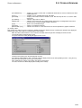
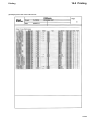
Title
Manual No.
Contents
User's Manual Commands
MICREX-SX series SPH
FEH200
Explains the system configuration, the memory and the
language of SPH.
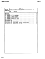
User's Manual Hardware,
MICREX-SX series SPH
FEH201
Explains the system configuration, the specifications and
operations of modules in the MICREX-SX series.
User's Manual P/PE-link modules, MICREXSX series SPH
FEH203
Explains the communication specifications of P/PE-link, the
specifications and operations of the modules.
User's Manual T-link master module / T-link
interface module, MICREX-SX series SPH
FEH204
Explains the communication specifications of the T-link, the
specifications and operations of the T-link master module /
the T-link interface module.
User's Manual D300win Ver1.x
<GUIDE>, MICREX-SX series
FEH250
Explains the basic operations of D300win Ver1.x, the
programming and monitoring for MICREX-SX series.
User's Manual D300win Ver1.x
<REFERENCE>, MICREX-SX series
FEH251
Explains the menu and icon of D300win and all of the
operations of D300win Ver1.x.
Notes
1. This manual may not be reproduced in whole or part in any form without prior written approval by the manufacturer.
2. The contents of this manual (including specifications) are subject to change without prior notice.
3. If you find any ambiguous or incorrect descriptions in this manual, please write them down (along with the manual No.
shown on the cover) and contact FUJI.
*Microsoft, Windows are trademarks of Microsoft Corporation in the USA and other countries.
*Intel486 and Pentium are trademarks or registered trademarks of Intel Corp.
Safety Precautions
Before mounting, wiring, operation, maintenance and inspection of the device, be sure to read the operating instructions
carefully to ensure proper operation. The operation instructions should be furnished to the maintenance supervisions of final
users.
Warning : Incorrect handling of the device may result in death or serious injury.
Caution
: Incorrect handling of the device may result in minor injury or physical damage.
Even some items indicated by “Caution” may also result in a serious accident.
Both safety instruction categories provide important information. Be sure to strictly observe these instructions.
Caution
◊ Do not bring the magnetic object close to the floppy disk, otherwise, failure might be caused.
◊ Insert the memory cassette, floppy disk and engage the loader connector in a correct orientation, otherwise, failure or
erratic operation might be caused.
◊ Sufficiently make sure of safety before program change, forced output, starting, stopping or anything else during a run.
The wrong operation might break or cause machine problems.
◊ Do not turn off the loader during a run (accessing to the hard disk or the floppy disk, communicating to the PLC), otherwise,
missing of data, failure or erratic operation of products, damage or trouble of machines might be caused.
◊ Use this package in the operating environment of software described in the user's manual, otherwise, failure or erratic
operation might be caused.
◊ Perform the version-up operation by the explanation of the user's manual, otherwise, failure or erratic operation might be
caused.
◊ Engage the communication cable connector firmly and lock it, otherwise, erratic operation be might caused.
◊ Do not touch the disk's surface of the floppy disk, otherwise, failure or erratic operation might be caused.
◊ Perform the periodic inspection for the floppy disk drive and the hard disk drive. If the data are made by the fault disk,
failure or erratic operation of the system might be caused.
◊ When disengaging the communication cable or the power cable, do not pull the cord, otherwise, failure, erratic operation
or damage might be caused.
Revision
*Manual No. is shown on the cover.
Printed on
*Manual No.
August. 2000 FH254
Revision contents
First edition (Products Version 2.1.xxx)
Contents
Preface
Safety Precautions
Revision
Contents
Points for Using This Manual
Page
Precautions for Upgrading
1. Handling Projects Created with Old Versions of D300win ............................................................................. 1
2. To Prevent Verification Error of Projects .......................................................................................................... 1
3. Procedure for Upgrading from Old Version to New Version System ............................................................ 2
4. Converting Projects Created with Old Version System .................................................................................. 6
5. Notes on upgrading from D300win Version 1 to Version 2 ............................................................................. 8
Section 1 Preparation and Starting the D300win System ............................. 1-1
1-1 D300win System Configuration ............................................................................................................1-1
1-1-1 D300win system configuration ...................................................................................................................... 1-1
1-2 System Requirements ............................................................................................................................1-2
1-2-1 Hardware ....................................................................................................................................................... 1-2
1-2-2 Software ......................................................................................................................................................... 1-2
1-3 Installation Procedure ............................................................................................................................1-3
1-3-1 About D300win software package ................................................................................................................. 1-3
1-3-2 Installation ..................................................................................................................................................... 1-3
1-3-3 D300win program group ................................................................................................................................ 1-7
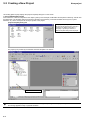
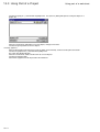
1-4 Changing Program Configuration .........................................................................................................1-8
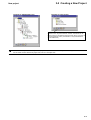
1-5 Starting The Uninstall Program .............................................................................................................. 1-9
1-6 Starting D300win ..................................................................................................................................1-11
1-6-1 How to start D300win .................................................................................................................................. 1-11
1-6-2 D300win starting screen ............................................................................................................................. 1-13
Section 2 D300win Common Items ................................................................... 2-1
2-1 Screen Structure and Functions of D300win ...................................................................................... 2-1
2-1-1 User interface ............................................................................................................................................... 2-1
2-1-2 Window layout ............................................................................................................................................... 2-2
2-1-3 Menu bar ....................................................................................................................................................... 2-3
2-1-4 Tool bar .......................................................................................................................................................... 2-3
2-1-5 Keyboard shortcut ......................................................................................................................................... 2-4
2-1-6 Shortcut menu ............................................................................................................................................... 2-7
2-1-7 Easy operation menu ................................................................................................................................... 2-8
2-1-8 Status bar .................................................................................................................................................... 2-10
2-1-9 D300win help function ................................................................................................................................. 2-10
2-2 D300win Windows ................................................................................................................................2-12
2-2-1 Outline of the project tree window ............................................................................................................. 2-12
2-2-2 Display method of the project tree window ................................................................................................ 2-12
2-2-3 Graphic editor and operation ....................................................................................................................... 2-14
2-2-4 Overview window ......................................................................................................................................... 2-22
2-2-5 Text editor .................................................................................................................................................... 2-23
Contents
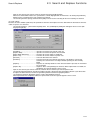
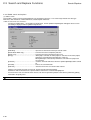
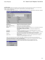
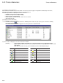
2-3 Search and Replace Functions ........................................................................................................... 2-26
2-3-1 Local search and replace ............................................................................................................................ 2-26
2-3-2 Global search and replace .......................................................................................................................... 2-28
2-4 Cross-references ..................................................................................................................................2-30
2-5 Saving and Exiting Project/Worksheet ............................................................................................... 2-32
2-5-1 Saving and exiting a worksheet ................................................................................................................. 2-32
2-5-2 Saving and exiting a project ........................................................................................................................ 2-34
2-6 Exiting D300win .................................................................................................................................... 2-36
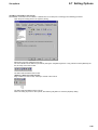
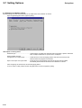
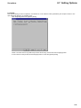
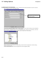
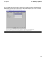
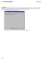
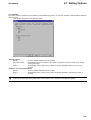
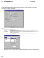
2-7 Setting Options ..................................................................................................................................... 2-37
2-7-1 Setting the tool bars and commands .......................................................................................................... 2-38
2-7-2 Settings for D300win startup ....................................................................................................................... 2-40
2-7-3 Build ............................................................................................................................................................. 2-41
2-7-4 Setting the file save destination .................................................................................................................. 2-42
2-7-5 Setting page layout ...................................................................................................................................... 2-43
2-7-6 Debug .......................................................................................................................................................... 2-44
2-7-7 Backup ......................................................................................................................................................... 2-45
2-7-8 Setting the text editor .................................................................................................................................. 2-46
2-7-9 Setting text colors ........................................................................................................................................ 2-47
2-7-10 Setting the graphic editor .......................................................................................................................... 2-48
2-7-11 Graphic editor colors ................................................................................................................................. 2-50
Section 3 Preparation for Creating a Project ................................................... 3-1
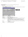
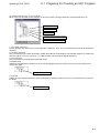
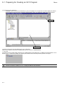
3-1 Developing a Project with D300win ...................................................................................................... 3-1
3-1-1 Project development flow .............................................................................................................................. 3-1
3-1-2 Documentation flow ....................................................................................................................................... 3-2
3-2 Creating a New Project ..........................................................................................................................3-3
3-2-1 Starting D300win ........................................................................................................................................... 3-3
3-2-2 Relationship between PC system and D300win ........................................................................................... 3-9
3-2-3 Project tree .................................................................................................................................................. 3-10
3-3 Creating Program Organization Units (POUs) .................................................................................. 3-13
3-3-1 How to insert a POU and worksheet ........................................................................................................... 3-14
3-3-2 Changing the properties of POU and worksheets ...................................................................................... 3-18
3-3-3 Deleting POU and worksheet ...................................................................................................................... 3-19
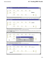
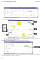
Section 4 Editing in LD/FBD Language ............................................................ 4-1
4-1 Preparation for Creating LD/FBD Code................................................................................................ 4-1
4-1-1 Introduction to LD/FBD language .................................................................................................................. 4-1
4-1-2 Precautions for programming in LD/FBD language ...................................................................................... 4-3
4-1-3 Inserting POUs .............................................................................................................................................. 4-4
4-2 Creating an LD Circuit ...........................................................................................................................4-9
4-2-1 Inserting an LD circuit ................................................................................................................................... 4-9
4-2-2 Inserting contacts/coils ................................................................................................................................ 4-12
4-2-3 Adding a new circuit .................................................................................................................................... 4-16
4-2-5 Changing the properties of contacts and coils ........................................................................................... 4-19
4-2-6 Circuit comments ......................................................................................................................................... 4-21
4-3 Creating FBD Circuits ..........................................................................................................................4-25
4-3-1 Inserting functions or function blocks .......................................................................................................... 4-22
4-3-2 Connecting objects to the FCT/FB terminals .............................................................................................. 4-25
4-3-3 Replacing a function or function block ........................................................................................................ 4-31
4-3-4 Increasing or reducing the number of input terminals ................................................................................ 4-34
4-3-5 Changing input/output terminals to negated terminals ............................................................................... 4-37
Contents
4-3-6 Changing the frame height of a block ......................................................................................................... 4-38
4-3-7 Setting flag type ........................................................................................................................................... 4-39
4-3-8 Displaying the execution order of the FBD circuit ....................................................................................... 4-41
4-3-9 Feedback display of FBD circuit .................................................................................................................. 4-42
4-3-10 Inserting connectors, jumps or labels ....................................................................................................... 4-42
4-3-11 Precautions for describing FBD and LD circuits together ........................................................................ 4-45
Section 5 Editing in SFC Language .................................................................. 5-1
5-1 Preparing for Creating an SFC Program ..............................................................................................5-1
5-1-1 Introduction to SFC ...................................................................................................................................... 5-1
5-1-2 Inserting POUs .............................................................................................................................................. 5-2
5-2 Creating SFC Program ...........................................................................................................................5-7
5-2-1 Inserting SFC program .................................................................................................................................. 5-7
5-2-2 Inserting a branch ......................................................................................................................................... 5-8
5-2-3 How to increase the number of branches ................................................................................................... 5-11
5-3 Setting/Changing Step Elements ........................................................................................................ 5-12
5-3-1 Changing step elements ............................................................................................................................. 5-12
5-4 Setting/Changing Actions ................................................................................................................... 5-22
5-4-1 Changing the name of action block ............................................................................................................. 5-22
5-4-2 Adding and inserting action blocks ............................................................................................................. 5-23
5-4-3 Connecting variables to an action ............................................................................................................... 5-25
5-4-4 Creating action programs ........................................................................................................................... 5-28
5-5 Connecting a Variable/Program to a Transition ................................................................................. 5-31
5-5-1 Connecting a variable to a transition ........................................................................................................... 5-31
5-5-2 Connecting an FBD (LD) object to a transition ........................................................................................... 5-33
5-5-3 Creating a transition program ...................................................................................................................... 5-36
Section 6 Editing in IL Language ...................................................................... 6-1
6-1 Preparing for Creating IL Code ............................................................................................................. 6-1
6-1-1 Introduction to IL language ........................................................................................................................... 6-1
6-1-2 Inserting a POU ............................................................................................................................................. 6-2
6-1-3 How to program IL code ................................................................................................................................ 6-4
6-2 How to Use Functios/Function Blocks ................................................................................................. 6-7
6-2-1 How to use functions ..................................................................................................................................... 6-7
6-2-2 How to use function blocks ............................................................................................................................ 6-9
6-3 Sample Use of Jump/Label
Section 7 POU Editing in ST Language ............................................................ 7-1
7-1 Preparation for Creating ST Code ........................................................................................................ 7-1
7-1-1 Introduction to ST language .......................................................................................................................... 7-1
7-1-2 ST language commands and assignment statements .................................................................................. 7-1
7-1-3 Inserting POUs .............................................................................................................................................. 7-2
7-1-4 Writing ST code ............................................................................................................................................. 7-4
7-2 How to Use Functions/Function Blocks ..............................................................................................7-7
7-2-1 How to use functions ..................................................................................................................................... 7-7
7-2-2 How to use function blocks (FB) ................................................................................................................... 7-9
Section 8 Definition of Variables Declaration/Derived Data ............................ 8-1
8-1 Variables Declaration .............................................................................................................................8-1
8-1-1 Outline of variables ........................................................................................................................................ 8-1
8-1-2 How to declare variables with D300win ........................................................................................................ 8-2
Contents
8-1-3 Variables declaration while editing codes ..................................................................................................... 8-3
8-1-4 Variables declaration by the variables editor ................................................................................................ 8-9
8-2 Content of Variable Declaration .......................................................................................................... 8-14
8-2-1 Specification of variable .............................................................................................................................. 8-15
8-2-2 Specification of block ................................................................................................................................... 8-20
8-2-3 Selecting the scope of variables and the worksheet .................................................................................. 8-21
8-3 Importing/Exporting Variables to/from a File .................................................................................... 8-24
8-3-1 File format of variable definition data .......................................................................................................... 8-24
8-3-2 Import from a file ......................................................................................................................................... 8-27
8-3-3 Exporting to a file ........................................................................................................................................ 8-29
8-4 Declaration of Derived Data ................................................................................................................ 8-31
8-4-1 Derived data types ...................................................................................................................................... 8-31
8-4-2 How to declare derived data types .............................................................................................................. 8-31
8-4-3 Sample declaration of the derived data type .............................................................................................. 8-35
Section 9 User-Defined FCT/FB ........................................................................ 9-1
9-1 User-Defined Functions ......................................................................................................................... 9-1
9-1-1 ........................................................................................................................................................................ 9-1
9-1-2 ........................................................................................................................................................................ 9-1
9-2 User-Defined Function Block ................................................................................................................9-3
9-2-1 Creating a POU for function .......................................................................................................................... 9-3
9-2-2 Creating a user-defined function ................................................................................................................... 9-5
9-2-3 Creating User-Defind Function Block ............................................................................................................ 9-8
9-2-4 How to create and display help ................................................................................................................... 9-11
9-2-5 Compiling a POU and saving a project ....................................................................................................... 9-14
9-3 Using User-Defined FCT/FB ................................................................................................................ 9-15
9-3-1 Using the library function ............................................................................................................................ 9-15
9-3-2 Calling a user-defined FCT/FB ................................................................................................................... 9-16
Section 10 Using an Existing Project ............................................................. 10-1
10-1 Copying a Project ............................................................................................................................... 10-1
10-1-1 Making a copy of a project ........................................................................................................................ 10-1
10-2 Using the Library Functions ............................................................................................................. 10-2
10-2-1 Library registration .................................................................................................................................... 10-2
10-2-2 Using a library ........................................................................................................................................... 10-5
10-2-3 Changing the path to a library file ............................................................................................................. 10-7
10-2-4 Deleting a registered library ...................................................................................................................... 10-7
10-3 Using Part of a Project ....................................................................................................................... 10-8
10-3-1 Opening a project other than that being edited ........................................................................................ 10-8
10-3-2 Using POUs ............................................................................................................................................... 10-9
Section 11 PC Structure/Operation Definition ............................................... 11-1
11-1 PC Structure Definition Overview .................................................................................................... 11-1
11-1-1 Physical hardware folder overview ............................................................................................................ 11-1
11-1-2 Editing the structure of the [Physical Hardware] subtree ......................................................................... 11-2
11-2 Setting Resources .............................................................................................................................. 11-4
11-2-1 Communication settings ............................................................................................................................ 11-4
11-2-2 CPU running definition .............................................................................................................................. 11-6
11-2-3 Defining the CPU memory size ................................................................................................................. 11-7
11-2-4 Setting for the compiler ........................................................................................................................... 11-10
Contents
11-3 Registering Tasks and Programs ....................................................................................................11-13
11-3-1 Types and operations of tasks ................................................................................................................. 11-13
11-3-2 Inserting and setting tasks ...................................................................................................................... 11-14
11-3-3 Program registration ................................................................................................................................ 11-16
11-4 System Definition .............................................................................................................................11-17
11-4-1 Using the system structure definition window ......................................................................................... 11-17
11-4-2 Setup items in the system structure definition window ........................................................................... 11-19
11-4-3 Inserting/changing a module ................................................................................................................... 11-20
11-4-4 Setting parameters for a CPU module .................................................................................................... 11-24
11-4-5 Input/output parameters .......................................................................................................................... 11-32
11-4-6 System structure definition for multi-CPU system .................................................................................. 11-35
11-5 System properties ............................................................................................................................11-37
11-5-1 System running definition ........................................................................................................................ 11-37
11-5-2 Outline of redundant CPU system .......................................................................................................... 11-39
11-5-3 Fail-soft operation setting ........................................................................................................................ 11-47
Section 12 Compiling/Loading ........................................................................ 12-1
12-1 Compiling Projects .............................................................................................................................12-1
12-1-1 Before compiling projects .......................................................................................................................... 12-1
12-1-2 D300win compilation functions ................................................................................................................. 12-2
12-1-3 Running compilation .................................................................................................................................. 12-5
12-2 Preparation for Loading ...................................................................................................................12-11
12-2-1 Outline of loading .................................................................................................................................... 12-11
12-2-2 Checking the connection between D300win and the PC ........................................................................ 12-12
12-3 Downloading .....................................................................................................................................12-15
12-3-1 Downloading ............................................................................................................................................ 12-15
12-4 Uploading (under development) .....................................................................................................12-21
12-4-1 Upload execution ..................................................................................................................................... 12-21
12-4-2 Language conversion function ................................................................................................................ 12-25
12-5 Verification ........................................................................................................................................12-26
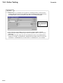
Section 13 Online Test Functions ................................................................... 13-1
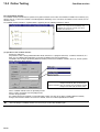
13-1 Online Test Function Overview ......................................................................................................... 13-1
13-1-1 Individual CPU test functions .................................................................................................................... 13-1
13-1-2 Configuration batch control function ......................................................................................................... 13-2
13-2 Running and Monitoring the CPU module .......................................................................................13-3
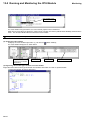
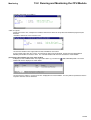
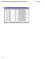
13-2-1 Running the CPU module ......................................................................................................................... 13-3
13-2-2 Resource information ................................................................................................................................ 13-7
13-2-3 Program/variable monitor basic operations .............................................................................................. 13-8
13-2-4 Using a watch window ............................................................................................................................. 13-13
13-3 Online Testing ...................................................................................................................................13-17
13-3-1 Forced ON/OFF and overwrite ................................................................................................................ 13-17
13-3-2 Break point function ................................................................................................................................ 13-23
13-3-3 Step-by-step execution ........................................................................................................................... 13-28
13-3-4 Condition monitor .................................................................................................................................... 13-30
13-3-5 Logic Analyzer (under development) ...................................................................................................... 13-31
13-3-6 Program control ....................................................................................................................................... 13-34
13-4 Calendar Function ............................................................................................................................13-35
13-4-1 Range of calendar ................................................................................................................................... 13-35
13-4-2 Accuracy of the calendar function ........................................................................................................... 13-35
13-4-3 How to set the monitor from D300win ..................................................................................................... 13-35
Contents
13-5 SX Control Utility ..............................................................................................................................13-36
13-5-1 Outline of SX control utility ...................................................................................................................... 13-36
13-5-2 Starting SX control utility ......................................................................................................................... 13-36
13-5-3 The {SX Control Utility} window .............................................................................................................. 13-40
13-5-4 Operation of the SX control utility (Memory check) ................................................................................ 13-43
13-5-5 Backup of PC memory ............................................................................................................................ 13-49
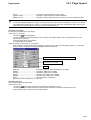
Section 14 Page Layout and Printing ............................................................. 14-1
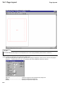
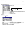
14-1 Page Layout ........................................................................................................................................14-1
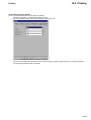
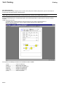
14-1-1 Page layout editor ..................................................................................................................................... 14-1
14-1-2 Editing a page layout ................................................................................................................................. 14-2
14-1-3 Starting page layout .................................................................................................................................. 14-4
14-1-4 Saving a page layout ............................................................................................................................... 14-12
14-1-5 Page layouts prepared for D300win ....................................................................................................... 14-12
14-2 Printing ..............................................................................................................................................14-14
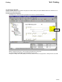
14-2-1 Printing overview ..................................................................................................................................... 14-14
14-2-2 Confirmation and modification of printer settings ................................................................................... 14-14
14-2-3 Assigning page layouts ........................................................................................................................... 14-15
14-2-4 Print preview ............................................................................................................................................ 14-16
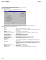
14-2-5 Printing individual .................................................................................................................................... 14-17
14-2-6 Printing an entire project/project part ...................................................................................................... 14-18
14-2-7 Sample prints .......................................................................................................................................... 14-19
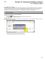
Section 15 Saving and Calling a Project ........................................................ 15-1
15-1 Saving a Project .................................................................................................................................15-1
15-1-1 Project save overview ............................................................................................................................... 15-1
15-1-2 Saving the edited version of a worksheet ................................................................................................. 15-1
15-1-3 Saving projects .......................................................................................................................................... 15-2
15-2 Zipping and Unzipping Project Files ................................................................................................ 15-3
15-2-1 Zipping project files ................................................................................................................................... 15-3
15-2-2 Unzipping project files ............................................................................................................................... 15-5
15-3 Dividing and Merging a Zipped Project File .................................................................................... 15-6
15-3-1 Dividing a zipped project file ..................................................................................................................... 15-6
15-3-2 Merging files ............................................................................................................................................ 15-10
15-4 Deleting Projects ..............................................................................................................................15-12
Section 16 Auxiliary Functions ....................................................................... 16-1
16-1 Password Function ............................................................................................................................16-1
16-1-1 Validity of password ................................................................................................................................... 16-1
16-1-2 Registration of a new password ................................................................................................................ 16-1
16-1-3 Changing the password ............................................................................................................................ 16-3
16-1-4 Canceling the password ............................................................................................................................ 16-4
16-1-5 Temporarily canceling a password ............................................................................................................ 16-5
16-2 Failure Diagnosis ...............................................................................................................................16-6
16-2-1 Using the failure diagnostic function ......................................................................................................... 16-6
16-2-2 Saving and displaying RAS information .................................................................................................... 16-8
16-3 Loader Network ................................................................................................................................16-10
16-3-1 Outline of loader network ........................................................................................................................ 16-10
16-3-2 Setting a network ..................................................................................................................................... 16-11
Contents
16-4 Function to Save Projects In a Memory Card ................................................................................ 16-16
16-4-1 Outline of the function ............................................................................................................................. 16-16
16-4-2 How to handle/operate the memory card ................................................................................................ 16-16
16-4-3 Writing programs/system definitions to the memory card ...................................................................... 16-20
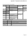
Appendix 1 Expansion Function Block (FB) ................................................ A 1-1
Appendix 1-1 Expansion Function Block List ........................................................................................ A1-1
Appendix 1-2 Install/Uninstall of Expansion Function Blocks ............................................................. A1-2
Points for Using This Manual
What Is D300win?
(1) D300win is program-creation system software for programmable controllers (hereinafter called PCs) which operates on
Microsoft Windows and conforms to international standard IEC 61131-3.
Based on standard Microsoft Windows, D300win provides an easy operating environment for your developed programcreation system software.
(2)
D300win supports 4 languages (IL, ST, LD, FBD) which follow the IEC 61131-3 standard, and one element (SFC),
allowing you to select languages which best match the processing capacity of your PC system. In addition, two
language editors (graphic editor and text editor) are provided for each of these languages.
(3)
In D300win the PC programs, including the hardware configuration, are dealt with by the Project method. Projects are
expressed in an easy-to-understand tree structure with items such as the program organization unit (POU), which is an
element used to construct a PC system, libraries, user-defined data types, and system hardware configuration.
(4)
D300win provides programming expressions which are clear and easy to understand, such as programming by
variables and description comments which can be set freely in programs. D300win also provides excellent
documentation functions, allowing the user to freely define the printing format.
How to Use This Manual
This document describes the functions of D300win, how to use them, and all operations with the MICREX-SX Series
programmable controller, from programming to on-line testing. For those who want to understand IEC 61131-3, “User’s Manual
D300win <Introduction>” is available which, as a guide to IEC 61131-3, explains what IEC 61131-3 languages are in
comparison with languages used in conventional Fuji PCs. It also provides an outline of the functions and basic operating
method of D300win.
Concerning the Descriptions in This Manual
This manual is written using the following conventions:
•
◊
[]
<ALT>
<ALT> + <F4>
{}
Used for list.
Used for actual operation.
Used to denote icons, menu item names or object names. For example, [File] menu or [OK] button in a
dialog box.
<> is used to denote the name of a key on the keyboard which is used for input.
“+” is used to mean that two keys are pressed simultaneously.
Used to denote dialog names.
Used for important information and key points.
Indicates another manual or a page of this manual for reference
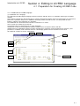
Precautions for Upgrading
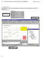
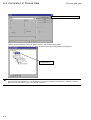
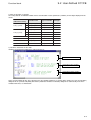
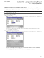
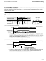
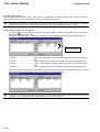
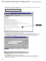
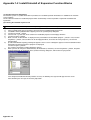
1. Handling Projects Created with Old Versions of D300win
The following procedure applies to the D300win user upgrading an old version of D300win system (Version 1.x) to a new
version (Version 2.x). Since the functions are greatly changed in the new version, carefully read this manual to correctly use
the system.
New D300win users can skip this section and proceed to Section 1.
Before upgrading your D300win system, it is recommended to zip source programs (projects) with the old version
system and store them as zipped project files. For how to zip projects, see “15-2-1 Zip of project files.”
For the new version of D300win, part of the internal codes (machine codes) for programs transferred to PC are changed.
Therefore, even with the same source programs (projects), there is a difference in the result of compilation (internal codes)
between new and old versions.
As a result, if a program that is downloaded into a PC using an old version system is verified on-line with the corresponding
program that was compiled by the new version system, a verification error will occur.
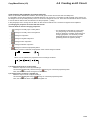
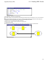
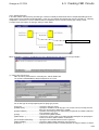
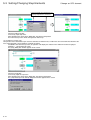
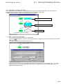
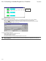
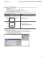
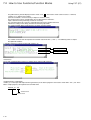
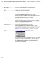
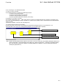
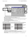
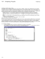
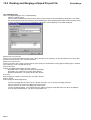
Transfer
Verification
Power
supply
CPU
Old version D300win system
Program (project)
created by an old version
system
Verification
(see note)
New version D300win system
Note:
When a zipped program (project) is
unzipped and be verified as it, is it will
match; when unzipped program is verified
after compilation, a mismatch will result.
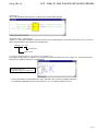
2. To Prevent Verification Error of Projects
Use the new version system to unzipped projects which were zipped by an old version system and then verify them on-line, as
they are (without compilation), with the projects downloaded into a PC which uses the old version system.
1
Precautions for Upgrading
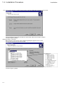
3. Procedure for Upgrading from Old Version to New Version System
Use the following procedure to upgrade the D300win system:
Step 1) Uninstall the D300win Version 1 system.
Step 2) Uninstall the standard expansion function block (FB) for the D300win Version 1 system.
Step 3) Install the D300win Version 2 system.
Step 4) Make backup copies of projects (files) created with the D300win Version 1 system.
Step 5) Install the standard expansion FB for the D300win Version 2 system.
Step 6) Convert the projects (files) created with the D300win Version 1 system to those for the Version 2 system.
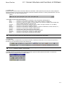
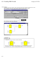
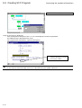
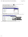
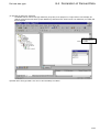
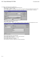
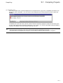
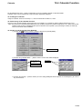
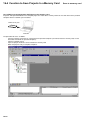
(1) Uninstalling the D300win Version 1 system
Before installing the new version system, be sure to uninstall the old version system. The new
version system may not successfully install with the old system retained.
Delete files related to the D300win Version 1 system from the hard disk using the following procedure:
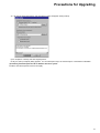
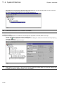
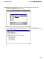
1) Left-click the Windows 98/95 [Start] menu, select the [D300win] program folder from the [Programs] submenu, and then
left-click the [D300win Uninstall] command.
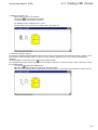
The {Confirm File Deletion} message box appears.
To execute deletion, left-click the [Yes] button.
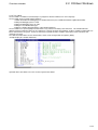
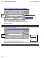
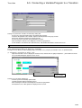
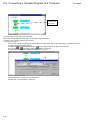
2) Deletion is executed.
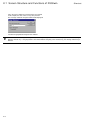
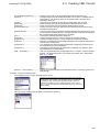
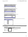
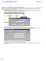
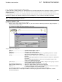
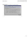
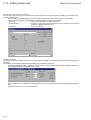
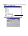
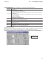
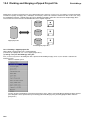
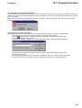
Upon completion of the deletion, the window shown below appears with the removed items checked.
3) Left-click the [OK] button to close the {Remove Programs From Your Computer} dialog.
2
Precautions for Upgrading
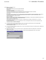
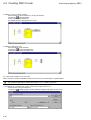
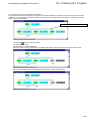
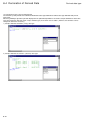
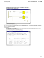
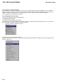
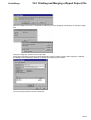
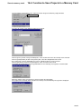
(2) Uninstalling the old version of expansion FB
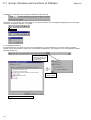
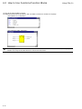
Delete the old version of expansion FB files from the hard disk using the following procedure:
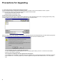
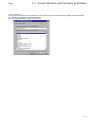
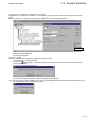
1) Left-click the Windows 95/98 [Start] menu, and select [Control panel] from the [Settings] submenu to display the {Control
Panel} dialog.
Left-double-click the [Add/Remove Programs] icon.
Select [STANDARD EXPANSION FB] from the list in the {Install/Uninstall} panel of the {Add/Remove Programs
Properties} dialog, and then left-click the [Add/Remove ...] button.
To execute deletion, left-click the [Yes] button.
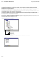
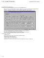
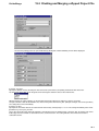
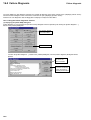
2) Deletion is executed.
Upon completion of the deletion, the window shown below appears with the removed items checked.
3) Left-click the [OK] button to close the {Remove Programs From Your Computer} dialog.
3
Precautions for Upgrading
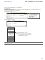
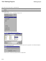
(3) Installing the D300win Version 2 system
Install the D300win Version 2 system. For how to install the new system, see “1-3 Installation Procedure.”
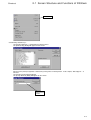
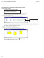
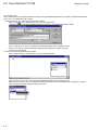
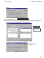
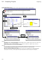
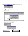
(4) Making backup copies of old projects (files)
Backup the projects (files) created with the old version system.
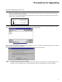
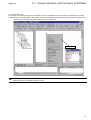
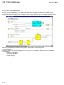
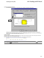
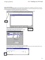
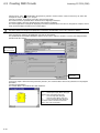
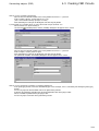
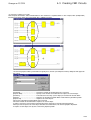
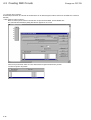
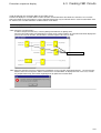
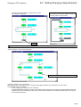
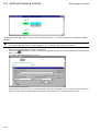
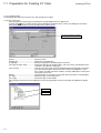
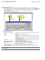
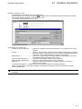
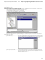
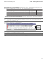
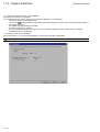
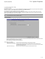
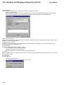
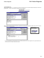
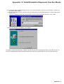
1) While installation of the D300win Version 2 system is in progress, the {Question} dialog shown below is displayed.
Left-click the [Yes] button, and the {Backup utility} dialog appears to set items necessary for backup of the project files
created with the old version system. After the new D300win system is installed, the {Backup utility} dialog can also be
displayed by selecting the Windows 95/98 [Start] menu, [Programs] submenu, [D300win] folder, and then [Backup utility],
or alternatively left-clicking the [Backup utility] command in the [Extras] menu.
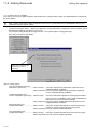
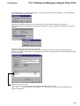
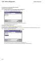
2) Set the backup information.
Specify the project folder for the old version system under the [Specification of backup source] item.
If you select [Automatic search], old project files in all hard disks are automatically searched.
Specify the backup destination folder under the [Specification of backup destination] item.
Specify a file format for saving the backup files under the [Preservation format of project] item. If you select [Zipped
project format], the project files are zipped and saved. In this case, the backup disk space is reduced, but the unzip
operation is necessary to open the files.
4
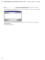
Precautions for Upgrading
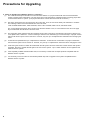
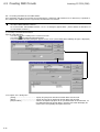
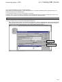
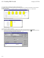
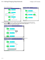
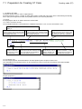
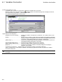
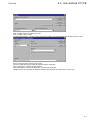
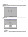
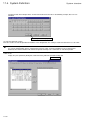
3) Left-click the [Execution] button, and the following dialog will appear starting backup.
Upon completion of backup, left-click the [Exit] button.
Finally, the {Setup Complete} dialog appears. For the subsequent steps, see the description of the D300win installation.
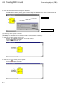
(5) Installing standard expansion FB for D300win Version 2 system
Install the standard expansion function block (FB).
5
Precautions for Upgrading
4. Converting Projects Created with Old Version System
Convert the projects (files) created with the D300win Version 1 system to those for the D300win Version 2 system.
There are two types of files created with the old version system as shown below.
• Normal project file (with an extension .pwt)
• Zipped file (with an extension .zwt)
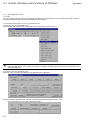
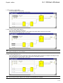
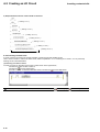
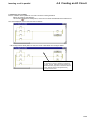
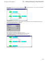
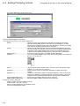
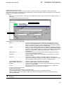
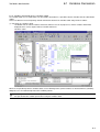
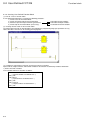
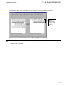
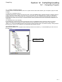
(1) Converting normal project files (*.pwt)
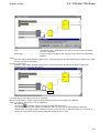
Left-click the [Open/Unzip project] command in the [File] menu to open the dialog shown below. Specify [Project Files (16-bit)
(*.pwt)] for [Files of type]. Select the target file, and then left-click the [Open] button.
When the dialog shown below appears, confirm that the selected project file is already backed up, and left-click the [Yes] button.
The selected project file of the old version is converted to the new version file of the D300win system.
<If a user library has been registered in the project>
If a user-created project has been registered in the converted project’s library, be sure to convert the user-created
project to a new version system file.
<If an expansion FB library has been registered in the project>
If an “expansion FB” supplied by Fuji Electric has been registered in the converted project’s library, delete the expansion
FB for D300win Ver. 1.x from the project tree, and then register the expansion FB for D300win Ver. 2.1x in the project
tree.
6
Precautions for Upgrading
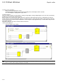
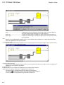
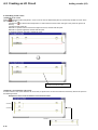
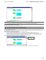
(2) Converting zipped project files (*.zwt)
Note: When another project exists as a library in a zipped project file created with the old version system, files may not be
correctly converted from the old version to the new version system if a file with the same name as the library exists in
the [Lib] folder under the [D300win] folder.
In this case, be sure to backup all project files created with the old version system, delete all files from the [Lib] folder,
and then carry out the unzip operation.
D300win
Lib
In computer
(System folder)
(Library folder)
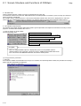
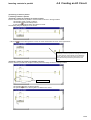
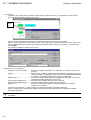
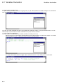
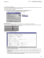
Left-click the [Open/Unzip project] command in the [File] menu to open the dialog shown below. Specify [Zipped Project Files
(*.zwt)] for [Files of type]. Select the target file, and then left-click the [Open] button.
Upon completion of unzipping, the following dialog will appear on the screen. Confirm that the selected project files are already
backed up, and then left-click the [Yes] button.
The selected project files of the old version are converted to those for the new version system.
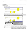
Note 1: After project conversion, be sure to recompile.
Note 2: If a project for each zipped file is included as a library, the project is also unzipped into the [LIBRARIES] folder. To
recompile, close the unzipped project, compile the libraries, reopen the unzipped project, and then recompile.
7
Precautions for Upgrading
5. Notes on upgrading from D300win Version 1 to Version 2
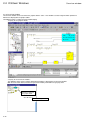
(1) The conventional ‘Project Information’ function has been deleted. If a project created with the old version D300win
system contains ‘project information,’ copy the project into a POU ‘description worksheet’ before converting project files
to the D300win Version 2 system. (The ‘project information’ content will be lost after file conversion.)
(2)
Part of the ‘Environment text’ in ‘Page layout’ cannot be used. Thus, the user must directly set characters or numbers.
The following 6 items of the ‘Environment Text’ cannot be used:
LAST CHANGE PAGE/TOTAL, PROJ AUTHOR, PROJ LAST CHANGE, PROJ TITLE, and TOTAL PAGE
The “Cross-referenced Program Print” function has also been deleted. Thus, a ‘cross-reference area’ set in the page
layout created with the old version cannot be used.
8
(3)
The respective names related to the SFC elements (action name, step name, and transition name) have a length of up
to 24 alphanumeric characters. A name consisting of more than 24 characters (up to 30 characters) in a project created
with the old version system can be used as is. However, only use up to 24 alphanumeric characters when changing the
name.
(4)
A task name is specified with up to 7 alphanumeric characters. A task name of 8 characters in a project created with
the old version system can be used as is. However, only use up to 7 alphanumeric characters when changing the name
(5)
A file storing the content of a watch list created with the old system cannot be read into the watch window after system
upgrading. Be sure to register the file again in the new version system. Up to 4 watch windows can be registered and
saved in the new system.
(6)
If the separately available extended FB is used, it is necessary to relink and recompile products compatible with the
D300win Version 2 system.
(7)
It is necessary for the SC matrix or POD loader (UG00S-3W) user to upgrade to the system compatible with the
D300win Version 2 system.
Section 1 Preparation and Starting the
D300win System
page
1-1 D300win System Configuration .............................................................................. 1-1
1-1-1 D300win system configuration ........................................................................................... 1-1
1-2 System Requirements ............................................................................................. 1-2
1-2-1 Hardware............................................................................................................................ 1-2
1-2-2 Software ............................................................................................................................. 1-2
1-3 Installation Procedure ............................................................................................. 1-3
1-3-1 About D300win software package...................................................................................... 1-3
1-3-2 Installation .......................................................................................................................... 1-3
1-3-3 D300win program group..................................................................................................... 1-7
1-4 Changing Program Configuration ........................................................................... 1-8
1-5 Starting The Uninstall Program ............................................................................... 1-9
1-6 Starting D300win .................................................................................................... 1-11
1-6-1 How to start D300win ....................................................................................................... 1-11
(1) Starting from the [Start] menu .......................................................................................................... 1-11
(2) Starting with the shortcut icon .......................................................................................................... 1-12
1-6-2 D300win starting screen .................................................................................................. 1-13
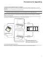
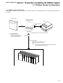
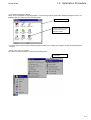
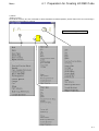
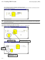
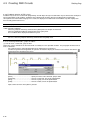
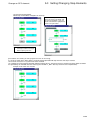
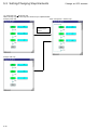
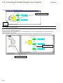
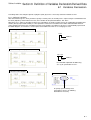
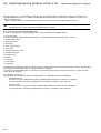
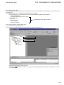
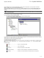
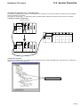
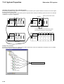
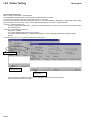
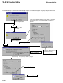
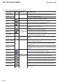
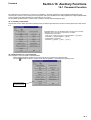
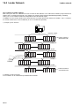
System configuration
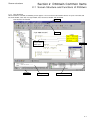
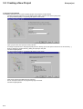
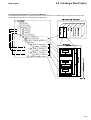
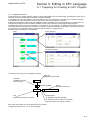
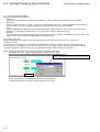
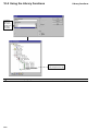
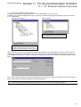
Section 1 Preparation and Starting the D300win System
1-1 D300win System Configuration
1-1-1 D300win system configuration
When D300win (system software) is installed in a personal computer, the computer system can be used as a programming tool
for Fuji PCs.
D300win system
Personal computer
(Windows95 or 98)
D300w
in syste
Printer
m
Printer connecting
cable
Install
RS-232C
Type : NP4H-SEDV2
-D300win system disk
-Standard expansion FB disk
-D300win <REFERENCE>
to RS-232C port of a personal computer
Converter
Coupling cable
NP4H-CNV (with a converter)
Note:
NP4H-CA2 (not with a converter)
Note:
When NP4H-CA2 is used,converter (Type:ME777A-FSP)
made by the BLACK BOX Co.,Ltd.
MICREX-SX
1-1
1-2 System Requirements
System configuration
1-2-1 Hardware
For D300win to operate normally, the following hardware requirements must be satisfied:
• IBM-compatible, DOS/V or PC98 series personal computer having Intel 486/33MHz or higher processor (Pentium/
133MHz or higher is recommended)
• Windows SVGA resolution of 800x600 or higher (SVGA resolution of 1024x768 are recommended.)
• 32 MB or more RAM
• 220 MB or more hard disk free space. However, the capacity of hard disk changes with the program to be installed.
(D300win system : 100MB or more, Standard expansion FB package : 120MB or more)
• 3.5-inch floppy disk drive (which can read 1.44 MB formatted floppy disks)
• Mouse
1-2-2 Software
For D300win to operate normally, the following software requirements must be satisfied:
• Microsoft Windows95/98
• Microsoft WindowsNT V.4.0
(Operation on Windows 3.1 or WindowsNT V.3.5 is not guaranteed.)
1-2
Installation
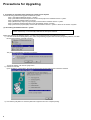
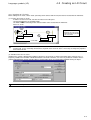
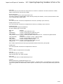
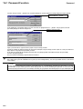
1-3 Installation Procedure
1-3-1 About D300win software package
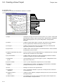
D300win software package is supplied in the form of multiple floppy disks. The installation disk includes the installation program
which automatically executes operations necessary for installation as well as the registration of icons.
Note: A project (file) created or zipped with the D300win system Japanese version cannot be used in an English version of the
system.
When installation is made via a PC network, depending on network or operating environment, copy or installations may
not be executed normally.
1-3-2 Installation
(1)
Disable any virus detection software and screen saver.
(2)
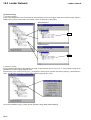
Select [Control panel] from the [Settings] submenu under the Windows95/98 [Start] menu.
(3)
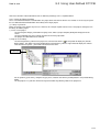
Left-double-click the [Add/Remove Programs] icon in the {Control panel} dialog box.
(4)
Left-click the [Install...] button.
(5)
Insert the No. 1 system disk, which contains the installation program, into the floppy disk drive.
(6)
Left-click the [Next >] button.
(7)
Make sure that “A:\SETUP.EXE” is displayed in the {Command line for installation program : } text box. If not, left-click
the [Browse...] button, select the drive No. for the floppy disk drive, and select file name [Setup.exe]. Left-click the
[Finish] button.
(8)
{Install Shield Wizard Preparing} working box appears on the screen. A dialog box appears in which installation related
information and how to operate this program are displayed.
Left-click the [Next >] button.
The {Choose Destination Location} dialog box appears.
(9)
When you want to change the default directory for installation (C:\D300win), left-click the [Browse...] button, designate
the desired directory for installation in the {Choose Directory} dialog box, and left-click the [Yes] button.
Note: Designate the directory name with
up to 8 alphanumeric characters.
1-3
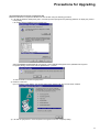
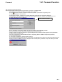
1-3 Installation Procedure
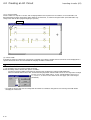
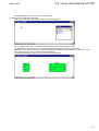
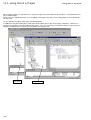
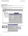
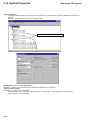
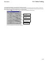
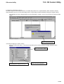
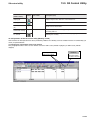
(10) Then left-click the [Next >] button, and the {Select setup type} dialog box will appear on the screen.
Select [Standard], [Compact] or [Custom] for setup method, and left-click the [Next >] button.
Left-click the [Next >] button.
<When [Custom] is selected>
When [Custom] is selected, the {Select component}] dialog box appears on the screen.
Check the box for the items you want to install.
Left-click the [Next >] button.
1-4
Installation
Installation
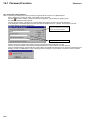
1-3 Installation Procedure
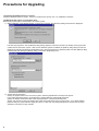
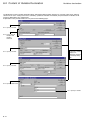
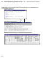
<Description of selectable items>
• D300win program
Basic D300win program. Must be selected and installed.
• MICREX-SX
Selected to create programs for the MICREX-SX series.
• SX simulator (sample)
Selected to simulate programs for the MICREX-SX Series on the personal computer (D300win).
This function is now under development and provided only as a sample.
• Page layout
Selected to use the sample page layout (5 types) which is necessary to print out a project or worksheet. (For details of
the sample page layout, refer to “14-1-5 Page layouts prepared for D300win.” File name “DEFAULT.plt” for the
introduced page layout is always installed.)
• POD link support
When a Fuji UG210/UG400 Series POD (programmable operating display) is connected to the MICREX-SX Series, this
function is used to relate assigned variables between them.
• Import & Export of variable name
This function is used to input a CSV file (text file) as a variable name or to output a variable name as a CSV file.
• Easy operation menu
The basic D300win operation can be selected from this menu (selecting what to do) to execute the operation steps
ranging from project creation to debugging.
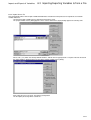
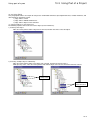
(11) The {Select program folder} dialog box appears on the screen. When you do not want to use the default folder
(D300win), input your desired program folder name in the text box.
Left-click the [Next >] button.
(12) The {Start file copying} dialog box appears on the screen. After checking the contents, left-click the [Next >] button, and
file copying will be started.
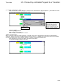
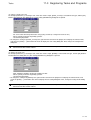
(13) When the installation of the first system disk ends, the {Setup Needs The Next Disk} dialog box as shown below
appears on the screen.
Insert the second disk, and left-click the [OK] button. Install the third and following disks in the same manner.
1-5
Installation
1-3 Installation Procedure
(14) When the installation of all disks is complete, the following {Question} dialog appears on the screen.
Left-click the [No] button in this dialog.
If you left-click the [Yes] button, the {Backup utility} dialog will appear on the screen enabling backup of project files
created with the D300win Version 1 system.
For the method or details of the {Backup utility} dialog, see “Precautions for Upgrading.”
(15) When the menu item [SX simulator] under [Custom] installation is selected, the following message appears after the
installation of all system disks is completed.
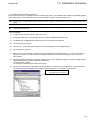
(16) When setup completes, the following screen appears.
When the menu item [Sample
project] under [Custom]
installation is selected, the
message “Immediately start
D300win using sample project” is
displayed here.
(17) After restarting the computer and confirming that there is no problem, check the optional [Yes, I want to restart my
computer now.] button, and then left-click the [Finish] button. Your computer is automatically restarted and the D300win
setup is complete.
1-6
Installation
1-3 Installation Procedure
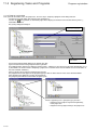
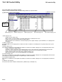
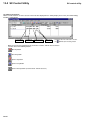
1-3-3 D300win program group
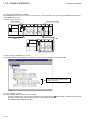
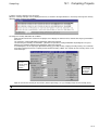
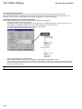
When setup is completed, the [D300win] folder is created in the [Program] folder under Windows95/98 [Start] menu. The
following icons are registered in the [D300win] folder.
D300win program folder
This icon appears when [SX
simulator (Sample)] has been
selected in the [Custom]
installation method.
* The items (icons) registered in the [D300win] program folder vary according to installation method (Standard/Compact/
Custom).
<[Start] menu after installation>
The content of program groups is registered in the [Start] menu.
To start D300win, left-click
this command.
1-7
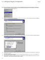
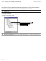
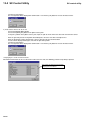
1-4 Changing Program Configuration
Install
It is possible to add or delete an optional program to or from the installed D300win system or to reinstall the set programs.
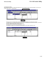
(1) Left-click the Windows [Start] menu button, select the [D300win] program group from the [Programs] menu, and then
left-click the [D300win Setup] program icon.
(2)
The {Preparing InstallShield Wizard} working box appears on the screen. Then, the dialog is displayed for modifying,
repairing, or removing program components.
(3)
Check the optional [Modify] button, and then left-click the [Next>] button. The {Select Components} dialog will appear
on the screen.
(4)
Check the box for an item to be added or uncheck the box for an item to be deleted in the component list, and then leftclick the [Next>] button.
If a program component has been added, the {Disk Change} dialog will appear on the screen. Insert the requested
disk, and left-click the [Next >] button.
Upon completion of program component installation, the {Maintenance Complete} dialog will appear on the screen as
shown below. Left-click the [Finish] button to close the dialog.
(5)
(6)
1-8
Uninstall
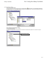
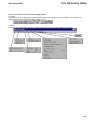
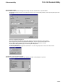
1-5 Starting The Uninstall Program
This operation deletes D300win system files from the hard disk and is executed according to the following procedure:
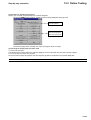
(1) Left-click the Windows [Start] menu button, select the [D300win] program group from the [Programs] menu, and then
left-click the [D300win Setup] program icon.
(2)
The {Preparing InstallShield Wizard} working box appears on the screen. Then, the dialog is displayed for modifying,
repairing, or removing program components.
(3)
Check the optional [Remove] button, and then left-click the [Next>] button. The {Confirm File Deletion} message box will
appear on the screen.
(4)
To execute deletion, left-click the [OK] button.
Deletion is executed.
The {Shared File Detected} dialog shown below may appear during uninstallation. In this case, if the [Yes] button is
selected, specific software may be disabled or, in worst case, Windows may be unable to run. Normally, left-click the
[No] button.
1-9
1-5 Starting The Uninstall Program
Uninstalling is completed.
(5)
Left-click the [OK] button, and the {Remove Program From Your Computer} dialog box will be closed.
Key-point:
The files created/stored by user cannot be deleted by the “uninstall program” operation.
1-10
Uninstall
Starting
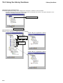
1-6 Starting D300win
1-6-1 How to start D300win
There are two methods, as explained below, for starting D300win. Do not start D300win by other method.
(1) Starting from the [Start] menu
When the installation of D300win system programs completes, a new program group which contains the following icons is
created. At the same time, the program group contents are registered in the [Start] menu.
To start D300win, left-click
this icon.
◊ Left-click the [Start] button, select the [D300win] program group from the [Programs] menu, and left-click the [D300win]
program icon.
The D300win system will be activated, displaying the image shown in 1-5-2 on the screen.
<Description of the icons for the program group>
The [D300win] icon is used to start the D300win system.
The [SX Control Utility] icon is used to activate the SX control utility of MICREX-SX series. With this utility, you can
monitor the input/output data to/from the basic input/output modules on the MICREX-SX system, or check the output.
The [File Divide & Merge] icon is used to activate the file divide/merge function. This function can divide a compressed
project file (larger than the capacity of a single floppy disk) into multiple files for storage, or merge divided files into to a
single file.
1-11
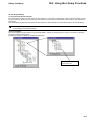
1-6 Starting D300win
Starting
The [Easy operation menu] icon is used to display a menu containing basic D300win operation items. An operation
ranging from project development to debugging can be selected and executed from the menu.
The [SX simulator] icon is used to activate the MICREX-SX simulator. The simulator can perform off-line simulation (on
the personal computer) of MICREX-SX Series programs created on D300win. (This function is installed when [Custom]
installation is selected.)
The [D300win help] icon is used to display the help (off-line mode help) screen for D300win. The contents of help topics
are displayed.
The text, which is opened by left-double-clicking the [D300win Help] icon, describes the precautions for using D300win
system. Please read this text before using D300win.
The [D300win uninstall] icon is used to activate the D300win uninstall program. The uninstall program deletes D300win
system-related files from the hard disk of the personal computer.
(2) Starting with the shortcut icon
It is possible to create a shortcut for [D300win] program icon and start D300win with the shortcut icon.
Do not create the shortcut icon by any method other than that explained below.
How to create the shortcut icon is explained below.
◊ Right-click Windows95 [Start] button.
Right-click
◊
◊
◊
◊
◊
Left-click the [Open] command, and the [Start menu] folder will be displayed.
Left-double-click the [Program] folder icon in the [Start menu] folder.
Left-double-click the [D300win] folder icon in the [Program] folder.
Left-click the [D300win start] icon, and left-click the [File] menu.
Left-click the [Create shortcut] command in the file menu.
Left-click
1-12
Starting
1-6 Starting D300win
The shortcut icon [D300win (2)] is created in the [D300win] program folder.
Shortcut icon for D300win
◊ Drag the [D300win (2)] shortcut icon onto the Windows desktop.
D300win can then be activated by left-double-clicking the shortcut icon on the desktop.
1-6-2 D300win starting screen
The following screen appears when D300win is activated.
The project (tree) which was last called, or nothing will be displayed on this screen.
1-13
Section 2 D300win Common Items
page
2-1 Screen Structure and Functions of D300win ........................................................ 2-1
2-1-1 User interface .................................................................................................................... 2-1
2-1-2 Window layout .................................................................................................................... 2-2
2-1-3 Menu bar ............................................................................................................................ 2-3
2-1-4 Tool bar .............................................................................................................................. 2-3
2-1-5 Keyboard shortcut .............................................................................................................. 2-4
2-1-6 Shortcut menu.................................................................................................................... 2-7
2-1-7 Easy operation menu ........................................................................................................ 2-8
(1) Outline ................................................................................................................................................ 2-8
(2) Activation and functions of the easy operation menu ......................................................................... 2-8
2-1-8 Status bar ......................................................................................................................... 2-10
2-1-9 D300win help function ...................................................................................................... 2-10
(1) How to display the Help window ....................................................................................................... 2-10
(2) Using [Contents] command ............................................................................................................... 2-10
2-2 D300win Windows .................................................................................................. 2-12
2-2-1 Outline of the project tree window ................................................................................... 2-12
2-2-2 Display method of the project tree window ..................................................................... 2-12
2-2-3 Graphic editor and operation............................................................................................ 2-14
(1) Selecting objects ............................................................................................................................... 2-14
(2) Moving objects .................................................................................................................................. 2-16
(3) Deleting objects ................................................................................................................................ 2-17
(4) Clearing worksheets ......................................................................................................................... 2-18
(5) Copying and pasting objects ............................................................................................................. 2-18
(6) Copying the content of a worksheet in a graphic file ........................................................................ 2-21
2-2-4 Overview window ............................................................................................................. 2-22
2-2-5 Text editor ......................................................................................................................... 2-23
(1) Selecting objects ............................................................................................................................... 2-24
(2) Copying and pasting objects ............................................................................................................. 2-24
2-3 Search and Replace Functions ............................................................................. 2-26
2-3-1 Local search and replace ................................................................................................. 2-26
(1) Local search ..................................................................................................................................... 2-26
(2) Local replace ..................................................................................................................................... 2-27
2-3-2 Global search and replace ............................................................................................... 2-28
(1) Global search .................................................................................................................................... 2-28
(2) Global replace ................................................................................................................................... 2-29
2-4 Cross-references ................................................................................................... 2-30
(1) Outline of cross-references ............................................................................................................... 2-30
(2) Display of cross-references ............................................................................................................... 2-30
(3) Setting a filter .................................................................................................................................... 2-31
2-5 Saving and Exiting Project/Worksheet ................................................................ 2-32
2-5-1 Saving and exiting a worksheet ...................................................................................... 2-32
(1) Saving a worksheet ........................................................................................................................... 2-32
(2) Exiting the worksheet ........................................................................................................................ 2-32
2-5-2 Saving and exiting a project ............................................................................................. 2-34
(1) Saving a project ................................................................................................................................ 2-34
(2) Exiting a project ................................................................................................................................ 2-35
2-6 Exiting D300win ..................................................................................................... 2-36
2-7 Setting Options ...................................................................................................... 2-37
2-7-1 Setting the tool bars and commands ............................................................................... 2-38
(1) Tool bar ............................................................................................................................................. 2-38
(2) Adding commands to the tool bar ..................................................................................................... 2-39
2-7-2 Settings for D300win startup ............................................................................................ 2-40
2-7-3 Build ................................................................................................................................. 2-41
2-7-4 Setting the file save destination ....................................................................................... 2-42
2-7-5 Setting page layout .......................................................................................................... 2-43
2-7-6 Debug ............................................................................................................................... 2-44
2-7-7 Backup ............................................................................................................................. 2-45
2-7-8 Setting the text editor ....................................................................................................... 2-46
2-7-9 Setting text colors ............................................................................................................. 2-47
2-7-10 Setting the graphic editor ............................................................................................... 2-48
2-7-11 Graphic editor colors ...................................................................................................... 2-50
Screen structure
Section 2 D300win Common Items
2-1 Screen Structure and Functions of D300win
2-1-1 User interface
When D300win is activated, the following screen appears. The user interface of D300win consists of 7 parts: menu bar, tool
bar, main window, status bar, message window, cross references window, and edit wizard.
Menu bar
User interface of D300win
Tool bar
Main window
• Project window
• Work space
Status bar
Message window
Edit wizard
Cross references window
2-1
2-1 Screen Structure and Functions of D300win
Window layout
2-1-2 Window layout
The windows displayed in D300win (including the project tree window, message window, and cross references window) are the
docking windows, each of which can be detached/attached. The window can be detached to optionally change its size or
display position.
<Sample changed layout>
Layout menu
The windows
corresponding to the
buttons in ON state are
displayed on the screen.
To detach the workspace,
left-click this button.
Left-double-click this border
to detach the window.
2-2
Menu/Tool bar
2-1 Screen Structure and Functions of D300win
2-1-3 Menu bar
[D300win] menu contains various commands. With these commands, various processing necessary for creating a project or
operating D300win can be executed. The commands contained in individual submenus are briefly explained below. The menu
and submenu items vary with the working status.
<Menu>
<Commands contained in each menu item>
• [File] .................. Contains the commands for configuring, saving, designing or printing projects.
• [Edit] ................. Contains the commands used for editing, such as object selection, cut and paste.
• [View] ................ Contains the project tree window, message window, cross references window, watch window, logic
analyzer window, Edit Wizard, and status bar.
• [Project] ............ Contains the commands for editing the project. (Library, Data type, and POU, etc. are added.)
• [Build] ............... Contains the commands for compiling a project.
• [Objects] ........... Contains the commands for editing the program. (Function/ Function block, Contact and Coil, etc. )
• [Layout] ............. Contains the commands for designing a display layout.
• [Online] ............. Contains online mode commands and various utilities.
• [Extras] ............. Contains the commands for setting basic D300win operations.
• [Window] ........... Contains the commands for changing the window display.
• [Help] ................ Contains the commands for activating the help function.
Commands contained in these menu items change according to the program section to be worked or the editor
selected. The places where each command can be used are explained in the Help window.
2-1-4 Tool bar
The tool bar contains multiple buttons. By using these buttons, frequently used functions can be executed easily. All these
functions can be executed from menu or with shortcut icon.
The items (buttons) contained in the tool bar can be optionally customized. For how to customize the tool bar items,
see “2-7-1 Setting the tool bars and commands.”
If the tool activated by the button is not recognized at a glance, place the mouse pointer on the button. The tool name
(command name) will appear below the mouse pointer.
2-3
2-1 Screen Structure and Functions of D300win
Shortcut
In addition, the explanation of the command is displayed on the status bar.
The tool bar is a free tool bar. The move handle at the edge of the tool bar can be dragged and dropped to the main window
(workspace) to display the tool bar as a window.
Move handle
2-1-5 Keyboard shortcut
A keyboard shortcut is a function to execute, from the keyboard, the same operation as by using the tool bar. Keyboard
shortcuts can be operated with a single key or a combination of multiple keys. For D300win, the user can optionally customize
keyboard shortcut keys.
Shortcut key
Pressing the Alt+<H> key
on the keyboard displays
the [Help] menu.
Press the <C> key
(to select Content).
Items can be selected with the <TAB> key.
2-4
Shortcut
2-1 Screen Structure and Functions of D300win
Shortcut key
<Customizing shortcut keys>
◊ Left-click the [Shortcuts...] command in the [Extras] menu.
The {Shortcut Key} dialog will appear on the screen.
◊ Select an item (macro) assigned to a shortcut key in the [Select a macro] list box. In this sample, “Edit: Copy To...” is
selected.
◊ Left-click the [Create Shortcut] button.
The {Assign Shortcut} dialog will appear on the screen.
“None” is
displayed in the
text box.
2-5
2-1 Screen Structure and Functions of D300win
Shortcut
◊ Press the keys to which the selected macro is assigned.
In this sample, the <Alt> and <C> keys are pressed.
The message shown in the figure below will be displayed.
◊ Left-click the [OK] button to register the shortcut.
If the selected shortcut key is already defined, the corresponding “macro name” will be displayed. In this case, assign a
different shortcut key. If the [OK] button is left-clicked without assigning a new shortcut key, the existing shortcut key is
deleted.
2-6
Shortcut
2-1 Screen Structure and Functions of D300win
2-1-6 Shortcut menu
The shortcut menu contains frequently used functions which are available for the selected object. The shortcut menu can be
used for almost all selectable objects. The shortcut menu can be displayed by right-clicking on an object with the mouse cursor.
<Sample screen displayed by right-clicking on the LD worksheet>
Shortcut menu
The explanation of shortcut menus or individual commands in a shortcut menu is given when an individual editor (the
editing function for an individual language) is used.
2-7
2-1 Screen Structure and Functions of D300win
Operation
2-1-7 Easy operation menu
(1) Outline
The “easy operation menu” allows a basic D300win operation to be selected from the menu (selecting what to do) so that an
operation ranging from project creation to debugging can be executed.
(2) Activation and functions of the easy operation menu
1) Activating the easy operation menu
Start D300win, and left-click the [Easy operation menu] command in the [Extras] menu.
To use the easy operation menu, select the “Custom” installation method with the D300win installer, and select the
“Easy operation menu.” If the “Typical” or “Compact” installation method has been selected, the easy operation menu
will not be displayed.
2) Display of the easy operation menu
When the menu is activated, the following easy operation menu is displayed.
When the optional [Online] button is turned on, the menu shown below will appear on the screen.
<Easy operation menu in online connection mode>
2-8
Operation
2-1 Screen Structure and Functions of D300win
(3) Function list of the easy operation menu
Classification
Button
Description
Project operation
New
Creates a new project.
Open
Load a project.
Unzip
Unzips a zipped project.
Copy
Copies and saves a project.
Zip
Zips and saves a project.
Print
Prints a project.
Offline
Changes to the offline menu.
Online
Changes to the online menu.
New POU
Creates a new POU.
POU
Displays the specified POU code worksheet.
Data type
Displays a data type worksheet.
Global variable
Displays a global variable worksheet.
Search
Executes local or global search.
Compile
Executes [All compile] or [Make].
Download
Displays the resource control.
System definition
Displays the system definition window.
Resource setting
Makes resource settings.
Cross reference
Creates a cross reference.
Option setting
Makes the operation settings for the easy operation menu.
Monitor mode
Changes to the monitor mode.
Edit
Changes to the edit mode.
Monitor
Displays the specified POU code worksheet in monitor
mode.
Patch download
Downloads to PC after compilation.
PC control
Displays the resource control.
Search
Executes local or global search.
Global variable
Displays the global variable worksheet in monitor mode.
Option setting
Makes the operation settings for the easy operation menu.
Project tree
Changes between viewing and hiding the project tree
window.
Message
Changes between viewing and hiding the message
window.
Close menu
Closes the easy operation menu.
Menu change operation
Offline operation
Online operation
Windows operation
Other
Related Item
<Notes on using the easy operation menu>
(1)Do not execute any menu button when a dialog or message box other than the easy operation menu is displayed.
(2)The easy operation menu cannot be used when two or more D300win systems are active at the same time.
(3)The easy operation menu cannot be used for the SX simulator/SRS-R.
(4)When the easy operation menu is used on a personal computer with Microsoft Visual Test installed, the Visual Test
Viewpoint window may appear on the screen. However, this will cause no problem with the use of the easy
operation menu. Use this window by reducing it into an icon.
2-9
2-1 Screen Structure and Functions of D300win
Help
2-1-8 Status bar
During D300win operation, various messages are displayed in the status bar.
In the lower left corner in the status bar, information on the executed operation or a D300win system message (the content of
mouse instruction) is displayed.
For example, when a certain menu item is selected, the information related to this menu item is displayed in the status bar.
On the right, the available RAM memory is displayed. The rightmost field is used to show the D300win starting process.
2-1-9 D300win help function
The D300win help function provides information related to general operations, descriptions of commands necessary to create
programs, and information related to IEC 61131-3.
(1) How to display the Help window
Left-click the [Help] menu.
Used to display contents or search keyword.
Explains the concept and terminology of IEC 61131-3 standard.
Displays the content of the currently selected object.
Displays the content of the active window.
Explains individual function block or functions and how to use them.
Displays version data.
Key-point:
When an underlined word or phrase is displayed in green in the help window (which is
displayed with the help command), it means that there is additional related information for the
item. To reference the additional information, left-click the word or phrase.
(2) Using [Contents] command
1) Contents
In the Contents window the information necessary to use D300win, the D300win operation method, the procedure for creating a
project and other information are displayed.
{Help (contents)} dialog box
2-10
Help
2-1 Screen Structure and Functions of D300win
2) Search keyword
Select an object keyword from the keyword list, or input characters from the keyboard to directly display the help information.
Left-click the [Search] button in the {Help} dialog box.
The {Search topic} dialog box appears on the screen.
2-11
2-2 D300win Windows
Project tree window
2-2-1 Outline of the project tree window
The project tree window displays all projects in tree structure. This tree consists of 4 sub-trees: [Libraries], [Data Types],
[Logical POUs], and [Physical Hardware].
The project tree is the primary tool for editing the project configuration. Editing of the project configuration refers to insertion or
deletion of a POU or worksheet to/from the project configuration. (For how to insert a POU or worksheet, see “Section 3
Preparation for Creating a Project.”) Any of these object icons in the project tree window may be left-double-clicked to call the
associated editor and edit a code (program) or variable declaration.
The project tree is illustrated with several icons. An individual icon indicates a project file and the corresponding file type.
In the project tree window, the copy&paste and cut&paste operations can be used with the clipboard. The corresponding tool
bar is registered in the common section of the tool bars.
2-2-2 Display method of the project tree window
The tab icons at the bottom of the project tree window can be operated to display only the portion that the user wishes to view
or to display inside an element configured in the tree.
1) When the [Project] tab is turned on
[Instance] tab
[Hardware] tab
[Library] tab
[Logical POU] tab
[Project] tab * Normally, the project tree window appears with this tab ON.
2) When the [Logical POU] tab is turned on
2-12
2-2 D300win Windows
Project tree window
3) When the [Library] tab is turned on
When the [Library] tab is
turned on, the POUs
registered in the libraries can
be referenced or changed.
4) When the [Hardware] tab is turned on
5) When the [Instance] tab is turned on
An instance is used after a program (project) is downloaded to CPU.
It is displayed with online information contained.
Left-double-click any of these icons to monitor the selected program
or variable on line.
For how to use the project tree editor, refer to the paragraph for the corresponding project tree element as shown
below:
• Libraries ...................... Section 10 Using an Existing Project
• Data Types .................. Refer to “Instructions manual”
• Logical POUs .............. Section 3 Preparation for Creating Project
• Physical Hardware ...... Section 11 PC Structure/Operation Definition
2-13
2-2 D300win Windows
Graphic editor
2-2-3 Graphic editor and operation
The graphic editor is a window which is used to develop a PC program in SFC, FBD or LD language. The graphic editor is
displayed when the [FBD Worksheet], [SFC Worksheet] or [LD Worksheet] icon in the project tree is left-double-clicked.
Search, replace, cut & paste and drag & drop functions are available in the graphic editor. In addition, a grid (which is not
actually printed out) can be displayed on the worksheet. When the grid is displayed, objects can easily be aligned for layout.
Most of the general functions can be accessed by shortcut menu or tool bar, without using menus.
(1) Selecting objects
For moving, deleting, copying or pasting objects, it is necessary to select the objects in advance. There are 4 methods for
selecting objects:
1) Selecting a single object
2) Selecting multiple objects
3) Selecting objects by area
4) Selecting all objects
These methods are explained below:
2-14
Graphic editor
2-2 D300win Windows
1) How to select a single object
◊ Left-click the object to be selected.
The selected object is displayed with a gray frame.
2) How to select (add) multiple objects
◊ First select one object by left-clicking it.
◊ While pressing the [Shift] key, move the mouse pointer onto another object and left-click the object.
The selected object is displayed with a gray frame.
If the wrong object was selected, left-click the object while pressing the [Ctrl] key. The selection will then be canceled
without affecting other selected objects.
3) How to select objects by area
◊ At the starting point of the area, left-click the mouse. Then drag the mouse to make a rectangle for selecting the range.
◊ Take your finger off the mouse button, and the object in this area will be selected.
The selected object is displayed with a gray frame.
Set the range so that the objects to be selected are all included in the rectangle.
2-15
2-2 D300win Windows
Graphic editor
4) How to select all objects
◊ Make sure that the worksheet is active.
◊ Left-click the [Select All Objects] command in the [Edit] menu, and all objects will be selected.
The selected object is displayed with a gray frame.
(2) Moving objects
There are various methods for moving objects: moving a single object, moving multiple objects at the same time, and moving
an object that is connected to another element.
When an object that is connected to another element is moved, the connection between them is maintained even after the
moving. Objects can be moved arbitrarily. However, if an object comes in contact with other objects when moved, it cannot be
moved, and instead the contact range is displayed in a red rectangular shape (approximately 1 second) and the object returns
to the original position.
Comments, however, may come in contact with other elements.
<How to move objects>
◊ Select the objects to be moved.
◊ Move the objects to the desired position using the drag&drop operation.
With cursor keys, the position to place the objects can be finely adjusted (by the dot). To do this, press a cursor key to
move it (or them) while keeping the objects left-clicked.
2-16
Graphic editor
2-2 D300win Windows
(3) Deleting objects
One or multiple objects can be deleted. However, if not selected properly, objects cannot be deleted. In this case, a message
dialog appears on the screen.
<How to delete objects>
◊ Select the objects to be deleted.
◊ Right-click to display the shortcut menu and left-click the [Delete] command, or press the [Delete] key. The selected
objects will be deleted. However, if not selected properly, a message dialog will appear on the screen as shown below.
If the delete operation is made after
selecting this, the message box as shown
at right will appear on the screen.
[Extend marked objects for delete] .... Selects all the objects that are necessary to create a single structure which can
be deleted.
[Delete] ............................................... Directly deletes a single structure. However, the object is accessed only when the
[Extend marked objects for delete] box is checked.
[OK] .................................................... Displays the structure to be deleted only when the [Extend marked objects for
delete] box is checked (examples are shown on the next page.) When the [Extend
marked objects for delete] box is not checked, the message box will be closed.
2-17
2-2 D300win Windows
Graphic editor
Sample display after deleting
<SFC language>
Steps and transitions are deleted in order to be replaced with connecting lines, which can be optimized. After selecting
the connecting lines to be optimized, left-click the [Optimize SFC Connect Lines] in the [Edit] menu.
<LD language>
Left and right objects are connected automatically when a contact, coil, etc. in an LD circuit is deleted, or a symbol for
connection (green point) is displayed at deleted left/right object.
(4) Clearing worksheets
The content of an individual worksheet can all be deleted at once.
Note: Be careful, as once deleted, the worksheet can no longer be restored.
◊ Select (activate) the worksheet that you want to delete the contents from.
◊ Left-click the [Delete worksheet] command in the [Edit] menu, and the message box for delete will appear on the
screen.
(5) Copying and pasting objects
The graphic editor can copy LD or FBD circuit objects to the clipboard. However, this function is disabled for SFC language.
1) Copying objects to the clipboard
<How to copy objects to the clipboard>
◊ Select objects to be copied to the clipboard.
[Copy] button, or press the [C] key together with the [Ctrl] key to copy the selected objects to the
◊ Left-click the
clipboard.
In the following case, the {Copy control} dialog box appears on the screen.
2-18
Graphic editor
2-2 D300win Windows
[Cut] .................................................... Automatically selects all the objects that make up a single structure and copies
them to the clipboard.
[Show copy] ........................................ Displays a range of the objects that make up a single structure for confirmation
purposes.
<Copy>
◊ When the {Copy control} dialog box appears on the screen and you want to copy the objects to the clipboard as a single
structure, left-click the [Cut] button.
<Display of copy range>
◊ When the {Copy control} dialog box appears on the screen and you want to reference the objects copied to the
clipboard, left-click the [Show copy] button.
Keypoint
2) Cutting objects and copying them to the clipboard
When the [Cut] function is used, the objets are deleted from the worksheet and copied to the clipboard.
<How to cut objects and copy them to the clipboard>
◊ Select the objects.
[Cut] button, or press the [X] key together with the [Ctrl] key.
◊ Left-click the
The selected objects are then copied to the clipboard, and at the same time are deleted from the worksheet.
However, when part of objects which should be treated as a single structure (a collection of objects) are selected, as
shown in the figure below, the {Cut control} dialog box will appear on the screen.
2-19
2-2 D300win Windows
Graphic editor
[Cut] .................................................... Automatically selects all the objects that make up a single structure and copies
them to the clipboard while deleting them from the worksheet.
[Show cut] ........................................... Displays the range of objects making up a single structure that you want to cut.
[Show copy] ........................................ Displays the range of objects making up a single structure that you want to move
to the clipboard.
<Cut>
◊ When the {Cut control} dialog box appears on the screen and you want to cut objects as a single structure and move
them to the clipboard, left-click the [Cut] button.
<Display of cut range>
◊ When the {Cut control} dialog box appears on the screen and you want to reference the objects which are to be moved
to the clipboard, left-click the [Show cut] button.
<Display of copying range>
◊ When the {Cut control} dialog box appears on the screen and you want to reference the objects which are copied to the
clipboard, left-click the [Show copy] button.
3) Pasting objects
The objects that are cut or copied to the clipboard can be pasted on other worksheet.
<How to paste the objects moved to the clipboard onto a worksheet>
◊ Left-click the point in the worksheet where the objects are to be pasted.
◊ Left-click the
[Paste] button, or press the [V] key together with the [Ctrl] key.
Then the objects on the clipboard will be pasted onto the worksheet.
2-20
Graphic editor
2-2 D300win Windows
(6) Copying the content of a worksheet in a graphic file
The graphic editor can copy the entire content of a worksheet in a D300win dedicated graphic file (extension: .gp). This function
increases the program creation efficiency by creating and saving frequently used elements as a type of file.
1) Copying the content of a worksheet in a graphic file
◊ To select all the objects in the worksheet, left-click the [Select all] command in the [Edit] menu. (It is only possible to
select and copy all the objects at one time.)
◊ Left-click the [Copy to ...] command in the [Edit] menu, and the {Save as} dialog box will appear on the screen.
2) Inserting the contents of a graphic file in a worksheet
The following describes how to insert objects from a graphic file into a worksheet.
Note: The content of graphic file can be inserted only when the object worksheet is empty. When the existing worksheet is not
empty, it is necessary to delete all the contents of the worksheet to make it empty, or to insert a new worksheet in the
project tree editor.
◊ Delete all elements from the existing worksheet, or open a new worksheet.
◊ Left-click the [Insert from ...] command in the [Edit] menu, and the {Open} dialog box will appear on the screen.
◊ Select the file which you want to insert, and left-click the [OK] button. Then the content of the selected graphic file will
be displayed in the worksheet.
2-21
Overview window
2-2 D300win Windows
2-2-4 Overview window
The overview window can be used when the graphic editor is active. This window is used to recognize which portion of a
worksheet is displayed in the graphic editor.
The following shows a sample overview window display.
<Display of the graphic editor>
<Display of the overview window>
The following shows that the graphic editor illustrated above is displayed in the overview window.
◊ With the state shown above, left-click the [Overview window] command in the [Layout] menu.
The portion inside the
dotted line is displayed
in the graphic editor.
Indicates the page border.
2-22
Overview window
2-2 D300win Windows
2-2-5 Text editor
The text editor is a window used to develop a PC program or declare variables in IL or ST language.
The text editor can be used for various purposes:
- Variable declaration and debugging of a variable worksheet (POU variable declaration or global declaration)
- Editing and debugging of the IL code
- Editing and debugging of the ST code
- Editing of a user-defined data type
- Editing of a product documentation in a description worksheet
The text editor has a syntax highlight function which is very effective for editing a text worksheet. This function indicates
different elements in different colors on an IL worksheet. Namely, operators and qualifiers are blue, variables and operands are
black, and comments are green. On the ST worksheet, keywords are blue, variables and instance names are black, and
comments are green.
The colors described above are the default colors, which can be changed with the {Options} dialog.
<Sample display of a variable worksheet>
Operation of this text editor is the same as that of general text editors.
2-23
2-2 D300win Windows
Selecting object
(1) Selecting objects
There are 3 methods for selecting objects:
• Selecting part of a text
• Selecting text lines in units of lines
• Selecting a text block
<How to select part of a text>
◊ With the mouse left button kept clicked at the starting point of the selecting range, move the mouse to the end point of
the range.
◊ Take your finger off the left-side mouse button, and the text within the specified range will be selected. The selected text
is highlighted.
<How to select text lines in units of lines>
◊ Left-click the number of a line you want to select.
The entire selected line is highlighted.
<How to select a text block>
◊ Left-click the first line you want to select.
◊ While pressing the [Shift] key, left-click the last line of the block you want to select. The entire block will be selected.
The selected lines are highlighted.
(2) Copying and pasting objects
Copy text to the clipboard. The elements that are copied to the clipboard can then be inserted in the desired arbitrary position in
the same worksheet or in another worksheet with the [Paste] command in the [Edit] menu.
1) Copying objects to the clipboard.
<How to copy text to the clipboard>
◊ After selecting text, left-click the [Copy] command in the [Edit] menu or the
[Copy] button on the tool bar. The
selected text will then be copied to the clipboard.
2-24
Selecting object
2-2 D300win Windows
2) Cutting objects and copying it to the clipboard
Cut text from a worksheet and then copy it to the clipboard. The elements that are copied to the clipboard can then be inserted
at the desired position in the same worksheet or in another worksheet with the [Paste] command provided in the [Edit] menu.
<How to cut and copy text to the clipboard>
◊ After selecting text, left-click the [Cut] command in the [Edit] menu or the
[Cut] button on the tool bar. The text will
be then deleted from the worksheet and copied to the clipboard.
3) Pasting objects
Text can be inserted into a worksheet from the clipboard.
<How to paste text into a worksheet from the clipboard >
◊ Left-click a point in the worksheet at which you want to insert the text.
[Paste] button on the tool bar. The text will then be
◊ Left-click the [Paste] command in the [Edit] menu or the
inserted in the worksheet.
2-25
2-3 Search and Replace Functions
Search/Replace
The Search and Replace functions of D300win can search a whole project (for example, all worksheets) or a selected
(activated) editor for text elements (variables, comments, worksheet names, etc.) and can replace the found search objects with
the desired text elements. There are two modes for the Search and Replace functions: Local and Remote modes.
The following [Edit] menu appears when the code worksheet is displayed and active.
Searches only selected worksheets for specified text elements (and replaces them).
* To search a project (tree) for worksheets, activate the project tree editor and then
use the local search function.
Searches all worksheets in the project for specified text elements (and replaces them).
* Commands of this menu differ depending on which editor is selected.
2-3-1 Local search and replace
(1) Local search
This function is used to search the active window for specified text elements.
<How to search for text elements>
◊ Left-click the [Find ...] command in the [Edit] menu, and the {Find/ Replace} dialog box will appear on the screen.
[Find What] ......................................... Input the text element you want to search for.
[Match Whole Word Only] .................. Searches for text which perfectly matches.
[Match Case] ...................................... Searches for text that matches by letter case.
[Find Next] .......................................... Searches for the next text element that matches.
[Direction] ........................................... Select the direction of the retrieval.
2-26
Search/Replace
2-3 Search and Replace Functions
◊ Input the text element you want to search for, and left-click the [Find Next] button.
When text is found which matches the specified one, it will be highlighted in the worksheet. Left-clicking the [Find Next]
button resumes searching for the next matching text element.
◊ Left-click the [Find Next (local)] command in the [Edit] menu to resume searching for the next matching text element.
(2) Local replace
Searches the active window (worksheet) for specified text elements and replaces the ones found with the desired text elements.
<How to replace text elements>
◊ Left-click the [Replace...] command in the [Edit] menu. The {Find/Replace} dialog box will appear on the screen (with
the [Replace] tab on).
[Find What] ......................................... Input the text element you want to search for.
[Replace With] .................................... Input the text element to replace the text found.
[Match Whole Word Only] .................. Searches for text that matches completely.
[Match Case] ...................................... Searches for text that matches by letter case.
[Direction] ........................................... Select the direction of the retrieval.
[Find Next] .......................................... Searches for the first text element that matches. This button is used to start
searching or to search for the next object without replacing the one currently
found.
[Replace] ............................................ Replaces the currently found text. Each time this button is pressed, the next found
text is replaced.
[Replace All] ....................................... Replaces all the corresponding text elements. When replacement has ended, the
completion message box appears on the screen.
◊ Input the text element you want to search for, and then the text element you want to replace it with.
◊ Left-click the [Find Next] button, and when an object element is found, left-click the [Replace] button. If you do not wish
to replace the found element, left-click the [Find Next] button instead of the [Replace] button.
Left-clicking the [Replace All] button replaces all the corresponding elements.
When replacement has completely ended, the replacement result message box appears on the screen.
2-27
2-3 Search and Replace Functions
Search/Replace
2-3-2 Global search and replace
(1) Global search
This function is used to search all opened projects for specified text elements. The search range includes the data type
worksheet, code worksheet, variable worksheet, and description worksheet.
<How to search for text elements>
◊ Left-click the [Global Find ...] command in the [Edit] menu, and the {Global Find} dialog box will appear on the screen.
(The dialog is displayed with the [Global Find] tab ON.)
[Find What] .................................................... Input the text element for which you want to search.
[Match Whole Word Only] ............................. Searches for text that completely matches.
[Match Case] ................................................. Searches for text that matches by letter case.
[Range] .......................................................... When [All] is selected, the entire project is searched. In the entire project,
worksheets checked under [Selection] are searched.
When [Marked] is selected, only worksheets selected in the project tree
are searched.
[Selection] ...................................................... Searches checked worksheets when the optional [Marked] button is turned
on.
[Direction] ...................................................... Selects the search direction.
[Find Next] ..................................................... Searches for the next text element that matches.
◊ Input the text element you want to search for, and left-click the [Find Next] button.
A worksheet with the matched text is opened and the found text is selected and highlighted.
◊ To search for the next text element which matches, left-click the [Find Next] button or left-click the [Find Next (global)]
command in the [Edit] menu.
Text elements in a project library cannot be searched for.
2-28
Search/Replace
2-3 Search and Replace Functions
(2) Global replace
Searches all opened projects for specified text elements and replace them with the desired text elements. The search range
includes the data type worksheet, code worksheet, variable worksheet, and description worksheet.
<How to replace textSïüïments>
◊ Left-click the [Global Find and Replace ...] command in the [Edit] menu, and the {Global Replace} dialog box will appear
on the screen. (The dialog is displayed with the [Global Replace] tab ON.)
[Find What] ................................... Input the text element you want to search for.
[Replace With] .............................. Input the text element to replace the text found.
[Match Whole Word Only] ............ Searches for text that matches completely.
[Match Case] ................................ Searches for text that matches by letter case.
[Range] ......................................... When [All] is selected, the entire project is replaced. In the entire project, worksheets
checked under [Selection] are replaced.
When [Marked] is selected, only worksheets selected in the project tree are
searched.
[Selection] ..................................... Searches checked worksheets when the optional [Marked] button is turned on.
[Direction] ........................................... Select the direction of the retrieval.
[Find Next] .................................... Searches for the first text element that matches. This button is used to start searching
or to search for the next object without replacing the one currently found.
[Replace] ...................................... Replaces the currently found text. Each time this button is pressed, the next found
text is replaced.
[Replace All] ................................. Replaces all the corresponding text elements. When replacement has ended, the
completion message box appears on the screen.
◊ Input the text element you want to search for and replace, and input the text element you want to replace with.
◊ Left-click the [Find Next] button. When the corresponding element is found, left-click the [Replace] button. When not
replacing the found element, left-click the [Find Next] button.
When the [Replace All] button is left-clicked, all the corresponding elements are replaced at one time.
When replacement has completely ended, the replacement result message box appears on the screen.
2-29
Cross-references
2-4 Cross-references
(1) Outline of cross-references
Cross-references show where a certain variable is used in a POU or a project. The position is indicated by POU name,
worksheet name, and the coordinate values (X, Y) in the worksheet.
The following variables are displayed as cross-references:
• Variable used in a project (global variable)
• Variable used only in a POU (local variable)
• Instance name of a function block
• Action variable, transition, and step used in an SFC element
• Label and connector
(2) Display of cross-references
1) How to display cross-references
◊ Left-click (turn on) the
[Cross References Window] button or left-click (turn on) the [Cross references window]
command in the [View] menu.
The cross references window will appear in the lower right of the D300win window.
2) How to read the display of the cross references window
[Variable] ............... Corresponding symbols and variable, FB, step, and transition names are displayed with the
property symbol. When the filter is on, the symbols and names are displayed in the header section
of the column.
Note: For the structure or array, each standalone element is individually displayed.
Symbol
2-30
Meaning
Symbol
Meaning
Local variable
Step
Gloval variable
Transition detail
Input variable (VAR_IN)
Action detail
Output variable (VAR_OUT)
Jump
I/O variable (VAR_IN_OUT)
Label
Function block
Connector
Cross-references
2-4 Cross-references
[POU/Worksheet] .............. Displays the names of POUs with a variable/FB declared or the names of worksheets with a
variable/FB used.
[Access] ............................. Variable’s access is divided into ‘Read’ and ‘Write.’
[Command] ........................ Displays commands in which a variable is used. Effective only for the IL, ST, and LD code
worksheets.
[I/O Address] ..................... Indicates a physical PC address.
[Global Path] ...................... Indicates the instance path of a global variable consisting of a configuration name and a
resource name, in which a global variable is declared.
[Type] ................................. Shows an associated data type.
[Comment] ......................... Shows a user-defined comment.
[Row/Position (X/Y)] .......... Indicates the row No. in a text worksheet or an element position in a graphic worksheet.
(3) Setting a filter
Filter settings are made in the cross references window to clarify the display items by restricting the variables to be displayed
and the types (VAR, VAR_INPUT) of function blocks and variables.
◊ Move the mouse pointer onto the cross references window, and then right-click to display the shortcut menu.
◊ Left-click the [Filter] command in the menu.
The {Cross Reference Filter} dialog will appear on the screen.
◊ Check the box for only items to be displayed in list form.
If the [Name] and/or [Address] box is checked, input the display content to the corresponding text box. If the [Access]
box is checked, specify the access type in the list box.
◊ After confirming the settings in the dialog, left-click the [OK] button.
The cross reference list will be displayed according to the settings.
2-31
2-5 Saving and Exiting Project/Worksheet
Save/Exit
Periodically saving edited worksheets and projects is recommended. If not saved, data may be lost in case of power failure, etc.
D300win can save edited project files in a single archive file (a file made by compressing a large file or multiple files).
2-5-1 Saving and exiting a worksheet
(1) Saving a worksheet
The procedure for saving various edited worksheets is explained below.
◊ Left-click the
[Save] button, or left-click the [Save] command in the [File] menu.
The worksheet content is saved.
Left-click the [Save] button.
(2) Exiting the worksheet
When the editing of a worksheet has been finished, close the worksheet. If you attempt to close a worksheet which has not yet
been saved, a dialog box appears on the screen. In this dialog box, select whether or not to save the worksheet.
2-32
Save/Exit
2-5 Saving and Exiting Project/Worksheet
To exit after saving all opened worksheets, select the [Close All] command from the [File] menu.
◊ Left-click the [File] menu.
Close all worksheets.
Save only active worksheets.
Close active worksheets.
◊ Left-click the object command.
The {Save worksheet?} dialog box appears on the screen.
(When the worksheet has not been changed since last saved, this dialog box does not appear.)
Save and close
the worksheet.
Close the worksheet
without saving.
Close this
dialog box.
◊ To save changes and close the worksheet, left-click the [Yes] button.
◊ To close the worksheet without saving changes, left-click the [No] button.
2-33
2-5 Saving and Exiting Project/Worksheet
Saving project
2-5-2 Saving and exiting a project
(1) Saving a project
The procedure for saving edited projects is as follows. The following explanation is made supposing that a new project is saved
or that a project is saved with a different name. When a project that has previously been saved is changed, it is automatically
saved.
◊ Left-click the project tree editor to activate it.
◊ Left-click the [File] menu.
Left-click
◊ Left-click the [Save Project As/ Zip Project As...] command.
The {Save/ Zip Project as} dialog box appears on the screen.
1) Specify the destination drive or folder.
3) Left-click the [Save] button.
Extension for
project is “.mwt”
2) Specify the file name with up
to 8 alphanumeric characters.
◊ Specify the drive and folder if necessary, and input the file name.
◊ Left-clicking the [OK] button saves the project.
• The maximum number of characters for a file name which can be handled by D300win is 8. (However, do not use any
file name described in “3-2-3 (3) Restrictions on element names composing a project tree” or shown on the Reserve
Word List in the Instructions of the User’s Manual <FEH200>.
• When saving a project file, be sure to add extension “.PWT.” Otherwise, the file may not be saved correctly.
2-34
Exiting project
2-5 Saving and Exiting Project/Worksheet
(2) Exiting a project
When the editing of a project ends or when a different project is to be edited, the currently displayed project is closed.
To end the worksheet,
◊ Left-click the project tree editor to activate it.
◊ Left-click the [File] menu.
To close the project, left-click
this command.
◊ When you attempt to exit a new project, the following message box will appears on the screen. When a project that has
previously been saved is ended, the project is closed without displaying the message box.
The {Save Project as ...}
dialog box shown in (1)
appears on the screen.
Close the project
without saving.
Close this
message box.
2-35
Exiting D300win
2-6 Exiting D300win
You can exit D300win at any time, even when one or more editors are opened or all windows are closed. If changes have not
been saved, a dialog box appears, asking you whether or not to save changes of the worksheet.
Exiting D300win
◊ Left-click the [Exit] command in the [File] menu. When the worksheet has been changed, a confirmation dialog box
appears on the screen, asking you whether or not to save changes.
You can also exit D300win by left-double-clicking the system menu icon at upper left corner in the D300win user
interface window.
<When the concerned project has never been saved>
To save changes on
the worksheet, leftclick the [Yes] button.
When changes on the
worksheet do not need to be
saved, left-click the [No] button.
To close the dialog
box, left-click the
[Cancel] button.
<When the worksheet has been modified with the saved project>
To save changes on
the worksheet, leftclick the [Yes] button.
When changes on the
worksheet do not need to be
saved, left-click the [No] button.
To close the dialog
box, left-click the
[Cancel] button.
◊ To save changes and exit the worksheet, left-click the [Yes] button.
◊ To exit the worksheet without saving changes, left-click the [No] button.
2-36
Set options
2-7 Setting Options
Option setting allows making advance settings of the editors (graphic editor and text editor) and variable declaration method
required for creating/editing a program (environment settings). The contents of these settings will be used as the initial settings
of a project to be created subsequently.
<How to set options>
Call the {Options} dialog.
◊ Left-click the [Options...] command in the [Extras] menu. The {Options} dialog will appear on the screen.
For details on each panel settings, see 2-7-1 to 2-7-11.
2-37
Set options
2-7 Setting Options
2-7-1 Setting the tool bars and commands
The items to be displayed on the tool bars can be customized in the procedure shown below.
(1) Tool bar
◊ Open the [Toolbars] panel in the {Options} dialog.
◊ Check the box for the tools you want to display. To hide a tool bar, uncheck the corresponding check box.
<Names of tool bars>
File
Project
FBD
Compile/Debug
Ladder
Logic analyzer
SFC
Text editor
Cross reference
<Creating a new tool bar>
The following explains the procedure for creating an original tool bar.
◊ Left-click the [New...] button in the [Toolbars] panel.
The {New Toolbar} dialog will appear on the screen.
◊ Input a name of a new tool bar to be created in the [Toolbar name] text box, and then left-click the [OK] button.
The tool bar (empty) shown below will appear in the window.
Into this area, buttons are entered in the method shown in (2).
2-38
Set options
2-7 Setting Options
(2) Adding commands to the tool bar
The D300win commands can be added to or deleted from a tool bar (new or existing) in the following procedure.
◊ Open the [Commands] panel in the {Options} dialog.
◊ Select items from the [Categories:] list box.
The icon indication of the buttons (commands) changes in the [Buttons] list box. Drag a button from the [Buttons] list
box, and drop it onto the tool bar.
◊ The button will be added to the tool bar.
<Deleting a button from the tool bar>
◊ Drag a button from the tool bar, and drop it outside of the tool bar.
The button will be deleted from the tool bar.
◊ When not setting any items in other panels, left-click the [OK] button to close the {Options} dialog.
2-39
2-7 Setting Options
Set options
2-7-2 Settings for D300win startup
General settings are made including those for the initial status when D300win is started.
◊ Open the [General] panel in the {Options} dialog.
<Description of setting items>
Workbook style ........................................ Check this box to display the worksheet tab for activating a specific worksheet
when multiple worksheets are opened in the workspace.
Restore Default Tool Bar
Configuration on Program Start .............. Check this box to save the display position and size of the tool bars and
windows when the program is terminated.
Open Last Project on Program Start ...... Check this box to automatically open the last project that was edited
immediately before D300win shutdown when D300win is started.
◊ After configuring all check boxes, left-click the [Apply] button.
◊ To set no items in other panels, left-click the [OK] button to close the {Options} dialog.
2-40
Set options
2-7 Setting Options
2-7-3 Build
This optional setting concerns compilation. Set whether or not to make the codes generated by the compiler conform to “PC
open base level (IEC6311-3)” regarding IL/ST.
◊ Open the [Build] panel in the {Options} dialog.
◊ Check or uncheck the box for [Fulfill PLCopen base level IL/ST], and then left-click the [Apply] button.
◊ To set no items in other panels, left-click the [OK] button to close the {Options} dialog.
2-41
2-7 Setting Options
Set options
2-7-4 Setting the file save destination
The location (directory) for saving a file (project, library, or page layout file) created with D300win can be set in advance.
◊ Open the [Directory] panel in the {Options} dialog.
Specify each path name composing the
“project directory” using a maximum of 8
alphanumeric characters.
The respective default save destination directories are set to the drive and under the directory where the D300win
system has been installed (D300win in drive C, in this example).
◊ When necessary to change the directory, input a new directory name in the text box for each directory. When the
directory name is unknown, left-click the [...] button to open the {Browse for Folder} dialog.
◊ Select a new directory in the {Browse for Folder} dialog, and then left-click the [OK] button to close the dialog.
◊ Left-click the [Apply] button.
◊ To set no items in other panels, left-click the [OK] button to close the {Options} dialog.
2-42
Set options
2-7 Setting Options
2-7-5 Setting page layout
Page layout (created with the page layout editor) for printing programs or variables can be assigned. The page layout can be
displayed as page borders in the editor for coding programs or making variable declarations. When programs or variables are
written within the page borders, they can be printed without exceeding the limits of the print paper.
◊ Open the [Pagelayouts] panel in the {Options} dialog.
◊ Select the page layout to be used from each item list box, and then left-click the [Apply] button.
◊ To set no items in other panels, left-click the [OK] button to close the {Options} dialog.
For details on the page layout, see “14-1 Page Layout.”
2-43
2-7 Setting Options
Set options
2-7-6 Debug
The Debug option allows setting whether to display or hide a warning message for online monitoring. The warning message is
displayed when the same program POU has been assigned (instanced) to multiple resources or when the same user function
block POU has been assigned (instanced) to a resource used in multiple program POUs.
◊ Open the [Debug] panel in the {Options} dialog.
◊ Check the box to display a warning message, and then left-click the [Apply] button.
2-44
Set options
2-7 Setting Options
2-7-7 Backup
The current project or worksheet can be edited by automatically being saved. In this case, the editor response will be degraded
during the save.
◊ Open the [Backup] panel in the {Options} dialog.
<Backup project>
[Never] ......................... Check to disable automatic save of a project.
[On project close] ........ Automatically saves and closes a project when an operation has been carried out for closing
(ending) the project.
[Every] ......................... Automatically saves a project every number of minutes specified in the text box (in units of
minutes)
<Autosave all unsaved worksheets>
[Never] ......................... Check to disable automatic save of a project.
[Every] ......................... Automatically saves a project every number of minutes specified in the text box (in units of
minutes)
When the automatic backup function is turned on, the project file manually created by the user is not overwritten, but a
backup file (compressed file) is created with a name “project_name_back.zwt” in the D300win system.
2-45
2-7 Setting Options
Set options
2-7-8 Setting the text editor
The Text editor option allows making the settings for the text editor (editor for variables, IL language, and ST language)
concerning the font, font size, and tab settings.
◊ Open the [Text editor] panel in the {Options} dialog.
<Tabs>
Use to align text to a specific position.
[Tab size:] .............. Specify the tab size. The tab size varies with the font size designated in the [Size:] list box in the
{Font} dialog described below.
[Insert spaces] ....... Inserts spaces according to the number designated with [Tab size:]. (When the tab size is set to “5,”
5 space symbols are inserted.)
[Keep tabs] ............ Inserts a single symbol for the width corresponding to the value specified for [Tab size:].
<Font>
Left-click the [Font...] button, and the {Font} dialog will appear for specifying the font, font style, and font size.
◊ Select the font, font style, and font size to be used from each corresponding list box, and then left-click the [OK] button.
2-46
Set options
2-7 Setting Options
<Online>
[Online column width:] ....... Set the number of digits for online value indication in the text box. The online value is
displayed on the left when the text worksheet variable, IL language or ST language code
worksheet is opened in online mode.
<Show line numbers>
[Show line numbers] .......... Check this box to show the line numbers on the left of the text editor.
2-7-9 Setting text colors
The character color can be changed for the instruction symbols of the program language (IL and ST languages) consisting of
text, the instruction statements, variable names, and comments so that the description will be visually easy to understand.
◊ Open the [Text colors] panel in the {Options} dialog.
[Colors] .............................. Includes all elements for display colors that can be set by the user. To set the display color,
first select the element from this list box.
[Use system color] ............. Check this box to set the default system color for the element selected from the [Colors] list.
[User defined ...] ................ This button is effective when the [Use system color] check box is not checked. Left-click this
button to display the Windows-standard color pallet and select the display color from the
pallet.
[Reset All Colors] .............. Left-click this button to reset the display color set by the user to the default setting of the
D300win system.
[Use syntax coloring] ......... Check this box to apply the current color settings to the code worksheet of the text
worksheet. When unchecked, the code is displayed in black.
2-47
2-7 Setting Options
Set options
2-7-10 Setting the graphic editor
The Graphical editor option allows making the settings for the graphic editor used to program the LD language, FBD language,
or SFC elements.
◊ Open the [Graphical editor] panel in the {Options} dialog.
<Default>
[Worksheet height:] and
[Worksheet width:] ....... Allow changing the “worksheet” size. The worksheet size is specified in units of dots in the
following range:
Max. height: 999
Min. height : 999
width : 999
Min. width : 999
The default settings are height: 375 and width: 329 so that programs described in the full area
of a worksheet cannot be printed on a single sheet of A4-size paper.
Changes to these settings will not affect the existing worksheet sizes.
[LD network width:] ...... The LD network is referred to as a circuit consisting of one contact, one coil, and left and right
power rails. This item setting is used to preset the number of contacts that can be inserted in
series to the circuit. This enables creating an LD network with a proper width.
[Contact width:] ........... The number of characters displayed for variables or comments to be added to a contact (coil)
varies with the contact (coil) width. When the contact (coil) width is short, the variable or
comment is displayed only within the available range.
Contact width
The asterisk mark (*) attached to a variable name indicates that the variable name has a continuation. (The variable
name can be set with a maximum of 30 alphanumeric characters, but it cannot be displayed completely.)
The sample variable name display in the case of contact width change is shown in “4-1-2 (4) Contact width.”
2-48
Set options
2-7 Setting Options
<Grid width>
[Use contact size] ........ Check to use the value specified in the [Contact width:] list box under [Default] as the grid width.
[User defined] .............. Check to use the value specified in the [Width:] and [Height:] text boxes as the grid width and
height, respectively.
[Collision delay time]
Set from 0 to 9 seconds.
If an object inserted or moved in a graphic worksheet overlaps another, the system will automatically avoid a
collision. To do so, the system waits until the specified delay time elapses, and then returns the object, that has
caused a collision, to the original position (when moving an existing object) or moves it to an empty position (when
inserting a new object).
[Mark LD line junctions]
Specifies whether or not to display (in black dots) junctions in an LD circuit. Check this box to display junctions.
[IEC comments]
Specifies whether or not to attach the (* and *) marks to a comment. Check this box to display the comments with
these marks.
When checked:
(*Sequence control program*)
When unchecked: Sequence control program
[Bold font]
Check this box to display variable names in bold font.
[Functions with EN/ENO]
Specifies whether or not to add the “EN” (Enable) input terminal and “ENO” (Enable Out) output terminal to a
function. Check this box to add those terminals.
With EN/ENO
Without EN/ENO
2-49
2-7 Setting Options
Set options
2-7-11 Graphic editor colors
Colors can be set for the elements (LD language, FBD language, and SFC elements) handled with the graphic editor.
◊ Open the [Graphical editor colors] panel in the {Options} dialog.
[Colors] .............................. Includes all elements for display colors that can be set by the user. To set the display color,
first select the element from this list box.
[Use system color] ............. Check this box to set the default system color for the element selected from the [Colors] list.
[User defined ...] ................ This button is effective when the [Use system color] check box is not checked. Left-click this
button to display the Windows-standard color pallet and select the display color from the
pallet.
[Reset All Colors] .............. Left-click this button to reset the display color set by the user to the default setting of the
D300win system.
[When using a monochrome printer,
print only the frames] ........ When this box is checked, only the frames are printed. When it is unchecked, the code is
shown in black and the area surrounded by the frames is printed in gray (depending on the
set color).
2-50
Section 3 Preparation for Creating a Project
page
3-1 Developing a Project with D300win ........................................................................ 3-1
3-1-1 Project development flow ................................................................................................... 3-1
3-1-2 Documentation flow ........................................................................................................... 3-2
3-2 Creating a New Project ............................................................................................ 3-3
3-2-1 Starting D300win ............................................................................................................... 3-3
(1) Starting D300win ................................................................................................................................ 3-3
(2) Creating a new project ........................................................................................................................ 3-3
3-2-2 Relationship between PC system and D300win ................................................................ 3-9
3-2-3 Project tree ....................................................................................................................... 3-10
(1) Each element of project tree ............................................................................................................. 3-10
(2) Meaning of the icons displayed in the project tree window ............................................................... 3-11
(3) Restrictions on element names composing a project tree ................................................................ 3-12
3-3 Creating Program Organization Units (POUs) .................................................... 3-13
3-3-1 How to insert a POU and worksheet ................................................................................ 3-14
(1) Inserting a POU ................................................................................................................................ 3-14
(2) Inserting a worksheet ........................................................................................................................ 3-16
3-3-2 Changing the properties of POU and worksheets ........................................................... 3-18
3-3-3 Deleting POU and worksheet ........................................................................................... 3-19
(1) Deleting a POU ................................................................................................................................. 3-19
(2) Deleting a worksheet ........................................................................................................................ 3-20
Project development flow
Section 3 Preparation for Creating a Project
3-1 Developing a Project with D300win
3-1-1 Project development flow
The operation flow for creating a project with D300win is shown below:
Project development flow
Start D300win
Create new project
Select template
Insert program
organization unit (POU)
Programming
Which part (worksheet) to correct changes depending on the error contents.
Variable definition
(declaration)
Define configuration
Define system
configuration
Define resources
Select [New Project] command from [File] menu.
Refer to “3-2 Creating a New Project.”
Select PC series and model from the dialog.
Refer to “3-2 Creating a New Product.”
One POU consists of a code (program) worksheet, variable
worksheet and description worksheet (used to explain the POU).
Refer to “3-3 Creating Program Organization Unit (POUs).”
Create program and function block/function.
The creation method is explained for each program language.
For LD and FBD languages, refer to Section 4. For SFC
elements, refer to Section 5. For IL language, refer to Section 6.
For ST language, refer to Section 7. For the user-defined
function/function block, refer Section 9.
Interrelate created programs, functions and function blocks to
the PC memory (address assignment). It is possible to declare
variables before creating code.
Refer to “Section 8 Definition of Variable Declaration/Derived Data.”
Define the entire PC system.
Refer to “(1) Inserting a configuration in 11-1-2.”
Set organization units of PC system, base types, I/O structure,
module operation, etc. This must be done before compiling.
Refer to “11-4 System Definition.”
Define the operation of CPU modules and memory size, and
set the communication parameters between D300win and the PC.
Refer to “11-2 Setting Resources.”
Define tasks
Define the time schedule for calling programs.
Refer to “11-3 Registering Tasks and Programs.”
Assign program
Assign programs to the tasks shown above.
Refer to “11-3 Registering Tasks and Programs.”
Compile
N
Refer to “1-5-1 How to start D300win.”
Convert the program into machine code that can be executed
by the PC. At the same time, programs and tasks are checked.
Refer to “12-1 Compiling Projects.”
Compilation
ended?
Y
Download
Debug
Save project (backup)
Download from D300win to PC.
Refer to “12-3 Downloading.”
Refer to “Section 13 Online Test Functions.”
Refer to “Section 15 Saving and Calling a Project.”
3-1
3-1 Developing a Project with D300win
Documentation flow
3-1-2 Documentation flow
The operation flow for documentation, including the printout of the entire project, programs and variables, is shown below:
Create document
Create page layout
Set printer
Assign page layout
Print
3-2
Create the page layout for printing the project and worksheet.
Refer to “14-1-1 Page layout editor.”
Refer to “14-2-2 Confirmation and modification of printer settings.”
Assign the project and worksheet to page layout.
Refer to “14-2-3 Assigning page layouts.”
Prints out the projects and worksheets that are assigned to page layout.
Refer to “14-2-5 Printing Individual” and “14-2-6 Printing an entire
project/project part.”
New project
3-2 Creating a New Project
3-2-1 Starting D300win
(1) Starting D300win
◊ To start D300win, select [D300win] program folder from the [Programs] menu under Windows95 [Start] menu, and leftclick the [D300win] command.
Left-click
(2) Creating a new project
◊ Left-click the [New Project] command in the [File] menu.
File menu just after D300win is started
Left-click
3-3
3-2 Creating a New Project
New project
Left-clicking [New Project] displays the {Project template} dialog box on the screen.
1) Using a MICREX-SX template
From the list box, select the template for the object system (in this example, the MICREX-SX template is selected), and left-click
the [OK] button. The template assigns the minimum elements (programming commands available for the system, system
definition, etc.) which correspond to the object system to the project.
{Project template} dialog box
The {Project template} dialog box shown in
the figure at left appears when [Typical] is
selected in the {Setup} dialog box. If
[Compact] or [Custom] is selected, a
different template dialog will be displayed.
The project (tree) created by the MICREX-SX PS32 template is as follows:
Project tree for MICREX-SX
The structure of the project tree which is called first changes depending on which project template is selected.
This change appears mainly in physical hardware.
3-4
New project
Template for “MICREX-SX series”
3-2 Creating a New Project
Template for “New Project”
The project tree created with the “New Project” template has no
definition in the “Physical Hardware” subtree. This feature can be
used to create a “user defined function/function block” which has no
“Physical Hardware” data. (The definition of “Physical Hardware”
can be added later.)
For the relationship between PC system and project tree, see “3-2-2 Relationship between PC system and D300win”.
For the name of each element of project tree, see “3-2-3 Project tree”.
3-5
3-2 Creating a New Project
New project
2) Using the Project Wizard
The following describes how to create a project (project tree) using the Project Wizard.
◊ Left-click the [Project Wizard] icon in the {New Project} dialog, and then left-click the [OK] button.
The {Project Wizard (Step 1 of 6)} dialog will appear on the screen.
◊ Input a project name in the [Project name:] text box.
◊ To change the path shown in the [Project path:] text box, directly input a new path in the text box or left-click the [...]
button to display the {Select Directory} dialog and specify a new path.
◊ Left-click the [Next] button.
The {Project Wizard (Step 2 of 6)} dialog will appear on the screen.
◊ Input a POU name in the [Name of POU:] text box.
◊ Turn on the option button for the program language to be used.
◊ Left-click the [Next] button.
3-6
New project
3-2 Creating a New Project
The {Project Wizard (Step 3 of 6)} dialog will appear on the screen.
◊ Input a configuration name in the [Name:] text box.
◊ Specify the PC series name to be used in the [Type:] list box.
◊ Left-click the [Next] button.
The {Project Wizard (Step 4 of 6) dialog will appear on the screen.
◊ Input a resource name in the [Name:] text box.
◊ Specify the CPU type to be used in the [Type:] list box.
◊ Left-click the [Next] button.
The {Project Wizard (Step 5 of 6)} dialog will appear on the screen.
3-7
3-2 Creating a New Project
New project
◊ Input a task name in the [Name:] text box.
◊ Specify the task type (DEFAULT, FIXED_CYCLE, or EVENT) to be used in the [Type:] list box.
◊ Left-click the [Next] button.
The {Project Wizard (Step 6 of 6) dialog will appear on the screen.
The contents input and specified in the {Project Wizard (Steps 1/6 to 6/6)} dialogs are displayed. To change the
contents, left-click the [Back] button to return to the target dialog, and then make changes.
◊ After confirming the contents of the project description, left-click the [Finish] button. The project tree will be displayed in
the project tree window according to the settings.
3-8
New project
3-2 Creating a New Project
3-2-2 Relationship between PC system and D300win
The relationship between the PC system configuration and the elements of a D300win project is as follows. (The project tree
shown below is introduced only for the purpose of explanation.)
Sample PC system configuration
Communication
Positioning control
Output
Input
Power supply
C
P
U
Configuration
Resource
Task A
Program A
Communication
Task C
Access path
Program B
Global variable
Task B
Program C
Other PC
3-9
Project tree
3-2 Creating a New Project
3-2-3 Project tree
The project tree created by the MICREX-SX template is as follows:
(1) Each element of project tree
1) Project
2) Libraries
3) Data Types
4) Logical POUs
5) Program Organization Unit (POU)
6) Physical Hardware
7) Configuration
8) System Definition
9) Resources
10) Tasks
11) Default Task
12) Program Instances
13) Global Variables
1) Project ................................................ Situated at the highest level of the hierarchy when a PC system is constructed
(planned) with D300win. Project manages what is allocated in the subordinate
layers, including programs, PC system configurations, and operational
definitions.
2) Libraries .............................................. A folder to register other projects. Programs, FBs and FCTs in the projects
that are registered in this folder can freely be used by this project.
3) Data Types .......................................... A folder in which the worksheets for declaring derived (user defined) data
types (array, structure, etc.) can be inserted.
4) Logical POUs ..................................... A folder in which POUs of programs, user defined functions, and user defined
function blocks can be inserted.
5) Program Organization Unit (POU) ..... One POU consists of the description worksheet, variable worksheet, and code
(LADDER)
worksheet (these worksheets can be added)
6) Physical Hardware ............................. A folder in which the elements for setting or operating hardware or software
elements of a whole PC system can be registered.
7) Configuration ...................................... Can be thought of in terms of a rack-type PC systems. Configuration sets the
type (series name) of PC.
(C_SX)
8) System Definition ............................... Sets PC system configuration and parameters for each module.
9) Resources .......................................... Corresponds to CPU module. The definition of CPU operation, the definition
(R_S32)
(change) of memory size, etc., are made here.
10) Tasks ................................................. Manages the tasks that are registered here.
11) Default Task ...................................... This is a cyclical task. Besides a cyclic task, a fixed-cycle task or event task
(DEFAULT)
can be default task.
12) Program Instances ........................... In order to secure (allocate) a program memory in the CPU, tasks are named
(PROG_1)
and registered here.
13) Global Variables ............................... The variables that are to be used in the whole project (within multiple POUs
and CPU module) are registered here.
3-10
Project tree
3-2 Creating a New Project
(2) Meaning of the icons displayed in the project tree window
The following describes the meaning of all the icons used in the project tree.
An empty folder with no object. This icon is used to indicate the entire project, each sub-tree (excluding [Physical
Hardware]), the action and transition in the SFC POU.
A closed folder containing objects (for example, worksheets, sub-folders, and others).
An open folder. The contained objects are displayed in the hierarchy below.
Registered library contained in the [Libraries] sub-tree (folder).
Data type worksheet contained in the [Data Types] sub-tree (folder).
Program organization unit (POU) contained in the [Logical POUs] sub-tree (folder). The program always consists of one
or more code worksheets, variable worksheet, and/or description worksheets.
Function block POU contained in the [Logical POUs] sub-tree (folder). The function block always consists of one or
more code worksheets, variable worksheets, and/or description worksheets.
Function POU contained in the [Logical POUs] sub-tree (folder). The function always consists of one or more code
worksheets, variable worksheets, and/or description worksheets.
Description worksheet contained in a POU or configuration element. The worksheet describes an option explanation for
documentation.
Variable worksheet contained in a POU. The variable worksheet name ends with “V” as the default.
ST code worksheet contained in a POU.
IL code worksheet contained in a POU.
LD code worksheet contained in a POU.
FBD code worksheet contained in a POU.
SFC code worksheet contained in a POU.
Code worksheet of an action or transition contained in a POU of an SFC element.
A closed folder of the [Physical Hardware] sub-tree. It includes the configuration and resources.
An open folder of the [Physical Hardware] sub-tree. The configuration and resources are displayed.
Program instance. It indicates a program instance name assigned to a task.
System definition icon contained in a configuration in the [Physical Hardware] sub-tree.
Global variable worksheet contained in a resource in the [Physical Hardware] sub-tree.
3-11
3-2 Creating a New Project
Project tree
(3) Restrictions on element names composing a project tree
The following describes restrictions on the name of each element when the project structure (tree) is edited (for example,
adding or deleting an element).
1) Element available with Japanese language
• Project name
• POU name
• Worksheet name (excluding a global variable worksheet)
• Program instance name
2) Unavailable characters
Note that the following characters cannot be used for all elements in the project tree: \, /, :, ., ,, *, ?, “, <, >, |, and systemreserved words (for example, R, C, POE, COM, and PROGRAM)
* For details on the system-reserved word, see the Instructions of the User’s Manual <FEH200>.
3) Restrictions on characters (count)
<Element specified with up to 8 characters>
The following shows elements to be specified with a maximum of 8 alphanumeric characters:
• Project name
• Program instance name
• Configuration name
• Resource name
<Element specified with up to 24 characters>
The following shows elements to be specified with a maximum of 24 alphanumeric characters:
• Data type worksheet name
• Description worksheet name
• Variable worksheet name
• Code worksheet name
• Global variable worksheet name
<Elements specified with up to 7 characters>
The following shows an element to be specified with a maximum of 7 alphanumeric characters:
• Task name
3-12
Creating POUs
3-3 Creating Program Organization Units (POUs)
A program is described by inserting a POU into [Logical POUs], a sub-tree of the project tree. A POU consists of a “code
worksheet” for describing the program, “variable worksheet” for describing variables, and a “description worksheet” for
describing the explanation of the program.
When a new project is created, it is given the project name “UNTITLED” and its structure is predefined.
As shown in the figure below, the [Logical POUs] sub-tree of the project tree contains the POU called [LADDER] and has 3
worksheets:
• Description worksheet [LADDERT] for the documentation of POU (Nothing may be described.)
• Variable worksheet [LADDERV] for declaring variables and function block instances
• Code worksheet [LADDER] for describing codes (program) (the worksheet for describing in LD language)
The properties of this POU can be changed. It is also possible to insert new POUs or worksheets without changing the
properties.
Project [UNTITLED]
POU [LADDER]
Description worksheet [LADDERT]
(Sheet for giving an explanation of POU, etc.)
Code worksheet [LADDER]
Variable worksheet [LADDERV]
(This sheet is used to declare variables.)
(This sheet is used to describe a program.)
3-13
3-3 Creating Program Organization Units (POUs)
Creating POUs
3-3-1 How to insert a POU and worksheet
How to create new POUs and how to add POUs to a worksheet are described below:
(1) Inserting a POU
Inserting POUs (description worksheet, variable worksheet and code worksheet),
◊ To select [Logical POUs] sub-tree of the project tree, left-click the [Logical POUs] icon.
(It is possible to select existing POUs or to insert new POUs.)
◊ Left-click the
[Add Object] button, or alternatively right-click to display the shortcut menu and then left-click the
[Insert] command.
Left-click the [Insert] button.
Left-click the [Logical POUs] icon.
The {Insert} dialog will appear on the screen.
3-14
Inserting worksheet
3-3 Creating Program Organization Units (POUs)
{Insert} dialog box for inserting POUs
POU name: a maximum of 8 alphanumeric characters
Defines the setting.
Cancels the setting and returns to the previous screen.
Displays the information
about this dialog.
Necessary item for using
the POU change function.
Inserts a new object just in front or in
right after the selected object. Valid only
when objects are inserted in a selected,
previously existing POU or worksheet.
Specify data type on the output
side.
Enabled when “Function” is
specified for “Group Type”.
[Name]............................... Input POU name.
[Group type]....................... Specify the POU group type.
[Language].........................Specify a language for describing codes in the POU.
[Data type of return value]..Specify the data type for returned values. (This item can be specified only when “Function” is
specified for “Group type”.
[Use Reserve].................... This item takes effect only when the optional [Selected POU] button is turned on in the
[Use Reserve]box in the {Define CPU memory size} dialog box. “Patch POU” can be
executed even when variables are newly added to the memory area assigned to reserve
area.
[Mode]................................Specify whether to insert a new object preceding (for insertion) or following (for addition) the
selected object.
[PC type]...... ......................Specify the type (series name) of PC.
[CPU type]..........................Specify the type of CPU module.
How to use the {Insert} dialog box for inserting a POU
◊ Input the name of the POU to be created in the text box, with a maximum of 8
alphanumeric characters. (The name may not begin with “R” or “.”. In addition,
any of the names shown on the Reserve Word List in the Instructions of the
User’s Manual <FEH200> cannot be used for the POU name.) In this sample,
“PROGRAM1” is input from the keyboard.
◊ Select a group type for the POU.
Turn on the optional [Program] button.
◊ Select language.
Turn on the option button for the corresponding language.
◊ Select the PC type from the list box.
◊ Select the CPU type from the list box.
◊ After confirming the setting in the dialog, left-click the [OK] button.
A new POU will then be inserted in the project tree, together with the
worksheet.
POU [PROGRAM] added by the
above setting.
3-15
3-3 Creating Program Organization Units (POUs)
Changing worksheet
For new worksheets, an asterisk (*) is added to the corresponding icon in the project tree. The asterisk means that a
worksheet was added or changed but has not yet been compiled.
The name of an inserted POU or worksheet can be changed later. For details, see “3-3-2 Changing the properties of
POU and worksheets”.
(2) Inserting a worksheet
An additional worksheet can be inserted in an already existing POU (normally consisting of description worksheet, variable
worksheet and code worksheet.) However, for a code worksheet, only those which use the same programming language as
specified when inserting the first code worksheet (POU) can be inserted. (For example, for a POU which had the IL language
selected, only IL worksheets can be inserted.)
1) Adding a code worksheet
A sample case in which a code worksheet is added to the code worksheet of the POU (PROGRAM 1) inserted on the preceding
page is explained below:
◊ To insert a new worksheet, left-click the icon for LD worksheet.
Left-click the [Insert] button.
Left-click the icon for the object worksheet.
◊ Left-click the
[Add Object] button.
The {Insert} dialog box appears on the screen.
3-16
Deleting worksheet
3-3 Creating Program Organization Units (POUs)
{Insert} dialog box for inserting worksheets
Maximum of 24 alphanumeric characters
The setting of {Insert} dialog box for inserting worksheets
Almost identical to the {Insert} dialog box for POU, except that language not specified by POU cannot be selected.
◊ In the text box, input the name of the worksheet which is to be created.
Input a name of up to 24 alphanumeric characters.
In this example, “PROGRAM1_1” is input from the keyboard.
◊ After checking the content of the dialog box, left-click the [OK] button.
A new worksheet is inserted in the POU.
2) Adding other worksheets
The above explanation is for adding a code worksheet. Other worksheets (description worksheet and variable worksheet) can
be inserted in the same manner:
◊ Left-click the icon for the worksheet which is to be added.
◊ Left-click the
[Add Object] button.
The {Insert} dialog box appears on the screen.
◊ In the text box, input the name of the worksheet which is to be created.
◊ After checking the content of the dialog box, left-click the [OK] button.
A new worksheet is inserted in the POU.
3-17
3-3 Creating Program Organization Units (POUs)
Deleting POU
3-3-2 Changing the properties of POU and worksheets
The properties of previously a created POU or worksheet can be changed.
◊ Right-click the icon for a POU or worksheet.
In this example, variable worksheet “PROGRAM1V” of POU “PROGRAM1” is selected.
◊ Left-click the [Object Properties ...] command in the shortcut menu.
The {Insert} dialog box appears on the screen.
POU name – maximum of 8 alphanumeric characters
Worksheet name – maximum of 24 alphanumeric characters
Note: Input a POU name of up to 8 alphanumeric
characters. <R> or <•> may not be used. In
addition, any of the names shown on the
Reserve Word List in the Instructions of the
User’s Manual <FEH200> cannot be used for
the POU name.
* The items that are not masked gray can be changed.
◊ In this example, “PROGRAM1_VAR” is input in the [Name:] text box of the worksheet.
◊ After the desired items have been changed, left-click the [OK] button.
While a worksheet is opened, the worksheet name or the POU name cannot be changed.
3-18
Deleting worksheet
3-3 Creating Program Organization Units (POUs)
3-3-3 Deleting POU and worksheet
Deleting a previously created POU or worksheet is explained below:
Once deleted, the data can no longer be restored. Be careful when using this function.
(1) Deleting a POU
◊ Right-click the POU [LADDER] icon in the [Logical POUs] sub-tree of the project tree to display the shortcut menu, and
then left-click the [Delete] command in the menu.
The safety dialog appears on the screen.
Left-click this button
to execute deletion.
Left-click this button when
deletion is not to be executed.
◊ Left-clicking the [Yes] button deletes the POU.
The figure below shows the project tree after the POU (LADDER) is deleted.
3-19
3-3 Creating Program Organization Units (POUs)
(2) Deleting a worksheet
It is possible to delete only a single worksheet.
Try the following operation.
◊ Right-click the icon for the worksheet which is to be deleted.
◊ Left-click the [Delete] command in the shortcut menu.
The safety dialog appears on the screen.
Left-click this button
to execute deletion.
Left-click this button when
deletion is not to be executed.
◊ Left-clicking the [Yes] button deletes the worksheet.
The figure below shows the project tree after the worksheet (PROGRAM1_1) is deleted.
3-20
Deleting worksheet
Section 4 Editing in LD/FBD Language
page
4-1 Preparation for Creating LD/FBD Code ................................................................. 4-1
4-1-1 Introduction to LD/FBD language ....................................................................................... 4-1
(1) Introduction to LD language ................................................................................................................ 4-1
(2) Introduction to FBD language ............................................................................................................. 4-2
(3) Mixed use of LD and FBD languages ................................................................................................. 4-2
4-1-2 Precautions for programming in LD/FBD language ........................................................... 4-3
4-1-3 Inserting POUs................................................................................................................... 4-4
(1) How to insert POUs ............................................................................................................................ 4-4
(2) Opening an LD/FBD worksheet .......................................................................................................... 4-6
(3) Tool bar and menus for describing codes in LD/FBD language .......................................................... 4-6
4-2 Creating an LD Circuit ............................................................................................. 4-9
4-2-1 Inserting an LD circuit ........................................................................................................ 4-9
(1) Inserting the initial LD circuit ............................................................................................................... 4-9
(2) Variable names for LD circuit .............................................................................................................. 4-9
(3) LD circuit number .............................................................................................................................. 4-10
(4) Contact width .................................................................................................................................... 4-10
4-2-2 Inserting contacts/coils..................................................................................................... 4-12
(1) Inserting a contact in series .............................................................................................................. 4-12
(2) Inserting contacts in parallel ............................................................................................................. 4-13
4-2-3 Adding a new circuit ......................................................................................................... 4-16
(1) Adding an LD circuit .......................................................................................................................... 4-16
(2) Adding a circuit between LD circuits ................................................................................................. 4-16
4-2-5 Changing the properties of contacts and coils ................................................................. 4-19
(1) Changing the properties of contact with the tool bar ........................................................................ 4-19
(2) Changing the properties of a contact with the dialog box ................................................................. 4-20
4-2-6 Circuit comments ............................................................................................................. 4-21
4-3 Creating FBD Circuits ............................................................................................ 4-25
4-3-1 Inserting functions or function blocks ............................................................................... 4-22
(1) Inserting a function/function block .................................................................................................... 4-22
4-3-2 Connecting objects to the FCT/FB terminals ................................................................... 4-25
(1) Checking which objects can be connected to the terminals ............................................................. 4-25
(2) Connecting an LD object to a terminal .............................................................................................. 4-26
(3) Connecting variables to the terminals ............................................................................................... 4-28
(4) Example of connecting an FCT object to a terminal ......................................................................... 4-30
4-3-3 Replacing a function or function block ............................................................................. 4-31
(1) Replacing one FCT/FB ..................................................................................................................... 4-31
(2) Replacing multiple FCTs/FBs ........................................................................................................... 4-33
4-3-4 Increasing or reducing the number of input terminals ...................................................... 4-34
(1) Increasing the number of terminals .................................................................................................. 4-34
(2) Deleting input terminals .................................................................................................................... 4-36
4-3-5 Changing input/output terminals to negated terminals .................................................... 4-37
4-3-6 Changing the frame height of a block .............................................................................. 4-38
4-3-7 Setting flag type ............................................................................................................... 4-39
(1) Setting data type for flag ................................................................................................................... 4-39
(2) When is it necessary to display on-line data? (under development) ................................................. 4-40
4-3-8 Displaying the execution order of the FBD circuit ............................................................ 4-41
4-3-9 Feedback display of FBD circuit ....................................................................................... 4-42
4-3-10 Inserting connectors, jumps or labels ............................................................................ 4-42
(1) How to insert a connector, jump or label ........................................................................................... 4-42
(2) Sample circuit using jump and label ................................................................................................. 4-44
4-3-11 Precautions for describing FBD and LD circuits together .............................................. 4-45
Introduction to LD/FBD
Section 4 Editing in LD/FBD Language
4-1 Preparation for Creating LD/FBD Code
4-1-1 Introduction to LD/FBD language
(1) Introduction to LD language
The code written in ladder diagram language consists of contacts and coils. IEC 61131-3 provides various types of contacts
and coils.
These contacts and coils are connected by wire as, and are connected to the power rails on the left and right. The status of left
power rail is regarded as always ON. In addition to connecting contacts and coils in series, it is also possible to create
branches. A branch is also referred to as a “wired OR.”
The combination of a connected contact and coil is referred to as “LD circuit.”
One LD circuit must contain at least one coil.
LD language expresses signal flow in an LD circuit graphically.
Variables for LD code are always Boolean variables. Variable names are input for contacts and coils.
Variable names are shown above contacts or coils in the worksheet. Comments can be inserted using an asterisk (*) and
parentheses. In addition, circuit comments that have a fixed display position can be inserted for each LD circuit.
An example of a simple LD circuit is shown below:
Comment
NC contact
Variable
Circuit No.
Coil
NO contact
Circuit
comment
Left power
rail
Right power rail
For how to describe codes in LD language, see “4-2 Creating an LD circuit”.
4-1
4-1 Preparation for Creating LD/FBD Code
Precautions for coding
(2) Introduction to FBD language
The code written in the functional block diagram (FBD) language consists of variables, functions and function blocks that are
connected by wire. With the connecting wire, several data flows can be connected to each other by merging or branching.
However, it is impossible to make a series connection between outputs.
The combination of connected variables, functions and function blocks is referred to as an “FBD circuit.”
FBD is a widely used programming language, and allows complicated circuits to be easily created by simply calling functions or
function blocks.
Comments can be inserted using asterisk (*) and parentheses.
An example of a simple FBD circuit is shown below:
Arithmetic operation function
Variable
Instance name of function block
Counter function block
For how to describe codes in FBD language, see “4-3 Creating FBD circuit”.
(3) Mixed use of LD and FBD languages
For an LD worksheet and FBD worksheet, LD language suited to sequence control and FBD language, which enables the
simple description of data flow, can be used together on the same worksheet.
An example in which simple LD and FBD circuits are written mixed together on one worksheet is shown below:
Connects LD and FBD objects
For how to connect LD and FBD objects, see “4-3-2 Connecting objects to the FCT/FB terminal”.
4-2
Precautions for coding
4-1 Preparation for Creating LD/FBD Code
4-1-2 Precautions for programming in LD/FBD language
For programming using LD and FBD languages, attention must be paid to the arrangement of objects. (Operation flows from the
upper left to the lower right on the worksheet according to the “Execution Order” shown in the program, as in the figure below.)
When the Execution Order needs to be considered, write (arrange) referring to the <Countermeasure> on the next page.
Refer to <Reference>
on the next page.
Execution Order
• “Execution Order” is displayed when the [Execution Order] command in the [Layout] menu is left-clicked after the end of
compilation.
• The program is executed in order from the upper left to the lower right on the worksheet.
<Countermeasure>
Writing (arranging) objects vertically in rows is recommended as shown in the figure below.
Refer to <Reference> on next page.
4-3
4-1 Preparation for Creating LD/FBD Code
Precautions for coding
<Reference>
The sample program shown below executes arithmetic operation by using the result (V011) of the DIV (division) command as
the multiplier of MUL (multiplication) command.
<Program before rearrangement>
<Program after rearrangement>
The Execution Order before rearranging the commands is that multiplication is executed first, and then division is executed.
Namely, the result of division is used as the multiplier of the multiplication that is executed the next time. (To execute this
program, two scans are necessary.)
To execute this program by one scan, as shown in the figure for <after rearrangement>, the commands need to be rearranged
such that multiplication is executed after division is executed.
4-1-3 Inserting POUs
This paragraph describes how to insert POUs with the project tree editor.
(1) How to insert POUs
◊ Select [Logical POUs] or [POU] by left-clicking the corresponding icon in the project tree.
◊ Left-click the
[Add Object] button, and the {Insert} dialog box will appear on the screen. This dialog box can also be
displayed by left-clicking the [Insert] command in the shortcut menu.
Turn on the optional [FBD] or [LD] button.
[Name] ............................................... Input POU name.
[Group type] ....................................... Specify the POU group type.
[Language] ......................................... Specify a language for describing codes in the POU.
[Data type of return value] ................. Specify the data type for returned values. (This item can be specified only when
“Function” is specified for “Group type”.
4-4
Inserting POUs
4-1 Preparation for Creating LD/FBD Code
[Use Reserve] .................................... This item takes effect only when the optional [Selected POU] button is turned on
in the [Use Reserve] box in the {Define CPU memory size} dialog box. “Partial
compilation & download” can be executed even when variables are newly added
to the memory area assigned to reserve area.
[Print Options ...] ................................ Specify page layout.
[Mode] ................................................ Specify whether the new object is inserted in front of or after the selected object.
[PC type] ............................................ Specify the type (series name) of PC.
[CPU type] ......................................... Specify the type of CPU module.
For both FBD and LD worksheets, FBD language and LD language can be used mixed together on the same
worksheet.
◊ After setting the active items in the dialog box, left-click the [OK] button. A new POU will then be added to the project
tree.
Inserted POU
Description worksheet
Variables worksheet
LD worksheet
4-5
4-1 Preparation for Creating LD/FBD Code
Inserting POUs
(2) Opening an LD/FBD worksheet
◊ Left-double-click the [P_LD_FBD] (LD worksheet) icon in the project tree, or right-click the icon to display the shortcut
menu and then left-click the [Open Node] command in the shortcut menu. The worksheet (editor) will be opened.
Left-double-clicking the icon.
(3) Tool bar and menus for describing codes in LD/FBD language
The tool bar and menus which are used to edit codes in LD or FBD language are explained below:
1) Tool bar
The tool bar for the LD/FBD graphic editor (worksheet) includes multiple buttons for describing in LD/FD language, in addition
to common buttons. These buttons can be customized by adding to or deleting from a tool bar other than that previously shown
in the figure.
For how to customize a tool bar, see “2-7-1 Setting the tool bars and commands.”
4-6
Menu
4-1 Preparation for Creating LD/FBD Code
2) Menus
<Shortcut menu>
The shortcut menu has the same commands as those included in the tool bar (buttons) and the main menu. The menu changes
depending on which object is selected.
Right-click an arbitrary point in the circle.
4-7
4-1 Preparation for Creating LD/FBD Code
Tool bar
3) Description of menu/tool bar functions
Command name
(button name)
Symbol
[Mark mode]
Type of
menu
Description (use)
Edit
Used to change to the Mark mode. In this mode, the desired object
can be selected by left-clicking the mouse.
[Connection mode]
Change to the Connect mode. In this mode, multiple objects can be
connected.
[LD branch edit mode]
Change to the LD branch editing mode.
[Comment]
Object
Insert comments.
[Function/Function block]
Insert function or function block.
[Variable]
Insert variables.
[Connector/Jump...]
Insert jump/Connector label.
[Return]
Insert return.
[Insert LD network]
Insert LD circuit.
[Contact right]
Insert a contact on the right of the selected contact.
[Coil right]
Insert a coil on the right of the selected contact.
[Contact left]
Insert a contact on the left of the selected contact or coil.
[Contact above]
Insert a contact above the selected contact.
[Contact below]
Insert a contact below the selected contact.
[Insert left power rail]
Insert a left power rail with a junction.
[Insert right power rail]
Insert a right power rail with a junction.
Used in the
{Properties}
dialog box.
Select the
[Object
Properties
...]
command
from the
[Edit] menu.
[Normally open contact]
[Normally closed contact]
[Change in coil]
[Change in negated coil]
[Change in SET coil]
[Change in RESET coil]
[Insert columns]
[Delete columns]
[Insert rows]
[Delete rows]
Make the selected object an NO contact.
Make the selected object a NC contact.
Make the selected object a coil.
Make the selected object a negated coil
Make the selected object a set coil.
Make the selected object a reset coil.
*
Edit
Widen the distance between the objects on the right of the insert
mark so that they are shifted rightwards.
*
Shorten the distance between the objects on the left of the insert
mark so that they are shifted leftward.
*
Widen the distance between the objects below the insert mark so
that they are shifted downward.
*
Shorten the distance between the objects below the insert mark so
that they are shifted upward.
* The tool bar can be customized. For more information, see “2-7-1 Setting the tool bars and commands.”
4-8
Language symbols (LD)
4-2 Creating an LD Circuit
4-2-1 Inserting an LD circuit
Before editing an LD circuit, a basic circuit (consisting of one contact and one coil) needs to be inserted into the worksheet.
(1) Inserting the initial LD circuit
◊ In order to set the insert mark, left-click the mouse in the edit space.
◊ Left-click the
[Insert LD network] button.
The initial LD circuit consisting of one contact and one coil is inserted into the worksheet.
Initial LD circuit
Contact
width
Variable name
Variable name
Circuit No.
The position in the vertical
direction to insert the circuit
is determined by the position
of the insert mark.
Insertion mark
Circuit width
When a circuit is inserted for the first time, a contact is described as a normally open contact and a coil is expressed as
a normal coil. To use a normally closed contact, negated coil, or set/reset coil, it is necessary to change the properties
of the contact or coil.
(2) Variable names for LD circuit
Variable name “CXXX” is displayed for all objects when they are inserted, as shown in the above figure. However, this is a
temporary variable name for which variable declaration is not made. Therefore, it is necessary to declare variables with the
{Contact/Coil} dialog box and the variable editor, as shown below, which are activated by left-double-clicking the object.
For how to change variable name, see “8-1 Variable Declaration”.
4-9
4-2 Creating an LD Circuit
Inserting circuits (LD)
(3) LD circuit number
Circuit numbers are only for LD circuits, and are displayed above the left power rail. The numbers, or execution order, are
determined from the upper left to lower right in order on the worksheet, as shown in the figure below. (Execution order may
change when FBD or other program language is present.)
Circuit No.
(4) Contact width
A function to change the width of the contact/coil is provided so that longer variable name or comments can be displayed for a
specific contact/coil. There are two methods for changing the width of contact/coil.
Sample display when contact width is changed is shown in 4).
1) The method to use the [Contact width] command
Before describing contacts and/or coils, operate as follows:
◊ Left-click the [Contact width] command in the [Layout] menu to display the {Contact width} dialog box.
◊ Select the desired width in the list box, and left-click the [OK] button. Contact width can be set in a range from 7 through
43 mm, in 2 mm steps (initial value is 15 mm). Sample displays when set to 7,
13, 19, 25, 31, 37 or 43 mm are shown on the next page. (The same image is
printed out.)
* The width of contacts/coils that are arranged on the worksheet cannot be changed. Be sure to change the width before
arranging the contact/coil.
4-10
Inserting circuits (LD)
4-2 Creating an LD Circuit
2) Using the {Options} dialog box
Left-click the [Options] command in the [Extras] menu to display the [Graphical editor] panel.
Change
this part.
Select the desired width from the list box, and left-click the [OK] button. Contact width can be set in a range from 7
through 43 mm, in 2 mm steps (initial value is 15 mm). Sample displays when set to 7, 13, 19, 25, 31, 37 or 43 mm are
shown on the next page. (The same image is printed out.)
3) LD circuit width
LD circuit width is set to determine in advance how many contacts can be inserted in series in the circuit. By this, it becomes
possible to create an LD circuit of the proper width.
The overall width of an LD circuit changes according to the “contact width” explained before.
The width of an LD circuit that is arranged on the worksheet can be increased or decreased with the
columns] or
[Insert columns] button.
[Delete
4-11
Inserting contacts/coils
4-2 Creating an LD Circuit
4) Sample display when the contact width is changed
(* Setting: 7 mm *)
(* Setting: 13 mm *)
(* Setting: 19 mm *)
(* Setting: 25 mm *)
(* Setting: 31 mm *)
(* Setting: 37 mm *)
(* Setting: 43 mm *)
Contact (coil) width
4-2-2 Inserting contacts/coils
A circuit created in LD language consists basically of series circuits and parallel circuits.
How to insert contacts or coils in the basic circuit, which is explained in “4-2-1 Inserting an LD circuit”, or in an previously
existing circuit is described below.
(1) Inserting a contact in series
To insert a contact on the right of the contact “C000” shown in the figure below,
Left-click the “C000” contact to select it.
[Contact right] button.
Left-click the
(To inset a contact on the left of selected contact, left-click the
[Contact left] button.
To insert an additional coil in series, select the coil and left-click the
4-12
[Contact right] or
[Contact left] button.
Inserting contacts in parallel
4-2 Creating an LD Circuit
(2) Inserting contacts in parallel
1) Inserting contacts in parallel
<Inserting a contact in parallel to an existing contact>
Insert a contact below and in parallel to contact “C000” as shown in the figure below.
Left-click the “C000” contact to select it.
[Contact below] button.
Left-click the
A new contact is inserted below the selected contact.
The following image is displayed on the screen.
* When the
[Contact above] button is used, the circuit is described as shown in the figure below.
When the circuit is at the top of the worksheet, it is
necessary to secure a space for inserting the contact.
For this, place the mouse pointer in the dotted line
frame, right-click to show the shortcut menu, and
then left-click the [Insert Rows] command in the
menu.
<Inserting a contact in parallel over multiple contacts>
Insert a contact in parallel over multiple contacts (C000 and C002) as shown in the figure below.
Contact to be inserted
Left-click the
[Insert LD branch] button.
The pointer for [Insert LD branch] button is added to the cursor.
4-13
4-2 Creating an LD Circuit
Inserting contacts in parallel
Left-click the starting point of the parallel circuit, and move the pointer to a point in the upper or lower blank space.
Left-click the point at which you want to position the new object.
Move the pointer to the desired junction point, and left-click this point.
* It is possible to connect an LD branch to a left power rail by positioning the starting point of the LD branch on the left power
rail, as shown in the figure below.
By specifying (left-clicking) the starting point on the left
power rail, the starting point of the OR contact can be
placed on the left power rail. (See paragraph 4-2-3.)
4-14
Inserting a coil in parallel
4-2 Creating an LD Circuit
1) Inserting a coil in parallel
Insert a coil below and in parallel to coil “C001” as shown in the figure below
Select coil “C000” by left-clicking it.
Left-click the
[Contact below] button, and a new coil will be inserted below the selected coil.
The circuit displayed on the screen becomes as follows:
* When the [Contact above] button is used, the circuit is described as in the figure below.
When the circuit is at the top of the worksheet, it
is necessary to secure a space for inserting the
contact. For this, place the mouse pointer in the
dotted line frame, right-click to show the shortcut
menu, and then left-click the [Insert Rows]
command in the menu.
4-15
Adding circuits (LD)
4-2 Creating an LD Circuit
4-2-3 Adding a new circuit
(1) Adding an LD circuit
With the
[LD branch edit mode] button, a new LD circuit can be added below (above) a previously-created LD circuit which
has a left power rail.
Left-click the
[LD branch edit mode] button to confirm that the mouse button changes to the pointer for [Insert LD
branch].
Left-click the left power rail.
Determine a position above or below the original LD circuit, and left-click this point.
Determine a position rightward, and left-click this point.
A contact is created in the newly-created LD circuit.
Connect the line by left-clicking, then use
the contact/coil insertion button.
(2) Adding a circuit between LD circuits
In order to insert a new circuit between two LD circuits, a space for the circuit to be inserted is necessary. Secure the space in
the following manner.
Example: To insert circuit C between circuit A and circuit B
Circuit A
Circuit B
Circuit C
4-16
Adding circuits (LD)
4-2 Creating an LD Circuit
1) Secure a space for insertion
Secure a space for insertion at the point where the circuit is to be inserted.
<Inserting a space with the button on the tool bar>
Move the mouse pointer to a point between circuit A and circuit B, and left-click this point.
[Insert rows] button.
Left-click the
A space for one circuit is secured between the two circuits.
<Moving with the mouse>
Select the entire circuit B with the mouse.
The circuit is highlighted in reverse.
With the mouse pointer on the reversed part of the selected circuit B, drag the mouse downward to a point to which you
want to move the circuit, and release the mouse button.
Circuit B after being moved
4-17
Adding circuits (LD)
4-2 Creating an LD Circuit
2) Inserting a circuit
Insert the “C005” contact.
Added circuit
Circuit A
Circuit C
Circuit B
Left-click the
[Insert LD branch] button.
Left-click a point on the left power rail.
Left-click the contact of circuit C.
Move the mouse pointer to the right power rail, and left-click a point on the right power rail.
3) Inserting a coil
To insert the “C006” coil,
Select the horizontal line of circuit C with the mouse, and left-click the
The “C006” coil is inserted.
4-18
[Coil right] button.
Copy/Move/Delete (LD)
4-2 Creating an LD Circuit
4-2-5 Changing the properties of contacts and coils
When an LD circuit is described in D300win, the normally open contacts and normal coils are initially used.
It is possible to change the properties of individual elements of an LD circuit. For example, an NO (normally open) contact can
be changed to an NC (normally closed) contact; a coil can be changed to a set coil. There are two methods for this: the method
to use the tool bar buttons and the method to use the {Properties ...} dialog.
In this paragraph, how to change from an NO to an NC contact as well as from a normal to a negated coil is explained.
(1) Changing the properties of contact with the tool bar
<Tool bar buttons used for changing properties>
•
[Change in normally open contact] button
•
[Change in normally close contact] button
•
[Change in coil] button
•
[Change in negated coil] button
•
[Change in SET coil] button
•
[Change in RESET coil] button
•
[Change in contact/coil properties] button
When “Contact” is selected, the properties of the contact change as follows:
* For the default tool bar settings of the system,
only the [Change in contact/coil properties]
button is displayed. To display other buttons for
changing properties, it is necessary to make
additional settings for the buttons using the
[Toolbars] panel in the {Options} dialog.
When “Coil” is selected, the properties of the coil change as follows:
S
R
1) To change from an NO to an NC contact,
Select the object NC contact by left-clicking it.
Left-click the
[Normally closed Contact] or
[Change in contact/coil properties] button.
Then, the NO contact will be changed to an NC contact.
2) To change from a normal to a negated coil,
Select the object normal coil by left-clicking it.
Left-click the
[Negated Coil] or
[Change in contact/coil properties] button.
Then, the normal coil will be changed to a negated coil.
4-19
Changing properties
4-2 Creating an LD Circuit
(2) Changing the properties of a contact with the dialog box
1) To change an NO contact into an NC contact
◊ Left-double-click the object NO contact to display the {Contact/Coil} dialog box.
Turn on the
optional
[Contact]
button.
Left-click the list box, and a list of
contacts will be displayed. Select the
desired one from the list.
◊ Check the [Contact] option button, and select NC contact in the [Group type] list box.
◊ If necessary, select a variable or input a variable name in the [Variable:] list box.
◊ After checking the content of the dialog box, left-click the [OK] button.
The {Automatic Variables Declaration} dialog box appears on the screen. Left-click the [OK] button on this dialog,
without changing the setting.
For a detailed explanation of variable declaration, see “8-1 Variable Declaration”.
2) To change a normal coil into a negated coil
◊ Left-double-click the object coil to display the dialog box, and the {Contact/Coil} dialog box will appear on the screen.
Turn on the
optional
[Coil]
button.
Left-click the list box, and
a list of coils will be
displayed. Select the
desired one from the list.
◊ Turn on the optional [Coil] button, and select “negated coil” from the [Group type] list box.
◊ If necessary, input or select a variable in the [Variable] list box.
◊ After confirming the setting in the dialog box, left-click the [OK] button.
The {Automatic Variables Declaration} dialog box will then appear on the screen. Left-click the [OK] button in this dialog
box without changing the setting. The specified normal coil will then be changed to a negated coil.
For a detailed explanation of variable declaration, see “8-1 Variable Declaration”.
4-20
Changing properties
4-2 Creating an LD Circuit
4-2-6 Circuit comments
As for the unit of LD circuit, all the objects that are connected to the left power rail are regarded as a single circuit. The circuit
comment is the comment displayed for this type of circuit. The circuit comment is treated as one object of the circuit. Therefore,
when the left power rail is moved, the circuit comments are moved as well.
◊ Left-double-click an arbitrary point on the left power rail of the LD circuit.
The {Circuit Comment} dialog box will then appear on the screen as shown in the figure below.
Left double
click here.
◊ Input the desired comment in the [Comment] text box.
◊ To change font or character size, left-click the [Font>>] button.
The {Font} dialog box will appear on the screen.
Check this box to
attach a ruled line
to a comment.
◊ After confirming the setting in this dialog box, left-click the [OK] button.
◊ Left-click the [OK] button in the {Circuit Comment} dialog box, and the circuit comment will be displayed above the left
power rail of the circuit, as shown in the following figure.
Inserted
circuit
comment
4-21
4-3 Creating FBD Circuits
Inserting FCT/FB (FBD)
4-3-1 Inserting functions or function blocks
In this paragraph, how to insert a function or a function block in a worksheet (FBD worksheet or LD worksheet) is explained. In
this example, ADD (addition) and CTU (up counter) function blocks are inserted.
The following explains how to describe “functions or function blocks.” However, the function used for explanation is
described “without EN/ENO terminals.”
To use the function “with EN/ENO terminals,” see “2-7-10 Setting the graphic editor.” (For the default, the function is set
to “with EN/ENO terminals.”)
(1) Inserting a function/function block
Open the code worksheet.
◊ Left-click a point in the editing area to set the insert mark.
◊ Left-click the
[Function/Function block] button.
The {Function/Function block} dialog box appears on the screen. (Either dialog of the following two types is displayed.)
<Description of the dialog box>
[Group] ............................................... Specify the group of the function or function block to be inserted.
[Name] ................................................ Specify the name of the function or function block to be inserted.
[Help on FB/FU] ................................. Calls the description help topics for the specified function or function block. If a
user-defined function or function block is specified, this button will display the
content of the corresponding description worksheet.
4-22
Inserting FCT/FB (FBD)
4-3 Creating FBD Circuits
[Local Variables worksheets] ............. Displays the name of the local variables worksheet used for this POU.
[Instance] ............................................ Specify instance name for variable declaration. This text box is available only for
function blocks. The Instance name can be specified with a maximum of 30
single-byte characters.
[Height] ............................................... Specify here the height of the function or function block to be inserted.
[Show data] ........................................ Shows the data type of the format parameters displayed in the list box.
[Show type] ......................................... Shows the type of the format parameters displayed in the list box.
[Formal Parameters]........................... Displays the name, data type and type of the existing formal parameters of this
function or function block.
[Replace FB/FU] ................................. Can be used to replace a previously arranged function or function block. To select
a new function or function block, the selection should be made after checking this
box. (Displayed only when properties are changed.)
[FP>>] ................................................. Activates the {Formal parameters} dialog box.
[Delete FP] ......................................... Deletes formal parameters. Can be used only for extension functions.
[Duplicate FP] ..................................... Duplicates formal parameters. Can be used only for extension functions.
[Properties ...] ..................................... Activates the {Automatic FB Declaration} dialog box for inserting or changing the
comment for a function block.
[Advanced>>] ..................................... Sets displaying the formal parameter information (variable type or data type) of
the specified function or function block.
[Advanced<<] ..................................... Sets hiding the formal parameter information (variable type or data type) of the
specified function or function block.
[Add ... to Favorites] ........................... Adds the specified function or function block to the <Favorites> group in the {Edit
Wizard}. The illustration below is an example with function “ADD” and function
block “CTU” added.
[Remove ... from Favorites] ................ Deletes the specified function or function block from the <Favorites> group in the
{Edit Wizard}.
<Selecting a function/function block>
◊ In the [Group:] list box, left-click [Counter FBs] to select it.
Functions and function blocks are grouped according to the content of
their operation. For example, when [Arithmetic FUs] is selected from
the [Group:] list box, only arithmetic operation function names are
displayed in the [Name:] list box, facilitating function search. When
<all> is selected, all function and function block names are listed in the
[Name:] list box.
◊ Select [CTU] (Up counter) from the [Name:] list box by left-clicking it.
4-23
4-3 Creating FBD Circuits
Inserting FCT/FB (FBD)
◊ Instance name “CTU_ ” is displayed in the [Instance:] text box. Instance names can be used as they are, but in this
example the name <Counter_01> is input.
(To insert a function, the instance name does not need to be input.)
The Instance name is specified with a maximum of 30 single-byte characters.
◊ To change [Height:], input the desired numeric value from the keyboard.
This is the height of the rectangle for displaying a function or function block. This value is changed, for example, when a
newly connected object overlaps on the existing object.
For how to change the height or the properties of function or function block, refer to the “Reference Volume.”
◊ After checking the content of the dialog box, left-click the [OK] button.
The {Automatic FB Declaration} dialog box appears on the screen. (When a function is selected, this dialog box does
not appear on the screen.)
Not displayed
when a function
(FCT) is inserted.
Input a comment,
if necessary.
◊ If necessary, input a comment in the [Comment:] text box. (This comment does not have any influence on the program
operation.)
◊ Left-click the [OK] button.
The function block is inserted into the code worksheet.
Description of the terminal names
• CU
: Counter pulse input (BOOL data type)
• RESET: Reset input (BOOL data type)
• PV
: Set value input (INT data type)
•Q
: Count-up output (BOOL data type)
• CV
: Current value output (INT data type)
* For details or other functions and function
blocks, refer to the “Instructions.”
4-24
Connecting objects (FBD)
4-3 Creating FBD Circuits
4-3-2 Connecting objects to the FCT/FB terminals
How to connect an LD language object, an FBD language object, or a variable to individual terminal (formal parameter) of a
function or function block is explained below.
(1) Checking which objects can be connected to the terminals
The objects which can be connected to an individual terminal (formal parameter) of a function or function block must be same
in data type as the terminal. The data type of terminal can be checked by the following method:
To connect objects of different data types, use the “type conversion” function.
1) Check data type with the {Function/Function Block} dialog box
◊ Move the mouse pointer onto the target function or function block, and then left-double-click. And the {Function/Function
Block} dialog box will appear on the screen. In this dialog box, turning on the optional [Show data] button in the [Formal
Parameters] box displays formal parameter names and their data type in the list box.
Turn on the optional
[Show data] button.
Data type of individual
terminal can be checked,
4-25
4-3 Creating FBD Circuits
Connecting objects (FBD)
2) Check data type with the {Formal Parameter} dialog box
◊ Move the mouse pointer onto the target terminal, and double-click.
Left-double-click the terminal, and the {Formal Parameter} dialog box will appear on the screen. The data type set for
the terminal is indicated in the [Data type] text box in this dialog box.
Left-double-click
The current data type setting of
the terminal is indicated here.
(2) Connecting an LD object to a terminal
How to connect an NO contact to the CU and RESET terminals of Counter_01 and a coil to the Q terminal is explained below.
(An FBD object is connected to the PV terminal; a variable is connected to the CV terminals.)
1) Connecting a contact to input terminal “CU”
◊ Select the “CU” terminal of function block “CTU” by left-clicking it.
◊ Left-click the
[Contact left] button.
A contact is added to terminal “CU.”
2) Connecting a contact to input terminal “RESET”
◊ Select terminal “RESET” by left-clicking it.
[Contact left] button.
◊ Left-click the
A contact is added (inserted) to the RESET terminal.
4-26
Connecting objects (FBD)
4-3 Creating FBD Circuits
3) Adding a left power rail
◊ Select contact “C000” by left-clicking it.
[Insert left power rail] button.
◊ Left-click the
A left power rail is connected to the contact.
The following image is displayed on the screen.
Function block CTU which has one contact and a left power rail
4) Connecting between objects
For example, attempting to add a left power rail to a contact which is connected to terminal (formal parameter) “RESET” of the
function block shown in the figure above, the error message “Collision” appears on the screen, with the overlapped part
displayed.
To connect objects to each other, use the
[Connect Objects] button.
If the left power rail and the contact (C001) are not connected to each other as shown in the figure above, connect them using
the procedure below.
[Connection mode] button.
◊ Left-click the
◊ Move the mouse pointer onto the left power rail, and then left-click.
◊ Move the mouse pointer onto the left junction of the contact which is connected to terminal “RESET,” and the left-click.
4-27
4-3 Creating FBD Circuits
Connecting objects (FBD)
5) Adding a coil to a output terminal
◊ Select terminal “Q” of function block “CTU” by left-clicking it.
[Coil right] button.
◊ Left-click the
A coil is connected to terminal “Q.”
The following image is displayed on the screen.
6) Adding a right power rail
◊ Select the object coil by clicking it.
[Power rail Right] button.
◊ Left-click the
A right power rail is connected to the coil.
(3) Connecting variables to the terminals
How to connect a variable to individual terminal (PV and CV) of a function block is explained below.
For a detailed explanation of variable declaration, see “8-1 Variable Declaration”.
1) Declaration of a variable that is to be connected to input terminal “PV”.
◊ Select terminal “PV” by left-clicking it.
[Variable] button, and the {Variable} dialog box will appear on the screen.
◊ Left-click the
4-28
Connecting objects (FBD)
4-3 Creating FBD Circuits
How to use the {Variables} dialog box
◊ Input or select the desired variable name in the [Variable list of POU *****] list box.
◊ In this example, “INT # 5” is input (integer “5” is set).
(This is the method to directly specify a set value.)
◊ After confirming the setting in this dialog box, left-click the [OK] button.
2) Declaration of a variable which is to be connected to input terminal “CV”.
◊ Select terminal “CV” by left-clicking it.
◊ Left-click the
[Variable] button, and the {Variable} dialog box will appear on the screen.
◊ Input or select the desired variable name in the [Variable list of POU *****] list box.
In this example, “Current_Value” is input.
◊ After confirming the setting in this dialog box, left-click the [OK] button.
◊ The {Automatic Variables Declaration} dialog box will then appear on the screen.
How to use the {Automatic Variables Declaration} dialog box
◊ In the [Data type] list box, select the desired data type. In this example, “INT” is selected by left-clicking the [Data type]
list box.
◊ If necessary, input the desired initial value in the [Initial value] text box.
◊ To declare the position of variable, input the desired position value in the [AT] text box.
◊ Select a variable keyword from the [Usage] list box.
◊ If necessary, input a comment in the [Comment] text box.
4-29
4-3 Creating FBD Circuits
Connecting objects (FBD)
◊ After confirming the setting in this dialog box, left-click the [OK] button.
The new variable will then be inserted in the code worksheet, and the variable declaration is automatically inserted in
the variable declaration of the POU.
When inserting a previously declared variable, the variable name is displayed in the [Variable list of POU *****] list box
of the {Variables} dialog box. Select a variable from the displayed list, left-click the [OK] button, and the variable will be
inserted in the code worksheet.
(4) Example of connecting an FCT object to a terminal
How to connect an FBD language object to the PV terminal of counter 01 is explained below.
In this example, the ADD (addition) function is connected.
1) The function is arranged
in an empty area.
It is possible to
directly connect
variables.
Variables are declared. (Sample
variables declaration is shown in
the following figure.)
4-30
2) Connection between objects is made
with the [Connect Objects] tool.
Copy/Move/Delete (FBD)
4-3 Creating FBD Circuits
4-3-3 Replacing a function or function block
It is possible to replace an inserted function or function block with another function or function block. There are two methods for
this.
When the formal parameter (data type) is the same, it is possible to replace functions or function blocks while keeping their
connecting lines. When the formal parameter is different, the connecting lines are deleted.
1) Method using the {Function/Function Block} dialog box
2) Method using the [Replace FB/FU] command in the [Edit] menu.
(1) Replacing one FCT/FB
How to change the ADD (addition) function in the figure below to a SUB (subtract) function is explained below
4-31
Change an FCT/FB
4-3 Creating FBD Circuits
<How to replace>
◊ Left-double-click the ADD function, and the {Function/Function Block} dialog box will appear on the screen.
◊ Check the [Replace FB/FU] box, and the [Group] and [Name] list boxes will be enabled.
◊ Select “Arithmetic Fct” in the [Group] list box and “SUB” in the [Name] list box.
Check this box.
◊ After confirming the setting in this dialog box, left-click the [OK] button.
Then function ADD will be replaced with SUB.
Key-point:
1) Replacement when the number of terminals is different
When the number of terminals is different between the replaced and replacement function or
function block, all the variables are displayed independently, as shown in the above figure.
4-32
Change an FCT/FB
4-3 Creating FBD Circuits
(2) Replacing multiple FCTs/FBs
How to replace all functions and/or function blocks in one worksheet is explained below. In this example, MUL (multiplication)
functions in the figure below are replaced with ADD (addition) functions.
◊ Left-click the [Replace FB/FU] command in the [Edit] menu, and the {Local Replace FB/FU} dialog box will appear on
the screen.
◊
◊
◊
◊
◊
[Find What] ......................................... Specify the function or function block to be searched.
[Replace With] .................................... Specify a new function or function block to replace the search object.
[Find Next] .......................................... Proceeds to the first entry (search object) of a function or function block.
[Replace] ............................................ Replaces the function or function block marked with the [Find Next] button.
[Replace All] ....................................... Replaces all search objects.
Select type of function or function block to be searched.
Select the function or function block to replaces the search object.
In order to search the first function or function block to be replaced, left-click the [Find Next] button.
When you want to replace all search object functions or function blocks, left-click the [Replace All] button.
To replace search objects one by one, left-click the [Replace] button.
4-33
4-3 Creating FBD Circuits
Change an FCT/FB
4-3-4 Increasing or reducing the number of input terminals
It is possible to increase the number of input terminals (formal parameters) of a function or function block so that the program
can easily be described.
As shown in the figure below, it is possible to describe as a combination of multiple functions, or as a single function.
(1) Increasing the number of terminals
How to create the previously mentioned ADD (addition) function, which has 5 input terminals, is explained below.
[Function/Function block]
◊ According to the procedure for describing a normal function or function block, left-click the
button with the insertion pointer placed on the worksheet.
The {Function/Function Block} dialog box will appear on the screen.
4-34
Change an FCT/FB
4-3 Creating FBD Circuits
◊ In this dialog box, left-click “IN2” in the [Formal Parameters] list box.
◊ Left-click the [Duplicate FP] button, and parameter “IN3” will be added.
◊ Next, left-click the [Duplicate FP] button three times.
Formal parameters “IN1 to “IN6” are displayed as shown in the figure below.
◊ Left-click the [OK] button, and an ADD (addition) function which has 6 input terminals will be described on the
worksheet.
The extension of input terminals (formal parameters) is not possible for all functions or function blocks. For the functions
and function blocks whose input terminals can be extended, see “Function/Function Block List” in the “User’s Manual,
Commands Volume”.
• The description in the Commands Volume is as follows:
ANY_BIT
Indicates
that input
terminals
can be
extended.
ANY_BIT
AND
ANY_BIT
Logical product AND
ANY_BIT
4-35
4-3 Creating FBD Circuits
Change an FCT/FB
(2) Deleting input terminals
Extended input terminals of a function or function block can be deleted (Input terminals other than extended ones cannot be
deleted.)
<How to delete input terminals>
◊ Move the mouse pointer onto the function with an input terminal added, and left-double-click.
The {Function/Function Block} dialog box will then appear on the screen.
◊ Select the input terminals which are to be deleted from the [Formal Parameters] list box.
◊ Left-click the [Delete FP] button.
4-36
Change an FCT/FB
4-3 Creating FBD Circuits
4-3-5 Changing input/output terminals to negated terminals
It is possible to change BOOL data-type input or output terminals of a function or function block to negated terminals. By this,
the input or output signal value of a terminal is changed from “1” to “0” or from “0” to “1”.
<How to negate input or output terminal>
◊ Left-double-click the input or output terminal which is to be negated, and the {Formal Parameters} dialog box will appear
on the screen.
[Name] ................................................ Specify the formal parameter name.
[Type] .................................................. Specify the type of formal parameter.
[Data type] .......................................... Specify the data type of the formal parameter.
[Negated] ............................................ Specifies whether or not to negate the parameter. This can be specified only for
BOOL-type input or output terminals conforming to IEC 61131-3.
[Edge] ................................................. Detects leading or falling edge to activate FCT/FB.
◊ Check the [Negated] box.
Left-click the [OK] button, and then the corresponding terminal will be negated and indicated with “O (circle mark).”
<Sample negation of output “Q”>
Negated output
terminal
Negated input
terminal
4-37
Change an FCT/FB
4-3 Creating FBD Circuits
4-3-6 Changing the frame height of a block
The frame height of a function or function block can be changed. This feature is useful to express a circuit so that its
relationship with the functions connected to individual terminal can be easily understood. The figure below shows a sample
program in which the frame height of a function or function block is changed.
• Normal circuit
• Sample change of frame height
<How to change frame height>
Frame height can be changed before or after the function or function block is arranged on the worksheet. The changing
procedure is almost the same for both cases.
◊ Move the mouse pointer onto the function or function block arranged on the worksheet, and left-double-click.
The {Function/Function Block} dialog box will appear on the screen.
Changes
height.
◊ In this dialog box, input the desired value in the [Height] text box.
◊ After confirming the setting in this dialog box, left-click the [OK] button.
The height of the frame will then be changed to the specified value.
4-38
Change an FCT/FB
4-3 Creating FBD Circuits
4-3-7 Setting flag type
In the FBD network, the internal flag and data type cannot occasionally be determined with the compiler depending upon the
circuit structure of the function and function block. In this case, the internal flag and data type must be manually set. Normally,
compilation is carried out, its result is confirmed with the compilation error list, and then the flag type setting is made.
A sample circuit that requires the flag type setting is shown below.
Set data type (flag type) for this section.
When compilation is complete, the following message is displayed on the error list in the message window.
(1) Setting data type for flag
◊ Move the mouse pointer onto the connecting line, and left-double-click.
The {FLAG TYPE/FEEDBACK} dialog will appear on the screen.
◊ Set the data type of the flag beginning with the [Flag Type] list box.
[Flag Type] .......................................... Specify the data type of flag.
[Variable name] .................................. Specify the variable name for flag type. This text box can be used only when the
data type selected in the dialog box is “NONE”.
[Explicit feedback] .............................. Specifies that all flag types are automatically assigned to the variables indicated
in the [Variable name] field.
[Scope] ............................................... Selects local or global variables.
[Global Scope ...]................................ Activates the {Select resources for global variables} dialog box for specifying the
resources for which global variables are declared.
[Local Variables Worksheet] ............... Specify the local variable worksheet to be registered.
[Global Variables] ............................... Specify the global variable worksheet to be registered.
[Properties ...] ..................................... Displays the {Automatic Variables Declaration} dialog box for setting the attributes of variables.
4-39
Setting flag
4-3 Creating FBD Circuits
(2) When is it necessary to display on-line data? (under development)
When a function or function block is connected, input and output data (the result of the operation) can be checked by displaying
variables. If necessary, the intermediate progress of an operation (data on a connecting line) can be displayed by setting the
flag type. A sample setting for this is shown below.
◊ Left-double-click the connecting line for which a flag is to be set, or right-click it to display the shortcut menu and then
left-click the [Object properties ...] command in this shortcut menu.
The {FLAG TYPE/FEEDBACK} dialog box will then appear on the screen.
Input variable name.
◊ Input the desired variable name in the [Variable name] text box.
(The variable name can be specified only when “NONE” is specified in the [Flag Type] text box.)
◊ Left-click the [Properties ...] button, and the {Automatic Variables Declaration} dialog box will appear on the screen.
◊ After confirming the setting in this dialog box, left-click the [OK] button.
◊ Left-click the [OK] button in the {FLAG TYPE/FEEDBACK} dialog box, and the variable name will be displayed on the
connecting line.
4-40
Execution sequence display
4-3 Creating FBD Circuits
4-3-8 Displaying the execution order of the FBD circuit
D300win can display the execution order of various functions and function blocks described on a worksheet. The execution
order corresponds to the intermediate PC codes compiled and therefore may not coincide with the actual execution order of the
PC. However, the execution order does not differ between circuit blocks.
Note: Displaying and checking the execution order should be done after compilation.
<How to display execution order>
◊ In order to compile the worksheet, select the [Build] command from the [Make] menu.
◊ Select the [Execution Order] command from the [Layout] menu, and the numbers for execution order will be displayed in
green in the center of functions, function blocks, and the left power rail of the LD circuit.
Displayed execution order
Note: When the worksheet has been changed after compilation, the message box shown below appears. Left-click the [OK]
button to close the message box, and the numbers for the execution order are displayed in red. In this case, execute
the [Compile Worksheet] command in the [Build] menu to update the execution order.
4-41
4-3 Creating FBD Circuits
Setting flag
4-3-9 Feedback display of FBD circuit
Feedback may occur as a result of FBD programming. An FBD object of high execution order may be connected to an object of
low execution order to call feedback. Feedback can be displayed for checking. Because the displayed execution order
corresponds to the intermediate language of PC codes, the displayed execution order and feedback may differ slightly from
those actually performed in the PC.
Note: To display feedback, the worksheet has to be compiled.
<How to display feedback>
◊ Select the [Compile worksheet] command in the [Build] menu to compile the worksheet.
◊ Select the [Highlight Feedback] command from the [Layout] menu.
◊ Then feedback will be displayed underlined in green.
Note: If the worksheet has been changed after the last compilation, the numbers for execution order are displayed in red. In
this case, select the [Compile worksheet] command from the [Build] menu.
4-3-10 Inserting connectors, jumps or labels
(1) How to insert a connector, jump or label
Connectors, jumps, and labels can be inserted with essentially the same operation method. This paragraph describes how to
insert a connector.
◊ Set a point to insert a connector/jump/label on the worksheet by left-clicking it.
◊ Left-click the [Connector/Jump] button, or right-click the button to display the shortcut menu and then left-click the
[Connector/Jump] command in this menu.
[Name] ................................................ Specify the name of the connector, jump or label.
[Connector] ......................................... To insert a connector, turn on this option button.
[Jump] ................................................. To insert a jump, turn on this option button.
[Label] ................................................. To insert a label, turn on this option button.
◊ Input a connector name in the [Name:] text box.
4-42
Set a connector
4-3 Creating FBD Circuits
Turn on the optional [Connector] button, and left-click the [OK] button.
Connect the junction of connector “CON_01” and the junction of contact “C005” using the drag&drop operation.
Left-click the position for arranging the connector to set the insertion point.
Left-click the
[Connector/Jump] button, or alternatively right-click to display the shortcut menu and left-click the
[Connector/Jump] command.
Input a connector name in the [Name:] text box.
Turn on the optional [Connector] button, and then left-click the [OK] button.
4-43
Jump/Label
4-3 Creating FBD Circuits
◊ Connect the junction of connector “CON_01” and the junction of contact “C005” using the drag&drop operation.
(2) Sample circuit using jump and label
Circuit A
Jump
When the
variable
(operation
control)
connected to a
jump is TRUE,
the section
between the
jump and the
label is not
executed.
Circuit B
Circuit C
Label
For the circuit shown in the above figure, when counter_01 counts up, circuit B won’t be executed, and instead circuit C,
which is described after the label, will be executed.
<Precautions for using jumps and labels>
A jump that exists in the same circuit is evaluated after all object of the circuit are executed.
Output holding circuit
The output holding circuit always operates, whether the status of jump condition “C020” is ON or OFF. To prevent this operation,
the circuit needs to be divided as shown in the figure below.
4-44
Jump/Label
4-3 Creating FBD Circuits
<Solution>
In order to jump the output holding circuit when the status of jump condition “C020” is ON, describe the circuit as follows.
Divide the
circuit.
4-3-11 Precautions for describing FBD and LD circuits together
D300win allows FBD and LD programs to exist together in the same worksheet.
In general, LD language and FBD language are used together to create a POU (program, etc.). By connecting their contacts on
the worksheet, a circuit that combines objects of the two languages can be created.
However, the circuit shown below cannot be created.
<How to connect an FBD object to an LD object>
◊ Insert an LD or FBD object.
◊ Make connections between contacts of the objects by using drag & drop operation or in Connect mode.
Note: For a circuit which has a contact and a function or function block, an OR circuit cannot be inserted in a manner to
enclose the function or function block. In this case, divide the output of the circuit. In this case, divide the output of the
circuit as shown in the figure below.
<Solution>
4-45
Section 5 Editing in SFC Language
page
5-1 Preparing for Creating an SFC Program ................................................................ 5-1
5-1-1 Introduction to SFC ............................................................................................................ 5-1
5-1-2 Inserting POUs................................................................................................................... 5-2
(1) Inserting a POU .................................................................................................................................. 5-2
(2) Configuration of POUs as SFC elements ........................................................................................... 5-3
(3) Opening an SFC worksheet ................................................................................................................ 5-4
(4) Tool bar and menus for describing on the SFC worksheet ................................................................. 5-4
5-2 Creating SFC Program ............................................................................................ 5-7
5-2-1 Inserting SFC program....................................................................................................... 5-7
(1) Inserting the new SFC program .......................................................................................................... 5-7
(2) Adding steps/transitions ...................................................................................................................... 5-7
5-2-2 Inserting a branch .............................................................................................................. 5-8
(1) Inserting a divergence of sequence selection ..................................................................................... 5-8
(2) Adding a step and a transition to divergence of sequence selection .................................................. 5-9
(3) Simultaneous sequences-divergence ................................................................................................. 5-9
5-2-3 How to increase the number of branches ........................................................................ 5-11
5-3 Setting/Changing Step Elements ......................................................................... 5-12
5-3-1 Changing step elements .................................................................................................. 5-12
(1) Changing step name ......................................................................................................................... 5-12
(2) Changing from initial to normal step, and vice versa. ....................................................................... 5-13
(3) Changing to a jump step ................................................................................................................... 5-14
(4) Changing to an end step ................................................................................................................... 5-18
(5) Jump/end step
normal step ....................................................................................................... 5-20
5-4 Setting/Changing Actions ..................................................................................... 5-22
5-4-1 Changing the name of action block .................................................................................. 5-22
5-4-2 Adding and inserting action blocks .................................................................................. 5-23
(1) Inserting a concatenated action block .............................................................................................. 5-23
(2) Inserting a deleted action into a step ................................................................................................ 5-24
5-4-3 Connecting variables to an action .................................................................................... 5-25
(1) Connecting Boolean variables .......................................................................................................... 5-25
5-4-4 Creating action programs ................................................................................................ 5-28
(1) Defining an action as “body” ............................................................................................................. 5-28
(2) Creating the action code worksheet ................................................................................................. 5-29
5-5 Connecting a Variable/Program to a Transition ................................................... 5-31
5-5-1 Connecting a variable to a transition ................................................................................ 5-31
(1) Changing a transition to “direct” type ................................................................................................ 5-31
(2) Connecting a variable to a transition ................................................................................................. 5-32
5-5-2 Connecting an FBD (LD) object to a transition ................................................................ 5-33
(1) Changing a transition to “direct” type ................................................................................................ 5-33
(2) Connecting an FBD object to a transition ......................................................................................... 5-34
5-5-3 Creating a transition program ........................................................................................... 5-36
(1) Defining a transition as “body” .......................................................................................................... 5-37
(2) Creating a code worksheet ............................................................................................................... 5-38
Introduction to SFC
Section 5 Editing in SFC Language
5-1 Preparing for Creating an SFC Program
5-1-1 Introduction to SFC
A code written in SFC graphic language consists of steps and transitions that are connected by connecting lines. Each step is
related to an action; each transition is related to a transition condition.
A step indicates a status that conforms to the rules defined in the POU action block. Each step can be set active or inactive.
The conditions for transferring from an active step to the next step are described in a transition.
Action block and transition can be made into a Boolean variable. Transition can be connected directly to a contact point. It is
also possible to program action or transition conditions in other POU worksheets in other programming language.
A combination of connected steps and transitions is referred to as an “SFC program.” An individual SFC program must be a
closed loop and have one initial step. Divergence of sequence selection or Simultaneous-divergence can be inserted into an
SFC program. It is also possible to insert comments using an asterisk (*) and parentheses.
A sample simple SFC program is shown below:
Action program
Code
Transition program
The elements of an SFC have the following meanings:
Initial step
(beginning of processing)
Transition
(condition for moving
to the next step)
Start
Transition condition 1
Process 1
Step
(segmented elements of a process)
N
Actions
(describes the process)
Movement processing
Action qualifier
(an alphabetic character indicating
the control at which the action is to be taken)
Step flag (connects the step to an action)
Each action or transition must be assigned to a BOOL variable
or programmed using the IL, ST, LD, or FB language.
5-1
5-1 Preparing for Creating an SFC Program
Inserting POUs
5-1-2 Inserting POUs
This paragraph explains how to insert a POU for an SFC element using the project tree editor.
(1) Inserting a POU
◊ Select the [Logical POUs] or [POU] icon in the project tree.
[Add Object] button displays the {Insert} dialog box. This dialog box also appears when the [Insert]
◊ Left-clicking the
command in the shortcut menu is left-clicked.
Turn on the optional
[SFC] button.
[Name]............................... Input POU name.
[Group type]....................... Specify the POU group type.
[Language].........................Specify a language for describing codes in the POU.
[Data type of return value]..Specify the data type for returned values. (This item can be specified only when “Function” is
specified for “Group type”.
[Use Reserve].................... This item takes effect only when the optional [Selected POU] button is turned on in the
[Use Reserve]box in the {Define CPU memory size} dialog box. “Patch POU” can be
executed even when variables are newly added to the memory area assigned to reserve
area.
[Mode]................................Specify whether to insert a new object preceding (for insertion) or following (for addition) the
selected object.
[PC type]...... ......................Specify the type (series name) of PC.
[CPU type]..........................Specify the type of CPU module.
5-2
Inserting POUs (SFC)
5-1 Preparing for Creating an SFC Program
(2) Configuration of POUs as SFC elements
When a POU is inserted for an SFC program, the five icons shown in the figure below are generated under the POU.
Description worksheet
Variables worksheet
SFC worksheet
Transition program worksheet (folder)
Action program worksheet (folder)
1) Description worksheet
Text for explaining the content of POU is described in this worksheet. There are no restrictions on the content described in this
worksheet.
2) Variables worksheet
This is the worksheet for variable declaration. Variable declaration for action programs and transition programs is made on this
worksheet. When a new POU is inserted, “V” is added in front of the name of the variable worksheet.
3) SFC worksheet
This is the worksheet for declaring the code body of SFC.
4) TRANSITIONS
A folder for transition program worksheets. All the transition program worksheets which are used in an SFC worksheet are
stored in this folder.
Icon for transition worksheet
5) ACTIONS
A folder for action program worksheets. All the action program worksheets which are used in an SFC worksheet are stored in
this folder.
Icon for action worksheet
5-3
Menu
5-1 Preparing for Creating an SFC Program
(3) Opening an SFC worksheet
◊ Left-double-click the icon for SFC worksheet (P_SFC) in the project tree, or right-click the icon to display the shortcut
menu and then left-click the [Open worksheet] command in this menu. The worksheet (editor) will then be opened.
SFC tool bar
SFC worksheet
(4) Tool bar and menus for describing on the SFC worksheet
How to use the tool bar and menus for editing codes by SFC elements is explained below.
1) Tool bar
The tool bar for SFC graphic editor (worksheet) has multiple buttons for describing SFC, in addition to common buttons. These
buttons can be customized by adding to or deleting from a tool bar other than that previously shown in the figure.
For how to customize a tool bar, see “2-7-1 Setting the tool bars and commands.”
5-4
Menu
5-1 Preparing for Creating an SFC Program
2) Menus
<Shortcut menus>
These menus include the same commands as those included in the tool bar (buttons) or the main menus.
Right-click an arbitrary point in the circle.
5-5
5-1 Preparing for Creating an SFC Program
Tool bar functions
3) Description of menu/tool bar functions
Command name
(button name)
Symbol
[Make mode]
Type of
menu
Description (use)
Edit
Used to change to the Mark mode. In this mode, the desired object
can be selected by left-clicking the mouse.
[Connection mode]
Change to the Connect mode. In this mode, multiple objects can be
connected.
[Step/Transition]
Changes over to SFC Branch Edit mode.
[Insert SFC branch]
Change to the LD branch editing mode.
Object
[Action Block...]
Inserts an action block.
[Insert step/transition]
Used to insert a new SFC circuit in an existing SFC circuit or to insert
a step and transition pair.
[Insert branch]
Inserts a divergence of sequence selection or a simultaneous
sequences-divergence in an SFC circuit.
[Comment]
Inserts comments.
[Insert Function/Function block]
Insert function or function block.
[Variable...]
Insert variables.
[Connector/Jump]
Insert jump/Connector label.
[Return]
Insert return.
[Insert LD network]
Insert LD circuit.
[Contact right]
Insert a contact on the right of the selected contact.
[Coil right]
Insert a coil on the right of the selected contact.
[Contact left]
Insert a contact on the left of the selected contact or coil.
[Contact above]
Insert a contact above the selected contact.
[Contact below]
Insert a contact below the selected contact.
[Insert left power rail]
Insert a right power rail with a junction.
[Insert right power rail]
Insert a right power rail with a junction.
Used in the
{Properties}
dialog box.
Select the
[Object
Properties
...]
command
from the
[Edit] menu.
[Normal open contact]
[Normal closed contact]
[Change in coil]
[Change in negated coil]
[Change in SET coil]
[Change in RESET coil]
[Insert columns]
[Delete columns]
[Insert rows]
[Delete rows]
Make the selected object an NO contact.
Make the selected object a NC contact.
Make the selected object a coil.
Make the selected object a negated coil
Make the selected object a set coil.
Make the selected object a reset coil.
*
Edit
Widen the distance between the objects on the right of the insert
mark so that they are shifted rightwards.
*
Shorten the distance between the objects on the left of the insert
mark so that they are shifted leftward.
*
Widen the distance between the objects below the insert mark so
that they are shifted downward.
*
Shorten the distance between the objects below the insert mark so
that they are shifted upward.
* The tool bar can be customized. For more information, see “2-7-1 Setting the tool bars and commands.”
5-6
Inserting SFC program
5-2 Creating SFC Program
5-2-1 Inserting SFC program
To edit an SFC program, first a basic program (consisting of one step and one transition) needs to be inserted into the
worksheet.
(1) Inserting the new SFC program
◊ Set the insert mark by left-clicking a point in the edit space.
[Insert step/transition] button.
◊ Left-click the
An SFC program consisting of one step (initial step) and one transition is inserted.
The following image is displayed on the screen.
One initial step (S001) and the corresponding action block (A001) and one transition (T001) are displayed.
Step name, action name and transition name can be changed. For details, see “5-3 Setting/Changing Step Elements”.
(2) Adding steps/transitions
Inserting additional pairs of steps and transitions in the SFC progarm is explained below:
Adding steps and transitions.
◊ Select transition “T001” by left-clicking it.
◊ Left-click the
[Insert step/transition] button.
Another step (normal step) or transition pair is inserted.
◊ Repeat the above steps to insert two additional step or transition pairs.
The following image is displayed on the screen.
Initial step
Normal step
5-7
5-2 Creating SFC Program
Divergence of sequence selection
5-2-2 Inserting a branch
There are two types of branching from an SFC element; divergence of sequence selection and simultaneous sequencedivergence.
Divergence of sequence selection selects and executes one step from the steps which exist beneath it. A divergence of
sequence selection is expressed by a bold horizontal line.
Simultaneous sequence-divergence executes program operations at the same time and thus executes all the steps that exist
beneath it in parallel. Simultaneous sequence-divergence is expressed by a bold horizontal double-line.
(1) Inserting a divergence of sequence selection
As explained below, selecting a step and inserting a branch make up a “Divergence of sequence selection.” On the
other hand, selecting a transition and inserting a branch make up a “simultaneous sequences-divergence.”
Inserting a circuit that branches at step “S003.”
◊ Select step “S003” by left-clicking it.
[Simultaneous/Alternative Divergence] button.
◊ Left-click the
The {Divergence} dialog box appears on the screen.
Note: Maximum value for Branches Count: 32
5-8
Simultaneous sequences-divergence
5-2 Creating SFC Program
◊ After checking that the divergence value “2” is set in the dialog box, left-click the [OK] button.
The following image is displayed on the screen.
SFC program with divergence of sequence selection
Before inserting the divergence, secure
sufficient space in the area marked “note 1” at
left. (Otherwise, the message “Object overlap”
is displayed.)
Note 1
Note 2: The moment a divergence of
sequence selection is inserted, a
step and its corresponding action
are added.
To increase the number of branches for an already existing divergence of sequence selection, SFC branch edit mode is
used. For SFC branch edit mode, refer to “5-2-3 How to increase the number of branches.”
(2) Adding a step and a transition to divergence of sequence selection
Inserting a step and a transition under transition “T005”
◊ Select transition “T005” by left-clicking it.
[Step/Transition] button.
◊ Left-click the
The following image is displayed on the screen.
(3) Simultaneous sequences-divergence
Simultaneous sequences-divergence executes program operations at the same time and thus executes all the steps that exist
beneath it in parallel. Simultaneous sequences-divergence is expressed by a bold horizontal double-line. A sample case of
inserting a simultaneous sequences-divergence in transition “T004” is explained below:
As explained below, selecting a transition and inserting a branch make up a “simultaneous sequences-divergence.” On
the other hand, selecting a step and inserting a branch make up a “Divergence of sequence selection.”
◊ Select transition “T004” by left-clicking it.
[Simultaneous/Alternative Divergence] button.
◊ Left-click the
The {Divergence} dialog box appears on the screen.
5-9
5-2 Creating SFC Program
Increasing the number of branches
Note: The maximum value for [Branches Count:] is 32.
Using the {Divergence} dialog box
◊ After checking that the divergence value “2” is set in the dialog box, left-click the [OK] button.
The following image is displayed on the screen.
SFC program with simultaneous sequences-divergence
Note: The moment a simultaneous
sequences-divergence is inserted,
one transition is added.
To increase the number of branches for an already existing simultaneous sequences-divergence, SFC branch edit mode
is used. For SFC branch edit mode, refer to “5-2-3 How to increase the number of branches.”
5-10
Increasing the number of branches
5-2 Creating SFC Program
5-2-3 How to increase the number of branches
The procedure for creating a divergence of sequence selection or simultaneous sequences-divergence has been previously
explained. In this paragraph, increasing the number of branches for an existing selective divergence is explained. Create the
branch circuit as shown below.
Note: The maximum number of branches is 32.
◊ Left-click the
[Insert SFC branch] button.
◊ Left-click the branch line.
The branch line is extended rightward.
◊ Move the mouse cursor at a point where overlapping with existing action does not occur, and left-click this point.
◊ Move the mouse pointer on the converging point of branches, and left-click this point.
5-11
Set/Change a step element
5-3 Setting/Changing Step Elements
5-3-1 Changing step elements
Step elements consist of the following:
• Initial step
A step which is activated when a program starts to operate. Only one initial step is needed in one SFC network.
• Normal step
Indicates a process in an SFC program. The normal step has two types of status; active status and non-active status. In
the active status, it executes an action according to the operation instruction of the action qualifier.
• Jump
A step for proceeding to a process at the jump destination step in another worksheet in the same POU or in the same
worksheet. It cannot jump to another POU. It is not possible to assign any action to the jump.
• End step
A step which has no subsequent transition and is used at the end of an SFC circuit. It is possible to assign an action to the
end step, which can be used for the application termination processing.
(1) Changing step name
When an SFC program is created, the circuit is described in the SFC worksheet, where step name “SXXX” is set.
<About step name>
A step name can be specified with a maximum of 24 alphanumeric characters. However, the name may not begin with a
numeric character. In addition, any of the names shown on the Reserve Word List in the Instructions of the User’s Manual
<FEH200> cannot be used for the step name. This paragraph describes how to change this step name.
In this example, the initial step “S001” of the SFC circuit is changed to “Initial_Step”.
◊ Left-double-click “S001”, and the {Step} dialog box will appear on the screen.
Maximum of 24 single-byte alphanumeric characters.
However, the name may not begin with a numeric character.
See (2) to (5).
◊ Input the desired name in the [Name] text box in the {Step} dialog box.
◊ Left-click the [OK] button, and “S001” will be changed to “Start_Step”.
5-12
Set/Change a step element
5-3 Setting/Changing Step Elements
Start_S *
Meaning
When an asterisk (*) is attached, it means that the
name continues further.
To display the remaining part of the name, uncheck the
[Fixed SFC Obujects Width] command in the [Layout]
menu. Then, by moving the action block connected to
the step rightwards, the whole name can be displayed.
(2) Changing from initial to normal step, and vice versa.
How to change an initial step “S001” to a normal step, or a normal step “S002” to an initial step is explained below.
1) Initial step
normal step
◊ Left-double-click initial step “S001”, or right-click it to display the shortcut menu and then left-click the [Object Properties
...] command in this menu.
Then the {Step} dialog box will appear on the screen.
Can be renamed with a maximum of 24
single-byte alphanumeric characters.
◊ Uncheck the [Initial step] box.
◊ If necessary, input the step name.
◊ After confirming the setting in this dialog box, left-click the [OK] button.
Initial step “S001” will then be changed to a normal step.
2) Normal step
initial step
◊ Left-double-click normal step “S002”, or right-click it to display the shortcut menu and then left-click the [Object
Properties ...] command in this menu.
The {Step} dialog box will then appear on the screen.
5-13
5-3 Setting/Changing Step Elements
Change an SFC element
Can be renamed with a maximum of 24
single-byte alphanumeric characters.
◊ Check the [Initial step] box.
◊ If necessary, input step name.
◊ After confirming the setting in this dialog box, left-click the [OK] button.
Then normal step “S002” will be changed to an initial step.
(3) Changing to a jump step
Jump means that a destination step in the SFC worksheet of another POU, or within the same SFC worksheet becomes the
next step of operation. Jump cannot be assigned any action.
◊ Left-double-click normal step “S004”, or right-click it to display the shortcut menu and then left-click the [Object
Properties ...] command in this menu.
The {Step} dialog box will then appear on the screen.
◊ Check the [Jump] box.
◊ If necessary, input the step name.
◊ After confirming the setting in this dialog box, left-click the [OK] button.
The {Jump/End step insert control} dialog box will then appear on the screen.
5-14
Change an SFC element
5-3 Setting/Changing Step Elements
◊ Left-click the [Change] button, and normal step “S003”
will change to a jump step.
Left-clicking the [OK] button after checking the [show
marked objects for delete] box highlights the part to be
deleted as shown in the figure below.
Jump step
For how to restore a jump step back to the original condition, see (5).
<Using a jump in a same SFC worksheet>
For jump name, specify the name of the destination step.
<Jumping to another SFC worksheet>
With a jump step, it is possible to create a sequence for jumping to another SFC worksheet in the same POU.
The procedure for this is as follows:
◊ Create a jump step in the source SFC worksheet.
◊ In the destination SFC worksheet, create a step which has the same name as the jump step created above. Each SFC
worksheet must have one initial step. Be sure to create a dummy initial step even when no initial step is necessary for
the destination worksheet.
5-15
Change an SFC element
5-3 Setting/Changing Step Elements
Source worksheet SFC_01
Destination worksheet SFC_02
The following describes how to create a “dummy” step in the previously explained jump destination worksheet.
[Insert SFC branch] button, and left-click the connection destination of a “dummy” step.
◊ Left-click the
◊ Move the mouse pointer to a position where objects do not overlap, and left-click.
Transition “T007” with the junction will be displayed.
◊ Move the mouse pointer to the transition connection destination, and left-click.
5-16
Change an SFC element
5-3 Setting/Changing Step Elements
◊ Left-click the transition “T007” to select it, and left-click the
will be added.
[Step/Transition] button. The step, action, and transition
◊ Left-double-click the step “S007” to be made a “dummy” step, or alternatively right-click to display the shortcut menu
and left-click the [Object Properties ...] command.
The {Step} dialog will appear on the screen.
◊ Check the [Initial step] and [End step] boxes.
◊ Input a step name in the [Name:] text box when necessary.
◊ After confirming the settings in the {Step} dialog, left-click the [OK] button.
The {Jump/End step insert control} dialog will appear on the screen.
◊ Left-click the [Change] button.
5-17
5-3 Setting/Changing Step Elements
Change an SFC element
Project tree
(4) Changing to an end step
This change can be made by the same procedure as “(3) Changing to a jump step”.
◊ Left-double-click step “S004”, or right-click it to display the shortcut menu and then left-click the [Object Properties ...]
command in this menu.
The {Step} dialog box will then appear on the screen.
Check the [End step] box.
◊ Check the [End step] box.
◊ If necessary, input the step name with a maximum of 24 single-byte characters.
◊ Left-click the [OK] button.
The {Jump/End step insert control} dialog will appear on the screen.
5-18
Change an SFC element
5-3 Setting/Changing Step Elements
◊ Left-click the [Change] button.
Normal step “S004” will be changed to an end step.
Check the box for [Show marked
objects for delete] in the dialog, and
left-click the [OK] button. Then, the
portion to be deleted is highlighted as
shown in the figure below.
Note: Creating a circuit that has an
end step as shown in the figure
above requires great care.
[Precautions for creating an SFC program that has an end step]
If a circuit as shown in the above figure is created, program operation will stop when the end step is reached.
To restart the circuit, the PC system needs to be restarted.
As a solution to resume program operation without restarting the PC, change the circuit as shown in the figure below to control
the operation by the transition after the end step (the transition “T_END” after step “S004” in this example below).
Sample circuit taken the measure
5-19
Change an SFC element
5-3 Setting/Changing Step Elements
(5) Jump/end step
normal step
How to change a jump or end step to a normal step is explained below.
Sample jump step
After changed to a normal step
Change the jump step
to an end step in
advance.
Sample end step
5-20
Change an SFC element
5-3 Setting/Changing Step Elements
◊ Left-click the
[Insert SFC branch] button.
◊ Left-click point 1) on step “S004”, and a transition will be added.
◊ Move the cursor to positions 2) through 6) to draw a line while left-clicking each corner point.
* When a jump step is changed to an end step, the action block which corresponds to step “S004” in the above figure is
not created.
For how to create an action block, see “5-4-2 Adding and inserting an action blocks”.
5-21
Set/Change an action
5-4 Setting/Changing Actions
5-4-1 Changing the name of action block
When an SFC program is created, the circuit is described in the SFC worksheet, where action name “AXXX” is set.
<About action block name>
An action block name can be specified with a maximum of 24 alphanumeric characters. However, the name may not begin with
a numeric character. In addition, any of the names shown on the Reserve Word List in the Instructions of the User’s Manual
<FEH200> cannot be used for the action block name. This paragraph describes how to change this action name.
In this example, action “A001” in the SFC circuit shown in the figure below is changed to “Start_Action_01.”
◊ Right-click action “A001” to display the shortcut menu, and left-click the [Object Properties...] command in the menu.
◊ The {Action} dialog box will then appear on the screen.
Input a name with a maximum of 24 single-byte
alphanumeric characters.
(The name may not begin with a numeric character.)
Double-byte characters can be used for this when the
optional [Variable] button is turned on in the [Definition] box.
For a detailed explanation of the
{Action} dialog box, see “5-4-3
Connecting a variable to an action”.
◊ Input the desired name in the [Name] text box in the {Action} dialog box.
◊ Left-click the [OK] button, and the action name will be changed from “A001” to “Start_Action_01”.
Start_Act *
Meaning
When an asterisk (*) is attached, it means that the
name continues further.
To display the remaining part of the name, uncheck the
[Fixed SFC Obujects Width] command in the [Layout]
menu. Then the whole action name will be displayed.
The whole step name can be displayed by moving the
action block that is connected to the step rightwards.
5-22
Set/Change an action
5-4
Setting/Changing Actions
5-4-2 Adding and inserting action blocks
A new action block can be added to an existing action block to create a concatenated action block in an SFC worksheet.
(A concatenated action block is multiple action blocks which are assigned to a single step.)
In addition, when an action is deleted, a new action block can be inserted,
In general, D300win assigns one action to
a single step.
Concatenated action block is created in (1).
Action is created in (2).
(1) Inserting a concatenated action block
◊ Move the mouse pointer onto action “A002,” and left-click.
[Action Block...] button, or alternatively right-click to display the shortcut menu and left-click the [Action
◊ Left-click the
Block...] command.
The {Action} dialog box will then appear on the screen.
◊ After setting the necessary items in the {Action} dialog, left-click the [OK] button. In this example, “A002_1” is input in
the [Name:] text box, and then the [OK] button is left-clicked. As shown in the figure below, action block “A002_1” is
added under action block “A002.”
5-23
5-4 Setting/Changing Actions
Set/Change an action
To add another action block, move the mouse pointer to action block “A002_1,” left-click, and repeat the action block addition
operation.
• There is no limit on the number of actions which can be inserted in one step.
• For a detailed explanation of the {Action} dialog box, see “5-4-3 Connecting a variable to an action”.
(2) Inserting a deleted action into a step
◊ Move the mouse pointer onto step “S003,” and left-click.
[Action Block...] button, or alternatively right-click to display the shortcut menu and left-click the [Action
◊ Left-click the
Block...] command.
The {Action} dialog will appear on the screen.
◊ After setting the necessary items in the {Action} dialog, left-click the [OK] button. In this example, “A003” is input in the
[Name:] text box, and then the [OK] button is left-clicked. Action block “A003” is connected to step “S003.”
5-24
Action (Action Block)
5-4 Setting/Changing Actions
• There is no limit on the number of actions which can be inserted in one step.
• For a detailed explanation of the {Action} dialog box, see “5-4-3 Connecting a variable to an action”.
5-4-3 Connecting variables to an action
A Boolean variable or body can be connected to SFC action.
For available action qualifiers, refer to “Instructions No.FEH200.”
(1) Connecting Boolean variables
To make an action a variable, a variable name is set for the action name. The variable must be defined as Boolean in the
variable declaration (variable worksheet declaration) for the POU of the SFC.
There are two methods for declaring variables:
• Declare variables with the variables editor or the {Variables} dialog box before editing the SFC circuit.
• To declare variables while editing the SFC circuit, input the name of new variable in the {Action} dialog box. The
{Automatic Variable Declaration} dialog box automatically appears on the screen. The variables declared with this
dialog box are automatically inserted into the variables worksheet for the POU.
Connecting variable “Var-A001” to action “A001” is explained below:
Variable “Var-A001”
is connected.
◊ Right-click action block “A001,” and left-click the [Objects Properties...] command in the shortcut menu.
5-25
5-4 Setting/Changing Actions
Description of the items in the action dialog box
The {Action} dialog box appears on the screen.
Then the {Action} dialog box is explained.
<Description of the items in the {Action} dialog box>
[Name] ................................................ Specify the name of the action with a maximum of 24 single-byte characters.
When the optional [Body] button is turned on in the [Definition] box, the input
value becomes the worksheet name for action code body; it becomes the variable
name when the optional [Variable] button is turned on.
[Scope] ............................................... Specify Local or Global variables. When the optional [Local] button is turned on,
only local variables are displayed in the list box. When the optional [Global] button
is turned on, all the global variables of the resource are displayed. This item is
enabled when the optional [Variable] button is turned on in the [Definition] box.
[Global Scope ...] ................................ Activates the {Select Resources for Global Variables} dialog box.
[Qualifier] ............................................ Sets the execution conditions of the action. All the action qualifiers that conform to
IEC 61131-3 can be used.
[Timer] ................................................ Specify the interval for executing actions. This item can be set only when action
qualifier L, D, P, SD, DS or SL is selected.
[Definition] .......................................... Specify whether actions are defined by code body or variable (BOOL-type
variable).
[Properties ...] ..................................... Activates the {Automatic Variables Declaration} dialog box, which can be used to
declare new variables or change the properties of existing variables. This item is
enabled when the optional [Variable] button is turned on in the [Definition] box.
[Local Variables Worksheet] ............... Specify the local variables worksheets to be registered.
[Global Variables Worksheet] ............. Specify the global variables worksheets to be registered.
Setting the {Action} dialog box
◊ Input the variable name in the [Name:] text box.
In this example, <Var_A001> is input.
◊ Select an action qualifier from the [Qualifier:] list box.
◊ Check the [Variable] option button.
5-26
Creating action programs
5-4 Setting/Changing Actions
◊ After checking the content of the dialog box. left-click the [OK] button.
The {Automatic Variables Declaration} dialog box appears on the screen.
Setting the {Automatic Variables Declaration} dialog box
◊ If necessary, specify the initial value from the [Initial value:] list box.
◊ To declare the position of variable, input the desired position in the [AT:] text box.
◊ Specify the variable keyword from the [Usage] list box.
◊ If necessary, input a comment in the [Comment:] text box.
◊ After confirming the settings in the dialog, left-click the [OK] button.
The action name in the SFC worksheet is changed and the content of the variable declaration is automatically inserted
to the variable worksheet.
When a variable which has already been declared is inserted, the variable name is displayed in the list box of the
{Variables} dialog box.
For a detailed explanation of variable declaration, see “8-1 Variable Declaration”.
When all necessary items are set according to the procedure explained above, “Var-A001” will be connected as shown in the
figure below.
Action block to which a variable is connected
5-27
Creating action programs
5-4 Setting/Changing Actions
5-4-4 Creating action programs
Action programs can be created in IL, ST, LD or FBD programming language. To create an action program, the worksheet (file)
for writing the program is necessary.
For SFC POU, a folder for action program is created in advance. The work file can be inserted or deleted.
How to create an action
program is explained.
Folder for action programs.
(1) Defining an action as “body”
◊ Right-click action “A002,” and left-click the [Object Properties...] command in the shortcut menu.
The {Action} dialog box appears on the screen.
Becomes the worksheet
name for action program.
Turn on the optional
[Body] button.
5-28
Create a worksheet
5-4 Setting/Changing Actions
◊ Input the name of the action in the text box.
In this example, <ACT_PG01> is input.
◊ Define the attribute of the action.
Left-click the [Body] option button.
◊ Select a qualifier from the list box.
In this example, [N] is selected.
◊ After checking the content of the dialog box, left-click the [OK] button.
An action of the new name is displayed.
For details on the action qualifier, see the Instructions of the User’s Manual <FEH200>.
(2) Creating the action code worksheet
◊ Left-double-click action “ACT_PG01” or alternatively right-click to display the shortcut menu and left-click the [Open
Object] command.
The {Insert} dialog box for inserting the worksheet appears on the screen.
(The {Insert} dialog box is given the same name as the action, which cannot be changed.)
Select a language for
creating action programs.
◊ With the {Insert} dialog box, select a programming “language.”
◊ After checking the content of the dialog box, left-click the [OK] button.
A file called “ACT_PG01” is created as the action file for the corresponding POU in the subtree [Logical POUs] of the
project tree, and the code worksheet is displayed on the screen.
5-29
Create a worksheet
5-4 Setting/Changing Actions
A worksheet is created.
Code worksheet for action “ACT_PG01”
For how to edit the code worksheet, refer to the paragraph for editing in the relevant programming language.
5-30
Transition
5-5 Connecting a Variable/Program to a Transition
Transition is always assigned to a transfer condition. Transfer condition is created using a Boolean variable or IL, LD or FBD
code. For SFC, two types (“body” and “direct”) of transition can be used.
1) Direct
“Direct type” transition does not have a peculiar code (program) for transfer condition, but has BOOL-type variables or FBD/LD
objects (those with BOOL data-type output).
2) Body
“Body” type is a transition which has a peculiar code (program) for transfer condition.
Sample direct type
transition having
variables (see 5-5-1)
Sample direct type
transition having body code
(program) (see 5-5-3)
Sample direct type transition
using FBD object (compare
command) (see 5-5-2)
5-5-1 Connecting a variable to a transition
A sample case to connect the BOOL-type variable “Sensor_01” to transition “T002” is explained below.
(1) Changing a transition to “direct” type
◊ Double-click the left button on transition “T002”, or right-click transition “T002,” and left-click the [Object Properties...]
command in the shortcut menu.
The {Transition} dialog box appears on the screen.
Turn on the optional
[Direct (C)] button.
Setting the {Transition} dialog box
◊ Check the [Direct connection] option button.
(Checking this box deletes transition names.)
◊ After checking the content of the dialog box, left-click the [OK] button.
A transition that has a blue junction is displayed on the screen.
5-31
5-5 Connecting a Variable/Program to a Transition
Transition
Changed to a
transition having
a blue contact.
(2) Connecting a variable to a transition
In this example, directly connecting variable “Sensor_01” to the point where transition “T002” existed is explained.
◊ Move the mouse pointer onto the transition which has been changed to Direct type, and left-click.
◊ Left-click the
[Variable] button, or right-click it to display the shortcut menu and then left-click the [Variable]
command in this menu.
The {Variables} dialog box appears on the screen.
Setting the {Variables} dialog box
◊ Input the variable name in the [Variable list] list box.
In this example, <Sensor_01> is input.
◊ Left-click the [Properties...] button.
The {Automatic Variables Declaration} dialog box appears on the screen.
When a variable which has already been declared is inserted, the variable name is displayed in the list box of the
{Variables} dialog box.
5-32
Transition
5-5 Connecting a Variable/Program to a Transition
Setting the {Automatic Variables Declaration} dialog box
◊ If necessary, specify the initial value in the [Initial value:] list box.
◊ To declare the position of the variable, input the desired position in the [AT:] text box.
◊ Specify the variable keyword in the [Usage:] list box.
◊ If necessary, input a comment in the [Comment:] text box.
◊ After checking the content of the dialog box, left-click the [OK] button.
A new variable is inserted into the code worksheet, and variable declaration is made for the POU.
For a detailed explanation of variable declaration, see “8-1 Variable Declaration”.
5-5-2 Connecting an FBD (LD) object to a transition
A sample case to connect an FBD language object, or function “EQ” (compare) to transition “T003” is explained below.
(1) Changing a transition to “direct” type
◊ Right-click transition “T003” to display the shortcut menu, and left-click the [Object Properties...] command in the menu.
The {Transition} dialog box appears on the screen.
Turn on the optional
[Direct (C)] button.
Setting the {Transition} dialog box
◊ Check the [Direct connection] option button.
(Checking this box deletes transition names.)
◊ After checking the content of the dialog box, left-click the [OK] button.
A transition that has a blue junction is displayed on the screen.
5-33
5-5 Connecting a Variable/Program to a Transition
Transition
Changed to a
transition having
a blue contact.
(2) Connecting an FBD object to a transition
Connecting an FBD object (function “EQ”) to a transition is explained below.
LD objects can be connected in the same manner.
1) Inserting an object
◊ Set the insert mark by left-clicking the desired point in the edit space. (Set the insertion mark at a position where there
is enough space for arranging objects.)
◊ Left-click the
[Function/Function block] or
[Contact right] button for the object to be inserted.
[Function/Function block] button is left-clicked.
In this example, the
The {Function/Function Block} dialog box appears on the screen.
◊ Select function “EQ,” and left-click the [OK] button.
Function “EQ” is inserted into the worksheet.
5-34
Transition
5-5 Connecting a Variable/Program to a Transition
2) Connecting an object to a transition
Connecting the output terminal of the inserted function to a transition
◊ Drag the function “EQ” to the left of the transition to which it is to be connected, and release the mouse button at a point
where the objects do not overlap.
◊ Left-click the
[Conect Objects] button.
The cursor changes to Connect mode.
◊ Left-click the junction of the function’s output terminal, move the cursor to the junction of the transition, and left-click this
point.
5-35
Transition
5-5 Connecting a Variable/Program to a Transition
The following image is displayed on the screen.
Object connected to a transition
Variable
must be
connected.
For how to declare variables for the input terminal of function “EQ” shown in the figure above, refer to “Section 4
Editing in LD/FBD Language.”
5-5-3 Creating a transition program
Transition program can be created in IL, ST, LD or FBD language. To create a transition program, the code worksheet for
writing the program is necessary.
For SFC POUs, the folder for transition program is created in advance. Code worksheets can be inserted or deleted.
How to create a transition
program is explained.
Folder for transition programs
5-36
Transition
5-5 Connecting a Variable/Program to a Transition
(1) Defining a transition as “body”
◊ Right-click transition “T004” to display the shortcut menu, and left-click the [Object Properties...] command in the menu.
The {Transition} dialog box appears on the screen.
Turn on the optional
[Body] button.
Becomes the worksheet name for
transition program. The worksheet
name can be specified with a
maximum of 24 alphanumeric
characters. (However, it may not
begin with a numeric character.)
◊ Define the attribute.
Check the [Body] option box.
◊ Input the name in the text box.
In this example, <Transition_PG01> is input.
<About transition name>
When a transition is defined as “body” (program), a transition name can be specified with a maximum of 24 alphanumeric
characters. However, the name may not begin with a numeric character. In addition, any of the names on the Reserve Word
List in the Instructions of the User’s Manual <FEH200> cannot be used for the transition name.
◊ After confirming the settings in the dialog, left-click the [OK] button.
The transition is displayed with a new name.
5-37
5-5 Connecting a Variable/Program to a Transition
Transition
(2) Creating a code worksheet
◊ Right-click “Transition” and left-click the [Object open] command.
The {Insert} dialog box appears on the screen.
Select a language for creating
transition programs.
◊ Select a programming “language” from the {Insert} dialog box.
◊ After checking the content of the dialog box, left-click the [OK] button.
A file called “Transition_PG04” is created for the corresponding POU in subtree [Logical POUs] of the project tree, and
the code worksheet is displayed on the screen.
A worksheet is created.
Code worksheet for transition “Trasnsition_PG04”
For how to edit the code worksheet, refer to the paragraph for editing in the relevant programming language.
5-38
Section 6 Editing in IL Language
page
6-1 Preparing for Creating IL Code ............................................................................... 6-1
6-1-1 Introduction to IL language ................................................................................................ 6-1
6-1-2 IL language ........................................................................................................................ 6-2
6-1-3 Inserting a POU ................................................................................................................. 6-2
(1) How to insert a POU ........................................................................................................................... 6-2
(2) Opening IL worksheet ......................................................................................................................... 6-3
6-1-4 How to program IL code ..................................................................................................... 6-4
(1) IL format and direct input .................................................................................................................... 6-4
(2) Using the Edit Wizard ......................................................................................................................... 6-4
6-2 How to Use Functios/Function Blocks .................................................................. 6-7
6-2-1 How to use functions .......................................................................................................... 6-7
(1) How to express functions .................................................................................................................... 6-7
(2) How to program functions ................................................................................................................... 6-7
6-2-2 How to use function blocks ................................................................................................ 6-9
(1) How to express function blocks ........................................................................................................... 6-9
(2) How to describe a function block ........................................................................................................ 6-9
(3) How to describe EN/ENO terminals .................................................................................................. 6-12
6-3 Sample Use of Jump/Label ................................................................................... 6-13
Introduction to IL Language
Section 6 Editing in IL Language
6-1 Preparing for Creating IL Code
6-1-1 Introduction to IL language
A code written in IL language consists of command symbols, variable names and comments. Labels can be placed in front of
command symbols. Labels are used as destinations for jumps.
A sample IL program is shown below:
Label Command symbol
Variable name
Comment
6-1-2 IL language
This language corresponds to conventionally used mnemonic code for PCs and can perform sequential, arithmetical and logical
operations via the PC’s internal arithmetic registers (for operation result).
The figure below shows a comparison between IEC 61131-3 IL language and the conventional mnemonic code of Fuji:
Conventional mnemonic code
IL language of IEC 61131-3
LD
X1
[Conditional contact 1]
LD
SWITCH1
(*Conditional contact 1*)
AND
X2
[Conditional contact 2]
AND
SWITCH2
(*Conditional contact 2*)
OR
X3
[Conditional contact 3]
OR
SWITCH3
(*Conditional contact 3*)
OUT
Y10
[LAMP output]
ST
LAMP
( *LAMP output*)
Comment
Comment
Device
(data memory)
Variable name
Operation code
Operation code
ST: store command
(corresponds to the
OUT conventional
PC command)
The greatest difference between them is that IL language expresses the real address of the PC memory area by using variables.
6-1
6-1 Preparing for Creating IL Code
Inserting a POU
6-1-3 Inserting a POU
How to inset a POU with the project tree editor is explained below:
(1) How to insert a POU
◊ Select [Logical POUs] or [POU] in the project tree.
◊ Left-click the
[Insert...] button, and the {Insert} dialog box will appear on the screen. This screen can also be
displayed by left-clicking the [Insert] command in the shortcut menu.
Turn on the optional [IL] button.
[Name] ............................................... Input POU name.
[Group type] ....................................... Specify the POU group type.
[Language] ......................................... Specify a language for describing codes in the POU.
[Data type of return value] ................. Specify the data type for returned values. (This item can be specified only when
“Function” is specified for “Group type”.
[Use Reserve] .................................... This item takes effect only when the optional [Selected POU] button is turned on
in the [Use Reserve] box in the {Define CPU memory size} dialog box. “Patch
POU” can be executed even when variables are newly added to the memory area
assigned to reserve area.
[Mode] ................................................ Specify whether the new object is inserted in front of or after the selected object.
[PC type] ............................................ Specify the type (series name) of PC.
[CPU type] ......................................... Specify the type of CPU module.
◊ After setting all items on the dialog box, left-click the [OK] button. A new POU will then be added in the project tree.
Inserted new POU
IL code worksheet
6-2
Inserting a POU
6-1 Preparing for Creating IL Code
(2) Opening IL worksheet
◊ Left-double-click the [PG_IL] icon for the IL worksheet in the project tree, or right-click the icon to display the shortcut
menu and then left-click the [Open Worksheet] command. The worksheet (text editor) will then be opened.
6-3
Programming code (IL)
6-1 Preparing for Creating IL Code
6-1-4 How to program IL code
There are two methods for editing or writing code in IL language
• The method to directly input into the IL worksheet
The input method is the same as inputting ordinary text (with editor)
• The method using the Edit Wizard
(1) IL format and direct input
A code written in IL language consists of a series of operators (commands). Each command is written within one line and
includes an operand. For programming, a specific format must be used, as shown below.
Variable name (operand)
One or more space characters need to be
inserted between the command symbol and
variable name. Maximum number of
characters for variable name: 30 single-byte
characters.
Comment
Maximum number of characters for a comment:
128 single-byte characters.
A single-byte asterisk (*) must be attached at the
beginning and end of a comment.
Command symbol
• Command symbol must be input with capital letters.
• One or more space characters need to be inserted
between the command symbol and variable name.
Label
The Label name shall be followed by a single-byte colon (:).
Maximum number of characters for label name: 30 singlebyte characters.
Note: Do not describe other command in the same line in
which a label is set.
(2) Using the Edit Wizard
When programming in IL language, the IL format described in (1) must be used. However, the D300win system provides the
Edit Wizard dedicated to the IL language to facilitate code editing and prevent program errors during code input.
1) Displaying the {Edit Wizard} window
When the {Edit Wizard} window is not displayed on the screen, use the following operation to display it.
◊ Left-click the [Edit Wizard] command in the [View] menu, and then the {Edit Wizard} window will appear on the screen
as shown below.
6-4
Programming code (IL)
6-1 Preparing for Creating IL Code
2) Sample input of function “ADD”
Left-double-click function “ADD” displayed in the {Edit Wizard} window, and the format consisting of command symbols (LD,
ADD, and ST) and comments (explaining the variable data type) is displayed in the text editor. The comments can be changed
or deleted as necessary.
3) Sample input of function block “TON”
Left-double-click function block “TON” displayed in the {Edit Wizard} window, and then the {FB Instance} dialog will appear on
the screen. An instance name input in the {FB Instance} dialog will be automatically inserted as “instance declaration of the
function block” to a variable worksheet.
Left-click the [OK] button in the {FB Instance} dialog, and the text editor will display instruction symbols, TON command call
instruction (CAL), and comments (explaining the variable data type) in a total of 9 lines. The comments can be changed or
deleted as necessary.
6-5
6-1 Preparing for Creating IL Code
Programming code (IL)
<Reference>
The content input in the {FB Instance} dialog is automatically written in a variable worksheet as shown in the figure below.
6-6
Using FCT (IL)
6-2 How to Use Functions/Function Blocks
Function and function blocks can be used with IL language by the following method:
6-2-1 How to use functions
(1) How to express functions
Instruction symbol
Name
Output data type
Input data type
SQRT
REAL
REAL
Square root
SQRT
Function name
LEFT
STRING
STRING
Get left sub-string
UINT
BOOL
G
INT
IN0
INT
IN1
SEL_INT
LEFT
INT
Select
SEL_INT
Some functions use
terminal names.
Data type of the 1st input
ANY_NUM
Data type of the 2nd input
ANY_NUM
ADD
ANY_NUM
Arithmetic addition
ADD
Indicates that input can be extended.
Data type of the nth input
ANY_NUM
(2) How to program functions
To activate an IL function as shown in the following figures, the first input is made into the result of operation until now. Then the
function call command (function name), where the part following the second input is made into the operand, is described as the
operator.
1) For single-input functions
Program
Variable declaration
6-7
6-2 How to Use Functions/Function Blocks
2) For two-input functions
Program
Variable declaration
3) For three-input functions
Program
Variable declaration
Using FCT (IL)
Note: Functions which are the same as IL language instructions, such as “ADD,” (refer to “INSTRUCTIONS No. FH200”)
cannot be programmed. (They are processed as IL language instructions.) Therefore, when ADD or any other basic
instruction is programmed in IL language, the function becomes a “two-input” function.
<Description in FBL and LD languages>
<Description in IL language>
• Correct description
• Wrong description
Comparing with the examples in 3), the above description appears to
be correct. However, because ADD is processed as an IL instruction,
a “syntax” error occurs during compilation.
6-8
Using FBs (IL)
6-2 How to Use Functions/Function Blocks
6-2-2 How to use function blocks
Function blocks are expressed in almost the same way as functions, but there are differences as shown below.
• Multiple-output commands exist.
• Edge input exists.
• The number of input terminals is fixed (cannot be expanded.)
• All input and output terminals are given a terminal name (parameter name).
• Commands including IN_OUT parameter exist.
To use function blocks, function block instances (described in the variables worksheet) need to be declared.
(1) How to express function blocks
Instruction symbol
Name
FB instance name
FB name
Input of leading edge
CTU_1
Input data type
BOOL
BOOL
INT
CTU
CU
Output data type
Q
BOOL
Up counter CTU
(Standard function block)
RESET
PV
CV
INT
M_SEND_1
BOOL
REQ
M_SEND
DONE
UINT
CON_NO
ANY
SD
UINT
SIZE
ERROR
STATUS
SD
BOOL
BOOL
INT
Message transmission
(Original function block. For its function,
see the INSTRUCTION volume.)
IN_OUT parameter
(2) How to describe a function block
This paragraph explains how to describe the up-counter “CTU” using the Edit Wizard.
◊ Select [<all>] or [Counter FBs] from the [Group:] list box in the {Edit Wizard} window.
◊ Left-double-click [CTU] in the instruction list box.
The {FB Instance} dialog will appear on the screen.
6-9
Using FCT (IL)
6-2 How to Use Functions/Function Blocks
◊ The [FB Instances] text box displays instance name “CTU_ .” The instance name can be used as is. However,
“Counter_01” is input in this example.
(To insert a function, it is not necessary to input an “instance” name.)
The instance name can be specified with up to 30 alphanumeric characters.
◊ Input a comment in the [Comment] text box as necessary.
The comment input in this text box is automatically inserted to a variable worksheet.
◊ Confirm the settings in the dialog, and then left-click the [OK] button.
The counter function block will be written as shown in the figure below.
Each variable is written in the portion between “(*” and “*).” The following shows a sample description of variables.
1) Sample program to call up-counter FB (Counter_01)
Pass input parameters
Call function block
Pass output parameters
To call an IL function block, it is necessary to pass and call I/O parameters (“CAL,” “CALC,” “CALCN”).
6-10
Using FBs (IL)
6-2 How to Use Functions/Function Blocks
<Reference>
The IL code explained above becomes as follows when coded in FBD language.
<Supplementary explanation>
“counter_01” of the input and output terminal (parameters) in the above program is the instance name while “.XX” (“.CU” in the
above sample program) corresponds to the terminal name.
counter_01 .CU
Terminal name
Instance name
2) Instance declaration for up-counter FB (counter_01)
In the above sample program, “counter_01” is used for the name of up-counter FB. To use “counter_01,” instance needs to be
declared in the variables worksheet, as shown below:
* The maximum number of characters for
an instance name is 30.
Single-byte characters: maximum 30
* Instance declaration is described between “VAR” and “END_VAR” in the local variables worksheet.
For a detailed explanation of how to create instances, see “(1) Scope of variables” in 8-2-3.
6-11
6-2 How to Use Functions/Function Blocks
Using FBs (IL)
(3) How to describe EN/ENO terminals
The following explains how to describe the “EN” and “ENO” terminals of a function in IL language.
<Description in IL language>
<Description in FBD language>
In FBD language, the function can be used if either EN or ENO terminal is unconnected. However, in IL language, the
function must always be described between LDE and STE instructions.
6-12
Using Jump/Label (IL)
6-3 Sample Use of Jump/Label
“Jump” is used to jump to a specific line in the command list. For this, it is necessary to add “JMP” command as well as a label
at the top of the destination.
Jump example
In this example, the jump to label “Label” occurs if Value01 is 100. When the value is not 100, jump does not occur, and “value2”
is loaded.
When label is used, data type matching is not checked before or after the command. When operation is made at the
jump source and the jump destination, data type matching needs to be checked.
6-13
Section 7 POU Editing in ST Language
page
7-1 Preparation for Creating ST Code .......................................................................... 7-1
7-1-1 Introduction to ST language ............................................................................................... 7-1
7-1-2 ST language commands and assignment statements ....................................................... 7-1
7-1-3 Inserting POUs................................................................................................................... 7-2
(1) How to insert POUs ............................................................................................................................ 7-2
(2) Opening an LD/FBD worksheet .......................................................................................................... 7-3
7-1-4 Writing ST code .................................................................................................................. 7-4
(1) Format ................................................................................................................................................. 7-4
(2) Description style ................................................................................................................................. 7-4
(3) Using the Edit Wizard ......................................................................................................................... 7-5
7-2 How to Use Functions/Function Blocks ................................................................ 7-7
7-2-1 How to use functions .......................................................................................................... 7-7
(1) How to express functions .................................................................................................................... 7-7
(2) How to program functions ................................................................................................................... 7-7
7-2-2 How to use function blocks (FB) ........................................................................................ 7-9
(1) How to express function blocks ........................................................................................................... 7-9
(2) How to describe a function block ........................................................................................................ 7-9
Preparation for creating code (ST)
Section 7 POU Editing in ST Language
7-1 Preparation for Creating ST Code
7-1-1 Introduction to ST language
A code written in ST language consists of expressions and statements. Comments can be inserted using asterisks (*) and
parentheses.
1) What are expressions?
An expression is an element of a statement, namely a syntax that returns one value.
2) What is statement?
A statement consists of an operator and operand. Constant, variable, function and the calling of other expression are available
for operands.
Operators and their priorities are defined in IEC 61131-3. It is necessary to consider the priority of operands when using them.
A sample ST program is shown below:
Conditional expression
Executable statement
Conditional expression
Executable statement
7-1-2 ST language commands and assignment statements
Assignment statement “:=” in the figure below stores the expression result on the right to the variable on the left.
Sample structure of assignment statement in ST language
For assignment statements, it is important that the data type is the same between the variable on the left and the expression on
the right. Otherwise, it is necessary to make them the same data type by data type conversion.
The expression on the right consists of an operator and operand. For the operand, character, variable, function call and other
expression are available. The commands that can be used with operands are listed in IEC 61131-3.
For evaluation of the expression, priority is determined according to individual operators, and they are executed according to
this priority. For the priority of operators, see “INSTRUCTIONS No. FEH200”.
7-1
7-1 Preparation for Creating ST Code
Inserting POUs
7-1-3 Inserting POUs
This paragraph describes how to insert POUs with the project tree editor.
(1) How to insert POUs
◊ Select [Logical POUs] or [POU] by left-clicking the corresponding icon in the project tree.
◊ Left-click the
[Insert...] button, and the {Insert} dialog box will appear on the screen. This dialog box can also be
displayed by left-clicking the [Insert] command in the shortcut menu.
Turn on the optional [ST] button.
[Name] ............................................... Input POU name.
[Group type] ....................................... Specify the POU group type.
[Language] ......................................... Specify a language for describing codes in the POU.
[Data type of return value] ................. Specify the data type for returned values. (This item can be specified only when
“Function” is specified for “Group type”.
[Use Reserve] .................................... This item takes effect only when the optional [Selected POU] button is turned on
in the [Use Reserve] box in the {Define CPU memory size} dialog box. “Patch
POU” can be executed even when variables are newly added to the memory area
assigned to reserve area.
[Mode] ................................................ Specify whether the new object is inserted in front of or after the selected object.
[PC type] ............................................ Specify the type (series name) of PC.
[CPU type] ......................................... Specify the type of CPU module.
◊ After setting the active items in the dialog box, left-click the [OK] button. A new POU will then be added to the project
tree.
Inserted POU
LD worksheet
7-2
Inserting POUs
7-1 Preparation for Creating ST Code
(2) Opening an LD/FBD worksheet
◊ Left-double-click the [P_LD_FBD] (LD worksheet) icon in the project tree, or right-click the icon to display the shortcut
menu and then left-click the [Open Worksheet] command in the shortcut menu. The worksheet (editor) will be opened.
7-3
Creating code (ST)
7-1 Preparation for Creating ST Code
7-1-4 Writing ST code
The format used to create ST code is explained below.
For writing programs, there is a “format” (in which order to write symbols and expressions) which is determined grammatically,
and a “style” (the arrangement of words and symbols) which the user can freely determine.
(1) Format
A sample program with an “IF THEN” statement is shown below:
<IF, THEN statement format>
The executable statement is executed when the conditional expression is “true”; it is not executed when “false.”
IF conditional expression THEN executable statement;
END_IF;
Statement
A space for one or more characters needs
to be secured between the statement and
the conditional expression.
End statement
Declare the end of the
“IF” statement (changes
with statements).
Statement
A space for one or more characters needs
to be secured between the statement and
the executable statement.
Conditional expression
A space for one or more characters needs
to be secured between the conditional
expression and the statement.
Semicolon
Multiple statements can be written in one
line. In this case, however, “;” needs to be
attached at the end of each statement.
Executable statement
Consists of items such as
variables, operators and
assignment statements.
Comment
To write a comment, “(*” and “*)”
are attached at the beginning
and end of the comment.
(2) Description style
The two sample programs shown below differ in their description style but are processed the same.
Thus, depending on the operation content, the line arrangement can be used to make the program more understandable.
Sample program 1
Sample program 2
7-4
Creating code (ST)
7-1 Preparation for Creating ST Code
(3) Using the Edit Wizard
When programming in ST language, the coding format described in (1) must be used. However, the D300win system provides
the Edit Wizard dedicated to the ST language to facilitate code editing and prevent program errors during code input.
1) Displaying the {Edit Wizard} window
When the {Edit Wizard} window is not displayed on the screen, use the following operation to display it.
◊ Left-click the [Edit Wizard} command in the [View] menu.
The {Edit Wizard} window will appear on the screen as shown below.
2) Sample input of function “ADD”
Left-double-click function “ADD” displayed in the {Edit Wizard} window, and the format consisting of operators, assignment
statements, and comments (explaining the variable data type) is displayed in the text editor. The comments can be changed or
deleted as necessary.
3) Sample input of function block “TON”
Left-double-click function block “TON” displayed in the {Edit Wizard} window, and then the {FB Instance} dialog will appear on
the screen. An instance name input in the {FB Instance} dialog will be automatically inserted as “instance declaration of the
function block” to a variable worksheet.
7-5
7-1 Preparation for Creating ST Code
Creating code (ST)
◊ Left-click the [OK] button in the {FB Instance} dialog, and the text editor will display instruction symbols, TON command
call instruction, and comments (explaining the variable data type) in a total of 3 lines. The comments can be changed
or deleted as necessary.
<Reference>
The content input in the {FB Instance} dialog is automatically written in a variable worksheet as shown in the figure below.
7-6
Using FCT (ST)
7-2 How to Use Functions/Function Blocks
Functions and function blocks (FBs) can be used with ST language. (However, functions that are the same as commands
described in “7-1-3 ST operators” cannot be used. Refer to “Key-point” on the next page.)
7-2-1 How to use functions
(1) How to express functions
Instruction symbol
Name
Input data type
Output data type
SQRT
REAL
REAL
Square root
SQRT
Function name
LEFT
STRING
STRING
Get left sub-string
UINT
BOOL
G
INT
IN0
INT
IN1
SEL_INT
LEFT
INT
Select
SEL_INT
Some functions use
terminal names.
(2) How to program functions
To activate an ST function as shown in the following figures, the first input is made into the result of operation until now. Then
the function call command (function name), where the part following the second input is made into the operand, is described as
the operator.
1) For single-input functions
Program
Variable declaration
7-7
Using FCT (ST)
7-2 How to Use Functions/Function Blocks
2) For 2-input functions
Program
3) For 3-input functions
Program
Variable declaration
Variable declaration
Key-point:
• Some functions work the same as commands (operators) prepared for ST language. For programming in ST
language, be sure to use the operators that are prepared for ST language.
For example, “ADD” is used for an add statement when expressed as a function, but the “+”symbol is used when
expressed in ST language. Sample program and variable declaration is shown below:
Program
7-8
Sample variables declaration
Using FBs (ST)
7-2 How to Use Functions/Function Blocks
7-2-2 How to use function blocks (FB)
Function blocks are expressed in almost the same way as functions, but there are differences as shown below.
• Multiple-output commands exist.
• Edge input exists.
• The number of input terminals is fixed (cannot be expanded.)
• All input and output terminals are given a terminal name (parameter name).
• Commands including IN_OUT parameter exist.
To use function blocks, function block instances (described in the variables worksheet) need to be declared.
(1) How to express function blocks
Instruction symbol
Name
FB instance name
FB name
Input of leading edge
CTU_1
Input data type
BOOL
BOOL
INT
CTU
CU
Output data type
Q
Up counter CTU
BOOL
RESET
PV
CV
INT
M_SEND_1
BOOL
UINT
REQ
M_SEND
DONE
CON_NO
ERROR
STATUS
ANY
SD
UINT
SIZE
BOOL
BOOL
INT
Message transmission
SD
IN_OUT parameter
(2) How to describe a function block
This paragraph explains how to describe the up-counter “CTU” using the Edit Wizard.
◊ Select [<all>] or [Counter FBs] from the [Group:] list box in the {Edit Wizard} window.
◊ Left-double-click [CTU] in the instruction list box.
The {FB Instance} dialog will appear on the screen.
7-9
Using FCT (ST)
7-2 How to Use Functions/Function Blocks
◊ The [FB Instances] text box displays instance name “CTU_ .” The instance name can be used as is. However,
“Counter_01” is input in this example.
(To insert a function, it is not necessary to input an “instance” name.)
The instance name can be specified with up to 30 alphanumeric characters.
◊ Input a comment in the [Comment] text box as necessary.
The comment input in this text box is automatically inserted to a variable worksheet.
◊ Confirm the settings in the dialog, and then left-click the [OK] button.
The counter function block will be written as shown in the figure below.
The variable is written after the operator or instruction statement with “(*” and “*).” The following shows a sample
description of variables.
1) Sample program to call up-counter FB (counter_01)
Pass input parameters
Pass output parameters
<Reference>
The IL code explained above becomes as follows when coded in FBD language.
<Supplementary explanation>
“counter_01” of the input and output terminal (parameters) in the above program is the instance name while “.XX” (“.CU” in the
above sample program) corresponds to the terminal name.
counter_01 .CU
Terminal name
Instance name
7-10
Using FBs (ST)
7-2 How to Use Functions/Function Blocks
2) Instance declaration for up-counter FB (counter_01)
In the above sample program, “counter_01” is used for the name of up-counter FB. To use “counter_01,” instance needs to be
declared in the variables worksheet, as shown below:
Instance declaration
* The maximum number of characters for
an instance name is 30.
* Instance declaration is described between “VAR” and “END_VAR” in the local variables worksheet.
For a detailed explanation of how to create instances, see “(1) Scope of variables” in 8-2-3.
7-11
Section 8 Definition of Variables Declaration/
Derived Data
page
8-1 Variables Declaration ............................................................................................... 8-1
8-1-1 Outline of variables ............................................................................................................ 8-1
8-1-2 How to declare variables with D300win ............................................................................. 8-2
8-1-3 Variables declaration while editing codes ........................................................................... 8-3
(1) When LD language is used ................................................................................................................. 8-3
(2) When FBD language is used .............................................................................................................. 8-4
(3) When SFC elements are used ............................................................................................................ 8-5
(4) When IL language is used .................................................................................................................. 8-7
(5) When ST language is used ................................................................................................................. 8-8
8-1-4 Variables declaration by the variables editor ...................................................................... 8-9
(1) Activating the variables editor ............................................................................................................. 8-9
(2) Variable editor and Edit Wizard ......................................................................................................... 8-10
(3) Format for describing variables ......................................................................................................... 8-12
8-2 Content of Variable Declaration ............................................................................ 8-14
8-2-1 Specification of variable ................................................................................................... 8-15
(1) Variable name ................................................................................................................................... 8-15
(2) AT: ..................................................................................................................................................... 8-15
(3) Data type .......................................................................................................................................... 8-19
8-2-2 Specification of block ....................................................................................................... 8-20
(1) Usage ................................................................................................................................................ 8-20
(2) RETAIN ............................................................................................................................................. 8-21
8-2-3 Selecting the scope of variables and the worksheet ........................................................ 8-21
(1) Scope of variables ............................................................................................................................ 8-21
(2) Selecting a variables worksheet ....................................................................................................... 8-23
(3) Global Scope ... ................................................................................................................................ 8-23
8-3 Importing/Exporting Variables to/from a File ...................................................... 8-24
8-3-1 File format of variable definition data ............................................................................... 8-24
(1) Text file format ................................................................................................................................... 8-24
(2) Definition of each field ...................................................................................................................... 8-24
(3) Correspondence between variable worksheet and CSV file ............................................................. 8-26
8-3-2 Import from a file .............................................................................................................. 8-27
8-3-3 Exporting to a file ............................................................................................................. 8-29
8-4 Declaration of Derived Data .................................................................................. 8-31
8-4-1 Derived data types ........................................................................................................... 8-31
8-4-2 How to declare derived data types ................................................................................... 8-31
(1) Inserting the data type worksheet ..................................................................................................... 8-31
(2) Opening the data type worksheet ..................................................................................................... 8-33
(3) Defining data type using the Edit Wizard .......................................................................................... 8-34
8-4-3 Sample declaration of the derived data type .................................................................... 8-35
(1) Array data type .................................................................................................................................. 8-35
Outline of variables
Section 8 Definition of Variables Declaration/Derived Data
8-1 Variables Declaration
Describing code is not enough to operate a program (code) by itself. It is necessary to declare variables as well.
8-1-1 Outline of variables
With conventional Fuji PCs, when you want to specify a memory area, the memory area is expressed by the combination of the
first letter (alphabet), which indicates the area, and a number for the particular address, like “X001.”
With IEC 61131-3, while it is possible to express the real address of specific memory area by the combination of alphabet and
number (directly represented variable), it is also possible to convert the real address into a more understandable character
string (variable) and express the real address by using such variables. The addresses of the PC’s conventionally expressed in
the ladder diagram, as in Section 1, can be expressed as follows when IEC 61131-3 language is used:
Address expression in conventional PCs
X 001
Address
Identifier
Expression using directly represented variables
%IX 1.0.0
Address
Prefix
For a detailed explanation of addressing,
see “(2) AT specification” in 8-2-1.
Expression using variables
Variables declaration
To specify special memory areas
(especially I/O areas), the following
declaration is necessary.
8-1
Variables declaration
8-1 Variables Declaration
8-1-2 How to declare variables with D300win
When a new project tree is created for MICREX-SX, the following project tree is displayed. In the project tree, a POU called
[LADDER] is already created, and a local variables worksheet called [LADDERV] is created in this POU. This local variables
worksheet is created whenever a POU is inserted. In addition, a global variables worksheet called [Global_Variables] exists
under [R_32] (resource) in the [Physical Hardware] subtree.
How to declare variables with these two variables worksheets is explained below.
Local variables worksheet
Note: Up to 20 variables worksheets
can be created in a single POU.
Global variables worksheet
<Local variables>
When variables are used only in a POU, they are declared as “VAR” in the local variable worksheet.
<Global variables>
When variables are used in the entire project, they are declared as “global variables.”
For this, they need to be declared as “VAR_GLOBAL” in the global variable worksheet, and declared as “VAR_EXTERNAL” in
the POUs which use them.
POU A
A
POU B
B
C
A
POU C
E
F
A
H
D
Local variables
D
Local variables
E
Local variables
Global variables
<Variable declaration methods>
The following 3 methods for variables declaration are prepared for D300win:
(1) Variables declaration while editing codes —— See 8-1-3.
(2) Variables declaration by the variables editor (text editor) —— See 8-1-4.
(3) Variables declaration by the {Declaration of Variables or FB Instances} dialog box —— See 8-1-5.
A detailed explanation of individual declaration methods and how to display variables that are input from the dialog box in the
text editor are given below.
8-2
Variables declaration
8-1 Variables Declaration
8-1-3 Variables declaration while editing codes
In order to declare or modify variables, this method activates the {Variables} dialog box or the {Automatic Variables Declaration}
dialog box for declaring variables from the code worksheet and then automatically inserts the declaration content into the
variables worksheet.
In this paragraph, how to activate the {Variables} dialog box and the {Automatic Variables Declaration} dialog box from the code
worksheet is explained. For individual setting items in these dialog boxes, see “8-2 Content of Variables Declaration”.
How to activate the {Automatic Variables Declaration} dialog box changes depending on which programming language
is used and which object is selected.
(1) When LD language is used
The method when an LD object is selected is as follows:
◊ With the cursor on the LD object (contact, coil, etc.), left-click the mouse. Alternately, left-click the [Object Properties ...]
command in the shortcut menu.
The {Contact/Coil} dialog box will then appear on the screen.
<Explanation of the dialog box>
[Contact] ............................................. Specifies that the object is a contact.
[Coil] ................................................... Specifies that the object is a coil.
[Group type]........................................ Specify the type of contact or coil.
[Variable:] ........................................... A variable name can be input or selected. The [Variable:] list box can be used
only while the variable worksheet is closed.
[Scope] ............................................... Specify “Local” or “Global” when a local or global variable is to be inserted or
declared.
When the optional [Local] button is turned on, only local variables are displayed in
the list box.
When the optional [Global] button is turned on, all the global variables of the
resource are displayed in the list box.
[Global Scope ...]................................ Activate the {Select Scope of Global Variables} dialog box and specify a resource
for which global variables are declared.
[Local Variables Worksheets:] ............ Specify the local variables worksheet to be registered.
[Global Variables Worksheets:] .......... Specify the global variables worksheet to be registered.
[Properties ...] ..................................... Activate the {Automatic Variables Declaration} dialog box to declare new variable
or change the properties of an existing variable.
◊Left-clicking the [Properties ...] button activates the {Automatic Variables Declaration]} dialog box.
(When a variable name is newly input or modified, left-clicking the [OK] button activates the {Automatic Variables
Declaration} dialog box.)
8-3
Variables declaration
8-1 Variables Declaration
(2)(2)
When
WhenFBD
FBDlanguage
languageisisused
used
The following explains the method for connecting a variable to the input/output terminal of a function or function block.
[Variables]
◊ Move the mouse pointer onto the input or output terminal of a function or function block, and left-click the
button. Alternatively, right-click the input or output terminal to display the shortcut menu, and left-click the [Variables...]
command in the menu.
To change an existing variable, move the mouse pointer onto the variable, and left-double-click it.
The {Variable} dialog will appear on the screen.
Select the terminal
(parameter) part.
Select an existing
variable.
<Explanation of the dialog box>
[Variable list of POU LADDER] .......... Displays the variables selected from the worksheet. The variable names can be
changed.
[Variable:] ........................................... A variable name can be input or selected.
[Scope] ............................................... Specify “Local” or “Global” when a local or global variable is to be inserted or
declared.
When the optional [Local] button is turned on, only local variables are displayed
in the list box.
When the optional [Global] button is turned on, all global variables of resources
are displayed in the list box.
[Global Scope ...] ................................ Activates the {Scope of Global Variables} dialog for specifying a resource for
which global variables are declared.
[Local Variables Worksheets:] ............ Specify the local variables worksheet to be registered.
[Global Variables Worksheets:] .......... Specify the global variables worksheet to be registered.
[Properties ...] ..................................... Activates the {Automatic Variables Declaration} dialog box for setting the
properties of the variable.
◊ Left-clicking the [Properties ...] button activates the {Automatic Variables Declaration]} dialog box.
(When a variable name is newly input or modified, left-clicking the [OK] button activates the {Automatic Variables
Declaration} dialog box.)
For details on operation and setting items of the {Automatic Variables Declaration} dialog, see “8-2 Content of Variable
Declaration.”
8-4
Variables declaration
8-1 Variables Declaration
(3) When SFC elements are used
Variable declaration for SFC elements is necessary when “variable” and “direct” are specified for action and transition,
respectively. (When “body” is specified for action and transition, variable declaration is made for the program in the action code
worksheet or the transition code worksheet.)
1) <Action>
◊ Move the mouse pointer onto the action, right-click to display the shortcut menu, and left-click the [Object Properties...]
command.
The {Action} dialog will appear on the screen.
Input the name of variable.
Select [Variable].
<Explanation of the {Action} dialog box>
[Name:] ............................................... Specify the name of the action with a maximum of 24 single-byte characters.
When the optional [Body] button is turned on in the [Definition] box, the entry
becomes the worksheet name for action code body; when the optional [Variable]
button is turned on, the entry becomes the variable name.
[Scope] ............................................... Specify “Local” or “Global” variable. When the optional [Local] button is turned on,
only local variables are displayed in the list box. When the optional [Global] button
is turned on, all the global variables in the resource are displayed. These optional
buttons are enabled when the optional [Variable] button is turned on in the
[Definition] box.
[Global Scope ...]................................ Activates the {Resource Selection of Global Variables} dialog box to specify a
resource for declaring global variables.
[Definition] .......................................... Specifies whether actions are to be defined by the code body or as a variable
(Boolean variable).
[Properties ...] ..................................... Activates the {Automatic Variables Declaration} dialog box to declare new
variables or to change the properties of existing variables. This button is enabled
when the optional [Variable] button is turned on in the [Definition] box.
◊
◊
◊
◊
[Local Variables Worksheets:] ............ Specify the local variables worksheet to be registered.
[Global Variables Worksheets:] .......... Specify the global variables worksheet to be registered.
[Qualifier:] ........................................... Set the execution conditions of an action. All the action qualifiers which conform
to IEC 61131-3 are available.
[Timer:] ............................................... Specify the execution time (intervals) of an action. This box is enabled when
action qualifier “L”, “D”, “SD”, “DS” or “SL” is selected.
If necessary, input the action name.
Set other necessary items.
Turn the optional [Variable] button in the [Definition] box.
Left-clicking the [Properties ...] button activates the {Automatic Variables Declaration]} dialog box.
(When a variable name is newly input or modified, left-clicking the [OK] button activates the {Automatic Variables
Declaration} dialog box.)
For details on operation and setting items of the {Automatic Variables Declaration} dialog, see “8-2 Content of Variable
Declaration.”
8-5
8-1 Variables Declaration
Variables declaration
2) <Transition>
◊ Left-double-click or right-click the transition, and left-click the [Object Properties...] command in the shortcut menu.
The {Transition} dialog box appears on the screen.
Leftdoubleclick.
◊ Check the [Direct connection] option button in the [Group type] box, and left-click the [OK] button.
◊ With the cursor positioned on the transition for which “Direct connection” is specified, left-click the mouse, and then left[Variable] button. Alternately, right-click the transition, and then left-click the [Variable...] command in the
click the
shortcut menu.
The {Variables} dialog box appears on the screen.
<Explanation of the dialog box>
[Variable list of POU LADDER] .......... Displays the variables selected from the worksheet. The variable names can be
changed.
[Scope] ............................................... Specify “Local” or “Global” variable. When the optional [Local] button is turned on,
only local variables are displayed in the list box. When the optional [Global] button
is turned on, all the global variables in the resource are displayed.
[Global Scope ...] ................................ Activates the {Scope of global variables} dialog box for specifying a resource for
which global variables declaration is to be made.
[Local Variables Worksheets:] ............ Specify the local variables worksheet to be registered.
[Global Variables Worksheets:] .......... Specify the global variables worksheet to be registered.
[Properties ...] ..................................... Activates the {Automatic Variables Declaration} dialog box for setting the
properties of the variable.
◊ Left-clicking the [Properties ...] button activates the {Automatic Variables Declaration]} dialog box.
(When a variable name is newly input or modified, left-clicking the [OK] button activates the {Automatic Variables
Declaration} dialog box.)
For details on operation and setting items of the {Automatic Variables Declaration} dialog, see “8-2 Content of Variable
Declaration.”
8-6
Variables declaration
8-1 Variables Declaration
(4) When IL language is used
◊ Left-double-click the variable to select the variable name.
◊ With the variable name selected, left-click the
[Variables] button, or alternatively right-click to display the shortcut
menu and left-click the [Variables...] command in the menu.
The {Variable} dialog will appear on the screen.
<Explanation of the dialog box>
[Variable list of POU LADDER] .......... Displays the variables selected from the worksheet. The variable names can be
changed.
[Scope] ............................................... Specify “Local” or “Global” variable. When the optional [Local] button is turned on,
only local variables are displayed in the list box. When the optional [Global] button
is turned on, all the global variables in the resource are displayed.
[Global Scope ...]................................ Activates the {Scope of global variables} dialog box for specifying a resource for
which global variables declaration is to be made.
[Local Variables Worksheets:] ............ Specify the local variables worksheet to be registered.
[Global Variables Worksheets:] .......... Specify the global variables worksheet to be registered.
[Properties ...] ..................................... Activates the {Automatic Variables Declaration} dialog box for setting the
properties of the variable.
◊ Left-clicking the [Properties ...] button activates the {Automatic Variables Declaration]} dialog box.
(When a variable name is newly input or modified, left-clicking the [OK] button activates the {Automatic Variables
Declaration} dialog box.)
For details on operation and setting items of the {Automatic Variables Declaration} dialog, see “8-2 Content of Variable
Declaration.”
8-7
8-1 Variables Declaration
Variables declaration
(5) When ST language is used
◊ Left-double-click a variable in a program line, and then the variable name is selected.
[Variables] button, or alternatively right-click to display the shortcut
◊ With the variable name selected, left-click the
menu and left-click the [Variables...] command in the menu.
The {Variable} dialog will appear on the screen.
<Explanation of the dialog box>
[Variable list of POU LADDER] .......... Displays the variables selected from the worksheet. The variable names can be
changed.
[Scope] ............................................... Specify “Local” or “Global” variable. When the optional [Local] button is turned on,
only local variables are displayed in the list box. When the optional [Global] button
is turned on, all the global variables in the resource are displayed.
[Global Scope ...] ................................ Activates the {Scope of global variables} dialog box for specifying a resource for
which global variables declaration is to be made.
[Local Variables Worksheets:] ............ Specify the local variables worksheet to be registered.
[Global Variables Worksheets:] .......... Specify the global variables worksheet to be registered.
[Properties ...] ..................................... Activates the {Automatic Variables Declaration} dialog box for setting the
properties of the variable.
◊ Left-clicking the [Properties ...] button activates the {Automatic Variables Declaration]} dialog box.
(When a variable name is newly input or modified, left-clicking the [OK] button activates the {Automatic Variables
Declaration} dialog box.)
For details on operation and setting items of the {Automatic Variables Declaration} dialog, see “8-2 Content of Variable
Declaration.”
8-8
Variables declaration
8-1 Variables Declaration
8-1-4 Variables declaration by the variables editor
The variables editor is a text editor which can edit variables declaration. It is possible to declare variables with this editor before
coding.
There is no difference in basic operating method and functions between the variables editor and general text editors.
(1) Activating the variables editor
◊ Left-double-click the icon for variables worksheet under the POU in the project tree, and the variables editor will be
displayed on the screen, together with the variables worksheet.
Variables editor
When text is input directly with the variables editor, use the following format. (When variables are declared with the {Variables}
dialog box, texts are automatically written in the following format.
For editing the variables worksheet using both the variables editor and the {Variables} dialog box, it is recommended
that you describe one variable per line when using the variables editor.
8-9
8-1 Variables Declaration
Variables declaration
(2) Variable editor and Edit Wizard
If the [Edit Wizard] command is effective in the [View] menu, the {Edit Wizard} window for variables will appear as shown below
when the variable editor is called.
The “VAR” and “VAR_EXTERNAL” functions in the {Edit Wizard} window for variables are assigned variable formats. This will
eliminate input steps and facilitate variable declaration when a proper format is unknown.
1) “VAR” action in the Edit Wizard
The “VAR” action is used to declare local variables (variables used only in one POU).
◊ Place the cursor in the variable editor, and left-double-click the [VAR] function in the {Edit Wizard} window. The variable
editor will display the “VAR” ... “END_VAR” format as shown in the figure below.
The variable declarations shown in the figure above cannot be used as is. Thus, modify them as shown below.
8-10
Variables declaration
8-1 Variables Declaration
2) “VAR_EXTERNAL” function in the Edit Wizard
The “VAR_EXTERNAL” function is used to declare using global variables (registered in the global variable worksheet) in a POU.
◊ Place the cursor in the variable editor, and left-double-click the [VAR_EXTERNAL] function in the {Edit Wizard} window.
The variable editor will display the “VAR_EXTERNAL” ... “END_VAR” format as shown in the figure below.
The variable declaration shown in the figure above cannot be used as is. Thus, modify it as shown below.
8-11
Variables declaration
8-1 Variables Declaration
(3) Format for describing variables
1) Directly represented variables
These variables are also called positional variables and used when the user assigns variables to physical addresses in CPU
memory.
Semicolon
Colon
INPUT
AT
%IX0.0 : BOOL ; (* Comment *)
Comment
Variable name
Input by adding
a space
character
following the
variable name.
Data type
Address
Memory size
Symbol
Size
X
BOOL (1 bit)
W
Word (16 bits)
D
Double-word (32 bits)
Prefix
Symbol
Meaning
%I
External input area
%Q
External output area
%M
Internal memory
2) Symbolic variable
The symbolic variable does not designate a physical address (namely, input or output module address). It defines a memory
location in which a variable value is stored. D300win automatically assigns CPU memory. The symbolic variable declaration
consists of a variable keyword, variable name, and its data type as shown in the figure below.
Semicolon
Colon
Flag1
: BOOL ; (*Comment*)
Variable name Data type
8-12
Comment
(*Input of comparison data*)
(*Specified value of comparison
value*)
(*Comparison result flag*)
Variables declaration
8-1 Variables Declaration
3) Retain variable
When data is declared as a retain variable, it is reset at cold run start or retained at warm run start.
The retain variable is declared by attaching the “RETAIN” statement after the “VAR” or “VAR_GLOBAL” statement. A variable
declared as a retain variable is automatically assigned to the retain area of PC memory (retain memory).
<Sample retain variable declaration>
4) Initialize variable
The initialize variable enters a preset initial value to a variable used when a PC application program is started (during first
scan). When a variable is specified for an initial value by “:=,” it becomes the initialize variable, which is automatically assigned
to PC memory.
The initialize variable cannot be specified in the “VAR_EXTERNAL” declaration statement (global variable).
<Sample initialize variable declaration>
8-13
8-2 Content of Variable Declaration
Variables declaration
The dialog box used for variable declaration differs slightly depending on which language is used, but setting items and their
content are the same. Setting items for the {Variables}, {Automatic Variables Declaration} and {Declaration of variables or FB
instances} dialog boxes are shown below:
Explanations of the parenthesized items are given on the following pages.
8-2-1 Specify a variable
8-2-3 Select scope of
variables and
variables
worksheet
8-2-1 Specify a variable
Left-clicking the
[Properties...] button
displays the
{Automatic Variables
Declaration} dialog
box.
8-2-1 Specify a variable
8-2-2 Specify a block clock
8-2-1 Specify a variable
8-14
Variables declaration
8-2 Content of Variable Declaration
8-2-1 Specification of variable
In the [Variable list of POU P_LD_FBD] box, the variable name and its attributes (directly represented variable, data type, initial
value) are set.
(1) Variable name
The variable name can be input using single- and double-byte characters. Directly represented variables (%IX1.0.0, TIME#10s,
etc.) can also be input. (For details, see “(2) AT specification”.)
Maximum number of characters for variable name: 30 single-byte characters.
Note that the following characters cannot be used for the variable name:
\, /, :, ., ,, *, ?, “, <, >, |, and system-reserved words (for example, R, C, POE, COM, and PROGRAM)
* For details on the system-reserved word, see the Reserve Word List in the Instructions of the User’s Manual
<FEH200>.
(2) AT:
Specify directly represented variables.
Directly represented variables are used to specify specific memory in the PC. They are necessary especially when specifying
the address of PC I/O areas (modules). When directly represented variable (AT:) is not specified (when the internal memory is
used), variables are automatically and optimally assigned to the PC internal memory during compilation.
Directly represented variables are used only within the program.
<Sample memory map>
Input/output variables are
assigned to a specified real
address.
Data memory
SWITCH1
SWITCH2
Input/output memory
512 words (8192 points)
SWITCH3
IEC expression
Expression for multi-CPU
(global expression)
%IW1.0
or
%QW1.0
LAMP
%MW1.0
Standard memory
8k words
DATA2
DATA4
3.0
%MW5.0
%MW9.0
%MW10.0
%MW
10.0
••••••
••••••
System memory
512 words
%MW
••••••
Instance memory
for system FB
16k words
%MW3.0
••••••
Instance memory
for user FB
4k words
.1.2048
••••••
Retain memory
4k words
••••••
DATA3
%MW
••••••
DATA1
Standard memory
(high-speed) 2k words
••••••
Variables other than input/output
variables are automatically
assigned to free memory area.
“W” stands for “word”.
Explanation is given using the memory map (default values) for the high-performance CPU module (NP1PS-32) as an
example.
For a detailed explanation of individual memory, see the INSTRUCTION No. FEH200 volume.
8-15
Variables declaration
8-2 Content of Variable Declaration
<PC memory allocation>
A sample system configuration and memory map when MICREX-SX series high-performance CPU (NP1PS-32) is used as well
as how to specify directly represented variables for I/O areas are explained next.
The assignment of input/output addresses is explained using the system configuration shown in the figure below for example.
<System configuration>
SX bus
loop-back plug
Power supply
CPU
I
I
O
O
I/O
0
16
32
16
32
16/16
“254”
“1”
“2”
“3”
“4”
“5”
%IX1.0.0
~%IX1.0.15
SX bus
%IX5.0.0~5.0.15
%QX5.1.0~5.1.15
Memory allocation
O
64
6
8
T-link
master
Module type
“10”
“11”
“12”
“13”
SX bus station No.
T-link
interface
Power supply
SX bus station No.
O
%IX10.0.0
~%IX10.3.15
SX bus
loop-back plug
Number of I/O points
I
Power supply
SX bus
loop-back plug
%IX3.0.0
~%IX3.1.15
Module type
Number of I/O points
%QX12.0.0
~%QX12.0.7
T-link
T-link station No. 20
Memory allocation
I
I
O
Module type
16
32
6
Number of I/O points
(20)
(21)
(23)
T-link station No.
%QX13.23.0
~%QX13.23.0.15
1) Address table
The table below shows the memory allocation for the I/O modules in the above system configuration.
<I/O address on SX bus expansion>
SX bus
Module type
station No.
1
2
3
4
I
I
O
O
I
I/O
points
16
32
16
32
16
Word address in SX bus
station
0
0~1
0
0~1
0
5
O
8-16
16
1
Size
I/O address
X
%IX1.0.0~%IX1.0.15
W
%IW1.0
D
Unused
X
%IX2.0.0~%IX2.1.15
W
%IW2.0~%IW2.1
D
%ID2.0
X
%QX3.0.0~%QX3.0.15
W
%QW3.0
D
Unused
X
%QX4.0.0~%QX4.1.15
W
%QW4.0~%QW4.1
D
%QD4.0
X
%IX5.0.0~%IX5.0.15
W
%IW5.0
D
Unused
X
%QX5.1.0~%QX5.1.15
W
%QW5.1
D
Unused
Variables declaration
8-2 Content of Variable Declaration
<I/O address on SX bus expansion>
SX bus
Module type
station No.
10
I/O
points
I
11
64
O
12
Word address in SX bus
station
0~3
6
O
Size
0
8
0
I/O address
X
%IX10.0.0~%IX10.3.15
W
%IW10.0~%IW10.3
D
%ID10.0~%ID10.1
X
%QX11.0.0~%QX11.0.5
W
%QW11.0
D
Unused
X
%QX12.0.0~%QX12.0.7
W
%QW12.0
D
Unused
<I/O address on T-link interface>
SX bus
T-link station
station No.
Module type
20
13
I
21
Word address in SX bus
station
16
I
23
I/O
points
0
32
O
Size
0~1
16
0
I/O address
X
%IX13.20.0.0
~%IX13.20.0.15
W
%IW13.20.0
D
Unused
X
%IX13.21.0.0
~%IX13.21.1.15
W
%IW13.21.0
~%IW13.21.1
D
%ID13.21.0
X
%QX13.23.0.0
~%QX13.23.0.15
W
%QW13.23.0
D
Unused
As indicated in the “I/O address” column, the address expressed from the users’ standpoint becomes as follows:
2) Addressing rules
<Rules for addressing on SX bus>
For SPH, I/O addresses are assigned according to the following rules.
Period
Prefix
SX bus station No.
Period
Bit address
Word No.
%IX(bit),%IW(word),%ID(double word)
%QX(bit),%QW(word),%QD(double word)
0 to 15
<Addressing on T-link>
For SPH, I/O’s on a T-link are allocated in the same I/O area on the SX bus.
The applicable addressing rules are as follows.
Period
Period
Prefix
SX bus
station No.
T-link
station No.
%IX(bit),%IW(word),%ID(double-word)
%QX(bit),%QW(word),%QD(double-word)
Period
Word No.
expressed as 00 to 99
(decimal digit)
Bit address
0 to 15
8-17
8-2 Content of Variable Declaration
Variables declaration
Key-point:
· Bit address is not needed in word expression and double-word expression.
· It is impossible to use double-word expression about 16 point or under I/O modules.
· Double-word expression for 64 point I/O module is as follows.
Example: In the case of the third slot in the above figure (64 point input module):
%ID3.0: %IX3.0.0 to %IX3.1.15 (Total 32 bits)
%ID3.2: %IX3.2.0 to %IX3.3.15 (Total 32 bits)
<Sample declaration of directly represented variables with the variables editor>
* Becomes symbolic variable when not specified by “AT:”.
Symbolic variables are variables for which no physical address (specifically, the address of input and output modules) is
specified. Symbolic variables define the location of memory for storing variable values.
D300win automatically performs the processing for such memory allocation.
Symbolic variables declaration consists of variable keyword, variable name and data type, as shown in the figure below:
8-18
Variables declaration
8-2 Content of Variable Declaration
(3) Data type
Specify a keyword for data type. The basic data types defined in IEC 61131-3 and the derived data types created by the user
can be specified. The keywords shown in the following table are specified for basic data types. Note that the keywords to be
used depend on the PC or program command (function, function block) used. For how to register derived data types, see “8-3
Declaration of Derived Data”.
No.
Keyword Data type
No. of bits Value range
1
BOOL
Boolean
1
0 or 1
2
INT
Integer
16
– 32,768 to 32,767
3
DINT
Double integer
32
– 2,147,483,648 to 2,147,483,647
4
UINT
Unsigned integer
16
0 to 65,535
5
UDINT
Unsigned double
integer
32
0 to 4,294,967,295
6
REAL
Real
32
– 2128 <N ≤ – 2 – 126, 0, 2 – 126 ≤ N< 2128
7
TIME
Duration
32
0ms to 4,294,967, 295ms (0ms to 49 days, 17:02:47.295s)
8
DATE
Date
32
January 1st, 1970 to February 6th, 2106
9
TOD
Time of day
32
0:00:00 to 23:59:59
10 DT
Date and time of day
32
January 1st 0:00:00, 1970 to February 6th 6:28:15, 2106
11 STRING
Variable-length
character string
–
–
12 WORD
Bit string of length 16
16
16#0000 to 16#FFFF
(Note)
13 DWORD
Bit string of length 32
32
16#00000000 to 16#FFFFFFFF
(Note)
For details on the data type, see the Instructions of the User’s Manual <FEH200>.
8-19
8-2 Content of Variable Declaration
Variables declaration
8-2-2 Specification of block
This [Block] box is used to set the type of variable (keyword) and retained variable.
(1) Usage
For variables declaration, fixed structure and variable declaration keywords (statement) are used. Available keywords and their
meaning and scope are shown below.
Keyword
Variable type and description
VAR
• For declaring internal variables which are used only in the POU.
• Used to declare directly represented variables.
• Used to declare instances for function blocks.
VAR_INPUT
• For internal variables which are used only in the POU of a function or function block. Used to declare
a temporary input parameter (input terminal).
• Can be used only for declaring symbolic variables.
• Reading of the value of the variables declared by VAR_INPUT is limited within the same POU
(function or function block). Writing of the value is disabled.
VAR_OUTPUT
• For internal variables which are used only in the POU of a function block. Used to declare a
temporary output parameter (output terminal).
• Can be used only for declaring symbolic variables.
• Reading and writing of the value of the variables declared by VAR_OUTPUT are limited within the
same POU (function block).
VAR_IN_OUT
• For internal variables which are used only in the POU of a function block. Used to declare a temporary
I/O parameter (I/O terminal). (Normally used when handling complicated data types such as string,
array and structured data.)
• When the variable is referenced, its address is passed.
• Can be used only for declaring symbolic variables.
• Reading and writing of the value of the variables declared by VAR_IN_OUT are limited within the
same POU (function block).
VAR_EXTERNAL
• When variables declared by the following VAR_GLOBAL are used in a POU, this variable declaration
is made.
• Value is given by the VAR_GLOBAL declaration but can be changed in a POU.
• Can be used only for declaring symbolic variables.
VAR_GLOBAL
• Used for a global variable declaration which is valid in all programs and all function blocks of a project.
• Can be used for the declaration of directly represented variables.
END_VAR
• Used to declare the end of a variable declaration.
For variable declaration, in addition to these keywords, 3 keywords (RETAIN for retaining variable, for initial value variable, and
AT necessary for directly represented variable) can be used.
The structure of the variable declaration changes according to the variable type. Variable declaration is made using the variable
worksheet for an individual POU, or the variable worksheet for a global variable.
8-20
Variables declaration
8-2 Content of Variable Declaration
(2) RETAIN
Retained variables. When the [RETAIN] box is checked, the variable is declared as a retained variable. And when declared as a
retained variable, the data is reset when cold operation is started, and retained during warm operation.
A retained variable is declared by adding the “RETAIN” statement following the “VAR” or “VAR_GLOBAL” statement. Variables
declared as retained variables are automatically assigned to the retained memory.
<Sample display with the variables editor>
Sample declarations of local, global and retained variables are shown below:
8-2-3 Selecting the scope of variables and the worksheet
(1) Scope of variables
The content of settings made below determines whether or not to make the scope of individual variables effective for only the
POU or for the entire project.
1) Local variables
When variables are used only in a POU, they are declared as local variables.
When used in different POUs, the same local variable names can be used.
2) Global variables
When variables are used in the entire project, they are declared as global variables. For this, they need to be declared not only
as “VAR_GLOBAL” in this worksheet but also as “VAR_EXTERNAL” in individual POUs that use them. Such variables are
referred to as “global variables”.
POU A
A
POU B
B
C
A
POU C
E
F
A
H
D
D
Local variable
Local variable
E
Local variable
Global variable
8-21
Variables declaration
8-2 Content of Variable Declaration
<Sample declarations of local variables and global variables>
Global variables worksheet
POU A
POU B
POU C
8-22
Variables declaration
8-2 Content of Variable Declaration
(2) Selecting a variables worksheet
It is necessary to select a worksheet to insert the variables specified by “Scope” (Local or Global variables) explained above. As
shown in the figure below, when there are multiple global variables worksheets and local variables worksheets, you can select
one from the list box.
(3) Global Scope ...
When multiple resources (CPU modules) are used, the resource to declare global variables for can be specified by the [Global
Scope ...] button.
◊ Left-click the [Global Scope ...] button in the {Variables} dialog box or in the {Declaration of Variables or FB Instances}
dialog box, and the {Resource Selection of Global Variables} dialog box will appear on the screen, as shown in the
figure below.
Items such as configuration
name and resource name
are displayed.
As the standard setting, the first resource name in the [Physical Hardware] subtree in the program tree is selected.
8-23
8-3 Importing/Exporting Variables to/from a File
Import and Export of Variables
A text file (extension: .csv) created with a word processor, spreadsheet software, or database software can be imported as
variable definition data to a file. In addition, variable definition data defined on D300win can be exported to a text file (*.csv).
* About CSV-format data
CSV is an abbreviation for Comma Separated Value and is referred to as text data delimited with a comma (,).
This function can be used when the D300win system has been installed in the Custom method or [Import/Export
Variable Names] has been selected with the Add Programs function.
8-3-1 File format of variable definition data
A text file to be imported as variable definition data must be described in the following formats:
(1) Text file format
In the text file format, multiple fields shown below are sequentially connected by delimiting with a comma (,).
1) Configuration name
2)
3)
4)
5)
Resource name
Task name
POU instance name
POU name
6) Variable worksheet name
7) Variable block type
8) Variable name
9) Address
10) Data type
11) Initial value
12) Comment
The fields from “Configuration name” to “Worksheet name” indicate positions on the project tree while those from “Variable block
type” to Comment” show information of a single variable in a worksheet.
If a field has no corresponding value, the characters in the field are processed as a blank character string “ “ so that the field
space will not be justified.
(2) Definition of each field
This paragraph describes how to define each field shown in (1) (available characters and variables).
• Configuration name
This is the name of a configuration in which the global variable worksheet of a resource is contained.
It can be input with a maximum of 8 alphanumeric characters (excluding a space character).
• Resource name
This is the name of a resource in which the global variable worksheet of the resource is contained.
It can be input with a maximum of 8 alphanumeric characters (excluding a space character).
8-24
Import and Export of Variables
8-3 Importing/Exporting Variables to/from a File
• Task name
This is the name of a task in which the POU instance of a resource is contained. This field is used for the variable
address output function (currently not available).
• POU instance name
This is the instance name of a POU registered in a task.
This field is used for the variable address output function (currently not available). The line (record) in which this field
exists is ignored during variable import.
• POU name
This can be input with a maximum of 8 alphanumeric characters (excluding a space character).
• Variable worksheet name
This can be input with a maximum of 24 alphanumeric characters (excluding a space character).
• Variable block type
This is the type of a declared variable block.
Any of the following types may be input:
Block type:
VAR:
VAR RETAIN:
VAR_GLOBAL:
VAR_GLOBAL RETAIN:
Meaning
Declares a local variable of a POU.
Declares a retain-type local variable of a POU.
Declares a global variable between POUs.
Declares a retain-type global variable between POUs. Declared in the global variable
worksheet.
VAR_EXTERNAL:
Declares that a variable in a POU is a global variable.
VAR_INPUT:
Declares an input variable of a function or FB.
VAR_OUTPUT:
Declares an output variable of an FB.
VAR_OUTPUT RETAIN: Declares a retain-type output variable of an FB.
VAR_IN_OUT:
Declares an I/O variable of an FB.
Each variable is placed between a block type keyword listed above and the END_VAR keyword.
• Variable name
This can be input with a maximum of 30 alphanumeric characters.
• Address
This is an address assigned with the AT keyword.
• Data type
This is the data type of a variable.
Input data type BOOL, INT, TIME, or WORD.
• Initial value
This is the initial value of a variable defined by the user.
• Comment
This is a comment for a variable written by the user.
The comment is placed between the comment start symbol “(*” and end symbol “*)” in the worksheet. These comment
start and end symbols are deleted during variable export to a file while they are automatically added during import from
a file.
8-25
8-3 Importing/Exporting Variables to/from a File
Import and Export of Variables
(3) Correspondence between variable worksheet and CSV file
The following shows an example correspondence between the variable definition content in the D300win variable worksheet
and that described with a word processor.
<D300win variable worksheet>
(Import)
<Variable definition with word processor>
<Variable definition with Microsoft Excel>
8-26
(Export)
Import and Export of Variables
8-3 Importing/Exporting Variables to/from a File
8-3-2 Import from a file
This paragraph describes how to import variable definition data created with a word processor or equivalent to a D300win
variable worksheet.
◊ Left-click the [Import variable names] command in the [Extras] menu.
The {Import variable names} dialog appears on the screen, and then the {Open} dialog appears for selecting a file.
◊ Select a file (*.csv) which has already defined variables, and left-click the [Open] button. The path of the file selected in
the {Open} dialog is displayed in the list area of the {Import variable names} dialog.
◊ After setting the necessary items, left-click the [Start] button.
The file import processing will be carried out.
8-27
8-3 Importing/Exporting Variables to/from a File
Import and Export of Variables
<Explanation of the dialog>
[File selection...] ................................. Activates the {File Open} dialog for selecting an import source file.
[Start] .................................................. Starts the import processing of the specified file.
[End] ................................................... Ends the import processing of the specified file.
[Abort] ................................................. Interrupts the import processing of the specified file.
[Save error text...] ............................... Activates the dialog box for saving an error (an error being displayed in the list
box) which has occurred during file import processing in a text file.
[Only error check (The file is not input)] check box: When checked, error check is
carried out for only variable definition data without executing the file import
processing. When unchecked, error check is carried out for only variable
definition data and the file import processing is executed.
[Does not exist work-sheet] ................ Specify the mode used when a worksheet which does not exist in the project
appears in a loaded file.
When the optional [Create new work-sheet] button is turned on, a new variable
worksheet is created and added to the concerned POU.
When the optional [Error] button is turned on, the worksheet name is reported as
an error to prevent processing that worksheet.
[Existing work-sheet] .......................... Specify the mode for editing the worksheet of the project.
When the optional [Replace work-sheet] button is turned on, the existing
worksheet is deleted and overwritten with only new variables.
When optional [Add variable] button is turned on, variables are added to the end
of the existing worksheet (duplication with the existing variables is not checked,
thus, an error will occur during compilation on D300win if the same variable
exists).
[Option...] ............................................ Activates the dialog box for setting the maximum error count.
Specify the maximum error count for interrupting the processing if a large number
of errors may be detected and it is not reasonable to complete the processing.
When the number of errors exceeds this maximum error count, the import
processing is interrupted. However, if “0” is set, the processing is carried out to
the end without checking the error count; it is still possible to interrupt the
processing using the [Abort] button.
8-28
Import and Export of Variables
8-3 Importing/Exporting Variables to/from a File
8-3-3 Exporting to a file
This paragraph describes how to export data defined on a D300win variable worksheet to a file (extension: .csv) which can be
handled with a word processor or equivalent application.
◊ Open a “project (file)” for the variable definition data export source.
◊ Left-click the [Export variable names] in the [Extras] menu.
The {Export variable names} dialog will appear on the screen.
◊ Select POUs and resources to be exported from the [List of POU/Resource] list box. The default is “all are selected.”
<Explanation of the dialog>
[Select Work-sheet] ............................ This option is available when a single POU or resource has been selected. When
checked, the {Work-sheet Selection} dialog appear on the screen as shown in the
figure below, in which the listed worksheets can be individually selected.
[Select All] and [Deselect All] ............. Left-click the [Select All] button to select all items in the list box. When all items
have been selected, this button toggles to the [Deselect All] button, which can be
left-clicked to deselect all items.
8-29
8-3 Importing/Exporting Variables to/from a File
Import and Export of Variables
[OK] .................................................... Activates the {Save As} dialog for specifying a file to which data is exported.
[Cancel] .............................................. Closes the {Export variable names} dialog.
◊ After selecting the items to be exported from the list box in the {Export variable names} dialog, left-click the [OK] button.
The {Save As} dialog will appear on the screen.
The extension of the file name will automatically be “project-name.csv.” However, the file name can be changed to
another and saved.
◊ Left-click the [Save] button.
The file will then be processed.
8-30
Derived data type
8-4 Declaration of Derived Data
8-4-1 Derived data types
Derived data types are the data types that are defined by the user or PC manufacturer. The definition is made in “Data Types” in
the project tree.
For the MICREX-SX series, the following derived data types are available:
• Array data type (see “(1) Array data type” in 8-3-3 and the INSTRUCTION No. FEH200 volume.)
One-dimensional array
Two-dimensional array (an array of arrays)
• Structural data type
Structure
(see INSTRUCTION No. FEH200 volume.)
Array of structures
Structure of array
Structure of structure
8-4-2 How to declare derived data types
(1) Inserting the data type worksheet
Insert the worksheet for declaring the data type under [Data Types] in the project tree.
2) Left-click the [Insert] button.
1) Left-click this icon (folder).
◊ Select [Data Types] by left-clicking the icon.
◊ Left-click the
[Add Object...] button. The dialog can also be displayed when the [Insert...] command is selected in
the shortcut menu.
8-31
Derived data type
8-4 Declaration of Derived Data
Maximum 24 single-byte alphanumeric characters
◊ Input the desired worksheet name in the [Name:] text box, and left-click the [OK] button.
The [Data type worksheet] icon “DATA_01” will be inserted under the [Data Type] folder in the project tree.
Icon for newly registered
data type worksheet
The data type worksheet name can be input with a maximum of 24 alphanumeric characters. (However, it may not be
any of the names described in “3-2-3 (3) Restrictions on elements composing the project tree” and on the “Reserve
Word List in the Instructions of the User’s Manual <FEH200>.”)
8-32
Derived data type
8-4 Declaration of Derived Data
(2) Opening the data type worksheet
◊ Left-double-click the icon for data type worksheet (array data) in the project tree, or right-click the icon to display the
shortcut menu and then left-click the [Open Worksheet] command in this shortcut menu. The worksheet (text editor) will
then be opened.
Data type worksheet.
This worksheet is a
text editor.
Operation of the data type editor is the same as that of ordinary text editors.
8-33
8-4 Declaration of Derived Data
Derived data type
(3) Defining data type using the Edit Wizard
The D300win system provides the Edit Wizard dedicated to data type definition to facilitate data type definition and prevent
input errors.
When the [ARRAY] or [STRUCT] function displayed in the {Edit Wizard} window is left-clicked, sample definitions of basic data
types and comments (data type name, scope, and data type) are shown in the text editor. (However, the comments can be
changed or deleted as necessary.)
1) Sample definition of ARRAY (array) data type
2) Sample definition of STRUCT (structure) data type
8-34
Derived data type
8-4 Declaration of Derived Data
8-4-3 Sample declaration of the derived data type
(1) Array data type
The array data type consists of multiple elements of same data type. For array data type, a one-dimensional array or twodimensional array can be defined.
1) Sample use of one-dimensional array data type
<Sample definition of data type>
Data type “file_data 01” consists of 10 (1 to 10) INT type data.
Note: Signed integers can be specified.
Therefore, a negative integer such as
“–10” can be specified. However,
values must be described in
ascending order.
Right: ARRAY [–5 ... 10]
Wrong: ARRAY [10 ... –5]
<Sample declaration of variables>
The data type of variable “file 01” is “file_data 01”.
1
INT type data
2
INT type data
3
INT type data
4
INT type data
To access this data, specify “file 01[5]”.
5
INT type data
6
INT type data
7
INT type data
8
INT type data
9
INT type data
10
INT type data
Note: When an out-of-range value (for example, “file
[11]”) is specified, accessing is impossible, but
no error information is displayed.
For how to define and use two-dimensional array data type and structure data type, see the Instructions of the User’s
Manual <FEH200>.
8-35
Section 9 User-Defined FCT/FB
page
9-1 Difference between FCT and FB ............................................................................. 9-1
9-1-1 Outline of function .............................................................................................................. 9-1
(1) Outline of operation of function ........................................................................................................... 9-1
(2) Sample user-defined function ............................................................................................................. 9-1
9-1-2 Outline of function block ..................................................................................................... 9-1
(1) Outline of operation of function block .................................................................................................. 9-1
(2) Sample user-defined function block .................................................................................................... 9-1
9-2 User-Defined FCT/FB ............................................................................................... 9-3
9-2-1 Creating a POU for function ............................................................................................... 9-3
(1) Inserting a POU .................................................................................................................................. 9-3
(2) Inserting a POU .................................................................................................................................. 9-4
9-2-2 Creating a user-defined function ........................................................................................ 9-5
(1) How to create a function ..................................................................................................................... 9-5
(2) Creating internal code for the function ................................................................................................ 9-5
(3) Definition of input terminals (parameters) ........................................................................................... 9-6
(4) Variables declaration using the dialog boxes ...................................................................................... 9-6
9-2-3 Creating User-Defind Function Block ................................................................................. 9-8
(1) How to create a function block ............................................................................................................ 9-8
(2) Creating internal code for the function block ....................................................................................... 9-8
(3) Definition of input/output terminals (parameters)/internal variables .................................................... 9-8
9-2-4 How to create and display help ........................................................................................ 9-11
(1) Creating help ..................................................................................................................................... 9-11
(2) Displaying help .................................................................................................................................. 9-12
9-2-5 Compiling a POU and saving a project ............................................................................ 9-14
(1) Compiling a POU .............................................................................................................................. 9-14
(2) Saving a project ................................................................................................................................ 9-14
9-3 Using User-Defined FCT/FB .................................................................................. 9-15
9-3-1 Using the library function ................................................................................................. 9-15
(1) Library registration ............................................................................................................................ 9-15
9-3-2 Calling a user-defined FCT/FB ........................................................................................ 9-16
Outline
Section 9 User-Defined FCT/FB
9-1 Difference between FCT and FB
The standard functions (FCT) and function blocks (FB) that are defined in IEC 61131-3 as well as the functions and function
blocks that are proposed and provided by Fuji Electric are available for D300win.
In addition to these, users can create unique functions and function blocks according to the specification of their machine or
system.
How to create and use user-defined functions and function blocks is explained below.
9-1-1 Outline of function
(1) Outline of operation of function
A function is a POU that has multiple input parameters and one output parameter. It has no internal memory. Namely, when a
function is called by the same value, the same return value is always output. A return value exists for basic data type variables
as well as for variables of derived data type such as structure.
(2) Sample user-defined function
A sample user-defined function and its internal code are shown below. How to create a user-defined function as in the figure
below is explained as well.
Sample user-defined function
Internal code of function
9-1-2 Outline of function block
(1) Outline of operation of function block
A function block is a POU with multiple input and output parameters. It has a dedicated internal memory. The returned value of
a function block depends on the value of the internal memory. (FB is the abbreviation for function block.)
(2) Sample user-defined function block
A sample function block defined by user and its internal program are shown below.
How to create the user-defined function block as shown below is explained as well.
Sample user-defined function block
9-1
9-1 Difference between FCT and FB
Internal program of the function block
9-2
Outline
Creating of POU
9-2 User-Defined FCT/FB
9-2-1 Creating a POU for function
First, a new project and a POU are created to define the function.
(1) Inserting a POU
◊ Create a new project.
Select the [New Project] command in the [File] menu, and the {Project template} dialog box will appear on the screen.
◊ Select the [NEW Frame] template and left-click the [OK] button. The project tree editor will then be activated.
When a MICREX-SX series template is selected
A POU (program)
and a configuration
are created.
When the [NEW Frame] template is selected, a project with no POU or configuration is created.
9-3
9-2 User-Defined FCT/FB
Creating of POU
(2) Inserting a POU
◊ Select the [Logical POUs] subtree in the project tree by left-clicking it.
[Insert...] command is selected in the shortcut menu. This screen can
◊ The dialog can also be displayed when the
also be desplayed by left-clicking the [Insert] command in the shortcut menu.
Turn on the optional
button for the type
of a POU to be
created.
Effective when
[Function] has been
selected under
[Type].
[Name] ............................................... Input the name of a POU to be created. (The name specified in this text box is
used as the function name and function block name.)
[Group type] ....................................... Specify the POU group type.
[Language] ......................................... Specify a language for describing codes in the POU.
[Data type of return value] ................. Specify the data type for returned values. (This item can be specified only when
“Function” is specified for “Group type”.
[Use Reserve] .................................... This item takes effect only when the optional [Selected POU] button is turned on
in the [Use Reserve] box in the {Define CPU memory size} dialog box. “Patch
POU” can be executed even when variables are newly added to the memory area
assigned to reserve area.
[Mode] ................................................ Specify whether the new object is inserted in front of or after the selected object.
[PC type] ............................................ Specify the type (series name) of PC.
[CPU type] ......................................... Specify the type of CPU module.
◊ After setting all items on the dialog box, left-click the [OK] button. A new POU will then be added in the project tree.
Pay attention to the
POU icon for the
function and
function block.
9-4
Function
9-2 User-Defined FCT/FB
9-2-2 Creating a user-defined function
(1) How to create a function
A user-defined function is created by the following procedure:
1) Create a POU for the function.
2) Create the internal code for the function.
3) Define the input terminals (parameters).
4) Create help information for the function (if necessary).
Precautions for creating a function
The variables (declared by “VAR ..... END_VAR”) which are used in user-defined function are assigned to a temporary area.
This area is not cleared during execution. Therefore, be careful that the variables used in POU do not become undefined data
during execution.
(To reference variables, reference after describing them.)
(2) Creating internal code for the function
Internal processing of the function is described by the programming language (FBD or LD) specified in 9-2-1(2).
How to describe is the same as in creating general programs (see “Section 4 FBD Language”).
Arithmetic function “MUL” (multiplication)
Arithmetic function “ADD” (addition)
Type conversion function “WORD_TO_INT”
Note: To define function output terminal, input the same name as the POU name from the [Variables] dialog box and then leftclick the [OK] button. Do not define data type or block type. (When the [Properties ...] button in the [Variables] dialog
box is left-clicked, the [Automatic Variables Declaration] dialog box is displayed. Close this dialog box without leftclicking the [OK] button in it.)
9-5
Function
9-2 User-Defined FCT/FB
(3) Definition of input terminals (parameters)
Input terminals (parameters) of the function are defined by variables declaration.
1) How to describe variables
In the variables worksheet, describe as follows:
VAR_INPUT
(* Input terminals are defined here. *)
END_VAR
Assigning real addresses to input parameters with the [AT] text box is disabled.
Variables declaration for the output terminal (parameter) is unnecessary.
2) Variables worksheet for the code
Variables are declared as shown below for the code created in (2).
The variables declared here
become the input terminals of
the function.
There are two methods for this: one is to input text in the variables worksheet (variables editor), as shown above;
another is to use the {Variables} dialog box and the {Automatic Variables Declaration} dialog box to automatically inset
in the variables worksheet, as shown on the next page.
(4) Variables declaration using the dialog boxes
1) Variables declaration for input terminals (parameters)
◊ Select input terminal of the type conversion function by left-clicking it.
◊ Left-double-click the input terminal or left-click the
The {Variable} dialog will appear on the screen.
9-6
[Variables] button.
Function
9-2 User-Defined FCT/FB
◊ Input a variable name in the [Name:] text box.
In this example, “IN01” is input.
◊ Left-click the [Properties ...] button, and the {Automatic Variables Declaration} dialog box will appear on the screen.
◊ Select a data type from the [Data type:] list box.
Select the proper data type to match the function and the commands.
◊ Select “VAR_INPUT” from the [Usage:] list box.
◊ After confirming the setting in this dialog box, left-click the [OK] button.
◊ Variables for the input terminals of arithmetic functions ADD and MUL are declared in the same way.
9-7
9-2 User-Defined FCT/FB
Function block
9-2-3 Creating User-Defind Function Block
(1) How to create a function block
A user-defined function block is created in the following procedure:
1) Create POUs for the function block.
2) Create the internal code for the function block.
3) Define the input and output terminals (parameters).
4) Create help for the function block (if necessary).
Declaration of input variables.
Declaration of output variables.
Declaration of internal variables.
(2) Creating internal code for the function block
The internal processing of the function block is described by the programming language specified in 9-2-1(2).
How to describe is the same as for creating general programs.
(3) Definition of input/output terminals (parameters)/internal variables
Input terminals, output terminals, and internal variables of the function are defined by variables declaration.
1) How to describe variables
In the variables worksheet, describe as follows:
VAR
(* Internal variables are defined here. *)
END_VAR
VAR_INPUT
(* Input terminals are defined here. *)
END_VAR
VAR_OUTPUT
(* Output terminals are defined here. *)
END_VAR
9-8
Function block
9-2 User-Defined FCT/FB
2) What to describe in variables
The setting data for an individual variable name is shown below. Declare parameters (variables) for the object displayed on the
screen.
Initial variable name
(FB terminal name)
TON_1 (timer)
TON_2 (timer)
Variable name
Type of variable
Data type
PT
OFF_time_set
VAR_INPUT
TIME
Q
OFF_output
VAR
BOOL
ET
ON current
VAR_OUTPUT
TIME
PT
ON_time_set
VAR_INPUT
TIME
Q
ON_output
VAR
BOOL
ET
ON current
VAR_OUTPUT
TIME
C000
START
VAR_INPUT
BOOL
C001
ON_output
VAR
BOOL
C002
OFF_output
VAR
BOOL
C003
LAMP
VAR_OUTPUT
BOOL
3) Variables worksheet for the code
Variables are declared as below for the code created in (2).
Declaration of internal variables
Declaration of input variables
Declaration of output variables
There are two methods for this: one is to input text in the variables worksheet, as shown above; another is to use the {Variables}
dialog box or the {Contact/Coil} dialog box and the {Automatic Variables Declaration} dialog box to automatically insert in the
variables worksheet, as shown below.
9-9
9-2 User-Defined FCT/FB
Function block
4) Variables declaration using the dialog boxes
◊ Right-click a terminal of the object or the function block (timer).
In this example, “ C000” is selected.
◊ Select the [Object Properties ...] command in the shortcut menu, and the {Contact/Coil} dialog box will appear on the
screen. (When variables are declared for a function or a function block, the {Variables} dialog box is displayed.)
◊ Input a variable name in the [Variable:] text box.
In this example, “START” is input.
◊ Left-click the [Properties ...] button, and the {Automatic Variables Declaration} dialog box will appear on the screen.
◊ From the [Data type:] list box, select a data type.
Select the proper data type to match the function and the commands.
In this example, “BOOL” is selected.
◊ From the [Usage:] list box, select a type of variable.
In this example, “VAR_INPUT” is selected.
◊ After confirming the setting in this dialog box, left-click the [OK] button.
9-10
Creating help
9-2 User-Defined FCT/FB
◊ Declare variables for input and output terminals of other objects in the same way.
A sample program after declaring variables has been done is shown below.
Internal program of the function block
9-2-4 How to create and display help
Help can be created for a user-defined function and a user-defined function block. The content of the description worksheet in
the POU is used as help information.
(1) Creating help
◊ Left-double-click the [Description Worksheets] icon in the POU of the user-defined function/function block to call the
description worksheet (text editor).
◊ Describe help information in the description worksheet.
Sample help information is described in the figure below.
9-11
9-2 User-Defined FCT/FB
Display of help
(2) Displaying help
Help is called from the {Function/Function Block} dialog or the {Edit Wizard} window when a function or function block defined
by the user is inserted during code creation.
1) Calling help from the {Function/Function Block} dialog
◊ Open a code worksheet, and left-click in it to set the insertion pointer.
◊ Left-click the
[Function/Function Block] button to activate the {Function/Function Block} dialog.
◊ Select a “project name” of the user-defined function/function block from the [Group:] list box.
◊ Select a “POU name” of the user-defined function/function block from the [Name:] list box.
◊ Left-click the [Help] button.
2) Calling help from the {Edit Wizard} window
◊ Open a code worksheet, and left-click in it to set the insertion pointer.
◊ Select a “project name” of the user-defined function/function block from the [Group:] list box.
◊ Right-click a “POU name” of the user-defined function/function block in the instruction list box to display the shortcut
menu, and then left-click the [Help on FB/FU] command.
9-12
Display of help
9-2 User-Defined FCT/FB
3) Sample help display
Sample display of help called by the method in 1) or 2) is shown in the figure below.
9-13
9-2 User-Defined FCT/FB
Compile/Save
9-2-5 Compiling a POU and saving a project
(1) Compiling a POU
To use a created user-defined function or function block, it is necessary to compile the POU (project).
For details on compilation, see “12-1 Compiling Projects.”
[Make] button, or alternatively left-click the [Make] command in the [Build] menu. The “working box” is
◊ Left-click the
displayed during compilation. If the worksheet has an incorrect description, the "user error list" will appear on the
screen. (Confirm the error content, correct the error, and then re-compile.)
(2) Saving a project
To use a project other than that in which a user-defined function or function block is registered, save the project so that it can be
registered in the library of another project.
◊ Select the [Include library...] command in the [File] menu. The {Include library} dialog will appear on the screen.
Specify with a maximum of 8 single-byte alphanumeric characters.
◊ Specify a drive and a folder, and input a file name.
◊ Left-click the [OK] button, and the project will be saved.
9-14
How to use
9-3 Using User-Defined FCT/FB
How to use functions and function blocks that are defined (created) by users is explained below.
9-3-1 Using the library function
To use a user-defined function or function block in a project other than that for which it was created, it is necessary to register
the user-defined function/function block in the library of the target project.
(1) Library registration
Either an existing or new project may be used. However, this example explains how to create a new project and register it in
the library of another project.
1) Create a new project
◊ Left-click the [New Project] command in the [File] menu, and the {Project template} dialog box will appear on the
screen.
◊ Left-click a MICREX-SX series template and then left-click the [OK] button.
The project tree editor will then be activated.
2) Register in the library
[Insert] button to display the {Include
◊ Left-click the [Libraries] subtree in the project tree, and then left-click the
library} dialog. This dialog can also be displayed when the [Libraries] subtree is right-clicked to display the shortcut
menu and then the [Insert...] command is left-clicked in the menu.
Select a project
from the list box.
◊ Set the [Look in:], [File name:], and [Files of type:] items, and then left-click the [Include] button in the {Include library}
dialog.
The new project “FCT_FB.mwt” will then be registered under the [Libraries] folder in the project tree.
9-15
9-3 Using User-Defined FCT/FB
How to use
3) Project tree registered in library
When a project for user-defined function or function block is registered in a library, the following project tree is displayed.
Project registered in a library
9-3-2 Calling a user-defined FCT/FB
How to describe user-defined functions and function blocks in the code worksheet of a POU is explained below.
1) Calling from the {Function/Function Block} dialog box
◊ Left-double-click the icon for the code worksheet to open the worksheet.
◊ Left-click in the code worksheet to set the insertion pointer.
◊ Left-click the
[Function/Function Block] button to display the {Function/Function Block} dialog.
The project file for the
user-defined FCT/FB
becomes the group
name. Individual
POUs of the FCT/FB
are displayed in the
[Name:] list box.
<Selecting user-defined function/function block>
◊ Select a “project name” of the user-defined function/function block from the [Group:] list box in the dialog.
◊ Select a “POU name” of the user-defined function/function block from the [Name:] list box in the dialog.
◊ When the function block has been selected, input an “instance name,” and left-click the [OK] button. The function/
9-16
How to use
9-3 Using User-Defined FCT/FB
function block will then be inserted in the code worksheet.
2) Calling from the {Edit Wizard} window
◊ Open a code worksheet, and left-click in it to set the insertion pointer.
◊ Select a “project name” of the user-defined function/function block from the [Group:] list box.
◊ Left-double-click a “POU name” of the user-defined function/function block in the instruction list box.
When the function block has been selected, the {Function Block Instance} dialog will appear on the screen. In this
case, input an “instance name,” and left-click the [OK] button.
The function/function block will then be inserted in the code worksheet.
9-17
Section 10 Using an Existing Project
page
10-1 Copying a Project ................................................................................................ 10-1
10-1-1 Making a copy of a project ............................................................................................. 10-1
10-2 Using the Library Functions ............................................................................... 10-2
10-2-1 Library registration ......................................................................................................... 10-2
(1) Project to register and its contents .................................................................................................... 10-2
(2) How to register a library .................................................................................................................... 10-3
(3) Displaying the registered project ....................................................................................................... 10-4
(4) Precautions for registering projects in a library ................................................................................. 10-4
10-2-2 Using a library ................................................................................................................ 10-5
(1) Using functions/function blocks ......................................................................................................... 10-5
(2) Using programs ................................................................................................................................. 10-5
10-2-3 Changing the path to a library file .................................................................................. 10-7
10-2-4 Deleting a registered library ........................................................................................... 10-7
10-3 Using Part of a Project ........................................................................................ 10-8
10-3-1 Opening a project other than that being edited .............................................................. 10-8
10-3-2 Using POUs ................................................................................................................... 10-9
(1) Selecting objects in the project tree .................................................................................................. 10-9
(2) Copying and using a POU .............................................................................................................. 10-11
(3) Copying and using a worksheet ...................................................................................................... 10-12
(4) Copying and using an object in a worksheet .................................................................................. 10-13
Copy a project
Section 10 Using an Existing Project
10-1 Copying a Project
You may occasionally wish to use an existing project in whole or in part (for example, a POU) to create a new project. This
section focuses on the work of using an existing project to create a new one.
To change part of an existing project and use it as a new project with a different name while keeping the original project intact,
save the existing project with a different name, and then change the saved project.
If an existing project is changed, its previous condition before being changed can no longer be saved. Before changing
a project, be sure to make a copy.
10-1-1 Making a copy of a project
1) Open an existing project
◊ Select the [Save Project As/Zip Project As ...] command on the [File] menu. The {Open/Unzip Project ...} dialog box will
open.
◊ Select the [drive], [folder], and [file name] under which the existing project is stored and left-click the [OK] button.
The existing project (tree) will appear.
2) Save the new project under a different name
◊ Select the [Save Project As/Zip Project As ...] command on the [File] menu. The {Save/Zip Project as ...} dialog box will
open.
◊ Select the drive and folder to which to save the edited version of the project, and type the file name in [File name].
◊ After confirming the dialog box, left-click the [OK] button.
The existing project appearing onscreen will be replaced with the new project you have just saved.
10-1
10-2 Using the Library Functions
Library functions
With D300win, you can register a library of up to existing projects, so that programs (POUs), user-defined function blocks,
user-defined functions and data type definition which are used in registered projects can be reused (except for the [Physical
Hardware] subtree). A library editor lets you reference (but not edit or print) the internal information.
If a main program which has the same name as a POU in a registered project already exists, that POU will be disabled
(cannot be used).
10-2-1 Library registration
This paragraph describes how to register a project (file) in a new project library (folder).
(1) Project to register and its contents
The project shown below is registered in a library.
User-defined function block POU: USER_FB
User-defined function: USER_FCT
Program POU: PROGRAM1
The project to be registered in the library must be compiled prior to registration. If a compile error is detected, correct
the error before re-compilation.
10-2
Library functions
10-2 Using the Library Functions
(2) How to register a library
◊ Open a new or existing project.
[Insert] button. The {Include library} dialog will
◊ Left-click the [Libraries] subtree in the project tree, and left-click the
then appear on the screen. This dialog can also be displayed when the [Libraries] is right-clicked to display the shortcut
menu and the [Insert...] command is left-clicked.
◊ Select a project to be registered as a library.
In this example, [PROJECT1.mwt] is selected.
◊ Left-click the [Include] button.
The project named [PROJECT1.mwt] will then be inserted in the subtree of the project tree as shown in the figure
below.
Project registered as a library
10-3
Library functions
10-2 Using the Library Functions
(3) Displaying the registered project
The project registered in a library can be displayed for confirmation. However, it cannot be edited.
◊ Left-click the [Library] tab to turn on the tab at the bottom of the project tree window. The project “PROJECT1.mwt”
registered in the library will appear in the window.
Project registered in the library
Left-click the [Library] tab.
(4) Precautions for registering projects in a library
There are some restrictions on registering projects in a library:
Project “PG_L24” registered in a library
A maximum of 32
projects can be
registered in a library.
8
7
6
5
4
3
2
1
Nesting depth of
CALL between
libraries is 8.
CALL
Project “PG_L31” registered in a library
CALL
10-4
Library functions
10-2 Using the Library Functions
10-2-2 Using a library
(1) Using functions/function blocks
The user-defined functions and user-defined function blocks in a project that is registered in a library appear in [Name:] (name
list) in the {Function Block/Function} dialog box that opens when you edit a code worksheet. Instructions on using a library are
given below.
The user-defined functions and user-defined function blocks are also included in the name list during use of the Edit Wizard.
For details on how to describe a user-defined function and a user-defined function block in a code worksheet, see
“9-3-2 Calling a user-defined FCT/FB.”
(2) Using programs
You can run programs (POU) that are in a project registered in a library by assigning them to tasks. An example of assigning
programs to tasks is shown below.
The following project is used as an example for explanation.
This POU (program) can be
assigned to a task.
10-5
Library functions
10-2 Using the Library Functions
Programs
(POUs) in
the project
registered in
the library
are listed.
Program which has been
newly assigned to the task.
For information on assigning programs to tasks, refer to Section 11, “PC Structure/Operation Definition.”
10-6
Library functions
10-2 Using the Library Functions
10-2-3 Changing the path to a library file
Even when a library is registered in a project, no project file is saved in the library folder, but instead the path data (link data) for
project files is set. Therefore, if the path to a project file registered in a library is changed (if the file storage location is
changed), the project cannot be opened.
When the path data for a project file registered in a library is changed, the following message is displayed on the screen if you
attempt to open the project.
◊ In this condition, left-click the [OK] button to close the message box.
The {project tree window} will then be displayed.
If the path information of the project file registered in the library has been changed, delete the file registered in the
[Libraries] subtree in the project tree window, and then re-register it in the [Libraries] subtree.
10-2-4 Deleting a registered library
<How to delete a library>
◊ Right-click the icon of the library to be deleted, and left-click the [Delete] command in the shortcut menu.
The confirmation message is then displayed.
Left-click the [OK] button, and the registered library will be canceled (registration cancel).
Note: The moment a library is deleted, the FCTs and FBs that are used in the library (the FCTs and FBs that do not exist in
the current project) are also deleted. Therefore, a program error will occur if this POU is used in a program.
10-7
10-3 Using Part of a Project
Using part of a project
When creating a project, it is possible to use a part (for example, POUs and worksheet) of the project. It is also possible to use
part of another project.
In both cases, the clipboard function is used. In addition, when graphic language is used, code (program) can be copied into a
file to be used.
10-3-1 Opening a project other than that being edited
In addition to a copy destination project (main project being edited), open a copy source project (subproject). However, it is
possible in the D300win system to handle only one project. Thus, it is necessary to start another D300win system to open the
subproject in addition to the D300win system currently used for project edit.
Main project
(being edited)
10-8
Subproject (source)
Using part of a pou
10-3 Using Part of a Project
10-3-2 Using POUs
This paragraph describes an example for using POUs or individual worksheets (description worksheet, variable worksheet, and
code worksheet) composing a POU.
1) Copy and use a POU
2) Copy and use individual worksheets
3) Copy and use objects in the worksheet
(1) Selecting objects in the project tree
The following explains how to select the source object (POU or worksheet).
1) Selecting one object
◊ Move the mouse pointer onto the object to be selected, and then left-click to select the object.
2) Selecting multiple objects individually
◊ Move the mouse pointer onto the first object to be selected, and then left-click to select it.
◊ While pressing <Ctrl>, move the mouse pointer onto another object to be selected, and then left-click to select it.
Sample selection
of multiple POUs
Sample selection of
multiple worksheets
10-9
Using part of a pou
10-3 Using Part of a Project
3) Selecting objects in series
◊ Move the mouse pointer to the first object to be selected, and then left-click to select it.
◊ While pressing <Shift>, move the mouse pointer onto the last object to be selected, and then left-click to select multiple
objects.
Sample selection of multiple POUs
4) Objects for which multiple selection is not possible
It is not possible to select multiple worksheets of different POUs or multiple worksheets (for example, variable worksheet and
code worksheet) in the same POU. Examples are shown in the figures shown below.
Though the
worksheet type is
same, the POU
type is different.
The copy or cut function cannot be used when the objects are selected as shown in the figures above.
10-10
Though the POU type is
same, the worksheet
type is different.
Using part of a pou
10-3 Using Part of a Project
(2) Copying and using a POU
Copy one or more POUs in the subproject, and paste into the main project.
Main project
Subproject
Copy and
paste POU.
◊ Left-click the icon of the target object to be copied in the subproject.
[Copy] button, or alternatively right-click to display the shortcut menu and left-click the [Copy]
◊ Left-click the
command in the menu.
◊ Left-click the destination [Logical POUs] icon in the main project to select it.
◊ Left-click the
[Paste] icon, or alternatively right-click to display the shortcut menu and left-click the [Paste] command
in the menu.
POU that has been added
10-11
Using part of a worksheet
10-3 Using Part of a Project
(3) Copying and using a worksheet
Copy one worksheet (description, variable, or code) composing a POU in the subproject, and then paste it in a POU in the main
project.
◊ Insert the destination POU into the main project beforehand. (Match the POU type.)
◊ Left-double-click a worksheet icon in the subproject to expand it.
Main project
Subproject
Copy and
paste POU.
◊ Left-click the code worksheet icon in the POU to select it.
[Copy] button, or alternatively right-click to display the shortcut menu and left-click the [Copy]
◊ Left-click the
command in the menu.
◊ Left-click the destination POU icon in the main project to select it.
◊ Left-click the
[Paste] button, or alternatively right-click to display the shortcut menu and left-click the [Paste]
command.
Worksheet that has been added
The POUs of a subproject that has been opened in the view mode have <Independent> properties for both “PC type”
and “CPU type.” When copying POUs and worksheets to a MICREX-SX or MICREX-SX simulator project, change the
properties of the destination POUs and worksheets before compiling them.
10-12
Using part of a worksheet
10-3 Using Part of a Project
(4) Copying and using an object in a worksheet
1) Using the copy&paste operation
You can copy and use an object or text in a worksheet (description, variable, or code) in a POU in the subproject.
The following shows an example of using a portion of a program written in the ST language.
◊ Insert the ST language POU into the main project.
◊ Open the source and destination worksheets (by activating the text editor).
◊ Select the source object to copy from.
◊ Left-click the
[Copy] button, or alternatively right-click to display the shortcut menu and left-click the [Copy]
command.
◊ Left-click in the destination worksheet to set the point of insertion.
◊ Left-click the
[Paste] button, or alternatively right-click to display the shortcut menu and left-click the [Paste]
command.
2) Using a graphics file
You can copy all objects in a code worksheet (languages which use the graphics editor: SFC element, FBD language, or LD
language) which are in a POU in the subproject into a D300win graphics file(.gp) and use them.
* You can copy both main project and subproject graphics to graphics files.
◊ Open the destination worksheet (by activating the graphic editor).
◊ Select all objects in the code worksheet.
Activate the code worksheet, and then left-click the [Select All] command in the [Edit] menu.
10-13
10-3 Using Part of a Project
Using part of a worksheet
◊ Left-click the [Copy to ...] command in the [Edit] menu. The {Save As} dialog will open for saving the objects in a
graphic file.
◊ Select the archive drive and folder to save the objects, and type a file name.
◊ Left-click the [Save] button to save the objects.
<Pasting graphics>
◊ Open the destination code worksheet to copy to (which must be blank), and left-click the point of insertion.
◊ Left-click the [Import from...] command in the [Edit] menu.
The {Open File} dialog will open.
◊ Select the archive drive, folder, and file name to save the objects.
◊ Left-click the [Open] button.
Data from the graphics file will be pasted to the worksheet.
10-14
Section 11 PC Structure/Operation Definition
page
11-1 PC Structure Definition Overview ...................................................................... 11-1
11-1-1 Physical hardware folder overview ................................................................................. 11-1
11-1-2 Editing the structure of the [Physical Hardware] subtree ............................................... 11-2
(1) Inserting a configuration ................................................................................................................... 11-2
(2) Inserting a resource .......................................................................................................................... 11-3
11-2 Setting Resources ............................................................................................... 11-4
11-2-1 Communication settings ................................................................................................. 11-4
(1) D300win communications settings .................................................................................................... 11-4
(2) Verify the personal computer settings ............................................................................................... 11-6
11-2-2 CPU running definition ................................................................................................... 11-6
(1) CPU running definition settings ........................................................................................................ 11-6
(2) Definitions of setup items .................................................................................................................. 11-7
11-2-3 Defining the CPU memory size ...................................................................................... 11-7
(1) CPU memory size settings ............................................................................................................... 11-7
(2) Changing the range of each memory area ....................................................................................... 11-9
(3) Guideline for setting the size of each memory area .......................................................................... 11-9
11-2-4 Setting for the compiler ................................................................................................ 11-10
11-3 Registering Tasks and Programs ..................................................................... 11-13
11-3-1 Types and operations of tasks ...................................................................................... 11-13
(1) Task specifications .......................................................................................................................... 11-13
(2) Task operations ............................................................................................................................... 11-13
11-3-2 Inserting and setting tasks ........................................................................................... 11-14
(1) Inserting a task ............................................................................................................................... 11-14
(2) Setting a fixed-cycle task ................................................................................................................ 11-15
(3) Setting an event task ...................................................................................................................... 11-15
11-3-3 Program registration ..................................................................................................... 11-16
11-4 System Definition ............................................................................................... 11-17
11-4-1 Using the system structure definition window .............................................................. 11-17
(1) Call the system structure definition window .................................................................................... 11-17
(2) Operating the system structure definition window .......................................................................... 11-17
11-4-2 Setup items in the system structure definition window ................................................ 11-19
11-4-3 Inserting/changing a module ........................................................................................ 11-20
(1) Insert and add a module ................................................................................................................. 11-20
(2) Modify a module .............................................................................................................................. 11-22
(3) Specifying “No equipment” (uninstalled) for a module .................................................................... 11-23
(4) Delete a module .............................................................................................................................. 11-23
11-4-4 Setting parameters for a CPU module ......................................................................... 11-24
(1) Displaying CPU running definition .................................................................................................. 11-24
(2) Displaying CPU memory size definition .......................................................................................... 11-25
(3) I/O group setting ............................................................................................................................. 11-26
(4) Fail-soft operation setting ................................................................................................................ 11-30
11-4-5 Input/output parameters ............................................................................................... 11-32
(1) Setting input parameters ................................................................................................................. 11-32
(2) Setting output parameters ............................................................................................................... 11-33
11-4-6 System structure definition for multi-CPU system ........................................................ 11-35
(1) Sample system structure ................................................................................................................ 11-35
(2) Structure of project tree .................................................................................................................. 11-35
(3) System definition ............................................................................................................................ 11-36
11-5 System properties.............................................................................................. 11-37
11-5-1 System running definition ............................................................................................. 11-37
(1) SX bus tact period ........................................................................................................................... 11-37
(2) Waiting time for structure check ...................................................................................................... 11-37
(3) Initialization method selection ......................................................................................................... 11-37
11-5-2 Outline of redundant CPU system ............................................................................... 11-39
(1)Outline of redundant CPU system ................................................................................................... 11-39
(2) Setting and registration of a 1:1 redundant system ........................................................................ 11-41
(3) Setting and registration of N:1 redundant system ........................................................................... 11-44
11-5-3 Fail-soft operation setting ............................................................................................. 11-47
(1) No fail-soft startup ........................................................................................................................... 11-47
(2) Partial fail-soft startup of modules with SX bus station No. ............................................................ 11-47
Physical hardware
Section 11 PC Structure/Operation Definition
11-1 PC Structure Definition Overview
11-1-1 Physical hardware folder overview
In addition to the program of a project, define the structure and operations of the PC system.
Definitions of the structure and operations of the PC system are configured in the [Physical Hardware] subtree in the project
tree as shown below.
[MICREX-SX] template
[New] template
The figure at left shows the initial project tree
structure that appears when you have selected
[New Template] during new project creation.
The figure at left shows the initial project tree
structure that appears when you have selected
[MICREX-SX Template] during new project creation.
When you create a new project using the [MICREX-SX Series] template, one configuration, one resource, and one task are
created in the project tree as shown above. You can use the project tree editor to add additional configurations, resources, or
tasks. Additional configurations, resources, and tasks are essentially inserted the same way, via the {Insert} dialog box shown
below.
This section provides instructions on registering configurations and resources in a project tree that has been created using the
[New] template (with the [Physical Hardware] subtree being left blank).
For further information about defining the operations of a CPU, refer to the “Instructions No. FH200”.
11-1
11-1 PC Structure Definition Overview
Configuration
11-1-2 Editing the structure of the [Physical Hardware] subtree
The structure of the [Physical Hardware] subtree must be defined to reflect the structure of the working PC system.
The structure of the [Physical Hardware] subtree is programmed by using the project tree editor in the same way as when the
[Logical POUs] folder is programmed.
(1) Inserting a configuration
D300win allows the structure of the configuration elements that are defined on each PC to be displayed. Accordingly, the
configuration elements that are available in the [Physical Hardware] subtree vary depending on the PC type.
One or more resources can be implemented (registered) in each configuration. Multiple programs which are assigned as
multiple tasks can be used within these resources.
◊ Left-click to select the [Physical Hardware] icon.
◊ Left-click the
[Insert] button, or alternatively right-click to display the shortcut menu, and then left-click the [Insert...]
command in the menu.
The {Insert} dialog box will open.
1) Type a configuration
name with eight or
fewer characters.
2) Select a PC type.
◊ Type a configuration name in the [Name:] text box.
Specify with a maximum of 8 single-byte alphanumeric characters.
Type <C_M_SX32>.
◊ Select [MICREX-SX] from the [PC type:] list box.
◊ Left-click the [OK] button.
The configuration [C_M_SX32] and the system definition [System_Definition] icon will be inserted in the [Physical
Hardware] subtree in the subtree.
To change the name of the inserted configuration, right-click the configuration to display the shortcut menu, and then
left-click the [Property...] command in the menu to open the {Properties} dialog.
Configuration as inserted
System definition file is included
in the configuration (folder).
11-2
Resources
11-1 PC Structure Definition Overview
(2) Inserting a resource
Insert a resource (CPU module) into the configuration “C_M_SX32.”
◊ Left-click to select the configuration [C_M_SX32] icon.
◊ Left-click the
[Insert] button, or alternatively right-click to display the shortcut menu, and then left-click the [Insert...]
command in the menu.
The {Insert} dialog box will open.
2) Type a resource name with
eight or fewer characters.
1) Turn on the [Resource]
option button.
When this check box is checked,
the specified resource will be
excluded from compilation.
3) Select a CPU type
◊ Turn on the [Resource] option button in the [Group type] box.
◊ Type a resource name in the [Name:] text box.
Specify with a maximum of 8 single-byte alphanumeric characters.
Type <R_M_SX32>.
◊ Select [NP1PS-32] from the [CPU type:] list box.
◊ Left-click the [OK] button.
The resource [R_M_SX32] and the associated icon will be inserted in the configuration [C_M_SX32] as shown below.
To change the name of the inserted resource, right-click the resource to display the shortcut menu, and the left-click the
[Property...] command in the menu to open the {Properties} dialog.
Inserted resource; explained
in 11-2, “Setting Resources”
Tasks must be set and assigned programs as
explained in 11-3, “Registering Tasks and Programs”
11-3
Resources
11-2 Setting Resources
Program the basic settings of a resource (CPU module) and the settings needed to establish an online connection between
resources and the D300win system. These settings are accomplished via the {Resource setting of MICREX-SX} dialog box
shown below.
◊ Right-click the resource [R_M_SX32] icon to display the shortcut menu, and then left-click the [Settings...] command in
the menu.
The {Resource setting of MICREX-SX} dialog box will open.
Explained in 11-2-1, “Communication settings”
Explained in 11-2-2, “CPU running definition”
See “11-2-3 Defining the CPU memory size”.
Loader network setting. For details, see 16-3-1.
See “11-2-4 Setting for the compiler”.
11-2-1 Communication settings
(1) D300win communications settings
There are two types of communication setting methods: connecting the D300win system and the PC main unit via RS-232C or
via modem.
1) Fill in the {Communication setting} dialog box
◊ Left-click the [Communication setting ...] button in the {Resource setting of MICREX-SX} dialog box.
The {Communication setting (MICREX-SX: NP1PS-32)} dialog box will open.
For information about the entries in the dialog box, see 2).
◊ After confirming the dialog box, left-click the [OK] button.
11-4
Resources
11-2 Setting Resources
2) Communication settings
Dialog box field
Explanation
COM port
Indicates the COM port to which programs are transmitted. This port must agree with the COM
port that has been assigned under Windows 95.
Baud rate
Specifies the baud rate for communication via the COM port. Select 38400 BPS to connect to a
MICREX-SX PC.
Stop bit
Specifies the stop bit length for communication via the COM port.
Data length
Specifies the data bit length for communication via the COM port. This entry needs to be changed
only when hardware requires different value. For details, see the PC hardware manual.
Parity
Indicates whether to use a parity bit for communication via the COM port.
Timeout
Specifies a timeout interval in milliseconds. D30win tries to establish a connection with the
hardware during this interval. A timeout is indicated when this interval expires.
Communication data size
Set the maximum size of the data that is communicated with the PC.
Modem setting *
Selected for communicating with PC using the modem.
Modem
The model of the modem is selected. The modem set up to operating system is displayed.
Modem properties
The property of the modem is set. Please adjust this property when it is not possible to
communicate well (not possible to connect, cut at the automatic operation etc.).
Number setting
The telephone number of the destination is input.
Type of communication
board
Set when communicating with the PC using a path other than via the COM port.
Parameter
When communicating with the PC using a path other than via the COM port, necessary values are
set.
(1) When P-link board is used: Station No. of the other side
Example: 15 (decimal)
(2) When PE-link board is used: Station No. of the other side (Space) Local station No.
Example: 63 0 (decimal)
(3) When Ethernet is used: IP address of the other side (Space) Port No.
Example: 192.0.0.7 507 (decimal)
Note: When multiple parameters are input, insert a single-byte space character as the delimiter
between parameters.
* The modem connection method uses the Windows standard TAPI (Telephony Application Programming Interface).
11-5
11-2 Setting Resources
CPU running definition
(2) Verify the personal computer settings
Set the COM port number selected in the {Communication setting (MICREX-SX: NP1PS-32)} dialog box to match to the RS232C COM port number setting on the Windows 95 system to establish a connection between the D300win system (personal
computer) and PC.
◊ Left-double-click the [System] icon in the [Control Panel].
The {System Properties} dialog box will open.
◊ Left-click the [Device Manager] tab.
◊ Left-double-click the [Ports (COM & LPT)] icon.
You can verify all the COM port settings under the Windows 95 system.
The screen shown below will appear.
COM port “COM1” is selected.
Set D300win to COM1.
11-2-2 CPU running definition
In the CPU running definition process, program three items: watch dog timer setting, running specification at power on, and
battery-less operation.
(1) CPU running definition settings
◊ Left-click the [CPU running definition ...] button in the {Resource setting of MICREX-SX} dialog box.
The {CPU running definition (MICREX-SX: NP1PS-32)} dialog box will open.
To set, left-click [Specify]
and enter an arbitrary time
interval between 1 and
4095 (ms).
Select an arbitrary
operation mode.
◊
◊
◊
◊
◊
11-6
Set whether to enable or
disable battery-less operation.
Turn on either option button in the [Watch dog timer setting] box.
If the optional [Specify] button is turned on, an arbitrary time interval can be input to the [WDT time] text box.
Turn on either option button in the [Running specification at power on] box.
Turn on either option button in the [Battery-less run] box.
After finishing setting all the items, left-click the [OK] button.
Define CPU memory size
11-2 Setting Resources
(2) Definitions of setup items
1) Watch dog timer setting
The watch dog timer interval can be set between 1 and 4095 (ms). The default is 4095 ms.
2) Running specification at power on
Specify the way the CPU module works at system power-on when the key switch on the front panel of the CPU module is set at
the RUN or TERM position.
The table below shows the operations of the CPU module relative to this setting and the position of the key switch on the front
panel of the CPU module.
<Operations of the CPU relative to the key switch position>
System definition setting
Operation
RUN
TERM
RUN = Run/TERM = Run
Running
Running
RUN = Run/TERM = Last State
Running
Previous state
(Note)
RUN = Stop/TERM = Stop
Stopped
Stopped
Note: The previous state is the state in which the CPU had been in when the system was shut down. The previous state is
running if the CPU had been running, or it is stopped if the CPU had been stopped.
3) Battery-less operation
In battery-less operation, the CPU module will initialize the entire memory before starting an initial start sequence. Data backup
errors are not monitored.
11-2-3 Defining the CPU memory size
How to set the size of data memory in the CPU module is explained below.
The user memory area of 32k words is specified as the default size. However, the memory area including the user memory
area can be changed in 0.5k-word steps as necessary.
(1) CPU memory size settings
◊ Left-click the [CPU memory size definition ...] button in the {Resource setting of MICREX-SX} dialog box, and the {CPU
Memory Size Definition (MICREX-SX)} dialog box will appear on the screen.
The items to be set are [Retain memory], [User FB memory] and [System FB memory]. Set these memory capacities.
The capacity of [Non retain memory] is the remaining capacity of the data memory. (These capacities can be set in
0.5k-word steps.)
For the highperformance CPU
(NP1PS), all the
remainder after setting
these 3 memory
capacities will become
the capacity of nonretain memory.
For the standard CPU
(NP1PH), the nonretain memory capacity
can also be set by the
user and the remainder
will have initial data.
After setting the
capacity of each
memory area, left-click
this button.
◊ Input the size of each memory in the text box. (For the input range, see “(2) Changing range of each memory area”.)
11-7
11-2 Setting Resources
Define CPU memory size
<Setting the reserve size of each POU>
Reserve size is the memory size used to add new variables with the POU change function (10 words are assigned to each
memory as the default).
◊ Reserve size is specified in word size for each of non-retain memory, retain memory, and user FB memory
◊ The reserve usage mode is specified with the optional buttons in the [[Use reserve] box.
• [All POUs] ........................................ Reserve is used in all POUs in the project tree.
• [Selected POUs] .............................. Reserve is used in the POUs for which the [Use reserve] box is checked in the
{Properties} dialog box for the POUs.
• Do not use ........................................ Reserve is not used.
<Setting AT range>
AT range is the memory available for the user to specify memory allocation for variables (directly specifying with expression
variables).
No variable is automatically assigned inn the memory area specified by [AT range].
◊ Left-click the [AT range setting ...] button in the {CPU Memory Size Definition (MICREX-SX)} dialog box, and the {AT
range setting} dialog box will appear on the screen.
◊ After setting, left-click the [OK] button, and you will return to the {CPU Memory Size Definition (MICREX-SX)} dialog
box.
◊ After setting each item, left-click the [OK] button.
11-8
Define CPU memory size
11-2 Setting Resources
(2) Changing the range of each memory area
The size of user memory area can be changed in the following ranges. However, 32k words (total user memory area) is fixed.
For example, when standard memory is set to 32k words, other memory areas are all set to zero.
Type of memory
Minimum value
Initial value
Maximum value
Standard memory (non-retained memory) (%MW1)
2k word
8k words
32k words
Retained memory (%MW3)
0k word
4k words
32k words
Instance memory for user FB (%MW5)
0k word
4k words
32k words
Instance memory for system FB (%MW9)
0k word
16k words
16k words
* The table above shows the memory setting range of “high-performance CPU (NP1PS-32).” When using the standard CPU,
refer to the Instructions of the User’s Manual <FEH200>.
When a function block (system FB or user FB) is used, “2 words” of non-retain memory outside the AT range will be
consumed. To use the function block, define the CPU memory size to reserve the necessary amount of non-retain
memory capacity outside the AT range.
(3) Guideline for setting the size of each memory area
This can be checked on the {Error List} dialog box that is displayed when a project is compiled.
When error
information is
displayed, the
compilation is
not completed.
When the “memory shortage” error is displayed as shown in the above figure, change the setting by adding to the
memory size to make up for the shortage, then re-compile.
For a detailed explanation of compilation, see “12-1 Compiling projects”.
11-9
Setting for compiler
11-2 Setting Resources
11-2-4 Setting for the compiler
This setting is necessary to upload a program and variable names (compressed file) which are downloaded from D300win into
PC (CPU module).
When variables information is added, compilation time increases, and the data which is downloaded to the PC after
compilation becomes larger in volume.
◊ Left-click the [Compiler setting ...] button in the {Resource setting of MICREX-SX} dialog box, and the {Compiler setting
(MICREX-SX)} dialog box will appear on the screen.
The {Compiler setting} dialog will then appear on the screen (with the [Basic setting] panel open).
◊ After setting, left-click the [OK] button.
To upload a program together with
variable names, check this box.
* At shipment, this box is
unchecked.
<[Basic setting] panel>
[Reverse compilation assistance
information is generated] .................. When checked :
Generates supplementary information required for reverse
compilation during compilation.
When unchecked : Does not generate supplementary information required for
reverse compilation during compilation.
[Variable information for the
reverse compilation is generated] ..... When checked :
Generates information required for restoring original variable
names in reverse compilation so that it will be compiled in the
format where it can be saved in the controller.
When unchecked : Does not generate variable information required for reverse
compilation during compilation.
[Elementary data types
variable information] .......................... When checked :
Generates variable information of the elementary data type.
Details are specified in the [Data type select] panel.
When unchecked : Does not generate variable information.
[User defined data types
variable information] .......................... When checked : Generates variable information of array/structure data types.
When unchecked: Does not generate variable information.
11-10
Setting for compiler
11-2 Setting Resources
<[Data type select] panel>
You can specify the elementary data types for adding variable information.
Variable information will be registered for the elementary data types whose check boxes are checked. This panel specification
is effective only when the boxes of both [Variable information for the reverse compilation is made] and [Elementary data types
variable information] are checked.
<[POU select] panel>
You can specify the POU (that has been registered in a resource) for which variable information is added to elementary data
types.
[POU type] ........................ Specify the POU type for generating variable information of elementary data types.
[Program(PG)]
[Function(FCT)]
[Function Block(FB)]
[Valid POU] ....................... Generates variable information of elementary data types for respective registered POUs.
[Invalid POU] .................... Does not generate variable information of elementary data types for respective registered
POUs.
11-11
11-2 Setting Resources
Setting for compiler
<[Capacity check] panel>
This panel displays the amount of created variable information resulting from compilation.
[Result] ............................. Displays the amount of created variable information resulting from compilation.
[Execution] ........................ Checks the zip file capacity based on the amount of created variable information to confirm
whether capacity is available for storage in the controller. (The controller storage zip file
capacity is 64k words for the high-performance CPU or 32k words for the standard CPU.)
11-12
Tasks
11-3 Registering Tasks and Programs
A task determines the programmed operation (execution time schedule) of a POU. The MICREX-SX supports three different
modes of program execution: the cyclic processing default task, fixed-cycle task, and event task.
A POUs must be assigned to one of these three tasks before it can run.
11-3-1 Types and operations of tasks
(1) Task specifications
Item
Specification
Task type
Default task (Cyclic processing)
Fixed-cycle interrupt task
Event task
Number of tasks
1 (default) + 4 (sum total of fixed-cycle interrupts and events)
Dispatching priority
0 > 1 > 2 > 3 > Default
(2) Task operations
1) Default (DEFAULT) task
• A default task runs cyclically at all times. A POU that does not require a critical response time or periodicity during its
computation process is assigned to a default task.
• Two or more POUs can be assigned to default tasks.
2) Fixed-cycle (FIXED_CYCLE) task
• A fixed-cycle interrupt task runs once during a specified interval (1 ms to 32 s). A POU that requires a high-speed
response to track a controlled event or one that needs to run cyclically, such as a filter or integral instruction, is
assigned to a fixed-cycle interrupt task.
• Set the task dispatching priority to one of three levels 0 to 3 (0 being the highest).
• Two or more POUs can be assigned to fixed-cycle interrupt tasks.
• The unit of the fixed cycle must be set in ms, in an integer multiple of the tact period (Note) (For example, if the tact
period is 1 ms, then the minimum period of the fixed-cycle interrupt task will be 1 ms. In addition, if the tact period is 0.5
ms, the minimum period of the fixed-cycle interrupt task will be 1 ms.)
Note: A takt period is the communication period on the SX bus.
3) Event (EVENT) task
• An event task runs once when a specified Boolean variable changes to the true state. POUs that service interrupts
arising from a communications module or high-speed counter module are typically assigned to event tasks.
• Set the task dispatching priority to one of three levels 0 to 3 (0 being the highest).
• Two or more POUs can be assigned to fixed-cycle interrupt tasks.
11-13
Tasks
11-3 Registering Tasks and Programs
11-3-2 Inserting and setting tasks
Insert tasks at the [Tasks] icon level in the project tree. Tasks are inserted via the {Insert} dialog box shown below.
(1) Inserting a task
◊ Left-click to select the [Tasks] icon.
◊ Left-click the
[Insert] button, or alternatively right-click to display the shortcut menu and left-click the [Insert...]
command in the menu.
The {Insert} dialog box will open.
Type a task name with
seven or fewer characters.
Select a task type.
◊ Type a task name in the [Name:] text box.
Specify using a maximum of 7 single-byte alphanumeric characters.
Type <D_TASK>.
◊ Select a task type from the [Task type:] list box.
In this example, [DEFAULT] is selected.
◊ Left-click the [OK] button.
A [DEFAULT] icon named “D_TASK” will be inserted at the [Tasks] icon level in the project tree.
Task that has been inserted
When “FIXED_CYCLE” task or “EVENT” task is selected, the dialog box for detailed setting is displayed. For a detailed
explanation, see “(2) Setting a fixed-cycle task” or “(3) Setting an event task”.
11-14
Tasks
11-3 Registering Tasks and Programs
(2) Setting a fixed-cycle task
As already explained in “(1) Inserting a task”, when task name is input, [FIXED_CYCLE] is selected for task type, and the [OK]
button is left-clicked on this dialog box, the {Task setting (MICREX-SX)} dialog box is opened.
◊ Set a time value for interrupt intervals in the [Cyclic:] text box (in a range from 0.5ms to 32s).
◊ Select a priority level from the [Priority:] list box.
◊ Left-click the [OK] button.
* To change the setting of a [FIXED_CYCLE] task, right-click the task icon in the project tree to display the shortcut menu,
and select the [Setting ...] command in this menu to display the task setting dialog box. Next, change the setting on this
dialog box.
For setting items, see “(2) Task operations” in 11-3-1. For a detailed explanation of the operation of each task, see the
INSTRUCTION No. FEH200 volume.
(3) Setting an event task
As already explained in “(1) Inserting a task”, when task name is input, [EVENT] is selected for task type, and the [OK] button is
left-clicked on this dialog box, the {Task setting (MICREX-SX)} dialog box is opened.
◊ Input a Boolean variable in the [Event variable:] text box .
◊ Select a priority level from the [Priority:] list box.
◊ Left-click the [OK] button.
* To change the setting of an [EVENT] task, right-click the task icon in the project tree to display the shortcut menu, and
select the [Setting ...] command in this menu to display the task setting dialog box. Next, change the setting on this dialog
box.
For setting items, see “(2) Task operations” in 11-3-1. For a detailed explanation of the operation of each task, see the
INSTRUCTION No. FEH200 volume.
11-15
11-3 Registering Tasks and Programs
Program registration
11-3-3 Program registration
Once you have inserted a task in the project tree, the next step is assigning a program to run during that task.
◊ Left-click the task icon which you want to assign a program to.
[Insert] button, or alternatively right-click to display the shortcut menu and left-click the [Insert...]
◊ Left-click the
command in the menu.
The {Insert} dialog box will open.
Type a task name with
seven or fewer characters.
Turn on the [Program (P)]
option button.
◊ Turn on the [Program] option button in the [Group type] box.
◊ Type an instance name in the [Program instance:] text box.
Use 8 alphanumeric characters to input the instance name. (However, it may not use any file name described in “3-2-3
(3) Restrictions on element names composing a project tree” or shown on the Reserve Word List in the Instructions of
the User’s Manual <FEH200>.)
◊ Select a program (POU) from the [Program type:] list box.
The program names that appear in the [Program type:] list box are those that are in the states illustrated below.
◊ After confirming the dialog box, left-click the [OK] button.
The [Program] icon will be inserted under the [Tasks] icon.
<Names appearing in the [Program type] list box>
• Program POUs in projects registered in [Libraries]
in the project tree
• Program POUs in [Logical POUs] in the project tree
11-16
System definition
11-4 System Definition
System definition refers to the work of programming a system structure and operations, and the operations of individual
modules, needed to run a system made up of MICREX-SX PCs.
Structural information about the PC system (such as I/O variables) defined in the system structure definition window and I/O
variables used within resource programs are linked together. For this purpose, the PC system must be defined prior to its
compiling.
For further information about the system structure definition, refer to the “Instructions” and the user’s manuals pertaining
to the individual modules.
11-4-1 Using the system structure definition window
(1) Call the system structure definition window
◊ Left-double-click the [System_Definition] icon in the [Physical Hardware] subtree.
The system structure definition window will open.
As shown above, the system structure is tree-shaped. When a new project is created, the default system structure is one power
module and one CPU module mounted on the eleven-slot base.
(2) Operating the system structure definition window
1) Expand and collapse node modules
Represent the individual components in the current system structure, in the project tree as node modules. Left-double-click the
node modules that have a subnode with a “+” or “–” sign on their left side, or left-click the “+” or “–” sign to expand or collapse
them.
2) Toolbar buttons
[Delete] ........................................ Deletes a selected node module.
[Insert] ......................................... Inserts a node module.
[Properties] .................................. Displays the properties of a node module.
[Structure definition] .................... Divides the structure defined on a single-button base into two bases.
[Combine] .................................... Combines the structure defined on a two-button base into a single base.
11-17
11-4 System Definition
System definition
3) Types and contents of icons in the project tree
The table below lists the node modules in the tree and those that may be inserted into the tree by following the steps explained
in 11-4-3, “Inserting/changing a module.”
Icon
Explanation
Indicates the system structure definition of a configuration.
Sets system properties, such as SX bus tact time.
Represents a baseboard.
Represents a power module.
Represents a CPU module.
Represents an I/O module.
Red
Represents a processor link module.
Green
Represents a remote I/O master module.
Red
Represents a remote I/O interface module.
Blue
Represents a positioning module
Green
Represents a function module.
Indicates an individual module (POD, servo).
11-18
System definition
11-4 System Definition
11-4-2 Setup items in the system structure definition window
The table below lists the items that can be programmed in the system structure definition window.
Name
Definition
See
Recognition timing
System structure
definision
Entire system structure and SX bus station
numbers
11-4-3
On configuration reset, during
loder transer
System properties
SX bus takt, waiting time for structure check,
initialization method selection
11-5
On configuration reset
System output
definition
System output module
11-4-5
On configuration reset
CPU running definition
Watch dog timer setting, running specification
at power on, battery-less operation
11-5-1
During loader transfer
CPU memory size
definition
Size of data memory
11-2-3
On resource reset (Note 1)
CPU I/O group setting
I/O group information
11-4-4
On resource reset (Note 1)
Fail-soft operation
setting
I/O fail-soft operation yes/no
11-4-4
During loader transfer
Direct I/O hold
definition
Hold mode specification
11-4-5
During loader transfer
Direct I/O operation
mode definition
Digital filter time
11-4-5
During loader transfer
T-link master module
parameter
Individual output hold station definition
Note 2
On configuration reset
JPCN-1 (OPCN-1)
master module
parameter
Response time definition
Note 2
On configuration reset
P/PE link parameter
Operation definition, structure registration and
definition, area setting
Note 2
On configuration reset
Notes:
1. The system definition items with the recognition timing “On resource reset” are also recognized on configuration reset.
2. Refer to the user’s manuals pertaining to the individual modules.
Manual title
Manual number
MICREX-SX Series User's Manual T-Link Master Module
FEH204
MICREX-SX Series User's Manual JPCN-1 Master Module
FEH238
MICREX-SX Series User's Manual P/PE Link Module
FEH203
MICREX-SX Series User's Manual FL-net (OPCN-2) Module
FEH234
MICREX-SX Series User's Manual DeviceNet Module
FEH232
MICREX-SX Series User's Manual AS-Interface Master Module
FEH231
MICREX-SX Series User's Manual PC card Interface
FEH226
11-19
System structure
11-4 System Definition
11-4-3 Inserting/changing a module
For the MICREX-SX series, it is necessary to register the PC system structure in the system structure definition in advance for
all the modules to be used.
<Sample system structure>
P-link module
I/O
I/O
I/O
I/O
I/O
16 points
Input
32 points
Input
16 points
Output
8 points
Output
32 points
Input/Output
CPU
I/O
16 points
Input
Power supply
T-link master module
P-link
I/O
I/O
16 points
Output
16 points
Output
Power supply
I/O
16 points
Input
T-link
<System structure definition tree screen>
The system structure illustrated above is indicated in a system structure definition tree as shown below.
For remote I/O’s such as those on a T-link,
the base board or power module do not
need to be registered.
(1) Insert and add a module
Insert a new object above or below a selected module.
◊ Left-click a module in the system structure definition tree, and left-click the
display the shortcut menu and left-click the [Insert...] command in the menu.
The {Module insert} dialog box will open.
11-20
[Insert] button. Alternatively, right-click to
System structure
11-4 System Definition
Select a module group
attribute/type.
Set an SX bus station
number, or a CPU number
if you have selected a
CPU or processor link
module.
After
finishing
setting all
the items,
left-click
[OK].
Type an optional
name.
Select a module
to register.
Left-click to
set modulespecific
parameters.
◊ Select the module group type of the module to insert by left-clicking the option button to the module name in the
[Module attribute type] and [Module group type] box in the dialog box.
◊ Select the article name of the module to insert from the [Outline specifiration] list box.
The article names associated with the module group type selected are listed. When you select an article name, the type
and consumed current are displayed.
◊ Specify a module name in the [Name:] text box (using a maximum of 27 single-byte characters.) For CPU module,
select one from the declared resource names.
Type: The type corresponding to the article name.
Consumed current: Consumed current corresponding to the article name.
◊ Type or select an appropriate number in the {SX bus station No.} or [CPU No.] text box.
<Setting SX bus station numbers>
Each of the modules connected to the SX bus (except for the power module) must be assigned an SX bus station number
which is entered in [SX bus station No.] in the {Module insert} dialog box shown above. (For a CPU or processor link module,
set a CPU number.) The correspondence between the SX bus station numbers and CPU numbers is given below.
CPU number
SX bus station number
CPU number
SX bus station number
0
254
8
246
1
253
9
245
2
252
A
244
3
251
B
243
4
250
C
242
5
249
D
241
6
248
E
240
7
247
F
239
For CPU
modules
For processor
link modules
Reserved
◊ Left-click the [parameter ...] button in the {Module insert} dialog box.
The parameters set here determine detailed operation of individual modules. Depending on what module is selected, it
may be unnecessary to set parameters. In that case, the [Parameter ...] button will be disabled.
When the optional [Direct I/O] button is turned on in the [Module group type] box, the {Direct I/O parameter setting}
dialog box is opened.
For a detailed explanation of the {Direct I/O parameter setting} dialog box, see “11-4-5 Input/output parameters”.
11-21
11-4 System Definition
System structure
◊ After setting the necessary items in the parameters setting dialog box, left-click the [OK] button. As well, left-click the
[OK] button in the re-displayed {Module insert} dialog box.
The module will then be inserted in the system structure definition tree.
For a detailed explanation of the parameters for input/output modules and CPU module, see the INSTRUCTION volume
of this manual as well as the user’s manual for each module.
(2) Modify a module
To verify and modify properties of a module that has already been registered or inserted, follow these steps:
◊ Left-click to select the module that requires a modification.
◊ Left-click the
[Property] button, or alternatively right-click to display the shortcut menu and left-click the [Property...]
command in the menu.
The {Module property} dialog box will open.
Modifications that can be made to a module via the {Module property} dialog box are limited to those within the same
module group type (for example, a conversion from an input module to an output module). To change to a different type
of module, first delete the module, and then insert a new module.
11-22
System structure
11-4 System Definition
(3) Specifying “No equipment” (uninstalled) for a module
“No equipment” is specified when a module as a component of a system has been removed or is unusable for some other
reason.
When “No equipment” is specified, system structure definition does not need to be changed later.
Check this box.
◊ Check the [No equipment] box.
◊ Left-click the [OK] button.
(4) Delete a module
To delete a module that has already been registered, follow these steps:
◊ Left-click to select the module to delete.
◊ Left-click the
[Delete] button, or alternatively right-click to display the shortcut menu and left-click the [Delete...]
command in the menu.
The message shown below will appear.
◊ Left-click the [Yes] button to delete the button or [No] button not to delete it.
Note: The base, power, and CPU modules on the basic system configuration cannot be deleted. An attempt to delete any of
these modules will display the following message:
11-23
11-4 System Definition
System structure
11-4-4 Setting parameters for a CPU module
Parameters are set for the CPU module.
CPU module parameters are set with the {CPU parameter} dialog box, as shown below.
◊ Left-click to select the [CPU Module] icon.
◊ Left-click the
[Property] button, or alternatively right-click to display the shortcut menu and left-click the [Property...]
command in the menu.
The {Module property} dialog box will open.
◊ Let-click the [Parameter ...] button.
The {CPU parameter} dialog box will open. The {CPU parameter} dialog box comes up with the [CPU Running
Definition] tab in the selected state.
(1) Displaying CPU running definition
The setting made in “11-2-2 CPU running definition” is reflected in the display shown below.
To change the setting, perform operation referring to “11-2-2 CPU running definition”.
11-24
System structure
11-4 System Definition
(2) Displaying CPU memory size definition
◊ Left-click the [CPU Memory Size Definition] tab in the {CPU parameter} dialog box.
The setting of “11-2-3 Defining the CPU memory size” is reflected in the display shown below.
To change the setting, perform operations referring to “11-2-3 Defining the CPU memory size”.
1) Set the value of each memory area: The value set for each memory area is displayed in 0.5k word units.
2) AT range of each memory area: The AT range value set for each memory area is displayed by the number of words
from the top address.
11-25
System structure
11-4 System Definition
(3) I/O group setting
This setting determines a CPU and a CPU task to control the I/O modules in the configuration. This setting is important for the
CPU module to control I/O modules.
If the I/O group is not correctly set, input/output control cannot be performed by the CPU modules.
◊ Left-click the [I/O Group Setting] tab in the {CPU parameter} dialog box, and the {I/O Group Setting} dialog box will be
opened.
Left-click this tab.
“+” (plus) mark means
that there are
modules and/or units
to be connected to
this module. Leftclicking the “+” mark
displays modules and
units on the lower
level.
11-26
Set a task in this box.
System structure
11-4 System Definition
1) Individual module selection
Select the I/O modules to be controlled by the CPU module from among those registered in the system structure definition tree,
and register them.
Set a task here.
1) Left-click to
select I/O
modules.
2) Left-click these
buttons to copy the
modules selected
from the I/O list.
3) The output of an output
module can be registered
on a point basis. For the
registration instructions,
refer to the “3) Detailed
output setting”.
◊ Left-click to select I/O modules in the [I/O list] box.
◊ Left-click the [>>] button on the input side or the [>>(M)] button on the output side.
◊ After registering all the modules to be controlled by the CPU module, left-click the [OK] button.
2) Batch standard selection
Select the I/O modules to be controlled by the CPU module from among those registered in the system structure definition tree,
and register them in a batch. Care should be exercised, however, when the I/O modules to be controlled by CPU modules differ
on a multi-processor system configuration.
Left-click this button to
assign all I/O modules
automatically.
11-27
System structure
11-4 System Definition
<Notes on programming I/O groups>
Modules which have an I/O area, such as high-speed counters and positioning modules, must be registered in both the [Input
select] and [Output select] boxes.
To refer to an output module registered in a remote CPU module on a multi-processor system configuration, that output module
must be registered in the [Input select] box. An output module registered in the [Output select] box for a remote CPU module
cannot be registered in duplicate.
3) Detailed output setting
By I/O group registration for a multi-CPU system, output modules can be registered by their bit units.
◊ Of the output modules displayed in the [Output select] list box, select those to be registered by the bit units, and leftclick the [Default ...] button.
Set a task here.
2) Left-click this button.
1) Selected output
module: “Sink
Output 16 points”
◊ The following window will then be opened. In the initial condition, all bits are selected.
Bit selection condition
* Pressed buttons indicate
“Registered as I/O group”.
11-28
System structure
11-4 System Definition
◊ Left-click the bits which will not registered as an I/O group to turn them off. In the following example, bits 8 to 15 are
turned off.
After setting, left-click the [OK] button.
4) Input for referring output values
With a multi-CPU system, when you want to use the output of output modules that are used by another CPU as the “input” for
the application program of the local CPU, those bits need to be registered in the [Input select] box for the I/O group setting for
the local CPU.
◊ Select output modules, and left-click the [Input for referring output value] button.
2) Left-click this button.
1) Selected output module:
“SSR Output 8 points”
module
◊ The following window is opened. In the initial condition, all bits (bits 0 to 7) are selected.
* Depressed buttons indicate
that they are registered as
an I/O group.
11-29
System structure
11-4 System Definition
◊ Left-click the bits whose output values are not referenced to turn them off. In the following example, bits 0 to 7 are
turned off.
After setting, left-click the [OK] button.
(4) Fail-soft operation setting
This tab is used to set fail-soft operation for modules in the configuration. The setting is made here also for the I/O’s on T-link.
What is fail-soft operation?
In a system (configuration) which is connected by SX bus or T-link, even when modules on the system become
abnormal, other normal modules will continue to operate normally. This is referred to as “fail-soft” operation.
<How to set>
◊ Display the {CPU parameter} dialog box, and left-click the [Fail-Soft Operation Setting] tab.
Left-click this tab.
11-30
System structure
11-4 System Definition
◊ Left-click [RT1:TLNK-0: T Link i/f Unit(RT1)] in the [I/O List] list box, and then left-click the [>>] button.
The module will be registered as shown in the figure below.
For a unit with
multiple I/O
modules, fail-soft
operation is set for
all the I/O modules
on the base.
- Fail-soft operation can be set for each module on the SX bus (base board).
- For the T-link expansion unit and JPCN-1 (OPCN-1) expansion unit, the fail-soft operation is set for each unit, but
cannot be set for each module.
11-31
System structure
11-4 System Definition
11-4-5 Input/output parameters
(1) Setting input parameters
Input filtering time is set for the DC type digital input modules.
With (OFF ON) – (ON OFF), the available settings are: 1–1 ms, 3–3 ms (default), 3–10 ms, 10–10 ms, 30–30 ms, and
100–100 ms.
<How to set>
◊ In the system structure definition tree, left-click the digital input module for which input filtering time is set.
◊ Left-click the
[Property] button, or alternatively right-click to display the shortcut menu and left-click the [Property...]
command in the menu.
The {Module property} dialog box will be opened.
Select an input module.
◊ Left-click the [Parameter ...] button, and the {Direct I/O parameter setting} dialog box will be opened.
Turn on the optional
[Setting] button, and input
the desired value in the
[Setting value] box.
For high-speed module
(NP1X3206-A)
* To make no-filter
setting, select "0."
◊ After setting, left-click the [OK] button.
11-32
System structure
11-4 System Definition
(2) Setting output parameters
The following two items can be set in the parameters for output modules.
1) HOLD definition
This function is used when the CPU module is stopped due to system error and you want to hold the output condition just
before the error occurrence, or when you want to hold the output condition just before CPU stoppage when the CPU stops.
2) System digital output definition
For each configuration, one bit can be set so as to output system operating status independent of the application. This bit is
turned on when the entire system is running normally, and is turned off when a system error occurs. Only bit zero of the output
module can be set for this purpose.
<How to set>
◊ In the system structure definition tree, select the digital output module for which the parameters are set by left-clicking
it.
[Property] button, or alternatively right-click to display the shortcut menu and left-click the [Property...]
◊ Left-click the
command in the menu.
The {Module property} dialog box will be opened.
◊ Left-click the [Parameter ...] button, and the {Direct I/O parameter setting} dialog box will be opened.
11-33
11-4 System Definition
Turn on the optional
[HOLD mode] button.
System structure
Check this box.
◊ After setting, left-click the [OK] button.
The output HOLD mode cannot be set for remote I/O modules on a unit equipped with the JPCN-1 (OPCN-1) interface
(NPIL-RJ1).
11-34
System structure
11-4 System Definition
11-4-6 System structure definition for multi-CPU system
For the MICREX-SX series, a multi-CPU system can be constructed by connecting multiple CPU modules to a single SX bus.
A sample multi-CPU system structure and the system structure definition of this system are shown below.
For a detailed explanation of multi-CPU system, see the INSTRUCTION No. FEH200 volume.
Power supply
“254” “253”
I/O
2)
I/O
3)
“1”
“2”
“3”
General-purpose
communication
OUT
CPU CPU
0
1
I/O
1)
Positioning 2)
IN
Positioning 1)
(1) Sample system structure
CPU0 controls I/O modules 1), 2), and 3), and positioning module 1). CPU1 controls positioning module 2), general-purpose
communication module and I/O module 4). CPU2 controls I/O modules 5), 6), and 7).
“4”
“5”
“6”
IN
I/O
5)
I/O
6)
I/O
7)
“252” “10”
“11”
“12”
I/O
4)
CPU
2
OUT
“7”
Power supply
(2) Structure of project tree
The resources that correspond to CPU0 and CPU1 in the above figure are inserted in the same configuration in the project tree.
For details, see “(3) System definition”.
Resource corresponding to CPU0
Resource corresponding to CPU1
Resource corresponding to CPU2
11-35
System structure
11-4 System Definition
(3) System definition
A sample system definition for the multi-CPU system explained above is shown below.
All the modules on the
baseboard are registered.
Set CPU module parameters. An example of “I/O group setting” is shown below.
Parameter of CPU0
When one module
performs both input
control as well as output
control, it is registered in
both the [Input select] and
[Output select} boxes.
Parameter of CPU1
Parameter of CPU2
11-36
System properties
11-5 System Properties
System properties consist of 3 setting items (dialog boxes): “System Running Definition”, “Redundancy Setting”, and “Fail-soft
operation setting”.
11-5-1 System running definition
System running definition includes 3 setting items: SX bus tact time, waiting time for structure check, and initialization method.
(1) SX bus tact period
The SX bus tact period is the period of a data transfer to and from a module (such as an I/O module) connected to the SX bus.
The tact period is selectable from among 0.5, 1, 2, 3, ..., 18, 19, and 20 ms. (The default is 1.0 ms.)
(2) Waiting time for structure check
When the power supply for the system is turned on, the CPU module starts a structure check for all the modules on the SX bus.
The system is started when all these modules are started within the “waiting time for structure check”. When the system
consists of multiple bases and the power-on timing differs module by module, the difference can be adjusted by the “waiting
time for structure check”.
(The default value for “waiting time for structure check” is 20 seconds. “Waiting time for structure check” can be set in a range
from 1 to 180 seconds.)
(3) Initialization method selection
Specify whether an internal memory test should be performed on the CPU module when it is initialized after the system is
turned on. The time needed to initialize the CPU module would be approximately 4.5 seconds if a memory test is run;
otherwise, if would be approximately 2.5 seconds.
<Programming method>
◊ Left-double-click the [System_Definition] icon in the project tree to open the system structure definition window.
◊ The {System property} dialog box will open.
◊ Left-click the
[Property] button, or alternatively right-click to display the shortcut menu and left-click the [Property...]
command in the menu.
The {Module property} dialog box will be opened.
(This dialog box is opened with the [System Running Definition] tab selected.)
11-37
System Properties
11-5 System Properties
See “11-5-2 Redundant CPU system”.
Set the SX bus tact period.
Set the waiting time for a structure check.
Select the method of CPU module initialization.
◊ After setting the individual items, left-click the [OK] button.
11-38
Redundant CPU system
11-5 System Properties
11-5-2 Outline of redundant CPU system
(1)Outline of redundant CPU system
A redundant CPU system is a system that runs a standby CPU module to continue operation if the working CPU module has
failed.
With the MICREX-SX series, a multi-processor system that has multiple CPU modules can be constructed, and by including
standby CPU modules in the system structure, a redundant CPU system can easily be constructed.
For a detailed explanation of redundancy, see the INSTRUCTION volume (No. FEH200).
1) 1:1 backup system
As shown in the figure below, “1:1 backup system” has one standby (backup) CPU module for each working CPU module.
Failure occurrence
IN
Power
supply
OUT
CPU CPU
0
2
Working
IN
OUT
Power
supply
I/O
I/O
I/O
I/O
I/O
I/O
“1”
“2”
“3”
“4”
“5”
“6”
IN
OUT
Power
supply
CPU CPU
1
3
Standby Standby
<How to continue operation>
For this, the following two methods are available:
• Cold-start method
This method switches over to the standby CPU that is in the initialized condition if the working CPU has failed. (The data of the
working CPU cannot be continued in the standby CPU.)
• Hot-start method
This method switches over to the standby CPU while preserving the control status. The standby CPU stops in the initialized
condition, and the data of the working CPU is continuously and automatically copied into the standby CPU (referred to as
“equalization”).
11-39
Redundant CPU system
11-5 System Properties
2) 1:N backup system
As shown in the figure below, with the “1:N backup system”, one standby CPU module and memory card interface module
(model: NP1F-MM1) performs back up for multiple working CPU modules.
Memory card interface module
Standby
IN
IN
Power
supply
OUT
CPU CPU CPU
0
1
2
OUT
Power
supply
CPU
5
Failure occurrence Working Working
The resources of CPU0 are automatically loaded
into CPU2 from the memory card and started.
IN
OUT
IN
Power
supply
CPU CPU
4
3
OUT
Power
supply
I/O
I/O
I/O
I/O
I/O
I/O
“1”
“2”
“3”
“4”
“5”
“6”
Working Working
<How to continue operation>
Only the cold-start method is available. (The data of the working CPU module cannot be continued in the standby CPU
module.)
If a working CPU module has failed, the standby CPU module loads the resources (programs and system definitions) of the
failed CPU module from the memory card inserted in its memory card interface module to perform a cold-start. (The resources
of all the working CPU modules need to be registered in the memory card.)
11-40
Redundant CPU system
11-5 System Properties
(2) Setting and registration of a 1:1 redundant system
To construct a redundant CPU system, it is necessary to set redundancy in the system definition as well as to set and register
how the redundancy will operate.
The setting for constructing a 1:1 redundant system is explained below, taking the following system structure for example.
1) Example of system configuration
Failure occurrence
IN
Power
supply
OUT
CPU CPU
0
2
Working
IN
OUT
Power
supply
I/O
I/O
I/O
I/O
I/O
I/O
“1”
“2”
“3”
“4”
“5”
“6”
IN
OUT
Power
supply
CPU CPU
1
3
Standby Standby
2) Project tree structure
As shown in the figure below, only “working CPU modules (resources)” need to be registered in the project tree; “standby CPU
module” does not need to be registered.
Only active CPUs are registered.
11-41
11-5 System Properties
Redundant CPU system
3) System definition
◊ Left-double-click the [System_Definition] icon in the project tree, and the {System Structure Definition} window will be
opened.
◊ Define the system structure, as shown in the figure below.
For [Resource name], specify “Standby CPU”.
<Setting CPU No. for 1:1 redundant system>
Redundancy (backup) can be achieved by the following combination of CPU numbers.
• Setting of CPU numbers
The following 4 combinations are available:
CPU0 (working) - CPU1 (standby), CPU2 (working) - CPU3 (standby), CPU4 (working) - CPU5 (standby)
CPU6 (working) - CPU7 (standby)
11-42
Redundant CPU system
11-5 System Properties
4) Definition of system redundancy
The type of system redundancy (backup) is set by user, in the following manner:
◊ Right-click the [System property] icon in the [System structure] tree to display the shortcut menu, and then select the
[Properties ...] command in this menu. The {Properties} dialog box will then be opened.
◊ Left-click the [Redundancy setting] tab in the {System property} dialog box to open the following dialog box.
◊ Turn on the optional [Redundancy ON (B)] button to enable the setting of redundancy.
◊ After setting the items in the [1:1] box, left-click the [OK] button.
The system structure definition window [C_M_SX32] will appear on the screen again.
◊ Left-click the [Exit] command in the [File] menu to close the window.
<Explanation of the dialog>
• [Working - Standby] boxes
Check the box for the combination you want to select for redundancy.
• Optional [standby mode] buttons
Set the standby mode of the standby CPU when operation is changed over from working to standby CPU module.
[Cold]:
Starts running after clearing all the data stored in the CPU (including the retained memory area). (When initial values
are specified by variables declaration, after clearing the memory, the initial values are set and then the CPU is started.)
[Warm]:
Operation is continued with the data of the memory areas set in the [Memory copy range] box retained.
• [Switch] box
When a switch is made between one CPU pair for which this box is checked, switching is also performed for other CPU
pairs for which this box is checked.
• [Memory copy range] box
Specifies which range to equalize data in when warm standby is set.
11-43
Redundant CPU system
11-5 System Properties
(3) Setting and registration of N:1 redundant system
To construct a redundant CPU system, it is necessary to set redundancy in the system definition as well as to set and register
how the redundancy will operate.
The setting for constructing an N:1 redundant system is explained below, taking the following system structure as an example.
1) Example of system configuration
Memory card interface module
Standby
IN
IN
Power
supply
OUT
CPU CPU CPU
0
1
2
OUT
Power
supply
CPU
5
Failure occurrence Working Working
The resources of CPU0 are automatically loaded
into CPU2 from the memory card and started.
IN
OUT
IN
Power
supply
CPU CPU
4
3
OUT
Power
supply
I/O
I/O
I/O
I/O
I/O
I/O
“1”
“2”
“3”
“4”
“5”
“6”
Working Working
2) Project tree structure
As shown in the figure below, only “working CPU modules (resources)” need to be registered in the project tree; the “standby
CPU module” does not need to be registered.
Only active CPUs are registered.
11-44
Redundant CPU system
11-5 System Properties
3) System definition
◊ Left-double-click the [System_Definition] icon in the project tree, and the {System Structure Definition} window will be
opened.
◊ Define the system structure, as shown in the figure below.
For [Resource name], specify “Standby CPU”.
11-45
11-5 System Properties
Redundant CPU system
4) Definition of system redundancy
The type of system redundancy (backup) is set by the user in the following manner:
◊ Right-click the [System property] icon in the [System structure] tree to display the shortcut menu, and then select the
[Properties ...] command in this menu. The {System properties} dialog box will then be opened.
◊ Left-click the [Redundancy setting] tab in the {System property} dialog box to open the following dialog box.
◊ Turn on the optional [Redundancy ON (B)] button to enable the setting of redundancy.
◊ After setting the items in the [1:1] box, left-click the [OK] button.
The system structure definition window [C_M_SX32] will appear on the screen again.
◊ Left-click the [Exit] command in the [File] menu to close the window.
<Explanation of the dialog>
• [Working] boxes
Check the box for the CPU No. that is the object of redundancy setting.
• [Standby CPU] / [CPU No.] list box
Specify a CPU No. that is to be the standby.
• [Memory module] / [Station No.] list box
Specify “SX bus station No.” for the memory card interface module to be used by the standby CPU.
11-46
System properties
11-5 System Properties
11-5-3 Fail-soft operation setting
(1) No fail-soft startup
If all modules registered in the system structure definition do not completely start up within the system structure check wait time
(default: 20 seconds), a system failure will occur (ALM on the CPU module will be lit).
(2) Partial fail-soft startup of modules with SX bus station No.
If some modules cannot be partially turned on during startup of the MICREX-SX system (those modules subject to fail-soft
startup as servo modules), the system will be started up excluding those modules after the system structure check wait time
elapses (RUN and ALM will be lit on the CPU module).
Devices subject to system fail-soft startup include Fuji POD (programmable operation display) and FALDIC-a (AC servo
system) which have the SX bus station No. switch.
<Setting procedure>
◊ Left-click the [Fail-soft operation setting] tab in the {System property} dialog.
◊ Turn on the optional [Partial Fail-soft start up] button to select the fail-soft startup operation mode, and select the station
number for fail-soft running start from the list box.
◊ After completing the setting, left-click the [OK] button.
<Explanation of the dialog>
[Fail-soft start up none (1)] : Prevents fail-soft startup of all devices connected to the SX bus.
[Partial Fail-soft start up (2)] : Activates fail-soft startup of the devices connected to the SX bus which have the :
sequential SX bus station numbers starting from the value specified in the [Start station
No. of fail-soft running] text box.
[All Fail-soft start up (3)]
: Activates fail-soft startup of the all devices connected to the SX bus.
11-47
Section 12 Compiling/Loading
page
12-1 Compiling Projects .............................................................................................. 12-1
12-1-1 Before compiling projects ............................................................................................... 12-1
(1) About the compilation process .......................................................................................................... 12-1
(2) Compilation-time error handling ........................................................................................................ 12-1
(3) Uncompiled project tree .................................................................................................................... 12-1
12-1-2 D300win compilation functions ...................................................................................... 12-2
(1) Compile menu ................................................................................................................................... 12-2
(2) Make mode ....................................................................................................................................... 12-2
(3) Worksheet compilation ...................................................................................................................... 12-2
(4) Project re-compilation ....................................................................................................................... 12-2
(5) POU patch ........................................................................................................................................ 12-2
12-1-3 Running compilation ...................................................................................................... 12-5
(1) Setting for executing compilation ...................................................................................................... 12-5
(2) Executing compilation ....................................................................................................................... 12-7
(3) Compilation error .............................................................................................................................. 12-7
(4) Warning ........................................................................................................................................... 12-10
12-2 Preparation for Loading .................................................................................... 12-11
12-2-1 Outline of loading ......................................................................................................... 12-11
12-2-2 Checking the connection between D300win and the PC ............................................. 12-12
(1) Checking the hardware connections ............................................................................................... 12-12
(2) Checking the communication setting .............................................................................................. 12-12
12-3 Downloading ...................................................................................................... 12-15
12-3-1 Downloading ................................................................................................................ 12-15
(1) Prepare for downloading ................................................................................................................. 12-15
(2) Download the project ...................................................................................................................... 12-18
(3) Download to a redundancy system ................................................................................................. 12-19
(4) Download variables ......................................................................................................................... 12-20
12-4 Uploading (under development) ....................................................................... 12-21
12-4-1 Upload execution ......................................................................................................... 12-21
(1) Preparation for uploading ................................................................................................................ 12-21
(2) Uploading a project and variables ................................................................................................... 12-22
(3) Restrictions on uploading ............................................................................................................... 12-24
12-4-2 Language conversion function ..................................................................................... 12-25
(1) Using the language conversion function ......................................................................................... 12-25
12-5 Verification .......................................................................................................... 12-26
Compiling
Section 12 Compiling/Loading
12-1 Compiling Projects
12-1-1 Before compiling projects
Compiling means to translate worksheets into a PC-specific machine code. With D300win, you can compile a project in whole
or in part.
(1) About the compilation process
Compilation takes place in a number of successive steps. If you select [Build Project], D300win will run the complete sequence
of steps. With other compile options, only some of these steps will be run. The compilation process begins by compiling the
individual worksheets. In the second main step, the worksheets that have been compiled are linked together to generate an
intermediate IEC code. In the last step, a PC-specific machine code is generated. The current step running is displayed in the
working box.
(2) Compilation-time error handling
If D300win detects a programming error or memory or file error, the compilation process terminates and a user error list
appears containing error messages that explain the kinds of error encountered. To view help, select an error and press
<Shift>+<F1>. You may left-double-click the error message to view the program error in the worksheet directly. Having fixed the
first error, press <Ctrl>+<F12> to open the next worksheet which contains an error.
(3) Uncompiled project tree
Whether or not a project tree is compiled can be known by whether or not asterisk (*) is attached following the POU names in
the project tree
An asterisk (*) is attached
when editing ends.
12-1
Compiling
12-1 Compiling Projects
12-1-2 D300win compilation functions
(1) Compile menu
The buttons or commands for the compile function are included in the menu or the tool bar, and are used according to different
operations.
Buttons and commands
for the compile function
(2) Make mode
[Make] button = [Make] command
You can compile all the worksheets that have been edited in make mode. The edited versions of worksheets are marked by an
asterisk (*) to the right of their worksheet icons in the project tree. Make mode is the standard mode of compilation that is
typically used at the completion of editing.
(3) Worksheet compilation
[Compile Worksheet] button = [Compile Worksheet] command
You can compile worksheets using [Compile Worksheet] to check for syntax errors made during editing. When [Compile
Worksheet] is selected, the currently edited worksheet is compiled along with all associated worksheets, and the compiler
monitors them for syntax errors. The selection of [Compile Worksheet] will not cause machine code to be generated.
(4) Project re-compilation
[Rebuild Project] command
[Rebuild Project] is used to compile the entire project for the first time after editing. Use this command only when [Make]
causes compiler errors. To unzip a project without PC machine code or to activate [Help on FB/FU] for a user-defined function/
function block, [Rebuild Project] must be used.
◊ Left-click the [Rebuild Project] in the [Build] menu.
For details on error messages displayed as a result of actual compilation, see “12-1-3 Running compilation.”
(5) POU patch
[Patch POU] button = [Patch POU] command
[Patch POU] is a function that reduces the time needed to make modifications to circuits or constants while monitoring the
circuits in online mode. This function automatically compiles and downloads the modifications.
[Patch POU] can be used when any of the modifications shown in the following table are made.
The Patch worksheet function does not work on modifications made to variable declarations, on projects that are
compiled for the first time, or on unzipped projects. In these situations, use [Rebuild Project].
12-2
Compiling
12-1 Compiling Projects
1) Valid modification ranges
The table below delineates the scope of modifications on which the Patch POU function can be used.
Language
Modification
All languages
• Insertion of new local variables or global variables (However, reserve area needs to be registered.
See “ Registration of reserve area.” )
• Deletion of variables on a code worksheet
• Insertion of new functions (for user-defined functions, only those that have already been registered
in a project)
• Deletion of functions
• Insertion of new function blocks (for user-defined function blocks, only those that have already been
registered in a project)
• Deletion of function blocks
• Insertion of blank lines or blank areas
• Modification to or addition of comments
IL
• Modification to or insertion of IL operators
• Modification to the level of nesting of parentheses
ST
• Modification to statements or expressions
FBD
• Modification to circuits
LD
• Modification to circuits
SFC
• Modification to an FBD circuit, LD circuit, or variable directly connected to a transition
• Modification to the time interval of a time action qualifier
• Modification to the variable name of an action block
<Registration of reserve area>
When using the Patch POU function for a POU to which new variables, functions, or function blocks have been added, compile
the worksheet so that the reserve area pre-allocated in memory for each POU can be used as a variable area.
For this purpose, check the [Use reserve] box beforehand in the {Resource setting of CPU memory size definition} dialog box or
in the POU {Property} dialog box. Set the area of reserved memory to use in the {CPU memory size definition} dialog box.
Specify whether or not
to use reserve as well
as its memory size.
12-3
12-1 Compiling Projects
Compiling
2) Invalid modification area
The following describes the scope of modifications on which the Patch POU function cannot be used.
<Code worksheet>
The modifications shown below cannot be made on the code worksheet.
• Modification or addition of character constants
• Addition of activation of user-defined functions unregistered in a project
• Addition of activation of user-defined function block instances unregistered in a project
• Modification to formal parameters of functions
• Modification to formal parameters of function blocks (VAR_INPUT, VAR_OUTPUT, VAR_IN_OUT)
<Variable worksheet>
The following modifications cannot be made on the variable worksheet.
• Modification, addition, or deletion of variables
Modification, addition, or deletion of addresses
Modification, addition, or deletion of initial values
Modification to data types
• Modification or deletion of variable declaration keywords
<Project tree>
The following modifications cannot be made to a project tree.
• Modification, addition, or deletion of subtrees under {Physical Hardware]
• Modification, addition, or deletion of POUs or inside of the POUs (worksheets) of subtrees
• Modification, addition, or deletion of libraries to/from the project tree
• Modification, addition, or deletion of data type worksheets to/from the project tree
The [Patch POU] command can be used only after setting the worksheet to the monitor mode by left-clicking the
[Monitor On/Off] icon on the tool bar.
12-4
Compiling
12-1 Compiling Projects
12-1-3 Running compilation
Instructions on using the [Rebuild Project] command to compile a newly created command are given below. Be sure to save all
edited versions of worksheets and physical hardware setup files.
(1) Setting for executing compilation
Though a default setting is available for executing compilation, the following items can be set.
◊ In the [Extras] menu, and select the [Micrex-SX support setting] command.
The {Micrex-SX support setting} dialog box will then be opened.
[Information] list box:
This box is used to specify what to display in the error window as the compilation result after completion.
Sample displays are shown below. Items 1), 2), 3) and 4) may or may not be displayed depending on the display mode setting.
Items 2), 3) and 4) are displayed only for the number of POUs.
Compilation data display Display lines
Do not display
None
Display by resource
1)
Display by POU
1), 2), 3), 4)
<Example of compilation data display>
1) Resource-related data is displayed.
2) Program POU-related data is displayed. The (two) lines related to reserve memory are displayed only when reserve
memory is used.
3) Function block-related data is displayed. The (one) line related to reserve memory is displayed only when reserve
memory is used.
4) Function-related data is displayed. Because function output is included, the number of parameters displayed here is
increased by one. For functions, because variables declared internally are assigned to the temporary memory,
reserve memory is not secured and no data is displayed.
12-5
12-1 Compiling Projects
Compiling
[Temporary variable prefix] test box:
The compiler may use temporary memory area to create codes. In addition, a project that is uploaded from the CPU module
into D300win creates the program by making this temporary area for system temporary variables. If the created program is recompiled, the number of variables used for the original program increases, consuming a larger memory area. To avoid this, the
prefix of variable name can be set to recognize these temporary variables. Variable names which have the prefix added are not
assigned to retained memory, non-retained memory or FB memory. They are assigned to the temporary area.
* Available characters for system temporary variable names are single-byte alphanumeric characters, the single-byte
underscore character “_” . However, the variable name may not begin with a numeric character, and the single-byte
underscore character may not be used consecutively, as”__”. In addition, system temporary variable names may not be a
blank.
If [Make] is executed without executing [Rebuild Project] after modification, POUs that are not coded may remain, and the
following message will be displayed:
Message: Code generation setting changed! You have to build!
[Warning temporary variable usage] check box:
Whether or not to display warning message for the variable names that use system temporary variable names is set in this box.
If system temporary variable names are used unknowingly by the user, they become local variables in the POU and cannot be
retained during program scanning. To prevent this, the compiler displays a warning message. However, when an uploaded
program is compiled, too many of these variables may be created, and other important warning messages may be buried under
the warning messages. To set a filter for preventing this message type from being displayed, check this box.
(2) Executing compilation
◊ Left-click the [Rebuild Project] command in the [Build] menu to compile the entire project.
The compilation process will be indicated in the message window during compilation. An example display is shown in
the figure below. The numbers of errors and warnings, if any, will be indicated.
12-6
Compiling
12-1 Compiling Projects
(3) Compilation error
◊ If the same variable name is declared in duplicate or the compiler detects a type error, a compilation error will occur to
interrupt the current compilation. The error content can be displayed by left-clicking the [Errors] tab of the {Message
Window}.
◊ Left-double-click an error item in the error list, and the worksheet containing a program creation error will directly open
to select a line or object with the program creation error. Press <Shift>+<F1> with the error display marked to display a
help topic describing the error cause and how to deal with the error.
• Since D300win checks projects in multiple stages of compilation, it may display identical error messages occasionally.
• After correcting an error, press <Ctrl>+<F12> to open the worksheet containing the next error.
• If an error occurs, the compilation is interrupted. It is necessary to correct the error and start re-compilation.
12-7
Compiling
12-1 Compiling Projects
1) Errors and probable causes
Typical probable causes of compilation errors and the suggested corrective actions are explained below.
Error A
Error B
Change to INT-type data
System definition causing error A
Change the
configuration
of I/O module.
<Error A>
• Input address “%IX...” has been declared for the output module “SX No. 2” (address range %QSX.0.0 to %QX2.0.15) as
programmed in the system structure definition.
• Output address “%QX...” has been declared for the input module “SX station No. 4” (address range %IX4.0.0 to
%IX4.0.15) programmed in the system structure definition.
<Error B>
• This error indicates that the output terminal has data type REAL declared, while the input terminals have data type INT.
The input and output terminals for the ADD function must be declared to have a uniform data type.
◊ Correct the error and recompile the worksheet.
When the “error-count, warning-count” is displayed on the status bar, the compilation ends, allowing downloading.
(At this point, the asterisks (*) which appear to the right of all worksheet icons in the project tree disappear.)
12-8
Compiling
12-1 Compiling Projects
2) When memory shortage error occurred
When the “memory shortage” error is displayed in this list, as shown in the figure below, it is necessary to change the memory
allocation of the resource (CPU module).
To change the memory allocation, do as follows:
◊ Right-click the icon for the resource in the project tree to display the shortcut menu, and left-click the [Set] command in
this menu.
The {Resource setting of MICREX-SX} dialog box will then be opened.
◊ Left-click the [CPU memory size definition ...] button in the {Resource setting of MICREX-SX} dialog box. The {CPU
Memory Size Definition (MICREX-SX)} dialog box will then be opened.
In this dialog box, set the capacity of [Retained memory], [User FB] memory, and [System FB] memory. The remainder
of the data memory becomes the capacity of non-retained memory (%MW). The capacity of each memory can be set in
0.5K-word steps.
If error explained
above has
occurred, change
the memory
allocation.
After setting
the capacity of
each memory,
left-click the
[OK] button.
◊ Input the size of each memory in the text box. (For the input range, see “(2) Changing range of each memory area”.)
To change memory allocation, perform operation referring to “11-2-3 Defining the CPU memory size”.
12-9
12-1 Compiling Projects
Compiling
(4) Warning
A warning is fixed information for the user. For example, a warning occurs when variables are already declared but not
used in a program or when the concerned worksheet is blank. If only warning information occurs without any error, the
current compilation ends normally in all stages so that the program will also operate normally.
The warning content can be displayed by left-clicking the [Warnings] tab of the {Message Window}.
Left-double-click a warning item in the warning list, and the worksheet corresponding to the warning item is directly
opened to select the concerned line or object. Mark the warning and press <Shift>+<F1> to display a help topic
describing the warning cause and how to deal with the warning.
12-10
Loading
12-2 Preparation for Loading
12-2-1 Outline of loading
There are two types of loading: downloading and uploading.
• Downloading is the operation to write program or system definition from D300win into PC.
• Uploading is the operation to read program or system definition from PC into D300win.
The outline operation flow is shown below:
D300win
Project
System
definition
Program
Compiler
PC machine code
Downloading
Variables
Compress
Expand
ZIP file
Uploading
C
P
U
* Variables files are downloaded into the CPU module after being compressed.
For a detailed explanation of compilation, downloading and uploading, see “12-1 Compiling projects”, “12-3
Downloading” and “12-4 Uploading”, respectively.
12-11
Loading
12-2 Preparation for Loading
12-2-2 Checking the connection between D300win and the PC
(1) Checking the hardware connections
Check the connections according to “1-1-2 Connecting D300win to the MICREX-SX series”. Basic connections between
D300win (personal computer) and PC are shown below.
<The method to connect to the loader connector (RS-485 connector) of the CPU module>
Power supply
CPU
Converter
Dedicated cable
NP4H-CA2 (without converter) (See note.)
NP4H-CNV (with converter)
Note: Connect to the RS-232C
connector of the personal computer.
Note: When NP4H-CA2 is used, a converter
(type code: ME777A-FSP) from BLACK BOX
CORPORATION is necessary.
(2) Checking the communication setting
The RS-232C communication setting for connecting between a Windows95/98 (or V.4.0 or newer version of Windows NT)
system and the D300win system (project to be downloaded) is shown below.
1) Check the communication setting for the D300win system.
◊ Right-click the resource icon [R_32].
◊ Left-click the [Set] command in the shortcut menu, and the {Resource setting of MICREX-SX} dialog box will be
opened.
12-12
Loading
12-2 Preparation for Loading
◊ Left-click the [Communication setting ...] button, and the {Communication setting (MICREX-SX)} dialog box will be
opened.
Set the data size to “200” bytes when using
the loader network via P-link/PE-link.
For a detailed explanation of the setting items in this dialog box, see 3).
◊ After confirming the settings in this dialog box, left-click the [OK] button.
2) Check the settings on the personal computer.
To connect D300win to the PC, it is necessary to make the settings for the communication port (RS-232C) in the Windows95/98
system coincide with the resource setting.
◊ Left-double-click the [System] icon on the [Control Panel] window, and the [System Properties] window will be opened.
◊ Left-click the [Device Manager] tab.
◊ Left-click the [Ports (COM & LPT)] icon.
All the items registered for the communication port can then be checked.
The following windows are opened.
12-13
12-2 Preparation for Loading
Loading
3) Communication setting
Dialog box field
Explanation
COM port
Indicates the COM port to which programs are transmitted. This port must agree with the COM
port that has been assigned under Windows 95.
Baud rate
Specifies the baud rate for communication via the COM port. Select 38400 BPS to connect to a
MICREX-SX PC.
Stop bit
Specifies the stop bit length for communication via the COM port.
Data length
Specifies the data bit length for communication via the COM port. This entry needs to be changed
only when hardware requires different value. For details, see the PC hardware manual.
Parity
Indicates whether to use a parity bit for communication via the COM port.
Timeout
Specifies a timeout interval in milliseconds. D300win tries to establish a connection with the
hardware during this interval. A timeout is indicated when this interval expires.
Communication data size
Set the maximum size of the data that is communicated with the PC.
Modem setting *
Selected for communicating with PC using the modem.
Modem
The model of the modem is selected. The modem set up to operating system is displayed.
Modem properties
The property of the modem is set. Please adjust this property when it is not possible to
communicate well (not possible to connect, cut at the automatic operation etc.).
Number setting
The telephone number of the destination is input.
Type of communication
board
Set when communicating with the PC using a path other than via the COM port.
Parameter
When communicating with the PC using a path other than via the COM port, necessary values are
set.
(1) When P-link board is used: Station No. of the other side
Example: 15 (decimal)
(2) When PE-link board is used: Station No. of the other side (Space) Local station No.
Example: 63 0 (decimal)
(3) When Ethernet is used: IP address of the other side (Space) Port No.
Example: 192.0.0.7 507 (decimal)
Note: When multiple parameters are input, insert a single-byte space character as the delimiter
between parameters.
* The modem connection method uses the Windows standard TAPI (Telephony Application Programming Interface).
<Precautions for communication between the PC and D300win>
If the online function is used when D300win is not connected to a PC, the processing speed of D300win and other applications
will be reduced to a large extent.
12-14
Downloading
12-3 Downloading
When the compilation of a project is complete, the next step is to download it into a PC via the {Control} dialog box. The
{Control} dialog box contains all the items needed to run the PC, including start, stop, and download. It also displays the current
status of the PC. The {Control} dialog box can be displayed at all times. The download procedure depends on your PC type.
For further information about the {Control} dialog box, see Section 13, “Online Test Functions.”
12-3-1 Downloading
When the connection between and the D300win system and PC (CPU modules) and their setups are complete, proceed with
downloading.
CAUTION
Verify complete safety before attempting to make program changes while running the PC
system or to start or stop it. Operator errors could result in damage to the equipment or
accidents.
(1) Prepare for downloading
1) Call the project to download
Call (open) the project to download.
◊ Left-click the [Open project/Unzip Project ...] command on the [File] menu.
The {Open/Unzip project} dialog box will open.
◊ Select the [drive], [folder], and [file name] under which the existing project is stored and left-click the [OK] button.
The project tree editor will appear.
12-15
Downloading
12-3 Downloading
2) Call the {Control} dialog box.
[Control] button or left-click the [Control...] command in the [Online] menu.
◊ Left-click the
The {Control} dialog box will open.
Select [Stop] to download a project.
Set the CPU module key switch for the TERM (terminal) state to
perform various operations with D300win. When “Timeout” appears
as the Key state, this indicates that communication between and the
D300win system and the PC is disabled. In this case, check the
interface cable and the RS-232C interface (communications port)
settings.
The [Redundancy control] button is displayed here only
when redundancy is set in the system structure definition.
If a “multi-CPU system” has been configured, the {Select resource} dialog will appear on the screen as shown below.
◊ Left-click the “resource (CPU module)” subject to control in the list box, and left-click the [OK] button to display the
{Control} dialog.
For a detailed explanation of the dialog boxes that are opened when the corresponding function or option button in the
{Control} dialog box is pressed, see “Section 13 Online Test Function”.
3) Stop the PC
Shut down the PC (CPU module) if it is running, otherwise data cannot be downloaded.
◊ Left-click the [Stop] button to shut down the PC.
The {Stop} dialog will appear on the screen.
◊ To stop the PC, left-click the [Yes] button. Not to stop the PC, left-click the [No] button.
The [State] indication in the dialog will change from [Run] to [Stop].
12-16
Downloading
12-3 Downloading
4) Clear PC memory
When running the PC for the first after it was purchased, it may enter the [Stop] (fatal failure) state. In this case, clear the
memory in the PC by performing the following:
◊ Left-click the [Clear ...] button in the {Control} dialog box to clear the memory in the PC.
The {Clear} dialog box will open.
◊ Check the check boxes corresponding to the items of memory you want cleared.
◊ If the [Memory Range] check box is checked, select the kind of memory to clear from the list box below by left-clicking it.
◊ Left-click the [OK] button.
<When the [Resource initialization] box is checked>
The message displayed in the message box is different between when D300win is connected to a CPU set to be redundant,
and when connected to a CPU not set to be redundant, as shown below.
• When set to be redundant
• When not set to be redundant
Caution:
This function clears the user memory of the PC (resource). When this function is executed, the following image is
displayed. Execute with great care.
About the time required to initialize a resource:
It takes about 30 seconds to 2 minutes 45 seconds (depending on the memory capacity of resource) to initialize a
resource. A multi-CPU system (comprising a maximum of 8 CPU modules) requires about 4 to 22 minutes to be
initialized.
12-17
Downloading
12-3 Downloading
(2) Download the project
Make sure that the PC is in the [Stop] state.
◊ To download the project, left-click the [Download ...] button in the {Control} dialog box.
The {Download loader -> CPU} dialog box will appear on the screen.
◊ Select the items of the project to download.
When the [Clear retained memory area] box is
checked, the retained memory (%M*.3) area is
cleared.
When PC memory clear (initialization of system
definition and resource) has been executed, be
sure to download the system definition.
Downloading to an individual CPU is possible.
This feature can be used when the destination
CPU is defined to be redundant.
Note: The current value of the counter and the total counter as well as the previous value of the differentiation command are
assigned to the previous value retain area. This retained memory area is allocated in the system FB instance memory
(%M*.9) area and differs in operation from retained memory (%M*.3) area, therefore is cleared to zero when a project is
downloaded.
◊ Left-click the [OK] button.
The processing progress status will be displayed on the status bar at the bottom of the window while the download is in
progress.
Upon completion of downloading, the message box shown below will appear on the screen. Left-click the [OK] button to close
the message box.
12-18
Downloading
12-3 Downloading
(3) Download to a redundancy system
This paragraph explains downloading when a redundancy system has been configured.
◊ Left-click the [Download...] button in the {Control} dialog.
The {Download loader->CPU} dialog will appear on the screen.
◊ Left-click the [Project download] button.
The {Download loader->CPU} dialog will appear on the screen.
This section
becomes effective.
<Batch download>
When the [Individual download] box is unchecked, the "batch download" mode is activated, allowing the one-time operation to
download data to both working CPU and standby CPU. (In the N:1 redundancy system, data is also downloaded to the memory
card interface module.) In a system consisting of multiple working CPUs (multi-CPU system), it is necessary to download to
each CPU.
◊ Check the box for the items (including [Program], [Clear retain memory area], [System definition]) to be downloaded,
and left-click the [OK] button.
The selected items are downloaded to the CPU (resource), standby CPU, and memory module (in the N:1 redundancy
system) specified in the {Select resource} dialog.
◊ Next, select the working CPU (resource) to which data is downloaded in the {Select resource} dialog to display the
{Control} dialog. Then, download the project.
<Individual download>
Data can be downloaded individually to the working CPU, standby CPU, and memory card interface module (in the N:1
redundancy system).
(For example, use this mode when it is necessary to replace a CPU module due to failure or when the user intentionally
downloads programs.)
◊ Check the box for [Individual download] in the [Option] box, and turn on the optional button for the download destination.
◊ Check the box for items (including [Program], [Clear retain memory area], [System definition]) to be downloaded, and
left-click the [OK] button.
The data will be downloaded to the CPU (resource) selected in the {Select resource} dialog.
12-19
12-3 Downloading
Downloading
(4) Download variables
With variables have been downloaded in the PC beforehand, projects can be displayed with the variable names when they are
uploaded from the PC into the D300win system.
Make sure that the PC is in the [Stop] state.
◊ To download variables, left-click the [Download ...] button in the {Control} dialog box.
The {Download} dialog box will open.
The {Download loader->CPU} dialog box will open.
Check this check
box only.
◊ Check the [Zip file] check box, and then left-click the [OK] button.
The {Confirmation} dialog will appear on the screen.
◊ Left-click the [OK] button.
Only variable files in the project will be zipped and downloaded to the PC.
The working box shown below will appear on the screen during downloading.
When the working box closes, the download is complete.
To download a variables file, the compiler needs to be set by resource setting before compilation is started. For details,
see “11-2-4 Setting for the compiler”.
12-20
Uploading
12-4 Uploading (under development)
Projects (programs, system definitions, and compressed files of variables) downloaded in the CPU modules can be uploaded
for display or editing.
12-4-1 Upload execution
Projects downloaded into the PC can be uploaded from the PC. An uploaded program is displayed (converted) in IL language.
(It is possible to convert into LD or FBD language by the IL-to-LD/FBD conversion function.)
(1) Preparation for uploading
1) Create a new project
Create a new project as the upload destination.
◊ Left-click the [New Project] command in the [File] menu, and the {Project template} dialog box will be opened.
◊ Select the desired MICREX-SX template from the dialog box and left-click the [OK] button. A new project (tree) will then
be displayed on the screen.
2) Check the connection between D300win and the PC
Check the connections and the setting of D300win and the PC.
Check the connections referring to “12-2-2 Checking the connection between D300win and the PC”.
3) Open the {Control} dialog box
[Control] button or left-click the [Control...] command on the [Online] menu.
◊ Left-click the
The {Control} dialog box will be opened.
To execute various operations with D300win, it is necessary
to set the key switch on the CPU module to “TERM”
(terminal mode). When “Time-out” is indicated in the [State:]
and [Key stat:] fields, communication between the PC and
D300win is impossible. Check the cable connections and
the setting of RS-232C (communication port).
For a detailed explanation of the dialog boxes that are opened when the corresponding function or option button in the
{Control} dialog box is clicked, see “Section 13 Online Test Functions”.
12-21
12-4 Uploading (under development)
Uploading
(2) Uploading a project and variables
This paragraph explains how to upload projects (programs, system definitions, or variable compression files) from CPU
modules to D300win.
◊ Left-click the [Upload ...] button in the {Control} dialog box, and the {Upload] dialog box will be opened.
◊ Select items to be uploaded, and left-click the [OK] button.
In this example, the [Program], [System definition] and [ZIP file] boxes are checked. The working box will then be
opened to start uploading. When uploading ends, the {Reverse compilation} dialog box is opened.
◊ Turn on the optional [Original name] button in the [Representation of operand] box, and left-click the [OK] button.
[Directly address] ............................... Programs and variables declarations will use direct address according to system
structure.
[Temporary name] .............................. Programs and variables declarations will use temporary variables in the form
“V000”.
[Original name] ................................... Programs and variables declarations will use declared variables (however, this
mode is enabled when the variables ZIP file is downloaded in the PC.)
[Create new project] ........................... Specifies the project creation method. When this box is checked, an uploaded
project is restored as a new project. When unchecked, the uploaded project is
restored by overwriting the currently displayed project.
The working box will then be opened to start reverse compilation.
◊ The message box will appear on the screen inquiring how to handle the existing projects.
12-22
Uploading
12-4 Uploading (under development)
◊ Left-click the [Yes] or [No] button.
The {Information} dialog will appear on the screen.
◊ Left-click the [OK] button to close the {Information} dialog.
The {Error list} dialog will appear on the screen.
[Error list] ............................................ Displays errors and warnings which have occurred during reverse compilation.
[Save] ................................................. Saves the content of the error list in a file.
[Detail] ................................................ Displays help for detailed information of errors and warnings.
2) Project tree after uploading
POU name or worksheet name is
automatically created by D300win.
IL language code when uploaded. Can be converted into
another language by the “IL-to-LD/FBD” conversion function.
12-23
12-4 Uploading (under development)
Uploading
(3) Restrictions on uploading
Note that the use of the uploading function has the following restrictions:
1) All program codes are restored in IL language.
2) Variables in a program POU are restored in direct address expression or as variables with AT specification.
3) Comments are not restored.
4) Data in the description worksheet is not restored.
5) The jump label is not restored to the original name.
6) The worksheet name is not restored to the original name.
7) Variables unused in the code worksheet are not restored.
However, if initial values have been set, the variables will be restored under the rules shown below.
• If [Directly address] or [Temporary name] has been selected
The variables are restored in the global variable worksheet. They are restored in either data type of BOOL,
WORD, or DWORD.
• If [Original name] has been selected
The variables are restored in the local variable worksheet in the original POU. They are restored in the original
data type.
8) When a derived data type (array/structure) is used, make reverse compilation by selecting [Original name].
If [Directly address] or [Temporary name] has been selected, data is not restored to the original array/structure. In
this case, note that a compilation error may occur in the project after reverse compilation.
9) To make reverse compilation by selecting [Directly address] or [Temporary name], the following restrictions apply:
• Variable names, data type names, and POU names are restored as temporary names.
• STRING-type constants are restored as STRING-type variables with initial value specification.
• Global variables are restored as local variables in the referenced POU.
10) The POUs using the names shown below are not restored. Change the POU names or select [Temporary name] to
make reverse compilation.
• Same name as system-reserved words (such as LD and ST)
• Name ending with the underscore (such as ABC_)
11) When uploading data from multiple configurations to a single project, select [Original name] and make reverse
compilation.
12) When the VAR_IN_OUT variable is used or when variables are used by connecting to the VAR_IN_OUT terminal,
select [Original name] and make reverse compilation.
If [Directly address] or [Temporary name] has been selected, data is not restored to the original data type. In this
case, note that a compilation error may occur during project compilation after reverse compilation.
12-24
Language conversion
12-4 Uploading (under development)
12-4-2 Language conversion function
The language conversion function converts the codes written in IL language to those in LD and FBD languages. In particular,
when a program has been uploaded, it is written in IL language. Use this function to convert it to the codes in the LD and LBD
languages.
(1) Using the language conversion function
◊ Prior to using the language conversion function, left-click the [Make] command or [Rebuild Project] command in the
[Build] menu to compile the POU.
◊ Left-click to select the icon of a POU having the codes written in IL language (POU in the uploaded state).
◊ Left-click the [Convert IL to LD/FBD] in the [Extras] menu.
The {D300win} dialog will then appear on the screen.
◊ Left-click the [Yes] button.
The working box for conversion in progress will be displayed to start language conversion.
◊ The message box will appear on the screen inquiring how to handle the existing project.
◊ Left-click the [Yes] or [No] button.
Upon completion of language conversion, the {Error list} dialog will appear on the screen indicating the presence of
errors.
12-25
12-5 Verification
Verification
How to collate a project stored in the PC with the corresponding one is stored in D300win for verification is explained below.
◊ Activate the project stored in D300win that is to be verified.
[Control] button or left-click the [Control...] command in the [Online] menu.
◊ Left-click the
◊ Left-click the [Verify ...] button in the {Control} dialog box, and the {Verify} dialog box will be opened.
◊
◊
◊
◊
◊
12-26
Select the destination.
Set the object to be verified.
Set item to be verified.
When [Program] is selected as the object to be verified, check the version box.
Left-click the [OK] button.
The “verifying” working box and then the {Verification result} dialog box will then be opened in order.
Section 13 Online Test Functions
page
13-1 Online Test Function Overview .......................................................................... 13-1
13-1-1 Individual CPU test functions ......................................................................................... 13-1
(1) CPU (resource) information display function .................................................................................... 13-1
(2) Monitoring function ........................................................................................................................... 13-1
(3) Data change function ........................................................................................................................ 13-1
(4) Initialization function ......................................................................................................................... 13-1
(5) Stepping function .............................................................................................................................. 13-1
(6) Monitoring condition halt function ..................................................................................................... 13-1
(7) Breakpoint function ........................................................................................................................... 13-1
(8) Temporary program deletion function ............................................................................................... 13-1
(9) Trace/traceback function ................................................................................................................... 13-1
(10) Calendar and watch display/setup function .................................................................................... 13-1
13-1-2 Configuration batch control function .............................................................................. 13-2
(1) Start, stop, and reset function ........................................................................................................... 13-2
13-2 Running and Monitoring the CPU module ......................................................... 13-3
13-2-1 Running the CPU module .............................................................................................. 13-3
(1) Open the {Control} dialog box (in normal condition) ......................................................................... 13-3
(2) Opening the {Control} dialog box (during execution of the test function) .......................................... 13-5
(3) Starting the CPU module system ...................................................................................................... 13-6
13-2-2 Resource information ..................................................................................................... 13-7
13-2-3 Program/variable monitor basic operations ................................................................... 13-8
(1) Call an instance tree ......................................................................................................................... 13-8
(2) Program (code) online monitor ......................................................................................................... 13-8
(3) Variable monitor .............................................................................................................................. 13-11
(4) Changing over view mode (Binary/Decimal/Hexadecimal) ............................................................. 13-11
13-2-4 Using a watch window ................................................................................................. 13-13
(1) Register variables in a watch window ............................................................................................. 13-13
(2) Display the watch window ............................................................................................................... 13-14
(3) Registering derived data type variables in a watch window ........................................................... 13-14
(4) Displaying derived data type in the watch window ......................................................................... 13-15
13-3 Online Testing .................................................................................................... 13-17
13-3-1 Forced ON/OFF and overwrite ..................................................................................... 13-17
(1) Behavior of the PC during forced ON/OFF and overwrite operations ............................................. 13-17
(2) Boolean variable forced ON/OFF and overwrite ............................................................................. 13-18
(3) Overwriting variable values ............................................................................................................. 13-21
13-3-2 Break point function ..................................................................................................... 13-23
(1) Basic operation of the break point function ..................................................................................... 13-24
(2) Using the break point list ................................................................................................................ 13-25
(3) Canceling a break point .................................................................................................................. 13-26
13-3-3 Step-by-step execution ................................................................................................ 13-28
(1) Setting the starting point of step-by-step execution ........................................................................ 13-28
(2) Operation for step-by-step execution .............................................................................................. 13-29
(3) Canceling the step-by-step execution mode ................................................................................... 13-29
13-3-4 Condition monitor ......................................................................................................... 13-30
(1) Operation of the condition monitor .................................................................................................. 13-30
13-3-5 Logic Analyzer (under development) ........................................................................... 13-31
(1) Initial display of the {Logic Analyzer} window ................................................................................. 13-31
(2) Registration of variables in the Logic Analyzer ............................................................................... 13-31
(3) Setting sampling conditions ............................................................................................................ 13-33
(4) Starting sampling ............................................................................................................................ 13-33
13-3-6 Program control ........................................................................................................... 13-34
(1) Executing the program control function .......................................................................................... 13-34
13-4 Calendar Function ............................................................................................. 13-35
13-4-1 Range of calendar ........................................................................................................ 13-35
13-4-2 Accuracy of the calendar function ................................................................................ 13-35
13-4-3 How to set the monitor from D300win .......................................................................... 13-35
13-5 SX Control Utility ............................................................................................... 13-36
13-5-1 Outline of SX control utility ........................................................................................... 13-36
13-5-2 Starting SX control utility .............................................................................................. 13-36
(1) Starting SX control utility ................................................................................................................. 13-36
(2) Loading the system structure .......................................................................................................... 13-37
13-5-3 The {SX Control Utility} window ................................................................................... 13-40
(1) {SX Control Utility} window display ................................................................................................. 13-40
(2) Tool bar and menus of the {SX Control Utility} window ................................................................... 13-41
13-5-4 Operation of the SX control utility (Memory check) ...................................................... 13-43
(1) Changing the online/offline mode of the monitor ............................................................................ 13-43
(2) Updating the bit data ....................................................................................................................... 13-44
(3) Changing word data ........................................................................................................................ 13-45
(4) Batch change of data ...................................................................................................................... 13-46
(5) Batch release of forced set/reset .................................................................................................... 13-48
13-5-5 Backup of PC memory ................................................................................................. 13-49
(1) Backup of data ................................................................................................................................ 13-49
(2) Verification of data .......................................................................................................................... 13-51
Test function overview
Section 13 Online Test Functions
13-1 Online Test Function Overview
After a project has been compiled and downloaded into a CPU module, run the D300win test functions to verify if the project
(including the program and variable definitions) works successfully.
Summary descriptions of the D300win test functions follow.
13-1-1 Individual CPU test functions
(1) CPU (resource) information display function
Collects and displays CPU module information on D300win, such as the scan period of each task, takt period, and program
size.
(2) Monitoring function
1) Individual monitors
LD monitor, FBD monitor, ST monitor, SFC monitor, IL monitor, and variable monitor
2) Multi-processor simultaneous monitoring function
3) Data display format change function
Binary, decimal, hexadecimal, and default display
(3) Data change function
1) Forced set and reset function
Data in the input memory and output memory can be set on or off.
2) Overwrite function
User-input data can be set to selected memory locations in the CPU module (the data is displayed in a monitor window).
(4) Initialization function
Clears programs, data, and system definition items individually.
(5) Stepping function
Runs programs in the CPU module instruction by instruction.
(6) Monitoring condition halt function
Freezes the D300win monitor display under a specified set of conditions.
(7) Breakpoint function
Halts CPU module processing under a specified set of conditions.
(8) Temporary program deletion function
1) Temporarily removes a specified program from the management of a task and suspends it.
2) Returns the halted program to the task.
(9) Trace/traceback function
1) Collects time-related changes in the status of signals and displays them in a timing chart and in a program window.
2) Saves trace data.
(10) Calendar and watch display/setup function
Displays and sets the date (year, month, day) and the time (hour, minute, second) of the CPU module calendar and watch.
13-1
13-1 Online Test Function Overview
Test function overview
13-1-2 Configuration batch control function
(1) Start, stop, and reset function
On a multi-processor system configuration, check the [Batch operation] button in the {Control} dialog box to run the following
functions from the {Control} dialog box for each CPU:
1) Batch cold start function
• The TERM state of the CPU module key switch cold-starts the PC system while it is stopped.
• After the PC starts, its status is displayed in a resource control dialog box.
2) Batch warm start function
• The TERM state of the CPU module key switch warm-starts the PC while it is stopped.
After the PC starts, its status is displayed in a resource control dialog box.
3) Batch stop function
• The TERM state of the CPU module key switch halts the PC in the running state.
• After the PC stops, its status is displayed in a resource control dialog box.
4) Batch reset function
• The PC can be reset, regardless of the CPU module key state.
• Its status is displayed in a resource control dialog box.
13-2
Monitoring
13-2 Running and Monitoring the CPU Module
13-2-1 Running the CPU module
Essential functions needed to run the CPU module from the D300win system are contained in the {Control} dialog box.
(1) Open the {Control} dialog box (in normal condition)
With an online connection is established between the D300win system and CPU module, do the following:
◊ Left-click the
[Resource Control...] button or left-click the [Control...] command in the [Online] menu.
The {Control} dialog box will open.
1) The {Control} dialog box
Resource name is displayed.
<Precautions for communication between the PC and D300win>
If the online function is used when the PC and D300win are not
connected, the processing speed of D300win and other applications
will decrease to a large extent.
If a "multi-CPU" system has been configured, the {Select resource} dialog will appear as shown in the figure below.
◊ Select the "resource (CPU module)" subject to control from the list box, and then left-click the [OK] button. The
{Control} dialog will then appear on the screen.
13-3
13-2 Running and Monitoring the CPU Module
Monitoring
2) Display and buttons in the dialog box
State ................................................... Indicates the state of the PC (such as running, stopped, or failure).
Key state ............................................ Indicates the state (position) of the CPU module key (RUN, TERM, or STOP).
[Individual operation] .......................... Runs one CPU module (resource) individually.
[Batch operation] ................................ Runs one PC (configuration) (multiple resources) individually.
[Individual operation] + [Stop] ............ Stops the connected CPU module.
[Individual operation] + [Initial start] ... Cold-starts the CPU module (in the same way as turning on the power switch),
initializing all the data in the CPU module.
[Individual operation] + [Start] ............ Warm-starts the CPU module, initializing only the non-retained data.
[Individual operation] + [Reset] .......... Initializes the connected CPU module.
[Batch operation] + [Stop] .................. Stops the CPU module.
[Batch operation] + [Initial start] ......... Cold-starts the CPU module system (in the same way as turning on the power
switch), initializing all the data in the CPU module.
[Batch operation] + [Start] .................. Warm-starts the CPU module, initializing only the non-retained data.
[Batch operation] + [Reset] ................ Initializes the CPU module.
[Download] ......................................... Transfers data from D300win to the CPU module.
[Upload] .............................................. Transfers data from the CPU module to D300win.
[Verify] ................................................ Verifies project in the CPU module against that in D300win.
[Clear ...] ............................................. Deletes selected memory from the CPU module.
[Program operation] ........................... Enables or disables programs. Only enabled programs can be debugged.
[Calendar/Watch] ................................ Displays and sets and date and time of the CPU module calendar and watch.
[Resource information ...] ................... Displays current CPU module information.
[Failure diagnosis] .............................. Displays failure information.
[Password ...] ..................................... Used to set a password to protect the project.
[Redundancy control] ......................... Opens the dialog box for changing the connected CPU module or for switching
between the working and standby CPU modules in a redundant system. The
operation result (CPU status) can be checked with the indication of [State].
13-4
Monitoring
13-2 Running and Monitoring the CPU Module
(2) Opening the {Control} dialog box (during execution of the test function)
While the {Control} dialog box is opened in the normal condition as explained in (1), the dedicated {Control} dialog will appear
on the screen as shown in the figure below when the test function is executed.
• When the “break point” function is executed ........................................ See 13-3-2.
• When the “Step-by-step execution” function is executed ..................... See 13-3-3.
1) {Control} dialog box
2) Indications and buttons on the dialog box
State ................................................... Indicates the state of the PC (such as running, stopped, or failure).
Key state ............................................ Indicates the state (position) of the CPU module key (RUN, TERM, or STOP).
[Individual operation] .......................... Runs one CPU module (resource) individually.
[Batch operation] ................................ Runs one PC (configuration) (multiple resources) individually.
[Individual operation] + [Stop] ............ Stops the connected CPU module.
[Individual operation] + [Initial start] ... Cold-starts the CPU module (in the same way as turning on the power switch),
initializing all the data in the CPU module.
[Individual operation] + [Start] ............ Warm-starts the CPU module, initializing only the non-retained data.
[Individual operation] + [Reset] .......... Initializes the connected CPU module.
[Batch operation] + [Stop] .................. Stops the CPU module.
[Batch operation] + [Initial start] ......... Cold-starts the CPU module system (in the same way as turning on the power
switch), initializing all the data in the CPU module.
[Batch operation] + [Start] .................. Warm-starts the CPU module, initializing only the non-retained data.
[Batch operation] + [Reset] ................ Initializes the CPU module.
[Download] ......................................... Transfers data from D300win to the CPU module.
[Upload ...] .......................................... Fetches data from CPU module into D300win.
[Step] .................................................. Executes a program step by step.
[Execute] ............................................ Resumes program execution from the point stopped by the break point function.
[List of Break] ..................................... Displays a list of the variables that set a break point.
[Resource information ...] ................... Displays current CPU module information.
[Failure diagnosis] .............................. Displays failure information.
[Password ...] ..................................... Used to set a password to protect the project.
[Redundancy control] ......................... Opens the dialog box for changing the connected CPU module or for switching
between the working and standby CPU modules in a redundant system. The
operation result (CPU status) can be checked with the indication of [State].
13-5
13-2 Running and Monitoring the CPU Module
Monitoring
(3) Starting the CPU module system
The operations of the PC system (CPU module) when the individual buttons ([Initial start], [Start], and [Reset]) are turned on in
the {Control} dialog box are described below. There are two major modes for starting the PC system as described below.
1) PC system start modes
Cold start:
Starts the PC by clearing the retained memory area. (After the memory clears, those variables that have been declared as
having initial values are loaded with those initial values.)
Warm start:
Starts the PC without clearing the retained memory area.
(The whole memory is cleared, except for retained memory areas.)
2) Initial start
Check the [Initial start] button in the {Control} dialog box to set an unconditional cold start.
3) Start
Check the [Start] button in the {Control} dialog box to set a basic warm start. On the following occasions, however, the PC
system will cold-start:
• After the completion of a download
• After the occurrence of a fatal failure
• After data clearing
Note: If you have downloaded without having selected the [Clear retain memory] check box in the {Download} dialog box, the
retained memory area is not cleared. (The retained portions of the FM and SFM areas will be cleared, though.)
4) Reset/Power on/off
Selecting the [Reset] button in the {Control} dialog box (turning on the [Batch operation] option button) will reset the system as
a whole. Then, the entire PC system can be turned on and off at the same time. (A configuration reset will arise in both cases.)
After these procedures, the PC system stops or starts running depending on the setting of the [Running specification at power
on] (see 11-2-2, “CPU running definition”) and the key switch state. By default, the PC system will start running as it would
warm-start as described in 2) above. It would cold-start, however, in the situations outlined in 2).
* The system definition is reflected when a configuration reset occurs.
13-6
Monitoring
13-2 Running and Monitoring the CPU Module
13-2-2 Resource information
The current condition of the CPU module can be checked.
◊ Left-click the [Resource Information...] button in the {Control} dialog. The {Resource} dialog will appear on the screen
so that you can check the CPU module information.
<Explanation of the dialog box>
[Model] ...................................................................... Shows the model of the CPU module.
[CPU version] ........................................................... Shows the firmware version.
[Maximum program capacity of CPU] ...................... Shows the storage capacity of the CPU module.
[User program size of CPU] ..................................... Shows the size of the programs stored in the CPU module.
[User program size of D300win] .............................. Shows the size of programs in the project displayed by D300win
(offline).
[Trigger condition] .................................................... Shows trigger conditions. When trigger conditions are set, the
check box is displayed so that you can cancel all conditions at the
same time.
[Force] ...................................................................... Shows whether or not variables are forcibly set. When forcibly set,
the check box is displayed so that you can cancel them all at the
same time.
[View mode].............................................................. View mode can be selected by the option button.
[Task Running time (micro s)] .................................. Scan time and tact time (SX bus) of the CPU are measure and
displayed in this box..
[Measure] ................................................................. [Measure] Starts measurement of task running information.
[Clear] ....................................................................... [Clear] Clears the running time and tact cycle of the task being
displayed, and then displays new values after measuring them
again.
Note: If a break point is set in the SPH200 series, the task running time and running cycle will not be displayed.
13-7
13-2 Running and Monitoring the CPU Module
Monitoring
13-2-3 Program/variable monitor basic operations
Programs and variables can be displayed online by setting the online mode after opening a worksheet in the [Logical POUs]
subtree. Basically, the instance tree is used to display them. An instance tree is a tree of all the functions and function blocks in
a resource, and programs assigned to tasks. Because instance trees are generated during resource compilation, they cannot
be edited.
(1) Call an instance tree
◊ click the [Instance] tab at the bottom of the project tree window. The {Instance tree} window will then appear on the
screen.
User function
Resource-level task
Program instance (*1)
Program variables
and codes (*1)
User function block instance
User function block
variables and codes (*2)
A number that is not defined by the user is added and
displayed. This is an instance No., which allows you to
understand how many instances are used in each POU.
*1 The program monitoring procedure and the variable monitoring procedure are introduced in 1), (2) and in (3),
respectively.
*2 The program monitoring procedure is introduced in 2), (2).
(2) Program (code) online monitor
This paragraph shows an example of the online monitor of program worksheets [PG_FBD], [PG_IL], and [PG_ST] in the
instance tree.
The following explains how to start the online monitor of a code worksheet.
◊ Left-double-click the worksheet icon to open a worksheet.
[Monitor] button or left-click the [Monitor] command in the [Online] menu to activate the online mode.
◊ Left-click the
13-8
Monitoring
13-2 Running and Monitoring the CPU Module
<Display colors>
The following explains the default display colors when a program is monitored.
• Objects which have a Boolean variable value specified appear in red or blue.
Red: TRUE: ‘1’
Blue: FALSE: ‘0’
• Objects which have a non-Boolean variable value specified appear in green.
Note: If an object’s online value overlaps with any object connected to the input or output block of a function or function block,
relocate the terminal or the object connected to it to generate a circuit.
To change the display colors, see "2-7-11 Graphic editor colors."
<Changing the display modes >
You can change the mode in which object variables are displayed in online graphic worksheets, including the true or false
states and the display position of each Boolean variable.
◊ Right-click anywhere in the graphic worksheet to see the shortcut menu. Left-click [Online Layout ...] command.
The {Online Layout} dialog box will open.
The factory settings are shown here.
13-9
13-2 Running and Monitoring the CPU Module
Monitoring
Display settings
• [Show values] box
[Only values] ....................................... Display only variable values, hiding the variable names.
[Values beside symbol] ...................... Display variable values next to the variable names.
[Value below symbol] ......................... Display variable values under the variable names.
• [Boolean values] box
[explicit Boolean values] .................... Display the values of Boolean values, other than contacts and coils.
[textual Boolean values] ..................... Display TRUE and FALSE in addition to red and blue.
[numeric Boolean values] ................... Display the digits ‘0’ and ‘1’ in addition to red and blue.
[show variable values] ........................ Display the values of all variables.
[show parameter values] .................... Display the values of all formal parameters.
2) Text language online monitor
The following shows an example of the online monitor of a worksheet written in IL or ST language.
<Sample IL language monitor>
Variable status
Codes
<Sample ST language monitor>
<Display colors>
The following explains the default display colors when a code worksheet is monitored.
• Objects which have a Boolean variable value specified appear in red or blue.
Red: TRUE: ‘1’
Blue: FALSE: ‘0’
• Objects which have a non-Boolean variable value specified appear in green.
To change the display colors, see "2-7-9 Setting text colors."
13-10
Monitoring
13-2 Running and Monitoring the CPU Module
(3) Variable monitor
This paragraph explains how to set a variable worksheet to online mode.
◊ Left-double-click the variable worksheet icon [PG_FBDV] to open the worksheet.
◊ Left-click the
[Monitor] button or left-click the [Monitor] command in the [Online] menu to activate the online mode.
Variable status
Variable definition
Drag and drop this border to
change the display width
<Display colors>
The following explains the default display colors when a variable worksheet is monitored.
• Objects which have a Boolean variable value specified appear in red or blue.
Red: TRUE: ‘1’
Blue:FALSE: ‘0’
• Objects which have a non-Boolean variable value specified appear in green.
(4) Changing over view mode (Binary/Decimal/Hexadecimal)
The view mode changeover function changes over the display method for numeric values (binary, decimal or hexadecimal)
while monitoring programs and variables. (Basic view mode for variables depends on their data type.)
1) Display in the initial (default) mode
When variables are monitored, their values are displayed by the data type that is specified in variables declaration, as shown
below.
13-11
13-2 Running and Monitoring the CPU Module
Monitoring
<Changing view mode>
To change the view mode, the {R_S32} (resource information) dialog box is used.
◊ To open the {R_S32} (resource information) dialog box, left-click the [Resource information ...] button in the {Control}
dialog box.
The display mode
is changed over by
this option button.
Sample screens when the view mode is changed over to Binary, Decimal or Hexadecimal are shown below:
2) Display in Binary mode
3) Display in Decimal mode
13-12
Monitoring
13-2 Running and Monitoring the CPU Module
4) Display in Hexadecimal mode
13-2-4 Using a watch window
A watch window is a type of editor enabling you to combine variables from different worksheets into a single window and debug
them. Variables registered in a watch window can be deleted and reordered. In addition, user-defined data, such as arrays and
structures, can be debugged using a watch window.
(1) Register variables in a watch window
How to take variables from the program worksheets [PG_FBD] and [PG_IL] in the instance tree explained in 13-2-3 (1) and
register them in one watch window is explained
(Variables declared as derived data type can be registered in a watch window by the same method.)
◊ Set the worksheet display mode to the online monitor state.
◊ Open the program worksheet [PG_FBD] and the variable worksheet [PG_FBDV].
Selected object state
Selected object state
13-13
Monitoring
13-2 Running and Monitoring the CPU Module
Selected object state
The watch window entry procedure is the same for both graphic and text worksheets.
◊ Right-click the target object to display the shortcut menu, and then left-click the [Add to Watch Window] command in the
menu. The selected variable will be inserted to the watch window.
Up to 99 variables can be registered in a watc window.
(2) Display the watch window
◊ To display the watch window registered in (1), left-click the
The watch window will appear as shown below.
Left-double-click here to
display the watch window
independently
Variable value
[Watch window].
Variable name
Program instance name
(3) Registering derived data type variables in a watch window
Registration when derived data type declaration and variables declaration are made is explained below.
<Sample declaration of derived data type>
13-14
Monitoring
13-2 Running and Monitoring the CPU Module
<Sample declaration of variables>
<How to register>
◊ Display the instance tree, and open the variables worksheet in which the array data to be monitored (registered) are
declared.
<Variables worksheet in the instance tree>
◊ Left-click the variables to be registered in the watch window to select them.
In this example, right-click "file1: array1" for which array data has been declared, and left-click the [Add to Watch
Window] command in the shortcut menu. The selected variables will then be inserted to the watch window.
(4) Displaying derived data type in the watch window
◊ To display the watch window which was registered in above (3), left-click the
window will then be displayed as shown below.
[Watch Window] button. The watch
◊ Left-click the plus symbol (+) on the left of "file1" displayed in the watch window. The array will be expanded so that the
respective elements can be monitored.
13-15
13-2 Running and Monitoring the CPU Module
As shown in the figure below, the value of each array element will be displayed
13-16
Monitoring
Forced ON/OFF and overwrite
13-3 Online Testing
13-3-1 Forced ON/OFF and overwrite
You can force I/O relays, internal auxiliary relays (standard memory, retained memory, and instance memory for user FB) to ON
(TRUE) or OFF (FALSE), or overwrite them.
During online monitoring forced ON/OFF and overwrite can be performed in the same way on program worksheets, variable
worksheets, and watch windows.
Use maximum care when performing forced ON/OFF and overwrite while the PC system is running. The PC program is
run using the values of variables that are forced ON/OFF or overwritten.
Only physical I/O can be forced ON and OFF.
(1) Behavior of the PC during forced ON/OFF and overwrite operations
Operation mode
Forced ON/OFF
Remarks
Overwrite
(continued
(instantaneous)
retention)
Contact/coil category
Input Output
Actual input
Power
supply
I/O relay area
Actual output
Internal relay area
C
P
U
0
1
2
0
1
2
15
15
1) I/O relay area forced ON/OFF timing chart
Batch I/O processing
Scan
Program run
*1
Specified contact or
coil ON/OFF state
Program run
Program run
Program run
ON
Set to FALSE (OFF) OFF
Set to TRUE (ON)
Forced ON/OFF
command
*1 The requested (forced ON/OFF) state is retained, independently of the program. The forced ON/OFF state is
reset by either clicking the [Forced reset] button in the {Online debug} dialog box for an individual reset or by
checking the [Forced reset] check box in the {Resource information} dialog box for a batch reset. (The forced
ON/OFF state is also reset during a PC power-on reset.)
(During an individual reset, the forced ON/OFF state of only the specified contact (cursor position) is reset.
This function does not work when the program has been modified.)
2) Internal memory area instantaneous overwrite ON/OFF timing chart
Batch I/O processing
Scan
Program run
Program run
Program run
*2
Specified contact or
coil ON/OFF state
Overwrite ON/OFF
command
TRUE
(ON)
FALSE
(OFF)
TRUE
(ON)
OFF instruction in the program
(if not available, continued ON state)
*2 The contact coil state that is turned ON or OFF is affected by the subsequent execution of the program. This
means that the overwrite ON/OFF time is less than the execution time of the associated program. The
specified ON/OFF state will be retained if there is no program to alter it.
13-17
Forced ON/OFF and overwrite
13-3 Online Testing
(2) Boolean variable forced ON/OFF and overwrite
The operating procedure for forcing Boolean variables ON and OFF and overwriting them are illustrated below with reference to
basic circuitry generated in the two different graphical languages: LD and FBD.
<Example of a program written in the LD language and variable definition>
<Example of a program written in the IL language and variable definition>
1) Operating procedure
◊ Right-click anywhere on the object that you want forced ON or OFF or overwritten (Examples of LD language: external
INPUT_01).
◊ Left-double-click on the object.
The {Online debug} dialog box will open.
If an internal memory area is
selected, the [Force] or [Forced
reset] buttons are unavailable.
◊ Turn on the setting data [TRUE] (ON) or [FALSE] (OFF) option button in the [Data setting] box in the dialog box.
◊ Left-click the [Force] button.
The object will then be forced ON (TRUE) or OFF (FALSE) or overwritten with the set data.
13-18
Forced ON/OFF and overwrite
13-3 Online Testing
2) Displaying a program which has been forced ON/OFF and its variables
As shown below, objects that have been forced ON are marked by the letter “F” (Force) which appears in the instruction and
variable display sections. When forcibly turned off, prefix “F” is added in blue.
(The letter “F” is not displayed for an overwrite.)
Displayed in red
for forced ON.
Displayed in blue
for forced OFF.
Appears Displayed in red with F_
added for forced ON.
Displayed in blue with F_ added
for forced OFF.
3) Forced ON/OFF reset
<Individual reset>
Select an object (instructions and variables) that has been forced ON or OFF individually and reset its state.
◊ Left-double-click anywhere on an object that has been forced ON or OFF.
◊ The {Online debug} dialog box will open.
Left-click the [Forced reset]
button.
◊ Left-click the [Forced reset] button in the dialog box.
The forced ON/OFF state will be reset.
13-19
13-3 Online Testing
Forced ON/OFF and overwrite
<Batch reset>
To save the need to repeat individual resets, use a batch reset to reset multiple objects that have been forced ON or OFF.
* A batch reset is possible for one single PC (resource) at a time (not a single program but all the programs in that PC).
◊ Left-double-click anywhere on an object that has been forced ON or OFF.
◊ The {Online debug} dialog box will open.
◊ Left-click the [Debug information] button in the dialog box.
The {Debugging information} dialog box will open.
The resource name
is displayed.
The forced ON/OFF state is reset.
When “forced ON/OFF” is not set, the
message “No variables forced” is displayed.
◊ Check the [All force reset] check box in the dialog box and left-click the [Close] button.
◊ Left-click the [Forced reset] button or [Close] button in the {Online debug} dialog box. The forced ON/OFF states of all
the objects will then be reset.
In addition to the use of the {Debugging information} dialog, the batch reset can also be executed in the {Resource
Information} dialog opened by left-clicking the [Resource information...] button in the {Control} dialog.
13-20
Overwrite
13-3 Online Testing
(3) Overwriting variable values
The operating procedure for overwriting variable values is illustrated below with reference to basic circuitry (created with add
function and counter function block) generated in the FBD language as shown below.
<Examples of a program written in the FBD language, and a variable definition>
1) Operating procedure
◊ Right-click anywhere on the object that you want overwritten (for example, “In_Data_01”).
◊ The {Online debug} dialog box will open.
When Boolean variable is selected, the
display of this box becomes as follows.
Select the type of data to set.
◊ Select a data type to be set from the list box in the [Data setting] box.
◊ Input data in the [Setting data] text box.
◊ Left-click the [Overwrite] button, and the data in the variable value display section will be overwritten by the input data.
13-21
Overwrite
13-3 Online Testing
Key-points:
1) Note that if the PC is turned off, then on again or if a TERM procedure is carried out in the
{Control} dialog box or by the CPU module key switch, overwritten variables will be reset to
their original values, or those specified as initial values in the variable declaration.
The counter is reset
to the value specified
in the [Initial value:]
text box.
2) Data cannot be set at an address in an I/O area where an input module is mounted.
3) Data of the type STRING (variable-length character string data) can be set up to a column
width of 80.
4) For the REAL data type, values up to the 7th decimal place can be set or displayed on the
monitor. For example, 3.4028235E+38 is displayed on the monitor. However, because the
actual data is 3.402823466E+38 , an error occurs if 3.4028235E+38 is set as the data.
13-22
Break point
13-3 Online Testing
13-3-2 Break point function
The break point function detects changes in the value of a variable specified by the user while processing user program in the
CPU module (during operation). If any change is detected, the function immediately halts program execution (stops the object
CPU module).
Program execution from the position where the processing has been stopped is resumed from the break point when the
[Execution] button in the {Control} dialog is left-clicked. To execute the program from the top, left-click the [Start] or [Initial start]
button in the dialog box.
The use of the break point function while the PC is running requires a great care. Break point means that the
processing of a program stops at a point where a break point is set.
No break point can be set for function block instances. If a break point is set in an instance, program processing is
stopped each time the function block is used.
The program is
executed from
the top up to an
arbitrary point.
13-23
Break point
13-3 Online Testing
(1) Basic operation of the break point function
The method to process a program from the top to an arbitrary point where a break point is set and then to stop the CPU is
explained below.
◊ Activate the worksheet to set a break point.
(Any worksheet that is being monitored online will do, whether it is a program worksheet, a variables worksheet, or a
watch window. The following operation does not change according to the type of worksheet.)
◊ Left-double-click the object (variable) which is to be set a break point.
◊ The {Online debug} dialog box will then be opened.
Stop conditions:
<Boolean variable>
• Positive transition
• Negative transition
•=1
•=0
• READ (see note)
• WRITE
• READ/WRITE
• REACHED
<Numeric variable>
•=
•≠
• <, >, ≤, ≥
• READ (see note)
• WRITE
• READ/WRITE
• REACHED
Note: In the SPH300 series, data written in the Boolean variable
where "Read" has been set as the stop condition is also
regarded as meeting the conditions, and therefore program
processing is stopped.
◊ Select stop conditions from the [Stop] list box.
◊ When a numeric variable is selected as a break point, comparison data is input in the text box. (The data type of the
compared data to be input can be selected from the box shown below.
◊ Left-click the [Set] button. (When the CPU is running, the break point function works the moment the [Set] button is leftclicked. When the CPU stops, the break point function will work after the CPU starts running.)
For how to cancel a set break point, see “(3) Canceling the break point”.
For a function block in a program that is assigned to a fixed-cycle task (FIXED_CYCLE), the value is output when the
function block is called and executed after the fixed-cycle task is started. For example, when “10 ms” is set for a fixedtask, the program that is assigned to the task is executed at 10-ms intervals. As well, when timer FB is used in the
program, the current value of the timer is updated every 10 ms. Therefore, if a break point (stop conditions: =,
compared data: 5 ms) is set for the current value of the timer, the PC does not stop. (When “=” is set for stop
conditions, a multiple of the period of the fixed-cycle task (10 ms) needs to be set for compared data, or “>” (greater
than) or “≥” (equal to or greater than) should be set as the stop conditions.
13-24
Break point
13-3 Online Testing
(2) Using the break point list
The content of set break points is stored (until they are deleted) in the break point list in the project. You can use the break
point function by selecting one from the list.
<Displaying the list from the {Online debug} dialog box>
◊ Left-double-click a variable.
◊ The {Online debug} dialog box will then be opened.
◊ Left-click the [List ...] button in this dialog box, and the {Break point list} dialog box will be opened.
<Displaying the list from the {Control} dialog box>
◊ Left-click the
[Resource Control...] button, and the {Control} dialog box will be opened.
◊ Left-click the [List of Break] button, and the {Break point list} dialog box will be opened.
Validates selected item.
Invalidate selected item.
Deletes selected item.
Deletes all items.
1) Setting a break point
◊ From the list, select one item by left-clicking it.
◊ Left-click the [Valid] button.
◊ Left-click the [Close] button.
◊ Left-clicking the [Set] button in the {Online debug} dialog box sets the break point.
(When the {Break point list} dialog box is opened from the {Control} dialog box, a break point can be set only by leftclicking the [Close] button after selecting and validating a break point.)
2) Canceling a break point
How to cancel a break point is explained below.
<Canceling from the {Break point list} dialog box>
◊ Select a valid variable (for which “Valid” mark is indicated in the list) by left-clicking it.
◊ Left-click the [Invalid] button.
The “Valid” mark will then disappear from the list to cancel the break point.
13-25
Break point
13-3 Online Testing
(3) Canceling a break point
How to cancel a break point is explained below.
The method differs between before and after the break point function is executed.
1) Canceling the setting before the break point function is executed
There are two methods for canceling a break point: one is to use the {Break point list} dialog box as explained on the preceding
page, and another is to use the {R_S32} (resource information) dialog box. The latter is explained below.
<Using the {Control} dialog box>
◊ Left-click the [Resource information ...] button in the {Control} dialog box, and the {R_S32} (resource information) dialog
box will be opened.
<Using the {Online debug} dialog box>
◊ Right-click a variable.
◊ The {Online debug} dialog box will then be opened.
◊ Left-click the [Debug information ...] button in this dialog box, and the {debugging information} dialog box will be
opened.
<Canceling from the {R_S32} (resource information) dialog box>
Cancels a break point.
When called from the
{Online debug} dialog.
When called from the
{Control} dialog.
◊ Check the [Trigger condition all reset] box in this dialog box, and left-click the [Clear] button.
The break point will then be canceled.
13-26
Break point
13-3 Online Testing
2) Canceling the setting after the break point function is executed
After the break point function is executed, the PC (CPU module) stops. As well, program processing is halted at a point where
the break point is set. Depending on circumstances, it may be necessary to resume operation from the break point or to restart
from the top of the program. The methods for these are explained below.
[Resource Control...] button, and the {Control} dialog box will be opened.
◊ Left-click the
The break point function
was executed.
Initializes all data to
execute from the top of
the program.
Can execute a warm
start (only non-retained
data is initialized).
Resumes operation
from the break point.
◊ Left-click the [Start], [Execute] or [Initial start] button.
13-27
Step-by-step execution
13-3 Online Testing
13-3-3 Step-by-step execution
The step-by-step execution function executes a user program stored in the CPU module command by command.
To use this function, with the CPU module running, use the break point function to stop program processing under the set
conditions. Then, each time the [Step] button is left-clicked, the program is executed step by step.
(1) Setting the starting point of step-by-step execution
Using the break point function, determine the starting point of step-by-step execution.
◊ Activate the worksheet to set a break point.
(Any worksheet that is being monitored online will do, whether it is a program worksheet, a variables worksheet, or a
watch window. The following operation does not change according to the type of worksheet.)
◊ Left-double-click the object (variable) which is to be set a break point.
◊ The {Online debug} dialog box will then be opened.
Stop conditions:
<Boolean variable>
• Positive transition
• Negative transition
•=1
•=0
• READ (see note)
• WRITE
• READ/WRITE
• REACHED
<Numeric variable>
•=
•≠
• <, >, ≤, ≥
• READ (see note)
• WRITE
• READ/WRITE
• REACHED
◊ Select stop conditions from the [Stop] list box.
◊ When a numeric variable is selected as a break point, compared data is input in the text box.
◊ Left-click the [Set] button. (When the CPU is running, the break point function works the moment the [Set] button is leftclicked, and program processing (CPU) stops at the set point. When the CPU stops, the break point function will work
after the CPU starts running.)
For a detailed explanation of the break point function, see 13-3-2.
13-28
Step-by-step execution
13-3 Online Testing
(2) Operation for step-by-step execution
Step-by-step execution is operated from the {Control} dialog box.
[Resource Control...] button, and the {Control} dialog box will be opened.
◊ Left-click the
The break point function
must have worked.
Left-clicking this button
proceeds with program
processing step by step.
◊ Left-click the [Step] button, and only one step of the program will be executed.
(3) Canceling the step-by-step execution mode
1) To resume operation
Left-clicking the [Execute] button in the {Control} dialog box resumes operation from the point currently stopped.
2) To restart from the top of the program
To execute from the top of the program, left-click the [Start] or [Initial start] button in the {Control} dialog box.
Note: For executing a function block step by step, the number of instances must be one.
13-29
Condition monitor
13-3 Online Testing
13-3-4 Condition monitor
The condition monitor function detects positive or negative transitions of the value of the Boolean variable for an arbitrary (set)
contact, coil, etc., to freeze the monitor screen during online monitoring. Here, even when the monitor screen is frozen, the PC
continues to run.
The condition monitor function is explained below, supposing that the following program is written.
Sensors 20 to 23 are limit switches, photoelectric
switches, etc. If they turn on accidentally, stop
conditions are set for the “Sensor_Out” coil to
pinpoint which contact is on.
(1) Operation of the condition monitor
◊ Activate the worksheet.
(Any worksheet that is being monitored online will do, whether it is a program worksheet, a variables worksheet, or a
watch list. The following operation does not change according to the type of worksheet.)
◊ Left-double-click the object (defined by Boolean variable) for which the condition monitor is to be set, and the {Online
debug} dialog box will be opened.
Positive Transition: Stops the monitor when the Boolean variable
changes from FALSE (OFF) to TRUE (ON).
Negative Transition: Stops the monitor when the Boolean variable
changes from TRUE (ON) to FALSE (OFF).
◊ Select “Condition monitor” from the [Function] list box.
◊ Select “Positive Transition” from the [Stop] list box.
◊ Left-click the [Set] button.
The monitor will then be stopped at a transition point at which the value of the object variable (Boolean variable)
changes from FALSE to TRUE. To resume the monitor, move the scroll bar provided in the editor.
• The stop condition for condition monitor can be set at only one point for one execution.
• After executing the condition monitor, it is necessary to set the stop condition again.
13-30
Logic Analyzer
13-3 Online Testing
13-3-5 Logic Analyzer (under development)
The Logic Analyzer detects changes in the value of specified variables at a given interval to display the result of sampling in a
time chart. With this function, you can check the ON/OFF timing of contacts and coils or changes of numeric data.
(1) Initial display of the {Logic Analyzer} window
[Logic Analyzer] button or turn on the [Logic analyzer] icon in the [View] menu.
◊ Left-click the
The {Logic Analyzer} window will appear on the screen.
When the Logic Analyzer is used for
the first time, it is displayed with no data.
(2) Registration of variables in the Logic Analyzer
This paragraph describes how to register variables to be sampled in the Logic Analyzer.
1) Registration of new variables
◊ Open a code worksheet or variable worksheet, and then turn on the
[Monitor ON/OFF] button to set the online
(monitor) state.
13-31
Logic Analyzer
13-3 Online Testing
◊ Right-click a variable to be registered in the Logic Analyzer to display the shortcut menu, and left-click the [Add to Logic
Analyzer] command in the menu.
The variable will be registered in the Logic Analyzer. Use the same procedure to register additional new variables. The
following shows a sample display of the {Logic Analyzer} window with variables registered.
2) Addition/deletion of variables to/from the Logic Analyzer
When the variable registration described in 1) is carried out, all the registered variables are displayed in the {Logical Analyzer}
window. This paragraph explains how to delete unnecessary variables from or add other variables to the Logical Analyzer.
◊ Left-click the
[Insert/Delete Variables] button or left-click the [Insert/Delete Variable...] command under [Logical
Analyzer] in the [Online] menu. The {Variables} dialog will appear on the screen.
All the registered variables are
displayed in the list box.
13-32
Logic Analyzer
13-3 Online Testing
[Add to graphics] ................................ Re-displays the variables, which have been deleted (non-display specified) by the
[Delete from graphics] button, in the {Logical Analyzer} window.
[Delete from graphics] ........................ Deletes (specifies non-display of) a variable from the {Logic Analyzer} window.
[Delete from list] ................................. Deletes a variable from the variable list in the {Logic Analyzer} window. To reregister the deleted variable, use the steps in “1) Registration of new variables.”
(3) Setting sampling conditions
This paragraph describes how to set the sampling count and cycle.
◊ Left-click the
[Trigger Configuration] button or left-click the [Trigger Conditions...] command under [Logic Analyzer]
in the [Online] menu. The {Trigger Configuration} dialog will appear on the screen.
◊ Set the sampling count following the sample recording start in the [Post-recording cycle time] text box.
◊ Set the sampling cycle (interval) in the [Interval] text box.
◊ Upon completion of value setting, left-click the [OK] button to register the sampling conditions.
(4) Starting sampling
After registration of the variables to be sampled and the conditions, start sampling.
[Start Recording] button. To stop sampling, left-click the
[Stop Recording] button.
◊ Left-click the
Upon completion of sampling, the time chart will be displayed in the {Logic Analyzer} window as shown in the figure
below.
Data collection is completed when the working box is closed, displaying the following time chart on the screen.
13-33
13-3 Online Testing
Program control
13-3-6 Program control
When there are multiple programs (POUs) in one resource (CPU module), the program control function is used to selectively
execute one or more programs. (Debugging can be made for individual POU units.)
The program control function is disabled when another test function (break point, step-by-step execution, or condition
monitor) is running. After executing the program control function, other test functions can be executed.
(1) Executing the program control function
[Resource Control...] button or left-click the [Control...] command in the [Online] menu. The {Control}
◊ Left-click the
dialog will then appear on the screen.
◊ Left-click the [Program control ...] button in this dialog box, and the dialog box for program control will be opened.
All programs are valid
after being downloaded.
[>] button ............................................ Moves selected programs from the [Invalid program] box to the [Valid program]
box.
[>>] button .......................................... Moves all programs from the [Invalid program] box to the [Valid program] box.
[<] button ............................................ Moves selected programs from the [Valid program] box to the [Invalid program]
box.
[<<] button .......................................... Moves all programs from the [Valid program] box to the [Invalid program] box.
◊ Leave only the programs which you want to debug, and move other programs into the [Invalid program] box. (A sample
program movement is shown below.) You can then debug the remaining programs.
The programs moved into the [Invalid program] box return to the original [Valid program] box when the power of the PC
(resource) is reset (turned off and on), and all programs in the PC are executed.
13-34
Calendar
13-4 Calendar Function
For the MICREX-SX series, a clock is integrated in each CPU module to provide a calendar function.
Calendar values can be monitored or set by D300win or application programs.
13-4-1 Range of calendar
Range of calendar: 00:00:00 of January 1st, 1970 to 23:59:59 of December 31, 2069
13-4-2 Accuracy of the calendar function
Accuracy of the calendar function (clock) built in the CPU module is 27 seconds per month (ambient temperature: 25˚C)
Note: Accuracy of the calendar function depends on the ambient environment (ambient temperature, etc.) When your system
requires a high-accuracy calendar function, please determine the inspection cycle (the timing to correct the clock) by
measurement under actual conditions.
13-4-3 How to set the monitor from D300win
1) Left-click the
[Resouce Control...] button to display the {Control} dialog.
Left-click this button.
2) Left-click the [Calendar/Watch ...] button, and the current value will be displayed.
Current values for
date and time
Set values
Left-click this button.
After setting values, left-click this button.
3) Left-click the [Change ...] button, and the {PC time setting} dialog box will be opened. On this dialog box, you can set
any desired value.
13-35
13-5 SX Control Utility
SX control utility
13-5-1 Outline of SX control utility
SX control utility is a function to monitor the I/O data of the input/output modules comprising MICREX-SX series hardware,
change the data, or back up PC data. This function can be used even when no project is downloaded in the resource (CPU
module). Therefore, this function can be used for checking I/O after I/O devices are connected to the module.
This function operates independently of D300win.
13-5-2 Starting SX control utility
There are two methods for starting SX control utility.
(1) Starting SX control utility
1) Starting from the Windows’ [Start] menu
This method starts SX control utility from the Windows’ [Start] menu without activating the D300win system. The SX control
utility registered in the program group of D300win is activated.
[Program] submenu under [Start] menu
2) Starting from the main menu of D300win
With the D300win system activated, select the [SX Control Utility] command from the utilities menu under the [Extras] menu
under the main menu.
13-36
SX control utility
13-5 SX Control Utility
3) Display after the [SX Control Utility] command is executed
When the [SX Control Utility] command is executed, the following message box appears on the screen.
To start, left-click
this button.
* When the serial port is being used by another application program, the message “Serial
port cannot be opened. Terminate other applications that are using the serial port.” is
displayed on the screen.
◊ Left-click the [OK] button.
(2) Loading the system structure
When the SX control utility is started, the message box for loading PC system structure data is displayed first.
Left-click the
[OK] button.
◊ Left-click the [OK] button in the dialog box for loading system structure.
The figure as shown in 1) or 2) will then be displayed.
1) When the system structure is registered in the resource
Displays the {SX Control Utility} window
with monitor started (in the state with
ON/OFF data read).
Displays the {SX Control Utility} window
with monitor stopped (in the state with
ON/OFF data not read).
13-37
SX control utility
13-5 SX Control Utility
2) When the system structure is not registered in the resource
The SX control utility has the function to automatically recognize I/O modules and register “I/O group setting” to the resource.
For a multi-CPU system, I/O modules are registered only to CPU0.
Left-click the [OK] button and then the [PC control ...] command
in the [Online] menu. The {PC control} dialog box will then be
opened.
Left-click the [OK] button.
PC running
Stops the PC when
it is running,.
Left-click the [OK] button
to close the dialog box.
Left-click the [Stop] button.
PC stops.
Left-click the [OK] button
to close the dialog box.
Reset the CPU. Left-click the [PC control ...] command
in the [Online] menu to open the {PC control } dialog box.
Left-click the [Reset] button.
Left-click the [OK] button.
13-38
Left-click the [OK] button to close
the dialog box. Next, left-click the
[Load system structure]
command in the [File] menu.
SX control utility
13-5 SX Control Utility
3) Setting the connection to the PC
The online setting for connecting between the SX control utility and the PC is explained below. (When D300win is already
connected online to the PC, the SX control utility and PC can generally be connected without changing the regular setting.)
If the following message is displayed when the SX control utility is started, it is necessary to check or change the online
setting.
If this message is displayed,
perform the following operation.
<Checking/changing the online setting>
◊ Select the [Connected setting ...] command in the [Online] menu, and the {Connected setting} dialog box will be
opened.
For connecting to MICREX-SX
series, set this item to “38400”.
Set the same COM port as on the PC, referring
to “Checking the PC setting” in 12-2-2 (2).
After the end of confirmation or making
changes, left-click the [OK] button.
13-39
SX control utility
13-5 SX Control Utility
13-5-3 The {SX Control Utility} window
Displays, menus and tool bar of the {SX Control Utility} window are explained below.
6) Monitor status display
(1) {SX Control Utility} window display
List box for
selecting
memory type.
1) Mark display area
2) Address display area
3) Binary display area
4) Decimal display area
5) Hexadecimal display area
1) Mark display area
• Display of mark setting status
When a mark is set for an address, the marker (blue circle) is indicated in this area.
• Display of reference input specification for output address
When the output area is defined as a reference input by the I/O group setting in system definition, “R” is displayed for
the address.
2) Address display area
I/O module addresses are displayed in the order of CPU Nos. or addresses according to the I/O group setting in the system
definition.
3) Binary display area
Data of the I/O modules that correspond to the addresses shown in the “address display area” are displayed by binary value.
• Display of detailed I/O group setting
Detailed I/O group setting data can be displayed in this area as well. When bits are displayed in the normal color
(black), they are assigned I/O groups; when displayed in gray, they are not assigned any I/O group.
• Display of forced setting status (only when “variables forced” is set)
When forced ON/OFF is set, the corresponding bits are underlined.
4) Decimal display area
Data of the I/O modules that correspond to the addresses shown in the “address display area” are displayed by decimal value
(selectable from among signed integers, unsigned integers and real numbers).
5) Hexadecimal display area
Data of the I/O modules that correspond to the addresses shown in the “address display area” are displayed by hexadecimal
value.
6) Monitor status display
The current status of the monitor is indicated here (“Monitor stop” or “Monitor run”).
13-40
SX control utility
13-5 SX Control Utility
(2) Tool bar and menus of the {SX Control Utility} window
1) Tool bar
The tool bar of the {SX Control Utility} window contains buttons related to data setting or monitoring. These buttons are
displayed only when the {SX Control Utility} window is active.
2) Menus
The main menus (commands) which are used for operating the {SX Control Utility} window are as follows:
13-41
SX control utility
13-5 SX Control Utility
3) Function of menu commands and tool bar buttons
Command name
(button name)
Read system
structure... (R)
Button Menu name
File (F)
–
Exit (X)
Loads system structures and system definitions from all the PCs in
the configuration that can be registered as resources.
Ends the I/O monitoring function.
[Force] in the [Data Forcibly sets, and retains until cleared, ON (1) bit data in the output
change (E)] menu area in dependent of the result of PC operation.
Se t
Reset
Forcibly sets, and retains until cleared, OFF (0) bit data in the
output area independent of the result of PC operation.
Release
Clears the forced setting of specified address.
Batch release
Clears forcibly set data all at once. (For a multi-CPU system, the
individual CPU can be selected.)
–
Sets ON (1) bit data in an output area. The data is retained until the
operation result is rewritten by the program.
B i t ON
Bit OFF
Data rewrite
–
Move to PC
–
UP (T)
[Data change (D)]
Sets OFF (0) bit data in an output area. The data is retained until
in the [Data change
the operation result is rewritten by the program.
(E)] menu
Sets numeric data in an output area. The data is retained until the
operation result is rewritten by the program.
[Move to PC] in
[Change data (E)]
menu
Search (S)
Address search (F)
Monitor (X)
–
Displays the {Search} dialog box, and searches for specified
address to display matching data.
According to the value set from the {Search} dialog box, searches
for specified address downwards from the cursor position to display
the data.
Mode (M)
Monitor (with forced
display) (E)
16-bit display (W)
Transfers, as a batch, all the data that was set when the monitor
stopped.
According to the value set from the {Search} dialog box, searches
for specified address upwards from the cursor position to display
matching data.
Down (B)
13-42
Description (use)
Changes over a specified area on the screen to an online monitor.
When checked, communication with PC is started.
Changes over a specified area on the screen to an online monitor.
When checked, communication with PC is started.
Display (V)
When this item is checked, data is displayed in 16-bit units.
32-bit display (D)
When this item is checked, data is displayed in 32-bit units.
Signed integer
When this item is checked, data is displayed by signed integers.
Unsigned integer
When this item is checked, data is displayed by unsigned integers.
Real
When this item is checked in 32-bit display mode, data is displayed
by real numbers.
SX control utility
Command name
(button name)
13-5 SX Control Utility
Button Menu name
Mark address
display (M)
Display (V)
Mark (E)
Displays only the lines that have a checkmark set.
Sets/cancels checkmark.
Mark batch release
(A)
–
Connection setting
–
PC control
Description (use)
Cancels all set check marks.
Online
Displays the {Connected setting} dialog box to set conditions for
connecting with PC.
Displays the {Control} dialog box for starting/stopping the PC or
initializing the memory.
13-5-4 Operation of the SX control utility (Memory check)
How to rewrite the data (bits/numeric values) of Memory modules or to forcibly set/reset variables with the SX control utility (I/O
check) is explained below.
(1) Changing the online/offline mode of the monitor
This paragraph describes how to set the monitor state to the online state (monitor in progress) or offline state (monitor
stopped).
Left-click (turn on) either
button to start monitor.
I/O data is read to
constantly update.
I/O data is not read
13-43
SX control utility
13-5 SX Control Utility
(2) Updating the bit data
How to set “bit ON/OFF” or “force set/reset” for the bit data displayed in the “binary display area” of the {SX Control Utility}
window is shown below.
Overwritten bit
Selected bit
Force-reset bit
Force-set bit
* To display data with underscore, left-click
the
[Monitor (forced status)] button.
◊ Move the cursor to the position where you want to set data, and left-click the mouse.
◊ Left-click one of the following buttons.
[Bit ON] button
[Bit OFF] button
[Force set] button
[Force reset] button
[Force release] button (used to cancel “forced set/reset”.)
13-44
SX control utility
13-5 SX Control Utility
(3) Changing word data
How to change and overwrite the word data displayed in the “decimal display” and/or “hexadecimal display” areas of the {SX
Control Utility} window is explained below.
Left-click this command.
Selected data
◊ Move the cursor to an arbitrary data in the decimal or hexadecimal display area, and left-click the mouse.
◊ Left-double-click the area ([DEC] or [HEX]) for changing data, or alternatively left-click the [Data change...] command in
the [Data change] submenu under the [Data change] menu.
◊ Specify the arbitrary data and press the [Enter] key.
(Be careful here, as pressing the [Esc] key destroys the data.)
If monitoring is in progress, the set data will be transferred to the CPU module to update the data
Changed data
13-45
SX control utility
13-5 SX Control Utility
(4) Batch change of data
This paragraph explains how to change bit data or word data as a batch for multiple output modules.
Batch change of data is available only when the concerned CPU module is in the stop state. If the CPU module is in
the run state, be sure to stop the CPU module prior to the batch data change operation.
1) Switching to offline mode.
Change the mode of the [SX Control Utility] to “offline”.
Switch to the condition where neither of the two
buttons is depressed. By this, the display in the
monitor status field changes to “Monitor stop”.
2) Set data
In the offline monitor, set the data that is to be set to the CPU module. (Force set/reset cannot be used.)
Changed data
For how to change
bit data, see (2)
13-46
For how to change
word data, see (3).
SX control utility
13-5 SX Control Utility
3) Transfer the data to the CPU module
To transfer the data that was set offline to the CPU module as a batch,
Left-click this command.
◊ Left-click the [Move to PC] command in the [Data change] menu.
The {Move to PC} dialog will appear on the screen.
[Object CPU:] list box:
Select a CPU for data setting from the list box. Multiple CPUs can be selected.
[All select] button:
Selects all the CPUs that are displayed in the [Object CPU:] list box.
[OK] button:
Transfers the set data to the selected CPU module.
[Cancel] button:
Closes this dialog without data transfer.
◊ Select the object CPU module at the data transfer destination, and left-click the [OK] button. The message box will
appear on the screen for confirmation.
Left-click the [OK] button to execute the data transfer. Left-click the [Cancel] button to cancel the data transfer.
The data will be transferred to and set in the selected CPU module, and the following message box will be displayed.
13-47
13-5 SX Control Utility
SX control utility
(5) Batch release of forced set/reset
When there are many forced set/reset inputs and outputs, “forced set/reset” mode can be canceled at the same time for all of
them in the following manner:
◊ Left-click the [Force] command in the [Data change] menu, and then left-click the [Batch release] command. The {Force
batch release} dialog box will then be opened.
[Object CPU:] list box:
Select a CPU for batch release from forced set/reset from the list box. Multiple CPUs can be selected.
[All select] button:
Selects all the CPUs that are displayed in the [Object CPU:] list box.
[OK] button:
Executes batch release of forced set/reset for the selected CPU module.
[Cancel] button:
Closes this dialog without batch release of forced set/reset.
◊ Upon completion of forced set/reset batch release, the following message box will be displayed. Left-click the [OK]
button to close the message box.
13-48
SX control utility
13-5 SX Control Utility
13-5-5 Backup of PC memory
The PC memory backup function makes a backup copy of the data stored in the program memory, system definition and data
memory areas of the CPU module that is connected online to the SX control utility.
Even when programs and system definitions stored in the CPU module are transferred to a file, the file cannot be
opened by D300win. (The data stored in the file is written in machine code dedicated for the PC.)
(1) Backup of data
◊ Left-click the [Backup] command in the [Tool] menu of the {SX Control Utility} window, and the {Backup} dialog will be
opened.
* To execute the backup function, stop the monitor.
To transfer data from the PC to a file, see 1).
To transfer data from a file to the PC, see 2).
Select the data type, left-click
the [Range setting] button,
and you can set the range of
data to be transferred.
Select data to be transferred
from the list box.
1) Data transfer from the PC to a file
◊ Turn on the optional [Move] button.
◊ Turn on the optional [PC] button in the [Move source:] box.
◊ Select the CPU No. of the object CPU from the [CPU No.] list box.
◊ In the [File:] edit box in the [Move destination:] box, input the path to the file where the transferred data is to be stored.
◊ From the [Selection of move data] list box, select a data type for the transferred data.
To select all the displayed data types, left-click the [All select] button.
13-49
SX control utility
13-5 SX Control Utility
◊ Left-click the [OK] button.
The message box will be displayed for confirmation. Left-click the [OK] button to execute the data transfer.
2) Data transfer from a file to the PC
◊ Turn on the optional [Move] button.
◊ Turn on the optional [File] button in the [Move source:] box.
◊ In the [File:] edit box in the [Move source:] box, input the path to the file where the data to be transferred is stored
◊ From the [CPU No.] list box in the [Move destination] box, select the CPU No. of the object CPU.
◊ From the [Selection of move data] list box, select a data type for the transferred data.
To select all the displayed data types, left-click the [All select] button.
◊ Left-click the [OK] button.
The message box will be displayed for confirmation. Left-click the [OK] button to execute the data transfer.
<Displaying the result of data transfer>
When data transfer from the PC to a file or from a file to the PC ends, the following {moved result} dialog is opened.
The result of the data transfer operation
is displayed in this manner.
13-50
SX control utility
13-5 SX Control Utility
(2) Verification of data
How to collate the data stored in the object PC memory with data stored in files is explained below.
◊ Left-click the [Backup] command in the [Tool] menu for the {SX Control Utility} window, and the {Backup} dialog box will
be opened.
◊
◊
◊
◊
Turn on the optional [Verify] button.
In the [File:] edit box in the [Verify source] box, input the path to the file which is to be verified.
From the [CPU No.] list box in the [Verify destination] box, select the CPU No. of the object CPU.
From the [Selection of verify data] list box, select a data type for the data to be verified.
To select all the displayed data types, left-click the [All select] button.
◊ Left-click the [OK] button.
The message box will be displayed for confirmation. Left-click the [OK] button to execute the data transfer.
<Displaying the result of data transfer>
When the verification of data is completed, the following {Verified result} dialog box is opened.
13-51
Section 14 Page Layout and Printing
page
14-1 Page Layout .......................................................................................................... 14-1
14-1-1 Page layout editor .......................................................................................................... 14-1
14-1-2 Editing a page layout ..................................................................................................... 14-2
(1) Work with the page layout editor....................................................................................................... 14-2
(2) Tool bar and menus for the page layout editor .................................................................................. 14-3
14-1-3 Starting page layout ....................................................................................................... 14-4
(1) Setting the form orientation ............................................................................................................... 14-5
(2) Setting the print data output area ..................................................................................................... 14-5
(3) Plotting a rectangle ........................................................................................................................... 14-7
(4) Plotting the lines ............................................................................................................................... 14-7
(5) Inserting text ..................................................................................................................................... 14-8
(6) Inserting environment text ................................................................................................................ 14-8
(7) Inserting a bitmap ........................................................................................................................... 14-11
14-1-4 Saving a page layout ................................................................................................... 14-12
14-1-5 Page layouts prepared for D300win ............................................................................. 14-12
14-2 Printing ............................................................................................................... 14-14
14-2-1 Printing overview .......................................................................................................... 14-14
14-2-2 Confirmation and modification of printer settings ......................................................... 14-14
14-2-3 Assigning page layouts ................................................................................................ 14-15
14-2-4 Print preview ................................................................................................................ 14-16
14-2-5 Printing individual ......................................................................................................... 14-17
(1) Printing individual worksheets ........................................................................................................ 14-17
14-2-6 Printing an entire project/project part ........................................................................... 14-18
14-2-7 Sample prints ............................................................................................................... 14-19
(1) Sample print of the code worksheet (LD/FBD language) ............................................................... 14-19
(2) Sample print of the variable worksheet ........................................................................................... 14-20
(3) Sample print of task/resource information ...................................................................................... 14-21
(4) Sample print of the cross-refarence list .......................................................................................... 14-23
(5) Sample print of the content list ....................................................................................................... 14-24
Page layouts
Section 14 Page Layout and Printing
14-1 Page Layout
14-1-1 Page layout editor
The page layout editor is used to design pages for printing out projects and worksheets. Objects, such as date and page
number, can be added to the pages after they are printed. You have the option of designing a single-page layout for the entire
project or designing separate pages for each part of the project.
The figure below shows a sample printout where one POU is assigned to the page layout file “DEFAULT.PLT” which is included
in D300win. The objects shown in this figure can be defined individually. How to define the objects as well as the printing
methods are explained below.
<Sample print>
14-1
14-1 Page Layout
Page layouts
14-1-2 Editing a page layout
(1) Work with the page layout editor
When the [Page layout editor] command is selected from the [Extras] menu, the page layout editor (window) is activated. A
page layout opened at that time is a page layout file with the name “untitled” assigned and only rectangular frames are
displayed.
This paragraph describes how to arrange objects in this blank page layout.
<How to activate the page layout editor>
◊ Left-click the [Page layout editor] command in the [Extras] menu.
The page layout editor will be activated to open a “untitled” blank page layout without settings as shown below.
14-2
Page layouts
14-1 Page Layout
(2) Tool bar and menus for the page layout editor
1) Tool bar
The tool bar for the page layout window includes not only common buttons but also multiple dedicated buttons.
2) Menus
The main menus (commands) used to edit for page layout are shown below. These menus are displayed only when the window
for the page layout editor is opened.
3) Functions of menu commands and tool bar buttons
Command name
(button name)
Button Menu name
Description (use)
Save
File
Saves the currently displayed page layout file by overwriting the
existing saved file. To save it as a new file or with a new name, leftclick the [Save as...] command in the [File] menu.
Zoom out
Layout
Reduces the size of the currently displayed page layout.
Zoom in
Enlarges the size of the currently displayed page layout.
Zoom Range
By dragging the rectangle, the selected range can be enlarged or
reduced.
Mark Mode
Mark Several Objects
Edit
Object
Used to switch to "object select" mode. In this mode, arbitrary
objects can be selected by left-clicking.
Used to change to "multiple objects selection" mode. In this mode,
multiple objects can be selected.
Source Area
Specifies the destination of printout data.
Rectangle
Plots a rectangle.
Line
Plots a line
Text
Used to input a character string.
Bitmap
Inserts a BMP-type image.
Environment Text
Used to insert environmental items. User-defined items can be
inserted in addition to the date, printing time and page No.
14-3
Page layouts
14-1 Page Layout
14-1-3 Starting page layout
In this paragraph, the procedure for creating the following page layout is explained.
See “(7) Inserting a bitmap”.
See “(5) Inserting text”.
See “(1) Setting the form orientation”.
See “(6) Inserting environment text”.
See “(2) Setting the print data output area”.
See “(3) Plotting a rectangle”.
See “(4) Plotting the lines”.
14-4
Page layouts
14-1 Page Layout
(1) Setting the form orientation
The orientation and type (size) of form are set in the following procedure:
Note: When this function is used, all of the input objects are deleted and cannot be restored.
<How to change the form orientation>
◊ Select the [Paper Orientation ...] command from the [Layout] menu, and the {Paper Orientation} dialog box will be
opened.
Select either “A4” or “A3” for [Paper Format:].
[Orientation] ........................................ Specify either “Vertical” (lengthwise) or “Horizontal” (widthwise).
[Paper Format:] .................................. Specify the size of form.
[Width:] ............................................... Specify the print width of form.
[Height:] .............................................. Specify the print height of form.
◊ Select the orientation and format of the form.
<How to specify [Width:] and [Height:]>
◊ Input print width of the form in mm.
◊ Input print height of the form in mm.
When inserting a new element in the page layout, the coordinates for the cursor position are indicated in the status bar.
(2) Setting the print data output area
Where to print out the worksheet or the project tree can be decided. This range is called “print data output area” and is
indicated by a red rectangle. Only one output area can be specified for each single page layout.
<How to set the print data output area>
◊ Left-click the
[Source Area] button.
◊ Left-click a point for the upper left corner of the print data output area, then drag the mouse to the desired point until the
rectangle for print data output area becomes the desired size.
◊ Take your finger off the mouse.
14-5
14-1 Page Layout
Page layouts
The print data output area is indicated by a red rectangle.
Key-point:
The size of the print data output area corresponds to the size of the page boundary (indicated on the worksheet).
<How to change the properties of the print data output area>
◊ After selecting the print data output area, right-click the rectangle to display the shortcut menu, and select the [Object
properties ...] command from this menu. The {Settings source area} dialog box will then be opened.
[Top/Left] ............................................. Specify the upper left corner position of the output area.
[Width:] ............................................... Specify the width of the output area.
[Height:] .............................................. Specify the height of the output area.
14-6
Page layouts
14-1 Page Layout
[Lines:] ................................................ Specify the number of print lines on one page.
[Zoom in factor:] ................................. Specify the zoom factor for the graphic worksheet.
[Width of area:] ................................... Specify the width of landscape cross-reference area in the graphic worksheet.
The height and width of the print data output area correspond to the size of the worksheet. Therefore, if “301” and “1”
are input for [Height:] and [Zoom in factor], respectively, when the dimension of the worksheet is 301x301, the content
of the worksheet is printed out in a scale of 1:1. When the worksheet is larger than the print data output area, use the
zoom factor to reduce the objects so as to fit in the print data output area.
(3) Plotting a rectangle
A rectangle can be plotted in a page layout.
<How to plot a rectangle>
[Rectangle] button.
◊ Left-click the
◊ Left-click a point for the upper left corner of the rectangle, and drag the mouse until a rectangle which covers the
desired area is obtained.
◊ Take your finger off the mouse button.
A rectangle will then be plotted.
<How to change the properties of a rectangle>
◊ After selecting a rectangle, right-click it to display the shortcut menu, and select the [Object properties ...] command
from this menu. The {Settings rectangle} dialog box will then be opened.
Black, blue, green, light blue, red, magenta, yellow, white
0.25, 0.5, 0.75, 1.0, 1.5, 2.0, 2.5,
3.0, 4.0, 5.0, 6.0, 7.0 point
Dashed
[Top/Left] ............................................. Specify the upper left corner position of the rectangle.
[Width:] ............................................... Specify the width of the rectangle.
[Height:] .............................................. Specify the height of the rectangle.
[Color:] ................................................ Specify the line color of the rectangle.
[Width:] ............................................... Specify the line width of the rectangle.
[Style:] ................................................ Specify solid line, or dotted line.
◊ Input values for the setting items as necessary.
(4) Plotting the lines
Lines can be plotted in the page layout.
<How to plot a line>
◊ Left-click the
[Line] button, and the line symbol will be added to the cursor.
◊ Left-click a point for the starting point of the line, and drag the mouse to the desired point to plot a line.
◊ Take your finger off the mouse, and a line will be plotted.
14-7
Page layouts
14-1 Page Layout
<How to change the properties of a line>
◊ After selecting a line, right-click it to display the shortcut menu, and then select the [Object properties ...] command in
this menu. The {Settings Line} dialog box will then be opened.
Black, blue, green, light blue, red, magenta, yellow, white
0.25, 0.5, 0.75, 1.0, 1.5, 2.0, 2.5,
3.0, 4.0, 5.0, 6.0, 7.0 point
Dashed
[Position] ............................................. The starting and end points of the line in the X or Y direction are displayed in this
box.
[Color:] ................................................ Specify the line color.
[Width:] ............................................... Specify the line color at each position.
[Style:] ................................................ Specify solid line, or dotted line.
◊ Input new values for each setting item as necessary.
(5) Inserting text
Text can be inserted in the page layout.
<How to insert text>
◊ Left-click the
[Text] button, and the character “T” will be added to the cursor.
◊ Left-click a point where you want to insert text, and the {Settings Text} dialog box will be opened.
[Fixed text:] ......................................... Input a comment.
[Position] ............................................. Specify the position of the comment in the X and Y directions.
[Align] ................................................. Specify whether the comment is to be right-justified, left-justified, or centered.
[Font ...] .............................................. Opens the {Font} dialog box for selecting other fonts.
◊ Input the text to be inserted.
◊ Set the position and alignment as necessary.
◊ Left-clicking the [Font ...] button opens the {Font} dialog box.
14-8
Page layouts
14-1 Page Layout
◊ Specify font name, style, size, etc. as necessary.
<How to change an existing text>
◊ Select text which you want to change, and right-click it.
◊ Left-click the [Object properties ...] command in the shortcut menu, and the {Settings Text} dialog box will be opened.
◊ Change the text, its position and/or alignment as necessary.
(6) Inserting environment text
By inserting an environment text, it becomes possible to automatically read and print the data of the D300win system and PC,
such as the date, page number and project name.
These items are basically classified into two groups: system items and user-defined items.
• For system items, folder positions are inserted in the page layout, and the data can be displayed with the preview
function.
• For user-defined items, assigned texts are inserted directly in the page layout.
The items that are selectable from the list box in the {Settings Environment Text} dialog box can be defined.
<How to insert an environment text>
◊ Left-click the
[Environment text] button, and the character “T” will be added to the cursor.
◊ Left-click the point where you want to insert a page number, and the {Settings Environment Text} dialog box will be
opened.
[Position]............................................. Specify the position to insert environment text in the page layout.
[Align] ................................................. Specify whether the text is to be right-justified, left-justified, or centered.
[Item:] ................................................. Specify the item name.
14-9
14-1 Page Layout
Page layouts
[Assigned text:] ................................... Specify text to be displayed in the page layout.
[Font ...] .............................................. Opens the {Font} dialog box for changing the font.
[Edit ...] ............................................... Opens the {Environment setting} dialog box for editing the environment item.
◊ Select an item to be inserted from the list box by left-clicking it.
In this example, “PAGE” is selected.
◊ Change the position to insert the item as necessary.
◊ After confirming the setting on this dialog box. left-click the [OK] button.
“# PAGE #” will then be inserted in the page layout.
<System items and their functions>
• # DATE #
System item “DATE” is a position folder for printing the date.
The printing format of date corresponds to the setting of “Area” on the control panel.
• # PAGE #
System item “PAGE” is a position folder for printing page numbers.
For page numbers, either “consecutive” or “hierarchical” can be specified. This setting is executed by the {Print Project}
dialog box. The starting page number can also be set from this dialog box.
• # POU #
System item “POU” is a position folder for printing the POU name. The content of this position folder can be displayed
for confirmation with the preview function.
• # PROJECT #
System item “PROJECT” is a position folder for printing the project name. The content of this position folder can be
displayed for confirmation with the preview function.
• # SOURCE #
System item “SOURCE” is a position folder for printing the path to a worksheet file, etc. The content of this position
folder can be displayed for confirmation with the preview function.
• # TIME #
System item “TIME” is a position folder for printing the printout starting time. The content of this position folder can be
displayed for confirmation with the preview function. The print time corresponds to the setting of “Area” on the control
panel.
14-10
Page layouts
14-1 Page Layout
(7) Inserting a bitmap
A bitmap file (for selecting a company logo, etc.) can be inserted in the page layout.
Note: • The path to a bitmap is fixed. To copy a bitmap to another directory, first delete the bitmap from the page layout, and
then re-insert it. When a bitmap is inserted in directory “pagelayo”, the path will be automatically changed by
D300win.
• The data format which can be inserted in the page layout is *.bmp graphics (bitmap data).
<How to insert a bitmap in the page layout>
◊ Left-click the
[Bitmap] button on the tool bar, and a rectangle will be added to the cursor.
◊ Plot a rectangle on the page layout editor.
The {Insert bitmap} dialog box will then be opened.
◊ Select a bitmap to be inserted.
The bitmap is displayed in the rectangle.
Next, limits on the bitmap data are described.
Note: • Maximum size of bitmap: 59 KB
• The folder name for storing a bitmap must be specified by a maximum of 8 single-byte alphanumeric characters.
<How to change a bitmap>
◊ After selecting a bitmap, right-click it, and then left-click the [Object properties ...] command. The {Settings Bitmap}
dialog box will then be opened.
[Top/Left:]............................................ Specify the upper left corner position of the bitmap.
[Width:] ............................................... Specify the width of the bitmap.
[Height:] .............................................. Specify the height of the bitmap.
◊ Input the new position or size of the bitmap.
14-11
Page layouts
14-1 Page Layout
14-1-4 Saving a page layout
How to name and save a created page layout is explained below.
<How to name and save a page layout>
◊ Select the [Save as ...] command from the [File] menu, and the [Pagelayout Save As] dialog box will be opened.
◊ Input a new name for the page layout.
◊ Left-click the [OK] button, and the page layout will be saved by the new name.
14-1-5 Page layouts prepared for D300win
6 types of page layout are prepared in the D300win system, and you can select the one that best matches your purpose. The
content of each individual page layout is shown below.
File name: DEF_CONT.plt
File name: GEF_GCRO.plt
File name: DEF_h_A3.plt
Form size: A4
Form size: A4
Form size: A3
14-12
Page layouts
File name: DEF_LAND.plt
14-1 Page Layout
File name: DEFAULT.plt
Form size: A4
File name: FRAME.plt
Form size: A4
Form size: A4
14-13
14-2 Printing
Printing
14-2-1 Printing overview
D300win print functions are as follows:
• Print preview
• Printing individual worksheets
• Printig an entire project
• Printing part of a project
• Printing a cross-reference table
14-2-2 Confirmation and modification of printer settings
Select the printer to use.
<Printer selection procedure>
◊ Left-click the [Printer Setup...] command in the [File] menu of D300win, and the {Printer Setup} dialog will appear on the
screen.
◊ Select the printer to be used from the [Name:] list box.
◊ After setting the necessary items such as [Paper], [Orientation], and [Properties...], left-click the [OK] button.
14-14
Printing
14-2 Printing
14-2-3 Assigning page layouts
Assign a page layout to a worksheet or project for printing.
◊ Left-click the [Options...] command in the [Extras] menu.
◊ When the {Options} dialog is displayed, open the [Pagelayout] panel.
◊ Select the page layout to be assigned in each text box of [Text:], [Graphics:], [Optimum print:], and [Logic Analyzer:].
◊ Left-click the [OK] button to close the dialog.
14-15
14-2 Printing
Printing
14-2-4 Print preview
[Print Preview] command on the [File] menu is used to call a print preview. With a print preview, you can check what the
resultant page will look like before actually printing it.
Note: When you call the preview function, a print preview of the currently active window always appears.
The active window displays the assigned page layout, or the default page layout if a page layout has not been explicitly
assigned.
<Code worksheet preview>
◊ Left-double-click a program worksheet icon in the project tree to call the associated worksheet.
◊ With the worksheet kept active, select the [Print Preview] command on the [File] menu.
A print preview will appear.
In the preview, the following five buttons are available instead of a toolbar:
[Print] ......................... Prints the worksheet.
[Next] ......................... Moves to the next page.
[Previous] .................. Returns to the previous page.
[Page 2] ..................... Displays the second page.
[Zoom in] ................... Enlarges the display size.
[Zoom out] ................. Reduces the display size.
[Close] ....................... Closes the preview.
14-16
Printing
14-2 Printing
14-2-5 Printing individual
Using the graphics editor, the text editor or the project tree editor enables you to print individual worksheets. Worksheets are
printed in the assigned page layout.
(1) Printing individual worksheets
◊ Left-double-click a worksheet icon in the project tree to call the associated worksheet.
Activate the
worksheet.
◊ With the worksheet kept active, select the [Print] command on the [File] menu.
The {Print} dialog of the Windows system will appear on the screen.
◊ Change the settings in the {Print} dialog as necessary, and then left-click the [OK] button. Printing will then be started
14-17
14-2 Printing
Printing
14-2-6 Printing an entire project/project part
You can print an entire project, or only a specific part in a single print operation.
<Project print procedure>
◊ Select the [Print Project ...] command on the [File] menu.
The {Print Project} dialog box will open.
For the setup items in the {Print Project} dialog box, see the next page.
◊ Change the settings in the {Print Project} dialog as neccesary, and then left-check the [Print] button.
<Setup items in the {Print Project} dialog box>
[Scope:]
[All] ...................................................... Specifies printing all worksheets in the project.
[Selected] ........................................... Specifies printing only the configuration elements of a selected worksheet, POU,
or project tree.
[Print:]
[Data Type Worksheet] ....................... Specifies printing data type worksheets.
[Task and Resource Information] ....... Specifies printing task and resource information, system definitions, and
parameter settings.
[Description Worksheet] ..................... Specifies printing description worksheets.
[Variable Worksheets] ........................ Specifies printing variable worksheets.
[Code Worksheets] ............................. Specifies printing code worksheets.
[Local Cross Reference] .................... Specifies printing cross-references among local variables.
[Global Cross Reference] ................... Specifies printing cross-references among global variables.
[Table of Contents] ............................. Specifies printing a table of contents.
[Print mode:]
[Standard] ........................................... Treats the page layout specified in the {Default Pagelayouts} dialog box as a
default layout.
[Optimized] ......................................... Prints the project in a single page layout (specified in the {Default Pagelayouts}
dialog box) in a compact format, without separate forms for each worksheet. (In
this format, however, object characters may appear too small to view
comfortably.)
[Starting with page No.:] ..................... Specifies the starting page number.
[Number of copies] ............................. Specifies the number of copies to print.
[Print] .................................................. The print starts.
[Save Settings] ................................... The content set by the dialog box is preserved in the project(file).
14-18
Printing
14-2 Printing
14-2-7 Sample prints
This paragraph introduces sample prints made from the D300win system. Use them for reference.
(1) Sample print of the code worksheet (LD/FBD language)
14-19
14-2 Printing
Printing
(2) Sample print of the variable worksheet
This sample is an example print of the variable worksheet. However, any other worksheet created with the text editor can also
be printed in the same way including the data type worksheet, description worksheet, IL code worksheet, and ST code
worksheet.
14-20
Printing
14-2 Printing
(3) Sample print of task/resource information
1) Sample print of the system structure/system definition
14-21
14-2 Printing
2) Sample print of the resource (settings) information
14-22
Printing
Printing
14-2 Printing
(4) Sample print of the cross-reference list
14-23
14-2 Printing
(5) Sample print of the content list
14-24
Printing
Section 15 Saving and Calling a Project
page
15-1 Saving a Project ................................................................................................... 15-1
15-1-1 Project save overview .................................................................................................... 15-1
15-1-2 Saving the edited version of a worksheet ...................................................................... 15-1
15-1-3 Saving projects .............................................................................................................. 15-2
15-2 Zipping and Unzipping Project Files .................................................................. 15-3
15-2-1 Zipping project files ........................................................................................................ 15-3
15-2-2 Unzipping project files .................................................................................................... 15-5
15-3 Dividing and Merging a Zipped Project File ...................................................... 15-6
15-3-1 Dividing a zipped project file .......................................................................................... 15-6
(1) Setting in the {File Divide/Merge} dialog box .................................................................................... 15-6
(2) Dividing a file .................................................................................................................................... 15-8
15-3-2 Merging files ................................................................................................................. 15-10
15-4 Deleting Projects ................................................................................................ 15-12
Save
Section 15 Saving and Calling a Project
15-1 Saving a Project
15-1-1 Project save overview
With D300win, you can save edited versions of worksheets and also save all the files required for a project to a single archive
file. You may also zip project files and save them to a single floppy disk. Project files include any files that make up a project,
associated project files, and code files, as well as variable declaration files and internal files. Files that are created at
compilation time are optionally zipped. Zipped files can be unzipped to be restored to the original project.
To guard against possible loss of data, zipping files periodically, (for example, once a day,) and saving them to a floppy
disk is recommended.
15-1-2 Saving the edited version of a worksheet
<Worksheet save procedure>
◊ Left-click the
[Save] button, or left-click the [Save] command in the [File] menu.
The edited version of the worksheet is saved.
<Closing a worksheet>
If you attempt to close the window without saving changes to the worksheet, the message shown below will appear. Respond
by left-clicking the appropriate button.
◊ Left-click the [Yes] button to save changes to the worksheet.
The worksheet will close after the changes have been saved.
15-1
15-1 Saving a Project
Save
15-1-3 Saving projects
You can save new and old projects under other file names, or to other paths or drives.
◊ Left-click the project tree editor to activate the project tree.
◊ Left-click the [Save Project As/Zip Project As ...] command on the [File] menu.
The {Save/Zip project as} dialog box will open.
The extension for a
project file is “.mwt”.
◊ If necessary, input a file name in the [File name:] text box, and specify a drive and a folder in the [Drives:] and [Folders:]
list boxes.
◊ Left-clicking the [OK] button saves the project tree.
• The folder name and the file name of the project save destination are limited to a maximum of 8 characters,
respectively. (However, do not use any of the names shown "3-2-3 (3) Restrictions on element names composing a
project" and in the Reserve Word List of the Instructions of the User's Manual <FEH200>.)
• To save a project, be sure to attach extension “.mwt” to the project file name. The file may not be saved correctly
without the extension.
• If an old project has been saved under a new name, it will be preserved on the hard disk.
• You can save all the files required for a project to a single zipped archive file. For further information, see 15-2,
“Zipping and Unzipping Project Files.”
15-2
Zip a project
15-2 Zipping and Unzipping Project Files
You can zip all project files in a single archive file or unzip the zipped archive file.
Note: Check the [Zip User-Libraries] check box in the [Zip Options] box to unzip a user library. With this method, there is no
need to compile the user library after it is unzipped.
15-2-1 Zipping project files
Instructions on zipping project files to a single archive file are given here.
<Zip procedure>
◊ With the project tree activated, left-click [Save Project As/Zip Project As ...] on the [File] menu to open the {Save Project
As/Zip Project As} dialog box.
This list box or [Zipped Project Files
(*.zwt)] is selected.
<Explanation of Option Compression>
[Zip User-Libraries] ............................ Zips all user libraries.
[Zip Page-Layout] ............................... Zips all the page layouts used in the project as well as all the bitmaps used in the
page layouts when the files have been saved in directory "pagelayouts."
[Zip Frontend-Code] ........................... Zips all files created during compilation. When libraries are zipped, check this
check box so that it is not necessary to compile after being unzipped. However,
since the PC-dedicated machine code is not contained, it is necessary to compile
with the [Make] command.
[Zip Backend-Code] ........................... Zips all files created during compilation. When libraries are zipped, check this
check box so that it can be downloaded without compilation after unzipped.
However, the PC-dedicated machine code is also zipped. (The zipped file size
becomes larger.)
15-3
15-2 Zipping and Unzipping Project Files
Zip a project
◊ Select [Zipped project file (*.zwt)] in the [Types of file:] list box.
◊ Enter the archive path name and file name. (For saving on a floppy disk, it is recommended to zip first and save once
on the hard disk, and then to save on a floppy disk using the file utility or equivalent function.)
◊ Check the box for the necessary zip mode in the [Option Compression] box.
◊ Left-click the [Zip] button.
Upon completion of file compression, the following message box will appear on the screen.
◊ Left-click the [OK] button to close the message box.
• The folder name and the file name of the project save destination are limited to a maximum of 8 characters,
respectively.
• It may be that a zip file is too large to fit into the available space on a single floppy disk. In that case, it is possible to
divide the zip file into multiple files of smaller volume and save these files on multiple floppy disks, using the function
explained in “15-3-1 Dividing a zipped project file”.
15-4
Zip a project
15-2 Zipping and Unzipping Project Files
15-2-2 Unzipping project files
This paragraph explains how to unzip zipped project files.
Note: After unzipping the project, be sure to copy and save the project prior to starting compilation and downloading.
(If the unzipped project is saved after compilation and downloading, the saved project is not compiled.
<How to unzip zipped files>
◊ Left-click the [Open project/Zip project ...] command in the [File] menu. The {Zip/Unzip Project} dialog will appear on
the screen.
Select [Zipped project file
(*.zwt)] in this list box
◊ Select the zipped file name and path.
◊ Left-click the [Unzip] button.
The message box will be displayed for confirming the unzip.
◊ Left-click the [Yes] button to start unzipping. According to the content of the zipped project or the zipping method, the
following message is displayed during unzipping.
◊ Left-click the [Yes] button to overwrite only the file indicated in the message box. Left-click the [All Yes] to overwrite all
files shown in this and subsequent message boxes.
Left-click the [No] button to cancel overwriting the file indicated in the message box. Left-click the [All No] button to
cancel overwriting all files shown in this and subsequent message boxes.
Note: When a project is unzipped, it is in an un-compiled state. Compile the project before downloading it into the PC system.
For compiling instructions, see 12.1, “Compiling Projects.”
15-5
15-3 Dividing and Merging a Zipped Project File
Divide/Merge
Floppy disks are often used to transfer or save zipped project files. However, in some cases, the volume of a single zipped file
exceeds the capacity of a floppy disk (1.44M bytes, for example), and the file cannot be saved on one disk. In this case, using
the Divide/Merge function, a zipped project file can be divided into multiple smaller files and saved on multiple floppy disks.
This function can also restore the saved divided files to the original single file.
1
2
3
Zipped project file
Divided zipped project files.
15-3-1 Dividing a zipped project file
How to divide a zipped project file is explained below.
(For how to zip a project file, see “15-2-1 Zipping project files”.)
(1) Setting in the {File Divide/Merge} dialog box
First, set necessary items in the dialog box that is opened for file dividing/merging. Once set, the content is stored in the
D300win system.
◊ Start the D300win system.
◊ Left-click the [File Divide/Merge] command in the [Extras] menu, and the {File Divide/Merge} dialog box will be opened.
(This dialog box can be opened also by left-clicking [File Divide/Merge] in the [D300win] program folder under the
[Start] menu.)
15-6
Divide/Merge
15-3 Dividing and Merging a Zipped Project File
◊ Left-click the [Setting] tab in the {File Divide/Merge} dialog box, and the following screen will be displayed.
[Division size] box:
Specify the division size by selecting one from the list box (fixed values) or inputting the desired value in the box.
To select from the list box, check the [Select from the list] box and then select a value from the list.
When [Depends on empty capacity.] is selected from the list box, 8K bytes or more free space is necessary.
To input a numeric value for the division size, uncheck the [Select from the list] box. (8K bytes or larger size can be specified.)
The setting takes effect immediately.
[History] list box:
Specify here the number of times to record the file name history. Setting range is 1 to 10. The setting immediately takes effect.
[Initializes by last input.] list box:
To use the current file name when this function is activated next time (as default name), check this box. To make the file name
field empty when this function is activated next time, uncheck this box. The setting will take effect when this function is
activated next time.
15-7
15-3 Dividing and Merging a Zipped Project File
Divide/Merge
(2) Dividing a file
After the setting for dividing a file is completed, the operation for dividing is started.
◊ Start the D300win system.
◊ Select the [File Divide/Merge] command in the [Extras] menu, and the {File Divide/Merge} dialog box will be opened.
◊ Left-click the [Divide] tab in the {File Divide/Merge} dialog box, and the following screen will be displayed.
[Divide file name] list box:
Specify a file to be divided, together with the path. The history, destination for saving a zipped D300win project, and other items
(arbitrary) can be selected from the list.
[Divided file name] list box:
Specify a file name after division together with the path. History and other items (arbitrary) can be selected from the list. An
extension is automatically added to the file.
[Information] box:
Displays the following data before dividing is started:
• File size to divide: Size of the file to be divided
• Division size: The currently set division size.
• Number of made files: The number of files to be made after division
[List] box:
When the dividing of a file is completed, the files that were created to store the divided data are listed in this box. The extension
for the last file is “.ZWS”.
[Divide] button:
Starts dividing a file.
◊ Left-click the [Divide] button.
The message box shown below will appear on the screen.
15-8
Divide/Merge
15-3 Dividing and Merging a Zipped Project File
◊ To start dividing the file, left-click the [Yes] button. The message box shown below is displayed. To cancel dividing the
file, left-click the [No] or [Cancel] button.
Simultaneous formatting of media can be specified from the “media insertion confirmation” message box.
When file saving to the first floppy disk is completed, the following message is displayed, prompting you to change the
floppy disk.
◊ Change the floppy disk, and left-click the [OK] button.
◊ Repeat the above operation to write the remaining files to floppy disks and thus complete file dividing. When file
dividing is completed, the created files are displayed in the [List] box in the [Divide] tab of the {File Divide/Merge} dialog
box, as shown below.
◊ Left-click the [Close] button to close the dialog box.
About file name (extension)
◊ *.zws: This extension is attached to the files in which divided information is saved.
◊ *.z01, *.z02, ....., *.z1906: The numeric value following “*.z” shows the order of divided files (corresponding to the
number of divided files).
15-9
15-3 Dividing and Merging a Zipped Project File
Divide/Merge
15-3-2 Merging files
How to merge divided project files is explained below:
◊ Start the D300win system.
◊ Select the [File Divide/Merge] command in the [Extras] menu to open the {File Divide/Merge} dialog box. (This dialog
box can be opened also by left-clicking the [File Divide/Merge] in the [D300win] program folder under the [Start] menu.)
◊ Left-click the [Merge] tab in the {File Divide/Merge} dialog box, and the following screen will be displayed.
[Merged file name] list box:
Specify a file to be merged together with the path. History and other items (arbitrary) can be selected from the list. Files other
than those with extension “.zws” cannot be specified.
[Merge file name] list box:
Specify a file name after merging, together with the path. History, the destination for saving zipped D300win project, and other
items (arbitrary) can be selected from the list.
[Information] box:
Displays the following data before merging is started:
• Merged file name: Original file name before being divided
• Merged file size: Original file size before being divided.
• Number of divided files: The number of files after division
[List] box:
Before merging is started, the necessary files are listed in this box.
[Merge] button:
Starts merging the divided zipped files.
◊
◊
◊
◊
15-10
Insert the first floppy disk (the disk in which a file with extension “zws” is stored) in the floppy disk drive.
Select or enter the file name in the [Merged file name] list box.
Select or enter the file name in the [Merge file name] list box.
Left-click the [Merge] button. If the original file name and the merged file name differ from each other, the following
message box will be displayed. Left-click the [OK] button if OK.
Divide/Merge
15-3 Dividing and Merging a Zipped Project File
When the reading of the first file is completed, the following message is displayed, prompting you to change the floppy
disk.
◊ Change the floppy disk, and left-click the [OK] button.
◊ Repeat above operation to read the remaining divided files and thus complete merging. When merging is completed,
the following {File Divide/Merge} dialog box is opened with the [Merge] tab activated.
◊ Left-click the [Close] button to close the dialog box.
15-11
15-4 Deleting Projects
Deleting projects
How to delete unnecessary projects is explained below.
Note: Use this function carefully because once deleted, the files can no longer be restored. They are completely deleted from
the disk.
<How to delete a file>
◊ Select the [Delete Project ...] command in the [File] menu.
The {Delete project} dialog box will be opened.
◊ Select the destination path and the file name to be deleted, and left-click the [OK] button. The confirmation dialog box
will then appear on the screen.
◊ To delete the file, left-click the [Yes] button; otherwise, the [No] button.
15-12
Section 16 Auxiliary Functions
page
16-1 Password Function .............................................................................................. 16-1
16-1-1 Validity of password ....................................................................................................... 16-1
16-1-2 Registration of a new password ..................................................................................... 16-1
16-1-3 Changing the password ................................................................................................. 16-3
16-1-4 Canceling the password ................................................................................................. 16-4
16-1-5 Temporarily canceling a password ................................................................................. 16-5
(1) Temporarily canceling the password ................................................................................................. 16-5
16-2 Failure Diagnosis ................................................................................................. 16-6
16-2-1 Using the failure diagnostic function .............................................................................. 16-6
(1) Displaying the {Detail RAS} dialog box ............................................................................................. 16-6
(2) Detailed RAS data ............................................................................................................................ 16-7
16-2-2 Saving and displaying RAS information ......................................................................... 16-8
(1) Saving a RAS information file ........................................................................................................... 16-8
(2) Displaying a RAS information file ..................................................................................................... 16-8
16-3 Loader Network .................................................................................................. 16-10
16-3-1 Outline of loader network ............................................................................................. 16-10
16-3-2 Setting a network ......................................................................................................... 16-11
(1) Sample system structure ................................................................................................................ 16-11
(2) Network setting ............................................................................................................................... 16-12
(3) When an error has occurred during use of the loader network ....................................................... 16-14
(4) Canceling the network .................................................................................................................... 16-15
16-4 Function to Save Projects In a Memory Card .................................................. 16-16
16-4-1 Outline of the function .................................................................................................. 16-16
16-4-2 How to handle/operate the memory card ..................................................................... 16-16
(1) Usable memory cards ..................................................................................................................... 16-16
(2) Initialization of memory card ........................................................................................................... 16-17
(3) Preparation of SRAM memory card ................................................................................................ 16-17
(4) Computer setting for using the SRAM memory card ...................................................................... 16-17
(5) Initialization of SRAM memory card ................................................................................................ 16-19
16-4-3 Writing programs/system definitions to the memory card ............................................ 16-20
Password
Section 16 Auxiliary Functions
16-1 Password Function
By registration of a passwords for a resource (CPU module), it becomes possible to keep unauthorized third parties from
accessing the resource. This function prevents programs and system definitions from being uploaded or changed (downloaded)
or the memories from being initialized, thus protecting the PC system.
The password function becomes effective when a project is closed and then displayed again
16-1-1 Validity of password
This function restricts online operation according to the password registered for the resource and thus protects the data stored
in it.
Enabled/disabled states of individual buttons (function) of the {Control}
dialog box when a password is registered are as follows:
• Enabled buttons (functions):
[Stop], [Start], [Initial start], [Reset], [Calendar/Watch ...], [Resource
information ...]. [Failure diagnosis ...], [Help]
• Disabled buttons (functions):
[Download ...], [Upload ...], [Verify ...], [Clear ...]
16-1-2 Registration of a new password
How to register a new password is explained below.
◊ Start D300win and open a project of a resource for which a password is to be registered.
◊ Left-click
[Resource Control...] button or left-click the [Control...] command in the [Online] menu.
To set a password,
left-click this button.
16-1
Password
16-1 Password Function
◊ Left-click the [Password ...] button in the {Control} dialog box, and the {Input password} dialog box will be opened.
With nothing input in this box, left-click
the [Regist/Release ...] button.
◊ In this dialog box, with nothing input in the box, left-click the [Regist/Release ...] button. The {Register/Cancel of
password} dialog box will then be opened.
Nothing is input in this box.
◊ Input a password to be registered in the [Input new password.] text box.
◊ In order to confirm the input password, in the [Check and input new password.] text box, input the same password as is
input above in the [Input new password.] text box.
(If the two passwords do not coincide with each other, the [Regist] button is disabled. Re-input the password.)
◊ Left-click the [Regist] button.
The password is immediately registered for the resource.
Precautions for registering a password:
For a multi-CPU system or redundant CPU system (of same configurations), the same password must be set for all the
CPU modules.
Caution
If a password is input when no password is registered for the PC, and download, upload or other operation is executed,
the message “No password registered” will be displayed on the task bar, disabling the operation. In such cases, the
previously input password can be canceled by left-clicking the [OK] button with nothing input in the password input field.
16-2
Password
16-1 Password Function
16-1-3 Changing the password
How to change the password previously registered for a resource is explained below.
◊ Open a project of a resource for which a password is to be changed.
[Resource Control...] button or left-click the [Control...] command in the [Online] menu.
◊ Left-click
The {Control} dialog box will be opened.
◊ Left-click the [Password ...] button in the {Control} dialog box to open the {Input password} dialog box.
◊ In this dialog box, with nothing input in the box, left-click the [Regist/Release ...] button. The {Register/Cancel of
password} dialog box will then be opened.
After inputting a password in all the
text boxes, left-click this button.
◊ Input the previously registered password in the [Input password registered already.] text box.
◊ Input a password to be newly registered in the [Input new password.] text box.
◊ In order to confirm the input password, in the [Check and input new password.] text box, input the same password in
the [Input new password.] text box.
(If the two passwords do not coincide with each other, the [Regist] button is disabled. Re-input the password.)
◊ Left-click the [Regist] button.
The password is immediately registered for the resource.
If the password previously registered for the resource does not coincide with that input in the [Input password registered
already.] text box, the following message is displayed. After checking these passwords, re-input the correct password.
16-3
Password
16-1 Password Function
16-1-4 Canceling the password
How to cancel the password that has been previously registered for the resource is explained below.
◊ Open a project of a resource for which a password is to be canceled.
[Resource Control...] button or left-click the [Control...] command in the [Online] menu.
◊ Left-click
The {Control} dialog box will be opened.
◊ Left-click the [Password ...] button in the {Control} dialog box to open the {Input password} dialog box.
◊ In this dialog box, with nothing input in the box, left-click the [Regist/Release ...] button. The {Register/Cancel of
password} dialog box will then be opened.
After inputting a password in the
[Input password registered already.]
text box, left-click this button.
Nothing is input in these text boxes.
◊ Input the previously registered password in the [Input password registered already.] text box.
◊ Left-click the [Cancel] button, and the password registered for the resource will be canceled (deleted).
If the password previously registered for the resource does not coincide with that input in the [Input password registered
already.] text box, the following message is displayed. After checking these passwords, re-input the correct password.
16-4
Password
16-1 Password Function
16-1-5 Temporarily canceling a password
If you attempt to use an online function, the use of which is limited by D300win due to a registered password, for a resource for
which the password is registered, the following message is displayed. In such case, the password can temporarily be canceled
to use the function.
While the project is opened, the temporarily canceled state continues. (When the project is closed, the password stored in
D300win changes to the “unregistered” condition.)
(1) Temporarily canceling the password
How to temporarily cancel the password that has been previously registered for a resource is explained below.
◊ Open a project of a resource for which the password is to be temporarily canceled.
◊ Left-click
[Resource Control...] button or left-click the [Control...] command in the [Online] menu.
The {Control} dialog box will be opened.
◊ Left-click the [Password ...] button in the {Control} dialog box to open the {Input password} dialog box.
◊ Input the previously registered password in the [Please input password registered already.] text box.
◊ Left-click the [OK] button.
(If the incorrect password is input, the [OK] button is disabled. In that case, re-input the correct password.)
The password will then be temporarily canceled, enabling all the buttons in the {Control} dialog box.
16-5
Failure diagnosis
16-2 Failure Diagnosis
The CPU module has two diagnostic functions: the function to diagnose errors which currently occur (displaying current values)
and the function to diagnose errors which have occurred in the past (displaying previous values).
D300win can save diagnostic data on floppy disks to display or analyze the data offline.
16-2-1 Using the failure diagnostic function
(1) Displaying the {Detail RAS} dialog box
Failure diagnosis is executed from the {Resource RAS} dialog box which is opened by left-clicking the [Failure diagnosis ...]
button in the {Control} dialog box.
The resource stopped
due to a fatal failure.
Left-click this button.
◊ Left-click the [Failure diagnosis ...] button in the {Control} dialog box, and the {Failure diagnosis} dialog box will be
opened.
When detailed RAS
data exists, this
button is enabled.
Detailed RAS data can
be saved in an arbitrary
location, displayed or
deleted by these buttons.
16-6
Failure diagnosis
16-2 Failure Diagnosis
(2) Detailed RAS data
When “Rotary SW CPU No.: 0” is selected from the [Level Contents] list box in the {Failure diagnosis} dialog box and then the
[Detailed RAS ...] button is left-clicked, the following screen is displayed.
When {System fatal failure intensive information } is selected from {RAS group type} list box, details of the content of the error
are displayed in {Ccontent} list box.
RAS before the third
generation generated in the
past can be displayed.
* The error (fatal failure) occurred because of an inconsistency between the content registered in the system definition and
that when the CPU module checked the structure.
16-7
16-2 Failure Diagnosis
Failure diagnosis
16-2-2 Saving and displaying RAS information
(1) Saving a RAS information file
How to save RAS information in a CPU module to a file is explained below.
◊ Left-click the [Save...] button in the [Failure diagnosis] dialog.
The {RAS file save} dialog will appear on the screen.
◊ Specify a file path and a file name, and then left-click the [Save] button.
(The RAS file will have the extension ".ras.")
(2) Displaying a RAS information file
How to display RAS information saved in a file is explained below.
1) Opening from the {Failure diagnosis} dialog
When checking the past RAS information during online connection, the RAS information can be displayed by using the [File
view...] button in the {Failure diagnosis} dialog.
◊ Left-click the [File view...] button in the {Failure diagnosis} dialog.
The {RAS file view} dialog will appear on the screen.
◊ Specify a file path and a file name, and then left-click the [Open] button.
The {RAS file view} dialog will be displayed allowing confirmation of the RAS information.
16-8
Failure diagnosis
16-2 Failure Diagnosis
2) Displaying RAS information online
The RAS information file is saved in text format. Therefore, it can be displayed or printed with the general text editor.
◊ Activate the text editor (MemoPad is used in this example).
◊ Left-click the [Open...] command in the [File] menu to display the {Open} dialog.
◊ Specify the RAS file path in the [Look in:] text box, and select [all files (*.*)] from the [Types of file] list box.
◊ Specify the RAS information file (*.ras), and left-click the [Open] button. The content of the specified RAS information
file will be displayed by MemoPad.
16-9
Loader network
16-3 Loader Network
16-3-1 Outline of loader network
With a link system that uses a MICREX-SX series P-link or PE-link module or a PC card interface module (using an Ethernet or
modem card), a D300win connected to a CPU module can remotely control (program downloading/uploading, monitoring,
testing, etc.) a CPU module of a different configuration in three hierarchical stages.
In addition, the same remote control can be carried out from a D300win connected to another CPU module. Thus, a maximum
of 2 remote control routes can be established (in case of simultaneous operation).
1) Sample system structure
PC card
P-link
PC card
Ethernet, modem
Furthest station to
communicate with
P-link
P-link
PE-link
P-link
PE-link
PE-link
PE-link
PE-link
PE-link
PE-link
D300win
PE-link
PE-link
2) Number of connected units
4 CPU modules can be simultaneously monitored from D300win.
16-10
PE-link
PE-link
PE-link
Furthest station to
communicate with
Loader network
16-3 Loader Network
3) Compatible versions
For the remote operation with a loader network of "3-stage hierarchy (2 routes)," the D300win, CPU module, and
communication module must conform to the versions listed in the table below.
Version
D300win system
CPU module
Communication
module
Ver. 2.1.0.0 or later
High-performance Ver. *.*.38 or later
Standard
Ver. *.*.37 or later
P-link
Ver. 33 or later
PE-link
Ver. 33 or later
FL-net (OPCN-2)
Ver. 30 or later
PC card
Ver. 31 or later
16-3-2 Setting a network
This paragraph describes how to connect a D300win connected to module CPU2 to module CPU1 in the sample system
structure shown below.
(1) Sample system structure
Configuration
: C_SX1
Power
supply
Configuration
: C_SX2
Power
supply
CPU
1
Loader cable
CPU
2
D300win
PE-link
The network that can be used in this system includes the PE-link, P-link, RS-485, and Ethernet FL-net.
When using the P-link or PE-link, be sure to set the [Communicated data size:] value to 200 in the {Communication
setting MICREX-SX} dialog described in "12-2-2 (2) Checking the communication setting."
16-11
Loader network
16-3 Loader Network
(2) Network setting
1) Creating a project
Create each configuration of the CPU module for communication ("CPU1" in the figure shown on the previous page) and CPU
module "CPU2" which is connected to the D300win system, respectively, as one project.
CPU1 resources
CPU1
CPU2 resources
CPU2
2) Setting a network
Set the communication route of the network to be used. To communicate with CPU1 (R_S32_1), make network settings in the
{MICREX-SX resource setting} dialog for CPU1.
Right-click the CPU1 resource icon [R_S32_1] to display the shortcut menu, and then left-click the [Setting...] command in the
menu. The {MICREX-SX resource setting} dialog will then appear on the screen.
Left-click the [Network setting...] button, and the {Network setting} dialog will be displayed.
16-12
Loader network
16-3 Loader Network
3) Setting a network (setting a route)
Specify the network route in the {Network setting} dialog. Set the communication module included in the route under [Network
definition] in the {Network setting} dialog. Start registration beginning with the configuration which connects the D300win
system.
If the network route is already set, the route
information is displayed in code form. In this
case, it is not necessary for the user to make
settings.
Select a
configuration.
Select a
communication
module
included in
the route.
After selecting a configuration and a communication module, left-click this
button to register them in the network route. (Network address is also needed.)
In the previously described sample system structure, the communication route goes [CPU2 in C_SX_2] → [PE-link module in
C_SX_2] → [PE-link module in C_SX_1] → [CPU1 in C_SX_1]. In this case, make the settings as shown below.
PE-link module
of C_SX_2
PE-link module
of C_SX_1
Input the network address of
the communication module.
Note: The value set for the network address varies with the network to be used. The network address of each module is
shown below.
P-link or PE-link => P-link or PE-link station No.
Ethernet
=> IP address
Ex.) For 10.59.2.100, input each value by converting to a hexadecimal value (10 → 0A, 59 → 3B,
2 → 02, 100 → 64). Thus, input 0A3B0264.
RS-485
=> RS-485 station No.
For the resource (CPU module), it is not necessary to set the route. After the route setting, left-click the [OK] button.
This completes the network setting.
* The route setting is processed based on the SX bus station No. Thus, if the station No. has been changed, the route
setting will not be correctly processed.
(If the station No. has been set with the system definition, changing that station No. or clearing the system definition will
disable correct route setting processing.)
16-13
16-3 Loader Network
Loader network
4) D300win online operation
Execute the online operation with CPU2 connected to D300win.
[Resouce Control...] button to display the {Select resource} dialog.
Use the normal online operation. First, left-click the
Select [R_S32_1] from the resource list, and then left-click the [OK] button. The {Control} dialog will then appear on the
screen.
The subsequent operations are the same as the normal online operation.
(3) When an error has occurred during use of the loader network
When the power to the CPU module or communication module on the communication route is reset or the cable on the
communication route is disconnected during use of the loader network, D300win may occasionally be disconnected. In such a
case, verify that the communication route is normal, wait for approximately 2 minutes, and then re-execute the operation.
16-14
Loader network
16-3 Loader Network
(4) Canceling the network
How to cancel the network settings is explained below.
Right-click the CPU1 resource [R_S32_1] icon for which the network settings have been made in (2), and left-click the
[Setting...] command in the menu. The {Resource setting} dialog will then appear on the screen.
Left-click the [Network setting...] button, and the {Network setting} dialog will appear on the screen.
Delete the "route information code" from the [Route information:] text box, and left-click the [OK] button to close the dialog.
This operation cancels the network settings.
16-15
16-4 Function to Save Projects In a Memory Card
Save to memory card
16-4-1 Outline of the function
With this function, programs and/or system definitions can be saved from a compiled project in an SRAM memory card (TYPE
I/TYPE II of 5-VDC specification). When an SRAM card is inserted in the memory card interface module (NP1F-MM1),
programs and/or system definitions can be read from or written in the CPU module that is connected to the base board (SX
bus).
NP1F-MM1
Power
supply
Switch operation
CPU
* An application program which is written
from D300win to the memory card can be
written to the CPU module.
SRAM memory card
SRAM
D300win
16-4-2 How to handle/operate the memory card
(1) Usable memory cards
Memory cards that can be used with NP1F-MM1 are TYPE I and TYPE II SRAM cards (of 5-VDC specification).
Classification
SRAM
Manufacturer
maxell
Model
Capacity
Access time
ML-256TB4N
256KB
200 (300) ns
ML-512TB4N
512KB
200 (300) ns
ML-1M-TB4N
1MB
200 (300) ns
ML-2M-TB4N
2MB
200 (300) ns
ML-4M-TB4N
4MB
200 (300) ns
* Availability of these SRAM memory is confirmed by Fuji Electric.
Notes:
(1) There are various types of memory card, for example, SRAM, FLASH, ATA and MINI. Of these, only SRAM cards of the
5-VDC specification can be used with the memory card interface module; SRAM cards of the 3-VDC specification
cannot be used.
(2) The maximum memory capacity of the SRAM cards available with NP1F-MM1 is 32M bytes.
16-16
Save to memory card
16-4 Function to Save Projects In a Memory Card
(2) Initialization of memory card
An SRAM card to be used must be initialized in MS-DOS FAT (File Allocation Table) format.
(3) Preparation of SRAM memory card
This preparation includes setting a battery in the SRAM memory card and releasing the memory protection switch.
AM
SR
Pr
t
ec
ot
ite
Battery
r
W
Protection
switch
Battery holder
(4) Computer setting for using the SRAM memory card
For a computer with a PC card slot, first the software for using SRAM memory card needs to be registered in the “config.sys”
file.
1) Check where “config.sys” file is located.
In general, the “config.sys” file exists in the route directory for drive C (startup drive).
16-17
16-4 Function to Save Projects In a Memory Card
Save to memory card
2) Open the “config.sys” file by a text editor such as a memo pad to add the following lines at the end of the file (when
Windows is set up in the Windows folder in drive C).
device=C:\windows\system\csmapper.sys
device=C:\windows\system\carddrv.exe/slot=n
For the value of “n”, input the number of PC card slots (generally “1” or “2”) in the computer used.
Add these 2 lines.
3) Overwrite the changes in “config.sys” file and store the data.
4) Make sure that files “CSMAPPER.SYS” and “CARDDRV.EXE” exist in the “WINDOWS\SYSTEM” folder. For this,
right-click the [Start] command of Windows and left-click the [File and Folder] in the [Find] menu, specify
“CSMAPPER.SYS” and “(C:)” in the [Named:] and [Look in:] boxes, and left-click the [Find Now] button. It is OK
when the display becomes as follows.
5) Restart the computer.
This completes the setup for using the SRAM memory card.
6) Insert the SRAM card in the PC card slot of the computer, and check the status of the microcomputer by the
Explorer. The system is ready when the “Removable disk” is indicated in the window, as shown below. (This
removable disk is the SRAM.)
16-18
Save to memory card
16-4 Function to Save Projects In a Memory Card
(5) Initialization of SRAM memory card
1) Make sure that the SRAM memory card to be initialized is inserted in the PC card slot of the computer.
2) Open the MS-DOS window by MS-DOS prompt of Windows95, and execute the file format command on the drive
where the SRAM memory card is inserted.
<Sample input of format command when SRAM memory card is set on drive D>
Input “format d:” and press the “Enter” key.
C : \ > format d :
Format command
The drive name in which
the memory card is set
After this, operate according to instructions on the screen.
16-19
16-4 Function to Save Projects In a Memory Card
Save to memory card
16-4-3 Writing programs/system definitions to the memory card
Programs and system definitions in the compiled project are written to the memory card in the PC card socket of the personal
computer with the D300win system installed.
SRAM memory card
SRAM
D300win
The procedure for this is as follows:
◊ Insert the memory card in the PC card socket of the personal computer. (For how to insert the memory card, see the
instruction manual for the personal computer.)
◊ Start the D300win system.
◊ Open the project file which is to be stored in the memory card.
◊ When the project is not yet compiled, compile it.
16-20
Save to memory card
16-4 Function to Save Projects In a Memory Card
◊ Left-click [Utility] in the [Extras] menu, and then left-click the [Save to Memory card] command.
Select this command.
The {Save to memory card} dialog box will then be opened.
◊
◊
*
◊
From the [Drive:] list box in the [Destination] box, select the drive No. where the memory card is inserted.
From the [Configuration:] list box in the [Source] box, select the configuration to be saved.
For a multi-CPU system or redundant CPU system, multiple resources can be selected.
From the [Resource:] list box in the [Source] box, select a resource to be saved.
Left-clicking the [OK] button opens the [Confirmation of save contents] message box as shown below.
◊ When the content of this message box is correct, left-click the [OK] button.
If the project file has already been created in the memory card, the following message box is displayed.
16-21
16-4 Function to Save Projects In a Memory Card
Save to memory card
◊ To overwrite the file data, left-click the [OK] button; otherwise, left-click the [Cancel] button.
◊ When file overwriting is completed normally, the following message box is displayed.
◊ Left-click the [OK] button to close the message box.
16-22
Appendix 1 Expansion Function Block (FB)
page
Appendix 1-1 Expansion Function Block List ........................................................... A1-1
Appendix 1-2 Install/Uninstall of Expansion Function Blocks ................................ A1-2
Appendix 1-1 Expansion Function Block List
(1) Products included with D300win (model: NP4H-SEDV2)
Project Name
FB Name
Function
Applicable Manual (No.)
Applicable Module
Model
_MHCNT
_MHCNTR
High-speed counter FB (multi-functional)
NP1F-HC2
_MHCNTH
High-speed counter FB
High-speed counter
module (FEH210)
_MHCNTM
8-channel counter FB
_MHCNTD
High-speed DI FB
Digital high-speed input
module (FEH211)
_MSMOV
Easy positioning FB
Compact 1-axis position-ing NP1Y32T09P1-A
FB package (FEH219-1)
_MSPOS
_MSMVDA
Data setting FB for easy positioning
_C_free
_C_free
_C_fr256
_C_fr256
General-purpose communication
(free protocol) FB
_C_fr128
_C_fr128
_C_fr64
_C_fr64
_C_fr32
_C_fr32
_CfdFRN
_CfdFRN
Fuji inverter communication protocol
interface FB (FRENIC5000)
_CfdFVR
_CfdFVR
Fuji inverter communication protocol
interface FB (FVR11)
_CfdPKX
_CfdPKX
Fuji barcode reader interface FB for
general-purpose communication module
(PK2/PK3)
_CfdPYX
_CfdPYX
Fuji temperature controller master
interface FB for general-purpose
communication module (PYK)
NP1F-HC8
General-purpose
communication module
(FEH225)
NP1X3209-A
NP1L-RS1
NP1L-RS2
NP1L-RS4
FA equipment generalpurpose communication
package (FEH240)
(2) Optional expansion function block (FB) package
Package Name
Model
(Product Code)
Content
Positioning FB
NP4N-PTPFV2
Positioning FBs + Assistant utilities
Electronic cam FB
NP4N-CAMFV2
Electronic cam FBs + Assistant utilities
Failure diagnosis FB
NP4N-TRBFV2
Failure diagnosis FBs + Assistant utilities
PID FB
NP4N-PIDFV2
PID FBs + Assistant utilities
FA equipment
general-purpose
communication FB
NP4N-COMFV2
FA equipment general-purpose (RS-232C) communication FBs + Assistant
utilities
Appendix 1-1
Appendix 1-2 Install/Uninstall of Expansion Function Blocks
(1) Standard expansion FB package
The D300win system set (model: NP4H-SEDV2) includes the "standard expansion FB diskettes" in addition to the D300win
system software.
The first diskette includes the installation program which automatically executes operations required for installation and
registration.
(2) Installing the standard expansion FB
Installation of the standard expansion FB requires approximately 120MB of free space on the hard disk.
1)
2)
3)
4)
5)
6)
7)
8)
9)
Disable any virus detection software and screen saver.
Select [Control panel] from the [Settings] submenu under the Windows95/98 [Start] menu.
Left-double-click the [Add/Remove Programs] icon in the {Control panel} dialog box.
Left-click the [Install...] button.
Insert the No. 1 system disk, which contains the installation program, into the floppy disk drive.
Left-click the [Next >] button.
Make sure that “A:\SETUP.EXE” is displayed in the {Command line for installation program : } text box. If not, left-click
the [Browse...] button, select the drive No. for the floppy disk drive, and select file name [Setup.exe]. Left-click the
[Finish] button.
{Install Shield Wizard Preparing} working box appears on the screen. A dialog box appears in which installation related
information and how to operate this program are displayed.
Left-click the [Next >] button.
The {Choose Destination Location} dialog box appears.
When you want to change the default directory for installation (C:\D300win), left-click the [Browse...] button, designate
the desired directory for installation in the {Choose Directory} dialog box, and left-click the [Yes] button.
If the designated installation directory for does not exist, the following message box will appear on the screen.
After confirming the message, left-click the [OK] button.
Appendix 1-2
Appendix 1-2 Install/Uninstall of Expansion Function Blocks
10) The {Start file copying} dialog box appears on the screen. After checking the contents, left-click the [Next >] button, and
file copying will be started.
11) When the installation of the first system disk ends, the {Setup Needs The Next Disk} dialog box as shown below appears
on the screen.
Insert the second disk, and left-click the [OK] button. Install the third and following disks in the same manner.
12) When setup completes, the following screen appears.
To [Read the product information of the standard expansion FB], left-click the [Finish] button with the check box checked. To
finish the installation without reading the product information, left-click the [Finish] button with the check box unchecked.
Appendix 1-3
Appendix 1-2 Install/Uninstall of Expansion Function Blocks
(3) Uninstalling the standard expansion FB
Delete the files associated with the standard expansion FB from the hard disk. Use the following procedure.
1) Select the Windows 95/98 [Start] menu, and select [Control panel] from the [Settings] submenu. The {Control panel}
dialog will appear on the screen. Left-double-click the [Add/Remove programs] icon.
Select [STANDARD EXPANSION FB] from the list on the [Install/Uninstall] panel in the {Add/Remove Programs
Properties} dialog, and then left-click the [Add/Remove...] button.
To execute program deletion, left-click the [Yes] button.
2) Deletion is executed.
Upon completion of the deletion, the window shown below will appear and the check mark will be displayed for the
items which have been deleted.
3) Left-click the [OK] button to close the {Remove Programs From Your Computer} dialog.
Appendix 1-4
ED & C · Drive Systems Company
Gate City Ohsaki, East Tower, 11-2, Osaki 1-chome, Shinagawa-ku, Tokyo, 141-0032, Japan
Phone: +81-3-5435-7135 ~ 8
Fax:
+81-3-5435-7456 ~ 9
URL http://www.fujielectric.co.jp/kiki/
Information in this manual is subject to change without notice.