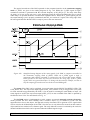
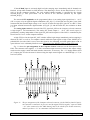
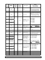
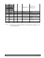
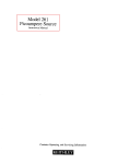
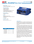
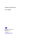
1
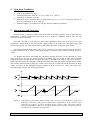
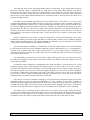
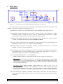
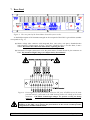
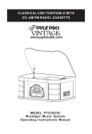
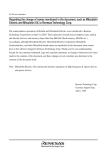
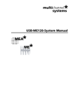
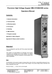
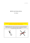
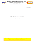
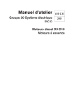
Piezo-Motor Controller (PMC)
SP 869
User's Manual
Physics Basel
Documentation Version 1.7, Mai 2006
PMC User's Manual (SP 869)
Physics Basel
Page 1 of 19
1. Safety Precautions
•
The Piezo-Motor Controller (PMC) is designed for indoors dry laboratory use by
qualified and authorized persons only.
•
Read this manual carefully before installing and using the PMC; all the safety
precautions must be respected!
•
ATTENTION: During operation lethal voltages up to ±400 V are present at the
connector HV_out[0..7] (to piezo-motors) on the rear-panel of the PMC.
•
ATTENTION: At the slip-stick piezo-motors and its interconnections lethal voltages
up to ±400 V are present during motion.
•
For wiring the HV_out[0..7] connector to the slip-stick piezo-motors, shielded and
isolated cables which are specified for this high voltage application must be used.
•
Never connect or disconnect any cables during operation; make sure all cables are
tightly connected and fixed by the bolts.
•
Do not open the PMC main-housing since lethal voltages are present inside. Service
and adjustments can be carried out only by the manufacturer.
•
Don't cover the cooling slots at the bottom and on the rear-panel.
•
Do not operate the PMC or the slip-stick piezo-motors in explosive atmospheres. The
PMC does not provide any explosion protection from static discharges or arcing
components.
•
Always switch off and disconnect the mains cable of the PMC at least for two minutes
before disconnecting/connecting the HV_out[0..7] connector or touching the slip-stick
piezo-motors or the wiring cables.
2. Disclaimer
Physics Basel hereby disclaims all responsibility for personal injury, property damage,
fine or penalty which results from misuse, not respecting the safety precautions, improper
maintenance or improper application of this product.
Compliance with all applicable environment and personnel safety regulations is the
sole responsibility of the user.
PMC User's Manual (SP 869)
Physics Basel
Page 2 of 19
3. Key Specifications
Channels:
Eight individual channels for forward and backward motion; only
one channel can be activated at the same time. The channels are
arranged in three groups: two groups with 3 axis and one group with 2
axis. Idle channels are short cut to GND via 47 Ohm resistors.
Output Voltage:
±0 V ... ±400 V saw-tooth with respect to common GND (minimum
±20 V for proper waveform)
1 μs back-jump (slip) rise/fall time (for load capacitance < 10 nF).
Stepping Frequency Range: ca. 1 Hz... 4'000 Hz (Load capacitance < 5 nF)
ca. 1 Hz... 2'000 Hz (Load capacitance < 10 nF)
ca. 1 Hz... 1'300 Hz (Load capacitance < 15 nF)
Load Capacitance Range:
0 nF... 15 nF
Hand-Control Unit:
- 6 push buttons for three axis (±x, ±y, ±z)
- Three position group switch (1, 2, 3)
- Two potentiometers for frequency and voltage adjustment
- Ergonomic housing for one hand manipulation
- Optical reflex photo sensor to activate the Hand-Control Unit
- 4 m cable length
Protection:
Overcurrent and Overheat (indicated by LED and beeper)
Mains Voltage:
85...264 VAC, 50 Hz / 60 Hz
Mains Fuse:
1.6 A slow blow, 5 mm x 20 mm
Power consumption, PFC:
70 W maximal, PFC according to IEC/EN 61000-3-2, Class A
Housing:
Desktop, Cooling-slots at bottom and rear-panel
Overall Size:
Width = 343 mm
Height = 95 mm
Depth = 310 mm (Without handles: 265 mm)
Weight:
ca. 4 kg
Additional Features:
- Individual selectable polarity for each channel
- Passive air cooled (no fans)
- Status LEDs on frontpanel
- Analog meter for indication of the high voltage (HV) on frontpanel
- HV-output connector 25 pin D-sub compatible with MSCU from
the company Omicron Nanotechnology GmbH
- Audible step
PMC User's Manual (SP 869)
Physics Basel
Page 3 of 19
4. Operation Conditions
•
•
•
•
•
Indoors dry laboratories only!
Ambient temperature between 5 °C (41 °F) and 40 °C (104 °F).
Altitude up to 2'000 m (6'561 ft).
Maximum relative humidity 80% for temperatures up to 31 °C (88 °F), decreases linearly to
50% at a temperature of 40 °C (104 °F).
Pollution degree 1 (no pollution or only dry and non conductive pollution).
5. Introduction and Overview
The Piezo-Motor Controller (PMC) offers the flexible and robust operation of up to eight slip-stick
piezo-motors. It allows a bidirectional movement in up to eight axis (channels), whereas only one axis
can be driven at the same time.
The PMC can drive a wide range of piezo-motor-capacitances from zero up to 15 nF. For load
capacitances smaller than 10 nF the sawtooth output voltage of the PMC has a fast back-jump (slip)
rise/fall time of only 1μs. This leads to efficient and reliable operation of slip-stick piezo-motors.
The applied sawtooth high voltage (HV) can be varied in a wide range from zero (minimum ±20 V
for proper waveform) up to ±400 V; the output voltage is referred to one common GND for all piezomotors.
For flexible and precise positioning the continuous stepping frequency can be adjusted in a large
range from about one step per second (1 Hz) up to 4'000 steps per second (4 kHz). The maximum
stepping frequency depends on the total load capacitance connected to the PMC; it is given by the piezomotor-capacitance plus the capacitance from the interconnection cable. For total load capacitances smaller
than 5 nF the whole frequency range up to 4 kHz can be used, for 10 nF the maximum frequency is about
2 kHz, and for 15 nF the maximum frequency shrinks to about 1.3 kHz. Fig. 1 shows two typical HV
sawtooth output voltages with different parameters.
Figure 1: Two different sawtooth HV output voltages (HV_out) with varied amplitudes, frequencies
and slopes (directions). The upper waveform has an amplitude of ±100 V and the slope
(direction) is negative; the lower waveform shows a positive slope (direction) with the
maximum amplitude of ±400 V. In both diagrams the fist part shows a single-step and the
second part the continuous stepping mode.
PMC User's Manual (SP 869)
Physics Basel
Page 4 of 19
The PMC has only one HV sawtooth generator which is followed by an HV output channel selector
where the sawtooth voltage is multiplexed (via eight relays) to the eight output channels. Non driven
piezo-motors are short cut to GND via 47 Ohm resistors. If the PMC isn't used for longer than four
seconds, the last used HV output channel is also deactivated; now the PMC is in the idle state. This means
that all relays of the output channel multiplexer are switched off and so all piezo-motors are short cut to
GND via 47 Ohm resistors.
The PMC can be manually operated by the remote Hand-Control Unit (HCU) or it can be easily
controlled and monitored via the built-in Computer-Control (CC) interface. This is normally attached to a
computer equipped with a digital (TTL) or mixed analog/digital interface-card. Under all conditions, the
HCU has the highest priority and signals from the CC interface are immediately interrupted if the HCU
gets activated. The HCU is activated by a finger of the operator which has to be placed at the bottom of
the HCU; the presence of the finger is detected by an optical reflex photo sensor. The HCU is connected
to the PMC via a four meter long flexible cable. To store the HCU in a save place it comes with a wallmount holder.
When a push-button on the HCU is pressed a single-step is carried out immediately; if the same
push-button remains pressed for longer than half a second the PMC switches to the continuous stepping
mode with the selected frequency. Also during stepping it is allowed to vary the frequency as well as the
voltage by the potentiometers on the frontpanel of the HCU.
The sawtooth polarity (NORMAL or INVERTED) of each HV output channel can be set individually
by DIP-switches on the rear-panel. NORMAL means that a positive push button (e.g. +x) corresponds to a
sawtooth with a positive slope and a negative push button (e.g. -x) to a negative-slope; if INVERTED is
selected this relation is reversed. This option allows the user to adjust the PMC to his sense of wiring and
motion of the piezo-motors.
For compatibility reasons the 25 pin D-sub HV output connector (HV_out to the piezo-motors) has
the same pin assignment as the 'Micro Piezo Slide Control Unit (MSCU)' from the company Omicron
Nanotechnology GmbH.
A fold-back current limitation is implemented in the PMC and allows a save operation over a wide
stepping-frequency range. If the maximum HV output current of 25 mA at ±400 V (12.5 mA at ±200 V)
is reached, the fold-back current limitation is activated and reduces the HV output voltage. Stepping is
still allowed and the user has just to reduce the stepping frequency to leave this overcurrent condition.
Overcurrent is indicated by the blinking red LED on the PMC (Overcurrent) as well as on the HandControl Unit (Failure); further an intermittent beeping is generated by the PMC. The PMC will not be
damaged by this overcurrent condition and no fuse will blow.
If the device is forced to continuous ramping for a long time near its maximum output power (at the
maximum frequency given by the load capacitance), it may overheat. If the PMC overheats it
automatically stops ramping and disables the HV until it has cooled down again. During overheat the red
warning LED on the PMC (Overheat) is turned on and the unit starts beeping. Further more, on the HandControl Unit the red LED (Failure) lights up. There is no damage to the PMC due to this overheating.
The PMC comes in a desktop housing with passive air cooling via slots at the bottom and on the
rear-panel. The bumper-feet at the bottom allow a good air circulation inside the housing and they must
not be removed. If the PMC has to be mounted in a 19"-rack, an optional rack-mount kit is available;
nevertheless make sure that the cooling-slots at the bottom and on the rear-panel aren't covered.
PMC User's Manual (SP 869)
Physics Basel
Page 5 of 19
6. Front-Panel
Figure 2: Front-panel top view of the Piezo-Motor Controller (not to scale).
The main elements to operate the PMC are arranged on the front-panel. A detailed description of all
elements is given below (number corresponds to Fig. 2):
(1) Main power switch. ON is also indicated by the white backlight of the analog meter (4)
(2) Connection to the Hand-Control Unit (HCU). Female D-sub 9 pin connector on PMC.
Proprietary interface which can only be used for communication with the HCU. Before
connecting/disconnecting the HCU switch off the main power switch.
(3) Bidirectional digital Computer-Control (CC) Interface (TTL). Female D-sub 37 pin connector
on PMC. See detailed description in chapter Computer-Control.
(4) Analog meter for indication of the applied HV of the sawtooth. Only a rough reading (error
about ±20%). Scale 0... 10 => ±0... ±400 V sawtooth amplitude.
(5) Status display: Ready (CC) = LED green, Ramping = LED yellow, Overcurrent = LED red
blinking / Overheat = LED red continuous.
(6) Piezo beeper for audible user information. A click for each piezo-motor step and a short beep if
the Hand-Control Unit gets activated (finger at the bottom of the HCU). Overcurrent =
intermittently beeping / Overheat = continuous beeping).
(7) Analog input/output signals 0... +10 V(LEMO 00):
(Mating LEMO connectors: Crimp: FFS.00.250.CTCE31, Solder: FFA.00.CTAC29)
HV set input: The HV of the sawtooth (±0... ±400 V) can be programmed by an analog input
voltage from 0 V to +10 V. Input resistance is > 30 kOhm. This analog input control is only
active if the TTL signal AD_SEL on the Computer-Control connector is high; otherwise the
HV is digitally programmed.
HV actual output: Analog read-back output voltage in a range of 0 V to +10 V
corresponding to the actual HV of the sawtooth (±0... ±400 V). The connected divce must
have an input resistance of > 10 kOhm. This analog output is steadily working independent
of the AD_SEL signal and of the PMC-control mode (by HCU or via the computer interface).
(8) 4 mm banana-jack grounding connection to the housing of the PMC. The PMC housing is
already grounded via the mains cord; there is no need to ground it by this 4 mm banana-jack
connector.
PMC User's Manual (SP 869)
Physics Basel
Page 6 of 19
7. Rear-Panel
Physics Basel
SN 08690000002
Made in Switzerland
Figure 3: The rear-panel of the Piezo-Motor Controller (not to scale).
A detailed description of all elements arranged on the rear-panel of the PMC is given below (number
corresponds to Fig. 3):
(1) Mains voltage inlet connector with integrated fuses (one active, one spare). Standard mains
inlet connector. Voltage range: 85 VAC...264 VAC, 50/60 Hz. Fuse: 1.6A slow blow, 5 mm x
20mm. Disconnect the PMC from mains before replacing the fuse!
(2) Sawtooth HV output connector to wire the piezo-motors. Female D-sub 25 pin connector on
PMC. Pay attention: High Voltage (see chapter Safety Precautions)!
Figure 4: Pin assignment of the piezo-motors connector (HV_out). All GNDs are on the same
potential and are connected to the PMC housing and to the shield of the D-sub
connector. CAUTION: Lethal high voltages are present on HV_out during
ramping!
To prevent flashovers at the piezo-motors and its interconnections and consequential
damages to the PMC, never operate the piezo-motors in the corona vacuum pressure
range between 10 mbar and 10-3 mbar.
PMC User's Manual (SP 869)
Physics Basel
Page 7 of 19
(3) Selection of the desired (NORMAL/INVERTED) sawtooth polarity for each of the eight HVoutput channels (see Fig. 5). Programmed via the octal DIP switch (Sawtooth Polarity):
Figure 5: Shows the direction (POS or NEG) and the corresponding shape of the HV sawtooth
for both the NORMAL and the INVERTED switch position. The mechanical
movement of a piezo-motor can easily be reversed by switching the corresponding
switch to the INVERTED position.
(4) 4 mm banana-jack grounding connection to the housing of the PMC. The PMC housing is
already grounded via the mains cord; there is no need to ground it by this 4 mm banana-jack
connector.
(5) Cooling slots. Do not cover!
(6) Serial number of the PMC.
PMC User's Manual (SP 869)
Physics Basel
Page 8 of 19
8. Hand-Control Unit (HCU) SP 869a
The PMC Hand-Control Unit (HCU) is connected to the PMC via a flexible four meter long cable.
Make sure that the PMC is always switched off before connecting or disconnecting the HCU. To activate
the HCU insert your forefinger inside the light shielding clip at its bottom. Then the optical reflex photo
sensor will trigger and the green LED Ready on the HCU will be turned on. The top view of HCU is
shown in Fig. 6 and detailed description of the numbered elements is given below:
(1) Six push-buttons for bidirectional movement in three
axes (±x, ±y, ±z). A single step is carried out
immediately after pressing one of the push-buttons;
continuous stepping is reached by pressing the same
button for longer than half a second.
(2) To address the eight channels in total, three different
groups (1, 2, 3) can be selected by a toggle switch. Group
1 and 2 provide three axes each (±x1, ±y1, ±z1 and ±x2,
±y2, ±z2) and the group 3 provides two axes (±x3, ±y3).
(3) Voltage potentiometer to adjust (linearly) the amplitude
of the sawtooth voltage in a range of ±0 V... ±400 V. A
minimum and a maximum high voltage can be
programmed by two pluggable resistors inside the HCU.
At shipping these two resistors are zero which
corresponds to the full amplitude range of
±0 V... ±400 V. Further details see the chapter 8.1
Disassembly of the HCU section A).
(4) Frequency potentiometer to adjust the repetition
frequency nonlinear in the range of about 1 Hz up to the
maximum frequency of normally 4 kHz. It can be
reduced by the trimmer fmax (5).
Figure 6: Top view of the PMC HandControl Unit (not to scale).
(5) Trim-potentiometer to adjust the maximum repetition frequency (fmax ) from about 100 Hz
(ccw) to max. 4 kHz (cw). At shipping the maximum repetition frequency of 4 kHz is adjusted.
(6) LEDs to display the status of the PMC on the HCU. Ready = LED green: During Ramping the
LED Ready is turned off. Failure = LED red: Overcurrent = Red LED is blinking, Overheat =
red LED is continuously turned on.
(7) Thru a drilling on the rear-side of the HCU the optical reflex photo sensor can detect objects
outside its housing. To prevent from wrong switching due to ambient light or placing the HCU
on a white table, the drilling is covered by a light shielding clip. Nevertheless, strong direct
light to the bottom of the HCU can unintentionally activate it. If a finger covers the sensordrilling at the bottom of the HCU, it gets activated. The green LED Ready on the HCU is
turned on and the green LED Ready (CC) on the PMC is turned off. The sensitivity of the
optical reflex sensor can be adjusted by a trimmer inside the HCU. Further details see the
chapter 8.1 Disassembly the of the HCU section B).
(8) Robust and flexible four meter long interconnection cable to the PMC; the shielded cable has
an outer diameter of 5 mm and a male 9 pin D-sub connector at its end.
PMC User's Manual (SP 869)
Physics Basel
Page 9 of 19
8.1 Disassembly of the HCU
Before starting to disassemble the HCU, switch the PMC off and disconnect the cable from the
PMC main unit!
Fig. 7 shows the sequence to open the HCU: First remove the gray and red caps on the adjusting
knobs (Frequency, Voltage); then loose the two knob-screws below them to detract the knobs. Next
unscrew the two hexagonally nuts of the potentiometer which were hidden by the two knobs (photo 2).
Then remove the four outer screws on the rear-side of the HCU; do not unscrew the light shielding clip
(photo 3). Now lift off the front-panel of the HCU to get access to the printed circuit board (photo 4).
Fig. 8 shows a zoomed view to the elements which can be adjusted or replaced.
To reassemble the HCU follow the instructions above in reversed sequence.
Figure 7: The sequence to open the HCU. First remove the two knobs of the potentiometers
before removing the four screws at the bottom; do not unscrew the light shielding clip.
PMC User's Manual (SP 869)
Physics Basel
Page 10 of 19
A) Adjusting the HV-Range of the HCU:
The range of the sawtooth high voltage (HVmin to HVmax), which is adjustable by the
potentiometer on the HCU, can be hard-programmed by two pluggable resistors inside the HCU. At
shipping these two resistors are zero, which gives the full possible amplitude range of
±0 V... ±400 V. Due to voltage restrictions given for example by the ceramic-material of the piezomotors, it may be necessary to limit the possible voltage range. The values (in Ω) of these two rangeresistors Rmin (sets HVmin) and Rmax (sets HVmax) are given by the following equations:
⎛ 400V ⎞
⎜
⎟
HV max ⎠
⎝
R min = 10kΩ
400V ⎞
⎛ 400V
−
⎜
⎟
⎝ HV min HV max ⎠
⎛ 400V
⎞
R max = (10kΩ + R min )⎜
− 1⎟
⎝ HV max ⎠
HVmax is the desired maximum peak sawtooth voltage. HVmin is the desired minimum peak
sawtooth output voltage; if a HVmin of 0 V is demanded the resistor Rmin must be zero. The resistors are
standard 0.5 W film resistors (1%, DIN0207) with a 10.16 mm folding.
By installing these two resistors only the sawtooth output voltage which can be
adjusted by the HCU, is restricted. Via the computer interface still the full output
voltage range of ±0 V... ±400 V is programmable!
B) Adjusting the Optical Sensor Sensitivity:
The sensitivity of the optical reflex sensor (finger detection) can be adjusted by a trimpotentiometer inside the HCU (see Fig. 8). To increase its sensitivity turn the trim-potentiometer
(Optical Sensor Sensitivity) clockwise. Normally a re-adjustment of the sensitivity is not necessary; if
there are problems with the optical reflex sensor, first clean the drilling and the optics from outside the
HCU.
Figure 8: A zoomed view to the section of the HCU printed circuit board with the marked
elements which can be adjusted or changed. The two white elements (Rmin, Rmax) are
zero-Ohm resistors which are installed at shipping.
PMC User's Manual (SP 869)
Physics Basel
Page 11 of 19
9. Computer-Control
The PMC has a built-in easy to use computer interface; it is based on parallel signals connected to a
computer via the 37pin Computer-Control (CC) connector on the front-panel of the PMC. As mentioned
before, the Hand-Control Unit (HCU) has the higher priority than signals from the CC-interface; signals
coming from the CC-interface are immediately interrupted and ignored if the HCU gets activated.
Figure 9: The simplified block diagram of the PMC and its interconnections to the outer world.
The Computer-Control connections are located on the left side and its signals make
interconnections to all of the three main blocks of the PMC.
Fig. 9 presents the simplified block diagram of the PMC. It shows how the simple computer interface
works with bidirectional digital TTL signals, and if needed also with analog 0... +10 V signals.
Via the dedicated digital signals the desired sawtooth HV amplitude (HV_D[0..7]), the channel
number (CH_No[0..2]), the moving direction (DIR) and the repetition frequency (CLK_SEL[0..2]) can be
selected. A single step or continuous stepping of the selected piezo-motor can be started by activating the
corresponding signal: S_STEP for a single step and C_STEP for continuous stepping. On the rising edge
of one of these start signals (S_STEP or C_STEP) the following CC-data are registered: CH_No[0..2],
DIR, SCRAM_SEL[0..3] and also the combination of the Sawtooth Polarity switch on the rear-panel.
During stepping, changes of these parameters are completely ignored. To modify these parameters, the
computer has first to deactivate the start signal (S_STEP or C_STEP), then alter the parameter(s), and
then turn on one of the start signals again.
The exact mapping of the signals CH_No[0..2], SCRAM_SEL[0..3], DIR etc. is shown in Fig. 12; it
gives a compressed overview of all digital I/O signals on the 37pin D-sub connector (Computer-Control).
PMC User's Manual (SP 869)
Physics Basel
Page 12 of 19
With the clock selection inputs (CLK_SEL[0..2]) seven different preprogrammed repetition
frequencies in the range of 15 Hz up to 1 kHz can be selected (the exact numbers can be found in the
table of Fig. 12). For variable and own-specific repetition frequencies all clock selection inputs
(CLK_SEL[0..2]) must be set to a high level (high if left unconnected). Now, the repetition frequency is
given by an external applied TTL clock signal (CLK_RAMP) in a range from 0.. 4.096 MHz; the sawtooth
repetition frequency is given by external clock frequency divided by 1'024.
The clock frequency as well as the HV amplitude (digital or analog) can be varied during stepping.
Fig. 10a shows a simplified timing diagram if the PMC is operated in the single step mode; the first
step is in positive direction and the second one in negative direction. The single step is triggered by the
rising edge of the S_STEP signal, the width of the S_STEP signal is unimportant.
The time delay (R_delay) between the rising edge of the start signal (S_STEP or C_STEP) and the
beginning of the ramp at the HV_out is normally about 16 ms. This delay of 16 ms occurs when the PMC
was idle, that means no channel-relay was active (after a pause of four seconds). If the same channel in
the same direction was used shortly before (within about four seconds) the time delay is 0 ms; this is
because there is no need to switch any relays. A time delay of about 24 ms is observed if the last used
channel is still active (earlier than four seconds) and a change in the direction is demanded. The delay
times are implemented to certainly start the ramping after the switching and bouncing of the channel
relays (block HV-Output Channel Selector in Fig. 9).
Figure 10a: Simplified timing diagram of the main signals if the PMC is computer-controlled in
the single step mode (S_STEP). Notice that the data specified in the most top trace are
stored on the rising edge of the S_STEP signal and are ignored thereafter.
PMC User's Manual (SP 869)
Physics Basel
Page 13 of 19
The typical waveforms of the PMC operated via the computer interface in the continuous stepping
mode (C_STEP) are given in the timing diagram of Fig. 10b. While the C_STEP signal is high a
continuous sawtooth is generated with the selected frequency (CLK_SEL[0..2]). The relay time delay
(R_delay) of 16 ms occurs only once, at the beginning when the selected channel-relay has to switch;
other delays are possible under the circumstances explained above. When the C_STEP signals gets low
the actual running cycle is properly terminated (until HV_out reaches 0 V again). The rising edge of the
READY signal indicates that the PMC is ready to process the next instruction.
Figure 10b: Simplified timing diagram of the main signals if the PMC is computer-controlled in
the continuous stepping mode (C_STEP). While the C_STEP signal is high, a
continuous and seamless sawtooth is generated on the selected HV output channel.
Data specified in the most top trace are stored on the rising edge of the C_STEP
signal; those are ignored thereafter. To change the direction for example, one has to
stop the ramping first and restart it with the inverted DIR signal.
The status of the PMC can be read-back via several status-signals (READY, RAMPING, OVR_CUR,
OVR_HEAT, HC). The step-count output signal (STEP_CNT) releases a 64 μs long positive TTL pulse
for each sawtooth step generated by the PMC; it can be used for counting the total number of steps. All
status signals as well as the step-count output (STEP_CNT) are also available if the PMC is operated by
the Hand-Control Unit. For more details see Fig. 12.
This SCRAM option is implemented to easily connect an external approach security electronics,
which prevents the user from colliding with a sensitive object (e.g. a cantilever). If the user has
approached too close to this object, the approach security electronics has to generate a TTL signal which
can be wired to the SCRAM input of the PMC. Now the user is only allowed to retract from the sensitive
object until he has reached a save distance again. The 'only allowed to retract' is realized by the exclusive
channel and direction which can be operated when the SCRAM signal is high.
PMC User's Manual (SP 869)
Physics Basel
Page 14 of 19
If the SCRAM input is activated (high level) the ramping stops immediately and all channels are
blocked, except ONE channel in ONE direction. This blocking is active for the Hand-Control Unit as
well as for the computer interface. The only enabled channel number is specified by the signals
SCRAM_SEL[0..2]. This piezo-motor can be moved in the direction specified by the signal
SCRAM_SEL[3].
The sawtooth HV amplitude can be programmed either via an analog input signal from 0... +10 V
(HV set input) or by an eight bit digital combination (HV_D[0..7]). If all 8 bits are low [00hex] (low if left
unconnected) the sawtooth high voltage is ±0 V and if all 8 bits are high [FFhex] the HV is ±400 V. There
is a linear relation between the digital number (HV_D[0..7]) and the actual HV; the resolution is about
1.57 V.
The analog input control is selected if the TTL signal AD_SEL on the Computer-Control connector
is high (high if left unconnected). The analog HV actual output 0... +10 V (HV actual output) is
permanently working independent of the signal AD_SEL and irrespective if the PMC is controlled by the
Hand-Control Unit or via the computer interface.
A high TTL level at the input HV_OFF switches off the high voltage immediately and no ramping is
allowed (by HCU as well as via computer control) while this input signal is high. If the /RESET pin is
pulled down (low) the PMC is reset; since this signal is also internally activated (pulled down with an
open collector or use a Schottky-Diode in series. Do not force the /RESET signal to a high TTL level.
Fig. 11 shows the pin assignment of the Computer-Control connector on the front-panel of the
PMC. The connector also supplies +5 V with a maximum output current of 100 mA; this output voltage
can be used to supply a small self-made interface electronics, if necessary. The +5 V supply and the GND
(0 V) output pins are also foreseen for direct wiring the input control signals to a defined high (+5 V) or
low level (GND).
Figure 11: The pin assignment of the Computer-Control connector. On the PMC a female 37pin Dsub connector is mounted. 32 pins are used for digital TTL I/O signals; 4 pins are GND
= 0 V (also connected to the PMC housing and to the shield of the D-sub connector);
and one pin drives +5 V at a maximum 100 mA load current.
PMC User's Manual (SP 869)
Physics Basel
Page 15 of 19
PIN #
of
DSUB37
Signal
Name
I/O
to/from
PMC
1
S_STEP
I
2
GND
Power
3
C_STEP
4
CH_No[0]
I
Input level
if
PIN left
open
0V = 0
Description
Single Step
Details
(Bold = Default /
Unconnected)
A Single Step is generated on the rising
edge.
The CH_No[0..2], DIR, SCRAM_SEL[0..3]
and the Sawtooth Polarity switch are
stored on the rising edge of S_STEP.
0V / Housing PMC
0V = 0
Continuous Steps
Continuous Steps are generated with the
sawtooth frequency (f_saw) while C_STEP
is HIGH.
The CH_No[0..2], DIR, SCRAM_SEL[0..3]
and the Sawtooth Polarity switch are
stored on the rising edge of C_STEP.
I
0V = 0
Channel Number of HV_out
(HV_out[0..7])
Stored on the rising edge of
S_STEP or C_STEP.
000: HV_out0 [x1]
001: HV_out1 [y1]
010: HV_out2 [z1]
011: HV_out3 [x2]
100: HV_out4 [y2]
101: HV_out5 [z2]
110: HV_out6 [x3]
111: HV_out7 [y3]
DIR
I
0V = 0
Direction (positive / negative
sawtooth)
Stored on the rising edge of
S_STEP or C_STEP.
0=POS / 1=NEG (Polarity = NORMAL)
Depends also on the Sawtooth Polarity
switch of the selected channel!
8
/RESET
I/O
5V = 1
Reset in/output
Open collector (pull down only, use an
Open-Collector or a Schottky-Diode in
series).
Active LOW
9
HV_OFF
I
0V = 0
Switch HV off
HV is switched off fast and no ramping is
allowed; also the Hand-Control is disabled.
10
SCRAM
I
0V = 0
SCRAM from external
approach security electronics.
SCRAM switches HV_out off immediately.
When SCRAM is HIGH, only ONE Channel
in ONE Direction can be activated
(specified by SCRAM_SEL[0..3])
11
SCRAM_SEL[0]
I
5V = 1
SCRAM Channel Number of
HV_out.
Only the selected Channel
Number is allowed when
SCRAM is activated.
Stored on the rising edge of
S_STEP or C_STEP.
111: Only HV_out7 allowed
110: Only HV_out6 allowed
:
001: Only HV_out1 allowed
000: Only HV_out0 allowed
I
5V = 1
SCRAM Direction (positive /
negative sawtooth).
Stored on the rising edge of
S_STEP or C_STEP.
0=POS / 1=NEG (Polarity = NORMAL)
Depends also on the Sawtooth Polarity
switch of the selected channel!
5V = 1
Ramp clock source selection
(variable f_saw via external
CLK_RAMP or fixed f_saw
from internal clock)
111: f_saw = CLK_RAMP / 1024
110: f_saw = ca. 1kHz fix
101: f_saw = ca. 500Hz fix
100: f_saw = ca. 250Hz fix
011: f_saw = ca. 125Hz fix
010: f_saw = ca. 62.5Hz fix
001: f_saw = ca. 31.3Hz fix
000: f_saw = ca. 15.6Hz fix
0V = 0
External clock for the
sawtooth
5
CH_No[1]
6
CH_No[2]
7
12
SCRAM_SEL[1]
13
SCRAM_SEL[2]
14
SCRAM_SEL[3]
15
CLK_SEL[0]
16
CLK_SEL[1]
17
CLK_SEL[2]
I
18
GND
Power
19
CLK_RAMP
I
20
GND
Power
21
AD_SEL
I
PMC User's Manual (SP 869)
0V /Housing PMC
f_saw = CLK_RAMP(0..4MHz) / 1024
0V / Housing PMC
5V = 1
Analog or Digital HV-set
Physics Basel
1=HV analog set / 0=HV digital set
Page 16 of 19
22
HV_D[0]
23
HV_D[1]
24
HV_D[2]
25
HV_D[3]
26
HV_D[4]
27
HV_D[5]
28
HV_D[6]
29
HV_D[7]
30
+5V/100mA
Power
31
READY
O
PMC is ready for a step
Active HIGH
32
RAMPING
O
PMC is ramping the HV_out
Active HIGH
33
STEP_CNT
O
A 64 μs pulse is generated at
the fast edge of sawtooth.
34
HC
O
Hand-Control selected
0=Computer-Control / 1=Hand-Control
35
OVR_CUR
O
Overcurrent at the HV_out
Active HIGH
Ramping (by HCU or S_STEP, C_STEP) is
still possible.
36
OVR_HEAT
O
Overheat of the PMC
Active HIGH
Ramping is disabled and HV is switched
off automatically.
37
GND
Power
Figure 12:
I
0V = 0
8bit digital HV-set value of the
sawtooth output voltage
0000'0000: HV = ±0V
:
1000'0000: HV = ±200V
1000'0001: HV = ±201.6V
:
1111'1111: HV = ±400V
+5V supply for external
circuits
max. 100mA (internal 200mA multifuse)
Pulse to count the number of steps (works
also if Hand-Control Unit is active)
0V / Housing PMC
The table with all I/O signals available on the Computer-Control connector. A short
description and some details are also given; for better and deeper explanations see the
chapter Computer-Control.
PMC User's Manual (SP 869)
Physics Basel
Page 17 of 19
10. Functional Principle of the PMC Electronics
The block diagram presented in Fig. 13 illustrates the entire inner life of the PMC inclusive the
Hand-Control Unit. It shows the functional principle of the PMC electronics and its interaction with the
controls and the analog and digital interface signals.
The complete PMC electronics is supplied by a 35 W switching power supply with a single output
voltage of 12.7 V. All other voltages needed for the electronics (+5 V, ±15 V), including also the variable
bipolar high voltage (±0 V... ±400 V), are generated locally on the printed circuit board via DC/DC
converters.
The positive (+Vs, 0 V... +400 V) and the negative high voltage (-Vs, 0 V... –400 V) are produced by
two high voltage DC/DC converters from the company EMCO. Two separate controller-circuits (HV
Supply Controllers) perform the regulation and the current limitation of each of the two high voltage
DC/DC converters. The set value of the high voltage is wired in parallel to both of the two HV Supply
Controllers, resulting in a symmetrical bipolar high voltage (HV) in a range of ±0 V... ±400 V.
The bipolar HV supply is connected to the HV-Power Stage where the high voltage and high speed
signals are generated and thereafter distributed via the HV-Output Channel Selector to the selected HV
output cannel (HV_out[0..7]).
The HV-Power Stage is a push-pull power stage formed by two high-speed, high-voltage n-channel
MOS-FETs with two high power 22 Ohm resistors in series. These two resistors limit the maximum peakcurrent during the very fast discharge of the load capacitance.
The two gates of the power MOS-FETs are driven by two transformers which perform a galvanic
isolation between the HV power stage and the driving circuit.
The following explanations are given for a positive sawtooth:
To generate the linear HV ramp, a 1 MHz square wave signal is amplitude modulated and then
transmitted via the transformer to gate of the 'loading' MOS-FET (upper MOS-FET). Thus the
capacitance at the HV output is continuously loaded by a vast series of small 1 MHz current pulses which
result in a fine stepped linear HV ramp at the output. To enable that this principle works for different load
capacitances and independent of the MOS-FET parameters, the linear ramp is generated by using a closed
feedback loop. The amplitude modulation is steered by a PI-Controller which gets the actual value of the
HV output via a Voltage Divider (÷200). The sawtooth reference signal is generated by a multiplying 10
bit DAC connected to a 10 bit counter located inside the PMC-Chip. The analog reference signal of the
multiplying DAC is derived from the actual HV amplitude. This scheme leads to a sawtooth DAC output
signal with an amplitude proportional to the adjusted HV.
When the linear ramp reaches its maximum positive output voltage (+Vs), a fast back-jump has to
discharges the loaded capacitance to the negative output voltage (-Vs) in a very short time (around 1 μs).
This is performed by an exactly timed discharge pulse feed to the gate of the 'discharge' MOS-FET (lower
MOS-FET). After the fast discharge the HV output voltage is linearly ramped again towards the positive
output voltage (+Vs). A single steps as well as continuous stepping, start and stop with a piezo-motor
output voltage (HV_out ) of zero volt.
For a negative HV ramp (piezo-motor moves in opposite direction) the principle works in the same
way but the functions of the MOS-FETs and some other circuits are swapped.
The complete sawtooth control logic, the relay logic and the computer interface are implemented
inside the PMC-Chip. The PMC-Chip is a programmable CPLD from the company ALTERA.
PMC User's Manual (SP 869)
Physics Basel
Page 18 of 19
Figure 13: Block diagram of the complete PMC electronics inclusive the Hand-Control Unit. Nearly the
complete logic of the PMC is implemented in the PMC-Chip, a programmable CPLD.
-z
-y
+y
3
5
Serial Data
Encoder
+V
1 3
+x
SER_KEY_DATA
Failure
(red)
+z
Retract
HCU Logic
-x
1
Ready
(green)
V_vco (+0.9 .. +4.1V)
Approach
HC
HC
green
RAMPING
HC_VT
SCRAM
HV_OFF
READY
STEP_CNT
Ramping
SCRAM_SEL[0..3]
DIR
CH_No[0..2]
Serial Data
Decoder
Ready
CLK_VCO
S_STEP
C_STEP
VCO
1kHz..4MHz
Page 19 of 19
4
C_S_HC
S_S_HC
C_S
S_S
HC
PMC-Chip
3
8
Polarity
Logic
Higher-Ranking
Control
Logic
3
Discharge
Pulse (4us)
CLK_R
CLK
Selection
C_1kHz
C_15kHz
CLK_1MHz
CLK
Divider
Sawtooth
Control
Logic
HC
3
1 MHz
Quartz
Oscillator
Relay Timer
&
Logic
BEEPER
LED_RED
RES_OUT
4
+5V/100mA
+5V
-15V
+15V
Overcurrent
Overheat
HV_OFF_int
red
REL[0..2]
REL_ENA
NEG
/RESET
OVR_HEAT
OVR_I
RESET
DIS
RAMP_DAC
[0..9]
NEG: +1
DC/DC
Converters
Audible Step
Acoustic Alarm
Rin
Housing
-OVR_I
+OVR_I
N
PE
L
HC
CC
HC
POS
Power
POS
1.6A slow
Fuse
HV actual output
[0..+10V]
-OVR_I
Mains
Inlet
Amp.
Voltage
Divider
(÷200)
Amp.
HV-Power
Stage
22R
22R
300k
POS
NEG
300k
85..264VAC
50/60Hz
-HV-Supply
Controller
+12.7V
-Vs (0..-400V)
S
D
S
D
HV DC/DC
Converter
0..-400V
G
G
+12.7V
V
HV of Sawtooth
[0..±400V]
+Vs (0..+400V)
HV DC/DC
Converter
0..+400V
+HV Supply
Controller
+Vs_mon (0..+4V)
V_HV (0 . .+2.55V)
Analog I/O Control
Signals
(via LEMO 00)
OVR_HEAT
Discharge
(4us)
+
D
A
Switching
Power Supply
35W
Σ
−
Modulator
(0..+2.55V)
+12.7V
+/- 1
POS: -1
HV set input
[0..+10V]
OVR_I
PI
Controller
DAC
(8 bit)
Reset
Generator
Rout
+5V
8
DAC multipl.
(10 bit)
+Vs_mon (0..+4V)
OVR_HEAT
OVR_CUR
AD_SEL
HV_D[0..7]
Piezo Motor Controller (PMC)
SP 869
DISABLE
Data Switch
DIGITAL I/O SIGNALS for Computer-Control
(via 37pin female D-SUB)
HC_DATA[0..3]
4
Automatic
Repetition
+5V
Vc_HV (0 .. +2.55V)
POL_SEL[0..7]
READY
HC_RED
HC_GREEN
64µs
C_1kHz
Remote Control
via a 4.5m cable
(via 9pin female D-SUB)
CLK_RAMP
CLK_SEL[0..2]
yellow
Rmax for
Vmax
Hand-Control
Unit (HCU)
SP 869a
HC Schmitt
Trigger
IR
Finger to
enabled HCU
HC_ANA
Voltage
HC
CC
HC
Frequency
HC_VT
C_1kHz
Vf_L
NEG
1 2 3
REL_STABLE
VV_H
C_1kHz
0.39
fmax
BUSY
Rmin for
Vmin
8 Polarity
Switches
HV_OFF_int
HV_OFF_int
2.5
Vf_H
HC
CLK_1MHz
4
+Vs
GND
HV_out0[x1]
HV_out1[y1]
HV_out2[z1]
HV_out3[x2]
HV_out4[y2]
HV_out5[z2]
HV_out6[x3]
HV_out7[y3]
GND
HV Sawtooth Signals
to the Piezo-Motors
(via 25pin female D-SUB)
-Vs
HC = Hand-Control (via HCU, SP 869a)
CC = Computer-Control (via 37pin D-SUB)
Decoder
8
Relay
Driver
8
(Relays)
HV-Output
Channel
Selector
Group
HC
CC
BUSY
10bit up/down
counter
S_WRONG
STEP_CNT
Data Source
Switch
C_15kHz
NEG
V_HV (0 .. +2.55V)
V_HV (0 .. +2.55V)
Physics Basel
SCRAM
Logic
bias
PMC User's Manual (SP 869)