1
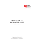
Copley
Controls
Corp.
Accelnet Micro Panel
™
DIGITAL SERVOAMPLIFIER
for BRUSHLESS or BRUSH MOTORS
Control Modes
• Indexer, Point-to-Point, PVT
• Camming, Gearing, Position, Velocity, Torque
Command Interface
• CANopen/DeviceNet
• ASCII and discrete I/O
• Stepper commands
• ±10V position/velocity/torque command
• PWM velocity/torque command
• Master encoder (Gearing/Camming)
Communications
• CANopen/DeviceNet
• RS232
Feedback
• Digital Quad A/B encoder
• Secondary encoder / emulated encoder out
• Digital Halls
I/O - Digital
• 9 inputs, 4 outputs
Dimensions: mm [in]
• 97 x 63 x 33 [3.8 x 2.5 x 1.3]
description
Accelnet Micro Panel is a compact, DC powered servo drive
for position, velocity, and torque control of AC brushless and
DC brush motors. It can operate on a distributed control network, as a stand-alone indexing drive, or with external motion
controllers.
Model
Ip
Ic
Vdc
ACJ-055-09
9
3
55
ACJ-055-18
18
6
55
ACJ-090-03
3
1
90
ACJ-090-09
9
3
90
ACJ-090-12
12
6
90
Indexing mode enables simplified operation with PLC’s which
use outputs to select and launch indexes and inputs to read
back amplifier status. Additionally, a PLC can send ASCII data
that can change motion profiles so that one index can perform
various motions as machine requirements change. DeviceNet
capability enables multiple Accelnet drives to be controlled
from PLC’s that use this communication protocol.
The CANopen distributed control architecture is also supported.
As a CAN node operating under the CANopen protocol, it supports Profile Position, Profile Velocity, Profile Torque, Interpolated Position, and Homing. Up to 127 drives can operate on
a single CAN bus and groups of drives can be linked via the
CAN so that they execute motion profiles together.
Operation with external motion controllers is possible in
torque (current), velocity, and position modes. Input command signals can be ±10V (torque, velocity, position),
PWM/Polarity (torque, velocity), or stepper format (CU/CD or
Step/Direction).
Copley Controls Corp., 20 Dan Road, Canton, MA 02021, USA
Web: www.copleycontrols.com
Tel: 781-828-8090 Fax: 781-828-6547
Page of 14
Copley
Controls
Corp.
Accelnet Micro Panel
™
DIGITAL SERVOAMPLIFIER
for BRUSHLESS or BRUSH MOTORS
GENERAL SPECIFICATIONS
Test conditions: Load = Wye connected load: 2 mH + 2 Ω line-line. Ambient temperature = 25°C, +HV = HVmax
MODEL
ACJ-055-09 ACJ-055-18 ACJ-090-03 ACJ-090-09 ACJ-90-12
Output Power
Peak Current
9 (6.36)
18 (12.73)
3 (2.12)
Peak time
1
1
1
Continuous current
3 (2.12)
6 (4.24)
1 (0.71)
Peak Output Power
490
970
270
Continuous “ “
163
323
89
Output resistance
0.075
0.075
0.075
Maximum Output VoltageVout = HV*0.97 - Rout*Iout
9 (6.36)
1
3 (2.12)
800
267
0.036
12 (8.5)
1
6 (4.24)
1600
533
0.075
Adc (Arms, sinusoidal), ±5%
Sec
Adc (Arms, sinusoidal), ±5%
W
W
Rout (Ω)
INPUT POWER
HVmin to HVmax
+20 to +55 +20 to +55 +20 to +90 +20 to +90 +20 to +90
Ipeak
9
18
3
9
12
Icont
3
6
1
3
6
Aux HV+20 to +HVmax @ 500 mAdc maximum
PWM OUTPUTS
Type
PWM ripple frequency
Vdc, Transformer-isolated
Adc (1 sec) peak
Adc continuous
3-phase MOSFET inverter, 15 kHz center-weighted PWM, space-vector modulation
30 kHz
DIGITAL Control
Digital Control Loops
Sampling rate (time)
Commutation
Modulation
Bandwidths
HV Compensation
Minimum load inductance
Current, velocity, position. 100% digital loop control
Dual loop position control using secondary encoder input
Current loop: 15 kHz (66.7 us) Velocity, position loops: 3 kHz (333 us)
Sinusoidal field-oriented control or trapezoidal from Halls for brushless motors
Center-weighted PWM with space-vector modulation
Current loop: 2.5 kHz typical, bandwidth will vary with tuning & load inductance
Changes in bus voltage do not affect bandwidth
200 µH line-line
command inputs
CANopen
Digital position
Digital torque & velocity
Analog torque/velocity/position Profile Position, Interpolated Position, Profile Velocity, Profile Torque, Homing
Step/Direction, CW/CCW
Stepper commands (2 MHz maximum rate)
Quad A/B Encoder
20 Mcount/sec (after quadrature), 5 Mline/sec
PWM , Polarity
PWM = 0~100%, Polarity = 1/0
PWM
PWM = 50% ±50%, no polarity signal required
PWM frequency range
1 kHz minimum, 100 kHz maximum
PWM minimum pulse width
220 ns
±10 Vdc, 5 kΩ differential input impedance
digital inputs
Number, type
All inputs
Logic levels
Pull-up, pull-down control
Enable [IN1]
GP [IN2,3,4]
MS [IN5]
HS [IN6,7,8,9]
9, non-isolated. [IN1] dedicated to Amp Enable function, [IN2]~[IN9] are programmable
74HC14 Schmitt trigger operating from +5 Vdc with RC filter on input
10 kΩ to +5 Vdc or ground for all except [IN5] (see below)
Vin-LO < 1.35 Vdc, Vin-HI >3.65 Vdc, Input voltage range 0 to +24 Vdc
All inputs have group selectable connection of input pull-up/down resistor to +5 Vdc, or ground
1 Dedicated input with 330 µs RC filter for amplifier enable
3 General Purpose inputs with 330 µs RC filter
1 Medium-Speed input for motor temperature switch, 33 µs RC filter, 4.99 kΩ pullup/pulldown
4 High-Speed Inputs inputs with 100 ns RC filter
digital outputs (NOTE 1)
Number, type
[OUT1~4]
Current rating
4, non-isolated, programmable
Current-sinking MOSFET with 1 kΩ pullup to +5 Vdc through diode
100 mAdc max, +30 Vdc max. Functions programmable
External flyback diode required if driving inductive loads
Copley Controls Corp., 20 Dan Road, Canton, MA 02021, USA
Web: www.copleycontrols.com
Tel: 781-828-8090 Fax: 781-828-6547
Page of 14
Copley
Controls
Corp.
Accelnet Micro Panel
™
DIGITAL SERVOAMPLIFIER
for BRUSHLESS or BRUSH MOTORS
MULTI-Mode encoder port
Operation
Signals
Receiver
Driver
Frequency
Motor encoder signals are buffered and appear on J5 for feedback to control system
Programmable to be quadrature encoder input for electronic gearing
A, /A, B, /B, X, /X
26C32 differential line receiver (for operation as an encoder input port)
26C31 differential line driver (for operation as buffered encoder outputs)
20 MHz (post-quadrature)
RS-232 PORT
Signals
Mode
Protocol
RxD, TxD, Gnd
Full-duplex, serial communication port for amplifier setup and control, 9,600 to 115,200 baud
Binary or ASCII formats
CAN PORTS
Signals
Isolation
Format
Data
Address selection
CANH, CANL, Gnd
CAN interface circuit and +5 Vdc supply for CAN is optically isolated from amplifier circuits
CAN V2.0b physical layer for high-speed connections compliant
CANopen Device Profile DSP-402
Programmable to flash memory or determined by digital inputs
motor connections
Phase U, V, W
Hall U, V, W
Encoder A, /A, B, /B, (X,/X)
Hall & encoder power
Motemp [IN 5]
Brake
PWM outputs to 3-ph. ungrounded Wye or delta wound brushless motors, or DC brush motors
Digital Hall signals, single-ended
Digital quadrature encoder signals, differential (X or Index signal not required)
5 MHz maximum line frequency (20 Mcounts/sec)
26C32 differential line receiver with 121 Ω terminating resistor between complementary inputs
+5 Vdc ±2% @ 250 mAdc max
Motor overtemperature sensor switch input
Programmable to disable amplifier when motor over-temperature condition occurs
[OUT1~4] are programmable for motor brake function, external flyback diode required
status indicators
Amp Status
CAN Status
Bicolor LED, amplifier status indicated by color, and blinking or non-blinking condition
Bicolor LED, status of CAN bus indicated by color and blink codes to CAN Indicator Specification 303-3
protections
HV Overvoltage
HV Undervoltage
Amplifier over temperature
Short circuits
I2T Current limiting
Motor over temperature
Functions
+HV > HVmax, Amplifier outputs turn off until +HV < HVmax (See Input Power for HV)
+HV < +14 Vdc, Amplifier outputs turn off until +HV > +14 Vdc
Heat plate > 70°C
Output to output, output to ground, internal PWM bridge faults
Programmable: continuous current, peak current, peak time
Digital inputs programmable to detect motor temperature switch
Fault conditions are programmable as latching or non-latching types
MECHANICAL & ENVIRONMENTAL
Size Weight
Ambient temperature
Humidity
Contaminants
Environment
Cooling
3.83 x 2.47 x 1.29 in. (97.28 x 62.74 x 32.77 mm)
4.8 oz, 0.14 kg
0 to +45 °C operating, -40 to +85 °C storage
0 to 95%, non-condensing
Pollution degree 2
IEC68-2: 1990
Conduction through heatplate on amplifier chassis, or convection
Copley Controls Corp., 20 Dan Road, Canton, MA 02021, USA
Web: www.copleycontrols.com
Tel: 781-828-8090 Fax: 781-828-6547
Page of 14
Copley
Controls
Corp.
Accelnet Micro Panel
™
DIGITAL SERVOAMPLIFIER
for BRUSHLESS or BRUSH MOTORS
CME 2™ SOFTWARE
CANopen Networking
Amplifier setup is fast and easy using CME 2™ software which
communicates with the amplifier over CAN or an RS-232 link. All
of the operations needed to configure the amplifier are accessible
through this powerful and intuitive program. Auto-phasing of
brushless motor Hall sensors and phase wires eliminates “wire
and try”. Connections are made once and CME 2™ does the rest
thereafter. Encoder wire swapping to establish the direction of
positive motion is eliminated.
Based on the CAN V2.0b physical layer, a robust, two-wire communication bus originally designed for automotive use where lowcost and noise-immunity are essential, CANopen adds support for
motion-control devices and command synchronization. The result
is a highly effective combination of data-rate and low cost for
multi-axis motion control systems. Device synchronization enables
multiple axes to coordinate moves as if they were driven from a
single control card.
Motor data can be saved as .ccm files. Amplifier data is saved as .ccx
files that contain all amplifier settings plus motor data. This eases
system management as files can be cross-referenced to ampifiers.
Once an amplifier configuration has been completed systems can
be replicated easily with the same setup and performance.
RS-232 communications
CAN status LED
The CAN status LED operates in accordance with CAN specification 303-3. This is a bi-color LED that uses red and green colors
in solid, flashing, and blinking states to indicate conditions on the
CAN bus.
The serial-port is three-wire (RxD,TxD, Gnd), full-duplex RS-232
that operates from 9600 to 115,200 Baud. Connections to the
RS-232 port are through J5, the Signal connector. The Accelnet
Micro Panel Serial Cable Kit (ACJ-SK) contains a 9-pin female SubD serial port (COM1, COM2, etc.) connector and 2m (6 ft.) cable
that is terminated in a J5 cable connector. This provides an easy
connection to the amplifier for set-up without wiring to J5.
AMP status LED
A bi-color LED gives the status of the amplifier by changing
color, and either blinking or remaining solid. The possible
color and blink combinations are:
•Green/Solid: Amplifier OK and enabled. Will run in
response to reference inputs or CANopen commands.
•Green/Slow-Blinking: Amplifier OK but NOT-enabled.
Will run when enabled.
Status LEDS
•Green/Fast-Blinking: Positive or Negative limit switch
active. Amplifier will only move in direction
not inhibited by limit switch.
•Red/Solid: Transient fault condition.
Amplifier will resume operation when
fault is removed.
•Red/Blinking: Latching fault. Operation will
not resume until amp is Reset
Fault conditions:
• Over or under-voltage
34!453
,%$
#!.
,%$
• Motor over-temperature
• Phasing error (current position
is > 60° electrical from Hall angle)
• Short-circuits from output to output
• Short-circuits from output to ground
• Internal short circuits
• Amplifier over-temperature
• Position-mode following error
Faults are programmable to be either
transient or latching
Copley Controls Corp., 20 Dan Road, Canton, MA 02021, USA
Web: www.copleycontrols.com
Tel: 781-828-8090 Fax: 781-828-6547
Page of 14
Copley
Controls
Corp.
Accelnet Micro Panel
COMMAND Inputs in
Stand-Alone Mode
™
Current or Velocity Mode
Reference Inputs
The command inputs control the amplifier to
produce an output and are used when the
amplifier is taking current, velocity, or position
commands from an external controller in standalone mode. The command inputs take digital
and analog signals in a variety of formats:
PWM/Direction Inputs
Duty = 0~100%
[IN7]
[IN8]
Current or Velocity Mode
±10V Analog
DIGITAL SERVOAMPLIFIER
for BRUSHLESS or BRUSH MOTORS
Step Motor Emulation Inputs
Pulse/Direction Inputs
Pulse
Current or
Velocity
[IN7]
[IN8]
Direction
Polarity or
Direction
Position
magnitude
Position
Increment or
Decrement
PWM/Direction
PWM 50%
Count-up/Count-down Inputs
PWM 50% Input
Position Mode
CU/CD
Duty = 50% ±50%
[IN7]
Step/Direction
±10V Analog
Master Encoder
<no connection>
[IN8]
Current or
Velocity
CW (or CU)
[IN7]
CCW (or CD)
[IN8]
No function
Position
Increase
Position
Decrease
A/B Quadrature
For current or velocity control, the PWM/Direction format takes a PWM signal at constant
frequency which changes its’ duty cycle from
0 to 100% to control current or velocity and
a DC level at the Direction input to control
polarity. The PWM 50% format takes a single
PWM signal that produces 0 output at 50%
duty cycle, and maximum positive/negative
outputs at 0% or 100%. As a protection against
wiring faults, the 0% and 100% inputs can be
programmed to produce 0 output. When this
is done the max/min duty cycle range is >0%
and <100%.
Quad AB Encoder
±10 V Analog Input
Ref(+)
37.4k
5.36k
Ref(-)
37.4k
Pos++
5k
Pos--
Ch. A
Ch. B
+
A
5k
+ 1.5V
-
ENC
B
[IN8]
[IN7]
Master Enc.
Ch. A
Master Enc.
Ch. B
Position-control inputs take signals in popular
stepper-motor format or from a digital quadrature encoder. The CU/CD format moves the motor in a positive direction for each pulse
received at the count-up input. Negative motion is produced by pulses on the count-down input. The step-direction mode moves the
motor an increment of position for every pulse received at the pulse input while the direction of movement is controlled by a DC level
on the direction input.
Master encoder quadrature signals (A,B) are decoded into four counts per encoder line with the direction derived from the logic-state
transitions of the inputs. In position mode the ratio of motor motion per input-count is programmable.
A ±10V analog command can control current, velocity, or position as well.
multi-MODE ENCODER PORT
This port consists of three differential input/output channels with
functions programmable.
Functional diagram
of one channel
For dual-loop position-mode operation that employs a primary
encoder on the motor, and a secondary encoder on the load,
the port works as an input receiving the secondary encoder’s
quad A/B/X signals.
For stand-alone operation with an external motion controller, the
signals from the digital encoder on the motor are buffered and
made available at the control signal connector for transmission
to the controller. This eliminates split-wired motor cables with
dual connectors that take the encoder signals to both amplifier
and controller.
Copley Controls Corp., 20 Dan Road, Canton, MA 02021, USA
Web: www.copleycontrols.com
Tel: 781-828-8090 Fax: 781-828-6547
Page of 14
Copley
Controls
Corp.
Accelnet Micro Panel
™
DIGITAL SERVOAMPLIFIER
for BRUSHLESS or BRUSH MOTORS
digital INPUTS
has nine digital inputs, eight of which have programmable functions. Input [IN1] is not programmable and is
dedicated to the amplifier Enable function. This is done to prevent accidental programming of the input in such a way that the controller
could not shut it down.
Two types of RC filters are used: GP (general purpose) and HS (high speed). Input functions such as Step/Direction, CU/CD, Quad A/B
are wired to inputs having the HS filters, and inputs with the GP filters are used for general purpose logic functions, limit switches, and
the motor temperature sensor. Programmable functions of the digital inputs include :
•
•
•
•
•
•
Positive Limit switch
• Step & Direction, or CU/CD
Negative Limit switch step motor position commands
Home switch
• Quad A/B master encoder
Amplifier Reset position commands
PWM current or velocity commands
• Motor over-temperature
CAN address bits
In addition to the active level and function for each programmable input, the input resistors are programmable in three groups to either
pull up to +5 Vdc, or down to ground. Grounded inputs with HI active levels interface to PLC’s that have PNP outputs that source current
from +24 Vdc sources. Inputs pulled up to +5 Vdc work with open-collector, or NPN drivers that sink current to ground.
GP Inputs 4,5
GP Inputs 1,2,3
24 Vdc max
[IN1]
[IN2]
[IN3]
+5V
10k
24 Vdc max
Programmable
1/0
+5V
10k
* 4.99k
74HC14
Programmable
1/0
74HC14
[IN4]
*[IN5]
10k
10k
* [IN5] connects to J4 for
motor temperature sensor
33nF
33nF
*3.3nF
HS Inputs 6,7,8,9
5 Vdc max
+5V
[IN6]
10k
Programmable
1/0
74HC14
[IN7]
[IN8]
[IN9]
1.0 k
100 pF
+5V
DIGITAL OUTPUTS
Digital outputs are open-drain MOSFETs with 1 kΩ pull-up resistors to +5 Vdc. These can
sink up to 100 mAdc from external loads operating from power supplies to +30 Vdc. When
driving inductive loads such as a motor brake, an external fly-back diode is required. The
diode in the output is for driving PLC inputs that are opto-isolated and connected to +24
Vdc. The diode prevents conduction from +24 Vdc through the 1 kΩ resistor to +5 Vdc in
the amplifier. This could turn the input on, giving a false indication of the amplifier output
state.
These outputs are programmable to be on or off when active. Typical functions are amplifier
fault indication or motor brake operation. Other functions are programmable.
Copley Controls Corp., 20 Dan Road, Canton, MA 02021, USA
Web: www.copleycontrols.com
Tel: 781-828-8090 1k
[OUT1]
[OUT2]
[OUT3]
[OUT4]
Fax: 781-828-6547
Page of 14
Copley
Controls
Corp.
Accelnet Micro Panel
™
DIGITAL SERVOAMPLIFIER
for BRUSHLESS or BRUSH MOTORS
MOTOR CONNECTIONS
Motor connections are of four types: phase, Halls, encoder and thermal sensor. The phase connections carry the amplifier output
currents that drive the motor to produce motion. The Hall signals are three digital signals that give absolute position feedback
within an electrical commutation cycle. The encoder signals give incremental position feedback and are used for velocity and
position modes, as well as sinusoidal commutation. A thermal sensor that indicates motor overtemperature is used to shut down
the amplifier to protect the motor.
+5V
Motor Temperature Sensor
Digital input [IN5] is for use with a motor overtemperature switch. The
input should be programmed as a pull-up to +5 Vdc if the motor switch is
grounded when cold, and open or high-impedance when over-heating.
4.99 k
74HC14
10 k
[IN5]
3.3 nF
MOTOR ENCODER
The input circuit for the motor encoder signals is a differential line-receiver
with R-C filtering on the inputs. A 121 Ω resistor is across each input pair
to terminate the signal pairs in the cable characteristic impedance. The
circuit is shown below. Encoders with differential outputs are required
because they are less susceptible to noise that can be picked on singleended outputs. For best results, encoder cabling should use twisted pair
cable with one pair for each of the encoder outputs: A-/A, B-/B, and X-/X.
Shielded twisted-pair is even better for noise rejection.
22 pF
+5V
2k
1k
A, B, X
ENC
/A, /B, /X
121
1k
MOTOR HALL SIGNALS
U
W
HALL
26LS32
22 pF
+5V
V
Hall signals are single-ended signals that provide absolute feedback within
one electrical cycle of the motor. There are three of them (U, V, & W) and
they may be sourced by magnetic sensors in the motor, or by encoders
that have Hall tracks as part of the encoder disc. They typically operate at
much lower frequencies than the motor encoder signals, and are used for
commutation-initialization after startup, and for checking the motor phasing
after the amplifer has switched to sinusoidal commutation.
+
10 k
10 k
U, V, W
74HC14
3.3 nF
+5 Vdc
Motor Brake
Digital outputs [OUT1,2,3,4] can be programmed to power a motor-mounted
brake. These brake the motor when they are in an unpowered state and
must have power applied to release. This provides a fail-safe function that
prevents motor motion if the system is in an unpowered (uncontrolled)
state. Because brakes are inductive loads, an external flyback diode must
be used to control the coil voltage when power is removed. The timing of
the brake is programmable.
[OUT1] [OUT2]
[OUT3], or [OUT4]
motor phase connections
+HV
Input
The amplifier output is a three-phase PWM inverter that converts the DC
buss voltage (+HV) into three sinusoidal voltage waveforms that drive the
motor phase-coils. Cable should be sized for the continuous current rating
of the amplifier. Motor cabling should use twisted, shielded conductors for
CE compliance, and to minimize PWM noise coupling into other circuits.
The motor cable shield should connect to motor frame and the amplifier
frame ground terminal (J2-1) for best results.
PWM
Outputs
= Shielded cables required
for CE compliance
Copley Controls Corp., 20 Dan Road, Canton, MA 02021, USA
Web: www.copleycontrols.com
BRAKE
1k
+
24 Vdc
-
Gnd
Tel: 781-828-8090 Mot U
U
Mot V
V
Mot W
W
MOTOR
Shld
Fax: 781-828-6547
Page of 14
Copley
Controls
Corp.
Accelnet Micro Panel
™
DIGITAL SERVOAMPLIFIER
for BRUSHLESS or BRUSH MOTORS
GROUNDING CONSIDERATIONS
POWER Supplies
Power and control circuits share a common
circuit-ground (HV Gnd on J3-4, and Signal
Ground on J2-5, J4-6 & 11, J5-2,9,15,17,
and 28). Input logic circuits are referenced
to Signal Ground, as are analog Reference
inputs, digital outputs, encoder and Hall
signals. For this reason, amplifier Gnd terminals should connect to the users’ ground
system so that signals between amplifier
and controller are at the same common
potential, and to minimize noise. The system ground should, in turn, connect to an
earthing conductor at some point so that
the whole system is referenced to “earth”.
The CAN ports are optically isolated from
the amplifier circuits.
Because current flow through conductors
produces voltage-drops across them, it is
best to connect the amplifier HV Return to
system earth, or circuit-common through
the shortest path, and to leave the powersupply floating. In this way, the power
supply (-) terminal connects to ground at
the amplifier HV Return terminals, but the
voltage drops across the cables will not
appear at the amplifier ground, but at the
power supply negative terminal where they
will have less effect.
Motor phase currents are balanced, but currents can flow between the PWM outputs,
and the motor cable shield. To minimize
the effects of these currents on nearby
circuits, the cable shield should connect to
Gnd (J2-5).
The amplifier heatplate does not connect
to any amplifier circuits. Cables must be
shielded for CE compliance, and the shields
should connect to the Frame Ground terminals. When installed, the amplifier heatplate
should connect to the system chassis. This
maximizes the shielding effect, and provides
a path to ground for noise currents that may
occur in the cable shields.
Signals from controller to amplifier are referenced to +5 Vdc, and other power supplies
in user equipment. These power supplies
should also connect to system ground and
earth at some point so that they are at same
potential as the amplifier circuits.
The final configuration should embody three
current-carrying loops. First, the power
supply currents flowing into and out of the
amplifier at the +HV and Gnd pins on J3.
Second the amplifier outputs driving currents into and out of the motor phases, and
motor shield currents circulating between
the U, V, and W outputs and Gnd. And, lastly,
logic and signal currents connected to the
amplifier control inputs and outputs.
For CE compliance and operator safety, the
amplifier should be earthed by using external tooth lockwashers under the mounting
screws. These will make contact with the
aluminum heatplate to connect it to the
equipment frame ground.
Amplifier
Controller
Mot U
Control
I/O
Mot V
MOTOR
Mot W
+HV
Signal Gnd
+
Gnd
-
Power
Supply
Accelnet Micro Panel operates typically from
transformer-isolated, unregulated DC power
supplies. These should be sized such that
the maximum output voltage under highline and no-load conditions does not exceed
the amplifiers maximum voltage rating.
Power supply rating depends on the power
delivered to the load by the amplifier. In
many cases, the continuous power output
of the amplifier is considerably higher than
the actual power required by an incremental
motion application.
Operation from regulated switching power
supplies is possible if a diode is placed
between the power supply and amplifier to
prevent regenerative energy from reaching
the output of the supply. If this is done,
there must be external capacitance between
the diode and amplifier. Distance between
this capacitor and the amplifier should be
1 metre or less.
+HV
Amplifier
(+)
Switching
Power
(-)
Supply
+
Gnd
AUXILIARY HV POWER
Accelnet Micro Panel has an input for AUX
HV. This is a voltage that can keep the amplifier communications and feedback circuits
active when the PWM output stage has been
disabled by removing the main +HV supply.
This can occur during EMO (Emergency Off)
conditions where the +HV supply must be
removed from the amplifier and powereddown to ensure operator safety. The AUX
HV input operates from any DC voltage that
is within the operating voltage range of the
amplifier and powers the DC/DC converter
that supplies operating voltages to the amplifier DSP and control circuits.
When the amplifier +HV voltage is greater
than the AUX-HV voltage it will power the
DC/DC converter. Under these conditions the
AUX-HV input will draw no current.
Mounting & Cooling
Frame Ground
Equipment frame
Earth
Keep connections as close as possible.
"Star" ground to a common point is best
Copley Controls Corp., 20 Dan Road, Canton, MA 02021, USA
Web: www.copleycontrols.com
Keep as short
as possible
Accelnet Micro Panel has slots for mounting
to panels at 0° or 90°. Cooling is by conduction from amplifier heatplate to mounting
surface, or by convection to ambient.
= Shielded cables required
for CE compliance
Tel: 781-828-8090 Fax: 781-828-6547
Page of 14
Copley
Controls
Accelnet Micro Panel
™
Corp.
DIGITAL SERVOAMPLIFIER
for BRUSHLESS or BRUSH MOTORS
amplifier connections
14
30
10 Multi-Mode A
Mot Enc A
8
25 Multi-Mode /A
Mot Enc /A
1
11 Multi-Mode B
Mot Enc B
9
26 Multi-Mode /B
Mot Enc /B
2
12 Multi-Mode X
Mot Enc X
10
27 Multi-Mode /X
1
Mot Enc /X
3
Hall U
5
Hall V
12
Hall W
13
Ref (+)
16 Ref (-)
9
3
[IN1] Enable
[IN3]
19 [IN4]
5
J4
B
[IN6]
Gnd
6
Motemp
[IN5]
7
+5 V @
250mA
Output
4
J3
ENCODER
/B
J2
X
/X
J5
U
V
J1
HALLS
W
J4
18 [IN2]
4
/A
+5 & Gnd
for Encoder + Hall
Signal Gnd
2
A
20 [IN7]
6
Gnd 11
[IN8]
+24V
21 [IN9]
7
[OUT1]
8
[OUT3]
23 [OUT4]
Signal Gnd
24 +5V @
250mA
Signal Gnd
J2
17 15 28
1
6
CAN Pwr
2
7
CANH
3
8
CANL
4
5
Signal
Gnd
Frame
10
Gnd
9
= Shielded cables required
for CE compliance
5
Motor U
4
Motor V
3
Fuse
U
Fuse
V
MOTOR
W
Motor W
2
Frame Gnd
1
+HV Input
3
+
J3
Gnd
4
-
Aux HV Input
2
Frame Gnd
1
14 RS-232 RxD
29 RS-232 TxD
BRAKE
/Brake 22
[OUT2]
J5
J1
CAN port is isolated
DC
Power
Circuit Gnd
Earth
Notes
1. The functions of input signals on J4-7 and J5-3,4,5,6,18,19,20, and 21 are programmable.
2. The function of [IN1] on J5-3 is always Amplifier Enable and is not programmable.
The active level of [IN1] is programmable, and resetting the amplifier with
changes on the enable input is programmable.
3. Pins J4-4 and J5-24 connect to the same +5 Vdc @ 250 mAdc power source.
Total current drawn from both pins cannot exceed 250 mAdc.
4. Pins 5 & 10 of CAN port on J1 connect to frame ground for cable shield.
All other CAN port pins are isolated from amplifier circuits.
Copley Controls Corp., 20 Dan Road, Canton, MA 02021, USA
Web: www.copleycontrols.com
Tel: 781-828-8090 Fax: 781-828-6547
Page of 14
Copley
Controls
Accelnet Micro Panel
™
Corp.
DIGITAL SERVOAMPLIFIER
for BRUSHLESS or BRUSH MOTORS
CONNECTORS & SIGNALS
Conductor ratings for contacts (when used with crimping tools shown below):
Samtec CC79L-2024-01-F: AWG 24~20 wire, insulation diameter .035” (0,89mm) - .070” (1,78mm)
Molex 39-00-0039: AWG 24~18 wire, insulation diameter .051” (1.30mm) - .122” (3.10mm)
J4 Cable Connector:
14-position poke/crimp
Housing: Samtec IPD1-07-D
Contacts(14): Samtec CC79L-2024-01-F
Crimping tool: Samtec CAT-HT-179-2024-01
Contact Extractor: Samtec CAT-EX-179-01
Encoder A
Pin
8
Pin
1
Signal
8
1
Encoder /A
Encoder B
9
2
Encoder /B
Encoder X
10
3
Encoder /X
Signal Ground
11
4
Encoder +5 Vdc
Hall V
12
5
Hall U
Hall W
13
6
Signal Ground
Frame Ground
14
7
Motemp [IN5]
J5 Signal
Signal
4-position poke/crimp
Housing: Molex 39-01-4041
Contacts: Molex 39-00-0039
Crimping Tool: Molex 11-01-0197
Extractor Tool: Molex 11-03-0044
J3 Power
J4 Feedback
Signal
J3 Cable Connector:
Pin
Signal
Analog Ref (-)
16
1
Analog Ref (+)
Signal Ground
17
2
Signal Ground
Programmable Input [IN2]
18
3
Enable Input [IN1]
Programmable Input [IN4]
19
4
Programmable Input [IN3]
Programmable Input [IN7]
20
5
Programmable Input [IN6]
Programmable Input [IN9]
21
6
Programmable Input [IN8]
Programmable Output [OUT2]
22
7
Programmable Output [OUT1]
Programmable Output [OUT4]
23
8
Programmable Output [OUT3]
Encoder +5 Vdc
24
9
Signal Ground
Multi-Mode Encoder /A
25
10
Multi-Mode Encoder A
Multi-Mode Encoder /B
26
11
Multi-Mode Encoder B
Multi-Mode Encoder /X
27
12
Multi-Mode Encoder X
Signal Ground
28
13
Signal Ground
RS-232 TxD
29
14
RS-232 RxD
Frame Ground
30
15
Signal Ground
J5 Cable Connector:
30-position poke/crimp
Housing: Samtec IPD1-15-D
Contacts(30): Samtec CC79L-2024-01-F
Crimping tool: Samtec CAT-HT-179-2024-01
Contact Extractor: Samtec CAT-EX-179-01
Copley Controls Corp., 20 Dan Road, Canton, MA 02021, USA
Web: www.copleycontrols.com
J3
J4
14
16
7
1
Signal
1
Frame Ground
2
Aux HV
3
+HV
4
HV Ground
J2
J2 Motor
J1
J5
Pin
30 15
Signal
1
Frame Ground
2
Motor W
3
Motor V
4
Motor U
5
Signal Ground
J2 Cable Connector:
CAN circuits are
isolated from
amplifier circuits 5-position poke/crimp
Housing: Molex 39-01-4051
Contact: Molex 39-00-0039
Crimping Tool: Molex 11-01-0197
Extractor Tool: Molex 11-03-0044
J1 CAN
Signal
Pin
Signal
CAN Power
6
1
CAN Power
CANH
7
2
CANH
CANL
8
3
CANL
Signal Ground
9
4
Signal Ground
Frame Ground
10
5
Frame Ground
J1 Cable Connector:
10-position poke/crimp
Housing: Samtec IPD1-05-D
Contacts(10): Samtec CC79L-2024-01-F
Crimping tool: Samtec CAT-HT-179-2024-01
Contact Extractor: Samtec CAT-EX-179-01
Tel: 781-828-8090 Fax: 781-828-6547
Page 10 of 14
Copley
Controls
Corp.
Accelnet Micro Panel
™
ACJ-FC-10 Feedback cable assembly
Color
Pin
DIGITAL SERVOAMPLIFIER
for BRUSHLESS or BRUSH MOTORS
ACJ-NC-10 & ACJ-NC-01 CAnopen
cable assemblies
Color
Color
Pin
Color
Red
8
1
Black
N/C
6
1
N/C
White
9
2
Black
N/C
7
2
White/Orange
Green
10
3
Black
N/C
8
3
Orange
Blue
11
4
Black
N/C
9
4
White/Green
N/C
10
5
N/C
Brown
12
5
Black
Yellow
13
6
Black
Orange
14
7
Black
This cable plugs into amplifier J4 and consists of
seven twisted-pairs of AWG 24 wire. Each pair
has a black and colored conductor. The chart
above shows twisted-pairs in the rows. E.g. one
pair goes to pins 1&8, another pair to pins 2&9,
etc. Cable termination is flying leads for connection to customer motor feedback encoder.
Copley Controls Corp., 20 Dan Road, Canton, MA 02021, USA
Web: www.copleycontrols.com
These cables connect to amplifier J1 and have 3 conductors of AWG 24 wire that are terminated in contacts that
can then be inserted into pins 7~9 of another ACJ-NC-10
to “daisy chain” the CAN signals to multiple amplifiers.
Tel: 781-828-8090 Fax: 781-828-6547
Page 11 of 14
Copley
Controls
Corp.
Accelnet Micro Panel
™
DIGITAL SERVOAMPLIFIER
for BRUSHLESS or BRUSH MOTORS
MOUNTING AND COOLING: continuous output current vs. mounting and ambient temperature
vertical mounting on infinite heatsink
!#*!#*
!
/UTPUT#URRENT!DC
!
!
!#*!#*
!
!
!#*
!
!
g g g g !MBIENT4EMPERATURE²#
horizontal mounting, fan-cooled, 400 lfm
!
/UTPUT#URRENT!DC
&!.
!#*!#*
!
!
!#*!#*
!
!
!#*
!
!
g !MBIENT4EMPERATURE²#
horizontal mounting, convection cooling
!
!#*!#*
/UTPUT#URRENT!DC
!
!
!#*!#*
!
!
!#*
!
!
g !MBIENT4EMPERATURE²#
Copley Controls Corp., 20 Dan Road, Canton, MA 02021, USA
Web: www.copleycontrols.com
Tel: 781-828-8090 Fax: 781-828-6547
Page 12 of 14
Copley
Controls
Corp.
Accelnet Micro Panel
™
DIGITAL SERVOAMPLIFIER
for BRUSHLESS or BRUSH MOTORS
DIMENSIONS
3 . 8 3 97 .1 6
.18 4.70
3.46 87.76
.074 1.87
.147 3.73
. 5 2 13.21
2.47 62.62
2.40 60.85
1. 2 5 31. 75
2. 15 54.48
. 1 5 3. 7 9
.071 1.79
3.52 89.48
.141 3.58
1 . 29 3 2 .7 2
. 64 16.37
. 3 1 7. 9 8
Notes
1. Dimensions shown in inches[mm].
2. Weight: 4.8 oz (0.14 kg)
3. Recommended mounting hardware is pan-head SEMS screws with internal tooth lock washers,
imperial size #4-40 or metric M3 thread.
4. For CE compliance heatplate must be grounded.
Copley Controls Corp., 20 Dan Road, Canton, MA 02021, USA
Web: www.copleycontrols.com
Tel: 781-828-8090 Fax: 781-828-6547
Page 13 of 14
Copley
Controls
Accelnet Micro Panel
™
Corp.
DIGITAL SERVOAMPLIFIER
for BRUSHLESS or BRUSH MOTORS
MASTER ORDERING GUIDE
AMPLIFIERS
ORDER NUMBER
DESCRIPTION
ACJ-055-09
Accelnet Micro Panel Servoamplifier 3/9 Adc @ 55 Vdc
ACJ-055-18
Accelnet Micro Panel Servoamplifier 6/18 Adc @ 55 Vdc
ACJ-090-03
Accelnet Micro Panel Servoamplifier 1/3 Adc @ 90 Vdc
ACJ-090-09
Accelnet Micro Panel Servoamplifier 3/9 Adc @ 90 Vdc
ACJ-090-12
Accelnet Micro Panel Servoamplifier 6/12 Adc @ 90 Vdc
accessories
ORDER NUMBER
Qty
Ref
DESCRIPTION
ACJ-CK Connector kit with poke/crimp connectors (includes next 7 items shown below)
1
J1
Connector housing, CAN, 10 position (Samtec)
1
J2
Connector housing, motor, 5 position (Molex Mini-Fit)
1
J3
Connector housing, power, 4 position (Molex Mini-Fit)
1
J4
Connector housing, feedback, 14 position (Samtec)
1
J5
Connector housing, control, 30 position (Samtec)
60
J1,J4,J5
12
J2,J3
Contact, crimp, female, for AWG 24~20 wire (Samtec)
Contact, crimp, female, for AWG 24~20 wire (Molex Mini-Fit)
ACJ-NK Connector kit for CANopen networking (includes next 3 items shown below)
ACJ-CV
1
J1
Cable adapter: Sub-D 9 position female to RJ-45 female
ACJ-NA-10
1
J1
CANopen cable assembly: RJ-45 plug to flying leads with crimps, 10 ft (3 m )
ACJ-NT
1
J1
CANopen terminator (J1 plug with resistor)
ACJ-CV
J1
Cable adapter: Sub-D 9 position female to RJ-45 female
ACJ-FC-10
J4
Feedback cable assembly, 10 ft (3 m), with flying leads
ACJ-NA-10
J1
CANopen cable assembly: RJ-45 plug to flying leads with crimps, 10 ft (3 m )
ACJ-NC-10
J1
CANopen cable assembly: amplifier J1 plug to flying leads with crimps , 10 ft (3 m )
ACJ-NC-01
J1
CANopen cable assembly: amplifier J1 plug to flying leads with crimps , 1 ft (0.3 m )
ACJ-NT
J1
CANopen network teminator (J1 plug with resistor)
ACJ-SK
J5
Serial cable kit: Sub-D 9 position female to amplifier J5 connector, 6 ft (1.8 m)
Individual Components
CME2
CME 2™ CD (CME 2)
Order Example: Stand-Alone
Qty Order No.
Description
1
1
1
1
1
Accelnet Micro Panel
Connector Kit
Feedback Cable, 10 ft (3m)
Serial Cable Kit
CME 2 Program CD
ACJ-090-09
ACJ-CK
ACJ-FC-10
ACJ-SK
CME2
Order Example: CAN Networking
Qty Order No.
Description
1
ACJ-090-09
Accelnet Micro Panel
1
ACJ-CK
Connector Kit
1
ACJ-NK
Network Connector Kit
1
ACJ-SK
Serial Cable Kit
1
CME2
CME 2 Program CD
For each additional ACJ amplifier in a CAN network:
1
ACJ-NC-10
Amplifier J1 plug to flying leads, 10 ft (3 m)
or
1
ACJ-NC-01
Amplifier J1 plug to flying leads, 1 ft (0.3 m)
Note: Specifications subject to change without notice
Copley Controls Corp., 20 Dan Road, Canton, MA 02021, USA
Web: www.copleycontrols.com
Rev 1.32_tu
Tel: 781-828-8090 04/04/2006
Fax: 781-828-6547
Page 14 of 14