1
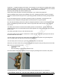
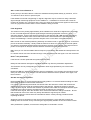
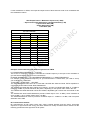
SATELLITE TV UPLINK INSTALLATION GUIDE Version 12/23/2010 UPLINK SITE PREPARATION GROUNDING THE SATELLITE UPLINK SYSTEM A mandatory step in keeping your system within safe operational conditions as well as with good performance is the grounding of your satellite components. A good grounding system is mandatory for your equipment survivability when operated in regions subject to lightening discharges! Another good reason is that in places where there is a lot of static build up, your radio electronics will fail intermittently. The Outdoor Equipment (ODU) at the antenna and the signal and electrical cables running from the Outdoor Equipment to the building should be properly grounded to avoid power surges that may damage the equipment or harm personnel. All antennas shall be grounded locally, with ground rods deployed as close as possible. All cable entries at the building shall be grounded at building entry. Cable entry ground shall be connected to building ground by AWG#4 copper wire. Cable entry ground shall be connected to antenna ground by AWG#4 copper wire. If you do not provide a separated and good ground wire between the antenna ground point and the building entrance ground, the only connection between the two sites will be your cables and equipment! If a lightning strikes in the area ( not necessarily to your antenna or building) there will be electrical voltages and currents in the ground . Any difference of voltages between the antenna ground and building ground may result in currents flowing between the two points. Electricity flows through the lowest resistance path. Guess which path it will prefer: the earth ground path or your cables and equipment? Identify available Earth ground points available at the site. Suitable grounding consists of a copper rod driven several feet into the ground or a grounding grid that is buried and covering a large surface area. Do not use floating grounds or grounds occupied by motors or generators. All high power, low frequency motors, equipment, and generators should have their own ground points. Run the antenna-building interconnect cable as straight as possible in a direct route between the two points. Put additional ground rods at each 15 feet. Put ground rods at each sharp corner or turn of wire course. The ODU ground must be connected to the Earth ground or to the antenna. The 000 AWG multiconductor copper wire is recommended to bond units together to the earth ground using the shortest (direct) route. The LNB is grounded to a lug on the antenna feed arm. The ground cable on the antenna is fastened to an Earth ground. This earth ground point should not be shared with the indoor units. You also need to ground the coax cable inside of the building with a special coax grounding block. This is normally done near the point of entry into the building. The red arrow points to where your grounding cable will connect to this block. While the coax cable needs to be grounded, it MUST NOT be part of the grounding circuit for the dish. Make sure you ground all the items: - Transmitter & LNB - Feed Arm - Non-Penetrating or king post or pedestal mount. All coaxial cables entering the building must go through a grounding block as shown in the picture Grounding blocks are normally found in the section of the hardware store for TV electronics. PLEASE MAKE SURE THAT THE UNIT AND CABLES ARE PROPERLY GROUNDED TO AVOID DAMAGES TO THE EQUIPMENT AND RISK TO PERSONEL ! – DAMAGES DUE TO POWER SURGES WILL VOID THE WARRANTY! OUTDOOR EQUIPMENT INSTALLATION Make sure the N-type connectors for the IF cables are securely fastened to the RF unit (both the Tx & Rx). Make sure the connectors are wrapped with mastic tape to prevent corrosion and water entry. The cables to the LNB should be fastened properly, tightened, and taped. The waveguide from the RF unit to the feed should be fastened properly with the proper gaskets and silicone. Inspect waveguides for any damages- even a tiny hole can reduce the performance drastically. Avoid overloading the antenna with heavy ODU that may cause dish distortion overtime. Whenever possible install ODUs in a manner that the fans and heatsink fins are facing down to minimize accumulation of dust, sand and debris. Keep fans running smoothly – clean or replace them in case of slowing down. Attempt to shake the antenna. If large movement patterns exist, then the fastening of the bolts was not performed properly. DEALING WITH LNBs Fit the LNB with a suitable feed horn and attach to the antenna ensuring correct LNB polarization. Connect a suitable 75 ohms low loss coaxial cable ( RG6 or RG11 )between the receiver RF input and the LNB. The connection to the LNB should be protected with self-amalgamating tape. The L Band receiving frequency is calculated as: LNB LO Frequency – C Band RX Frequency = L Band RX Frequency C Band LNBs typically cover the whole C Band frequency range and have a LO of 5150 MHz KU Band LNBs typically come in different frequency ranges as follows: 10.95 – 11.70 GHZ – LO 10.00 GHz - Some manufacturers refer to as C Type 11.20 – 11.70 GHZ - LO 10.25 GHz 11.70 - 12.20 GHZ – LO 10.75 GHz - Some manufacturers refer to as A Type or US Type 12.25 - 12.75 GHZ – LO 11.30 GHz - Some manufacturers refer to as B Type There are different types of LNBs in terms of frequency tuning stability: DRO (typically +/- 150KHz to +/- 500 KHz ) PLL Internal Reference ( +/- 2 ppm to +/- 10 pmm or +/- 28KHz to +/- 140KHz in KU Band ) PLL External Reference ( +/- 1 ppm or better or +/- 14KHz in KU Band ) For reception of TV and other larger carriers, a DRO LNB is usually sufficient. Narrower carriers may require a PLL LNB. ANTENNA ALIGNMENT / POINTING Clear Line of Sight The antenna must have a clear “line of sight” view of the satellite. This means that the pointing angle must be clear of tall buildings, trees and other high objects. If the view to the south is generally clear the antenna site will be suitable. However if there are obstructions to the south the actual pointing angles will have be checked to see if the site is suitable. Satellite Position Most communications satellites appear stationary in the sky from any location on the earth. This is because their speed is matched to the rotational speed of the earth taking into account the fact that their orbit is much greater than the earth’s circumference. These satellites are said to be in geostationary or geosynchronous orbits. Geostationary satellites can only have one orbit, which is 22,238 miles (35,786 kilometers) directly above the equator. The direction an antenna must point in order to receive the signal from a given satellite is determined by the antenna’s location north or south of the equator and the position on the equator over which the satellite is located. A satellite’s position is given in degrees of latitude and longitude in the same manner as a position on earth. Latitude and Longitude Latitude is measured in degrees north or south of the equator which is at 0 degrees latitude. The range is from 90 degrees north via 0 to 90 degrees south. Longitude is measured in degrees east or west of the Prime Meridian. The Prime Meridian is at 0 longitude and is an imaginary line running north/south on the earth’s surface from the north pole to the south pole and passing through the Greenwich Observatory in England. All other points in the world are either east or west of this line. There are 360 of longitude expressed as 0 to 180 east and 0 to 180 west. 180E is the same location as 180W and this position is the International Date Line. The latitude of a satellite is the same as that of the location on the equator directly below it. For the purpose of calculation, latitude and longitude are represented as decimals. The sign of the decimal is used to distinguish North (positive) and South (negative), and East (positive) and West (negative). Coordinates of a site can be easily obtained by a GPS or specialized web pages. Antenna Pointing Angles The Azimuth and Elevation angles along which an antenna must point to receive a particular satellites signal can be calculated. The information required for the calculation is the location, in latitude and longitude, of the antenna and the longitude of the satellite. Web Tools There are web pages that allow the easy and fast calculation for satellite antenna pointing angles, based on the site address or coordinates and the satellite orbital position. A very useful reference is www.dishpointer.com , which also provides calculation of obstacle height clearance for a given location and a satellite. You should obtain also some additional information about the satellite such as a list of TV channels that are on that satellite (the best known web page for that purpose is www.lyngsat.com ) . Most of the satellites have one or more beacon frequencies, which are clear-carriers (CW), nonmodulated signals at specific frequencies , that allow the users to identify whether they are pointed to the correct satellite in an easier manner. Get all Information Needed before Starting the Antenna Pointing Satellite Longitude Satellite Beacon Frequencies Pointing Angles Tx Frequency and Polarization RX Frequency and Polarization Eventual FTA (Free to Air) TV Channels on same satellite, band and polarization Obtain other frequencies of interest that may help to identify the satellite; try to obtain a satellite spectrum plot with the satellite operator. Some spectrum analyzers can store the spectrum plots of different satellites, a very helpful tool to identify the satellite. Mandatory Instruments for Antenna Pointing: Sighting compass to align the antenna in azimuth Inclinometer to set the elevation angle. Desirable Instruments L Band Spectrum Analyzer DVB-S FTA (Free to Air) Receiver Small TV Monitor Antenna Off-Set Most common type of small antennas in the market is the “off-set” antenna. In “off-set” antennas, the actual line of sight of the antenna is off set from the apparent visual line of sight. The dish is actually pointed to a higher elevation that it seems. Subtract any antenna offset from the required elevation angle when measuring. For example, if your satellite elevation angle is 23 degrees and the dish offset is 23 degrees, the antenna elevation angle should be 0 degree – the antenna should be appear to be horizontal but actually pointing to 23 degrees. This subtraction allows to place the inclinometer at the back structure part that is “parallel” to the reflector dish. Some antenna manufactures already provide a surface at the back structure that takes in account the off-set angle and in this case no offset is needed calculation is needed. Please refer to antenna manuals. Start with the Elevation First all make sure that the antenna support platform and pedestal tube are leveled! Adjust the antenna elevation as accurate as possible. Next is the Azimuth Align the antenna azimuth pointing with a magnetic compass; attention – antenna pointing angles are calculated for geographical azimuth angles; the use of magnetic compass needs to consider the magnetic declination. Typically, the support web pages provide already the magnetic azimuth to be used. If possible align the antenna azimuth by using a reference or placing the compass in front of the antenna and as far as possible ( 15 feet or more) – the farther you go more accurate will be the azimuth pointing. Am I on the Correct Satellite ?? At this point you should be able to confirm the satellite and transponder identity by a beacon, a FTA TV channel or other carrier or spectrum plot . If the satellite concerned is supporting TV signals, alignment may be carried out using a standard signal strength measuring equipment for the satellite TV. A satellite FTA receiver and a small TV monitor can be also very convenient as the user can check the channel names against a channel list such as Lyngsat and confirm that the correct satellite is being received. Final Alignment The antenna is now pointing approximately at the satellite but it needs to be aligned more accurately for use. Accurate alignment requires signal strength measuring equipment such as a L Band spectrum analyzer. Connect the spectrum analyzer to the antenna LNB. LNB requires a DC supply, ensure that this is enabled. Also ensure that a DC block is inserted before the spectrum analyzer input to avoid damage. Tune the spectrum analyzer to the correct down converted frequency. Make a mark on the azimuth positioning assembly and another mark, in line with the first, on the fixed part of the antenna assembly. Slowly rotate the antenna to about 10 either side of the mark (about one eighth of a quadrant) whilst watching the spectrum analyzer for the signal. If the signal is found peak it on the spectrum analyzer with the azimuth movement and lock the movement. Make sure you can see the satellite beacon frequency specified for the satellite and transponder to be used. In a similar manner move the elevation through a few degrees to peak the signal. Lock the movement. Now it’s the polarization If the feed is a circular polarized feed, please skip this step. Ideally the transmission waveguide should be installed only after the polarization adjustment. The feed horn can be pre-aligned to the polarization skew angle provided by one of the online calculators. Rotate the LNB horn assembly to peak the signal in polarization. You can also zero the signal on the other port of the feed, as it’s easier to see the null than determine that it’s peaked. Once again, lock the movement. Still did not find your satellite ? Repeat all the above to ensure that the signal is fully peaked. Lock all movements making sure that the locking off does not cause further movement. If no signal is found during the azimuth movement return the antenna to center and increase the elevation by an amount equal to the beam width of the antenna. Repeat the swings in azimuth. If there is still no signal, increase the elevation by another beam width and sweep the azimuth again. Continue in this manner until the elevation has been increase by 2 to 3 degrees. If there is still no signal, lower the elevation from nominal and make the swings in azimuth. Ensure that the azimuth moves are made very slowly otherwise the signal may be missed. If the signal cannot be found check the calculations and the coarse pointing procedure before repeating the above. Alignment can be rechecked once the receiver has acquired the correct signal by using Eb/No readings from the receiver and by monitoring the signal quality indicator on the front of the receiver. After polarization is peaked, check that the waveguide is not twisted in excess. SETTING THE MODULATOR AND THE ENCODER Digital Video and Encoders The MPEG2 or MPEG4 encoders takes video and audio inputs in the digital format SDI or as analog signals such as CVBS video, XLR balanced audio, Component Video or unbalanced audio. SDI inputs can be in the format SDI video + Analog Audio or have both video and audio in the SDI digital stream – the so called embedded audio SDI. Typically the SDI signal has a data rate of 270Mbps. MPEG2 and MPEG4 encoders are used to compress the original video and audio signals in order to save satellite bandwidth which is very expensive as well as to provide better performance by digitizing the signals. MPEG4 is a newer compression standard and can provide a video quality “equal” to MEPG2 with 50% of the data rate ( and of the bandwidth ) – video quality is a subjective factor and this comment is based on practical experience. A digital SDI signal of 270Mbps can be compressed to 2.7 Mbps with good video quality, a reduction of 100 x in bandwidth requirements! Typically the output of the encoder is an ASI data stream with a data rate corresponding to the compression used, which is fed to the modulator input. Data Rate Vs. Symbol Rate In order to configure all the equipment in an uplink station it is important to understand the differences between two similar, related but different terms: Data Rate and Symbol Rate. As a practical consideration, Data Rate is related to the output of the encoder and to the input signal to the modulator. The encoder will output a data stream with a data rate that is the total of the video data rate plus the audio date rates plus some overhead. The modulator will assemble an output transport stream which should be able to carry the input load, comparable to a train that need to have enough wagons to transport the load. The modulator data rate should be equal or higher than the encoder data rate (attention – some modulators require that both data rates should be the same ! ) If the modulator data rate is lower than the encoder data rate, data will be lost and you will get buffer alarms. Attention: Data rate is measured in bits per second ( bps ) or multiples – Kbps , Mbps The modulator will take the data stream, measured in Mbps, and carried in short distance media such as cable and process it into a format that can be transported by long distance media such as satellite or fiber optics cable , where the data stream “rides” on a electromagnetic wave of much higher frequencies. This process is called modulation. The modulator also adds forward error correction schemes - it includes additional bits to allow to receiving end to correct eventual transmission errors , based on the additional bits with check sums and other correction codes. For example, a FEC (forward error correction) scheme of ½ means that 50% of the bits in the final data stream are check bits added to the original user data rate in order to allow identification and correction of eventual errors . The modulation scheme indicates how the data stream bits are represented in the higher frequency carrier wave, such as BPSK, QPSK, 8PSK, 16-QAM, 32-QAM. Symbol Rate is the transmitted data rate, and is dependent on Data Rate, FEC Code Rate, and Modulation scheme. To calculate the Symbol Rate, the formula is as follows: 1 Symbol Rate = Data rate x /Code Rate Modulation Where Modulation = 1 for BPSK; 2 for QPSK; 3 for 8PSK, and 4 for 16QAM Symbol rate is measured in symbols per second or baud TV channels listings typically have the transponder frequency, the symbol rate and the FEC. However, the commercial satellite TV receivers only need the frequency and the symbol rate and they will check the FEC and open the channel if possible. As you can see, symbol rate and data rate are not the same thing. This is an important distinction because modulators quite often are configured based on symbol rate, showing Msps or Mbaud at the display and that cannot be confused with Mbps or data rate! Symbol Rate is more directly related to the satellite bandwidth occupied by a TV channel on the satellite transponder. However bandwidth is measured in KHz or MHz. In an ideal scenario, 1 Msps would occupy 1 MHz of the bandwidth. However the spectrum analyzer plot of the output of a real modulator will show that a 1 Msps carrier will occupy more than 1MHz of bandwidth. The ratio between the actual bandwidth and the theoretical bandwidth (mega-symbol rate value expressed in MHz) is called “roll-off ratio” Modulators are designed to provide 1.2, 1.25, 1.35 roll-off ratios. Some are fixed, some are adjustable. The final bandwidth to be paid to the satellite operator will depend on a band guard factor, set by the satellite operator to make sure that you don’t overlap on someone’s else carrier, and typically the band guard factor is higher than the roll-off . 35% is common practice. Attention: Some modulators give an indication of symbol rate and MHz. The MHz readings at the modulator panel do not consider the roll-off and band guard ratios. SETTING L BAND (IF) AND RF FREQUENCIES The output of modulators is provided in a lower RF frequency usually referred to as IF ( Intermediate), at lower power levels and that output has to be fed to the transmission chain that will convert the signal to the satellite frequencies ( KU or C Band ) and also do the necessary amplifications . In the past the modulators used IF frequencies of 70MHz or 140MHz. The output could be set within a range of +/- 36 MHz. One satellite typically has several transponders of 36 MHz or 72 MHz distributed in the overall range of the frequency band, such as 500 MHz for normal KU Band (14,000 – 14,500 MHZ ) The use of the “IF” up-converters ( such as in transceivers ) requires the up-converter to be set at a transponder center frequency corresponding to the 70MHz or 140MHz center frequency and then the modulator frequency is varied around the 70MHz or 140MHz to get to the desired transponder frequencies. With the advent of the Block Up-Converters (BUC), which take L Band input signals from modulators, typically from 950MHz to 1450MHz ( whole 500MHz range ) and convert to either KU Band or C Band, the calculation of uplink frequencies can be easily done , based on the BUC Local Oscillator frequency and the modulator output. BUCs have LO frequencies in accordance to the frequency band to be covered such as: Standard C Band 5.85 – 6.425 GHz - LO = 4900MHz ( normal spectrum ) Standard C Band 5.85 – 6.425 GHz - LO = 7375MHz ( inverted spectrum) Standard KU Band 14.0 – 14.5 GHz – LO = 13.05GHz Extended KU Band 13.75 – 14.5 GHz – LO= 12.8 GHz Use the following formula to determine the modulator IF frequency based from upon the transmit frequency: BUC TX frequency - BUC LO = Modulator IF carrier frequency. Example for the desired TX frequency of 14.250 GHz: 14.250 - 13.050 = 1200 MHz. Transmission Power Level Budget A typical power level budget includes the following elements: - Modulator with L Band Output 10MHz+24VDC Insertion Unit with Variable ( or Fixed ) Attenuation L Band Cable Run L Band to KU Band or C Band Up-Converter Heliax or Waveguide Interconnect HPA – High Power Amplifier HPA Output Power = + Modulator Ouput Level ( dBm) – Upconverter Input Attenuation ( variable attenuator) ( dB) + Upconverter Gain (dB) –Cable Attenuation (dB) + HPA Gain (dB) Output power levels of modulators and other signal generating devices are typically presented in dBm. Table below presents conversion between dBm and Watts. dBm Watts DBm Watts dBm Watts 0 1.0 Mw 16 40 mW 32 1.6 W 1 1.3 mW 17 50 mW 33 2.0 W 2 1.6 mW 18 63 mW 34 2.5 W 3 2.0 mW 19 79 mW 35 3.2 W 4 2.5 mW 20 100 mW 36 4.0 W 5 3.2 mW 21 126 mW 37 5.0 W 6 4 mW 22 158 mW 38 6.3 W 7 5 mW 23 200 mW 39 8.0 W 8 6 mW 24 250 mW 40 10 W 9 8 mW 25 316 mW 41 13 W 10 10 mW 26 398 mW 42 16 W 11 13 mW 27 500 mW 43 20 W 12 16 mW 28 630 mW 44 25 W 13 20 mW 29 800 mW 45 32 W 14 25 mW 30 1.0 W 46 40 W 15 32 mW 31 1.3 W 47 50 W Typically, inputs of converters and amplifiers are presented in dBm. Typically outputs of Amplifiers are presented in Watts or dBW . 100 Watts = +50 dBm = +20 dBW 1 Watt = +30 dBm = 0dBW Equipment have either Gain or Losses. Gain or Losses are expressed in dB. Rule of thumb: each 3 dB gain doubles the power level Example +30dBm ( 1 W ) + 3 dB = +33dBm ( 2W ) Important: HPAs have different maximum input power level specification and feed a power level higher than the specified maximum may damage the equipment. Even if the equipment is not damaged, it will saturate and will operate out of the linear range with signal distortions and spurious outputs. Modulators have outputs typically ranging for – 35 dBm to +5 dBm Indoor up converters have relatively lower outputs, also in the range above -35dBm to +5 dBm. Outdoor Up converters ( BUC ) are typically 30 dBm to 33 dBm . In general they need inputs in the 20 dBm range . However 0dBm Outdoor Up-converters are very common also. Typically, TWTAs ( tube amplifiers ) have high gain and require low input power ( such as – 10 dBm to + 10 dBm. Most were designed to be used with indoor up-converters Several units are designated as “boosters” (BST) which typically describes an unit with low gain , which requires a higher input : +30 dBM to + 33dBm and they are used with higher power BUC drivers , such as +30 dBm Attention: all values above are given as examples only, to get the user familiarized with the power ranges and terminology. Please refer to specific data sheets and manuals for your specific equipment. Cable Attenuations and Length Install cables in the most direct route possible. Cables should be tied, avoiding it to hang loose and get elongated over time and lose performance. Leave enough cable slack to move the antenna. Connect UC-250L to BUC (IFL) using low-loss 50-Ohm cable with type N (male) connectors at each end. The cable loss must not exceed 12.5 dB at 2000 MHz. Cable centre conductor DC resistance (end to end) must not exceed 0.5 Ω. For cable runs up to 100 meters, use LMR-400 or equivalent. The ideal situation is to have the modulator output power of -25 dBm If cable with a more typical loss of 12 dB per 100 feet is used, the maximum cable run is approximately 100 feet. Other cables can be substituted for the LMR-400 Times Microwave Systems cable, such as the CommScope 3227 cable, which has an attenuation of 6.05 dB @ 1800 MHz, which will increase the distance from the modem to the BUC by up to 200 feet. Slightly longer cable lengths are possible with BUCs of higher gain, though the slope delta worsens with rising frequency. Through the use of special slope equalizers and amplifiers, the distance between the modem and the BUC can be extended. It is important to note that a +24/+48 VDC offset and a 10MHz reference signal may be present at the modulator output. The DC voltage may supply up to 4 Amperes and will damage any DC coupled device (such as an attenuator) connected to the modulator output. Also, a typical attenuator on the modulator output would reduce the level of 10 MHz reference signal available to the BUC. Also available are amplitude/slope equalizers that compensate for losses and “tilt” caused by the cable and other devices between the modem and the BUC, such as power combiners. Some are rack-mounted units, which include self-contained power supplies, and others are in-line modules that utilize the DC power from the modem. For the receive cables use RG-6 for short runs, RG-11 for longer runs and add in-line amplifiers as needed. Attention to LNB PLL with External Reference that need 10MHz reference – not all in-line amplifiers will carry 10MHz . RECOMMENDED PROCEDURE FOR OPERATION START UP The following procedure is recommended for safe operation of the TWTA. 1. Set the modulator at a minimum lowest output level ( = 95 dBu with UC-250L) 2. Set the variable attenuator at the front panel to 10 dB 3. These settings should provide with an output of approximately (-) 22 dBm 4. Start the operations with the TWTA, varying the gain of the HPA and check whether you can obtain the desired RF output level 5. If you need to increase the input level , you can start by setting front panel attenuation to 0 dB 6. If that is not sufficient, you can increase the power level output at the modulator The settings above consider the cable attenuation between the upconverter and the TWTA provided by the low loss cables provided with the unit . Adjustments in the power settings can be made to take into account longer cables. If other modulators or HPAs, the output and input levels of those devices need to be considered and the calculations redone. HPA Output Power = Modulator Ouput Level ( dBm) – Upconverter Input Attenuation ( variable attenuator) ( dB) + Upconverter Gain (dB) –Cable Attenuation (dB) + HPA Gain (dB) UC 250L MODEM Modem Settings 95 dBu 96 dBu 97 dBu 98 dBu 99 dBu 100 dBu 101 dBu 102 dBu 103 dBu 104 dBu 105 dBu 106 dBu 107 dBu 108 dBu 109 dBu 110 dBu Modem Output Power -10 dBm -9 dBm -8 dBm -7 dBm -6 dBm -5 dBm -4 dBm -3 DBm -2 DBm -1 DBm 0 DBm 1 DBm 2 DBm 3 DBm 4 DBm 5 DBm Example of 400 watts Extended KU Band System with TWTA LO CONVERSION FREQUENCY – 12.8 GHZ This is the LO Frequency needed to calculate the L Band Frequency to be input in the modulator to give the final KU Band required for the transmission. KU BAND FREQUENCY = LO CONVERSION FREQUENCY + L BAND FREQUENCY For example, if the authorized frequency for your transmission is 13.800 GHZ, you need to set up your modulator to 1.000 GHZ 13.800 GHZ = 12.800 GHZ + 1.000 GHZ The UPCONVERTER was tuned to be used with UPCOM 400 watts KU Band TWTA Amplifiers in conjunction to UPCOM UC-250L DVB-S Modulators. The UPCOM 400 watts KU Band TWTA HPA requires an input in extended KU Band of -10 dBm to maximum 10dBm to provide maximum RF power, depending on the specific TWT used in the unit. The UPCOM 400 watts KU Band TWTA has variable, adjustable gain. Please see the manual for the unit. The UPCOM UC-250L DVB-S Modulators provide L Band output from -12 dBm ( when modulator is set to 95 dBu ) up to +3 dBm (when set to 110 dBu ). The UPCONVERTER is tuned to provide a KU Band output of -10dBm to +2 dBm, with front panel attenuator set to 0dB RF Transmission Hazards RF transmissions at high power levels may cause eyesight damage and skin burns. Prolonged exposure to high levels of RF energy has been linked to a variety of health issues. Please use the following precautions with high levels of RF power. Always terminate the RF input and output connector prior to applying prime AC input power. Never look directly into the RF output waveguide. Maintain a suitable distance from the source of the transmission such that the power density is below recommended guidelines in ANSI/IEEE C95.1. The power density specified in ANSI/IEEE C95.1-1992 is 10 mW/cm². These requirements adhere to OSHA Standard 1910.97. When a safe distance is not practical, RF shielding should be used to achieve the recommended power density levels. Operating a RF transmitter with open waveguide flanges without termination to an antenna or a dummy load is hazardous and will void the warranty. S/N TO Eb/No CONVERSION Eb/N0 is defined as the ratio of Energy per Bit to Spectral Noise Density in a 1 Hz bandwidth. It is used in digital communications to define the signal strength required at the input of the demodulator to provide a desired Bit Error Ratio (BER). Eb/No is independent of the system data rate and symbol rate. Eb/No is difficult to measure with standard test equipment, such as Spectrum Analyzers. The typical Spectrum Analyzer displays a ratio of Signal plus Noise/Noise, or (S + N)/N. A simple but quick method of determining Eb/No is obtained by measuring the (S + N)/N value using an accurate Spectrum Analyzer. The analyzer needs to be looking at the same signal that the demodulator will see. A two-way power divider in the receive path with one output connected to the Spectrum Analyzer and the other to the demod input is acceptable. The common input would be from the satellite feed. Follow the steps below to obtain a reasonable measurement of (S + N)/N, which then can be translated to Eb/No values by using the following charts. Set the Resolution Bandwidth to less than 20% of the transmitted symbol rate. Set the Video Resolution to reduce the noise variation. Video averaging is also acceptable, if the analyzer has that feature. Start at 10 dB per vertical division and scale down to 2 dB (if possible) to obtain the noise floor / carrier within the same display. This will allow the measurement to be more accurate. Using the Spectrum Analyzer marker, place the marker over the center part of the wanted carrier. If the analyzer includes a delta measurement capability, then use the delta marker placed over a blank area of the noise (no carriers present), and read the difference between the carrier level and the noise level. This value is the (S + N)/N. If the spectrum analyzer does not have a delta marker function, then record the carrier signal level, then record the noise level, and subtract the two. This value will constitute the (S + N)/N reading.