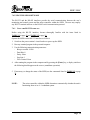
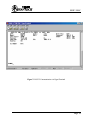
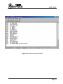
1
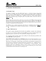
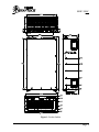
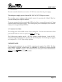
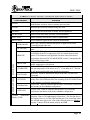
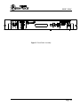
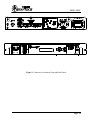
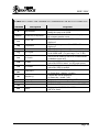
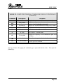
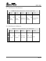
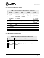
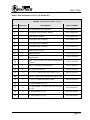
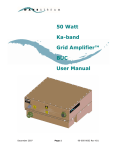
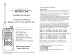
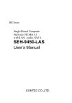
INSTALLATION AND OPERATION MANUAL
200 WATT L-BAND TO C-BAND RACK-MOUNT
SOLID STATE TRANSMITTER
SSPB-3000C
PM 150-50N415-6G0, Rev. 1
SSBP-3000C
WARRANTY
This ADVANTECH Advanced Microwave Technologies Inc. product is warranted against defects
in material and workmanship for a period of 2 years from date of shipment. During the warranty
period, ADVANTECH Advanced Microwave Technologies Inc. will, at its option, either repair or
replace the product, which proves to be defective.
To return a product for warranty or repair service, first request a Return Material Authorisation
(RMA) number by contacting ADVANTECH at:
Phone:
(514) 420-0045
Website: www.AdvantechAMT.com
or
or
Fax: (514) 420-0073
e-mail: [email protected]
The product should be shipped to the following address, in the original shipping container (box),
with the prepaid shipping charges.
ADVANTECH Advanced Microwave Technologies Inc,
657 Orly Avenue
Dorval, Quebec
H9P 1G1
CANADA
Please indicate the RMA number on all shipping documentation.
Units shipped without a prior issued RMA, or not shipped in the original container, may be
rejected and returned at sender’s expense.
LIMITATIONS OF WARRANTY
ADVANTECH Advanced Microwave Technologies Inc. warrants this product to be free of
defects in materials and workmanship.
The foregoing warranty shall not apply to defects resulting from improper handling or abuse by the
purchaser, unauthorised modification, operating outside of the product’s environmental
specifications, improper installation or maintenance.
ADVANTECH Advanced Microwave Technologies Inc. shall not be liable for any direct,
indirect, special, incidental or consequential damages.
Page 1
SSBP-3000C
CONTENTS
1.
SAFETY.................................................................................................................................................................... 6
2.
GENERAL INFORMATION ............................................................................................................................... 8
2.1
2.2
3.
INTRODUCTION........................................................................................................................................................8
ABOUT THIS MANUAL.............................................................................................................................................8
MAJOR COMPONENTS AND THEIR FUNCTION..................................................................................... 10
3.1 L-BAND TO C-BAND UP-CONVERTER MODULE............................................................................................ 10
3.2 P OWER AMPLIFIER MODULE ................................................................................................................................ 10
3.3 WAVEGUIDE ARM ASSEMBLY............................................................................................................................... 11
3.4 10 MHZ OSCILLATOR ......................................................................................................................................... 11
3.5 MAIN CONTROLLER BOARD ................................................................................................................................. 11
3.5.1
Fault Detection and Indication ............................................................................................................ 12
3.5.2
MUTE Control ........................................................................................................................................ 12
3.6 P OWER SUPPLY SYSTEM....................................................................................................................................... 12
3.7 COOLING SYSTEM................................................................................................................................................. 13
3.8 FRONT P ANEL ...................................................................................................................................................... 13
3.9 ELECTRICAL SPECIFICATIONS ............................................................................................................................... 17
4.
INTERFACES....................................................................................................................................................... 18
4.1
4.2
4.3
4.4
4.5
5.
DISCRETE INTERFACE ........................................................................................................................................... 18
RS-232 INTERFACE ............................................................................................................................................. 19
RS-485 INTERFACE ............................................................................................................................................. 20
RF OUTPUT MONITOR INTERFACE ....................................................................................................................... 20
REDUNDANT INTERFACE ...................................................................................................................................... 20
UNPACKING AND INSTALLATION............................................................................................................... 22
5.1 INITIAL INSPECTION.............................................................................................................................................. 22
5.2 UNPACKING ......................................................................................................................................................... 22
5.3 INSTALLATION ..................................................................................................................................................... 22
5.3.1
Environmental and Adequate Ventilation Considerations.............................................................. 25
5.3.2
Mechanical Installation ........................................................................................................................ 25
5.3.3
Electrical Connections .......................................................................................................................... 26
5.3.4
RF Connections ...................................................................................................................................... 28
6.
PRE-POWER AND SYSTEM CHECKOUT.................................................................................................... 29
6.1
6.2
7.
P RE-POWER P ROCEDURES .................................................................................................................................... 29
OPERATIONAL SETTINGS VERIFICATION ............................................................................................................... 29
OPERATION......................................................................................................................................................... 30
7.1 INTRODUCTION..................................................................................................................................................... 30
7.2 SAFETY CONSIDERATIONS.................................................................................................................................... 30
7.3 BASIC OPERATING P ROCEDURE............................................................................................................................ 30
7.4 FRONT P ANEL OPERATION ................................................................................................................................... 31
7.5 DOWNLOADING THE SUPPLIED SOFTWARE ........................................................................................................... 32
7.6 USING THE SSPB SOFTWARE .............................................................................................................................. 34
7.6.1
Using the RS-232 Interface................................................................................................................... 34
8.
MAINTENANCE .................................................................................................................................................. 40
Page 2
SSBP-3000C
8.1
8.2
8.3
9.
P REVENTIVE MAINTENANCE................................................................................................................................. 40
MECHANICAL P REVENTIVE MAINTENANCE .......................................................................................................... 40
COOLING FAN CHECK........................................................................................................................................... 40
RS-485 SERIAL COMMUNICATION PROTOCOL .................................................................................... 41
9.1 FRAME STRUCTURE .............................................................................................................................................. 41
9.2 COMMANDS......................................................................................................................................................... 42
9.3 RESPONSE TO COMMANDS FROM SLA VE TO MASTER ........................................................................................... 43
9.3.1
Condition Status Response................................................................................................................... 43
9.3.2
Read Identification Response............................................................................................................... 43
9.3.3
Read Frequency Range Response........................................................................................................ 44
9.3.4
Read Frequency Set Response ............................................................................................................. 44
9.3.5
Unit Status and Position Response ..................................................................................................... 45
9.3.6
Read Frequency Shift Response........................................................................................................... 45
10.
PACKING LIST.................................................................................................................................................... 46
11.
APPENDIX A: SAFETY AND EMC COMPLIANCE.................................................................................... 48
Page 3
SSBP-3000C
FIGURES
FIGURE 1: PRODUCT OUTLINE.........................................................................................................9
FIGURE 2: SSPB BLOCK DIAGRAM ..............................................................................................14
FIGURE 3: FRONT PANEL ASSEMBLY ............................................................................................16
FIGURE 4: 1:1 REDUNDANT SYSTEM .............................................................................................21
FIGURE 5: CONNECTORS LOCATION ON FRONT AND BACK PANELS .............................................24
FIGURE 6: FRONT PANEL SEQUENCE ............................................................................................33
FIGURE 7: RS-232 COMMUNICATION VIA HYPERTERMINAL.........................................................35
FIGURE 8: HELP FUNCTION IN HYPERTERMINAL...........................................................................37
FIGURE 9: REDUNDANT SYSTEM (REAR VIEW) ..............................................................................49
FIGURE 10: REDUNDANT SYSTEM (LATERAL RIGHT VIEW).............................................................50
FIGURE 11: REDUNDANT SYSTEM (LATERAL LEFT VIEW)...............................................................51
FIGURE 12: REDUNDANT SYSTEM (TOP VIEW) ..............................................................................52
FIGURE 13: RS-232 COMMUNICATION VIA HYPERTERMINAL FOR REDUNDANT SYSTEM..............53
FIGURE 14: PROPOSED GRAPHIC USER INTERFACE FOR A REDUNDANT SYSTEM BASED ON RS-485
PACKET PROTOCOL ...............................................................................................................54
Page 4
SSBP-3000C
TABLES
TABLE 1: FRONT PANEL CONTROLS AND INDICATIONS ................................................15
TABLE 2: ELECTRICAL SPECIFICATIONS............................................................................17
TABLE 3: DISCRETE INTERFACE (J3) RELAY – PIN ASSIGNMENTS...............................19
TABLE 4: RS-232 SERIAL INTERFACE (J2) RS232 – PIN ASSIGNMENTS.........................19
TABLE 5: RS-485 SERIAL INTERFACE (J12) RS485 – PIN ASSIGNMENTS.......................20
TABLE 6: CONNECTORS .........................................................................................................23
TABLE 7: ENVIRONMENTAL CONDITIONS .........................................................................25
TABLE 8: SERIAL INTERFACE CONNECTION INFORMATION RS-232............................27
TABLE 9: POWER REQUIREMENTS.......................................................................................28
TABLE 10: AC LINE (J5) CONNECTOR – PIN ASSIGNMENTS............................................28
TABLE 11: RS-232 MENU ITEM DEFINITION........................................................................36
TABLE 12: COMPUTER TERMINAL COMMANDS FOR RS-232 INTERFACE ...................38
TABLE 13: COMMAND FRAME STRUCTURE.......................................................................42
TABLE 14: RESPONSE FRAME STRUCTURE........................................................................43
TABLE 15: READ IDENTIFICATION RESPONSE ..................................................................43
TABLE 16: READ FREQUENCY RANGE RESPONSE ...........................................................44
TABLE 17: READ FREQUENCY SET RESPONSE..................................................................44
TABLE 18: UNIT STATUS AND POSITION RESPONSE........................................................45
TABLE 19: READ FREQUENCY SHIFT RESPONSE..............................................................45
TABLE 20: PACKING LIST.......................................................................................................46
TABLE 21: REDUNDANCY KIT...............................................................................................47
Page 5
SSBP-3000C
1. SAFETY
To prevent the risk of injury to personnel or loss related to equipment malfunction, ADVANTECH
uses the following symbols throughout this document to indicate safety-related information.
WARNING: This indicates a hazardous procedure that may result in serious injury or death
ifCAUTION:
not performed properly.
This indicates a hazardous procedure that may result in light-to-severe
injury or loss related to equipment malfunction, if proper precautions are not taken.
For your own safety, read the following carefully BEFORE operating this equipment!
---------------------------------------------------- WARNING --------------------------------------------When supplying power to this equipment, verify that the power cable (not supplied) has the correct
pin assignment as given by TABLE 10 at page 28. Connect the cable to a properly grounded 3-pin
power outlet. Also connect a ground strap between the station’s ground bus and the ground screw
on the vertical rack. If power is supplied without grounding the equipment, there is a risk of
receiving a severe or fatal electric shock. In the context of this document any voltage that is lethal
is viewed as ‘High Voltage’. The prime power potential of 180-264 VAC applied to the
equipment is known to cause injury or death.
--------------------------------------------------- WARNING ---------------------------------------------The operator cannot repair this equipment. DO NOT attempt to remove the transmitter
cover or disassemble the internal components. Only qualified service technicians should
service the transmitter. There are high-voltage parts within the unit, which present a risk of severe
injury to the untrained personnel. In addition, there is a risk of damaging the delicate components.
--------------------------------------------------- WARNING ---------------------------------------------ALWAYS TERMINATE THE RF OUTPUT WAVEGUIDE PORT OF THE
TRANSMITTER WITH A RF LOAD CAPABLE OF DISSIPATING FULL CW RF
POWER. ALSO, TERMINATE THE IF INPUT CONNECTOR TO AVOID THE
POSSIBILITY OF THE UNIT BEING DRIVEN BY STRAY LEAKAGE SIGNALS.
Page 6
SSBP-3000C
Incorporate the terminations prior to applying prime power to the transmitter. This procedure
prevents self-oscillation and irradiation from and into the local environment. If the IF input of the
transmitter is not connected to a RF source, the unit may go into a self-induced mode and generate
high levels of RF energy. Destruction caused by an excessive load voltage standing wave ratio
(VSWR) will void the warranty.
--------------------------------------------------- WARNING ---------------------------------------------DO NOT LOOK INTO THE RF OUTPUT PORT OF THE POWERED TRANSMITTER!
Handle the unit with extreme care. Although the levels of microwave radiation do not induce
immediate physical discomfort in most individuals, the levels may be sufficiently high to induce
long-term effects. The eyes are the most vulnerable parts of the body.
The maximum permissible levels of RF exposure are quite low compared to the power levels
emitted by the transmitters built by Advantech (e.g. less than 10 mW versus 10 to 500 W for the
units). The maximum permissible levels are currently being studied by a number of organisations.
In the past, the U.S. Safety Code established a dosage rate of 10 mW/cm2. Currently, consideration
is being given to reduce the permissible level to 1 mW/cm2 in the United States, as has been the
case for several European countries.
---------------------------------------------------- CAUTION ---------------------------------------------THE TRANSMITTER UNIT IS HEAVY! TWO INDIVIDUALS OR A LIFTING DEVICE
MUST BE USED TO LIFT AND MOVE THE UNIT. There is a risk of back injury, if carried
or lifted by a single person.
In addition to this Section, included by reference are the following pertinent sections of the
International Standard IEC-215, ‘Safety requirements for radio transmitting equipment’:
Appendix D, ‘GUIDANCE ON ASSESSING THE COMPETENCE OF PERSONNEL FOR
DESIGNATION AS SKILLED’ and also Sub-clause 3.1 of the Standard.
Appendix E, ‘GUIDANCE ON SAFETY PRECAUTIONS TO BE OBSERVED BY PERSONNEL
WORKING ON RADIO TRANSMITTING EQUIPMENT’ and also Sub-clauses 3.2, 3.7 and 22.1
of the Standard.
Page 7
SSBP-3000C
2. GENERAL INFORMATION
2.1 INTRODUCTION
The ARMU-LC200-BRN , part of the SSPB-3000C family, is a 200-Watt L-Band to C-Band Solid
State Up-Converter (SSPB) designed for satellite up-link communication systems. The SSPB is an
indoor unit conceived for mounting into a standard 19-inch rack. The RF output should be
connected to an antenna using a waveguide system. The product outline of the unit is shown in
Figure 1 at page 9.
Built-in monitor and control features indicate the current status of the SSPB unit and provide fault
detection and protection when operating outside normal operating conditions. The SSPB also
allows the user access to the monitor and control functions by using the Relay (Discrete) Interface,
or the RS-232 and the RS-485 Serial Interfaces.
The SSPB unit can be combined with another unit to form a 1:1 redundant system (see Figure 4 at
page 21). A redundancy kit is available as an option to build a 1:1 redundant system.
2.2 ABOUT THIS MANUAL
This manual contains information that describes the installation, operation and maintenance
procedures for the 200-Watt C-Band rack-mount SSPB Up-Converter. Warnings appear at the
appropriate points to caution all users of the potential RF and high-voltage hazards.
For a safe and versatile operation, please read carefully all of the information provided by this
manual BEFORE using this equipment!
ADVANTECH Advanced Microwave Technologies, Inc. has prepared this manual for use as a
guide for the proper installation, operation and maintenance of the ADVANTECH Solid State
High Power Up-Converters. The drawings, specifications and information contained herein
are the property of ADVANTECH Advanced Microwave Technologies, Inc. Unauthorised use or
disclosure of these drawings, specifications and information is strictly prohibited. These
documents shall not be reproduced, copied or used in whole or in part as the basis for
manufacturing or sale of the equipment or software programs without the prior written consent
of ADVANTECH Advanced Microwave Technologies, Inc.
Page 8
SSBP-3000C
Figure 1: Product Outline
Page 9
SSBP-3000C
3. MAJOR COMPONENTS AND THEIR FUNCTION
This Section describes the major components and their functions within the SSPB unit. The SSPB
incorporates an L-Band to C-Band Up-Converter module, a Power Amplifier module, a
Waveguide Arm assembly, a 10 MHz oscillator, a Main Controller board, a Power supply
subsystem, a Current Sensor, a Cooling system and a Front Panel assembly. The remote
monitoring and control of all major parameters is possible via the RS-232 and RS-485 interfaces.
3.1 L-BAND TO C-BAND UP-CONVERTER MODULE
The L/C-Band Up-Converter Module converts and amplifies the incoming L-Band signals into
the desired C-Band carrier signals.
The module has an internal synthesiser, which is fixed at 4900 MHz.
To control the output power level of the converter, an attenuator is used to provide the system gain
control.
The Up-Converter module has RS-485 communication to the Main Controller board. An additional
discrete signal is available at this module: the Alarm Up-Converter (output).
3.2 POWER AMPLIFIER MODULE
The Power Amplifier Module amplifies the RF C-Band signals from the L/C-Band Up-Converter
module over the frequency range of 5.850 GHz to 6.425 GHz. The power amplifier has a 60 dB
typical gain.
For monitoring, the power amplifier has an RS-485 interface, which connects to the main
controller board. Two additional discrete signals are available at this module: the Alarm PA
(output) and the Mute PA (input) for muting the Power Amplifier.
A temperature sensor is installed at the hot spot of the module to monitor the temperature. When
the hot spot temperature exceeds +85 ºC, a shutdown command is issued by the controller of the
module, in order to prevent the damage of the RF devices due to overheating.
The controller of the Power Amplifier also has the following functions:
1. Provides and removes the DC voltages to the GaAs FET devices within the module.
2. Sends a FAULT signal to the main controller board when detecting a fault.
The Power Amplifier will be in Mute mode if:
1. The Main Controller board sends a MUTE command to the PA module.
2. The hotspot temperature exceeds 85°C,
Page 10
SSBP-3000C
3. Any of the GaAs FET devices fails (current is out of range)
3.3 WAVEGUIDE ARM ASSEMBLY
The Waveguide Arm Assembly contains a forward power detector, a reverse power detector, a
RF isolator, an output power coupler, and a waveguide band-pass filter.
The forward power detector and the reverse power detector monitor the RF output power and the
reflected power level and sends these detected signals to a Digital Power Monitor module, that
converts these analogue signals into digital ones. The digital signals are sent to the Main
Controller board via an RS-485 serial interface.
The RF isolator provides VSWR protection at the SSPB RF output port. The VSWR at the isolator
output is 1.25:1, minimum. The termination load of the isolator is capable of absorbing full
reflective power. A CPR-137 grooved waveguide flange is the output of the unit.
3.4 10 MHZ OSCILLATOR
This circuit is used to generate a 10 MHz reference signal with a high stability of 3 x 10⁻⁸ typical,
which is required by the Up-Converter module. The 10 MHz signal is provided to the UpConverter module via a coaxial cable.
3.5 MAIN CONTROLLER BOARD
The Main Controller Board contains a microprocessor controller that performs all of monitoring
and the control, input/output communication and the decision-making. The main controller board
provides:
1. Fault detection and indication from each part of the unit
2. Mute control and indication
3. Forward RF power detection and indication
4. Reflected power detection and indication
5. Power On indication (front panel LED)
6. Redundancy control (1:1 redundant system)
7. Frequency control
8. Unit gain control (attenuation setting).
9. Discrete Interface, RS-232 and RS-485 Serial Interfaces
Page 11
SSBP-3000C
3.5.1
FAULT DETECTION AND INDICATION
The unit will automatically go into a shutdown mode and send a message to all of the external
interfaces when any one of the following occurs:
1. The local oscillator within an up-converter module is out of lock.
2. The hotspot temperature exceeds 85°C.
3. Any of the GaAs FET devices fails.
The SSPB continually monitors the internal temperature and the current consumption. It also has
an automatic shutdown feature to prevent operation at excessive temperatures. The unit will
automatically restart when the hotspot temperature falls below 65°C.
A thermal alarm may result from any one of the following conditions:
1. High ambient temperature (SSPB is designed to operate between 0°C and + 50 °C ambient).
2. Blockage at the air intake or exhaust vents.
3.5.2
MUTE CONTROL
The user can disable the RF output power remotely by:
1. Leaving unconnected pins 1 and 5 of the RELAY Interface connector.
2. Sending a mute command in terminal mode through the RS-232 interface.
3. Sending a mute command in packet mode through the RS-485 interface.
This feature is useful if the user wishes to perform a maintenance check or to check out the
transmission system.
3.6 POWER SUPPLY SYSTEM
The Power Supply System has one input: 180-264 VAC. The power supply provides a +12 VDC
high current output to the following modules via relay K1 and the ON/OFF switch (see Figure 2 at
page 14):
1. Power amplifier module,
2. L/C-Band up-converter module,
3. Secondary power supply,
4. Varifan power supply,
5. 10 MHz oscillator,
6. Redundancy waveguide switch, (if working in the redundancy mode) and
Page 12
SSBP-3000C
7. Current sensor.
The main controller board also receives the +12 VDC low current from the power supply.
The main power supply operates from an 180 - 264 VAC, 47-63 Hz power source.
The secondary power supply provides multiple outputs for operating the L-Band/C-Band upconverter and the power amplifier modules.
To prevent unwanted noise from entering the SSPB, a line filter is connected between the AC input
connector and the main power supply. The overall typical power consumption, at the rated RF
output power, is approximately 400 Watts.
3.7 COOLING SYSTEM
The cooling system for the SSPB consists of four cooling fans. Two fans are mounted at the front
panel and the other two at the rear panel (see Figure 1 at page 9).
The Varifan power supplies provide + 48 VDC voltages (variable between 11 and 60 VDC,
temperature dependent voltages) for operating the four cooling fans. The Varifan power supplies
are configured for +12 VDC input voltage operation.
3.8 FRONT PANEL
The front panel provides for the user, LOCAL monitoring and control of the SSPB. The front
panel contains an ON/OFF circuit breaker, six pushbuttons, six LEDs and a vacuum florescent
display (VFD). TABLE 1 at page 15 lists and describes the front panel controls and indications.
Figure 3 at page 16 shows the front panel outline.
Page 13
REF
AMP
GND
RS-485_UC
ALARM_UC
GND
N
GND
TH
+12 V
N
+ 12 V
+12 V
CURRENT
SENSOR
GND
MAIN
POWER
SUPPLY
-9V
+12 V
+12 V
CS
CLEAR
+5V
DOWN
LEFT
UP
RIGHT
RS-485_UC
FRONT PANEL BUTTONS
GND
FRONT PANEL DISPLAY
FRONT PANEL PCB
BPF
REFLECTED
POWER
DETECTOR
DIGITAL POWER
MONITOR
OUTPUT
POWER
DETECTOR
30 dB
40 dB
RS-232
RELAY
RS-485
REDUND
W/G ARM ASSEMBLY
CIRCULATOR
MAIN CONTROLLER BOARD
RS-485_PA
L
+12 V
SECONDARY
POWER
SUPPLY
TEMP
SENSOR
ALM_PA
VARIFAN
POWER
SUPPLY
50
50
50
10 MHz
OUT
+12V,
-9V
HPA
CONTROLLER
&
POWER CONDITIONER BOARD
+12V,
-9V
LNA
oC
ALARM_UC
L
48 V (0 ... 64 V)
10 MHz
TH
ISOLATOR
THERMISTOR
MUTE_PA
CIRCUIT
BREAKER
-9 V
+12 V
ENTER
N
BPF
+12 V
10 MHz REFERENCE
SPLITTER
OSCILLATOR
PLL
LO
MIXER
HPA ASSEMBLY
FW_PWR
RS-485_PM
G
COOLING
FANS
(4)
CONTROLLER
AMP
VVA
L-BAND TO C-BAND UP-CONVERTER
RV_PWR
L
J5
AC LINE
J1
RF IN
RS-232
RELAY
RS-485
REDUND
RF_OUT
MON
SSBP-3000C
+12 V
-9V
+12 V
Figure 2: SSPB Block Diagram
Page 14
SSBP-3000C
TABLE 1: FRONT PANEL CONTROLS AND INDICATIONS
Control/display
Function
CLEAR
Select menu line, select item for modification or end of item’s
modification, save new value or return to previous item.
Return to previous item without saving any value.
UP arrow
Move to previous menu item or modify selected parameter.
DOWN arrow
Move to next menu item or modify selected parameter.
LEFT arrow
Select character left from the cursor for modification.
RIGHT arrow
Select character right from the cursor for modification.
ENTER
PWR ON LED
RF ON LED
REDUNDANT LEDs
STATUS LEDs
REMOTE
MUTE LED
ALARM LED
FAULT LED
AUTO LED
ONLINE LED
STBY LED
Vacuum
Fluorescent
Display (VFD)
Blue LED. When lit, indicates that power is applied to the Main
Controller Board of the unit.
Green LED. When lit, indicates that the unit is in RF ON (NOT MUTE)
state.
Green LED. When lit, indicates that the unit is in REMOTE
CONTROL (from PC) as opposed to LOCAL control (from its front
panel). This situation is not applicable for these units which do not
discriminate between LOCAL and REMOTE control. Consequently this
LED will be always dark.
Yellow LED. When lit, indicates that the RF circuits are disabled and
no RF output power is delivered.
Yellow LED. When lit, indicates a temperature ALARM situation: the
hot spot temperature of the unit is over 75 °C but under 80 °C. The unit
is still functional but with some degraded performance.
Red LED. When lit, indicates the failure of the unit. The unit is not
functional.
Blue LED. When lit, indicates that the redundancy control is in AUTO
mode (if the ON-LINE unit failed, the switching of the STAND-BY unit
to the antenna is performed automatically).
Green LED. When lit, indicates that the unit is in ONLINE (switched to
the antenna) in the redundant configuration.
Yellow LED. When lit, indicates that the unit is in STAND-By
(switched to the dummy load) in the redundant configuration.
Displays 2 lines of 20 alphanumerical characters. The first line shows
the output power level of the SSPB and the gain. The second line shows
the selected menu type or the value of the selected parameter. Figure 6
at page 33 shows all of the menus used by the SSPB.
Page 15
SSBP-3000C
Figure 3: Front Panel Assembly
Page 16
SSBP-3000C
3.9 ELECTRICAL SPECIFICATIONS
The electrical specifications for the SSPB are listed in TABLE 2.
TABLE 2: ELECTRICAL SPECIFICATIONS
Input Frequency
950 - 1525 MHz
L-Band Input Impedance
50 Ω
Input VSWR
≤ 1.5 : 1
Linear Gain
73 dB ± 1 dB, @ 6.150 GHz and +23 °C
L-Band Input Operational Level
-21 … -11 dBm
Frequency Stability
3 x 10⁻⁸, typical
RF Output Power 1 dB Compression (P1dB)
+ 52 dBm, min
Third Order Intermodulation
≤ -26 dBc (2 equal tones, 5 MHz apart, each
at -6 dB output back-off from P1dB
≤ -36 dBc (2 equal tones, 5 MHz apart, each
at -10 dB output back-off from P1dB
RF Output Frequency Range
5.850 - 6.425 GHz (C - Band)
Spurious at P1dB
In-band
Out-of-band
≤ 1.25 : 1
RF Output VSWR
Gain Flatness:
Over 2 MHz
-50 dBc, max
-50 dBc, max
Over 36 MHz
2 dB, p-p, max
0.5 dB, p-p, max
Gain Variation Over Temperature
2 dB, p-p
Phase Noise
Offset 100 Hz
1 kHz
10 kHz
≥ 100 kHz
C-Band Single Side Band Phase Noise
-60 dBc/Hz
-70 dBc/Hz
-80 dBc/Hz
-90 dBc/Hz
Operating Temperature
0oC to 50 oC
Page 17
SSBP-3000C
4. INTERFACES
The SSPB provides four user interfaces that could be used to connect to several optional external
devices. The interfaces for this model are listed below:
1. Discrete Interface (J3): This interface offers the essential monitoring and control of the
SSPB by discrete signals.
2. RS-232 Interface: This interface offers to the operator the essential monitoring and control of
the SSPB using a personal computer equipped with any terminal software.
3. RS-485 Interface: This interface offers the complete monitoring and control of the SSPB and
provides the communication and remote control through the RS-485 serial communication port
in packet mode.
4. RF Output Monitor Interface: This interface provides a sample of the output power of the
unit through a 40-dB coupler.
4.1 DISCRETE INTERFACE
The Discrete Interface is located at connector (J3) on the rear panel of the SSPB (see Figure 5 at
page 24). This connector is a female, 15-pin DB-type with a pin assignment as shown in
TABLE 3 at page 19.
Pins 2, 3 and 4 of connector (J3) are of Form-A relay type outputs that provide the user an
indication informing the status of the SSPB.
Pin 1 of connector (J3) RELAY is the mute control input, allowing the user to mute or un-mute the
RF output of the SSPB.
CAUTION: If pin 1 is not connected to pin 5, the unit will remain disabled (mute).
Page 18
SSBP-3000C
TABLE 3: DISCRETE INTERFACE (J3) RELAY – PIN ASSIGNMENTS
Pin
Description
TX_MUTE (External MUTE Command)
If pin 1 (MUTE COMMAND) is connected to pin 5 (MUTE COMMON) the SSPB
is enabled (RF ON).
If pin 1 (MUTE COMMAND) is not connected to pin 5 (MUTE_COMMON) the
unit is disabled (MUTE).
TX_AL_NC (FAULT-NC) Normal closed contact of TX_ALARM (FAULT)
Relay. If closed to pin 2 (TX_AL_COM) indicates the FAULT state of the unit.
TX_AL_COM (FAULT-COM) FAULT relay common
TX_AL_ NO (FAULT-NO) Normal open contact of TX_ALARM (FAULT) Relay.
If open relative to pin 2 (TX_AL_COM) indicates the FAULT state of the unit.
MUTE_COMMON (common)
1
2
3
4
5
6-9
N/C (not connected)
4.2 RS-232 INTERFACE
This serial communication interface offers to the operator the essential monitoring and control of
the SSPB using any PC terminal software. An IBM compatible personal computer can be
connected to this port. This interface is located on the back panel of the SSPB (see Figure 5 at
page 24). The mounting connector is a female, 9-pin DB-type with a pin assignment as shown in
TABLE 4.
TABLE 4: RS-232 SERIAL INTERFACE (J2) RS232 – PIN ASSIGNMENTS
Name
Type
Pin #
Designation
-
-
1, 9
Not used
TX-232
Serial port (output)
2
Serial transmit TX
RX-232
Serial port (input)
3
Serial receive RX
RS-232_C
Serial port (common)
5
System common
-
Jumper
4 to 6
-
-
Jumper
7 to 8
-
Page 19
SSBP-3000C
4.3 RS-485 INTERFACE
This serial communication interface provides for the user, access to all of the monitor and control
functions for the SSPB.
The RS-485 interface in a redundant system must be connected to the NMS. The NMS will have
access to both units.
The RS-485 interface is located at connector (RS485) on the rear panel of the SSPB. The
mounting connector is a female, 9-pin DB-type with a pin assignment as shown in TABLE 5.
If this interface is being used, an interconnecting cable with the proper mating connector must be
fabricated. TABLE 6 at page 23 provides the correct type of mating connector for the interface.
TABLE 5: RS-485 SERIAL INTERFACE (J12) RS485 – PIN ASSIGNMENTS
Pin #
1,2,7,8
3
4
5
6
9
Name
RXTXCommon
TX+
RX+
Type
Not used
Serial port (input return)
Serial port (output return)
Serial port (common)
Serial port (output)
Serial port (input)
Active condition
Serial receive RXSerial transmit TXSystem common
Serial transmit TX+
Serial receive RX+
4.4 RF OUTPUT MONITOR INTERFACE
This RF output sample port is located at the (OUTPUT MONITOR) connector, which is mounted
on the front panel of the SSPB (see Figure 5 at page 24). This interface is used for the
independent monitoring of the SSPB output signal.
4.5 REDUNDANT INTERFACE
The Redundant Interface connections are made with a female 15-pin DB-type connector (J6-1)
and a female 9-pin DB-type connector (J6-2) of each SSPB.
For a standalone unit, this interface is not used. The interconnections for a 1:1 redundant system
are shown in Figure 4 at page 21.
Note that in a redundant system, the Monitor and Control and the Display on the Front Panel of a
unit are supplied with DC power from both its own power supply and the second unit power
supply. So the Display on the Front Panel is on (and the buttons are active), even if the unit is
powered off (as long as the second unit is powered).
Page 20
SSBP-3000C
RS-232
TO PC
UNIT "A"
J1
J7
RF OUT
TRANSMITTER
RF
INPUT A
J6-1
J6-2
W/G
A
W/G LOAD
WAVEGUIDE
SWITCH
TO
ANTENNA
SPLITTER
REDUNDANT I/F
CABLE
IF INPUT
(TYPE N, FEMALE)
B
J6-2
To NMS
W/G
J6-1
RS-485
J1
J7
TRANSMITTER
RF OUT
RF
INPUT B
RS-232
UNIT "B"
TO PC
Figure 4: 1:1 Redundant System
Page 21
SSBP-3000C
5. UNPACKING AND INSTALLATION
This Section contains instructions for the site preparation, unpacking and installation of the SSPB.
5.1 INITIAL INSPECTION
Inspect the shipping container for damage resulting from the shipment. If damaged, immediately
contact the carrier that delivered the equipment and submit a damage report. Failure to do so may
invalidate future claims.
5.2 UNPACKING
Carefully remove all of the items from the shipping container. Save all of the packing material
until completing successfully the visual inspection. Verify that all of the items listed on the
packing list (see TABLE 20 at page 46) have been received. If any of the items are missing,
immediately contact ADVANTECH. Inspect all of the items for evidence of damage resulting
from the shipment. If damage seems evident, immediately contact the carrier that delivered the
equipment and file a claim. Failure to do so may invalidate future claims. Check the unit
thoroughly for damaged or loose parts.
5.3 INSTALLATION
Installation of the SSPB requires the following four phases:
Environmental and adequate ventilation considerations
Mechanical installation
Electrical connections
RF connections
TABLE 6 at page 23 lists all connectors used by the SSPB unit and their corresponding mating
connectors. Figure 5 at page 24 shows the location of the connectors.
Page 22
SSBP-3000C
TABLE 6: CONNECTORS
Connector
Function
Description
Mating Connector
(J1) RF IN
L-Band Input
N-Type (F)
N-Type (M)
(J2) RS232
RS-232 Serial Interface
DB-9S (F)
DB-9P (M)
(J3) RELAY
Discrete Interface
DB-9S (F)
DB-9P (M)
OUTPUT
MONITOR
RF Output Monitor
N-Type (F)
N-Type (M)
(J5)
AC Line
IEC-320 (M)
IEC-320 (F)
(J6)
Redundant Interface
DA - 25S (female)
DA - 25P (male)
(J7)
Waveguide Output
CPR–137 (Grooved)
CPR–137 (Flat)
(J12) RS485
RS-485 Serial Interface
DB - 9S (F)
DB - 9P (M)
Page 23
SSBP-3000C
Figure 5: Connectors Location on Front and Back Panels
Page 24
SSBP-3000C
5.3.1
ENVIRONMENTAL AND ADEQUATE VENTILATION CONSIDERATIONS
The SSPB contains a forced air cooling system, which prevents the internal components from
overheating and to optimise performance stability. The cooling system consists of three fans to
effectively distribute and remove the air from within the unit.
Prior to installing the SSPB, verify that:
1. Environmental conditions listed in TABLE 7 will be met.
2. A minimum clearance of 30-cm (12 inches) is necessary in front of the air intake openings on
the rear panel.
3. The grill of the fan intake and the exhaust openings of each AWTX are free of any obstructing
debris.
CAUTION: Obstructing objects or debris may reduce the efficiency of the cooling system
and significantly impact uponon the longevity of the SSPB.
TABLE 7: ENVIRONMENTAL CONDITIONS
Temperature:
Non-operating (continuous exposure)
Operating (ambient)
-40 °C to + 55 °C
0 °C to + 50 °C
Relative Humidity:
Up to 90% relative humidity, non-condensing
Altitude:
10,000 feet AMSL, de-rated 2°C/1,000 feet from AMSL
5.3.2
MECHANICAL INSTALLATION
5.3.2.1 Mounting Considerations
For a proper installation, the SSPB requires a standard 19-inch equipment rack and must be
secured by the front panel. Prior to installing the SSPB ensure that at least two individuals lift and
position the unit on to the equipment rack.
5.3.2.2 Installation Procedure
Install the SSPB into the 19-inch rack as follows:
Page 25
SSBP-3000C
1. Using the proper mounting hardware and the non-pivoting slide kit (see TABLE 20 at page
46), install the SSPB on to the rack with the waveguide output facing the rear.
2. For a pressurised waveguide system install a pressure window at the RF output port of the
SSPB.
3. Attach a waveguide gasket (see TABLE 20 at page 46) on to the groove of the interconnecting
waveguide system flange.
4. Position the interconnecting waveguide system flange so that it aligns precisely with the
waveguide flange of the RF output port (J7).
5. After alignment verification, loosely attach the interconnecting waveguide on to the RF output
port using four #10-32 x 1/2 inch screws and four #10 lock washers (see TABLE 20 at page
46). Finger-tight all screws.
6. Tighten all screws around the RF output port using a ‘star’ pattern to achieve uniform contact
across the entire surface of the flange.
CAUTION: Over-tightening the bolts may cause the stripping of the threads or distort the
mating flange.
5.3.3
ELECTRICAL CONNECTIONS
The connector locations referred to in this Section are shown in Figure 5 at page 24. The
electrical interconnections for the stand-alone unit consist of the Discrete Interface, RS-485 Serial
Interface, RS-232 Serial Interface and the AC power.
5.3.3.1 Discrete Interface
If it is desired to use this interface, then construct an interconnecting cable by using the proper
mating connector as described in TABLE 6 at page 23 and with the correct pin assignment as
listed in TABLE 3 at page 19. Attach the interconnecting cable with connector to port (J3) of the
SSPB and the user’s monitor and control system.
NOTE:
Whether this interface is being used or not, it is necessary to connect pin 1 of
connector (J3) RELAY to pin 5 in order to enable (un-mute) the unit. If pins 14 and
5 of this interface are not connected together, the unit will remain muted.
5.3.3.2 RS-485 Interface
If it is desired to use this interface, then construct the interconnecting cable by using the proper
mating connector as described in TABLE 6 at page 23 and with the correct pin assignment as
shown in TABLE 5 at page 20. Connect the free end of the interconnecting cable to the operator’s
monitor and control system.
If remote control through this interface is unnecessary, leave the port disconnected.
Page 26
SSBP-3000C
5.3.3.3 RS-232 Interface
1. If it is desired to use the RS-232 terminal mode, then construct an interconnecting cable by
using the proper mating connector as described in TABLE 6 at page 23 and with the correct
pin assignment as listed in TABLE 4 at page 19.
2. Attach to the free end of the interconnecting cable a 9-pin or 25-pin D-type connector with a
pin assignment as listed in TABLE 8 at page 27.
3. Attach the cable with the 9-pin or 25-pin D-type connector to RS-232 port of the personal
computer.
TABLE 8: SERIAL INTERFACE CONNECTION INFORMATION RS-232
RS-232 at PC Pin #
DB-9
DB-25
Serial Interface Pin #
Signal Direction
2
RX ç
3
2
3
TX è
2
3
5
common
5
7
5.3.3.4 AC Power and Ground
1. Attach a ground cable to the ground stud provided on the rear panel (see Figure 5 at page 24).
2. Connect the remaining end of the ground cable to the 19-inch rack.
3. Use a ground cable to ground the 19-inch rack to the power station’s ground bus.
4. For AC interconnection perform the following:
a. Verify that the AC power source can satisfy the power requirements as given by
TABLE 9 at page 28.
b. Verify that the AC power source is switched OFF.
WARNING: Proper grounding of the AC power outlet is necessary for personnel and
equipment safety. Improper grounding may cause serious injury or death to the operator.
c. Construct an AC power cable with connector having the correct pin assignment as shown
in TABLE 10 at page 28.
Page 27
SSBP-3000C
CAUTION: Ensure that the proper pin is selected for AC operation. Applying power on the
wrong pin may permanently damage the SSPB, necessitating factory repair.
d. Connect the AC power cable to AC Line port of the SSPB and the AC power source.
TABLE 9: POWER REQUIREMENTS
Power Requirements
Power Consumption
180 - 264 VAC, 47-63 Hz, single phase
8 A typical @ 230 VAC
TABLE 10: AC LINE (J5) CONNECTOR – PIN ASSIGNMENTS
5.3.4
Pin
Description
A
PHASE (LIVE)
B
GROUND
C
NEUTRAL
RF CONNECTIONS
CAUTION: Beware of the destructive pin depth of the mating connector. When installing an
RF mating connector with a destructive pin depth into an RF component connector, damage
may occur to the RF component connector. A destructive pin depth is a connector having a pin
length that is too long in respect to the reference plane of the connector. The centre pins of the
connectors used by ADVANTECH have a precision tolerance measured in mils (1/1000 inch).
The mating connectors of the various suppliers may not be of precision types. Consequently,
the centre pins of these devices may not have the proper depth.
1. Attach the interconnecting cable with a N-type male connector from the RF source on to the LBand IN connector (J1) located on the rear panel (see Figure 5 at page 24).
2. If necessary, connect a power meter or a spectral analyser to the RF output monitor port
located on the front panel (see Figure 5 at page 24).
Page 28
SSBP-3000C
6. PRE-POWER AND SYSTEM CHECKOUT
This Section describes the pre-power procedure for the SSPB and an initial checkout of the
system.
WARNING: The information presented in this Section is addressed to technicians having
specific training in and knowledge of Microwave Power Transmitters. Inappropriate use of
the SSPB may cause serious injury to the operator or result in damage to the unit. Do not
attempt to operate the SSPB before becoming thoroughly familiar with the contents outlined in
this Section.
6.1 PRE-POWER PROCEDURES
Before applying power to the SSPB, verify that the following conditions are met:
1. The voltage of the station’s AC prime power matches with the value marked on the ID label. It
is 180-264 VAC for this unit.
2. The prime power station is properly grounded.
4. All cable and waveguide connections are secure and there is no evidence of pinched wires and
loose hardware.
5. The circuit breaker at the prime power station is switched OFF.
6. The L-Band input and RF output ports are connected to a matched source and a proper load
capable to withstand full CW RF power.
7. The cooling fans are not obstructed.
CAUTION: Failure to verify these pre-power conditions may damage the SSPB or cause a
malfunction. Operating the SSPB before verification may void the warranty.
6.2 OPERATIONAL SETTINGS VERIFICATION
The SSPB arrives with all of its factory-pre-set operational values that meet the requirements of a
typical installation. Before starting the unit at the installation site, check the configurable settings
and if necessary, reset to meet the customer’s requirements.
Page 29
SSBP-3000C
7. OPERATION
7.1 INTRODUCTION
This Section describes the normal operation of the SSPB in a stand-alone configuration. The
design of this equipment allows for minimal operator intervention and maintenance.
The SSPB may be monitored and controlled via the RS-232 or RS-485 Serial Interfaces, Discrete
Interface or from the front panel controls and display. The Discrete Interface provides for the user
an alarm indication and remote RF mute capability. The RS-232 and the RS-485 Serial Interfaces
and the front panel controls and display provide access to the unit’s functions including system
monitoring of key operating parameters, control of gain, frequency and shutdown (mute).
A software communication program is provided with the SSPB allowing full access to the unit’s
functions. For front panel operation refer to Figure 6 at page 33.
7.2 SAFETY CONSIDERATIONS
WARNING: Prolonged operation without a load at the output may cause severe bodily
harm, loss of sight and even death. Do not operate the SSPB if the RF output connector is not
connected to a proper load.
Please note that an SSPB failure due to the above condition will be attributed to abuse or neglect
and will not be covered by the standard warranty.
7.3 BASIC OPERATING PROCEDURE
Perform the following operating procedure:
1. Verify that the ‘Pre-Power and System Checkout’ procedure as described in Section 6 at page
29 was performed successfully.
2. Switch ON the main power source.
3. Wait for the software to boot into a PC.
4. Turn on the front panel power switch. The Alarm LED must be unlit.
5. If using either the RS-232 or the RS-485 interface, set up the serial communication linkage
between the AWMT and the user’s computer terminal. See Section 7.6 at page 34. Press t2
<ENTER> (command to switch to PC Terminal) in Term95 or HyperTerminal
communications program. After establishing communication, use the command txu <ENTER>
(transmission un-mute) to un-mute the unit. Ensure that the L-Band input signal is being applied
to the SSPB.
Page 30
SSBP-3000C
CAUTION: The unit will always start in MUTE state (no RF output). In order to set it
functional, use the serial communications commands; the communication link through RS-232
serial interface should be established, using Term95 or HyperTerminal communications
program. Use t2 <ENTER> command to switch for PC communications and then use txu
<ENTER> command to un-mute the transmit path.
6. Ensure that the L-Band input signal is being applied to the L-Band In port of the unit.
7. Allow the SSPB to warm up for 30 minutes, ensuring that all electrical specifications are met
(see TABLE 2 at page 17).
7.4 FRONT PANEL OPERATION
Set-up the SSPB as follows:
1. Switch ON the main power source. The ‘System Settings’ menu should appear on the front
panel.
2. Allow the SSPB to warm up for 30 minutes, ensuring that all of the electrical specifications
are met see TABLE 2 at page 17.
3. Press the [CLEAR] key to return to the ‘System Settings’ menu.
4. Use the [é] and [ê] keys to select the ‘Set Parameters’ menu.
5. Adjust the output frequency of the SSPB by following the sequence given in Figure 6 at page
33.
NOTE:
In the gain or frequency value editor submenus, use the [ç] and [è] keys to select
the digit to be changed and the [é] and [ê] keys to change the value. Press the
[Enter] key to confirm the new value or the [CLEAR] key to return without the
changes.
6. Adjust the attenuation at the mixer input of the L-Band to C-Band up-converter module to
obtain a power level of – 20 dBm at the mixer input for the best signal to spurious ratio.
NOTE:
Input level + Attenuation = -20 dBm.
7. Adjust the gain of the L-Band to C-Band up-converter module to obtain the desired output
power level of the SSPB by following the sequence given in Figure 6 at page 33.
8. If it is desired to switch the SSPB ‘ON’ or ‘OFF’, use the [é] and [ê] keys to select the
‘System Control’ menu and then press the [Enter] key to select the ‘ON’ or ‘OFF’
Page 31
SSBP-3000C
sub-menu. Press the [Enter] key a second time to switch between the two sub-menus. Press
the [CLEAR] key to return to the ‘System Control’ menu.
NOTE:
When the ‘OFF’ function is selected, the Mute LED on the front panel will
illuminate and the RF output signal will disappear. If the ‘ON’ function is selected,
the Mute LED will extinguish and the RF signal will appear at the RF output port
(J7).
7.5 DOWNLOADING THE SUPPLIED SOFTWARE
If it is required to change the internal software features, then download the information provided
by the supplied software as follows:
1. If using either the RS-232 or the RS-485 interface, set up the serial communication linkage
between the SSPB and the user’s computer terminal. See Section 5.3.3 at page 27.
2. At the PC, create a new folder”.
3. From the supplied source, copy the file named “DLAPP1.exe” and the file with extension
“hex” into the folder.
4. At the front panel of the SSPB, use the [é] and [ê] keys to select the ‘Enter for Download’
menu and then press and hold the [Enter] key.
NOTES:
Pressing the [Enter] key temporarily will cause the transmitter unit to restart.
After several seconds, the message “Ready for Download” appears on the display.
5. At the PC, open the new folder and click on the file “DLAPP1.exe”.
6. At the prompt type “s[space]comX” and then press [Enter].
NOTE:
X is the number of the communication port connected to the unit.
7. At the prompt type “l[space] filename.hex” and then press [Enter].
8. Wait for 2 minutes.
Live data will appear on the screen for the duration.
9. Once loading is complete, close the application.
Page 32
SSBP-3000C
ENTER
CLEAR
Pwr = 42.1 dBm
SSPB INFORMATION
ENTER
ENTER
CLEAR
ENTER
CLEAR
Pwr = 42.1 dBm
SSPB STATUS
ENTER
ENTER
CLEAR
ENTER
CLEAR
Pwr = 42.1 dBm
Temp=+48.2 oC
Pwr = 42.1 dBm
SrN=B2309
Pwr = 42.1 dBm
SwVr= 3.0
Pwr = 42.1
TxSt=on
ALARMS
No Alarms
Pwr = 42.1 dBm
TxFS = 4900MHz
Pwr = 42.1 dBm
TxGn= +73.0dB
Pwr = 42.1 dBm
SSPB CONTROL
ENTER
ENTER
CLEAR
ENTER
ENTER
CLEAR
NAVIGATE
Pwr = 42.1 dBm
TxGn= +73.0dB
MODIFY
NAVIGATE
Pwr = 42.1 dBm
TxSt=On
MODIFY
Pwr = 42.1 dBm
RS-485 9600;N;8;1
Pwr = 42.1 dBm
DOWNLOAD
ENTER
ENTER
CLEAR
Cnfrm dwnld <ENTER>
Abort dwnld <CANCEL>
ENTER
and hold for 2 sec
Ready for Download
from RS232
Figure 6: Front Panel Sequence
Page 33
SSBP-3000C
7.6 USING THE SSPB SOFTWARE
The RS-232 and the RS-485 interfaces provide the serial communication between the user’s
monitoring and control system and the micro-controller within the SSPB. The user may employ
any RS-232 terminal software or the RS-485 serial communication protocol.
7.6.1
USING THE RS-232 INTERFACE
Before using the RS-232 interface, become thoroughly familiar with the items listed in
TABLE 11 at page 36 and TABLE 12 at page 38.
Operate the SSPB via the RS-232 interface as follows:
1. Switch on the power station’s circuit breaker to power up the SSPB.
2. Run any terminal program in the personal computer.
3. Use the following communication parameters:
- Bits per second: 19200
- Data Bits: 8
- Parity: None
- Stop bits: 1
- Flow Control: None
4. After running the program in the computer and by pressing the [Enter] key, a display similar to
the following should appear on the screen. (standalone operation)
5. If necessary, to change the status of the SSPB, use the commands listed in TABLE 12 at page
38.
NOTE:
The micro-controller within the SSPB determines automatically whether the unit is
functioning alone or in a 1:1 redundant system.
Page 34
SSBP-3000C
Figure 7: RS-232 Communication via HyperTerminal
Page 35
SSBP-3000C
TABLE 11: RS-232 MENU ITEM DEFINITION
Item
S/N:
Soft:
Unit Pos:
Description
Serial Number of the SSPB unit (B2309, in this case)
Version number of the software within the SSPB unit (1.0, in this case)
Indicates which path the SSPB is connected to in a 1:1 redundant system:
‘A’ or ‘B’. For a standalone unit, the display ‘N/A’ is indicated (for Not
Applicable)
Name:
Name of the SSPB unit (200 C, in this case)
MAC:
M&C communication address for RS-485 interface (0x01, in this case)
Total current consumption from the +12 V DC power supply, in amperes
(030.4 A, in this case)
Transmission Local Oscillator frequency in MHz (4900, in this case)
Forward (output) Power in dBm (21.0 dBm, in this case)
Current:
TxF shift:
FPWR:
TxGain:
Tx Stat:
RPWR:
Transmission Gain in dB (62.0 dB, in this case)
Transmission Status (On, in this case; might be On-for RF On or Off- for
MUTE)
Reverse (reflected) Power in dBm (00.0 dBm, in this case – any value
below 20.0 dBm will be displayed as 0.00 dBm)
Temp HS:
PS:
Hot Spot temperature in °C (+035.3 °C, in this case)
Power Supply voltage in volts (+012.1 V, in this case)
Alarms:
Provides the fault messages and the normal status message:
1. Alarm (excess +12 VDC current, faulty RF devices, power supply
failure, or L-Ku up-converter module failure).
2. Temperature shutdown (ambient temperature exceeds 85ºC).
3. OK (SSPB is functioning properly).
Tx WGSW:
Status of Transmission W/G Switch (N/C, in this case, for Not Connected)
Page 36
SSBP-3000C
Figure 8: Help function in HyperTerminal
Page 37
SSBP-3000C
TABLE 12: COMPUTER TERMINAL COMMANDS FOR RS-232 INTERFACE
Command
h
<Enter>
Description
Help function
ENTER key of keyboard
txo
Tx PLL stat
tmp
Temperature
nam
Set unit name
txg
Set Tx gain
tsw
Tx Switch
txm
Tx Mute
txu
Tx Unmute
tme
Time(h:m:s)
dat
Date(d:m:y)
snb
mac
cur
Serial number
MAC address
Consumption
alm
Alarms
Response
Provides the list of commands that can be used to
modify the status of the SSPB.
Provides and refreshes the main menu display on
the computer monitor screen.
The status of the transmission PLL will be
displayed.
The hot spot temperature of the SSPB will be
displayed.
Allows for a name to be attributed to the SSPB.
Allows for the adjustment of the transmission gain
of the SSPB in dB. (Tx gain range: 53 to 73 dB)
Allows for the stand-by unit to be switched on-line
(redundant system only)
Transmission Mute command. The transmission
path of the SSPB is muted. (no RF output power)
Transmission un-mute command. The transmission
path of the SSPB is enabled.
Current time will be displayed.
(in format hour : minutes : seconds)
Current date will be displayed.
(in format day : month : year)
Displays the serial number of the SSPB.
Displays the main controller address.
Displays the DC current consumption of the SSPB.
Displays the ALARMS of the SSPB.
(OK if no alarm)
Page 38
SSBP-3000C
TABLE 12: COMPUTER TERMINAL COMMANDS FOR RS-232 INTERFACE
(continued)
Command
Description
Response
sst
Status
psn
Unit position
fpw
Forward PW
Displays the system status (redundant system only).
Displays the position of the SSPB in the redundant
system. (A or B, redundant system only)
Displays the forward transmission output power in dBm.
rpw
Reflected PW
Displays the reflected transmission power in dBm.
t1
Hand held
t2
PC term
tfs
Tx freq shift
dnl
download
stc
Tx start condition
Selects the hand-held Terminal Mode.
Selects the PC Terminal Mode.
Displays the frequency of the transmission path Local
Oscillator.
Allows the unit to go into the download mode.
Allows for the start condition of the unit to be: on, mute,
or as the previous condition
For txg and nam: after typing the command, type a space and then the value. Then press the
[Enter] key.
Page 39
SSBP-3000C
8. MAINTENANCE
This Section describes scheduled maintenance procedure for the SSPB.
CAUTION: Improper maintenance of the SSPB may void the warranty.
8.1 PREVENTIVE MAINTENANCE
This product requires minimum maintenance, which consists of visual inspection and cleaning.
WARNING: Personnel performing maintenance on this unit must have the proper
training and become thoroughly familiar with the related safety requirements and issues.
Read and practice the safety guidelines as described in Section 1 at page 6.
8.2 MECHANICAL PREVENTIVE MAINTENANCE
Mechanical preventive maintenance consists of verifying the condition of all mechanical parts,
with the AC power switched off. Perform the following inspection:
1. Check all connectors and plugs for evidence of damage and proper seating. Replace defective
connector plugs and reset any that are dislodged.
2. Inspect the electrical wiring for signs of discoloured, broken or poor insulation. Repair or
replace if necessary.
3. Inspect all waveguides for discoloration, cracks, loose connectors and improper sealing.
Tighten or replace waveguides as required.
4. Check for other defects such as, wear, breakage, deterioration, fungus, excess moisture and
mounting integrity.
8.3 COOLING FAN CHECK
The SSPB is forced-air cooled, using three fans. Depending on the environmental conditions, the
airflow openings may become obstructed by debris, reducing the efficiency of the cooling system.
Verify that the fans are operating smoothly. Excess noise indicates a worn fan that must be
replaced. Check for debris and dust in all openings.
WARNING: Do not come in contact with any electrical assembly while power is applied.
Page 40
SSBP-3000C
9. RS-485 SERIAL COMMUNICATION PROTOCOL
The protocol described in this Section is used for the interconnection between the SSPB Block
Up-Converter unit and the user’s monitoring and control system. The protocol supports the 4-wire
RS-485 interface using the communication set-up 9600.N.8.1. This protocol is fully compatible to
Sierra Com protocol.
9.1 FRAME STRUCTURE
Each frame begins with the same starting byte: 0x55.
After the starting byte, 7 bytes are following.
The first byte in the master-to-slave direction is the address of the correspondent unit (0x01 to
0x07; the address 0x00 is the broadcast address - it must be used only for commands).
The first byte in the slave-to-master direction contains the address of the unit, shifted to the left by
4 (e.g. the unit with the address 0x05 will return address 0x50).
The second byte in the master-to-slave direction is a command or a data request.
The third, forth and fifth bytes in the master-to-slave direction carry the value of parameter or an
expansion of the command. The third byte is the most significant (MS) byte, the fourth is the less
significant (LS) byte, and the fifth byte is the value after the decimal point.
The second to the sixth bytes in the slave-to-master direction carry data or status from the slave
unit.
The seventh byte in both the master-to-slave and the slave-to-master directions carry the checksum, calculated as algebraic sum of bytes 1-6.
All not used bytes are always set to 0xAA.
The format for gain, level, current consumption and temperature is a 2-bytes hexadecimal value in
0.1 dB, 0.1 dBm, 0.1 Amp or 0.1 degree (signed integer).
The format for LNX current is a 2-bytes hexadecimal value in 1 mA step (unsigned integer).
The format for frequency is a 2-bytes hexadecimal value in 1MHz steps (unsigned integer).
Page 41
SSBP-3000C
9.2 COMMANDS
The following commands are sent from master to slave (Master is a PC, a Control Panel or any
Network Management System (NMS)). The minimum polling time required is 300 ms.
TABLE 13: COMMAND FRAME STRUCTURE
No
Description
2nd
byte
1
Request condition status
0x01
2
Mute/Un-Mute command
0x02
8
Set gain
0x05
5
Read Identification
0x07
6
Read serial number
0x08
Read
RF
frequency
0x09
ranges
3
3, 4, 5 &6 bytes
See TABLE 14
0x5A– mute Tx,
0xA5 - unmute Tx
0x5Axxxx for Tx
0x5A for Tx
0x0A
0x5A for Tx
4
Read RF Frequency set
Read Hot Spot
temperature
Read available current
consumption
Read unit status and
switch position
Switch WG switches
Read
forward
and
reflected power levels
0x0F
0x5A for Tx
Read frequency shift
0x27
11
12
13
14
No Response
5 ASCII characters
Read gain Set.
10
No Response
See TABLE 15
7
9
Respond. 2,3,4,5,6
bytes.
0x12
See TABLE 16
2 &3 &4 bytes –
real gain.
See TABLE 17
2, 3 bytes –
temperature.
0x13
5,6 bytes- UNIT
0x23
See TABLE 18
0x24
0x5A – Tx
No Response
2-3 bytes : FWD
5-6 bytes : REV
0x5A – for Tx
See TABLE 19
0x25
Page 42
SSBP-3000C
9.3 RESPONSE TO COMMANDS FROM SLAVE TO MASTER
9.3.1
CONDITION STATUS RESPONSE
TABLE 14: RESPONSE FRAME STRUCTURE
Bit
No
0
1
2
2th byte
Output
level
MS byte
3
4
5
6
7
3th byte
Output
level
LS byte
4th byte
Communication
status
5th byte
Tx status 1-on, 0-off
1- Tx Sum Alarm
1- Check sum error
command
Rx status 1-on, 0-off
1-Rx Sum Alarm
in 1Unknown
command
1-Alarm
Power class 5 bits
From 30dBm – step 1 dBm
4-th byte – unit internal communication status:
1- no communication, 0 – communication O/K.
Bit 7
Bit 6
Bit 5
Bit 4
Bit 3
N/U
N/U
L-IF(LIM) RF-L
PA
9.3.2
6th byte
Bit 2
IF-L
Bit 1
L-RF
Bit 0
PM
READ IDENTIFICATION RESPONSE
TABLE 15: READ IDENTIFICATION RESPONSE
Bit nd
2 byte
No
0
1
2
3
4
5
6
7
3rd byte
1- Rx spectrum inversion
0- no Rx spectrum inversion
1 – ALC On
1 – Down
0 – ALC Off
1- Q Demodulator
1 – PA
2- SL - XXXX
3- SL 2 Demodulator
1
4- Modulator
Modem
0
0
0
0
1 – LNX
0
system
0
0
4th byte
1 – Up
5th byte
6th byte
70 or L Mod
0x00 – N/A
0x01 – 70 to L
0x02 – 70 to C
0x03 – 70 to Ku
0x04 – 140 to L
0x05 – 140 to C
0x06 – 140 to Ku
0x07 – L to C
0x08 – L to Ku
70
or
L
Demodulator
140
Software
Demodulator
version
number
0xXX
Page 43
SSBP-3000C
9.3.3
READ FREQUENCY RANGE RESPONSE
TABLE 16: READ FREQUENCY RANGE RESPONSE
Bit
No
0
1
2
3
4
5
6
7
9.3.4
2nd byte
3rd byte
4th byte
byte
MS
byte LS
0x5A for Tx
Lowest
Lowest
0xA5 for Rx
frequency
frequency
5th byte
6th byte
MS
byte
LS byte Highest
Highest
frequency
frequency
READ FREQUENCY SET RESPONSE
TABLE 17: READ FREQUENCY SET RESPONSE
Bit
2nd byte
3rd byte
4th byte
No
0
1
2
MS
byte LS
byte 0x5A for Tx
3
Frequency
Frequency
0xA5 for Rx
4
5
6
7
5th byte
6th byte
Value after
0xAA
decimal point
Page 44
SSBP-3000C
9.3.5
UNIT STATUS AND POSITION RESPONSE
TABLE 18: UNIT STATUS AND POSITION RESPONSE
Bit
2nd byte
No
3rd byte
4th byte
5th byte
6th byte
0
1- Tx alarm;
0-Tx O/K
1- Rx Alarm;
0-Rx O/K
1-IF-L alarm
1-L-IF alarm
Consumption
Current alarm
Reflected
power Alarm
1-Tx WG SW
Alarm
1-Rx WG Sw
Alarm
1 – TxWG SW
not connected
1 – RxWG
SW
not
connected
1
2
3
4
5
6
1–B; 0-A
Tx 1-unmute;
0-mute
Rx 1-unmute;
0-mute
Tx 1- on line
0 – S/B
1-L-FR alarm 1-RF–L alarm
1-PA temper 1- LNX current
alarm
alarm
Rx 1- on line
1-PA devices
0 - S/B
alarm
1-Stand Alone
0 -Redundancy
1-Unit position
error
7
9.3.6
READ FREQUENCY SHIFT RESPONSE
TABLE 19: READ FREQUENCY SHIFT RESPONSE
Bit nd
2 byte
3rd byte
4th byte
No
0
1
2
MS
byte LS
byte
3
0x5A for Tx
Frequency
Frequency
4
5
6
7
5th byte
6th byte
0xAA
0xAA
Page 45
SSBP-3000C
10.PACKING LIST
Single unit Shipping Kit P/N 195-50N415-0G1
TABLE 20: PACKING LIST
Item Quantity
Description
Part #
1.
1
Installation and Operations Manual
PM 150-50N415-6G0 Rev. 1
2.
1
L-Band/C-Band 200 W SSPB
ARMU-LC200-BRN
3.
1
Connector D-Sub 25 Backshell with
Thumb Screws
631-000250-001
4.
1
Connector D-Sub 25 Sold Cup Plug
631-871380-001
5.
3
Connector D-Sub 9 Sold Cup Plug
631-871380-003
6.
3
Connector D-Sub 9 Backshell
631-925380-001
7.
1
Power Entry IEC 320
634-113800-002
8.
8
10-32x1/2” Mach Screw Phil Pan Head
18-8 Stainless Steel (SS)
802-103210-001
9.
10
10-32 x ½” Mach Screw Hex Head 18-8
802-1032290-001
SS
10.
10
#10 Split Washer 18-8 SS
803-100100-001
11.
10
#10 Flat Washer 7/16 OD x .20 ID x .031
Thk 18-8 SS
803-100200-001
12.
1
Water proof gasket for WG flange
705-137000-001
13.
1
Slide Non-pivoting with Mounting Kit
815-230124-001
Page 46
SSBP-3000C
RMR-C300L Redundancy Kit P/N 190-500405-0C0
TABLE 21: REDUNDANCY KIT
Item Quantity
Description
Part Number
1.
1
Flex Waveguide Arm Assembly
240-300814-501
2.
1
Waveguide Arm Assembly Bottom
240-310600-401
3.
1
Termination Assembly
240-700830-103
4.
1
Semi-rigid Cable Assembly
260-10N405-401
5.
1
Semi-rigid Cable Assembly
260-10N405-501
6.
1
Local Bus Cable Assembly
260-30N405-F01
7.
1
Splitter 50 Ω N-Type
290-500100-201
8.
1
Splitter Bracket
330-151023-101
9.
1
Shipping Plate
330-151923-001
10.
1
WR137 W/G Switch –10V Ice Resistant Flange
Grooved
570-137101-002
11.
3
WR137 CPR Half Gasket Silicone
705-137000-001
12.
8
10-32 Hex Nut 18-8 SS
801-103210-001
13.
32
10-32 x 5/8” Mach Screw Hex Head 18-8 S
802-103290-003
14.
4
4-40 x 1” Mach Screw Hex Socket Cap 18-8 SS
802-440030-010
15.
2
8-32 x 5/8” Mach Screw Hex Socket
802-832030-003
16.
24
#10 Split Washer 18-8 SS
803-100100-001
17.
24
#10 Flat Washer 7/16 OD x .20 ID x .031 Thk
18-8 SS
803-100200-001
18.
4
#4 Split Washer 18-8 SS
803-400100-001
19.
2
#8 Split Washer 18-8 SS
803-800100-001
Page 47
SSBP-3000C
11.APPENDIX A: SAFETY AND EMC COMPLIANCE
Advantech Products are compliant with the following standards:
SAFETY: IEC 950 (1992)
CAN/CSA-C22.2 No. 950 –92/ UL 1950
EMC: EN 55022: 1995 / CISPR22: 1993 – Class A Conducted and Radiated Emission.
Conducted: 0.150-30 MHz,
Radiated: 30-1000 MHz.
EN 50082-1: 1998
Electrical Fast Transient Burst.
0.5kV Signal Lines, 1 kV Power Lines / IEC 1000-4-4
EN 50082-1: 1998
Electrostatic Discharge (contact and air discharge).
4kV CD, 8 kV AD / IEC 1000-4-2
EN 50082-1: 1998
Surge Immunity (AC ports).
1kV, 0.5 kV / IEC 1000-4-5
EN 50082-1: 1998
Power Line Quality Testing.
70%, 40%, 0% AC Port Dips / IEC 1000-4-11
EN 61000-4-3:
Radiated Immunity.
80-1000 MHz @ 3 V/m 80% AM @ 1 kHz.
SUPPLEMENTARY INFORMATION:
The products herewith comply with the requirements of the Low Voltage Directive 73/23/EEC and
the EMC Directive 89/336/EEC and may carry the CE-marking accordingly.
Page 48
SSBP-3000C
Figure 9: Redundant System (rear view)
Page 49
SSBP-3000C
Figure 10: Redundant System (lateral right view)
Page 50
SSBP-3000C
Figure 11: Redundant System (lateral left view)
Page 51
SSBP-3000C
Figure 12: Redundant System (top view)
Page 52
SSBP-3000C
Figure 13: RS-232 Communication via HyperTerminal for Redundant System
Page 53
SSBP-3000C
Figure 14: Proposed Graphic User Interface for a Redundant System based on RS-485 Packet
Protocol
Page 54