1
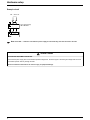
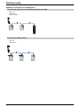
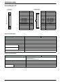
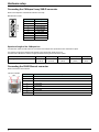
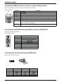
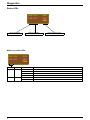
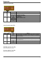
Lexium Controller
Installation Manual
Retain for future use
30072 - 452 - 86
Axis controller
Contents
Important information _________________________________________________________________________________________ 4
Documentation structure_______________________________________________________________________________________ 5
Introduction _________________________________________________________________________________________________
Presentation _____________________________________________________________________________________________
Description of LMC10/LMC20________________________________________________________________________________
Description of LMC20A**** __________________________________________________________________________________
6
6
6
7
Hardware setup _____________________________________________________________________________________________ 8
On receipt _______________________________________________________________________________________________ 8
Mounting ________________________________________________________________________________________________ 8
Connecting the power supply ________________________________________________________________________________ 9
Characteristics of the power supplies __________________________________________________________________________ 9
Connection to a master encoder_____________________________________________________________________________ 10
Connecting the Motion bus 9-way SUB-D connector _____________________________________________________________ 12
Connecting the I/O _______________________________________________________________________________________ 15
I/O connection example ___________________________________________________________________________________ 16
Connecting the CANopen 9-way SUB-D connector ______________________________________________________________ 17
Connecting the RJ45 Ethernet connector______________________________________________________________________ 17
Connecting the Modbus RJ45 connector or graphic display terminal_________________________________________________ 18
Connecting the PROFIBUS bus 9-way SUB-D connector (LMC20A1307) ____________________________________________ 18
Connecting the DeviceNet terminals (LMC20A1309) _____________________________________________________________ 18
Diagnostics ________________________________________________________________________________________________ 19
LEDs __________________________________________________________________________________________________ 19
While every precaution has been taken in the preparation of this document,
Schneider Electric assumes no liability for any omissions or errors it may contain, nor
for any damages resulting from the application or use of the information herein.
The products and options described in this document may be changed or modified at
any time, either from a technical point of view or in the way they are operated. Their
description can in no way be considered contractual.
3
Important information
PLEASE NOTE
Please read these instructions carefully and examine the equipment in order to familiarize yourself with the device before installing,
operating or carrying out any maintenance work on it.
The following special messages that you will come across in this document or on the device are designed to warn you about potential risks
or draw your attention to information that will clarify or simplify a procedure.
The addition of this symbol to a "Danger" or "Warning" safety label indicates that there is an electrical risk that will result
in injury if the instructions are not followed.
This is a safety warning symbol. It warns you of the potential risk of injury. You must comply with all safety messages that
follow this symbol in order to avoid the risk of injury or death.
DANGER
DANGER indicates an imminently hazardous situation which, if not avoided, will result in death, serious injury or equipment
damage.
WARNING
WARNING indicates a potentially hazardous situation which, if not avoided, can result in death, serious injury or equipment
damage.
CAUTION
CAUTION indicates a potentially hazardous situation which, if not avoided, can result in injury or equipment damage.
PLEASE NOTE:
Electrical equipment should be installed, operated, serviced, and maintained only by qualified personnel. No responsibility is assumed by
Schneider Electric for any consequences arising out of the use of this material.
BLMT00011 © 2008 Schneider Electric. All rights reserved.
WARNING
LOSS OF CONTROL
- The designer of any control scheme must consider the potential failure modes of control paths and, for certain critical control
functions, must provide a means to achieve a safe state during and after a path failure. Examples of critical control functions are
emergency stop and overtravel stop.
- Separate or redundant control paths must be provided for critical control functions.
- System control paths may include communication links. Consideration must be given to the implications of unanticipated transmission
delays or failures of the link.1
- Each implementation of a Lexium Motion Controller must be individually and thoroughly tested for proper operation before being
placed into service.
Failure to follow these instructions can result in death, serious injury, or equipment damage.
1. For additional information refer to NEMA ICS 1.1 (latest edition), "Safety Guidelines for the Application, Installation, and Maintenance of Solid State Control"
4
Documentation structure
This manual is part of a series describing the Lexium Motion Controller (LMC). The following
manuals may be downloaded at www.us.telemecanique.com
Installation Manual
This manual describes:
• How to install the controller
• How to connect the controller
Optional Graphic Display Terminal User's Manual This manual describes:
• How to install the graphic display terminal
• How to connect the graphic display terminal
• How to program the controller via the graphic display terminal
EasyMotion - Programming Manual (Not available in the USA)
Supplied preinstalled in the Lexium Controller, the application model associated with EasyMotion mode is a user-friendly tool that can be
used for:
• Rapid axis configuration
• Use of Manual/Automatic mode
• Creating positioning tasks
• Editing cam profiles
• Backup and recovery of the machine parameters
• Diagnostics of the motion controller and the various axes
This programming manual also contains a table of the parameters that can be accessed via the communication protocols.
MotionPro - Programming Manual
The MotionPro Programming Manual is included in the software online help.
This online help describes:
• The software interface
• IEC 1131 programming
• The function libraries (standard functions, motion control functions, application functions)
• The Lexium controller configuration screens
Modbus, Ethernet, PROFIBUS DP, and DeviceNet manuals
These manuals describe:
• Connection to the bus or network
• Diagnostics
• Software setup
• The protocol communication services
5
Introduction
Presentation
The Lexium Controller performs axis synchronization and coordination, via fieldbuses, for applications requiring control of up to
8 synchronized axes.
It includes the following standard motion control functions:
• Speed control
• Relative and absolute positioning
• Cam profiles
• Electronic gearing function for speed and position
• Linear and circular interpolation (2½D)
• Master axis via external encoder
• Distance measurement and position capture on high-speed discrete input (30 μs)
It can be easily integrated into the standard architectures available on the market. It can be connected directly via the Modbus, CANopen,
Ethernet, PROFIBUS DP, and DeviceNet communication ports.
Models
References
LMC 10
LMC 20
LMC 20A1307
LMC 20A1309
Number
of logic inputs
Number of
logic outputs
Modbus
8 (24 V DC)
8 (24 V DC)
8 (24 V DC)
8 (24 V DC)
8 (24 V DC)
8 (24 V DC)
8 (24 V DC)
8 (24 V DC)
Yes
Yes
Yes
Yes
Integrated communication
CANopen
Ethernet network
Yes
Yes
Yes
Yes
Yes
Yes
Third-party
bus
PROFIBUS
DeviceNet
Description of LMC10/LMC20
1 Signaling and diagnostic LEDs
1
2 Ethernet connector (LMC 20 only)
3
2
4
3 Encoder power supply
4 Reset button
5 Master encoder input
5
6 Modbus or graphic display terminal connector
7 Motion bus connector
6
8 Connector for logic I/O
9 Equipment grounding conductor connection
7
10 24 V power supply terminals
11 CANopen connector (LMC 20 only)
8
9
10
11
6
Introduction
Description of LMC20A****
1 Signaling and diagnostic LEDs
1
3
2 Ethernet connector
2
3 Encoder power supply
4 Reset button
4
5
5 Master encoder input
6 Modbus or graphic display terminal connector
6
7 LEDs for:
- PROFIBUS on LMC20A1307
- DeviceNet on LMC20A1309
7
8 Motion bus connector
9 Connector for logic I/O
8
9
11 24 V power supply terminals
10
11
13
10 Equipment grounding conductor connection
12
14
12 Connector for:
- PROFIBUS on LMC20A1307
- DeviceNet on LMC20A1309
13 CANopen connector
14 Address configuration switches
7
Hardware setup
On receipt
• Check that the device reference marked on the label is the same as that on the delivery note corresponding to the purchase order.
• Open the packaging and check that the device has not been damaged in transit.
• Check that the device is complete. The packaging must contain:
- The Lexium Controller
- A bag containing three removable connectors (24 V power supply, encoder power supply, I/O)
- A CD-ROM containing the documentation
- A quick reference guide
WARNING
DAMAGED CONTROLLER EQUIPMENT
Do not operate or install any controller that appears damaged.
Failure to follow these instruction can result in death, serious injury, or additional equipment damage.
Mounting
Fasten using M5 screws, or on DIN rail 35 mm (1.38 in)
40
(1.57)
=
74
(2.91)
=
(1)
75
(2.95)
140
(5.51)
151
(5.94)
5
(0.20)
136
(5.35)
(1)
LMC20A****
6
(0.24)
LMC10, LMC20
140
(5.51)
151
(5.94)
Dimensions in mm (in)
25,6
(1.01)
2 x 5,5
(0.22)
20
20
(0.79) (0.79)
3 x 5,5
(0.22)
(1) Leave sufficient space for the connectors used.
Installation recommendations
• Install the unit vertically.
50 mm
(2 in)
• Leave at least 50 mm (2 in) free space above and below the device to allow for cooling.
• Max. ambient temperature:
LMC10: 60°C
LMC20: 50°C
• Protect from condensation and keep away from any heat sources.
50 mm
(2 in)
8
Hardware setup
Grounding
General recommendations for fieldbus connectivities:
• Twisted cable needs to be used to cancel/minimize the EMC effects.
• Shield connection between the controller and the drive must be connected to the ground on both ends. In the control cabinet the ground
clamp needs to be used to connect the shield to the panel ground. On the LMC end the connector shell needs to be connected to the
shield conductor for grounding.
• Equipotential bonding conductor needs to be used if the drives are located at the remote cabinet from that of the LMC.
Recommendations on Fieldbus specific requirements for LMC:
• CanOpen, Motion Bus and DeviceNet : The Can High/ DeviceNet High signal line and Can Low / DeviceNet Low signal line must be
isolated from the system ground. The Can GND/ DeviceNet GND should be connected to the shield conductor to bring it to the same
potential as the system ground.
• Profibus: The RxD and TxD signal lines A1/B1 and A2/B2 must be isolated from the system ground.
DANGER
ELECTRIC SHOCK
This product and associated equipment must be grounded according to the above recommendations.
Failure to follow these instructions will result in death or serious injury.
Connecting the power supply
3
24 V
2
PWS
0V
Use the connector supplied in the bag:
- Max. connectable cross-section: 1.5 mm2 - AWG 16
- Max. tightening torque: 0.3 Nm (2.66 lb-in)
1
Terminal
3
2
1
Function
0V
not connected
+ 24 V
Characteristics of the power supplies
LMC10
LMC20
Nominal voltage
24 V DC
24 V DC
LMC20A ****
24 V DC
Voltage limit (including ripple)
19 ... 30 V DC
19 ... 30 V DC
19 ... 30 V DC
Nominal input current
0.3 A
0.4 A
0.5 A
9
Hardware setup
Example circuit
100 ... 240 V AC
N
L
+
-
24 V
24 V power supply
ABL7 RE2402
0V
PWS
Note: If the LMC*** controller is left without a power supply for around 20 days, the clock will have to be reset.
CAUTION
INCONSISTENT EQUIPMENT OPERATION
Ensure that the power supply does not exceed the specified voltage limits. Excessive ripple or exceeding the voltage limits will cause
inconsistent operation and may damage the LMC.
Failure to follow these instructions can result in injury or equipment damage.
10
Hardware setup
Connection to a master encoder
The Lexium Controller has a 15-way female HD SUB-D connector for connecting an encoder.
The VW3M4701 option (to be ordered separately) consists of a male connector with a 1-meter cable, with no connector on the other end,
and can be used to connect the encoder to an intermediate screw terminal block.
The master encoder input is compatible with encoders:
• RS422
• 5 V push-pull
• 5 V open collector
• SSI
Female SUB-D connector
ENCODER
Description
Encoder terminal
A+
AZ+
ZB+
BSSI data +
SSI data CLKSSI +
CLKSSI +5V
0V
+ 24 V
0V
Supply return
15 10 5
Incremental encoder
11 6
1
Absolute encoder
5 V encoder
24 V encoder
Encoder power supply
feedback (1)
Pin
1
2
4
5
10
11
1
2
6
14
15
8
7
8
13
VW3M4701 option - wire colors
red/white
brown
orange
yellow
white
purple
red/white
brown
green
light brown
light purple
pink
blue
pink
light green
black = shielding
(1) For monitoring the encoder power supply and the presence of the encoder cable. The Lexium Controller trips on a fault if the encoder
power supply feedback is missing.
Characteristics of the master encoder input
Power supply
Nominal voltage
V
5 DC or 24 DC
Nominal current
mA
500
Voltage
V
5.5 DC
Current
mA
12
Input impedance
for nominal U
kΩ
2
Isolation
V
2500
Input limit values
Incremental encoder
SSI serial absolute
encoder
_
_
_
A, A , B, B , Z, Z
Type of signal
Maximum operating
frequency
250 kHz per input x 4, or 1 MHz for counting
Number of bits
32, with configurable frame (number of turns, number of bits/turn,
binary or gray format, parity, etc)
Clock frequency
kHz
200
Clock voltage
V
5
11
Hardware setup
Encoder power supply
24 V
PWS
5V
ENC
1
2
0V
Use the connector supplied in the bag:
- Max. connectable cross-section: 1.5 mm2 - AWG 16
- Max. tightening torque: 0.3 Nm (2.65 lb-in)
3
Terminal
1
2
3
Function
+ 24 V
+5V
0V
Power
Depends on the type
of encoder used
Example circuits
110 ... 240 V AC
110 ... 240 V AC
N
L
+
-
24 V
0V
PWS
12
24 V power supply
ABL7 RE2402
24 V
0V
ENC
PWS
8
7
ENCODER
N
L
+
-
5V
0V
ENC
PWS
5 V power supply
8
15
ENCODER
Hardware setup
Connecting the Motion bus 9-way SUB-D connector
Male SUB-D connector.
9
1
6
MOTION BUS
5
Terminal
1
2
3
4
5
6
7
8
9
Description
not connected
CAN_L
CAN_GND
not connected
not connected
CAN_GND
CAN_H
not connected
not connected
The CANopen connection dedicated to the Motion bus provides the option of connecting up to 8 Lexium 05 and/or Lexium 15 servo drives
and/or SD328 stepper drives.
The Motion bus is used to control the movement of these 8 axes.
The network cycle allows that the position setpoints to be updated for axis synchronization.
LMC 10, LMC 20 and LMC 20A130* Lexium Controllers integrate the CANopen protocol dedicated to the Motion bus as standard.
For the best performance of the Motion bus, it is advisable to set it up in a daisy-chain formation, without any tap-offs; our range of
connection accessories has been extended with this in mind.
Example of architecture with the CANopen machine bus dedicated to the Motion bus
LMC *0 or
LMC 20A130*
Lexium controller
Motion bus
Lexium 05
Lexium 05
SD328
SD328
Lexium 15 Lexium 15
13
Hardware setup
Examples of connection to the Motion bus
For Lexium 05 and Lexium 15 and SD328 for customer assembly
LMC *0 or
LMC 20A130*
Lexium Controller
5
14
14
1
Lexium 05
SD328
Lexium 15
For Lexium 05, SD328 prewired
LMC *0 or
LMC 20A130*
5
2
2
Lexium 05
14
7
7
Lexium 05
SD328
Hardware setup
Connection accessories
Connectors and junction boxes
Description
Use
No.
Reference
Connector, 9-way female SUB-D with line
terminator
Connection of Lexium 15
1
VW3 M3 802
Tap (3) with 3 RJ45 connectors
Daisy-chain connection of Lexium 05
2
TCS CTN023F13M03
Use
No.
Cordsets and connection cables
Description
Length
Reference
From
To
m
Cordset with
one 9-way female SUB-D connector
and
one RJ45 connector with line terminator
LMC
Lexium controller
Lexium 05
5
Tap
TCS CTN023F13M03
1
VW3 M3 805R010
CANopen cordsets (1) with
one RJ45 connector at each end
Tap
Tap
7
TCS CTN023F13M03 TCS CTN023F13M03
0.3
TSX CAN CARR 03
50
TSX CAN CA 50
100
TSX CAN CA 100
300
TSX CAN CA 300
50
TSX CAN CB 50
100
TSX CAN CB 100
300
TSX CAN CB 300
50
TSX CAN CD 50
100
TSX CAN CD 100
300
TSX CAN CD 300
CANopen IP 20 cables (1)
14
Standard cables, CE marking
Low smoke emission, halogen-free
Flame retardant (IEC 60332-1)
UL certification, CE marking
Flame retardant (IEC 60332-2)
Cable for harsh environment (2) or mobile installation, CE marking
Low smoke emission, halogen-free
Flame retardant (IEC 60332-1)
14
14
(1) Please refer to the catalog
(2) Harsh environment:
- Resistance to hydrocarbons, industrial oils, detergents, solder splashes
- Relative humidity up to 100%
- Saline atmosphere
- Significant temperature variations
- Operating temperature between - 10°C and + 70°C
(3) Available 4th quarter 2007
15
Hardware setup
Connecting the I/O
Female connector
plug side view
INPUTS/OUTPUTS
Controller
male connector
25
26
23
24
21
22
19
20
17
18
15
16
13
14
11
12
9
10
7
8
5
6
3
4
1
2
Description
Logic input DI0
Logic input DI1
Logic input DI2
Logic input DI3
Logic input DI4
Logic input DI5
Logic input DI6
Logic input DI7
Position capture TP1
Position capture TP2
Event input EI1
Event input EI2
0V
Terminal
26
24
22
20
18
16
14
12
10
8
6
4
2
26
25
24
23
22
21
20
19
18
17
16
15
14
13
12
11
10
9
8
7
6
5
4
3
2
1
Terminal
25
23
21
19
17
15
13
11
9
7
5
3
1
Description
Logic output DO0
Logic output DO1
Logic output DO2
Logic output DO3
Logic output DO4
Logic output DO5
Logic output DO6
Logic output DO7
+ 24 V
+ 24 V
+ 24 V
0V
0V
Input characteristics
LMC10
Type of base
LMC20
8
Number of channels
24 V DC (positive logic)
Nominal voltage
19 V ... 30 V DC
Voltage limits
7 mA
Nominal input current
3 kΩ
Impedance
Filtering time
At state 1
15 μs
At state 0
70 μs
"Position capture" input filtering
time
At state 1
1 μs
At state 0
0.5 μs
Isolation
No isolation between channels, isolation with internal logic via opto-isolators
Output characteristics
LMC10
Type of base
Number of channels
Nominal voltage
19 V ... 30 V DC
Limit voltages
0.2 A per channel
Output current
Filtering time
16
LMC20
8 x 24 V DC open collector (source) logic outputs, compatible with level 1 PLC,
standard IEC 65A-68
Maximum switching voltage: 30 V
24 V DC (positive logic)
At state 1
150 μs
At state 0
250 μs
Hardware setup
I/O connection example
Using a Telefast sub-base ABE 7B20MPN22:
BJ 1
24 V
1 2
0V
3 4
J1
J1_11
J1_10
J1_8
J1_6
J1_4
BJ2_22
BJ2_11
BJ2_12
BJ2_13
BJ2_14
J1_12
BJ2_10
J1_13
BJ2_9
BJ2_21
J1_14
J1_15
BJ2_20
J1_16
BJ2_8
J1_17
BJ2_7
BJ2_19
J1_18
J1_19
BJ2_6
BJ2_18
J1_20
J1_21
BJ2_5
BJ2_17
J1_22
J1_23
BJ2_4
BJ2_16
J1_24
J1_25
BJ2_3
BJ2_15
J1_26
1
2
3
4
5
6
7
8
9
10
11
12
13
14
15
16
17
18
19
20
21
22
23
24
25
26
HE10
BJ 2
1
2
3
4
5
6
7
8
9
10
11
12
13
14
15
16
17
18
19
20
21
22 23
24
BJ 4
BJ 3
1
2
3
4
5
6
7
8
9
10
0 V + 24 V I0
I1
I2
I3
I4
I5
I6
I7
I8
I9
I10 I11
4
5
6
7
8
9
10
11
12
13
3
4
5
6
7
8
9
10
1
1
2
3
4
5
6
7
8
9
Q0
Q1
Q2
Q3
Q4
Q5
Q6
14 15
16
17
18
19
20 21
2
4
5
6
7
8
10
Q7 0 V + 24 V
BJ 2
1
2
BJ 3
3
1
2
CI0
CI1 CI2 CI3 CI4 CI5 CI6 CI7 CI8 CI9 CI10 CI11 CQ0 CQ1 CQ2 CQ3 CQ4 CQ5 CQ6 CQ7
(1)
3
22 23
1
(1)
9 10
24
BJ 4
1
(1) Install interference suppressors on inductive circuits such as relays.
U
A prefabricated connection cable with two HE10 connectors can be used to connect the Lexium Controller and the Telefast sub-base:
• ABF T26B050 0.5 m (1.64 ft)
• ABF T26B100 1 m (3.28 ft)
• ABF T26B200 2 m (6.56 ft)
17
Hardware setup
Connecting the CANopen 9-way SUB-D connector
Refer to the EasyMotion and MotionPro software online help.
5
9
1
6
CANopen
Male SUB-D connector
Terminal
1
2
3
4
5
6
7
8
9
Description
not connected
CAN_L
CAN_GND
not connected
not connected
CAN_GND
CAN_H
not connected
not connected
Speed and length of the CANopen bus
It is essential to make sure that all devices connected to the CANopen bus operate at the same transmission speed.
The maximum length of the CANopen bus depends on the transmission speed on this bus.
The table below indicates the maximum lengths permitted according to the transmission speed:
Transmission speed
50 kbps
125 kbps
250 kbps
500 kbps
1 Mbps
Max. length of bus
1,000 m
(3,281 ft)
500 m
(1,640 ft)
250 m
(820 ft)
100 m
(328 ft)
20 m
(66 ft)
Connecting the RJ45 Ethernet connector
Refer to the Ethernet User's Manual.
View from sub-base
side
1.......................8
ETHERNET
18
Terminal
1
TD+
Description
2
TD-
3
RD+
4
not connected
5
not connected
6
RD-
7
not connected
8
not connected
Hardware setup
Connecting the Modbus RJ45 connector or graphic display terminal
Refer to the Modbus User's Manual or the Graphic Display Terminal User's Manual.
View from sub-base
side
1.......................8
Terminal
1
not connected
2
not connected
3
not connected
4
B signal (RS485) = V1 signal (Modbus)
5
A signal (RS485) = V0 signal (Modbus)
6
not connected
7
Modbus VP signal
12 V DC power supply provided by the Motion Controller (only for supplying an RS485/RS232
converter or a graphic display terminal)
8
Modbus common signal
0V
MODBUS
Description
Connecting the PROFIBUS bus 9-way SUB-D connector (LMC20A1307)
Refer to the PROFIBUS User's Manual.
Female SUB-D connector
1
6
5
9
Terminal
1
2
3
4
5
6
7
8
9
Description
not connected
not connected
RxD/TxD-N (Reception/Transmission -)
not connected
DGND (ground)
VP (5 volts)
not connected
RxD/TxD-P (Reception/Transmission +)
not connected
Connecting the DeviceNet terminals (LMC20A1309)
Refer to the DeviceNet User's Manual.
1
2
3
4
5
1
Terminal
1
2
3
4
5
Name
VCAN_L
SHIELD
CAN_H
V+
2
3
Color
black
blue
none
white
red
4
5
Function
common
signal
shielding
signal
power supply
19
Diagnostics
Status LEDs
Motion bus status
RUN RUN
RUN
ERR ERR
ERR
PWS
CANopen bus status
Lexium Controller status
Motion bus status LEDs
RUN RUN
RUN
ERR ERR
ERR
PWS
Marking
RUN
Color
Green
Status
Off
Meaning
No CAN master configured
Flashing
The Motion bus is in initialization phase
1 flash per second The Motion bus is stopped
On
The Motion bus is operational
ERR
Red
Off
Flashing
20
No Motion bus fault
Motion bus fault
Diagnostics
CANopen bus status LEDs
RUN RUN
RUN
ERR ERR
ERR
PWS
Marking
RUN
Color
Green
Status
Off
Meaning
No CAN master configured
Flashing
The CANopen bus is in initialization phase
1 flash per second The CANopen bus is stopped
On
The CANopen bus is operational
ERR
Red
Off
No CANopen fault
Flashing
CANopen configuration not valid
1 flash per second Alarm threshold exceeded (too many errors)
2 flashes per second A "Node Guarding" or "Heartbeat" event has occurred
On
The CANopen bus is stopped (BUS OFF)
Lexium Controller status LEDs
RUN RUN
RUN
ERR ERR
ERR
PWS
Marking
RUN
Color
Green
Status
Off
Flashing
ERR
Red
Yellow
The Lexium Controller is in STOP state or locked by a software error. The application
program is not executed.
On
The Lexium Controller is in RUN state. The application program is executed.
Off
No fault
Flashing
PWS
Meaning
The Lexium Controller is not configured (application missing, invalid or incompatible)
Minor Lexium Controller fault or application fault (event-triggered task cycle time too long,
encoder supply fault, etc.).
On
Lexium Controller hardware fault or serious application fault (watchdog, etc.)
Off
Lexium Controller off
On
Lexium Controller on
PROFIBUS (LMC20A 1307) LEDs
Refer to the PROFIBUS User's Manual
DeviceNet (LMC20A 1309) LEDs
Refer to the DeviceNet User's Manual.
21
30072 - 452 - 86
08.2008