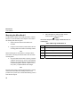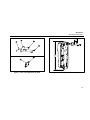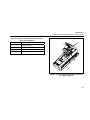
1
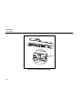
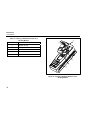
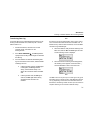
MicroDock II
Automatic Test and Calibration Station
User Manual
D5617 English
iERP: 115698
© 2004 BW Technologies. All rights reserved. Printed in Canada.
All product names are trademarks of their respective companies.
Limited Warranty & Limitation of Liability
BW Technologies Ltd. (BW) warrants this product to be free from defects in material and workmanship under normal use and service for a period of two years,
beginning on the date of shipment to the buyer. This warranty extends only to the sale of new and unused products to the original buyer. BW’s warranty
obligation is limited, at BW’s option, to refund of the purchase price, repair, or replacement of a defective product that is returned to a BW authorized service
center within the warranty period. In no event shall BW’s liability hereunder exceed the purchase price actually paid by the buyer for the Product.
This warranty does not include:
a) fuses, disposable batteries or the routine replacement of parts due to the normal wear and tear of the product arising from use;
b) any product which in BW’s opinion, has been misused, altered, neglected or damaged by accident or abnormal conditions of operation, handling or use;
c) any damage or defects attributable to repair of the product by any person other than an authorized dealer, or the installation of unapproved parts on the
product; or
The obligations set forth in this warranty are conditional on:
a) proper storage, installation, calibration, use, maintenance and compliance with the product manual instructions and any other applicable
recommendations of BW;
b) the buyer promptly notifying BW of any defect and, if required, promptly making the product available for correction. No goods shall be returned to BW
until receipt by the buyer of shipping instructions from BW; and
c) the right of BW to require that the buyer provide proof of purchase such as the original invoice, bill of sale or packing slip to establish that the product is
within the warranty period.
THE BUYER AGREES THAT THIS WARRANTY IS THE BUYER’S SOLE AND EXCLUSIVE REMEDY AND IS IN LIEU OF ALL OTHER WARRANTIES,
EXPRESS OR IMPLIED, INCLUDING BUT NOT LIMITED TO ANY IMPLIED WARRANTY OF MERCHANTABILITY OR FITNESS FOR A PARTICULAR
PURPOSE. BW SHALL NOT BE LIABLE FOR ANY SPECIAL, INDIRECT, INCIDENTAL OR CONSEQUENTIAL DAMAGES OR LOSSES, INCLUDING
LOSS OF DATA, WHETHER ARISING FROM BREACH OF WARRANTY OR BASED ON CONTRACT, TORT OR RELIANCE OR ANY OTHER THEORY.
Since some countries or states do not allow limitation of the term of an implied warranty, or exclusion or limitation of incidental or consequential damages, the
limitations and exclusions of this warranty may not apply to every buyer. If any provision of this warranty is held invalid or unenforceable by a court of competent
jurisdiction, such holding will not affect the validity or enforceability of any other provision.
BW Technologies Ltd.
2840 – 2nd Avenue SE
Calgary, AB T2A 7X9
Canada
BW Technologies Inc.
3279 West Pioneer Parkway
Arlington, TX 76013
USA
BW Europe Ltd.
101 Heyford Park
Upper Heyford, Oxfordshire OX25 5HA
United Kingdom
Table of Contents
Title
Page
Introduction............................................................................................................................................ 1
Contacting BW Technologies................................................................................................................ 2
Safety Information - Read First ............................................................................................................. 2
Getting Started ...................................................................................................................................... 4
Installation ............................................................................................................................................. 7
How to Use the Base Station ................................................................................................................ 9
Activating the Station..................................................................................................................... 9
Deactivating the Station .............................................................................................................. 10
Eventlogging ....................................................................................................................................... 10
User Option Menu ............................................................................................................................... 11
Time/Date ................................................................................................................................... 12
Inlet Setup ................................................................................................................................... 12
Pump Setup................................................................................................................................. 13
Contrast ....................................................................................................................................... 13
Backlight ..................................................................................................................................... 13
About ........................................................................................................................................... 13
Format MMC................................................................................................................................ 14
Inlet Select................................................................................................................................... 14
Pass Code ................................................................................................................................... 14
Language..................................................................................................................................... 14
i
MicroDock II
Users Manual
Title
Page
Adding Another Docking Module ........................................................................................................15
Mounting the MicroDock II ..................................................................................................................20
Inserting a GasAlertClip Extreme into a Docking Module...................................................................22
Changing Dipswitch Settings on the GasAlertClip Extreme Docking Module ....................................24
Inserting a GasAlert Extreme into a Docking Module .........................................................................29
Transferring Data Log..................................................................................................................31
Inserting a GasAlertMicro into a Docking Module...............................................................................32
Charging ..............................................................................................................................................34
Charging the GasAlertMicro Battery Pack...................................................................................35
Reconfiguring the GasAlertMicro Detector .........................................................................................37
Changing Settings .......................................................................................................................37
After Reconfiguration of Detector and Before Bump/Calibration ........................................................39
Accessing an MMC Card from a PC while Another Test is Being Ran.......................................40
Bump Check and Calibration ..............................................................................................................41
Guidelines ...................................................................................................................................41
Bump Check ................................................................................................................................42
Calibration (GasAlertMicro and GasAlert Extreme only).............................................................43
ii
Title
Page
Access Test Results............................................................................................................................ 44
Accessing Test Results without Fleet Manger - Windows 98, SE, 2000 .................................... 44
Accessing Test Results without Fleet Manager - Windows XP .................................................. 44
System Requirements ................................................................................................................. 44
Maintenance........................................................................................................................................ 45
Battery Pack Storage................................................................................................................... 45
Battery Replacement ................................................................................................................... 46
Inserting an MMC Card ............................................................................................................... 47
Troubleshooting .................................................................................................................................. 48
Replacement Parts and Accessories.................................................................................................. 54
Specifications ...................................................................................................................................... 55
Charger Specifications ................................................................................................................ 56
iii
MicroDock II
Users Manual
iv
List of Tables
Table
Title
1.
2.
3.
4.
5.
6.
7.
8.
9.
10.
11.
12.
13.
14.
15.
16.
17.
18.
19.
20.
21.
International Symbols ........................................................................................................ 3
The MicroDock II................................................................................................................ 5
Onscreen Icons.................................................................................................................. 6
GasAlertClip Extreme Docking Module Pushbuttons ........................................................ 6
GasAlertMicro Docking Module Pushbuttons .................................................................... 6
GasAlert Extreme Docking Module Pushbuttons .............................................................. 7
Station Connections........................................................................................................... 8
Adding Another Docking Module ..................................................................................... 15
Mounting the MicroDock II ............................................................................................... 20
Inserting a GasAlertClip Extreme Detector into a Docking Module................................. 23
Changing Dipswitch Settings ........................................................................................... 25
Dipswitch Settings............................................................................................................ 25
Inserting a GasAlert Extreme into a Docking Module...................................................... 30
Inserting a GasAlertMicro Detector into a Docking Module ............................................ 33
Charger Status LED......................................................................................................... 35
Audible Alarm................................................................................................................... 35
Charging a GasAlertMicro ............................................................................................... 36
Battery Replacement ....................................................................................................... 46
Replacing the MMC Card ................................................................................................ 47
Troubleshooting Tips ....................................................................................................... 48
Replacement Parts and Accessories............................................................................... 54
Page
v
MicroDock II
Users Manual
vi
List of Figures
Figure
1.
2.
3.
4.
5.
6.
7.
8.
9.
10.
11.
12.
13.
14.
15.
16.
Title
Page
The MicroDock II.......................................................................................................................... 5
Station Connection....................................................................................................................... 8
Option Menus............................................................................................................................. 11
Adding Another Docking Module (top)....................................................................................... 16
Adding Another Docking Module (bottom)................................................................................. 17
Attaching Bottom Cover Plate.................................................................................................... 18
Parts of the Wall Mounting Plate ............................................................................................... 21
Attaching the Wall Mounting Plate............................................................................................. 21
Inserting a GasAlertClip Extreme Detector into a Docking Module........................................... 23
Detaching the GasAlertClip Extreme Module ............................................................................ 26
Detaching Bottom Cover Plate .................................................................................................. 27
Changing Dipswitch Settings ..................................................................................................... 28
Inserting a GasAlert Extreme into a Docking Module................................................................ 30
Inserting a GasAlertMicro Detector into a Docking Module ...................................................... 33
Battery Replacement ................................................................................................................. 46
Replacing the MMC Card .......................................................................................................... 47
vii
MicroDock II
Users Manual
viii
a CAUTION
MicroDock II Station with 1 GasAlertMicro Charging
Module
FOR SAFETY REASONS, THIS EQUIPMENT MUST BE
OPERATED AND SERVICED BY QUALIFIED PERSONNEL
ONLY. READ AND UNDERSTAND THE USER MANUAL
COMPLETELY BEFORE OPERATING OR SERVICING.
Order Number
Standard MicroDock II Kit includes:
•
Shipping case
•
MicroDock II base station and docking modules as
specified
•
Deluxe Fleet Management software
•
110 – 240 VAC universal power adapter
•
32 MB MultiMediaCard (MMC) installed
•
Set of four C-cell alkaline batteries
•
Excel Datalog Manager software
•
USB connector cable
Description
DOCK2-2-1B1C-00-N
Base unit and module only
DOCK2-2-1B1C-02-N
Kit with 34 l gas
DOCK2-2-1B1C-04-N
Kit with 58 l gas
MicroDock II Station with 1 GasAlertClip Extreme H2S
Module
Order Number
Description
DOCK2-2-1E-00-N
Base unit and module only
DOCK2-2-1E-05-N
Kit with 34 l gas
DOCK2-2-1E-06-N
Kit with 58 l gas
MicroDock II Station with 1 GasAlert Extreme Module
Order Number
Description
•
Fresh air inlet filter
DOCK2-2-1D-00-N
•
Two 2 ft./0.6 m calibration gas hoses
DOCK2-2-1D-05-N
Kit with 34 l gas
•
Two gas cylinder inlet fittings, and
DOCK2-2-1D-06-N
Kit with 58 l gas
•
Operators guide
ix
Base unit and module only
MicroDock II
Users Manual
MicroDock II Kit’s (cont.)
MicroDock II Station with 2 GasAlertMicro Charging
Modules
Order Number
Description
DOCK2-2-2B1C-00-N
Base unit and module only
DOCK2-2-2B1C-04-N
Kit with 58 l gas
MicroDock II Station with 1 GasAlertMicro Charging
Module and 1 GasAlertClip Extreme H2S Module
Order Number
Description
DOCK2-2-1B1C1E-00-N
Base unit and module only
DOCK2-2-1B1C1E-04-N
Kit with 58 l gas
MicroDock II Station with 1 GasAlertMicro Charging
Module, 1 GasAlertClip Extreme H2S Module, and 1
GasAlert Extreme Module
Order Number
Description
DOCK2-3-1B1C1D1E-00-N
Base unit and module only
DOCK2-3-1B1C1D1E-04-N
Kit with 58 l gas
Add suffix (-A) for Australia mains plug, (-CH) for Switzerland
mains plug, (-E) for Europe mains plug, (-U) for United
Kingdom mains plug.
x
MicroDock II
Introduction
a Warning
To ensure your personal safety, read “Safety
Information” before you use the MicroDock II.
The MicroDock II Automatic Test and Calibration Station
(“the station”) provides automated calibration and bump
testing for the GasAlertClip Extreme, GasAlert Extreme, and
GasAlertMicro detectors. The system is expandable to
include up to 10 docking modules.
1
MicroDock II
Users Manual
Contacting BW Technologies
Safety Information - Read First
To contact BW Technologies, call:
Use the station only as specified in this manual.
1-888-749-8878 USA
1-800-663-4164 Canada
+44 (0) 1869 233004 Europe
+971-4-8871766 Middle East
+61-438-887-232 Australia
+852-2974-1783 China
+65-9737-2005 South East Asia
+1-403-248-9226 other countries
International symbols used on the station and in this manual
are explained in Table 1.
Address correspondence to:
BW Technologies Ltd.
2840 – 2 Avenue S.E.
Calgary, AB T2A 7X9
CANADA
ISO 9001
2
Read the Caution statements on the following pages before
using the station.
ec Note
This instrument contains batteries. Do not mix with the
solid waste stream. Spent batteries should be disposed
of by a qualified recycler or hazardous materials handler.
MicroDock II
Safety Information – Read First
a Caution
⇒ If the station is damaged or something is missing, contact BW Technologies immediately.
⇒ We recommend that the station be attached to a venting system or that the station be used in a well-ventilated
area.
⇒ The maximum recommended exhaust line length is 50 ft. (15.24 m).
⇒ Confirm that the inlet filter is clean.
⇒ Confirm that all gas bottles contain enough gas.
⇒ A demand flow regulator must be used with all gas bottle connections.
⇒ Calibrate and bump only in a clean atmosphere that is free of background gas, otherwise connect a zero air bottle
to the zero air inlet on the station.
⇒ Do not expose the station to electrical shock and/or severe continuous mechanical shock.
⇒ The station warranty will be void if the unit is disassembled, adjusted, or serviced by non-BW Technologies
personnel.
⇒ Do not immerse the station in liquids.
Table 1. International Symbols
Symbol
X
Meaning
Conforms to European Union directives
3
MicroDock II
Users Manual
Getting Started
To order replacement parts, see the section Replacement
Parts and Accessories.
The following items are included with your station. If the
station is damaged or something is missing, contact the
place of purchase immediately.
To become familiar with the features and functions of the
station, study the following figures and tables.
•
Batteries (four replaceable C-cell alkaline batteries)
•
MultiMediaCard (installed)
•
USB cable
•
Two calibration gas hoses with quick connect fittings
•
Inlet filter assembly
•
Power adapter
•
Quick reference guide
•
Fleet Manager Deluxe CD
•
Charge adapter (charger models only)
4
•
Figure 1 and Table 2 describe the station.
•
Table 3 describes the station’s onscreen icons.
•
Tables 4, 5, and 6 describe the docking module’s
pushbuttons.
MicroDock II
Getting Started
Table 2. The MicroDock II
A
B
J
C
D
E
K
A
LCD display
B
Zero air/purge inlet (inlet 1)
C
Calibration gas inlet (inlet 2)
D
Activation buttons
E
Base station
F
Power connection
G
USB connection
M
H
Charger connection (charger model)
N
I
Description
L
F
G
H
Item
O
Figure 1. The MicroDock II*
Note
A standard MicroDock II base station comes with two inlets.
A maximum of four calibration gas inlets can be specified by
the user before manufacturing.
I
Battery cover
J
Docking module lid
K
Exhaust outlet
L
Detector bay
M
Charger status LED (charger model)
N
Docking module
O
Docking module activation buttons and
status LEDs
*GasAlertMicro charger module shown
5
MicroDock II
Users Manual
Table 3. Onscreen Icons
Icon
Function
Alternating current
Table 4. GasAlertClip Extreme Docking Module
Pushbuttons
Pushbutton
Batteries full
Batteries half-charged
Batteries depleted
C
Description
•
To bump a detector, press
BUMP CHECK C.
•
When connecting a new
docking module, press and hold
BUMP CHECK C to send a
confirmation signal back to the
base station.
BUMP CHECK
MultiMediaCard (MMC)
MultiMediaCard (MMC) not installed
Test pass
Test fail
Time/date pointer
Table 5. GasAlertMicro Docking Module Pushbuttons
Pushbutton
Scroll up
Scroll down
Selection arrow
C
BUMP CHECK
Selected feature
Pass code protected
C
CALIBRATION
6
Description
•
To bump a detector, press
BUMP CHECK C.
•
When connecting a new
docking module, press and hold
BUMP CHECK C to send a
confirmation signal back to the
base station.
To calibrate a detector, press
CALIBRATION C.
MicroDock II
Installation
Table 6. GasAlert Extreme Docking Module
Pushbuttons
Pushbutton
C
BUMP CHECK
C
CALIBRATION
C
DATA
TRANSFER
Description
•
To bump a detector, press
BUMP CHECK C.
•
When connecting a new
docking module, press and hold
BUMP CHECK C to send a
confirmation signal back to the
base station.
Installation
•
A demand flow regulator must be used with all gas bottle
connections.
•
The exhaust line must not be connected to a negative
pressure system.
•
The maximum recommended exhaust line length is 50 ft.
(15.24 m).
•
Attach all gas connections. Inlet 1 is configured for
ambient air and inlet 2 to 5 is configured for
calibration/test gas.
•
If the atmosphere is not free of background gas, connect
a zero air bottle to inlet 1.
•
This product is designed for installation in a generalpurpose location. All required national electrical codes
and safety standards must be followed.
To calibrate a detector, press
CALIBRATION C.
To transfer data log from the
GasAlert Extreme detector, press
DATA TRANSFER C.
7
MicroDock II
Users Manual
•
Plug the station into an AC outlet or refer to the
Maintenance section for battery installation instructions.
•
For AC main installation, a circuit breaker shall be
included in the building installation as a disconnect
device for the equipment. The disconnect device shall be
installed in close proximity to the equipment and the
device shall be marked as a disconnecting means for the
equipment.
•
Refer to the accompanying Fleet Manager support CD for
PC software installation and user instructions.
Table 7. Station Connections
Item
8
Description
A
Inlet filter assembly
B
Calibration gas hose
C
Demand flow regulator
D
Gas cylinder
E
Power jack
F
USB jack
G
Gas outlet
H
Charger connection (GasAlertMicro only)
Figure 2. Station Connection
MicroDock II
How to Use the Base Station
How to Use the Base Station
Since the base station pushbuttons are not labelled, you
need to refer to the LCD. You can operate the station by
pressing the pushbutton under the corresponding option.
Activating the Station
To activate the station, connect power or if power is
connected, press and hold the left most button C on the
base station until the screen below appears.
Shortly after, the following screen or one similar will appear:
Initialization
The station performs an initialization on startup that lasts
approximately 4 seconds.
The MultiMediaCard (MMC) icon is displayed continuously
when the card is present. The MMC records various
MicroDock II information.
If the station is pass code protected,
is displayed.
Confirming Inlet Setup
Once the station is activated for its first time, ensure that the
inlets are setup properly.
•
Inlet 1 will always be purged.
•
Unless specified at the time of order, inlet 2
will be defaulted to quad gas mix.
•
Inlets 3 – 5 (if installed) will always be purged.
To confirm that the inlets are accurately set, locate your
inlets under the user option menu of your station and verify,
or see Inlet Setup to learn more about proper setup
instructions.
a Warning
If the inlets are not setup properly, failed tests could
result.
The batteries are tested on activation and continuously after.
If battery power is extremely low, flashes.
9
MicroDock II
Users Manual
Deactivating the Station
Results History (Log)
To turn off the station, press and hold the right most button
C for approximately 1 second.
This option displays the results of the last 10 records, in total,
of bump and calibration tests. The results will be displayed
from most recent to the least. Test errors will be displayed as
the type of error (i.e. Unit error, MMC error).
Note
The power down sequence is quick. You may not notice the
power down screen.
Eventlogging
The Result History is not saved when the station is powered
down.
All bump tests and calibrations are recorded on a
MultiMediaCard (MMC). The MMC is a card in the base
station that stores test records.
The GasAlertMicro will turn off approximately 25 minutes
after a bump or calibration if no activity is detected.
Saved test records can be downloaded from the MicroDock II
station to a PC.
Refer to the accompanying Fleet Manager support file for PC
software installation and user instructions.
10
MicroDock II
User Option Menu
User Option Menu
The station has the following user options:
1.
Time/Date
2.
Inlet setup
3.
Pump setup
4.
Contrast
5.
Backlight
6.
About
7.
Format MMC
8.
Inlet select
9.
Pass code
10. Language
Note
Bump or calibration tests performed while the user option
menu is activated are initiated once the menu is exited.
To access the user options menu, press and hold menu C
for approximately 1 second.
Press or to navigate between options. Press sel C to
select the option.
To exit the options menu and return to the main screen,
press exit C.
Figure 3. Option Menus
11
MicroDock II
Users Manual
Time/Date
Inlet 1
The Time/Date option allows you to modify the time and date
of your station.
To toggle between ambient and zero air, press sel C once
with the arrow beside inlet 1. An asterisk appears to indicate
that the selection can be modified. Press or to toggle the
selection.
Press sel C to navigate between months, days, years,
hours, and minutes. You can change the date and time by
pressing . Press exit C to save the new information.
Note
MicroDock II allows the user to determine the actual day of
the week; this is represented by the letter “d” located at the
end of the second line. 1 = Monday, 2 = Tuesday etc.
Inlet Setup
The station is shipped with the zero air inlet (inlet 1)
configured for ambient air and the calibration gas inlet
(inlet 2) configured for the standard four-gas mixture. The lot
number on the gas cylinders for both the zero gas and the
four-gas mixture can be entered, if desired.
Press to navigate between inlet’s 1 and 2. Press sel C to
select the inlet.
12
If you activated the zero gas option, press to move the
arrow to the lot number. Press sel C to change the lot
number. Press or to choose the desired number and
press sel C to navigate to the next number. Press exit C to
save the new lot number.
Inlet 2
If you choose inlet 2, it automatically brings you to the gas
species.
•
Press or to choose the desired gas and press
sel C confirm.
•
To change the concentration, navigate the
selection arrow using or and press sel C.
•
Press exit C to save the new lot number.
MicroDock II
User Option Menu
Note
4 gas and 4 gas equivalent should always be 50% LEL, 18%
oxygen, 25 ppm hydrogen sulfide, and 100 ppm carbon
monoxide.
Backlight
This option allows you to adjust the lighting of the LCD.
Whenever you press sel C on the Backlight option, it
toggles the backlight on, off, and auto. The station is shipped
with the backlight on auto.
Pump Setup
This option controls the stations pump speed. The or
arrows will increase or decrease the speed of the pump. exit
will save the selected speed. The station is factory set and
recommended at 350ml/min. Pump speed only needs to be
modified if more modules are added.
Note
When running under battery power, the Off or Automatic
mode is recommended to conserve the battery.
About
About displays the software version of the station and each
individual docking module.
Contrast
Contrast allows you to adjust the screen by pressing or .
Press reset C to set the contrast to its default setting. Press
exit C to save the new setting. The station is shipped with
the contrast set to a medium level.
13
MicroDock II
Users Manual
Format MMC
Pass Code
If you insert an unformatted MMC card, the following screen
will appear. You can choose to format the MMC card at
anytime from the menu. All data will be erased.
Pass Code Protection prevents unauthorized access to the
user option menu. is lit on a pass code protected unit.
If you choose yes, the following screen will appear. Once the
formatting is complete, you will be taken back to the menu
screen.
Inlet Select
Inlet Select allows you to select your gas inlet. If auto is
chosen, the station will automatically select the correct gas
bottle for the test.
14
Language
The station is shipped with English as the default language.
Press or to choose the desired language and press sel
C to select.
MicroDock II
Adding Another Docking Module
Adding Another Docking Module
6.
Fasten the bottom cover plate to the space
between the two docking modules using six Philips
flat-head screws.
a Warning
No more than 10 modules can be docked together at a
time.
To add another docking module, follow steps #1-6 outlined
below and refer to the following table and three figures.
Table 8. Adding Another Docking Module
Item
Description
A
Phillips pan-head screw
1.
Turn off (power down) the station.
B
End plate
2.
Remove the CPC quick connector. Gently rocking
the connector back and forth may help free it.
C
CPC quick connector
D
Barbed fitting ports
Remove the three Phillips pan-head screws from
the top and the three Philips flat-head screws from
the bottom of the end plate.
E
Gasket block
F
Phillips flat-head screw
G
PCB connectors
4.
Attach the new docking module. Only one module
can be connected at a time. Ensure the barbed
fitting ports mate properly with the gasket block.
Also ensure that the male and female PCB
connectors mate properly.
H
Bottom cover plate
5.
Attach the end plate with the Phillips screws to the
end of the new docking module after all modules
have been attached. Attach the CPC quick
connector to the end of the new docking module.
3.
15
MicroDock II
Users Manual
A
B
C
Figure 4. Adding Another Docking Module (Top)
16
MicroDock II
Adding Another Docking Module
Figure 5. Adding Another Docking Module (Bottom)
17
MicroDock II
Users Manual
H
F
Figure 6. Attaching Bottom Cover Plate
18
MicroDock II
Adding Another Docking Module
Configuring the New Docking Module
1.
Press and hold Bump Check C on the newly
inserted docking module and power-up the station
to initialize the added docking module.
2.
All the LEDs on the docking module will light. When
the information below appears on the LCD, it
indicates that the new docking module has been
successfully added.
3.
4.
Enter the user option menu and select
Pump Setup.
5.
Measure airflow through the station at inlet 1.
6.
Press
ml/m.
7.
Press exit C to save the new value.
or
to adjust airflow to approximately 350
Press Ok C to save the setting.
19
MicroDock II
Users Manual
Mounting the MicroDock II
The MicroDock II station can be easily mounted to a secure
surface. To mount the station, follow steps #1-4 and refer to
the following table and two figures.
1.
Select a secure location for the station to be
mounted.
2.
Using the screws that are provided, attach the wall
mounting plates to the station and docking module.
Note
When mounting two or more stations or docking modules,
each station or docking module will need its own set of wall
mounting plates.
3.
Once the plates are mounted on properly, measure
a distance of 60.32 mm (2.375 in.) for the retaining
screws. If you are mounting two or more units that
are attached together, measure a distance of 41.7
mm (1.64 in.) of space between each charger.
Note
Because of the variety of surfaces that the station or docking
module can be mounted onto, retaining screws are not
provided. It is up to the user to decide what retaining screw is
best suited for support.
20
4.
Attach the station or docking module onto the
secure surface by using four screws.
a Caution
Do not over torque screws. Apply a maximum of 9 to 10
in-lbs torque.
Table 9. Mounting the MicroDock II
Item
Description
A
Foam spacer
B
Wall mounting plate
C
Grommet
D
Phillips self-tapping screw (4)
MicroDock II
Mounting the MicroDock II
2.375"
10.83"
Figure 7. Parts of the Wall Mounting Plate
Figure 8. Attaching the Wall Mounting Plate
21
MicroDock II
Users Manual
Inserting a GasAlertClip Extreme into a
Docking Module
When inserting a GasAlertClip Extreme into a docking
module, follow steps #1-6 and refer to the following table and
figure. Ensure that the station is on.
1.
Press the two release tabs on the docking module
and rotate the lid up.
2.
Activate the detector and wait until it is in normal
operating mode.
3.
Adjust the alligator clip ring so that it is slightly pulled
towards you. This will prevent disruptions with the IR
transmission.
4.
Insert the detector into the detector bay.
5.
Rotate the lid down until there is a clicking sound on
both release tabs.
6.
On the LCD, the station identifies which type of
detector is in the docking module bay.
Note
To bypass the station identification screen, press any button
on the base station.
Infrared light or intense ambient light may interfere with
station/detector communication (i.e. direct sunlight, quartz
halogen lights).
22
MicroDock II
Inserting a GasAlertClip Extreme into a Docking Module
Table 10. Inserting a GasAlertClip Extreme Detector
into a Docking Module
Item
Description
A
Alligator clip ring
B
Docking module lid
C
Release tabs
D
Detector bay
B
A
C
D
Figure 9. Inserting a GasAlertClip Extreme Detector
into a Docking Module
23
MicroDock II
Users Manual
Changing Dipswitch Settings on the
GasAlertClip Extreme Docking Module
a Warning
Changing the dipswitch settings is made only for the
GasAlertClip Extreme docking module.
4.
Remove the three Phillips pan-head screws from
the top and the six Philips flat-head screws from the
bottom cover plate.
5.
Gently pull apart the station and docking module,
separating the two units from each other.
6.
Configure the gas setting by flipping the
dipswitches to the desired gas to be measured
(refer to Dipswitch Settings table).
7.
Attach the new docking module. Fasten the bottom
cover plate using the six Phillips flat-head screws.
Fasten the remaining three Phillips pan-head
screws to the top of the docking module.
The GasAlertClip Extreme docking module comes configured
so the user may change the gas being bumped.
To change the dipswitch setting on a GasAlertClip Extreme
docking module, follow steps #1-7 and refer to the following
two tables and three figures.
2.
Turn off (power down) the station.
3.
Remove the CPC quick connector. Gently rocking
the connector back and forth may help free it.
Note
When reattaching the docking module, make sure the barbed
tubing is inserted correctly.
Make sure to properly label the gas specie on the docking
module.
24
MicroDock II
Changing Dipswitch Settings on the GasAlertClip Extreme Docking Module
Table 11. Changing Dipswitch Settings
Item
Description
A
Bottom cover plate
B
Phillips flat-head screw
C
Phillips pan-head screw
D
Barbed tubing
E
Dipswitch
Table 12. Dipswitch Settings
Gas Species
Dipswitch Setting
Sulphur dioxide (SO2)
Oxygen (O2)
Hydrogen sulfide (H2S)
Carbon monoxide (CO)
25
MicroDock II
Users Manual
A
B
C
Figure 10. Detaching the GasAlertClip Extreme Module
26
MicroDock II
Changing Dipswitch Settings on the GasAlertClip Extreme Docking Module
A
B
Figure 11. Detaching Bottom Cover Plate
27
MicroDock II
Users Manual
D
E
Figure 12. Changing Dipswitch Settings
28
MicroDock II
Inserting a GasAlert Extreme into a Docking Module
Inserting a GasAlert Extreme into a
Docking Module
When inserting a GasAlert Extreme into a docking module,
follow steps #1-6 and refer to the following table and figure.
Ensure that the station is on.
1
Press the two release tabs on the docking module
and rotate the lid up.
2
Activate the detector and wait until it is in normal
operating mode.
3
Adjust the alligator clip ring so that it is slightly pulled
towards you. This will prevent disruptions with the IR
transmission.
4
Insert the detector into the detector bay.
5
Rotate the lid down until there is a clicking sound on
both release tabs.
6
On the LCD, the station identifies which type of
detector is in the docking module bay.
Note
To bypass the station identification screen, press any button
on the base station.
Infrared light or intense ambient light may interfere with
station/detector communication (i.e. direct sunlight, quartz
halogen lights).
29
MicroDock II
Users Manual
Table 13. Inserting a GasAlert Extreme into a
Docking Module
Item
Description
A
Alligator clip ring
B
Docking module lid
C
Release tabs
D
Detector bay
E
Data transfer
B
A
C
D
E
Figure 13. Inserting a GasAlert Extreme into a
Docking Module
30
MicroDock II
Inserting a GasAlert Extreme into a Docking Module
Transferring Data Log
To transfer data log from a GasAlert Extreme detector to the
docking module and MMC card, follow steps #1-5. Ensure
that the station is on.
1.
Activate the detector, wait until it is in normal
operating mode, and insert it into the
docking module.
2.
Press DATA TRANSFER C. The Run light blinks
rapidly and the docking module begins to download
the data log.
3.
Once the detector has finished downloading data
log from the detector to the station, either the Pass
or Fail light turns on.
a.
If data log transfer passes, the Pass light
is solid green, the Run light flashes
slowly, and the detector beeps. The
station will now transfer data to the MMC
card.
b.
If data log transfer fails, the Fail light is
solid red, the Run light flashes slowly,
and data transfer will need to be
restarted.
Note
If a failure occurs during data transfer, there is still a chance
some of the data has been transferred to the MMC card. To
determine if any data has been transferred, access the MMC
card data using Fleet Manager.
4.
When the station is ready to transfer data log to the
MMC card, both the Run and Pass lights are solid
and the following screen is displayed.
5.
When the transfer of data log successfully passes,
the following screen appears. Press the button C
found under Pass to return to the main menu.
Note
The MMC card can only store up to 10 data logs at any given
time. Make sure to transfer results to Fleet Manager after the
10th log. Depending on the amount of information stored on
the detector, transferring of data can take up to 20 minutes to
complete. Data log is not recorded in Results History.
31
MicroDock II
Users Manual
Inserting a GasAlertMicro into a
Docking Module
6.
Rotate the lid down until there is a clicking sound
on both release tabs.
When inserting a detector into a docking module, follow
steps #1-7 and refer to the following table and figure. Ensure
that the station is on.
7.
On the LCD, the station identifies which type of
detector is in the docking module bay and its serial
number.
1.
Press the two release tabs on the docking module
and rotate the lid up.
2.
Activate the detector and wait until it is in normal
operating mode.
Note
Ensure the detector is not in a low battery state.
32
3.
Rotate the alligator clip ring on the detector so it fits
into the groove located on the docking module.
4.
Insert the detector into the detector bay; bottom
first. A small space below the detector is expected.
5.
Push the detector completely forward until the Run
lights have lit-up and Unit Inserted is displayed on
the LCD screen.
Note
To bypass the station identification screen, press any button
on the base station.
Infrared light or intense ambient light may interfere with
station/detector communication (i.e. direct sunlight, quartz
halogen lights).
MicroDock II
Inserting a GasAlertMicro into a Docking Module
Table 14. Inserting a GasAlertMicro Detector into a
Docking Module
Item
Description
A
Alligator clip ring
B
Docking module lid
C
Release tabs
D
Detector bay
E
Charger (on select models)
Figure 14. Inserting a GasAlertMicro Detector into a
Docking Module
33
MicroDock II
Users Manual
Charging
The GasAlertMicro docking module can come equipped with a charger so that it may charge the GasAlertMicro detector
rechargeable battery pack. The “charger” is expandable to charge up to 10 detectors simultaneously.
a Caution
⇒ For indoor use only.
⇒ Substitution of components may impair intrinsic safety of the detector under charge.
⇒ Do not charge the battery pack with any other charger.
⇒ Do not use the charger, change batteries or charge batteries in a hazardous location. Failure to observe these
precautions will impair the intrinsic safety of the detector and could lead to fire or explosion.
⇒ Do not expose the charger to electrical shock and/or severe continuous mechanical shock.
⇒ Make sure the battery pack is locked in place before you operate the detector.
⇒ To eliminate the risk of electrical shock, unplug the charger whenever cleaning or other maintenance is required.
⇒ Avoid touching the detector bay contact pins.
⇒ If the charger is damaged or something is missing, contact BW Technologies immediately.
34
MicroDock II
Charging
Charging the GasAlertMicro Battery Pack
a Warning
To charge successfully, the temperature must be
between 10°C to 35°C (50°F to 95°F). Charge the
battery as soon as the detector emits a low battery
alarm.
When charging for the first time, we recommend that you fully
charge the battery pack before use (approximately 2.5
hours).
Table 15. Charger Status LED
Charger Status
Description
Red
Charging normally
Green
Charge complete
Off
Charge or temperature fault
Table 16. Audible Alarm
Alarm
Beep
Description
Battery is detected in charger
Note
The detector can be left in the detector bay after charging is
complete.
Charging the battery pack in temperatures above 30°C
(86°F) will greatly reduce the number of charges that the
battery pack will take.
The battery pack may be hot immediately following the
charging process. This is normal.
It takes approximately three charges for the battery pack to
achieve its full charge capacity.
The MicroDock II will only charge on DC power.
Charging more than four units at a time will increase the total
charge time.
The detector does not charge while bumps and calibrations
are performed. Hint: If battery is low, charge the detector for
30 minutes. Begin a test. Once the test is completed, resume
charging the battery.
When charging an extremely depleted battery, the charging
time will be longer.
When a fully charged battery is inserted into the detector
bay, the charger status LED will light up red for 6 to 10
minutes and then turn green. This will not damage the
battery.
a Warning
No more than 10 docking modules can be used for
charging at a time.
35
MicroDock II
Users Manual
Table 17. Charging a GasAlertMicro
To charge the GasAlertMicro, follow steps #1-8 outlined
below and refer to the following table.
1. Connect the adaptor into the charger port of the
MicroDock II station. The charger status LED will briefly
light red then green during the self-test and then the light
will turn off.
2. Turn off the detector.
3. Insert the detector into the detector bay bottom first,
making sure that the bottom of the detector is inserted
correctly onto the contact pins.
4. Close the docking module’s lid (you will hear a click).
5. There is a confirmation beep that the battery is ready to
be charged and the charger status LED is red.
6. Allow the battery to charger fully (approximately 2-8 hours
depending on the number of detectors being charged).
7. The LED will turn green when charging is complete.
8. Once the detector is removed from the charger, the LED
will turn off.
36
A
Insert the detector bottom first, matching the base
of the detector with the contact pins.
B
Close the docking module’s lid to begin charge.
MicroDock II
Reconfiguring the GasAlertMicro Detector
Reconfiguring the GasAlertMicro
Detector
You can reconfigure the detector before proceeding to a
bump or calibration test. This will allow the user to change
alarm setpoints and other settings of the detector.
3.
A new window will open. Choose either Load
Existing MicroDock Configuration File or Create
New MicroDock Configuration File.
4.
Choose and configure the detector’s settings.
Amongst the various device configuration settings,
you will have the choice of the following program
options:
Note
An MMC card must be inserted into the station and properly
formatted before reconfiguration can occur.
GasAlertMicro settings are only configured using Fleet
Manager software.
Changing Settings
1.
Connect the USB cable to both the station and the
computer. Make sure both the station and detector
are on.
2.
Open the Fleet Manager program and select the
Configure Detectors icon (located on the left-hand
side of the program).
Note
The user must log-in as an administrator in order to
reconfigure the detector.
a.
Do not reprogram
b.
Reprogram with user’s consent (Date and
Time NOT reprogrammed)
c.
Automatic reprogram (Date and Time
NOT reprogrammed)
d.
Reprogram with user’s consent (Date and
Time ARE reprogrammed)
e.
Automatic reprogram (Date and Time
ARE reprogrammed)
Note
If the time and date are set to reprogrammed in Fleet
Manager, ensure time and date on the base station are set
correctly.
5.
Under Save Options, choose the serial number
you wish to save the file by checking its box.
37
MicroDock II
Users Manual
6.
Check the Save file to MicroDocks box. Confirm
all changes by pressing Save near the top left
corner of the program. The detector will now save
the new configuration file.
If reconfiguration is not successful, the following screen will
appear:
Note
If there are new configuration settings stored on the MMC
card, the base station will transfer this information to each
module and the following screen will appear.
Select ok and you will be prompted back to the main menu.
Reprogram with User’s Consent
If you choose Reprogram with User’s Consent, you will be
asked if you would like to reconfigure the detector before
every bump or calibration.
Depending on your settings chosen in Fleet Manager, your
detector might be reprogrammed.
Automatic Reprogram
Once bump or calibration has been selected, the following
screen will display:
If you select yes, you will see the screen below.
If you select no, bump or calibration will start.
38
MicroDock II
After Reconfiguration of Detector and Before Bump/Calibration
After Reconfiguration of Detector and
Before Bump/Calibration
If the module has found the required gas type, then proceed
to Bump Check and Calibration.
Gas Conflict
If there are multiple inlets that can be used for the test, the
following screen will appear. Select the appropriate gas type
and continue your test(s).
If the module did not find the required gas type, a screen
similar to the following will display:
Once you have chosen next, the following screen will allow
you to choose your gas inlet.
If cont. is chosen, Inlet 1 purge gas will be used for the
whole test.
If cancel is chosen, the test will be cancelled and you will be
moved onto your next test. If there are no other tests to be
run, you will be taken back to the home screen.
Note
You will have five seconds to choose an option. If no option
is chosen, the system will automatically continue.
sel will allow you to select the gas inlet and then proceed to
bump or calibration tests.
exit allows you to cancel the test and will forward you to the
next test or return you to the main screen.
“ ” will guide you to the next gas information.
39
MicroDock II
Users Manual
Accessing an MMC Card from a PC while
Another Test is Being Ran
If someone is trying to access an MMC card from a PC while
someone else is or tried running a test, the following screen
will appear.
Once the MMC card is finished being used, the test will
begin.
40
MicroDock II
Bump Check and Calibration
Bump Check and Calibration
•
Bump or calibration tests queued while the user option
menu is activated are initiated once the menu is exited.
If more than one docking module is queued for bump or
calibration, the first module queued will conduct the test
while the other modules in the queue will flash their
yellow test LEDs. Once the first module is complete, the
next module in the queue will activate the applicable
test.
•
The station will automatically accept an unusually large
span adjustment notification from the GasAlertMicro. For
more information see the GasAlertMicro user manual.
•
Indicates that during a calibration or bump test, data
could not be logged to the MMC card because it was not
installed.
•
The serial number of the GasAlertClip Extreme does not
appear on the screen when inserted for a bump or
calibration check.
Guidelines
Adhere to the following guidelines:
•
CG-Q58-4 and CG-Q34-4 calibration gas (four-gas mix)
are available from BW Technologies (see the section
Replacement Parts and Accessories).
•
Calibration accuracy is never better than calibration gas
accuracy. BW Technologies recommends a premiumgrade calibration gas. Gases with NIST (National Institute
of Standards and Technology) traceable accuracy will
improve the validity of the calibration.
Note
Do not use a gas cylinder beyond its expiration date.
•
Refer to the detector’s manual for recommended
calibration and bump frequencies.
•
Calibrate and bump only in a clean atmosphere that is
free of background gas. Otherwise, connect a zero air
bottle to the zero air inlet (inlet 1) on the station.
•
A demand flow regulator must be used with all gas bottle
connections.
a Warning
If adjustments are made to the real time clock in the
GasAlert Extreme or GasAlertMicro detector,
calibration due date will be invalid. BW Technologies
recommends the detector be recalibrated immediately
to prevent an invalid calibration due date.
41
MicroDock II
Users Manual
Bump Check
Bump Pass
A bump check provides an acknowledgment that the detector
is responding to a test gas.
To conduct a bump check, press BUMP CHECK C on the
applicable docking module.
A indicates that the respective test has passed. The
detector is now ready for use. Press OK to return to the main
screen.
Note
Gas Application
If a sensor is disabled, results from the sensor will not appear
on the screen or be recorded in the results log.
Bump Fail
Gas is now being applied.
System Purge
If a gas test fails, X will be displayed beside the applicable
gas. We recommend that a calibration be performed.
The docking module is purged.
42
If an audible or visual test fails, X will be displayed beside the
applicable test. Refer to the Troubleshooting section.
MicroDock II
Bump Check and Calibration
Calibration (GasAlertMicro and GasAlert
Extreme only)
Calibration Pass
Calibration adjusts a detector’s sensitivity to ensure an
accurate response to a test gas.
To calibrate, press CALIBRATION C on the applicable
docking module.
A indicates that the respective calibration has passed. The
detector is now ready for use. Press OK to return to the main
screen.
Note
Gas Application
If a sensor is disabled, results from the sensor will not appear
on the screen or recorded in the results log.
Calibration Fail
Gas is now being applied.
System Purge
If a calibration fails, X will be displayed beside the applicable
calibration gas. Refer to the Troubleshooting section.
The docking module is purged.
43
MicroDock II
Users Manual
Access Test Results
To access and view your test results using the Fleet
Manager software application, please refer to your Fleet
Manager CD.
Accessing Test Results without Fleet Manager Windows XP
To access your test results without using Fleet Manger,
follow steps #1-3 listed below.
Accessing Test Results without Fleet Manger Windows 98, SE, 2000
1.
Plug the USB cable into your computer and
MicroDock II station.
To access your test results without using Fleet Manger,
follow steps #1-5 listed below.
2.
Make sure the station is on.
3.
The removable disk drive will automatically open its
window. Select your file.
1.
Plug the USB cable into your computer and
MicroDock II station.
2.
Make sure the station is on.
3.
Open Windows Explorer.
4.
Locate the drive. It will look like a removable drive.
5.
Double click on logfile0.CSV to view test results.
aWarning
You cannot access test results when you are running a
test on the MicroDock II station.
44
a Warning
You cannot access test results when you are running a
test on the MicroDock II station.
System Requirements
•
Microsoft® Windows 98 or later
•
100MB of available hard-disk space
•
1024 x 768 or higher resolution display
•
USB port
•
CD-ROM or DVD-ROM drive
MicroDock II
Maintenance
Battery Pack Storage
Maintenance
Note
An operations log should be kept of all maintenances
To keep the station in good operating condition, perform the
following basic maintenance as required:
•
GasAlertMicro
When stored for extended periods of time, we recommend
that the detector be fully charged first and then recharged
every 30 days.
Clean the exterior with a soft, damp cloth. Do not use
solvents, soaps, or polishes.
a Caution
Do not immerse the station in liquids.
•
Confirm that the inlet filter is free of dirt and replace if
necessary. To order replacement parts, see
Replacement Parts and Accessories.
45
MicroDock II
Users Manual
Battery Replacement
To replace batteries, follow steps #1-5 and refer to the
following table and figure.
1.
Turn off the station.
2.
Loosen, but do not remove the retaining screws
from the battery cover.
3.
Remove the battery cover and set it aside.
4.
Insert four C-cell batteries into the battery
compartment.
5.
Replace the battery cover and tighten the retaining
screws.
Table 18. Battery Replacement
Item
46
Description
A
Phillips pan head retaining screw
B
Battery cover
C
C-cell batteries
D
Memory card slot (MMC)
E
Battery compartment
Figure 15. Battery Replacement
Tip: If necessary, insert a new MMC card into the memory
card slot while the battery cover is off. See the section
Inserting an MMC Card.
MicroDock II
Maintenance
Inserting an MMC Card
To change the MMC card, follow steps #1-5 and refer to the
following table and figure.
1.
Turn off the station.
2.
Loosen, but do not remove the retaining screws
from the battery cover.
3.
Remove the battery cover.
4.
Insert the MMC into the memory card slot.
5.
Replace the battery cover and tighten the retaining
screws.
1
2
4
3
Note
You cannot swap GasAlertMicro, GasAlertMax, or MicroDock
MMC cards without reformatting.
Table 19. Replacing the MMC Card
Item
Description
A
Phillips pan head retaining screw
B
Battery cover
C
MultiMediaCard (MMC)
D
Memory card slot
Figure 16. Replacing the MMC Card
47
MicroDock II
Users Manual
Troubleshooting
If you encounter a problem, try the solutions listed in the following table. If you still are unable to correct the problem, contact
BW Technologies.
Table 20. Troubleshooting Tips
Problem
The station does not turn on.
The detector fails a bump test.
48
Possible Cause
Solution
→ No power connection
→ Plug in the power adapter
→ No batteries
→ Install batteries
→ Depleted batteries
→ Replace or charge* batteries
→ Damaged or defective station
→ Contact BW
→ Barbed fittings may not be connected
properly with the gasket
→ Confirm connection (refer to the
Adding Another Docking Module
section)
→ Detector alarm setpoints are set
above the gas concentration within
the gas cylinder
→ Decrease detector setpoints below
the gas concentration level
→ Gas connections are not hooked up
properly or are blocked
→ Check all gas connections
→ Gas cylinder is empty
→ Use a new gas cylinder
→ The detector and/or station are
damaged or defective
→ Contact BW
MicroDock II
Troubleshooting
Problem
The oxygen sensor fails a bump test.
The detector fails a calibration.
The docking module does not
recognize the detector.
Possible Cause
Solution
→ Detector’s oxygen alarm setpoints are
set to the same concentration as the
test bottle
→ Modify detector setpoints to be either
below or above the test bottle
concentration
→ Ambient air inlet (inlet 1) is blocked or
the inlet filter is contaminated
→ Remove the blockage or replace the
inlet filter
→ Zero gas cylinder is empty
→ Use a new zero gas cylinder
→ Gas cylinder is empty
→ Use a new gas cylinder
→ Barbed fittings may not have
connected properly with the gasket
→ Confirm connection (refer to the
Adding Another Docking Module
section)
→ Gas connections are not hooked up
properly or are blocked
→ Check all connections
→ The detector and/or station are
damaged or defective
→ Contact BW
→ The detector is off
→ Turn on the detector
→ The detector does not have IR
communication capabilities
→ Check the label on the back of the
detector to see if it says – IR
(GasAlertMicro only. All GasAlertClip
Extremes can communicate)
→ The detector’s firmware needs to be
updated
→ Contact BW
49
MicroDock II
Users Manual
Problem
Possible Cause
Solution
→ The station is currently trying to
establish communication with the
detector
→ Wait approximately 30 seconds
→ The docking module is not initialized
to its correct position
→ Re-initialize the docking module
(refer to the Adding Another Docking
Module section)
→ The detector and/or station are
damaged or defective
→ Contact BW
Flashing battery icon
→ Batteries are extremely depleted
→ Replace or charge* the batteries
The station is on but it does not
respond to button presses.
→ Intermittent power, Electro Static
Discharge
→ Reset power to the system. Turn off
the station, wait a couple of
seconds, then turn back on
→
The detector is not properly inserted
in the cradle
→
Firmly insert the detector in the
cradle
→
The battery pack is above or below
the operating temperature
→
Allow the battery pack time to adjust
to the specified operating
temperature (approx. 1hr)
→
The battery pack is severely depleted
→
Allow the detector to charge
(approx. 2 – 3 hrs)
→
Damaged or defective battery pack
→
Contact BW
The charger status LED does not come
on when the detector is inserted (select
GasAlertMicro docking modules).
50
MicroDock II
Troubleshooting
Problem
There is no audible beep (select
GasAlertMicro docking modules).
There is an audible beep but no charge
(select GasAlertMicro docking
modules).
Possible Cause
Solution
→
Internal damage to battery or
docking module
→
Contact BW Technologies
→
The battery is above or below the
operating temperature
→
Leave the detector in the docking
module. Once the battery has
returned to room temperature,
charging will begin (approx. 1hr)
→
Severely depleted battery
→
Charge or replace old battery
with new battery. If still not fixed,
contact BW Technologies
→
Damaged or defective battery
pack
→
Contact BW Technologies
→
There was a problem writing to
the MMC during a calibration or
bump test.
→
Repeat the test
→
Make sure MMC card is present
→
Size of MMC is not supported
→
Only 32Mb, 64Mb, and 128Mb
cards are supported
→
MMC is not properly formatted
→
Reformat MMC
→
Replace with new MMC
51
MicroDock II
Users Manual
Problem
Possible Cause
→
→
→
→
No drive letter is created for the
MicroDock II. (Windows XP)
→
MMC is full
IR isn’t working when you place
the detector into the module
Non Datalogger detector is not
supported
Software exception
Windows XP is not properly
mapping the drive.
Solution
→
Reformat MMC
→
Replace with new MMC
→
Check for dirt on sensor
→
Confirm detector is on
→
Check battery of detector
→
Only Dataloggers will work with
the MicroDock II.
→
Hit OK
→
Debug code has been displayed
on the screen
→
Contact BW Technologies with
debug code
→
Ensure that Windows XP
assigned a drive letter to the
MicroDock II.
Solution:
1.) Right-click My Computer, and then
click Manage.
52
MicroDock II
Troubleshooting
Problem
Possible Cause
Solution
2.) Under Computer Management
(Local), click Disk Management.
3.) In the list of drives in the right pane,
right-click the new drive and then click
Change Drive Letter and Path(s).
4.) Click Change, and in the drop-down
box, select a drive letter for the new
drive that is not assigned to a mapped
network drive.
5.) Click OK, and then click OK again.
*Select GasAlertMicro docking modules only.
53
MicroDock II
Users Manual
Table 21. Replacement Parts and Accessories (cont.)
Replacement Parts and Accessories
Model No.
a Warning
GasAlertClip Extreme
Docking Module – Sulfur
Dioxide
1
DOCK2-GA24XT-X
GasAlertClip Extreme
Docking Module – Oxygen
1
Qty
DOCK2-LAN1
Network USB
Communication device
1
REG-DF-1
Demand flow regulator
1
CG-Q34-4
Quad calibration gas (34L)
1
CG-Q58-4
Quad calibration gas (58L)
1
M108
Flexible hose
/ft.
MMC32
32 MB MultiMediaCard
1
MMC64
64 MB MultiMediaCard
1
M1804
Inlet filter
1
M0931K
Quick connect fitting
2
DOC-USB-1
USB cable
1
To order parts or accessories, contact BW Technologies.
Table 21. Replacement Parts and Accessories
Description
DOCK2-GAMIC-NC
GasAlertMicro Docking
Module (non-charging)
1
DOCK2-GAMIC-C
GasAlertMicro Docking
Module (charging)
1
DOCK2-GAMIC-CP
GasAlertMicro Docking
Module (charging with
power supply)
1
DOCK2-GAXT
GasAlertExtreme Docking
Module
1
DOCK2-GA24XT-H
GasAlertClip Extreme
Docking Module –
Hydrogen Sulfide
1
DOCK2-GA24XT-M
GasAlertClip Extreme
Docking Module – Carbon
Monoxide
1
54
Qty
DOCK2-GA24XT-S
To avoid personal injury or damage to the station, use
only the specified replacement parts.
Model No.
Description
E1559
C-cell alkaline batteries
1
WMA-DOCK
Wall mount adaptor
2
DOCK2-V-CHRG1
Vehicle charger
1
DOCK2-CDM0
CD-ROM MD II manual
1
MicroDock II
Specifications
Specifications
The MicroDock II is used for general purposes only.
Operating temperature: 10°C to 45°C (50°F to 113ºF)
Storage temperature: -10°C to 60°C (14°F to 140 ºF)
Power supply: 6V DC wall adapter or four C-cell batteries.
Be advised that the main supply voltage fluctuations are not
to exceed 10 percent of the nominal supply
Real-time clock: Provides time and date stamp
Solenoid: Built-in (docking modules)
LED indicators: (on each Docking Module)
Yellow – Test
Green – Pass
Red – Fail
Command keys:
Base station: Menu navigation
Docking module:
One touch calibration initiation
(GasAlertMicro and GasAlertExtreme
only)
Data storage: Automatic (instrument and base station)
32 MB MMC data storage system
External interface: USB interface for PC
One touch data transfer initiation
(GasAlertExtreme only)
Pump: DC motor, micro-diaphragm; 3V PCB mount
Flow rate: Maximum recommended 350 ml/min
Calibration gas cylinder inputs:
2-gas inlets (standard)
4-gas + air inlets (maximum)
Automatic tests: Functional bump, calibration, audible
alarm, visual alarm
Configuration recognition: Automatic (instrument and
sensor)
Alarm/calibration parameters: User-settable
Calibration gas connections: Built-in (base station)
One touch bump-test initiation
Communications method: Infrared (two-way)―between
docking module and detector (GasAlertMicro and
GasAlertExtreme only)
USB port for connection to a:
•
Personal computer (PC), or
•
USB over IP HUB
Sensors: Audio
Optical
LCD: 4 line x 16 characters, wide viewing angle, user
selectable backlighting
Gas connection: 1/8″ SMC connect sub-miniature coupling
55
MicroDock II
Users Manual
Instrument dimensions: 8.3 x 10.4 x 3.2 in. (21.2 x 26.3 x
8.2 cm) base station and one docking module
Weight: 2.15 lb/0.98 kg
Enclosure: Impact resistant PC/ABS (polycarbonate)
This device complies with the FCC Part 15 and ICES-003
Canadian EMI requirements. Operation is subject to the
following two conditions:
1.
This device may not cause harmful interference,
and
2.
This device must accept any interference received,
including interference that may cause undesired
operation
Warranty: 2 years
Charger Specifications
Operating temperature: 10°C to 35°C (50°F to 95°F)
Charging LED: Colour-coded LED advises; charging,
charge complete and charger fault
Charge time: Typically 3 hours
Size: 87 x 83.9 x 80.8 mm (3.4 x 3.3 x 3.2 in.)
Weight : 385 g/13 oz. (one charging module)
This equipment has been tested and found to comply with
the limits for a Class A digital device, pursuant to Part 15 of
the FCC Rules and ICES-003 Canadian EMI requirements.
These limits are designed to provide reasonable protection
against harmful interference when the equipment is operated
in a commercial environment.
This equipment generates, uses, and can radiate radio
frequency energy and, if not installed and used in
accordance with the instruction manual, may cause harmful
interference to radio communications.
Operation of this equipment in a residential area is likely to
cause harmful interference in which case the user will be
required to correct the interference at his/her own expense.
56
MicroDo
Automatic Test a
D5617/2 English
iERP: 117230
© 2005 BW Technologies. All rights reserved. Printed in Canada.
All product names are trademarks of their respective companies.