1
DynaChipTM Processor
User Manual
Rev 002
Table of Contents
1 Introduction ............................................................................................................................................................................3
1.1
System Overview ............................................................................................................................................................3
1.2
DynaChip™ Processor Components .............................................................................................................................4
1.3
Schematic Overview of main DynaChip™ Processor Component Positions ...........................................................5
1.4
Liquid Handling Head .....................................................................................................................................................5
1.5
Additional DynaChip™ Processor functions.................................................................................................................6
2
Installation...............................................................................................................................................................................6
2.1
2.2
2.2.1
2.2.2
Instrument Unpacking & Setup.....................................................................................................................................6
Rack Installations............................................................................................................................................................8
Rack holding Sample Plate and Tip Racks..............................................................................................................9
Reservoir Racks ..........................................................................................................................................................9
2.3
2.3.1
2.3.2
Tube Connecting ...........................................................................................................................................................10
External Buffer Bottles 1 & 2..................................................................................................................................10
Waste Container .......................................................................................................................................................10
2.4
DynaChip™ Processor Lid ............................................................................................................................................11
2.5
Communication Test.....................................................................................................................................................11
3
Preparations ..........................................................................................................................................................................13
3.1
Tube Rinsing..................................................................................................................................................................13
3.2
Tip Racks and Tip Waste Bag .....................................................................................................................................13
3.3
Cooling Unit ...................................................................................................................................................................13
4
DynaChip™ Processor Maintenance..............................................................................................................................13
4.1
Tube Rinsing..................................................................................................................................................................13
4.2
Cooling System..............................................................................................................................................................14
4.3
Cleaning of Detection Window....................................................................................................................................14
4.4
Replacing Fuses.............................................................................................................................................................14
5
Trouble shooting ..................................................................................................................................................................15
6
Appendix .................................................................................................................................................................................16
6.1
Safety Information: ......................................................................................................................................................16
6.2
Technical Details ...........................................................................................................................................................18
6.3
Accessories and Disposables .......................................................................................................................................19
6.4
Warranty Disclaimer .....................................................................................................................................................19
Decontamination Certificate ...................................................................................................................................................20
2
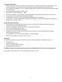
Definition of User Attention Words:
NOTE: Indicates information that is necessary for proper instrument operation
CAUTION: Indicates a potentially hazardous situation which, if not avoided, may result in minor or moderate injury.
It may also be used to alert against unsafe practices.
WARNING Indicates a potentially hazardous situation which, if not avoided, may result in death or in serious injury.
1
Introduction
The DynaChip™ Processor is designed for the automated performance of multiplex tests in the DynaChip™ strip,
which are standard 8-well strips with a protein array chip integrated in the bottom of each well.
Up to 12 DynaChip™ strips can be placed into the DynaChip™ Processor for the parallel multi parameter testing of up
to 96 individual samples. The DynaChip™ Processor itself is a liquid handling machine with an integrated detection
unit, performing all liquid handling and incubation steps of an assay including array image detection and analysis.
Automated device control and array image analysis is done via the DynaChip™ software installed on an external
computer connected to the DynaChip™ Processor.
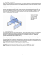
1.1
System Overview
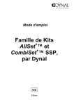
Fig. 1: Overview DynaChip™ Processor and Computer
3
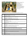
1.2
DynaChip™ Processor Components
8
7
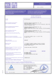
Sample plate (1), Array-Strip Frame
with DynaChip™ strips (2),
Tip Racks (3a&b),
Reagent Reservoir Racks with
Reagent Bottles (4a&b),
Liquid Handling Head (5),
Incubation Unit (not used in this
instrument version) (6), and Reading
Position (7), Wash Fountain (not in
use in this instrument version)(8),
Tip Waste bag (9).
Fig. 2: Detailed insight view of all DynaChip™ Processor components, for specifications see table below.
position
name & function
2
ArrayStrip Frame
- Aluminium microplate frame for insertion of DynaChip™ strip.
- Capacity: 1-12 DynaChip™ strip
- Note: Use only ArrayStrip frame provided with the Processor.
1
3
4
5
6
7
8
9
Sample plate
- Position of Sample plate containing all samples
- Capacity: 1-96 samples
Tip Racks
- Racks 3a and 3b containing DynaChip™ Processor pipetting tips.
- Cat#889.01D
- Capacity: up to 96 tips/rack
- When processing 1-11 strips load one rack in position 1, if processing a full 12 strip run, a second
rack is required.
- Note: Use only specified tips with the DynaChip™ Processor
Reagent Reservoir Racks
- Two racks at positions 4a and 4b each for the insertion of up to 6 reservoir bottles for reagent
solutions.
- Capacity: 2 x 6 containments for bottles of 20 ml nominal volume
- Note: position 4a allows cooling of the inserted rack.
- Note: Insert only reservoir bottles provided by Supplier.
Liquid Handling Head
- Central Liquid Handling Head for all dispensing, aspirating, and pipetting steps.
- The unit is connected to external wash buffer reservoir and to a waste container.
Incubation Unit
- Not in use
Reading Position
- Position for serial array image acquisition at the end of each test.
Wash Fountain
- Not in use.
Tip Waste
- Container for used tips.
4
1.3
Schematic Overview of main DynaChip™ Processor Component Positions
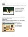
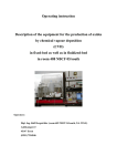
1.4 Liquid Handling Head
The Liquid Handling Head consists of the wash unit combined with separate Pipetting parts enabling to run two
different modes of liquid handling during test processing (fig. 3):
1 Pipetting (5a):
2 Wash (5b):
5b
Dispensing and aspirating of defined liquid volumes up to 250 µl from reagent reservoirs
(4a&b) or from Sample Plate into DynaChip™ strip wells (2). This part picks up pipette tips
out of the tip racks (3a&b). Used tips will be discarded into the waste bag (9). (This part also
moves the DynaChip™ ArrayStrip Frame into position for reading (7).)
Washing of chips with liquids from external buffer utilising the aspirating- and dispensing
channels during defined time intervals. The washing buffer is dispensed from the external
wash container. The removed liquid is discarded into external waste container with aspirator
channel.
Fig.3: Liquid Handling Head:
Wash part (5b) allows
simultaneous aspirating and
dispensing of solutions
Pipetting part (5a) runs
pipetting steps.
5a
5
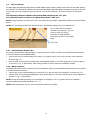
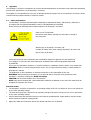
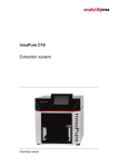
1.5 Additional DynaChip™ Processor functions
For several DynaChip™ Processor processing steps, the Sample Plate needs to be moved in XY-directions: during
these steps, the Pipetting part of the Liquid Handling Head (Fig.2, 5a) (without applied tip) is docking into the
magnetic holder of the ArrayStrip Frame (figure below) enabling the XY-movement for the following functions:
For array image detection at the end of a test, each well of the ArrayStrip Frame is moved into reading position
((7) see Fig. 2).
a)
b)
Adapter for insertion of
the Pipetting part (5a)
enabling the movement
of the ArrayStrip Frame
in XY- direction along
the tracks.
Well reading position.
Fig. 4: The ArrayStrip frame can be moved in XY direction for moving into reading position.
2
2.1
Installation
Instrument Unpacking & Setup
Unpacking
To unpack the DynaChip™ Processor instrument, the transportation box needs to be in an upright position to
open. The DynaChip™ Processor instrument needs at least 600 mm x 800 mm space and a safe and stable
standing position at bench level. (CAUTION! Heavy weight of approx. 30 kg!) The DynaChip™ Processor lid
swings upwards, when opened, the height is 970mm from the instrument base to the top of the lid.
Carefully lift and place the DynaChip™ Processor in position. (CAUTION! Heavy weight of approx. 30 kg!)
Inspect for any obvious signs of damage and report any damage immediately.
Ensure free ventilation of the instrument. The ventilation slots on side and bottom walls must not be covered.
Before any further installation of instrument and computer, ensure that the surrounding temperature is ambient.
Allow temperature equilibration for at least 6 hours in order to avoid condensation collecting within the
instrument.
Check level of cooling liquid. If necessary, top up cooling liquid (see paragraph 4.2).
For transportation, the instrument is secured with transportation interlocks. Open lid and secure it with the
provided fixing notches.
6
Carefully remove interlocks as described in the following figure:
Carefully unplug red rubber
interlock positioned at the top of
the Liquid Handling Head.
Remove red styrofoam blocks.
Fig. 5: DynaChip™ Processor after delivery with transportation interlocks.
In case the DynaChip™ Processor needs to be shipped back, please insert the interlocks before moving the
instrument. During transportation avoid any strong impacts, which may lead to alteration of both Liquid Handling
Head and Optical Unit position.
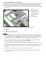
Connecting Tubing and Electricity
All electrical and tubing connectors are situated at the rear of the instrument (Fig.6).
Fig. 6: rear view of DynaChip™ Processor with power connector and ON/OFF switch (a), Camera Cable
connector (b), RS232 Cable connector (c), connection for Cooling Unit of Reagent Reservoir Rack (d)
and Power Connector for Cooling Unit of Reagent Reservoir Rack (e), input/output connectors for
Waste and external Buffer Reservoir tubing (f).
7
Connect the provided power supply cable with the instrument's line connector at the rear (a, Fig. 5) and plug it
into a power socket. Ensure that your voltage corresponds to the operating voltage of 85-230 V (AC) at 50-60 Hz,
which is required for the DynaChip™ Processor.
WARNING! The instrument must only be connected to power sockets with an operating voltage of 85-230 V (AC)
at 50-60 Hz!
To run the Cooling Unit for the Reagent Reservoir 4a of the instrument, a second power supply is required. Insert
plug fixed of Power Connector (e, Fig. 5) into the appropriate connector of the instrument (d, Fig. 5), then
connect this unit with a second power supply cable into power socket.
WARNING! The power supply for the Cooling Unit must be connected only to power sockets with an operating
voltage of 90-264 V (AC) at 47-63 Hz!
Place computer next to the DynaChip™ Processor instrument. Connect appropriate power supply cable of
computer with the related line connectors and plug them into a power socket.
For communication between DynaChip™ Processor and computer, plug both camera cable (b, Fig. 6 or Fig.7) and
serial cable (c, Fig. 6 or Fig 7) into the appropriate port inlets of DynaChip™ Processor instrument. Plug these
cables into appropriate connectors of the computer.
Fig. 7: plug in camera cable
('camera' adapter) and serial
control cable ('COM' adapter).
2.2
Rack Installations
For delivery, the rack holding Sample Plate and Tip Racks and the two Reagent Reservoir Racks are removed and
packed separately. These need to be placed into the DynaChip™ Processor after transportation (see Fig.8 below)
Fig. 8: View into DynaChip™
Processor after removal of
transportation interlocks with
installed ArrayStrip Frame (2) and
Incubator Unit (6). At the rear part,
the positions for the Reagent
Reservoir Racks (4) can be seen,
in the front part the metal pins for
anchoring the Sample Plate and
Tip Rack.
Metal pins
8
2.2.1
Rack holding Sample Plate and Tip Racks
Unpack tray holding Sample Plate and Tip Racks and fix onto the 8 metal pins for mounting. Insert the tray with its
movable clamps facing the front side of the DynaChip™ Processor (see fig. 9). The clamps enable the secure fixing of
the Tip Racks, which is necessary during processing.
Fig. 9: At the front mount the tray
holding Sample Plate and Tip Racks
onto metal pins and ensure that
the movable clamps are facing the
front of the instrument.
movable clamps
Loading of the tray with one or two Tip Racks can be done inside or outside of the DynaChip™ Processor (see also
paragraph 3.2). For loading, open clamps and insert Tip Racks. Close the clamps to fix the racks securely into place,
which is necessary during processing.
2.2.2
Reservoir Racks
Unpack both Reagent Reservoir Racks and place them in their appropriate positions 4a&b (see also figs. 2 & 8).
Make sure these are placed correctly the notched corners of the racks need to face the rear of the instrument.
Fig. 10: Inserted reagent Reservoir
Racks (here already containing
reservoir bottles); ensure correct
positioning marked by notched
corners of the racks.
Notched corners must face the rear
of DynaChip™ Processor
Attach frame for waste bags for pipette tips on front side of DynaChip™ Processor and insert waste bag.
Fig. 11: Fix frame for waste bags
at two slots installed at left front
side of the station.
9
2.3
Tube Connecting
For dispensing and aspirating steps with the Liquid Handling Head, liquid is transferred to and from this head utilising
two channels. The channels are linked to the external Buffer Bottle and Waste Bottle via tubing connected to the three
ports at the rear of the instrument (Fig.6 (f) and Fig. 12). For the DynaChip™ processor only port In1 and Out is
used.
The dispensing channel is linked to the external Buffer Bottle by the “In1” port.
The aspirating channel is linked to the Waste Bottle by the “OUT” port
NOTE: During operation, the waste port "OUT" must always be connected by appropriate tubing to an external Waste
Bottle.
NOTE: Only use tubing provided with the instrument or specified according to the list in appendix 5.4.
Fig. 12: Rear side of DynaChip™
Processor (see also fig. 6 (f)) with
ports In1 (and In2) for the
connection of external Buffer.
Bottle and port OUT for the Waste
Bottle.
"OUT" port
2.3.1 External Buffer Bottles 1 & 2
For rinsing and wash steps requiring higher or repeated volumes of buffer or water, the Liquid Handling Head needs
to be connected the external Buffer Bottles:
Connect one end of provided tubing to the Inlet-1 (In1) and/or Inlet-2 (In2) on the rear side of the DynaChip™
Processor (fig. 12).
Connect other end of tubing into appropriate external Buffer Bottle(s). The bottle should have a volume capacity
of at least 1 l (e.g. 1 l glass bottle). Place tubing in Bottle to ensure continuous availability of liquid.
2.3.2 Waste Container
To dissipate the liquids of the DynaChip™ Processor aspiration steps, the Liquid Handling Head needs to be connected
to an external Waste container.
Connect one end of provided tubing to the outlet (OUT) on the rear side of the DynaChip™ Processor (fig. 12).
Connect other end of tubing into appropriate empty waste bottle (s). The bottle should have a volume capacity of
at least 1 l (e.g. 1 l glass bottle). .
NOTE: During automated processing of 12 ArrayStrips (96 samples) in one run, typical volumes of DynaChip™
Processor aspirated and discarded liquid is 0.5 - 1 l.
NOTE: Before beginning a new run, ensure that waste container is emptied.
10
2.4
DynaChip™ Processor Lid
Always close Lid before starting any processing program. Close Lid before launching the controlling software from the
DynaChip™ Software, because after launch, the Liquid Handling Head will move as part of an initialisation procedure.
ATTENTION! Risk of Injury!
CAUTION! Do not open Lid during DynaChip™ Processor run! An alarm will sound if lid are opened during a run.
Should the Lid be opened during test procedure, all mechanical steps will automatically be interrupted, which may
lead to incorrect testing and test results. If the Lid is closed within 5 minutes (300 seconds) of opening the run will
continue, if not the run are aborted. For loading of DynaChip™ Processor, the opened Lid can be fixed into the
grooves on the upper frame of the instrument.
Fig. 13: Lid Illustration
shows how the opened
Lid can be fixed into
the grooves on the
upper frame of the
instrument
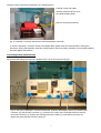
2.5
Communication Test
The communication test is part of the DynaChip™ Processor module in the DynaChip™ software. The communication
test is performed when the user launches the processor. Before launching the processor ensure that the Lid is
closed (Fig. 1) and that the green LED light at the front part of the DynaChip™ Processor is lit, indicating the
instrument has power and is ready for operation (Fig. 15).
If there are no communication between the computer and instrument then a dialog box will be displayed giving the
options: Abort, retry or ignore.
Once communication test is completed an automated hardware calibration process will start during which the Liquid
Handling Head moves into several defined XY-positions for adjustment. After calibration is completed, the unit moves
into its starting position at the right hand side rear corner of the XY-stage.
NOTE: Start DynaChip™ Software only after switching on DynaChip™ Processor.
CAUTION! To immediately abort the DynaChip™ Processor, push the red STOP button. (Fig 15)
NOTE: The STOP button should only be used for emergency stops; this is not the power button.
11
Fig. 14: Liquid Handling Head in
Start position after finishing
initialisation procedure.
Fig. 15: Green LED light shining after switching power ON,
The Red STOP button for immediate abortion of the DynaChip™ Processor program
12
3
3.1
Preparations
Tube Rinsing
If the user fail to wash the tubing and the machine was subsequently left for more than 24 hours a rinse procedure
should be carried out as described in the section 4.1
3.2
Tip Racks and Tip Waste Bag
Fill Tip Racks with the number of pipette tips required for the next run to be carried out. Loading of Tip Racks can be
performed inside or outside the instrument. Load one racks onto the DynaChip™ Processor by opening the securing
clamps or ‘gates’ of the rack at front of machine and sliding them into place. Close the securing clamps/gates – there
should be an audible sound as they shut. If processing 1-11 strips only one rack is required in position 3a. For a full
12 strip run, a second rack should be placed in position 3b
For information on tips for the DynaChip™ Processor, please refer to paragraph 5.3 of the appendix.
NOTE: Load tip racks only with new, unspoiled tips.
3.3
Cooling Unit
If cooling of the Reagent Reservoir Rack at position 4a is required, start Cooling Unit at least 15 min before adding
any reagent bottle or starting a test run. Switch on the Cooling Unit at the rear of the instrument (see Fig.5 e). A
green LED on the power supply of the unit indicates its status.
4
4.1
DynaChip™ Processor Maintenance
Tube Rinsing
Daily rinsing
Daily rinsing of all DynaChip™ Processor tubing is required for reliable test runs. First step of the script that performs
the runs fills all tubing and channels with appropriate buffer. Tubing should be washed if the machine will not be used
in the following 24 hours. Washing can also be carried out from the main screen of the Processor module – choose
the Instrument button:
During this pre-test procedure, tubing and channels are rinsed with the appropriate assay buffer provided in one
of the external Buffer Bottles. The Wash unit (5b) of Liquid Handling Head is positioned above the right of two
rear position in the Reagent Reservoir Rack (4b) to dispense and collect wash buffer.
NOTE: Ensure that one empty reservoir bottles have been placed into both rear positions of rack 4b!
After completion of the day’s experiments and if the machine will not be used in the following 24 hours select the
button that display “wash tubing”. The software give instruction with what to do: Make sure that the wash bottle
is filled with water. The wash procedure can also be started from the service section of the software
(see software manual). Ensure that all tubings are properly inserted into the appropriate bottles.
-and/or
After completion of the rinsing procedure, remove tubing from Wash Buffer Bottles and start wash
procedure 'dry' without the application of any buffer to allow the system to dry.
NOTE: The tubing entering waste container must stay inside the container to collect remaining liquids.
(For rinsing after longer periods of a non operating DynaChip™ Processor or before changing assays, see also
paragraph 5.1.)
13
4.2
Cooling System
The DynaChip™ Processor is provided with a separate Cooling System enabling the cooling of the Reagent Reservoir
at position 4a.
Cooling Fluid
The cooling system, generally, does not require any maintenance. However, the level of the cooling fluid needs to be
checked regularly. In case the level inside the filler neck is below 5 mm, additional cooling fluid needs to be added as
described in the figure below.
Fig.20: For filling the cooling fluid, remove
black plug of the filler neck protruding from
the cooling unit (see also fig. 6). Carefully fill
with fluid using a syringe or pipette, until 3/4
of the visible part of the filler neck is full.
Add fluid slowly to avoid foam formation.
After finishing, close neck with plug.
NOTE: Please use only cooling fluid specified by Supplier.
4.3
Cleaning of Detection Window
Check detection window regularly for contamination with liquid or dust particles. For reliable array imaging, the
window must be free of any lint or liquid film. Carefully clean soiled window using a soft cloth and water. Avoid
touching the window with any sharp edged object.
4.4
Replacing Fuses
If replacement of one or more fuses is required, use only fuses of the type and rating specified in appendix 6.3.
The fuses are situated close to the power plug next to the red ON/OFF switch. To replace fuses, open black lidded
plate, remove old fuses and carefully insert new ones.
ATTENTION: Before opening lidded plate and replacing fuses, disconnect power supply!
Fig. 21: Push back spring of fuse
holder by applying a small
screwdriver. Holder and fuse will
then be automatically released and
can be removed for replacing with
new fuse.
14
5
Trouble shooting
If you encounter difficulties with the ASP instrument, the following trouble shooting list may help to resolve them.
If a solution could not be found, the gained information from these observations will help qualified service engineers
to specify the appeared failure function and to solve the problem properly.
Error Description
ASP does not start.
After turning ON ASP instrument,
green status LED is not ON.
No communication between the
computer and instrument
Solution
Ensure, that instrument and control computer are properly connected and
turned ON.
Check, if green status LED on the front part is ON. If not, fuses might
have to be replaced (refer to paragraph 4.4).
Ensure, that instrument are properly connected and turned ON.
Check fuses. If necessary, replace them (refer to paragraph 4.4).
A dialog box will be displayed giving the options: Abort, retry or ignore.
(If the user select ignore the software can be used independently of the
processor, this is used for accessing the archive.)
Ensure, that instrument and control computer are properly connected and
turned ON.
Check, if green status LED on the front part is ON. If not, fuses might
have to be replaced (refer to paragraph 4.4).
Test run was aborted.
Ensure that cover has not been opened during test run. This will lead to
test abortion.
In all other cases, note error code and message and contact customer
service for further support.
Test run was aborted by accidental Restart ASP instrument. After its initialisation procedure, only a new test
pushing the red emergency
run can be started.
No results
Inappropriate liquid volume, ensure the user follow the DynaChip™ IFU.
In all other cases as listed below, contact Technical Service for further
support.
No transfer of liquid by pipetting part during dispensing steps.
No transfer of liquid or transfer of insufficient amounts of liquid during
dispensing steps.
No aspiration of liquid during aspirating steps.
No cooling of reagent reservoir
rack 4a.
Failure of analysis
Pipettor Unit does not work properly or cannot pick up pipette tips.
Control, if cooling unit was turned ON: green status LED of its power
supply must be ON.
Check for correct level of cooling fluid. If required, insert cooling fluid
(refer to paragraph 4.2).
If image in software shows developed markers on only part of the chip or
general precipitated substrate then failure may be due to inappropriate
wash buffer volume. Ensure the user follow the DynaChip™ IFU.
15
6
Appendix
The DynaChip™ Processor is designed to be used in laboratories/laboratory environment. Only trained and authorised
personnel are permitted to use the DynaChip™ Processor.
The Supplier is not responsible for any injury or damage caused by improper use of the DynaChip™ Processor. Please
read the following chapter carefully to avoid any misuse.
6.1 Safety Information:
- The DynaChip™ Processor was developed considering EU standards EN 55011, EN 61000-6-2, EN 61010-1.
It complies with the following standards of the EU: 89/336/EWG and 73/23/EWG
- Please observe the following caution labels located on the DynaChip™ Processor:
Plate at rear of instrument:
Disconnect mains before opening any closed part or casing of
the instrument.
Warning sign on DynaChip™ Processor Lid:
Consider all safety notes, when opening DynaChip™ Processor Lid.
Risk of injury by bruising.
-
-
Load instrument only with components and consumables specified in appendix 5.3 and specified by
your Supplier. Do not insert any other plates than ArrayStrip Frame and microtitreplates authorised
by SUPPLIER.
Do not use any flammable, explosive, or corrosive material in combination with the device or its components.
WARNING: Device is working using electrical current. Do not open instrument casing or modify outside of
descriptions in manual
The application of other hazardous or infectious material is in full responsibility of the user.
WARNING: During instrument operation, do not open Lid and do not perform any operations inside
DynaChip™ Processor working area. RISK of bruising!
CAUTION: Do not touch incubator unit. Hot surfaces!
NOTE: Only devices cleared with a decontamination certificate as attached on the end of this manual will be
accepted for inspection and service.
Electrical Power
The DynaChip™ Processor is licensed for an operating voltage of 85-230 V at 50/60 Hz. Do not run instrument
at any other operating voltage!
The external Cooling Unit is licensed for an operating voltage of 90-264 V at 47/63 Hz. Do not run instrument
at any other operating voltage!
Connect instrument and external Cooling Unit only with the provided power supply cables to a power socket
with a protective conductor (earth/ground).
Apply only cables and connectors without any defect and which are not twisted.
16
The right Environment
Before unpacking the reader, ensure that the temperature of the reader has reached room temperature in order
to avoid condensation collecting within the reader. Allow temperature equilibration for at least 6 hours.
The instrument was designed for use in a laboratory environment. Keep free of dust, harsh and explosive solvents
and acidic vapours.
Protect the instrument against humidity > 85%.
Avoid direct sunlight and vibration.
Ensure free ventilation of the instrument. The ventilation slots on side and bottom walls must not be covered.
It is not allowed to use device within explosive atmosphere.
The DynaChip™ Processor needs a safe and stable standing position at bench level.
The DynaChip™ Processor Workstation is designed to work properly only if the surrounding room temperature is
between 15° - 35°C (59° - 95°F).
Important Operation Notes
Do not open any of the closed parts of the instrument or the casing. Any damage resulting from improper
use will result in the loss of Warranty rights.
Avoid any contamination of the Optical Unit of the instrument with liquids.
Do not move ArrayStrip Frame by hand.
Load only new unspoiled/unused pipette tips.
If DynaChip™ Processor is not in use, always keep the lid closed to prevent dust particles from collecting
inside the optical components.
For transportation use only the original DynaChip™ Processor wrapping.
Please turn off DynaChip™ Processor, when not in use.
Warnings
To avoid any damage and injury, the DynaChip™ Processor must be switched off immediately in case of:
abnormal noises
smoke or the smell of fire
if the power supply cable is damaged
if liquid entered the instrument.
Immediate switch-off is performed by pushing the red STOP bottom on the front of the instrument.
Please inform the customer service, if any of these incidents have occurred.
17
6.2
Technical Details
DynaChip™ Processor
Components
Liquid Handling Head
Incubation Unit
XY-Unit with separate DynaChip™ Processor Aspirator and
Dispenser channel and Pipetting part
thermoelectric heating
Camera Interface
Computer Interface
camera SUB-D, 15-pole
RS232 C, SUB-D 9-pole
Detection Unit, pixel resolution
Computer
Processor
752 x582
Disk Space
160 GB IDE
Operating System
MS Windows XP Pro
RAM
Environmental
at least 512 MB
Operating Temperature (OT)
Incubator Temperature
15° - 35°C (59° - 95°F)
OT - 70°C (OT - 158°F)
Storage Temperature
-10°- 50°C
Cooling Unit, minimum temperature
Relative Humidity
Sunlight
Method of Disposal
Usage
Altitude
Power DynaChip™ Processor
Supply
Consumption
10°C
no relative humidity leading to condensation within device
No direct sunlight
at the responsibility of the Supplier’s customer
commercial
up to 2000 m
85 - 230 V (AC), 50 - 60 Hz
Fuses
375 W / T10A
Delay fuse 5x20 mm 10 A
Supply
100 - 240 V (AC), 47 - 63 Hz
Dimensions
width x depth x height: 588 x 770 x 563 mm
height with opened lid: 970 mm
approx. 30 kg
Power Cooling Unit
Consumption
Physical
Weight
65 W max
18
6.3
Accessories and Disposables
Accessory
DynaChip™ Processor
Reservoir Bottles
DynaChips
Sample Plates
Specifications
Supplier
8 well strips for inserting into
ArrayStrip Frame
96 well microplates, tested and
authorised by Supplier
SUPPLIER
20 ml nominal volume
Only bottles provided by Supplier
DynaChip™ Processor Pipetting
Tips
250 µl nominal volume, capacity
of 96 tips/rack
Tubings for external Reservoirs
and Waste Container
Silicone tubing with
Ø1,6/Ø3,2mm inner/outer
diameter, 120 mm in length
cooling fluid based on propylene
glycol, 30%, with corrosion
inhibitor
Delay fuse 5x20 mm 10 A
Cooling Fluid
Fuses
6.4
NUNC, U96 PP-0.5 ml, catalogue-no.
267245
(please contact Supplier for plates from
other Suppliers)
CyBio AG, Germany,
cat. no. OL 2001-25-300
IVGN Cat #. 889.01D
Novodirect D71558
local Suppliers
local Suppliers
Warranty Disclaimer
SUPPLIER warrants that the supplied products meet the specifications contained in the technical data sheets and the
specifications stated in the manuals. SUPPLIER warrants that its products are of good quality and suitable for normal
use. SUPPLIER's obligation and the purchaser's exclusive remedy under this warranty is limited either to replacement,
at SUPPLIER's expense, of any products, which shall be defective in manufacture, and which shall be returned to
SUPPLIER, transportation prepaid, or at SUPPLIER's option, refund of the purchase price. Claims for merchandise
damaged in transit must be submitted to the carrier. This warranty shall not apply to any products, which shall have
been altered outside SUPPLIER, nor shall it apply to any products, which have been subjected to misuse or
mishandling. A Warranty for a period of one year is valid for all parts besides wear and tear parts and consumables.
ALL OTHER WARRANTIES, EXPRESSED, IMPLIED OR STATUTORY, ARE HEREBY SPECIFICALLY EXCLUDED. IN NO
EVENT SHALL SUPPLIER BE LIABLE FOR ANY SPECIAL, INCIDENTAL OR CONSEQUENTIAL DAMAGES.
19
Decontamination Certificate
Institute Name & Address
______________________________________
______________________________________
Instrument Serial No.
_____________________________________
This instrument has not been in contact with blood, other body fluids, or any infectious sample material.
It has not been used in an invasive procedure.
The instrument has been cleaned and decontaminated in preparation for inspection, service, or repair.
The decontamination procedure is as outlined below:
______________________________________________________
_____________________________________________________________________________
The instrument could be contaminated. The nature of risk and safety precautions to be adopted are as
follows:
______________________________________________________
______________________________________________________
______________________________________________________
Signed:_____________________________ Date:___________________
Position:_____________________________________________________
Address:____________________________________________________
Tel. No.:_________________________________
20
CONTACT DETAILS
For country-specific contact information visit our web site at
www.invitrogen.com
11 Bassendale Road, Croft Business Park,
Bromborough, Wirral, CH62 3QL, U.K.
Tel: +44 151 346 1234, Fax: +44 151 346 1223
e-mail: [email protected]
©
Copyright 2006 Dynal Biotech Ltd., U.K. All rights reserved
Printed: 010.08.06 Rev 000