1
User Manual
ADAM-5000 Series
I/O Modules
Copyright
The documentation and the software included with this product are copyrighted 2008
by Advantech Co., Ltd. All rights are reserved. Advantech Co., Ltd. reserves the right
to make improvements in the products described in this manual at any time without
notice. No part of this manual may be reproduced, copied, translated or transmitted
in any form or by any means without the prior written permission of Advantech Co.,
Ltd. Information provided in this manual is intended to be accurate and reliable. However, Advantech Co., Ltd. assumes no responsibility for its use, nor for any infringements of the rights of third parties, which may result from its use.
Acknowledgements
Intel and Pentium are trademarks of Intel Corporation.
Microsoft Windows and MS-DOS are registered trademarks of Microsoft Corp.
All other product names or trademarks are properties of their respective owners.
Product Warranty (2 years)
Advantech warrants to you, the original purchaser, that each of its products will be
free from defects in materials and workmanship for two years from the date of purchase.
This warranty does not apply to any products which have been repaired or altered by
persons other than repair personnel authorized by Advantech, or which have been
subject to misuse, abuse, accident or improper installation. Advantech assumes no
liability under the terms of this warranty as a consequence of such events.
Because of Advantech’s high quality-control standards and rigorous testing, most of
our customers never need to use our repair service. If an Advantech product is defective, it will be repaired or replaced at no charge during the warranty period. For outof-warranty repairs, you will be billed according to the cost of replacement materials,
service time and freight. Please consult your dealer for more details.
If you think you have a defective product, follow these steps:
1. Collect all the information about the problem encountered. (For example, CPU
speed, Advantech products used, other hardware and software used, etc.) Note
anything abnormal and list any onscreen messages you get when the problem
occurs.
2. Call your dealer and describe the problem. Please have your manual, product,
and any helpful information readily available.
3. If your product is diagnosed as defective, obtain an RMA (return merchandize
authorization) number from your dealer. This allows us to process your return
more quickly.
4. Carefully pack the defective product, a fully-completed Repair and Replacement
Order Card and a photocopy proof of purchase date (such as your sales receipt)
in a shippable container. A product returned without proof of the purchase date
is not eligible for warranty service.
5. Write the RMA number visibly on the outside of the package and ship it prepaid
to your dealer.
Edition 2.14
Printed in Taiwan
ADAM-5000 Series User Manual
April 2014
ii
Declaration of Conformity
CE
This product has passed the CE test for environmental specifications when shielded
cables are used for external wiring. We recommend the use of shielded cables. This
kind of cable is available from Advantech. Please contact your local supplier for
ordering information.
FCC Class A
Note: This equipment has been tested and found to comply with the limits for a Class
A digital device, pursuant to part 15 of the FCC Rules. These limits are designed to
provide reasonable protection against harmful interference when the equipment is
operated in a commercial environment. This equipment generates, uses, and can
radiate radio frequency energy and, if not installed and used in accordance with the
instruction manual, may cause harmful interference to radio communications. Operation of this equipment in a residential area is likely to cause harmful interference in
which case the user will be required to correct the interference at his own expense.
FM
This equipment has passed the FM certification. According to the National Fire Protection Association, work sites are classified into different classes, divisions and
groups, based on hazard considerations. This equipment is compliant with the specifications of Class I, Division 2, Groups A, B, C and D indoor hazards.
Technical Support and Assistance
1.
2.
Visit the Advantech web site at www.advantech.com/support where you can find
the latest information about the product.
Contact your distributor, sales representative, or Advantech's customer service
center for technical support if you need additional assistance. Please have the
following information ready before you call:
– Product name and serial number
– Description of your peripheral attachments
– Description of your software (OS, version, application software, etc.)
– A complete description of the problem
– The exact wording of any error messages
Safety Precaution - Static Electricity
Follow these simple precautions to protect yourself from harm and the products from
damage.
To avoid electrical shock, always disconnect the power from your PC chassis
before you work on it. Don't touch any components on the CPU card or other
cards while the PC is on.
Disconnect power before making any configuration changes. The sudden rush of
power as you connect a jumper or install a card may damage sensitive electronic
components.
iii
ADAM-5000 Series User Manual
Safety Instructions
1.
2.
3.
Read these safety instructions carefully.
Keep this User Manual for later reference.
Disconnect this equipment from any AC outlet before cleaning. Use a damp
cloth. Do not use liquid or spray detergents for cleaning.
4. For plug-in equipment, the power outlet socket must be located near the equipment and must be easily accessible.
5. Keep this equipment away from humidity.
6. Put this equipment on a reliable surface during installation. Dropping it or letting
it fall may cause damage.
7. The openings on the enclosure are for air convection. Protect the equipment
from overheating. DO NOT COVER THE OPENINGS.
8. Make sure the voltage of the power source is correct before connecting the
equipment to the power outlet.
9. Position the power cord so that people cannot step on it. Do not place anything
over the power cord.
10. All cautions and warnings on the equipment should be noted.
11. If the equipment is not used for a long time, disconnect it from the power source
to avoid damage by transient overvoltage.
12. Never pour any liquid into an opening. This may cause fire or electrical shock.
13. Never open the equipment. For safety reasons, the equipment should be
opened only by qualified service personnel.
14. If one of the following situations arises, get the equipment checked by service
personnel:
15. The power cord or plug is damaged.
16. Liquid has penetrated into the equipment.
17. The equipment has been exposed to moisture.
18. The equipment does not work well, or you cannot get it to work according to the
user's manual.
19. The equipment has been dropped and damaged.
20. The equipment has obvious signs of breakage.
21. DO NOT LEAVE THIS EQUIPMENT IN AN ENVIRONMENT WHERE THE
STORAGE TEMPERATURE MAY GO BELOW -20° C (-4° F) OR ABOVE 60° C
(140° F). THIS COULD DAMAGE THE EQUIPMENT. THE EQUIPMENT
SHOULD BE IN A CONTROLLED ENVIRONMENT.
22. CAUTION: DANGER OF EXPLOSION IF BATTERY IS INCORRECTLY
REPLACED. REPLACE ONLY WITH THE SAME OR EQUIVALENT TYPE
RECOMMENDED BY THE MANUFACTURER, DISCARD USED BATTERIES
ACCORDING TO THE MANUFACTURER'S INSTRUCTIONS.
23. The sound pressure level at the operator's position according to IEC 704-1:1982
is no more than 70 dB (A).
DISCLAIMER: This set of instructions is given according to IEC 704-1. Advantech
disclaims all responsibility for the accuracy of any statements contained herein.
ADAM-5000 Series User Manual
iv
Chapter
1
Overview...............................................1
1.1
Introduction ............................................................................................... 2
Table 1.1: Supported I/O Module List.......................................... 2
Analog Input Modules ............................................................................... 3
1.2.1 ADAM-5013 3-ch RTD Input Module ............................................ 3
Figure 1.1 ADAM-5013 Module Front View ................................. 3
Figure 1.2 RTD Inputs ................................................................. 4
Table 1.2: Technical Specifications of ADAM-5013 .................... 4
Figure 1.3 Applying Calibration Resistance................................. 5
Table 1.3: Calibration Resistances of ADAM-5013 ..................... 5
1.2.2 ADAM-5017 8-ch Analog Input Module ........................................ 6
Figure 1.4 ADAM-5017 Module Front View ................................. 6
Figure 1.5 Millivolt and Volt Input................................................. 6
Figure 1.6 Process Current Input................................................. 7
Figure 1.7 Locations of Jumpers ................................................. 7
Table 1.4: Technical Specifications of ADAM-5017 .................... 7
1.2.3 ADAM-5017P 8-ch AI with independent Input .............................. 8
Figure 1.8 ADAM-5017P Module Front View............................... 8
Figure 1.9 Millivolt and Volt Input................................................. 8
Figure 1.10Process Current Input................................................. 8
Figure 1.11Locations of Jumpers ................................................. 9
Table 1.5: Technical Specifications of ADAM-5017P .................. 9
1.2.4 ADAM-5017H 8-ch High Speed Analog Input Module ................ 10
Figure 1.12ADAM-5017H Module Front View ............................ 10
Figure 1.13Millivolt and Volt Input............................................... 10
Figure 1.14Process Current Input............................................... 10
Figure 1.15Locations of Jumpers ............................................... 11
Table 1.6: Technical Specifications of ADAM-5017H................ 11
Table 1.7: ADAM-5017H Input Signal Ranges .......................... 12
1.2.5 ADAM-5017UH 8-ch Ultra High Speed Analog Input Module..... 13
Figure 1.16ADAM-5017UH Module Front View.......................... 13
Figure 1.17Millivolt and Volt Input............................................... 13
Figure 1.18Process Current Input............................................... 13
Figure 1.19Locations of RC Filter Jumper Setting...................... 14
Figure 1.20Locations of RC Filter Jumper Setting...................... 14
Table 1.8: Technical Specifications of ADAM-5017UH ............. 15
Table 1.9: ADAM-5017UH Input Sgnal Ranges ........................ 15
1.2.6 ADAM-5018 7-ch Thermocouple Input Module........................... 16
Figure 1.21ADAM-5018 Module Front View ............................... 16
Figure 1.22Thermocouple Input.................................................. 16
Table 1.10: Technical Specifications of ADAM-5018 .................. 17
1.2.7 ADAM-5018P 7-ch Thermocouple Input Module ........................ 17
Figure 1.23ADAM-5018P Module Front View............................. 17
Figure 1.24Thermocouple Input.................................................. 18
Table 1.11: Technical Specifications of ADAM-5018P ................ 18
1.2
Chapter
Chapter
2
Analog Output Modules ....................19
2.1
Analog Output Modules........................................................................... 20
2.1.1 ADAM-5024 4-ch Analog Output Module.................................... 20
Figure 2.1 ADAM-5024 Module Frontal View ............................ 20
Figure 2.2 Analog Output........................................................... 20
Table 2.1: Technical Specifications of ADAM-5024 .................. 21
3
Analog I/O Module Calibration .........23
3.1
Analog I/O Module Calibration ............................................................... 24
v
ADAM-5000 Series User Manual
3.1.1
3.1.2
Chapter
Chapter
ADAM-5000 Series Analog Input Module Calibration................. 24
Figure 3.1 Applying Calibration Voltage .................................... 24
Table 3.1: Calibration Voltage of ADAM-5017/5018 ................. 27
Table 3.2: Calibration Voltage (ADAM-5017H) ......................... 27
Table 3.3: Calibration Voltage of ADAM-5018P ........................ 28
Table 3.4: Calibration Voltage of ADAM-5017UH ..................... 28
Analog Output Module Calibration.............................................. 29
Figure 3.2 Output Module Calibration........................................ 29
4
Digital Input/Output Modules........... 31
4.1
Digital Input/Output Modules................................................................... 32
4.1.1 ADAM-5050 16-ch Universal Digital I/O Module......................... 32
Figure 4.1 DIP Switch Setting for Digital I/O Channel ............... 32
Figure 4.2 ADAM-5050 Module Frontal View ............................ 32
Figure 4.3 Dry Contact Signal Input (ADAM-5050) ................... 33
Figure 4.4 Wet Contact Signal Input (ADAM-5050)................... 33
Figure 4.5 Digital Output with SSR (ADAM-5050/5056)............ 33
Table 4.1: Technical Specifications of ADAM-5050 .................. 34
4.1.2 ADAM-5051(D) 16-ch Digital Input Module ................................ 34
Figure 4.6 ADAM-5051 Module Frontal View ............................ 34
Figure 4.7 TTL Input (ADAM-5051/5051D) ............................... 35
Figure 4.8 Contact Closure Input (ADAM-5051/5051D) ............ 35
Table 4.2: Technical Specifications of ADAM-5051/5051D....... 36
4.1.3 ADAM-5051S 16-ch Isolated Digital Input Module with LED ...... 36
Figure 4.9 ADAM-5051S Module Front View ............................ 36
Figure 4.10ADAM-5051S Module Wiring Diagram..................... 37
Table 4.3: Technical Specifications of ADAM-5051S................ 37
4.1.4 ADAM-5052 8-ch Isolated Digital Input Module.......................... 38
Figure 4.11ADAM-5052 Module Front View............................... 38
Figure 4.12Isolation Digital Input (ADAM-5052) ......................... 38
Table 4.4: Technical Specifications of ADAM-5052 .................. 38
4.1.5 ADAM-5053S 32-ch Isolated Digital Input Module ..................... 39
Figure 4.13ADAM-5053S Module Front View ............................ 39
Figure 4.14ADAM-5053S Module Wiring Diagram..................... 39
Table 4.5: ADAM-5053S Technical Specifications.................... 39
4.1.6 ADAM-5055S 16-ch Isolated Digital I/O Module with LED ......... 40
Figure 4.15ADAM-5055S Module Front View ............................ 40
Figure 4.16ADAM-5055S Module Wiring Diagram..................... 40
Table 4.6: Technical Specifications of ADAM-5055S................ 41
4.1.7 ADAM-5056(D) 16-ch Digital Output Module w/LED .................. 41
Figure 4.17ADAM-5056 Module Frontal View ............................ 41
Figure 4.18Digital Output with SSR (ADAM-5050/5056)............ 42
Table 4.7: Technical Specifications of ADAM-5056 .................. 42
4.1.8 ADAM-5056S 16-ch Isolated Digital Output Module with LED ... 43
Figure 4.19ADAM-5056S Module Front View ............................ 43
Figure 4.20ADAM-5056S Module Wiring Diagram..................... 44
Table 4.8: Technical Specifications of ADAM-5056S................ 44
4.1.9 ADAM-5056SO 16-ch Isolated Digital Output Module with LED 44
Figure 4.21ADAM-5056SO Module Front View.......................... 45
Figure 4.22ADAM-5056SO Module Wiring Diagram .................. 46
Table 4.9: Technical Specifications of ADAM-5056SO ............. 46
4.1.10 ADAM-5057S 32-ch Isolated Digital Output Module................... 47
Figure 4.23ADAM-5057S Module Front View ............................ 47
Figure 4.24ADAM-5057S Module Wiring Diagram..................... 47
Table 4.10: ADAM-5057S Technical Specification...................... 47
5
Relay Output Modules ...................... 49
ADAM-5000 Series User Manual
vi
Chapter
Chapter
5.1
Relay Output Modules............................................................................. 50
5.1.1 ADAM-5060 Relay Output Module.............................................. 50
Figure 5.1 ADAM-5060 Module Frontal View ............................ 50
Figure 5.2 Relay Output............................................................. 50
Table 5.1: Technical Specifications of ADAM-5060 .................. 50
5.1.2 ADAM-5069 Relay Output Module.............................................. 51
Figure 5.3 ADAM-5069 Module Front View Wiring.................... 51
6
Counter/Frequency Modules ............53
6.1
Counter/Frequency Modules................................................................... 54
6.1.1 ADAM-5080 4-ch Counter/Frequency Module............................ 54
Figure 6.1 ADAM-5080 Module ................................................. 55
Figure 6.2 Isolated Input Level .................................................. 55
Figure 6.3 TTL Input Level......................................................... 55
Figure 6.4 Counter / Frequency Mode....................................... 56
Figure 6.5 Wiring for Up/Down Counting ................................... 57
Figure 6.6 Wiring for Bi-direction Counting................................ 57
Figure 6.7 Wiring for Frequency Mode ...................................... 58
Figure 6.8 Setting Alarm Limit ................................................... 58
Figure 6.9 Sending Alarm Signal (Recommended Settings) ..... 59
Figure 6.10Sending Alarm Signal (Not Recommended)............. 59
Figure 6.11Digital Output Mapping ............................................. 60
Figure 6.12Jumper Location on the ADAM-5080 Module........... 61
Figure 6.13TTL/Isolated Input Level Selection ........................... 61
Table 6.1: ADAM-5080 Technical Specifications ...................... 61
Figure 6.14 Counter / Frequency Mode...................................... 62
Figure 6.15Wiring for Up/Down Counting ................................... 63
Figure 6.16Wiring for Bi-direction Counting................................ 63
Figure 6.17Wiring for Frequency Mode ...................................... 64
Figure 6.18Setting Alarm Limit ................................................... 64
Figure 6.19Sending Alarm Signal (Recommended Settings) ..... 65
Figure 6.20Sending Alarm Signal (Not Recommended)............. 65
Figure 6.21Digital Output Mapping ............................................. 66
Figure 6.22Jumper Location on the ADAM-5081 Module........... 67
Figure 6.23TTL/Isolated Input Level Select ................................ 67
Table 6.2: ADAM-5081 Technical Specifications ...................... 67
7
Serial Modules ...................................69
7.1
Serial Modules ........................................................................................ 70
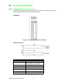
7.1.1 ADAM-5090 4-port RS-232 Communication Module .................. 70
Table 7.1: Baud Rate Settings................................................... 70
Figure 7.1 ADAM-5090 Module ................................................. 70
Figure 7.2 ADAM-5090 Application Wiring ................................ 71
Table 7.2: Pin Mapping.............................................................. 71
Table 7.3: ADAM-5090 Technical Specifications ...................... 71
Figure 7.3 Jumper Locations on the CPU Card......................... 72
Figure 7.4 Jumper Settings........................................................ 72
7.1.2 ADAM-5091 4-port RS-232 Communication Module .................. 75
Table 7.4: Baud Rate Settings................................................... 75
Figure 7.5 ADAM-5091 Module ................................................. 75
Figure 7.6 ADAM-5091 Application Wiring ................................ 76
Table 7.5: PIN Mapping............................................................. 76
Table 7.6: ADAM-5091 Technical Specifications ...................... 76
7.1.3 ADAM-5095 2-port CAN Serial Communication Module with
isolation protection (Only for ADAM-5560 Series) ...................... 77
Figure 7.7 ADAM-5095 Module ................................................. 77
Table 7.7: CAN Serial Port Pin Assignment (CAN1 ~ CAN2).... 78
vii
ADAM-5000 Series User Manual
Table 7.8: ADAM-5095 DTE Pin Wiring .................................... 79
Table 7.9: Maximum Bit rate vs. Bus Length............................. 79
Chapter
8
Storage Modules ............................... 81
8.1
Storage Modules..................................................................................... 82
8.1.1 ADAM-5030 2-slot SD Storage Module with 2x USB2.0 ............ 82
Figure 8.1 ADAM-5030 Module Frontal View ............................ 82
Table 8.1: Technical Specifications of ADAM-5030 .................. 82
ADAM-5000 Series User Manual
viii
Chapter
1
Overview
1
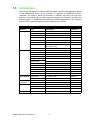
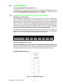
1.1 Introduction
This manual will discuss in detail the specifications, functions and application wiring
of the ADAM-5000 series of I/O modules. To organize an ADAM-5510 Series
Controller, you need to select I/O modules to interface the main unit with field
devices or processes that you have previously determined. Advantech provides the
following types of ADAM-5000 I/O modules for various applications so far. Following
table is the I/O modules support list we provided for user’s choice.
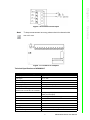
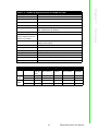
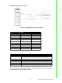
Table 1.1: Supported I/O Module List
Module
Name
Analog I/O
ADAM-5013
3-ch RTD input
Isolated
ADAM-5017
8-ch AI
Isolated
ADAM-5017P
8-ch AI with independent Input
Isolated
ADAM-5017H
8-ch High-speed AI
Isolated
ADAM-5017UH
8-ch Ultra High-speed AI
Isolated
ADAM-5018
7-ch Thermocouple input
Isolated
ADAM-5018P
7-ch Thermocouple input with
independent Input
Isolated
ADAM-5024
4-ch AO
Isolated
ADAM-5050
16-ch DI/O
Non-isolated
ADAM-5051
16-ch DI
Non-isolated
ADAM-5051D
16-ch DI w/LED
Non-isolated
ADAM-5051S
16-ch Isolated DI w/LED
Isolated
Digital I/O
Specification
Reference
ADAM-5052
8-ch DI
Isolated
ADAM-5053S
32-ch Isolated DI
Isolated
ADAM-5055S
16-ch. Isolated DI/O w/LED
Isolated
ADAM-5056
16-ch DO
Non-isolated
ADAM-5056D
16-ch DO w/LED
Non-isolated
ADAM-5056S
16-ch Isolated DO w/LED
Isolated
ADAM-5056SO
16-ch Iso. DO w/LED (source)
Isolated
ADAM-5057S
32-ch Isolated DO
Isolated
6-ch. Relay output
Isolated
8-ch Relay output
Isolated
Isolated
Relay Output ADAM-5060
ADAM-5069
Counter/
Frequency
ADAM-5080
4-ch Counter/Frequency
ADAM-5081
4-ch High Speed Counter/Frequency Isolated
Serial I/O
ADAM-5090
4-port RS232
Storage
Non-isolated
ADAM-5091
4-port RS232 with Share Interrupt
Non-isolated
ADAM-5095
2-port CAN
Isolated
ADAM-5030
2-slot SD Storage Module
Non-isolated
ADAM-5000 Series User Manual
2
Analog input modules use an A/D converter to convert sensor voltage, current, thermocouple or RTD signals into digital data. The digital data is then translated into engineering units. The analog input modules protect your equipment from ground loops
and power surges by providing opto-isolation of the A/D input and transformer
based isolation up to 3,000 VDC.
Chapter 1
1.2 Analog Input Modules
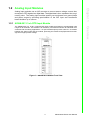
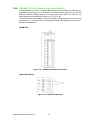
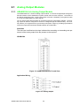
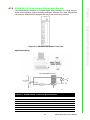
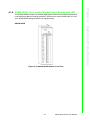
1.2.1 ADAM-5013 3-ch RTD Input Module
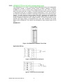
Figure 1.1 ADAM-5013 Module Front View
3
ADAM-5000 Series User Manual
Overview
The ADAM-5013 is a 16-bit, 3-channel RTD input module that features programmable input
ranges on all channels. This module is an extremely cost-effective solution for industrial measurement and monitoring applications. Its opto-isolated inputs provide 3,000 VDC of isolation
between the analog input and the module, protecting the module and peripherals from damage due to high input line voltage.
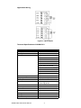
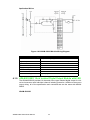
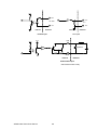
Application Wiring
Figure 1.2 RTD Inputs
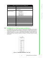
Technical Specifications of ADAM-5013
Table 1.2: Technical Specifications of ADAM-5013
Analog input channels
3
Input type
Pt or Ni
RTD
RTD type and temperature range Pt -100 to 100°C a=0.00385
Pt 0 to 100°C a=0.00385
Pt 0 to 200°C a=0.00385
Pt 0 to 600°C a=0.00385
Pt -100 to 100°C a=0.00392
Pt 0 to 100°C a=0.00392
Pt 0 to 200°C a=0.00392
Pt 0 to 600°C a=0.00392
Ni -80 to 100°C
Ni 0 to 100°C
Isolation voltage
3000 VDC
Sampling rate
10 samples/sec (total)
Input impedance
2 M
Bandwidth
13.1 Hz @ 50 Hz
15.72 Hz @ 60 Hz
Input connections
2, 3 or 4 wire
Accuracy
± 0.1% or better
Zero drift
± 0.015°C/°C
Span drift
± 0.01°C/°C
CMR@50/60 Hz
150 dB
NMR@50/60 Hz
100 dB
Power consumption
1.2 W
ADAM-5000 Series User Manual
4
4.
First, with the correct zero (offset) calibration resistance connected as shown
above, issue a Zero Calibration command to the module using the Calibrate
option in the ADAM utility software.
Second, with the correct span resistance connected as shown above, issue a
Span Calibration command to the module using the Calibrate option in the ADAM
utility software. Note that the module zero calibration must be completed prior to
the span calibration.
5.
Note!
If the above procedure is ineffective, the user must first issue an RTD
Self Calibration command $aaSi2 to the module and then complete
steps 4 and 5 after self calibration is complete.
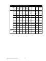
Table 1.3: Calibration Resistances of ADAM-5013
Input Range
Code (Hex)
Input Range
Span Calibration Zero Calibration
Resistance
Resistance
20
Pt, -100 to 100°C A = 0.00385
140 Ohms
60 Ohms
21
Pt, 0 to 100°C A = 0.00385
140 Ohms
60 Ohms
22
Pt, 0 to 200°C A = 0.00385
200 Ohms
60 Ohms
23
Pt, 0 to 600°C A = 0.00385
440 Ohms
60 Ohms
24
Pt, -100 to 100°C A = 0.003916
140 Ohms
60 Ohms
25
Pt, 0 to 100°C A = 0.003916
140 Ohms
60 Ohms
26
Pt, 0 to 200°C A = 0.003916
200 Ohms
60 Ohms
27
Pt, 0 to 600°C A = 0.003916
440 Ohms
60 Ohms
28
Ni, -80 to 100° C
200 Ohms
60 Ohms
29
Ni, 0 to 100°C
200 Ohms
60 Ohms
5
ADAM-5000 Series User Manual
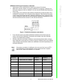
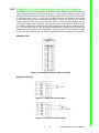
Overview
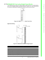
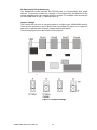
Figure 1.3 Applying Calibration Resistance
Chapter 1
ADAM-5013 RTD Input Resistance Calibration
1. Apply power to the module and let it warm up for about 30 minutes.
2. Make sure that the module is correctly installed and is properly configured for
the input range you want to calibrate. You can use the ADAM utility software to
help in this.
3. Connect the correct reference self resistance between the screw terminals of the
ADAM-5013 as shown in the following wiring diagram. Table 2 below shows the
correct values of the span and zero calibration resistances to be connected. Reference resistances used can be from a precision resistance decade box or from
discrete resistors with the values 60, 140, 200 and 440 ohms.
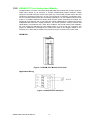
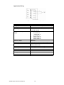
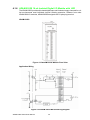
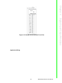
1.2.2 ADAM-5017 8-ch Analog Input Module
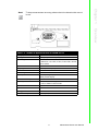
The ADAM-5017 is a 16-bit, 8-channel analog differential input module that provides programmable input ranges on all channels. It accepts millivolt inputs (±150mV, ±500mV), voltage
inputs (±1V, ±5V and ±10V) and current input (±20 mA). The module provides data to the host
computer in engineering units (mV, V or mA). This module is an extremely cost-effective solution for industrial measurement and monitoring applications. Its opto-isolated inputs provide
3,000 VDC of isolation between the analog input and the module, protecting the module and
peripherals from damage due to high input line voltage. Additionally, the module uses analog
multiplexers with active over- voltage protection. The active protection circuitry assures that
signal fidelity is maintained even under fault conditions that would destroy other multiplexers. This module can withstand an input voltage surge of 70 Vp-p with ±15 V supplies. The
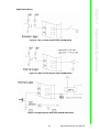
jumpers of ADAM-5017 are designed for current input. Refer to the diagram below for the
locations (JP1). Short the pin-head by the jumpers to set the channel to be current mode.
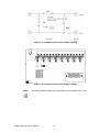
ADAM-5017
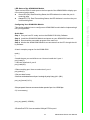
Figure 1.4 ADAM-5017 Module Front View
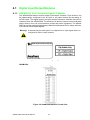
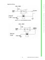
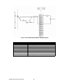
Application Wiring
Figure 1.5 Millivolt and Volt Input
ADAM-5000 Series User Manual
6
Chapter 1
Note!
To keep measurement accuracy please short the channels that
are not in use.
Figure 1.7 Locations of Jumpers
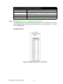
Technical Specifications of ADAM-5017
Table 1.4: Technical Specifications of ADAM-5017
Analog Input Channels
Eight differential
Input Type
mV, V, mA
Input Range
± 150 mV, ± 500 mV, ± 1 V, ± 5 V, ± 10 V and ± 20 mA
Isolation Voltage
3000 VDC
Sampling Rate
10 samples/sec (total)
Analog Input Signal Limit
15 V max.
Max. allowable voltage difference
between two connectors in a module
15 V max.
Input Impedance
2M (voltage input)
120 (current input)
Bandwidth
13.1 Hz @ 50 Hz, 15.72 Hz @ 60 Hz
Accuracy
± 0.1% or better
Zero Drift
± 1.5 µV/°C
Span Drift
± 25 PPM/°C
CMR @ 50/60 Hz
92 dB min.
Power Requirements
+ 10 to + 30 VDC (non-regulated)
Power Consumption
1.2 W
7
ADAM-5000 Series User Manual
Overview
Figure 1.6 Process Current Input
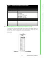
1.2.3 ADAM-5017P 8-ch AI with independent Input
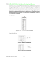
The ADAM-5017P is a 16-bit, 8-channel analog differential input and independent
configuration module. It accepts millivolt inputs (±150mV, ±500mV, 0~150mV,
0~500mV, 0~1V, 0~5V, 0~10V, 0~15V), voltage inputs (±1V, ±5V, ±10V, and ±20V)
and current input (±20 mA, 4~20mA). The module provides data to the host computer
in engineering units (mV, V (supports uni-poloar and bipolar) or mA). This module is
an extremely cost-effective solution for industrial measurement and monitoring applications. Its high common mode provides 200 VDC, protecting the module and
peripherals from damage due to high input line voltage. Additionally, the module uses
analog multiplexers with active over-voltage protection. The active protection circuitry
assures that signal fidelity is maintained even under fault conditions that would
destroy other multiplexers. This module can withstand an input voltage surge of ±60
VDC.
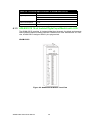
ADAM-5017P
Figure 1.8 ADAM-5017P Module Front View
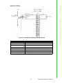
Application Wiring
Figure 1.9 Millivolt and Volt Input
Figure 1.10 Process Current Input
ADAM-5000 Series User Manual
8
To keep measurement accuracy please short the channels that are not
in use.
Chapter 1
Note!
Overview
Figure 1.11 Locations of Jumpers
Table 1.5: Technical Specifications of ADAM-5017P
Analog Input Channels
Eight differential and independent
Input Type
mV, V (uni-polar and bipolar), mA
Input Range
± 150 mV, ± 500 mV, ± 1 V, ± 5 V, ± 10 V, 0~150mV,
0~500mV, 0~1V, 0~5V, 0~10V, 0~15V and ± 20 mA,
and 4~20mA
High common mode
200 VDC
Sampling Rate
10 samples/sec (total)
Resolution
16 bits
Over Voltage
±60 VDC
Input Impedance
800K (voltage input)
120 (current input)
Built-in TVS/ESD protection
Yes
Accuracy
± 0.1% or better Voltage mode
± 0.2% or better Current mode
Zero Drift
± 6 µV/°C
Span Drift
± 25 PPM/°C
CMR @ 50/60 Hz
92 dB min.
Power Consumption
1.25 W (Max)
9
ADAM-5000 Series User Manual
1.2.4 ADAM-5017H 8-ch High Speed Analog Input Module
ADAM-5017H is an 8-ch analog differential input module that provides programmable
input ranges on each channel. The module provides data to the host microprocessor
in engineering units (mV, V or mA) or two’s complement format. Its sampling rate
depends on the data format received: up to 100 Hz (total). Each input channel has
3000 VDC of optical isolation between the outside analog input line and the module,
protecting the module and peripherals from high input line voltages. Additionally, the
module uses analog multiplexers with active over-voltage protection. The active protection circuitry assures that signal fidelity is maintained even under fault conditions
that would destroy other multiplexers. The analog inputs can withstand a constant 70
Vp-p input with ±15V supplies.
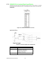
ADAM-5017H
Figure 1.12 ADAM-5017H Module Front View
Application Wiring
Figure 1.13 Millivolt and Volt Input
Figure 1.14 Process Current Input
ADAM-5000 Series User Manual
10
Chapter 1
Note!
To maintain measurement accuracy pleases short channels not in use.
Table 1.6: Technical Specifications of ADAM-5017H
Analog Input Channels
8 differential
ADC Resolution
12 bits, plus sign bit
Type of ADC
Successive approximation
Isolation Voltage
3000 VDC
Sampling Rate
100 Hz
Input Impedance
2M (voltage input)
120 (current input)
Signal Input Bandwidth
1000 Hz for both voltage inputs and current inputs
Analog Signal Range
±15 V max.
Analog Signal Range for
any two measured Pins
±15 V max.
Power Requirements
+10 to +30 VDC (non-regulated)
Power Consumption
1.8 W
Accuracy
± 0.1% or better
11
ADAM-5000 Series User Manual
Overview
Figure 1.15 Locations of Jumpers
Table 1.7: ADAM-5017H Input Signal Ranges
Input
Range
Voltage 0 ~ 10 V
Inputs
With
Overranging
Offset
Offset Gain
Error @ Error @ Error
25°C
-10 to
@ 25°C
+70°C
Gain Error Offset Drift Gain
@ -10
Drift
To
+70°C
Display
Resolution
0 ~ 11 V ±1 LSB
±2 LSB ±1 LSB ±2 LSB
17 µV/°C
50 ppm/ 2.7 mV
°C
0~5V
0 ~ 5.5 V ±1 LSB
±2 LSB ±1.5
LSB
±2 LSB
16 µV/°C
50 ppm/ 1.3 mV
°C
0 ~ 2.5 V
0 ~ 2.75 ±1 LSB
V
±2 LSB ±1.5
LSB
±2 LSB
20 µV/°C
55 ppm/ 0.67 mV
°C
0~1V
0~
±1 LSB
1.375 V
±2.5
LSB
±2 LSB ±2.5 LSB 20 µV/°C
60 ppm/ 0.34 mV
°C
0 ~ 500
mV
0~
687.5
mV
-
±5 LSB ±3 LSB ±3.5 LSB 20 µV/°C
67 ppm/ 0.16 mV
°C
± 10 V
±11 V
±1 LSB
±2 LSB ±1 LSB ±2 LSB
17 µV/°C
50 ppm/ 2.7 mV
°C
±5V
±0 ~ 5.5 ±1 LSB
V
±2 LSB ±1.5
LSB
±2 LSB
17 µV/°C
50 ppm/ 1.3 mV
°C
± 2.5 V
±0 ~
2.75 V
±2 LSB ±1.5
LSB
±2 LSB
20 µV/°C
55 ppm/ 0.67 mV
°C
±1V
±0 ~
±1 LSB
1.375 V
±2 LSB ±2.5 LSB 20 µV/°C
60 ppm/ 0.34 mV
°C
-
±5 LSB ±3 LSB ±3.5 LSB 20 µV/°C
67 ppm/ 0.16 mV
°C
Current 0 ~ 20 mA 22 mA
Inputs
±1 LSB
±1 LSB ±1.5
LSB
±2 LSB
nA/°C
ppm/°C 5.3 µ
4 ~ 20 mA 22 mA
±1 LSB
±1 LSB ±1.5
LSB
±2 LSB
nA/°C
ppm/°C 5.3 µ
± 500 mV ±0 ~
687.5
mV
ADAM-5000 Series User Manual
±1 LSB
±2.5
LSB
12
ADAM-5017UH
Figure 1.16 ADAM-5017UH Module Front View
Application Wiring
Figure 1.17 Millivolt and Volt Input
Figure 1.18 Process Current Input
13
ADAM-5000 Series User Manual
Overview
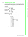
The ADAM-5017UH is a 12-bit plus sign bit, 8-channel analog differential input module that provides programmable input ranges on each channel. It accepts voltage inputs (±10 V and 0-10 V)
and current inputs (0-20 mA and 4-20 mA). The module provides data to the host microprocessor
in engineering units (mV, V or mA) or two’s complement format. Its sampling rate depends
on the data format received: up to 200k Hz (total). Space is reserved for 125-ohm, 0.1%, 10 ppm
resistors (See Figure 9). Each input channel has 3000 VDC of optical isolation between the outside analog input line and the module, protecting the module and peripherals from high input
line voltages. Additionally, the module uses analog multiplexers with active overvoltage protection. The active protection circuitry assures that signal fidelity is maintained even under fault
conditions that would destroy other multiplexers. The analog inputs can withstand a constant
70 Vp-p input with ±15V supplies. The jumpers of ADAM-5017UH are designed for current input.
Chapter 1
1.2.5 ADAM-5017UH 8-ch Ultra High Speed Analog Input Module
Figure 1.19 Locations of RC Filter Jumper Setting
Figure 1.20 Locations of RC Filter Jumper Setting
Note!
To maintain measurement accuracy please short channels not in use.
ADAM-5000 Series User Manual
14
Chapter 1
Table 1.8: Technical Specifications of ADAM-5017UH
Eight differential
Resolution
12 bits
Input Type
mV, V, mA
Input Range
+0~10V , ± 10 V , +4~20mA and ± 20 mA
Isolation Voltage
3000 VDC
Sampling Rate
200k samples/sec (single channel)
50k samples/sec (8 channel)
Analog Input Signal Limit
15 V max.
Overview
Analog Input Channels
Max. allowable voltage dif- 15 V max.
ference between two connectors in a module
Input Impedance
2M (voltage input)
120 (current input)
Bandwidth
200kHz
Accuracy
± 0.1% or better
Low or high pass filter
Configured by User
CMR @ 50/60 Hz
92 dB min.
Power Requirements
+ 10 to + 30 VDC (non-regulated)
Power Consumption
1.75 W (typical ); 2.2W (max)
Signal Input Bandwidth
200kHz for both voltage and current inputs
Table 1.9: ADAM-5017UH Input Sgnal Ranges
Input Range Offset
Error @
25°C
Offset Error @
-10 to +70°C
Gain Error Gain Error @
@ 25°C
-10 to +70°C
Display
Resolution
Voltage 0 ~ 10 V
Inputs
± 10 V
±1 LSB
±2 LSB
±1 LSB
±2 LSB
2.7 mV
±1 LSB
±2 LSB
±1 LSB
±2 LSB
2.7 mV
Current 0 ~ 20 mA
Inputs
4 ~ 20 mA
±1 LSB
±1 LSB
±1.5 LSB
±2 LSB
5.3 µ
±1 LSB
±1 LSB
±1.5 LSB
±2 LSB
5.3 µ
15
ADAM-5000 Series User Manual
1.2.6 ADAM-5018 7-ch Thermocouple Input Module
The ADAM-5018 is a 16-bit, 7-channel thermocouple input module that features programmable input ranges on all channels. It accepts millivolt inputs (±15 mV, ±50 mV,
±100 mV, ±500 mV), voltage inputs (±1 V, ±2.5 V), current input (±20 mA, requires 125
ohms resistor) and thermocouple input (J, K, T, R, S, E, B).
The module forwards the data to the host computer in engineering units (mV, V, mA or
temperature °C). An external CJC on the plug-in terminal is designed for accurate temperature measurement.
ADAM-5018
Figure 1.21 ADAM-5018 Module Front View
Application Wiring
Figure 1.22 Thermocouple Input
ADAM-5000 Series User Manual
16
Analog Input Channels
Seven differential
Input Type
mV, V, mA, Thermocouple
Input Range
± 15 mV, ± 50 mV, ± 100 mV, ± 500 mV, ± 1 V, ± 2.5
V and ± 20 mA
T/C Type and
Temperature Range
J
K
T
E
R
S
B
Isolation Voltage
3000 VDC
Sampling Rate
10 samples/sec (total)
Overview
0 to 760 °C
0 to 1370 °C
-100 to 400 °C
0 to 1400 °C
500 to 1750 °C
500 to 1750 °C
500 to 1800 °C
Input Impedance
2M
Bandwidth
13.1 Hz @ 50 Hz, 15.72 Hz @ 60 Hz
Accuracy
± 0.1% or better
Zero Drift
± 0.3 µV/°C
Span Drift
± 25 PPM/°C
CMR @ 50/60 Hz
92 dB min.
Power Consumption
1.2 W
1.2.7 ADAM-5018P 7-ch Thermocouple Input Module
The ADAM-5018P is a 16-bit, 8-channel Thermocouple Independent input module
that provides programmable input ranges on all channels. It accepts Various Thermocouple inputs (Type J, K, T, E, R, S, B) and provides data to the host computer in
engineering units (oC) In order to satisfy various temperature requirements in one
module, each analog channel is allowed to configure an individual range for several
applications.
Figure 1.23 ADAM-5018P Module Front View
17
Chapter 1
Table 1.10: Technical Specifications of ADAM-5018
ADAM-5000 Series User Manual
Application Wiring
Figure 1.24 Thermocouple Input
Table 1.11: Technical Specifications of ADAM-5018P
Analog Input Channels
Seven differential & independent thermocouple
Input Type
mV, V, mA, Thermocouple
Input Range
± 15 mV, ± 50 mV, ± 100 mV, ± 500 mV, ± 1 V, ±
2.5 V and ± 20 mA
T/C Type and Temperature
Range
J
K
T
E
R
S
B
Isolation Voltage
3000 VDC
Sampling Rate
10 samples/sec (Selected by Utility)
Input Impedance
2M (voltage input)
120 (current input)
Bandwidth
13.1 Hz @ 50 Hz, 15.72 Hz @ 60 Hz
Accuracy
± 0.1% or better
Zero Drift
± 6 µV/°C
Span Drift
± 25 PPM/°C
CMR @ 50/60 Hz
92 dB min.
Power Consumption
0.5 W
ADAM-5000 Series User Manual
0 to 760 °C
0 to 1370 °C
-100 to 400 °C
0 to 1400 °C
500 to 1750 °C
500 to 1750 °C
500 to 1800 °C
18
Chapter
2
Analog Output
Modules
2
2.1 Analog Output Modules
2.1.1 ADAM-5024 4-ch Analog Output Module
The ADAM-5024 is a 4-channel analog output module. It receives its digital input through the
RS-485 interface of the ADAM-5510 system module from the host computer. The format of
the data is engineering units. It then uses the D/A converter controlled by the system module
to convert the digital data into output signals.
You can specify slew rates and start up currents through the configuration software. The analog output can also be configured as current or voltage through the software utility. The module protects your equipment from ground loops and power surges by providing opto-isolation
of the D/A output and transformer based isolation up to 3000 VDC.
Slew Rate
The slew rate is defined as the slope indicated the ascending or descending rate per
second of the analog output from the present to the required.
ADAM-5024
Figure 2.1 ADAM-5024 Module Frontal View
Application Wiring
Figure 2.2 Analog Output
ADAM-5000 Series User Manual
20
Table 2.1: Technical Specifications of ADAM-5024
Four
Output Type
V, mA
Output Range
0-20mA, 4-20mA, 0-10V
Isolation Voltage
3000 Vdc
Output Impedance
0.5 Ohms
Accuracy
±0.1% of FSR for current output ±0.2% of FSR for voltage
output
Zero Drift
Voltage output: ±30 µV/ºC Current output: ±0.2 µA/ºC
Resolution
±0.015% of FSR
Span Temperature Coefficient ±25 PPM/ºC
Programmable Output Slope* 0.125-128.0 mA/sec 0.0625-64.0 V/sec
Current Load Resistor
0-500 Ohms (source)
Power Consumption
2.5W (Max.)
* This function is only for the ADAM-5000/485 and ADAM-5000E
21
ADAM-5000 Series User Manual
Analog Output Modules
Analog Output Channels
Chapter 2
Technical Specifications of ADAM-5024
ADAM-5000 Series User Manual
22
Chapter
3
3
Analog I/O Module
Calibration
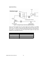
3.1
Analog I/O Module Calibration
Analog input/output modules are calibrated when you receive them. However, calibration is sometimes required. No screwdriver is necessary because calibration is done
in software with calibration parameters stored in the ADAM-5000 analog I/O module‘s
onboard EEPROM. The ADAM-5000 system comes with the ADAM utility software
that supports calibration of analog input and analog output. Besides the calibration
that is carried out through software, the modules incorporate automatic Zero Calibration and automatic Span Calibration at boot up or reset.
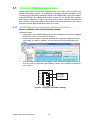
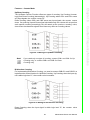
3.1.1 ADAM-5000 Series Analog Input Module Calibration
Modules: ADAM-5017, 5017P, 5017H, 5017UH, 5018, and 5018P
Calibration Steps:
1. Apply power to the ADAM-5000 system that the analog input module is plugged
into and let it warm up for about 30 minutes.
2. Ensure that the module is correctly installed and is properly configured for the
input range you want to calibrate. You can do this with the ADAM utility software.
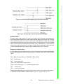
3.
Use a precision voltage source to apply a span calibration voltage to the module's V0+ and V0- terminals. (See Tables 5-2 and 5-3 for reference voltages for
each range.)
1
V0+
Voltage
Source
V0V1+
V1-
Figure 3.1 Applying Calibration Voltage
ADAM-5000 Series User Manual
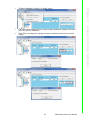
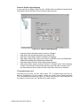
24
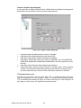
”Enable Calibration Function” in “Setup” menu.
5.
Use a precision voltage source to apply a span calibration voltage to the module's V0+ and V0- terminals.
Click "Zero" and apply the voltage as pop out windows to the Ch-0 and click
"Apply."
25
ADAM-5000 Series User Manual
Analog I/O Module Calibration
6.
Chapter 3
4.
7.
Click “Span” and apply the voltage as pop out windows to the Ch-0 and click
“Apply.”
Note!
Zero calibration and span calibration must be completed before CJC
calibration. To calibrate CJC, the thermocouple attached to ADAM-5018
and a standard thermometer should be used to measure a standard
known temperature, such as the freezing point of pure water. The
amount of offset between the ADAM-5018 and the standard thermometer is then used in the ADAM utility to complete CJC calibration.
ADAM-5000 Series User Manual
26
Module Input Range Input Range
Code (Hex)
Span Calibration
Voltage
5018
±15 mV
+15 mV
01h
±50 mV
+50 mV
02h
±100 mV
+100 mV
03h
±500 mV
+500 mV
04h
±1 mV
+1 V
05h
±2.5 V
+2.5 V
06h
±20 mV
+20 mA (1)
0Eh
J thermocouple 0 to 1370°C
+50 mV
0Fh
K thermocouple 0 to 1370°C
+50 mV
10h
T thermocouple -100 to 400°C
+22 mV
11h
E thermocouple 0 to 1000°C
+80 mV
12h
R thermocouple 500 to 1750°C +22 mV
13h
S thermocouple 500 to 1800°C
+22 mV
14h
B thermocouple 500 to 1800°C
+152 mV
07h
Not used
08h
ºC ±10 V
+10 V
09h
±5 V
+5 V
0Ah
±1 V
+1 V
0Bh
±500 mV
+500 mV
0Ch
±150 mV
+150 mV
0Dh
±20 mA
+20 mV (1)
Table 3.2: Calibration Voltage (ADAM-5017H)
Module
5017H
Note!
Input Range
Code (Hex)
Input Range
Span Calibration
Voltage
00h
±10 V
+10 V
01h
0 ~ 10 V
+10 V
02h
±5 V
+5 V
03h
0~5V
+5 V
04h
±2.5 V
+2.5 V
05h
0 ~ 2.5 V
+2.5 V
06h
±1 V
+1 V
07h
0~1V
+1 V
08h
±500 mV
+500 mV
09h
0 ~ 500 mV
+500 mV
0ah
4 ~ 20 mA
*(1)
0bh
0 ~ 20 mA
*(1)
You can substitute 2.5 V for 20 mA if you remove the current conversion
resistor for that channel. However, the calibration accuracy will be limited to 0.1% due to the resistor's tolerance.
27
ADAM-5000 Series User Manual
Analog I/O Module Calibration
5017
00h
Chapter 3
Table 3.1: Calibration Voltage of ADAM-5017/5018
Table 3.3: Calibration Voltage of ADAM-5018P
Module Input Range
Code (Hex)
Input Range
Span Calibration
Voltage
5018P
00h
±15 mV
+15 mV
01h
±50 mV
+50 mV
02h
±100 mV
+100 mV
03h
±500 mV
+500 mV
04h
±1 mV
+1 V
05h
±2.5 V
+2.5 V
06h
±20 mV
+20 mA (1)
07h
4 ~ 20 mA
+16 mA (1)
0Eh
J thermocouple 0 to 1370°C
+50 mV
0Fh
K thermocouple 0 to 1370°C
+50 mV
10h
T thermocouple -100 to 400°C
+22 mV
11h
E thermocouple 0 to 1000°C
+80 mV
12h
R thermocouple 500 to 1750°C
+22 mV
13h
S thermocouple 500 to 1800°C
+22 mV
14h
B thermocouple 500 to 1800°C
+152 mV
Table 3.4: Calibration Voltage of ADAM-5017UH
Module
Input Range Code Input Range
(Hex)
Span Calibration
Voltage
5017H
08h
±10 V
+10 V
48h
0 ~ 10 V
+10 V
46h
0 ~ 20 mA
*(1)
07h
4 ~ 20 mA
*(1)
Note!
You can substitute 2.5 V for 20 mA if you remove the current conversion
resistor for that channel. However, the calibration accuracy will be limited to 0.1% due to the resistor's tolerance.
ADAM-5000 Series User Manual
28
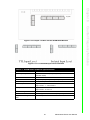
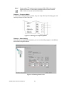
4.
Connect either a 5-digit mA meter or voltmeter with a shunt resistor (250 ohms,
.01 % and 10 ppm) to the screw terminals of the module.
Figure 3.2 Output Module Calibration
5.
6.
Issue the Analog Data Out command to the module with an output value of 4
mA.
Check the actual output value at the modules terminals. If this does not equal 4
mA, use the "Trim" option in the "Calibrate" submenu to change the actual output. Trim the module until the mA meter indicates exactly 4 mA, or in case of a
voltage meter with shunt resistor, the meter indicates exactly 1 V. (When calibrating
for 20 mA using a voltage meter and shunt resistor, the correct voltage should
be 5 V.)
29
ADAM-5000 Series User Manual
Analog I/O Module Calibration
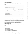
The output current of analog output modules can be calibrated by using a low calibration value and a high calibration value. The analog output modules can be configured
for one of two ranges: 0-20 mA and 4-20 mA. Since the low limit of the 0-20 mA range (0
mA) is internally an absolute reference (no power or immeasurably small power), just
two levels are needed for calibration: 4 mA and 20 mA.
1. Set the ADAM-5000 system to be INITIAL Mode then apply power to the system
including the analog output module for about 30 minutes.
2. Ensure that the module is correctly installed and is properly configured for the
range you want to calibrate. You can do this by using the ADAM utility software.
3. Before execute the calibration process in the utility, enable the calibration function by checking [Setup -> Allow Calibration ]
Chapter 3
3.1.2 Analog Output Module Calibration
7.
Issue the 4 mA Calibration command to indicate that the output is calibrated
and to store the calibration parameters in the module's EEPROM.
8. Execute an Analog Data Out command with an output value of 20 mA. The
module's output will be approximately 20 mA.
9. Execute the Trim Calibration command as often as necessary until the output current is equal to exactly 20 mA.
10. Execute the 20 mA Calibration command to indicate that the present output is
exactly 20 mA. The analog output module will store its calibration parameters
in the unit's EEPROM.
ADAM-5000 Series User Manual
30
Chapter
4
4
Digital Input/Output
Modules
4.1 Digital Input/Output Modules
4.1.1 ADAM-5050 16-ch Universal Digital I/O Module
The ADAM-5050 features sixteen digital input/output channels. Each channel can
be independently configured to be an input or an output channel by the setting of
its DIP switch. The digital outputs are open collector transistor switches that can be
controlled from the ADAM-5000. The switches can also be used to control solid-state
relays, which in turn can control heaters, pumps and power equipment. The ADAM5000 can use the module’s digital inputs to determine the state of limit or safety switches,
or to receive remote digital signals.
Warning! A channel may be destroyed if it is subjected to an input signal while it is
configured to be an output channel.
Figure 4.1 DIP Switch Setting for Digital I/O Channel
ADAM-5050
Figure 4.2 ADAM-5050 Module Frontal View
ADAM-5000 Series User Manual
32
Chapter 4
Application Wiring
Figure 4.4 Wet Contact Signal Input (ADAM-5050)
Figure 4.5 Digital Output with SSR (ADAM-5050/5056)
33
ADAM-5000 Series User Manual
Digital Input/Output Modules
Figure 4.3 Dry Contact Signal Input (ADAM-5050)
Table 4.1: Technical Specifications of ADAM-5050
Points
16
Channel Setting
Bitwise selectable by DIP switch
Digital Input
Dry Contact Logic Level 0: close to GND Logic Level 1: open
Wet Contact Logic Level 0: +2 V max Logic Level 1: +4 V to 30 V
Digital Output
Open collector to 30 V, 100mA max load
Power Dissipation
450 mW
Power Consumption
0.4 W
4.1.2 ADAM-5051(D) 16-ch Digital Input Module
The ADAM-5051 provides sixteen digital input channels. The ADAM-5510 can use the
module’s digital inputs to determine the state of limit or safety switches or to receive
remote digital signals.
ADAM-5051/5051D
Figure 4.6 ADAM-5051 Module Frontal View
ADAM-5000 Series User Manual
34
Chapter 4
Application Wiring
Figure 4.8 Contact Closure Input (ADAM-5051/5051D)
35
ADAM-5000 Series User Manual
Digital Input/Output Modules
Figure 4.7 TTL Input (ADAM-5051/5051D)
Table 4.2: Technical Specifications of ADAM-5051/5051D
Points
16
Digital Input
Logic level 0: + 1 V max
Logic level 1: + 3.5 to 30 V Pull up current: 0.5 mA
10 k- resistor to + 5 V
Power Consumption
0.3 W
Indicator
ADAM-5051D only
4.1.3 ADAM-5051S 16-ch Isolated Digital Input Module with LED
The ADAM-5051S provides 16 isolated digital input channels for critical environments
need individual channel isolating protection. Different from other ADAM-5000 I/O modules, ADAM-5051S designed with 21 pins plug terminal.
ADAM-5051S
Figure 4.9 ADAM-5051S Module Front View
ADAM-5000 Series User Manual
36
Chapter 4
Application Wiring
Table 4.3: Technical Specifications of ADAM-5051S
Point
16 (4-channel/group)
Digital Input
Logic Level 0: + 3 V max Logic Level 1: + 10 to 50 V
Optical Isolation
2500 VDC
Opto-isolator response time
25 µs
Over-voltage Protection
70 VDC
Power Consumption
0.8 W
LED Indicator
On when active
I/O Connector Type
21-pin plug-terminal
37
ADAM-5000 Series User Manual
Digital Input/Output Modules
Figure 4.10 ADAM-5051S Module Wiring Diagram
4.1.4 ADAM-5052 8-ch Isolated Digital Input Module
ADAM-5052 provides eight fully independent isolated channels. All have 5000 VRMS isolation
to prevent ground loop effects and to pre- vent damage from power surges on the input lines.
ADAM-5052
Figure 4.11 ADAM-5052 Module Front View
Application Wiring
Figure 4.12 Isolation Digital Input (ADAM-5052)
Table 4.4: Technical Specifications of ADAM-5052
Points
8 Differential
Digital input
Logic level 0: + 1 V max
Logic level 1: + 3.5 to 30 V
Isolation voltage: 5000 V RMS
Resistance: 3 k-/ 0.5 W
Power consumption
0.4 W
ADAM-5000 Series User Manual
38
The ADAM-5053S provides 32 isolated digital input channels for critical environments need individual channel isolating protection. Different from other ADAM-5000
I/O modules, ADAM-5053S designed with 40-pin flat cable wiring terminal.
Application Wiring
Figure 4.14 ADAM-5053S Module Wiring Diagram
Table 4.5: ADAM-5053S Technical Specifications
Point
32
Digital Input
Logic Level 0: + 5 V max Logic Level 1: 19 to 35 V
Optical Isolation
2500 VDC
Opto-isolator response time
25 µs
Over-voltage Protection
35 VDC
Power Consumption
1 W (max.)
I/O Connector Type
40-pin flat cable wiring terminal
39
ADAM-5000 Series User Manual
Digital Input/Output Modules
Figure 4.13 ADAM-5053S Module Front View
Chapter 4
4.1.5 ADAM-5053S 32-ch Isolated Digital Input Module
4.1.6 ADAM-5055S 16-ch Isolated Digital I/O Module with LED
The ADAM-5055S provides 8 isolated digital input and 8 isolated output channels for critical environments need individual channel isolating protection. Different from other
ADAM-5000 I/O modules, ADAM-5055S designed with 21 pins plug terminal.
ADAM-5055S
Figure 4.15 ADAM-5055S Module Front View
Application Wiring
Figure 4.16 ADAM-5055S Module Wiring Diagram
ADAM-5000 Series User Manual
40
16
Digital Output
8 (8-channel/group)
Open collector to 40 V
200 mA max load per channel
Optical Isolation
2500 VDC
Opto-isolator response time
25 µs
Supply Voltage
5 ~ 40 VDC
Digital Input
8 (4-ch/group)
Dry Contact
Logic Level 0: open
Logic Level 1: close to GND
Wet Contact
Logic Level 0: + 3 V max
Logic Level 1: + 10 to 50 V
Dry Contact & Wet contact
Selectable
Optical Isolation
2500 VDC
Opto-isolator response time
25 µs
Over-voltage Protect
70 VDC
Power Consumption
0.68 W
LED Indicator
On when active
I/O Connector Type
21-pin plug-terminal
4.1.7 ADAM-5056(D) 16-ch Digital Output Module w/LED
The ADAM-5056 features sixteen digital output channels. The digital outputs are
open-collector transistor switches that you can control from the ADAM-5000 main
unit. You also can use the switches to control solid-state relays.
ADAM-5056
Figure 4.17 ADAM-5056 Module Frontal View
41
ADAM-5000 Series User Manual
Digital Input/Output Modules
Points
Chapter 4
Table 4.6: Technical Specifications of ADAM-5055S
Application Wiring
Figure 4.18 Digital Output with SSR (ADAM-5050/5056)
There are 16-point digital input and 16-point digital output modules in the ADAM5000 series. The addition of these solid state digital I/O devices allows these modules to control or monitor the interfaces between high power DC or AC lines and TTL
logic signals. A command from the host converts these signals into logic levels
suitable for the solid-state I/O devices.
Table 4.7: Technical Specifications of ADAM-5056
Points
16
Digital Output
Open collector to 30 V 100 mA max load
Power Dissipation
450 mW
Power Consumption
0.25 W
ADAM-5000 Series User Manual
42
The ADAM-5056S provides 16 isolated digital output channels for critical environments
need individual channel isolating protection. Different from other ADAM-5000 I/O modules, ADAM-5056S designed with 21 pins plug terminal.
Chapter 4
4.1.8 ADAM-5056S 16-ch Isolated Digital Output Module with LED
ADAM-5056S
Digital Input/Output Modules
Figure 4.19 ADAM-5056S Module Front View
43
ADAM-5000 Series User Manual
Application Wiring
Figure 4.20 ADAM-5056S Module Wiring Diagram
Table 4.8: Technical Specifications of ADAM-5056S
Points
16 (8-channel/group)
Digital Output
Open collector to 40 V 200 mA max load per channel
Optical Isolation
2500 VDC
Opto-isolator response time
25 µs
Supply Voltage
5 ~ 40 VDC
Power consumption
0.6 W
LED Indicator
On when active
I/O Connector Type
21-pin plug-terminal
4.1.9 ADAM-5056SO 16-ch Isolated Digital Output Module with LED
The ADAM-5056SO provides 16 channels source type isolated digital output for critical environments need individual channel isolating protection. Addition to the source
output wiring, all of the specification and command sets are the same with ADAM5056S.
ADAM-5056SO
ADAM-5000 Series User Manual
44
Chapter 4
Application Wiring
45
ADAM-5000 Series User Manual
Digital Input/Output Modules
Figure 4.21 ADAM-5056SO Module Front View
Figure 4.22 ADAM-5056SO Module Wiring Diagram
Table 4.9: Technical Specifications of ADAM-5056SO
Points
16 (8-ch/group)
Digital Output
Open collector to 40 V 200 mA max load per channel
Optical Isolation
2500 VDC
Opto-isolator response time
25 us
Supply Voltage
5 ~ 40 VDC
Power consumption
0.6 W
LED Indicator
On when active
I/O Connector Type
21-pin plug-terminal
ADAM-5000 Series User Manual
46
The ADAM-5057S provides 32 isolated digital output channels for critical environments need individual channel isolating protection. Different from other ADAM-5000
I/O modules, ADAM-5057S designed with 40-pin flat cable wiring terminal.
Application Wiring
Figure 4.24 ADAM-5057S Module Wiring Diagram
Table 4.10: ADAM-5057S Technical Specification
Points
32
Digital Output
Contact with ADAM-3920R
Optical Isolation
2500 VDC
Contact Rating
10 A 250VAC, 10 A 30VDC
Power Input
+24 VDC
Power consumption
1 W (max.)
Relay Type
SPST (Form A)
I/O Connector Type
40-pin flat cable wiring terminal
47
ADAM-5000 Series User Manual
Digital Input/Output Modules
Figure 4.23 ADAM-5057S Module Front View
Chapter 4
4.1.10 ADAM-5057S 32-ch Isolated Digital Output Module
ADAM-5000 Series User Manual
48
Chapter
5
5
Relay Output Modules
5.1 Relay Output Modules
5.1.1 ADAM-5060 Relay Output Module
The ADAM-5060 relay output module is a low-cost alternative to SSR modules. It provides 6 relay channels, two of Form A and four of Form C.
ADAM-5060
Figure 5.1 ADAM-5060 Module Frontal View
Application Wiring
Figure 5.2 Relay Output
Table 5.1: Technical Specifications of ADAM-5060
Points
6, two Form A and four Form C
Contact rating
AC: 125 V @ 0.6A; 250 V @ 0.3 A
DC: 30 V @ 2 A; 110 V @ 0.6 A
Breakdown voltage
500 VAC(50/60 Hz)
Relay on time (typical)
3 ms
Relay off time (typical)
1 ms
Total switching time
10 ms
Insulation resistance
1000 M- min. @ 500 VDC
Power consumption
0.7 W
ADAM-5000 Series User Manual
50
The ADAM-5069 relay output module provides 8 relay channels of Form A. Switches
can be used to control the relays. Considered to user friendly, the ADAM-5069 also
built with LED indicator for status reading easily. And it also provides a choice to clear
or keep output status when reset by adjusting a jumper.
Figure 5.3 ADAM-5069 Module Front View Wiring
51
ADAM-5000 Series User Manual
Relay Output Modules
Specifications
Number of Output Channel: 8 Form A
Contact Rating:
AC: 250V@5A
DC: 30V@5A
Breakdown Voltage:
750 VAC (50/60 Hz)
Insulation Resistance:
1000M£[@500VDC
LED Indicator:
On: Active
Off: Non-active
Power Consumption:
0.25W (typical) 2.2W (Max)
Isolation Resistance:
4000 VRMS
Relay response Time: On:5 ms
Off: 5.6 ms
Clear or Keep Relay Status when reset (selectable by jumper)
Chapter 5
5.1.2 ADAM-5069 Relay Output Module
ADAM-5000 Series User Manual
52
Chapter
6
6
Counter/Frequency
Modules
6.1 Counter/Frequency Modules
Compatible ADAM-5000 Series Main Units
ADAM-5080 is a 4-channel counter/frequency module designed to be implemented
within the following Advantech ADAM-5000 series main units:
ADAM-5000/485
ADAM-5510
ADAM-5511
ADAM-5510M
ADAM-5510E
ADAM-5510/TCP
ADAM-5510E/TCP
Note!
Please make sure that the ADAM-5080 counter/frequency module is
properly inserted into the compatible main units.
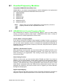
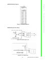
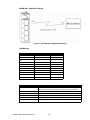
6.1.1 ADAM-5080 4-ch Counter/Frequency Module
With ADAM-5080 4-Channel Counter/Frequency Module, users can select either
counter or frequency mode for data output. ADAM-5080 offers users a variety of
very flexible and versatile applications such as below:
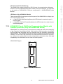
Counter Mode or Frequency Mode
If you want to measure the number of input signals for totalizer function, you may use
counter mode to measure quantities such as movement and flow quantity. Alternatively,
you can also select frequency mode to calculate the instantaneous differential of
quantities such as rotating speed, frequency or flow rate, and present them in specific
engineering formats.
Up/Down or Bi-direction Function
When operating in counter mode, you can choose either the Up/Down function or the
Bi-direction function for different application purposes. The counter will count up or
down according to your applications. This counting function helps users obtain the
most accurate data.
Alarm Setting Function
While in counter mode, you can set alarm status--Disable and Latch. If you want to
disable it, you can select Disable. If Latch status is selected, it means the Alarm status
will be "latched" whenever the alarm is being triggered. Once the alarm status being
"latched," it will thereafter stay in that triggered state. Users will have to issue a "Clear
Alarm Status" command to return the "latched" alarm status back to normal. Users can
designate the high-limit value and low-limit value to regulate your alarm behavior
through the utility program.
Digital Output Mapping
Users can either run the utility program or issue a "Set Alarm Connection" command to
designate a specific digital output module for the alarm signal to be sent through.
ADAM-5000 Series User Manual
54
Chapter 6
ADAM-5080 Module Diagram
ADAM-5080 Application Wiring
Figure 6.2 Isolated Input Level
Figure 6.3 TTL Input Level
55
ADAM-5000 Series User Manual
Counter/Frequency Modules
Figure 6.1 ADAM-5080 Module
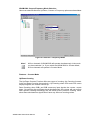
ADAM-5080 Counter/Frequency Mode Selection
Users can select Bi-direction, Up/Down, Counter or Frequency options as shown below.
Figure 6.4 Counter / Frequency Mode
Note!
All four channels of ADAM-5080 will operate simultaneously in the mode
you have selected. i.e. If you switch the ADAM-5080 to Counter Mode,
all four channels will operate in Counter Mode.
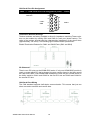
Features -- Counter Mode
Up/Down Counting
The Up/Down Counter Function offers two types of counting: Up Counting (increasingly) and Down Counting (decreasingly). Up Counting: when C0A+ and C0A- sense
any input signals, the counter counts up.
Down Counting: when C0B+ and C0B- sense any input signals, the counter counts
down. On receiving Up and Down signal simultaneously, the counter will not perform
each specific counting accordingly, but will remain at the previous counting value,
since these simultaneous signals won't have any effect on counting values.
ADAM-5000 Series User Manual
56
Chapter 6
Note!
If you need only one type of counting, connect C0A+ and C0A- for Up
Counting only; or connect C0B+ and C0B- for Down
Counting only.
Bi-direction Counting
For implementing Bi-direction Counting, you need to connect C0B+/D+ and C0B-/D- to
implement the control function for Up/Down Counting. Up Counting: when the input signal is within logic level "1", the counter value increases.
Figure 6.6 Wiring for Bi-direction Counting
Down Counting: when the input signal is within logic level "0", the counter value
decreases.
Note!
If users select TTL mode and don't connect C0B+ C0B-, the counter
value will increase. If users select Isolated mode and don't connect
C0B+ C0B-, the counter value will decrease.
Features -- Frequency Mode
If users want to select frequency mode, they can only utilize Up Counting type, and
can only connect to C0A+ and C0A-.
57
ADAM-5000 Series User Manual
Counter/Frequency Modules
Figure 6.5 Wiring for Up/Down Counting
Figure 6.7 Wiring for Frequency Mode
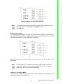
Features -- Alarm Setting
According to your application purposes, you can run the utility program to set different
limit values for High/Low Alarm.
Figure 6.8 Setting Alarm Limit
Setting Initial Counter Value
In order to utilize the alarm, users have to set a high-alarm limit value and/or a low
alarm limit value, and a initial value to fulfill the requirements for a basic alarm setting.
ADAM-5000 Series User Manual
58
Chapter 6
Figure 6.10 Sending Alarm Signal (Not Recommended)
Overflow Value
Overflow value is the number of times the counter value exceeds the Max/Min values you specified. When the counter value exceeds Maxi- mum value, the overflow
value increases; when the counter value goes under Minimum value, the overflow
value decreases. Besides, when the counter value runs beyond the range of Max/Min
value, it will continue counting from the initial value. Furthermore, if users want to
check the counter value to see if it is higher or lower than the Max/Min value, they can
use the "ReadOverflowFlag" library to gain readout of the over- flow value.
Getting the Totalizer Value
If users want to get the actual counter value, a formula such as follows can facilitate
an easy calculation from the initial counter value, overflow value and current counter
value:
Vtol = {|Vini - Vmin (or Vmax) |+ 1} x |Vvf| + |Vini - Vcur|
Vtol : totalizer value
Vini : initial counter value
Vmin : min. counter value = 0 (fixed value)
Vmax : max. counter value = 2 = 4,294,967,295 (fixed value)
Vvf : overflow value
Vcur : current counter value
32
Example: If the initial value =10, overflow value =4, min. value = 0, current counter value =
3, the totalizer value could be Totalizer value = {|10 - 0| + 1} x| 4 |+ |10 -3| = 51
59
ADAM-5000 Series User Manual
Counter/Frequency Modules
Figure 6.9 Sending Alarm Signal (Recommended Settings)
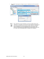
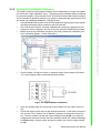
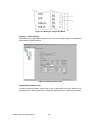
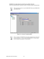
Features--Digital Output Mapping
If users want to use Digital Output function, ADAM utility is available for setting specifically which module, channel or slot to receive the alarm signals.
Figure 6.11 Digital Output Mapping
1.
2.
3.
4.
5.
6.
High Alarm State--Set Alarm state to "Latch" or "Disable".
High Alarm Limit--Set Alarm limit from 0 to 4,294,967,295.
High Alarm Output Mode--Enable or Disable D.O. Mapping.
High Alarm Output Slot--Users can select D.O Modules such as ADAM-5050,
ADAM-5055, ADAM-5056, ADAM-5060, ADAM-5068.
High Alarm Output Channel--Select Alarm Output Channel
Clear Latch Alarm--Users can select "Enable" or "Disable" option. When selecting
"Enable", the latch will be relieved and the alarm state will return to normal. Once
the alarm state returns to normal, the Clear Latch Alarm will return to "Disable".
TTL/Isolated Input Level
According to your need, you can select either TTL or Isolated Input Level by setting the configuration for the jumpers. Select the proper jumper settings for either
TTL or Isolated Input according to Figure 53. Please note that you must configure all
six jumpers to the correct con- figuration for proper function.
ADAM-5000 Series User Manual
60
Chapter 6
Figure 6.13 TTL/Isolated Input Level Selection
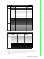
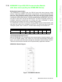
Table 6.1: ADAM-5080 Technical Specifications
Channel
4
Input Frequency
0.3 ~ 1000 Hz max. (Frequency mode) 5000 Hz max.
(Counter mode)
Input Level
Isolated or TTL level
Minimum Pulse Width
500 µ sec. (Frequency mode) 100 µ sec. (Counter mode)
Minimum Input Current
2mA (Isolated)
Isolated Input Level
Logic Level 0 : +1 V
Logic Level 1 : + 3.5 V to 30 V
TTL Input Level
Logic Level 0 : 0 V to 0.8 V
Logic Level 1 : 2.3 to 5 V
MAX
Isolated Voltage
1000 V
Mode
Counter (Up/Down, Bi-direction) Frequency
RMS
Programmable Digital Noise 8 ~ 65000 µ sec
Filter
61
ADAM-5000 Series User Manual
Counter/Frequency Modules
Figure 6.12 Jumper Location on the ADAM-5080 Module
ADAM-5081 4-ch High Speed Counter/Frequency Mode Selection
Users can select Bi-direction, Up/Down Counter or Frequency option as shown below.
Note!
This high speed module is only for ADAM-5560 Series and ADAM-5000/
485,ADAM-5000E.
Figure 6.14 Counter / Frequency Mode
Note!
All four channels of ADAM-5081 will operate simultaneously in the mode
you have selected. i.e. If you switch the ADAM-5081 to Counter Mode,
all four channels will operate in Counter Mode.
ADAM-5000 Series User Manual
62
Figure 6.15 Wiring for Up/Down Counting
Note!
If you need only one type of counting, connect C0A+ and C0A- for Up
Counting only; or connect C0B+ and C0B- for Down
Counting only.
Bi-direction Counting
For implementing Bi-direction Counting, you need to connect C0B+/D+ and C0B-/D- to
implement the control function for Up/Down Counting. Up Counting: when the input signal is within logic level "1", the counter value increases.
Figure 6.16 Wiring for Bi-direction Counting
Down Counting: when the input signal is within logic level "0", the counter value
decreases.
63
ADAM-5000 Series User Manual
Counter/Frequency Modules
Up/Down Counting
The Up/Down Counter Function offers two types of counting: Up Counting (increasingly) and Down Counting (decreasingly). Up Counting: when C0A+ and C0A- sense
any input signals, the counter counts up.
Down Counting: when C0B+ and C0B- sense any input signals, the counter counts
down. On receiving Up and Down signal simultaneously, the counter will not perform
each specific counting accordingly, but will remain at the previous counting value,
since these simultaneous signals won't have any effect on counting values.
Chapter 6
Features -- Counter Mode
Note!
If users select TTL mode and don't connect C0B+ C0B-, the counter
value will increase. If users select Isolated mode and don't connect
C0B+ C0B-, the counter value will decrease.
Features -- Frequency Mode
If users want to select frequency mode, they can only utilize Up Counting type, and
can only connect to C0A+ and C0A-.
Figure 6.17 Wiring for Frequency Mode
Features -- Alarm Setting
According to your application purposes, you can run the utility program to set different
limit values for High/Low Alarm.
Figure 6.18 Setting Alarm Limit
ADAM-5000 Series User Manual
64
Figure 6.20 Sending Alarm Signal (Not Recommended)
Overflow Value
Overflow value is the number of times the counter value exceeds the Max/Min values you specified. When the counter value exceeds Maxi- mum value, the overflow
value increases; when the counter value goes under Minimum value, the overflow
value decreases. Besides, when the counter value runs beyond the range of Max/Min
value, it will continue counting from the initial value. Furthermore, if users want to
check the counter value to see if it is higher or lower than the Max/Min value, they can
use the "ReadOverflowFlag" library to gain readout of the over- flow value.
Getting the Totalizer Value
If users want to get the actual counter value, a formula such as follows can facilitate
an easy calculation from the initial counter value, overflow value and current counter
value:
Vtol = {|Vini - Vmin (or Vmax) |+ 1} x |Vvf| + |Vini - Vcur|
Vtol : totalizer value
Vini : initial counter value
Vmin : min. counter value = 0 (fixed value)
Vmax : max. counter value = 2 = 4,294,967,295 (fixed value)
Vvf : overflow value
Vcur : current counter value
32
Example: If the initial value =10, overflow value =4, min. value = 0, current counter value =
3, the totalizer value could be Totalizer value = {|10 - 0| + 1} x| 4 |+ |10 -3| = 51
65
ADAM-5000 Series User Manual
Counter/Frequency Modules
Figure 6.19 Sending Alarm Signal (Recommended Settings)
Chapter 6
Setting Initial Counter Value
In order to utilize the alarm function, users have to set a high-alarm limit value and/or a
low alarm limit value, and an initial value to fulfill the requirements for a basic alarm
setting.
Features--Digital Output Mapping
If users want to use Digital Output function, ADAM utility is available for setting specifically which module, channel or slot to receive the alarm signals.
Figure 6.21 Digital Output Mapping
1.
2.
3.
4.
5.
6.
High Alarm State--Set Alarm state to "Latch" or "Disable".
High Alarm Limit--Set Alarm limit from 0 to 4,294,967,295.
High Alarm Output Mode--Enable or Disable D.O. Mapping.
High Alarm Output Slot--Users can select D.O Modules such as ADAM-5050,
ADAM-5055, ADAM-5056, ADAM-5060, ADAM-5068 for the alarm signal to be sent
through.
High Alarm Output Channel--Select Alarm Output Channel
Clear Latch Alarm--Users can select "Enable" or "Disable" option. When selecting
"Enable", the latch will be relieved and the alarm state will return to normal. Once
the alarm state returns to normal, the Clear Latch Alarm will return to "Disable".
TTL/Isolated Input Level
According to your need, you can select either TTL or Isolated Input Level by setting the configuration for the jumpers. Select the proper jumper settings for either
TTL or Isolated Input according to Figure 63. Please note that you must configure all
six jumpers to the correct con- figuration for proper function.
ADAM-5000 Series User Manual
66
Chapter 6
Figure 6.23 TTL/Isolated Input Level Select
Table 6.2: ADAM-5081 Technical Specifications
Channel
4
Input Frequency
5 Hz~1 MHz max. (Frequency mode)
1 MHz max. (Counter mode)
Input Level
Isolated or TTL level
Minimum Pulse Width
1 µ sec. (Frequency mode)
1 µ sec. (Counter mode)
Minimum Input Current
2mA (Isolated)
Isolated Input Level
Logic Level 0 : +3 V
Logic Level 1 : + 10 V to 30 V
TTL Input Level
Logic Level 0 : 0 V to 0.8 V
Logic Level 1 : 2.3 to 5 V
Isolated Voltage
2500 V
Mode
Counter (Up/Down, Bi-direction, up, A/B Phase) Frequency
MAX
RMS
Programmable Digital Noise 1 ~ 65000 µ sec
Filter
67
ADAM-5000 Series User Manual
Counter/Frequency Modules
Figure 6.22 Jumper Location on the ADAM-5081 Module
VCC
Cx+
Cx+
10~30V
VTTL
CxInternal
CxInternal
External
TTL input
Isolated input
VCC
External
DO
IVCC
Load
*Optional
GND
Internal
External
Isolated DO output
*Add a diode if load is relay
ADAM-5000 Series User Manual
68
Chapter
7
Serial Modules
7
7.1 Serial Modules
Compatible ADAM-5000 Series Main Units
The ADAM-5090 is a 4-port RS-232 communication module to be implemented with the
following Advantech ADAM-5000 series main units: ADAM-5510 (with library Version
V1.10 or above) ADAM-5511 (with library Version V1.10 or above)
7.1.1 ADAM-5090 4-port RS-232 Communication Module
Bi-direction Communication
The ADAM-5090 is equipped with four RS-232 ports, which makes it especially suitable for bi-direction communication. It can simultaneously read data from other thirdparty devices such as Bar Code and PLC as long as these devices are equipped with
a RS-232 interface. Furthermore, the ADAM-5090 can issue commands to control other
devices. It is fully integrated with the ADAM-5000, ADAM-5500 and ADAM-4000 series,
and transmits data to each other through the RS-232 port. The whole integrated
system is an intelligent stand-alone system and can connect and issue commands
to control devices such as printers and PLCs in remote factory location.
The ADAM-5090 transmits and receives data by polling communication, and each port
can receive up to 128 bytes in the FIFO. For continuous data longer than 128 bytes,
please refer to Table 20 for Baud Rate setting to avoid data loss.
Table 7.1: Baud Rate Settings
Baud Rate (bps)
115200
57600
38400 19200
9600
4800
2400
Polling interval (ms)
11.11
22.22
33.33 66.66
133.33 266.66 533.33
Communication Backup Function
With the ADAM-5090 you can implement dual communication channels between your
PC and the ADAM system. Even when one of the two communication channels is
down, your system can still function through the alternative communication channel.
This dual communication channels can be implemented by application software.
ADAM-5090 Module Diagram
Figure 7.1 ADAM-5090 Module
ADAM-5000 Series User Manual
70
Chapter 7
ADAM-5090 Application Wiring
Table 7.2: Pin Mapping
PIN Name
RJ-48
DB9
/DCD
1
1
RX
2
2
TX
3
3
/DTR
4
4
GND
5
5
/DSR
6
6
/RTS
7
7
/CTS
8
8
RI or +5V
9
9
GND
10
X
Table 7.3: ADAM-5090 Technical Specifications
Function
Provides communication ports for the ADAM-5510 to integrate
other devices with communication function into your system
Electrical Interface
4 ports (RS-232)
Communication Rates 4800, 9600, 19200, 38400, 115200bps
FIFO
128 bytes/per UART (Tx/Rx)
Indicator
Tx (Orange), Rx (Green)
Power Required
100mA @ 5VDC Default in RI mode (*)
User can define the communication ports with 5VDC output by switching the jumper,
and the maximum current output is 400mA.
71
ADAM-5000 Series User Manual
Serial Modules
Figure 7.2 ADAM-5090 Application Wiring
I/O Slots and I/O Ports Numbering
The ADAM-5090 module provides four RS-232 ports for communication with target
devices. The ports are numbered 1 through 4. For programming, the definition of port
number depends on the slot number and port number. For example, the second port
on the ADAM-5090 in slot 1 is defined to port 12.
Jumper Settings
This section tells you how to set the jumpers to configure your ADAM-5090 module.
There are four jumpers on the PC Board. User can choose RI signal or 5V output for
each port by setting these jumpers (system default is RI signal).
The following figure shows the location of the jumpers:
Figure 7.3 Jumper Locations on the CPU Card
Figure 7.4 Jumper Settings
ADAM-5000 Series User Manual
72
Quick Start
Step 1: Get your host PC ready, and run the ADAM-5510 Utility Software.
Step 2: Install the ADAM-5090 Module and power on your ADAM-5510 main unit.
Step 3: Download the executable program to the main unit
Step 4: Monitor the ADAM-5090 Module’s current status from the PC through the utility software.
A basic example program for the ADAM-5090
main ()
{
//Install the port you would like to use. Here we install slot 0, port 1.
port_install(1);
// Here we install slot 2, port 2.
port_install(22);
//Select working port. Here we select slot 0, port 1.
port_select(1);
//Set port data format.
//Here we set the data format of port 1 as lengh:8; parity:0;stop_bit:1. (N81)
port_set_format(1,8,0,1);
//Set port speed. Here we set communication speed of port 1 as 115200 bps.
//(L is necessary)
port_set_speed(1,115200L);
//Enable Port FIFO. Here we enable 128 byte FIFO for port1.
73
ADAM-5000 Series User Manual
Serial Modules
Configuring Your ADAM-5090 Module
This section explains how to configure an ADAM-5090 module before implementing it
into your application.
Chapter 7
LED Status of the ADAM-5090 Module
There are two LEDs for each port on the front panel of the ADAM-5090 to display specific communication status:
Green LED (RX): Data Receiving Status; the LED indicator is on when the port is
receiving data.
Orange LED (TX): Data Transmitting Status; the LED indicator is on when the port
is transmitting data.
port_enable_fifo(1);
//After these above settings are enabled, you can apply any other function library to
implement your program.
}
—A receive-and-transmit example program for the ADAM-5090
main()
{
int err_value, char character port_installed(1)
:
:
port_enable_fifo(1);
//check whether error has been received or not
err_value=port_rx_error(1);
//if error detected, print out the message
if(err_value)
{
printf(“\n Rx Error, The LSR Value=%02X”, Err_value)”;
}
//check whether FIFO receives data or not; if data received, read a character
if(port_rx_ready(1))
{
character=port_rx(1);
}
//check whether FIFO is empty or not, if empty, send a character
if(port_tx_empty(1));
{
port_tx(1, character)
}
}
ADAM-5000 Series User Manual
74
Table 7.4: Baud Rate Settings
Baud Rate (bps)
115200
Polling interval (ms) 11.11
57600
38400
19200
9600
4800
2400
22.22
33.33
66.66
133.33 266.66 533.33
Communication Backup Function
With the ADAM-5091 you can implement dual communication channels between your
PC and the ADAM system. Even when one of the two communication channels is
down, your system can still function through the alternative communication channel.
This dual communication channels can be implemented by application software.
ADAM-5091 Module Diagram
Figure 7.5 ADAM-5091 Module
75
ADAM-5000 Series User Manual
Serial Modules
Bi-direction Communication
The ADAM-5091 is equipped with four RS-232 ports with share interrupt, which
makes it especially suitable for bi-direction communication. It can simultaneously read
data from other third-party devices such as Bar Code and PLC as long as these
devices are equipped with a RS-232 interface. Furthermore, the ADAM-5091 can issue
commands to control other devices. It is fully integrated with the ADAM-5560, and transmits data to each other through the RS-232 port. The whole integrated system is an
intelligent stand-alone system and can connect and issue commands to control
devices such as printers and PLCs in remote factory location.
The ADAM-5091 transmits and receives data by sharing interrupt communication, and
each port can receive up to 128 bytes in the FIFO. For continuous data longer than
128 bytes, please refer to Table 27 for Baud Rate setting to avoid data loss.
Chapter 7
7.1.2 ADAM-5091 4-port RS-232 Communication Module
with share interrupt (Only for ADAM-5560 Series)
ADAM-5091 Application Wiring
Figure 7.6 ADAM-5091 Application Wiring
PIN Mapping
Table 7.5: PIN Mapping
PIN Name
RJ-48
DB9
/DCD
1
1
RX
2
2
TX
3
3
/DTR
4
4
GND
5
5
/DSR
6
6
/RTS
7
7
/CTS
8
8
RI or +5V
9
9
GND
10
X
Table 7.6: ADAM-5091 Technical Specifications
Function
Provides communication ports for the ADAM-5560 to integrate
other devices with communication function into your system
Electrical Interface
4 ports RS-232
Communication Rates
4800, 9600, 19200, 38400, 115200bps
FIFO
128 bytes/per UART (Tx/Rx)
Indicator
Tx (Green), Rx (Red)
Power Required
100mA @ 5VDC Default in RI mode (*)
ADAM-5000 Series User Manual
76
7.1.3 ADAM-5095 2-port CAN Serial Communication Module with
isolation protection (Only for ADAM-5560 Series)
ADAM-5095 is a special purpose communication module that offers the connectivity
of the Controller Area Network (CAN). With its built-in CAN controllers, the ADAM5095 provides bus arbitration and error detection with an automatic transmission
repeat function. This drastically reduces the chance of data loss and ensures system
reliability. The on-board CAN controllers are located at different positions in the memory, and you can run both CAN controllers independently at the same time. With high
compatibility, the ADAM-5095 can be used in diverse systems.
ADAM-5095 Diagram
2 CAN
ADAM-5095
Port1
Tx
Rx
Port2
Tx
Rx
Figure 7.7 ADAM-5095 Module
77
ADAM-5000 Series User Manual
Serial Modules
LED Status of the ADAM-5091 Module
There are two LEDs for each port on the front panel of the ADAM-5091 to display specific communication status:
a. Red LED (RX): Data Receiving Status; the LED indicator is on when the port is
receiving data.
b. Green LED (TX): Data Transmitting Status; the LED indicator is on when the port
is transmitting data.
Chapter 7
I/O Slots and I/O Port Numbering
The ADAM-5091 module provides four RS-232 ports for communication with target
devices. For more information about the number of slot and COM port, you may refer
to the section of "ADAM-5091 COM port configuration" in ADAM-5560KW series
Manual.
CAN Serial Port Pin Assignment
Table 7.7: CAN Serial Port Pin Assignment (CAN1 ~ CAN2)
CAN Signal
Definition
7
3
CAN-H
1
6
2
CAN-L
GND
8
4
9
5
Pin
Termination Resistor Settings
Terminal resistors are factory installed to allow for impedance matching.These resistors can be enabled by utilizing SW1 and SW2 for each port (shown below). The
value of the resistor should equal the characteristic impedance of the signal wires
(approximately 120 ohms). The following figure shows resistor placements.
Enable Termination Resistor for CAN1 and CAN2 Ports (SW1 and SW2)
I/O Slots and I/O Ports Numbering
There’re two PCI slots on the ADAM-5560 series. If only one ADAM-5095 module is
used, no mater which PCI slot is plugged, the port number shown in the Utility would
be CAN1 and CAN2. If two ADAM-5095 modules are used, the port number shown in
the Utility would be CAN1 and CAN2 for the first PCI slot and CAN3 and CAN4 for
the second PCI slot.
CAN Serial Port Wiring
The CAN standard supports half-duplex communication. This means that just two
wires are used to transmit and receive data.
ADAM-5000 Series User Manual
78
Table 7.8: ADAM-5095 DTE Pin Wiring
Pin
ADAM-5095 DTE(DB9-M) Pin Signal
DTE Pin Signal
7
CAN-H
CAN-H
3
GND
GND
2
CAN-L
CAN-L
Table 7.9: Maximum Bit rate vs. Bus Length
Bit Rate
Bus Length
1M bps
25m
800k bps
50m
500k bps
100m
250k bps
250m
125k bps
500m
50k bps
1000m
20k bps
2500m
10k bps
5000m
79
ADAM-5000 Series User Manual
Serial Modules
Maximum Bit Rate vs. Bus Length
For a Controller Area Network, the maximum possible bus length depends on the bit
rate. The bit rate can always be slower than the maximum possible speed for a given
bus length. Conversely, the bus length can be shorter than the maximum possible
bus length for a given transmission speed.
Chapter 7
Wiring connections are as follows:
ADAM-5000 Series User Manual
80
Chapter
8
Storage Modules
8
8.1 Storage Modules
8.1.1 ADAM-5030 2-slot SD Storage Module with 2x USB2.0
ADAM-5030 is a 2-slot secure digital card storage module that provides 2 USB ports
and 2 SD slots. It is fully compliant with USB 2.0 and FAT16 and is also low power
consuming, at only 0.5W. According the volume of SD Card, you can extend the
memory of your controller up 2 GB.
Compatible with ADAM-5560 Series Main Units
The ADAM-5030 interfaces with the main unit through the PCI bus. The ADAM5560 series main unit is equipped with a PCI interface connector on 2 slots.
Through adapting the ADAM-5030, the ADAM-5560 can extend the storage
capacity easily.
The ADAM-5030 can also be extended too two USB2.0 ports. These USB ports act
in the same way as the ports on the ADAM-5560 main units.
ADAM-5030 Diagram
Figure 8.1 ADAM-5030 Module Frontal View
Table 8.1: Technical Specifications of ADAM-5030
USB Type
USB Rev 2.0 (Compliant)
USB Number
2
Storage Type
SD (Secure Digital Card)
Storage Number
2
Operating Temperature
0~60 (32~140)
Certification
CE
Power Consumption
3 W (Max)
Max Storage
1G (Max) x 2
Format
FAT16
Surge Protection
10kW
Hot Swap
Yes
ADAM-5000 Series User Manual
82