1
Hytec Electronics Ltd
Hytec EPICS Driver User Manual
DRV/2011/EPICS
Hytec EPICS Driver User
Manual
Document Reference:
Name
DRV/2011/EPICS
Signature
Date
Hytec Project Manager
Graham Cross
24 January 2011
Author
Jim S Chen
24 January 2011
Issuing Organisation:
Issue 12
Hytec Electronics Ltd
Page 1 of 205
Hytec Electronics Ltd
Hytec EPICS Driver User Manual
Classification:
DRV/2011/EPICS
Unclassified
Distribution List
Copy
Registered Holder
Master
Hytec Electronics Ltd
Document Change History
Version Release
date
Changes
Modified Updated
Sections
Document
Approved
Issue 0
24 January
2011
Initial draft
Issue 1
25 May 2011
Preliminary release
Issue 2
23 June 2011
Added example for 8601. Added ARCH
variable setting for building Linux IOC
for Makefile under iocBootexample.
18
Issue 3
27 June 2011
Amended errors in 8601 start up script.
18
Issue 4
13 July 2011
Added note to add iocsh() in start up
script when configure routine has more
than 10 parameters for VxWorks.
18
Issue 5
15 December
2011
Added 8413 asyn, 8415 asyn driver
documents. Modified 8417 asyn driver
document.
13, 15, 17
Issue 6
26 January
Added 8411 asyn driver document
12
Issue 12
Page 2 of 205
Hytec Electronics Ltd
Hytec EPICS Driver User Manual
DRV/2011/EPICS
2012
Issue 7
30 January
2012
Added 8522 Histogram Scaler Driver
10
Issue 8
02 February
2012
Added 8402 DAC asyn driver
16
Issue 9
09 March
2012
Corrected errors for setting 8002/8004
carrier card.
3
Issue 10
04 May 2012
Corrected MEMOFFS calculation
description for 8002 configuration call.
Should use VME_A32_MSTR_BUS,
not VME_A32_MSTR_LOCAL. Also
corrected _LIB reference for building
example of the ADC and DAC modules
3, 10, 12,
13, 14, 15,
16, 17
Issue 11
10 August
2012
Upgraded 8522 to the full version of
histogram scaler and preset scaler.
10
Issue 12
25 March
2013
Issue 12
1. Added 8424 ADC user manual
2. Added support for Concurrent
VME processor for Linux
3. Added 8001 digital IO and
carrier card user manual
19, 20 and
nearly all
chapters
Page 3 of 205
Hytec Electronics Ltd
Hytec EPICS Driver User Manual
DRV/2011/EPICS
Table of Contents
.............................................................................................................................................................................. 1
1.
General Information ................................................................................................................................... 10
The Purpose of the Document ....................................................................................................................... 10
A Brief View of EPICS Application and Hytec Support .................................................................................... 10
Content of this document .............................................................................................................................. 12
2.
Linux Device Driver Installation ................................................................................................................ 13
Download the driver ....................................................................................................................................... 13
PCI device driver ............................................................................................................................................. 13
UART device driver ......................................................................................................................................... 16
3.
Hytec Carrier Card EPICS Driver .............................................................................................................. 19
General information and software download ................................................................................................ 19
Install devLib2 PCI support module ................................................................................................................ 20
Install IPAC module and carrier driver............................................................................................................ 20
Shell command to load the carrier driver in st.cmd ....................................................................................... 23
4.
Start up Script ............................................................................................................................................. 30
Linux IOC ......................................................................................................................................................... 30
VxWorks IOC ................................................................................................................................................... 30
RTEMS IOC ...................................................................................................................................................... 31
The Common Part ........................................................................................................................................... 31
5.
Set up RTEMS IOC application loading for IOC9010 ............................................................................... 34
Building the IOC application ........................................................................................................................... 34
Set up loading RTEMS image .......................................................................................................................... 34
Set up DHCP and BOOTP server for loading EPICS ......................................................................................... 35
Start the IOC ................................................................................................................................................... 36
6.
Hy8505 16bit Digital IO EPICS Device Driver ......................................................................................... 37
Download the Software.................................................................................................................................. 37
Support Modules ............................................................................................................................................ 37
Building the module library ............................................................................................................................ 37
Configuration of the Carrier Card ................................................................................................................... 38
Issue 12
Page 4 of 205
Hytec Electronics Ltd
Hytec EPICS Driver User Manual
DRV/2011/EPICS
Database definition file .................................................................................................................................. 38
Testing Database(s) ........................................................................................................................................ 38
Building an Example Application .................................................................................................................... 38
Configuration Shell Command for Start up Script .......................................................................................... 40
Start up Script Example .................................................................................................................................. 41
7.
Hy8506 48bit Digital IO EPICS Device Driver ......................................................................................... 43
Download the Software.................................................................................................................................. 43
Support Modules ............................................................................................................................................ 43
Building the module library ............................................................................................................................ 43
Configuration of the Carrier Card ................................................................................................................... 44
Database definition file .................................................................................................................................. 44
Testing Database(s) ........................................................................................................................................ 44
Building an Example Application .................................................................................................................... 44
Configuration Shell Commands for Start up Script ........................................................................................ 46
Start up Script Example .................................................................................................................................. 47
8.
Hy8515/8516 Serial Port Device Driver .................................................................................................... 49
General Information ....................................................................................................................................... 49
Download the Software.................................................................................................................................. 49
Support Modules ............................................................................................................................................ 49
Build the module library ................................................................................................................................. 49
Configuration of the Carrier Card ................................................................................................................... 50
Database definition file .................................................................................................................................. 50
Building an Example Application .................................................................................................................... 50
Configuration Shell Command for Start up Script .......................................................................................... 51
Some notes ..................................................................................................................................................... 52
9.
Hy8512 Scaler EPICS Device Driver ......................................................................................................... 53
General Information ....................................................................................................................................... 53
Download the Software.................................................................................................................................. 53
Support Modules ............................................................................................................................................ 53
Build the module library ................................................................................................................................. 54
Configuration of the Carrier Card ................................................................................................................... 54
Database definition file .................................................................................................................................. 54
Issue 12
Page 5 of 205
Hytec Electronics Ltd
Hytec EPICS Driver User Manual
DRV/2011/EPICS
Testing Database(s) ........................................................................................................................................ 55
Building an Example Application .................................................................................................................... 55
Configuration Shell Command for Start up Script .......................................................................................... 57
Start up Script Example .................................................................................................................................. 58
10.
Hy8522 Histogram Scaler EPICS Device Driver ................................................................................... 60
General Information ....................................................................................................................................... 60
Download the Software.................................................................................................................................. 69
Support Modules ............................................................................................................................................ 70
Build the module library ................................................................................................................................. 70
Configuration of the Carrier Card ................................................................................................................... 70
Database definition file .................................................................................................................................. 71
Testing Database(s) ........................................................................................................................................ 71
Building an Example Application .................................................................................................................... 73
Configuration Shell Command for Start up Script .......................................................................................... 75
Start up Script Example .................................................................................................................................. 79
11.
Hy8401 8 Channel 16bit ADC EPICS Asyn Device Driver .................................................................. 83
General Information ....................................................................................................................................... 83
Download the Software.................................................................................................................................. 86
Support Modules ............................................................................................................................................ 86
Build the module library ................................................................................................................................. 87
Configuration of the Carrier Card ................................................................................................................... 87
Database definition file .................................................................................................................................. 87
Testing Database(s) ........................................................................................................................................ 87
Building an Example Application .................................................................................................................... 89
Configuration Shell Command for Start up Script .......................................................................................... 91
Start up Script Example .................................................................................................................................. 92
12.
Hy8411 16 Channel 16bit ADC with 256 FIFO Memory EPICS Device Driver .................................. 95
General Information ....................................................................................................................................... 95
Download the Software.................................................................................................................................. 95
Support Modules ............................................................................................................................................ 95
Build the module library ................................................................................................................................. 96
Configuration of the Carrier Card ................................................................................................................... 96
Issue 12
Page 6 of 205
Hytec Electronics Ltd
Hytec EPICS Driver User Manual
DRV/2011/EPICS
Database definition file .................................................................................................................................. 96
Testing Database(s) ........................................................................................................................................ 96
Building an Example Application .................................................................................................................... 98
Configuration Shell Command for Start up Script ........................................................................................ 100
Start up Script Example ................................................................................................................................ 101
13.
Hy8413 16 Channel 16bit ADC EPICS Device Driver ........................................................................ 104
General Information ..................................................................................................................................... 104
Download the Software................................................................................................................................ 104
Support Modules .......................................................................................................................................... 105
Building the module library .......................................................................................................................... 105
Configuration of the Carrier Card ................................................................................................................. 105
Database definition file ................................................................................................................................ 105
Testing Database(s) ...................................................................................................................................... 106
Building an Example Application .................................................................................................................. 108
Configuration Shell Command for Start-up Script ........................................................................................ 110
Start up Script Example ................................................................................................................................ 111
14.
Hy8414 16 Channel 16bit ADC EPICS Asyn Device Driver (Automatic Calibration) ....................... 113
General Information ..................................................................................................................................... 113
Download the Software................................................................................................................................ 116
Support Modules .......................................................................................................................................... 116
Build the module library ............................................................................................................................... 117
Configuration of the Carrier Card ................................................................................................................. 117
Database definition file ................................................................................................................................ 117
Testing Database(s) ...................................................................................................................................... 117
Building an Example Application .................................................................................................................. 119
Configuration Shell Command for Start-up Script ........................................................................................ 121
Start up Script Example ................................................................................................................................ 122
15.
Hy8417 8 Channel 24bit ADC EPICS Asyn Device Driver (Automatic Calibration) ......................... 125
General Information ..................................................................................................................................... 125
Download the Software................................................................................................................................ 128
Support Modules .......................................................................................................................................... 128
Building the module library .......................................................................................................................... 129
Issue 12
Page 7 of 205
Hytec Electronics Ltd
Hytec EPICS Driver User Manual
DRV/2011/EPICS
Configuration of the Carrier Card ................................................................................................................. 129
Database definition file ................................................................................................................................ 129
Testing Database(s) ...................................................................................................................................... 129
Building an Example Application .................................................................................................................. 132
Configuration Shell Command for Start-up Script ........................................................................................ 134
Start up Script Example ................................................................................................................................ 135
16.
Hy8402 16 Channel 16bit DAC EPICS Device Driver ........................................................................ 138
General Information ..................................................................................................................................... 138
Download the Software................................................................................................................................ 139
Support Modules .......................................................................................................................................... 139
Building the module library .......................................................................................................................... 140
Configuration of the Carrier Card ................................................................................................................. 140
Database definition file ................................................................................................................................ 140
Testing Database(s) ...................................................................................................................................... 141
Building an Example Application .................................................................................................................. 143
Configuration Shell Command for Start-up Script ........................................................................................ 145
Start up Script Example ................................................................................................................................ 146
17.
Hy8415 16 Channel 18bit DAC EPICS Device Driver (Automatic Calibration) ................................ 149
General Information ..................................................................................................................................... 149
Download the Software................................................................................................................................ 149
Support Modules .......................................................................................................................................... 149
Building the module library .......................................................................................................................... 150
Configuration of the Carrier Card ................................................................................................................. 150
Database definition file ................................................................................................................................ 150
Testing Database(s) ...................................................................................................................................... 150
Building an Example Application .................................................................................................................. 154
Configuration Shell Command for Start-up Script ........................................................................................ 155
Start-up Script Example ................................................................................................................................ 157
18.
Hy8601 EPICS “Model 3”Asyn Device Driver ................................................................................... 160
Download the Software................................................................................................................................ 160
Support Modules .......................................................................................................................................... 160
Building the module library .......................................................................................................................... 160
Issue 12
Page 8 of 205
Hytec Electronics Ltd
Hytec EPICS Driver User Manual
DRV/2011/EPICS
Configuration of the Carrier Card ................................................................................................................. 161
Database definition file ................................................................................................................................ 161
Testing Database(s) ...................................................................................................................................... 161
Building an Example Application .................................................................................................................. 163
Configuration Shell Command for Start-up Script ........................................................................................ 165
Start-up Script Example ................................................................................................................................ 167
19.
Hy8424 4 Channel 16bit 1MHz ADC EPICS Asyn Device Driver (Automatic Calibration) .............. 169
General Information ..................................................................................................................................... 169
Download the Software................................................................................................................................ 173
Support Modules .......................................................................................................................................... 173
Building the module library .......................................................................................................................... 174
Configuration of the Carrier Card ................................................................................................................. 174
Database definition file ................................................................................................................................ 174
Testing Database(s) ...................................................................................................................................... 174
Building an Example Application .................................................................................................................. 179
Configuration Shell Command for Start-up Script ........................................................................................ 180
Start up Script Example ................................................................................................................................ 184
20.
Acknowledgement ................................................................................................................................ 188
21.
Bibliography ......................................................................................................................................... 204
Issue 12
Page 9 of 205
Hytec Electronics Ltd
Hytec EPICS Driver User Manual
DRV/2011/EPICS
1. General Information
The Purpose of the Document
This document intends to aid those who used, are using or will use Hytec equipment in EPICS
environment. It describes in details as how to setup and configure the device drivers (mainly EPICS,
and some in Linux operating system) for various Hytec carrier cards and IP modules under different
operating systems such as VxWorks, RTEMS and Linux etc. It is not written for beginners. The
readers are assumed to have already gained certain knowledge of:
-
EPICS environment – EPICS core, database and how to build an application etc.
Data acquisition concepts such as ADC, DAC, Digital I/O, Scaler, serial port communication
and step motor controller etc.
Various operating systems like VxWorks, RTEMS, Linux and Windows etc.
A Brief View of EPICS Application and Hytec Support
With the evolution of EPICS core from 3.13 to 3.14 and the soon coming 3.15, and the support for
different architectures such as CAMAC, VME, PCI/PCIe and Micro-TCA etc. Hytec EPICS device
drivers have been following all the development paths. We now support nearly all versions of EPICS
and the majority of the architectures.
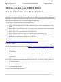
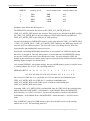
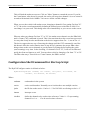
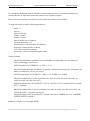
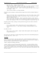
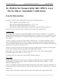
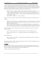
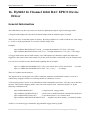
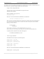
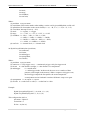
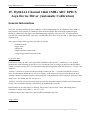
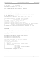
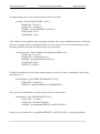
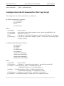
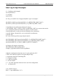
An overview of EPICS application architecture is illustrated below.
Issue 12
Page 10 of 205
Hytec Electronics Ltd
Hytec EPICS Driver User Manual
DRV/2011/EPICS
User Application (EPICS Client)
EPICS Core / Channel Access
Record / Device / Driver Support
(Carrier, Asyn, synApps, Hy8xxx etc)
Board Support Package (BSP)
(VxWorks, RTEMS)
Device Driver
(Linux, Windows)
Operating System
(VxWorks, RTEMS, Linux, Windows)
Figure 1 - EPICS Application Architecture
This document mainly focuses on EPICS core 3.14 and above.
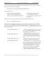
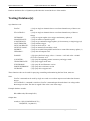
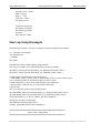
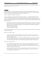
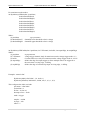
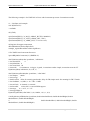
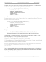
The architectures supported by Hytec drivers are: VME/VEM64x, PCI/PCIe, Micro-TCA under
operating systems such as VxWorks, RTEMS, Linux etc. Below is a table of current support matrix
of different carriers (with their support modules) under different operating systems.
Table 1 – Hytec driver support matrix
Carrier
VxWorks
RTEMS
Linux
8002~8004
Ipac + drvHy8002.c
Ipac + drvHy8002.c
X
X
Ipac +
drvHy8002Concurrent.c
Hytec VME UART
device driver
Ipac +
drvHyLinuxCarrier.c +
Hytec PCI/UART device
driver
X
X
X
Ipac +
Ipac +
drvHyRTEMSCarrier .c drvHyLinuxCarrier.c +
Hytec PCI/UART device
+ devlib2
driver
VME
6335
PCIe
7002
MicroTCA
IOC9010
PCI
Issue 12
Ipac +
drvHyLinuxCarrier.c +
Hytec PCI/UART device
driver
Page 11 of 205
Hytec Electronics Ltd
Hytec EPICS Driver User Manual
DRV/2011/EPICS
X – not supported
Content of this document
The content of this document covers three parts:
-
Linux device drivers
EPICS carrier card driver (ipac)
EPICS IP module drivers.
The Linux device drivers are only needed when building EPICS IOC on Linux PC box (PCI/PCIe
bus) with Hytec carrier cards such as IOC9010, PCIe 6335 and uTCA7002/7003. These drivers have
to be loaded before running EPICS application.
When using Concurrent VME processor board with Linux, Concurrent device driver has to be loaded
first as well. This is supplied by the BSP (Board Support Package).
There are a number of carrier cards that are suitable for different architectures.
-
VME carriers: 8001, 8002, 8003, 4004. Maximum 4 IP cards
IOC9010 1U blade. Maximum 6 IP cards
PCIe carrier: 6335. Maximum 2 IP cards
uTCA: 7002. Maximum 1 IP card and 7003. Maximum 2 IP cards
IP cards include:
-
ADC: 8401, 8411, 8413, 8403, 8414, 8417, 8424, 8418
DAC: 8402, 8415
Digital I/O: 8505, 8506
Serial communication: 8515, 8516
Step motor: 8601
Scaler: 8512, 8522
Issue 12
Page 12 of 205
Hytec Electronics Ltd
Hytec EPICS Driver User Manual
DRV/2011/EPICS
2. Linux Device Driver Installation
This section is only needed when porting EPICS application on a Linux box with carrier card of
either IOC9010, 6335 or uTCA7002/7003 on a normal PCi/PCIe bus PC.
For those who use Hytec carrier cards such as IOC9010 blade or PCIe 6335 or uTCA 7002/7003 on
Linux system with PCI/PCIe bus, there isn’t a board support package but Hytec provides a set of low
level kernel device drivers to suit the EPICS support needs. These include two packages at present:
PCI device driver and UART device driver.
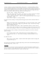
Download the driver
The Linux PCI and UART device drivers can be downloaded from Hytec website http://www.hytecelectronics.co.uk/Download.aspx . The file would be something like this:
Hytec-Linux-Device_drivers-dd-mm-yyyy.tar.gz
PCI device driver
PCI device driver is a generic driver that functions as the BSP part which glues the EPICS carrier
driver to the hardware. Almost all Hytec IP cards need it to gain access to the hardware I/O registers
and memory space and handle interrupts.
The driver provides user space memory mapping to either I/O registers or memory space. This allows
the fastest access to the hardware (eliminates the latency of ioctl calls). It also matches the same
access mechanism as in the VxWorks or RTEMS that makes the upper layer driver (IP drivers) code
operating system independent (OSI compliant).
The interrupt is a fast interrupt as well. This together with the drvHyLinuxCarrier.c driver in the
IPAC module forms the interrupt mechanism of dispatching the interrupt services to the correct
carrier and right IP driver code.
The PCI device driver supports multiple PCI/PCIe carrier devices such as PCIe6335 uTCA7002/7003
as well as single carrier system like IOC9010. In the case of multiple device system, each carrier is
recognised by the identity (ID) settings on the carrier cards.
To install the driver,
Issue 12
Page 13 of 205
Hytec Electronics Ltd
Hytec EPICS Driver User Manual
DRV/2011/EPICS
Set up jumpers
For multiple carrier system, the carrier card ID is defined by a row of jumpers. It has 5 rows so it can
define the carrier ID form 0 ~31. Please refer to hardware manual to locate the jumpers.
Note,
A. In multiple carrier system, each carrier ID has to be unique.
B. Even there is only one card in the system, you can either set the jumpers or leave all of them
open which gives ID 0.
This ID will become part of the device name created by the IOC9010_create script discussed
below. And it will also be passed as an argument to the carrier configuration routine when
loading the carrier driver (ipac module) discussed in the next chapter.
For single carrier like IOC9010, there is no jumper to set.
Copy the tar file to the PC
Hytec-Linux-Device_drivers-dd-mm-yyyy.tar.gz
(dd-mm-yyy is the date of release)
to any directory say, /root for example and unzip it from there. It will install the code to the following
directories:
PCI driver:
/root/IOCBlade9010/pci
UART driver: /root/IOCBlade9010/uart
Re-build the device driver
To build the PCI device driver, go to /root/IOCBlade9010/pci directory and do a “make”.
Install the driver
To install (load) the device driver and create the device(s), execute the two scripts below in the
/root/IOCBlade9010/pci directory.
IOC9010_load
IOC9010_create
The first one is to load the driver and the second one is to create the device(s). Alternatively, one can
include these scripts into the .bash_profile (a hidden file) under /root for “root” user or under
/home/xxx for “xxx” user so that the driver can be loaded automatically during system log in.
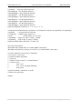
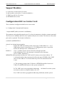
The “IOC9010_load” script looks like this:
Issue 12
Page 14 of 205
Hytec Electronics Ltd
Hytec EPICS Driver User Manual
DRV/2011/EPICS
#!/bin/sh
# $Id: IOC9010_load,v 1.4 2011/05/20 17:12:49 Jim Chen Exp $
module="9010LinuxDriver"
device="IOC9010"
mode="664"
# invoke insmod with all arguments we got
# and use a pathname, as insmod doesn't look in . by default
/sbin/insmod /root/IOCBlade9010/pci/$module.ko $* || exit 1
echo Please run ./IOC9010_create to create devices. Try ./IOC9010_create –help
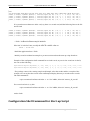
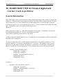
The “IOC9010_create” script is different as per the single carrier or multiple carriers. It looks like
this
#!/bin/sh
# $Id: IOC9010_create,v 1.0 2011/05/20 016:57:49 Jim Chen Exp $
module="9010LinuxDriver"
device="IOC9010"
mode="664"
# Remove stale nodes and replace them, then give gid and perms
# Usually the script is shorter, it's scull that has several devices in it.
rm -f /dev/${device}*
# retrieve major number
major=$(awk "\$2==\"$device\" {print \$1}" /proc/devices)
echo
if [ $# -eq 0 ] ; then
mknod /dev/${device} c $major 0
chmod $mode /dev/${device}
echo Device ${device} major=$major mimor=0 has been created.
echo
exit
else
until [ -z $1 ] ; do
mknod /dev/${device}$1 c $major $1
if [[ $? -ne 0 ]] ; then
exit
Issue 12
Page 15 of 205
Hytec Electronics Ltd
Hytec EPICS Driver User Manual
DRV/2011/EPICS
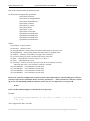
fi
echo Device ${device}$1 major=$major mimor=$1 has been created.
chmod $mode /dev/${device}$1
shift
done
fi
echo
In the case of a single carrier system (IOC9010), there is only one PCI device. To create the device,
just run the device creation script without parameter.
IOC9010_create
For multiple carrier system (PCIe6335 and uTCA7002/7003), the carrier IDs set by the jumpers need
to be passed to the script to create different devices distinguished by the IDs as below
IOC9010_create 3 5
which will create two devices IOC90103 and IOC90105.
Check installation
To check the driver is loaded properly, run the shell command:
dmesg
It should list all the resources (memory mappings and interrupt assignment etc) acquired to the carrier
card(s) by the loading process.
To check the devices created please run shell command:
ls /dev
You should see one or more IOC9010 device(s) listed there with names IOC9010x – x is the device
ID number.
Uninstall
To remove the driver and devices, run command
IOC9010_unload
UART device driver
Issue 12
Page 16 of 205
Hytec Electronics Ltd
Hytec EPICS Driver User Manual
DRV/2011/EPICS
This UART device driver is specific designed for Hytec 8515/8516 serial IP modules. Upon loading
the driver it automatically detects all carrier cards and all the 8515/8516 modules installed on these
carriers. It then creates Linux standard UART ports for each individual serial channel of the IP cards
so that the user can use them just like the normal on board serial ports such as ttyS0 ~ ttyS3 etc.
The number of tty devices the driver creates depends on the 8516/8516 IP modules. In the case of
IOC9010, the maximum IP cards it can handle is 6 so the maximum tty devices the driver can create
is 48 (each 8515 or 8516 has 8 channels) named from ttyHy0 ~ ttyHy47, where the first 8 ports
(ttyHy0 ~ ttyHy7) are related to IP module in slot A and second 8 ports (ttyHy8 ~ ttyHy15) are
related to IP in slot B and so forth or the next valid 8515/8516 IP module.
Install driver
After un-tar the zip file downloaded from the website, do a make to re-build the module in
/root/IOCBlade9010/uart directory. Then go to /root/IOCBlade9010/uart to load the driver by
executing
./uart_load
script.
Verify
To check the driver has been loaded properly, run command:
dmesg
and check all the resources have been allocated correctly.
Testing
To test the uart ports, minicom is a good utility for testing providing the ports are connected by either
a cross cable (null modem) for 8515 RS232 or two-wire half-duplex cable for 8516 RS485
communication.
Remove
To uninstall the driver, run command:
./uart_unload
Note, although the UART driver also uses PCI device resources the same way as by the PCI device
driver, the two can co-exist on the same system. They are carefully designed so that there is no
resource conflict when they are working at the same time.
Issue 12
Page 17 of 205
Hytec Electronics Ltd
Hytec EPICS Driver User Manual
DRV/2011/EPICS
Concurrent VME processor device driver
This is normally provided by Concurrent BSP. The driver files are located in linuxvmeen directory
after unzipping the package.
To install it, just do a make in this directory and run ./ins to install. Alternatively put the script file ins
with its path in to .bash_profile file in either /root directory or /(user) directory. This will load the
driver when an user is logged in.
Issue 12
Page 18 of 205
Hytec Electronics Ltd
Hytec EPICS Driver User Manual
DRV/2011/EPICS
3. Hytec Carrier Card EPICS Driver
General information and software download
As mentioned before, IP cards are installed on a carrier card. The carrier card has its own driver
which provides services to the IP drivers by talking to the BSP or device drivers and to gain access to
the hardware. In EPICS, the module which does this is the IPAC module plus one of the hytec carrier
drivers and devLib2 in the case of using RTEMS on IOC9010 blade.
A recap, Hytec at present provides the following carriers:
Hytec 8002/8003/8004 series for VME architecture. These carriers can handle up to 4 IP
cards.
Hytec 8001 is a two-site carrier card. It is similar to 8002 series apart from it has 64 digital
channels on board.
Hytec 6335 PCIe carrier. Each carrier can handle 2 IPs.
Hytec single size 7002/7003 Micro-TCA carrier. Each carrier can have 1 IP.
Hytec IOC9010. This is 1U standalone blade with PC104 processor board and PCI/PCIe
architecture. Each IOC9010 can have up to 6 IP cards.
To install the drivers, first download the IPAC module from the official EPICS website
http://www.aps.anl.gov/epics/download/modules/ipac-2.11.tar.gz
or the later version.
Second, download Hytec carrier drivers from http://www.hytec-electronics.co.uk/Download.aspx .
For VME system that uses 8002/8003/8004 carrier for either VxWorks or RTEMS, please use
drvHy8002.c
For VME system that uses 8001 carrier for either VxWorks or RTEMS, please use
drvHy8001.c
For PCI/PCIe architecture with Linux and either IOC9010, 6335 or 7002/7003 carrier, please use
drvHyLinuxCarrier.c
For VME system that uses 8002/8003/8004 carrier and Concurrent processor for Linux, please use
drvHy8002Concurrent.c
For IOC9010 with RTEMS, please use
Issue 12
Page 19 of 205
Hytec Electronics Ltd
Hytec EPICS Driver User Manual
DRV/2011/EPICS
drvHyRTEMSCarrier.c
and download the devlib2 module if needed from http://epics.sourceforge.net/devlib2/
Please also refer to Table 1 for supported configurations.
Install devLib2 PCI support module
Note, this module is only needed when running your IOC on IOC9010 blade with RTEMS
operating system.
Copy and un-tar the files
Copy and extract the devLib2 tar file to a directory such as “prod” of your application.
Modify configuration files
Modify configure/CONFIG file to add this line
CROSS_COMPILER_TARGET_ARCHS = RTEMS-pc586
Modify configure/RELEASE the following settings:
EPICS_BASE to point to the EPICS base
Build the library
Go to TOP and do a make.
Install IPAC module and carrier driver
Copy and un-tar the files
Issue 12
Page 20 of 205
Hytec Electronics Ltd
Hytec EPICS Driver User Manual
DRV/2011/EPICS
Copy and extract the IPAC tar file to a directory such as “prod” of your application. Copy Hytec
carrier driver tar file and extract the drivers (all drvHy8001.c, drvHy8002.c, drvHyLinuxCarrier .c
and drvHyRTEMSCarrier.c, drvHy8002Concurrent.c) to ipac-2.11/drvIpac directory.
Modify configuration files
Modify configure/CONFIG file to suit the specific architecture. Some examples:
-
For MVME5500 processor under VxWorks
CROSS_COMPILER_TARGET_ARCHS = vxWorks-ppc604_long
-
For MVME5500 processor under RTEMS
CROSS_COMPILER_TARGET_ARCHS=RTEMS-mvme5500
-
For IOC9010 under RTEMS
CROSS_COMPILER_TARGET_ARCHS = RTEMS-pc586
-
For IOC9010 or 6335 or 7002/7003 under Linux, you don’t have to set anything.
Modify configure/RELEASE the following settings:
-
EPICS_BASE to point to the EPICS base
Add SUPPORT and devLib2 path if building IOC on IOC9010 with RTEMS. Building any
other IOC’s, this step is not needed. Example:
SUPPORT=/home/hytec/rtems/prod/R3.14.11
EPICSPCI=$(SUPPORT)/devlib2-2.0
Modify make file in the ipac/drvIpac folder
Modify the Makefile in this directory to include Hytec carrier driver.
-
For 8002 series carrier (VME architecture) with either VxWorks or RTEMS, add this line
LIBSRCS += drvHy8002.c
-
For 8001 carrier (VME architecture) with either VxWorks or RTEMS, add this line
LIBSRCS += drvHy8001.c
Issue 12
Page 21 of 205
Hytec Electronics Ltd
-
Hytec EPICS Driver User Manual
DRV/2011/EPICS
For 8002 series carrier (VME architecture) with Concurrent processor and Linux, add this line
LIBSRCS += drvHy8002Concurrent.c
-
For IOC9010 blade running RTEMS (PCI/PCIe architecture), add the following lines to the
file
LIBSRCS += drvHyRTEMSCarrier.c
LIBRARY_IOC_RTEMS = Ipac
drvIpac_DBD += epicspci.dbd
Ipac_LIBS += epicspci
The last two lines above are needed to include devlib2. LIBRARY_IOC_RTEMS
when you want to build the library module for RTEMS only.
-
= Ipac is
defined
For IOC9010, 7002/7003 or 6335 carriers (PCIe architecture) with Linux, add this line
LIBSRCS += drvHyLinuxCarrier.c
Modify the drvIpac.dbd file
Modify the drvIpac.dbd file to suit the carrier card and architecture need.
-
For 8002 series carrier (VME architecture) with either VxWorks or RTEMS, add this line
registrar(Hy8002Registrar)
-
For 8001 carrier (VME architecture) with either VxWorks or RTEMS, add this line
registrar(Hy8001Registrar)
-
For 8002 series carrier (VME architecture) with Concurrent processor and Linux, add this line
registrar(Hy8002ConcurrentRegistrar)
-
For IOC9010 running RTEMS (PCI/PCIe architecture), add this line
registrar(HyRTEMS9010Registrar)
-
For IOC9010, 7002/7003 or 6335 carriers (PCIe architecture) with Linux, add this line
registrar(HyLinux9010Registrar)
Issue 12
Page 22 of 205
Hytec Electronics Ltd
Hytec EPICS Driver User Manual
DRV/2011/EPICS
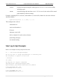
Shell command to load the carrier driver in st.cmd
In IOC application start up script, the carrier driver needs to be loaded before any IP drivers can be
loaded. This is done by the carrier driver configuration shell command. Clearly different architecture
uses different driver subsequently different configuration command.
For 8002/8003/8004 VME carrier with VxWorks or RTEMS
The carrier configuration command is
IPAC0=ipacAddHy8002(const char * “cardParam”)
The parameter string (cardParams) should comprise two (2) to six (6) parameters which are comma
separated. The first two are mandatory and have to be separated only by one comma. The others are
key/value pairs and are optional. The format is defined as
s,i,IPMEM=d,IPCLCK=d,ROAK=d,MEMOFFS=d
where d -- is a decimal integer number.
s -- defines the VME slot number of the carrier card. Valid number is 2 ~ 21. This number
MUST be the same as the VME slot number where the carrier card is plugged in.
i -- defines the interrupt level. Valid number is 0 ~ 7.
IPMEM=d -- defines the maximum memory size of the IP module. The valid values are 1, 2,
4 or 8 that represent 1MB, 2MB, 4MB or 8MB respectively. Default is 1. For majority Hytec
ADCs, DACs such as 8401, 8414, 8417, 8402 and 8415 etc, they all have 2MB on board. The
user can choose to use either 1MB or 2MB. None of the Hytec IPs has more than 2MB on
board memory. Other vendors might have.
IPCLCK=d -- defines the clock that its value has to be either 8 for 8MHz or 32 for 32Mhz.
Default is 8.
ROAK=d -- if d =1, it defines carrier card to release the interrupt upon the acknowledgment.
If d=0, the interrupt is released by user interrupt service routine. Default is 0.
MEMOFFS=d -- this parameter defines the VME end A32 memory access base address. "d"
is a decimal number that represents the offset (the upper WORD) of the VME end A32 base
address. It is needed when any of the two statements below is true:
Issue 12
Page 23 of 205
Hytec Electronics Ltd
Hytec EPICS Driver User Manual
DRV/2011/EPICS
A. The operating system either VxWorks or RTEMS has defined a non-zero
VME_A32_MSTR_BUS macro in the system config.h file.
B. The VME crate is not geographical addressing facilitated. In such a system,
user must use this to set up the VME base address for A32.
For a VME crate that is geographical addressing facilitated, and the system defines a
non-zero VME_A32_MSTR_BUS macro, then it is needed. But if
VME_A32_MSTR_BUS macro is defined as 0, then this is optional. Setting this the
driver will turn off the carrier card geographical addressing by setting a bit in the
CSR.
Note: MEMOFFS has nothing to do with A16 base address formation. A16 base
address is determined either by geographical addressing or by carrier board on board
jumper settings. For VME crate that is not geographical addressing facilitated, both
8002 and 8004 carriers need to use on board jumpers (J6~J10) to set up (On 8004
carrier, moving the jumpers to "manual" positions). When the VME crate is
geographical addressing facilitated, for 8002 carrier, A16 base address is determined
by the crate geographical addressing facility, i.e. determined automatically by the slot
number where the carrier is plugged in (the actually A16 base address is determined as
vmeslotnumber << 11). But for 8004 carrier, user can have a choice to either use the
on board jumpers to manually set up (moving jumpers J6~J10 away from "auto" to
"manual" positions) or let the geographical addressing to determine it (keep all J6 ~
J10 to "auto" position).
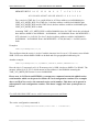
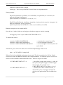
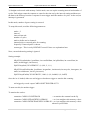
Calculation of MEMOFFS:
As mentioned above, MEMOFFS setting represents the upper WORD of A32 VME address.
Few things need to be considered when doing the calculation: IPMEM setting and the
VME_A32_MSTR_BUS and VME_A32_MSTR_SIZE macros definition in the config.h file
of the BSP.
IPMEM defines the memory size per IP card. Either 8002 or 8004 has up to 4 IPs so the
carrier memory size is 4 times of the IP memory. The minimum size of an IP which is also the
default setting (if IPMEM is not defined) is 1MB. Hence the MEMOFFS should start from
address line A22 as shown below
MEMOFFS BIT 15 14
13 12
11
10
9
8
7
6
5 4 3 2 1 0
A31 A30 A29 A28 A27 A26 A25 A24 A23 A22 0 0 0 0 0 0
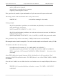
The MEMOFFS must be defined such that any two carriers in the same crate shouldn't have
overlapped memory area. So when IPMEM changes, the starting address line for calculating
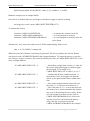
MEMOFFS changes as well as illustrated below:
Issue 12
Page 24 of 205
Hytec Electronics Ltd
Hytec EPICS Driver User Manual
IPMEM
1
2
4
8
DRV/2011/EPICS
memory per IP
carrier memory size
starting address line
1MB
2MB
4MB
8MB
4MB
8MB
16MB
32MB
A22
A23
A24
A25
all address lines below this bit must be 0.
The MEMOFFS calculation also needs to take VME_A32_MSTR_BUS and
VME_A32_MSTR_SIZE macros into account. These macros are defined in the BSP config.h
file. VME_A32_MSTR_BUS is the start address of VME end defined by the BSP and
VME_A32_MSTR_SIZE is the valid size of VME memory.
As such, the definition of MEMOFFS must be in the range between VME_A32_MSTR_BUS
~ VME_A32_MSTR_BUS + VME_A32_MSTR_SIZE. Otherwise the BSP range check will
reject the A32 base address register. The user will see an error during the IOC boot time
saying that the ipacAddHy8002 returned an error.
In principle, calculating MEMOFFS doesn't have to correspond it to VME slot number that
the carrier is plugged in. The only thing matters is as said that any two MEMOFFS settings
for any two carriers in the same crate should not overlap. Yet associating the VME slot
number in the calculation just makes better logical sense and fits the natural of human being's
thinking. Some examples are shown below.
Let's assume IPMEM=1 (the default setting), this gives 4MB memory space for a 8002 carrier
so starting address line is A22. The remaining must be 0.
MEMOFFS BIT 15 14
13
12
11
10
9
8
7
6
5 4 3 2 1 0
A31 A30 A29 A28 A27 A26 A25 A24 A23 A22 0 0 0 0 0 0
For a carrier in VME slot 2, we can define its A32 base address as 0x00400000, plus
VME_A32_MSTR_BUS. For VME slot 3, it could be 0x00800000 plus
VME_A32_MSTR_BUS and for VME slot 4, it could be 0x00C00000 plus
VME_A32_MSTR_BUS and so forth.
Assuming VME_A32_MSTR_BUS is 0x20000000, then for VME slot 4, the calculated base
address should be 0x00C00000 + 0x20000000 = 0x20C000000. Hence the MEMOFFS =
8384 (decimal, i.e. 0x20C0). For slot 5, the derived base address could be 0x01000000 +
0x20000000 = 0x21000000. Hence the MEMOFFS = 8448 (decimal, i.e. 0x2100) and so
forth.
Now if IPMEM=2, this gives 8MB memory space for each 8002 carrier so the starting
address line is A23. The remaining must be 0.
Issue 12
Page 25 of 205
Hytec Electronics Ltd
Hytec EPICS Driver User Manual
MEMOFFS BIT 15 14
13
12
11
10
9
8
7
DRV/2011/EPICS
6 5 4 3 2 1 0
A31 A30 A29 A28 A27 A26 A25 A24 A23 0 0 0 0 0 0 0
For a carrier in VME slot 2, we could define its A32 base address as 0x00800000 plus
VME_A32_MSTR_BUS. For VME slot 3, the base address could be 0x01000000 plus
VME_A32_MSTR_BUS and for VME slot 4, the base address could be 0x01800000 plus
VME_A32_MSTR_BUS so forth.
Assuming VME_A32_MSTR_BUS is still 0x20000000, then for VME slot 4, the calculated
base address should be 0x01800000 + 0x20000000 = 0x218000000. Hence the MEMOFFS =
8576 (decimal, i.e. 0x2180). For slot 5, the derived base address could be 0x02000000 +
0x20000000 = 0x22000000. Hence the MEMOFFS = 8704 (decimal, i.e. 0x2200) and so
forth.
Examples:
IPAC0=ipacAddHy8002("3,2")
This configures that the carrier is in slot 3 and the interrupt level is set to 2. IP memory uses default
1MB. Clock uses default 8MHz. RORA as default and uses geographical addressing etc.
Another example:
IPAC0=ipacAddHy8002("5,4,IPMEM=2,IPCLCK=8,ROAK=1,MEMOFFS=512 ")
Here the slot is 5, interrupt level is 4. IP memory size is 1MB, clock uses 8MHz. Use ROAK. The
memory offset for A32 is 512 which means its base address is 0x02000000 assuming the
VME_A32_MSTR_BUS macro is set to 0x00000000.
Please note, in VxWorks and RTEMS, ipacAddHy8002 command returns the added carrier
serial number which can be passed to further IP card configuration routines. The examples
above use IPAC0 to receive the returned carrier serial number. This then can be passed to
subsequent IP card configuration routines. This doesn’t apply for Linux system please see
below.
For 8002/8003/8004 VME carrier with Concurrent processor and Linux
The carrier configuration command is
IPAC0=ipacAddHy8002Concurrent(const char * “cardParam”)
Issue 12
Page 26 of 205
Hytec Electronics Ltd
Hytec EPICS Driver User Manual
DRV/2011/EPICS
The “cardParam” setting is exactly the same as ipacAddHy8002.
For 8001 VME carrier with VxWorks and RTEMS
The carrier configuration command is
IPAC0=ipacAddHy8001(const char * “cardParam”)
The “cardParam” setting is as follow
The parameter "cardParams" is a string that should comprise 2 (the first two are mandatory)
to 6 parameters that are separated by commas.
- first parameter is the VME slot number (decimal string)
- second parameter is the VME interrupt level (decimal string)
- third parameter is a name/value pair defines the type of releasing interrupt. "ROAK=1" means to
release interrupt upon acknowledgement; "ROAK=0" means to release by ISR.
- fourth parameter defines IP memory mapping base address offset when neither geographical
addressing nor jumpers are used. "MEMOFFS=128". Please refer to ipacAddHy8002.
For IOC90101, 6335, 7002/7003 under Linux
The configuration shell command is
ipacAddHyLinux9010(char * cardParam)
The parameter string (cardParams) should comprise two (2) to six (6) parameters which are comma
separated. The first two are mandate and have to be separated only by one comma.
The others are key/value pairs and are optional. The format is defined as
s,i,IPCLCKA=8,IPCLCKB=8,IPCLCKC=8,IPCLCKD=32,IPCLCKE=32,IPCLCKF=32
Where:
s -- The ID number of the carrier card mentioned in PCI device driver in Chapter 2 for
multiple carrier system such as 6335 or 7002/7003. This ID number is set by the on board
jumpers that give the carrier ID number from 0 to 31. For a single carrier such as IOC9010
blade, it is set to 99.
i -- It is not used. Normally set it to 0.
Issue 12
Page 27 of 205
Hytec Electronics Ltd
Hytec EPICS Driver User Manual
DRV/2011/EPICS
IPCLCKA ~ IPCLCKF - Defines IP slot (A ~ F) frequencies. They are name/value pairs.
The value number can only be either 8 or 32 that represent 8MHz or 32MHz respectively.
These name/value pairs are optional. If a slot doesn't have the correspondent name/value pair,
it defaults to 8MHz.
Examples:
For IOC9010 blade that uses Linux operating system
ipacAddHyLinux9010("99,0")
This configures a single carrier system with all IP slots set to 8MHz.
For Hytec 6335 or 7002 carrier card
ipacAddHyLinux9010("2,0")
ipacAddHyLinux9010("3,0")
This configures a multiple carrier system with one carrier ID set to 2 and the other set to 3 by their on
board jumpers.
Note, under Linux we cannot define variables in the shell command to receive the returning
carrier serial number then pass it to the subsequent IP configuration routines. As such we need
to manually maintain the serial number. For example
ipacAddHyLinux9010("2,0")
ipacAddHyLinux9010("3,0")
will add two carriers in the system. The first one the carrier serial number will be 0 and the second
one will be 1 and so forth. These numbers then can be passed to the subsequent IP configuration
routines who sit on these carrier cards.
For IOC9010 with RTEMS operating system
The configuration shell command is
ipacAddHyRTEMS9010(char *cardParams)
The parameter "cardParams" is a string that should comprise at least 3 to 9 parameters with comma
separated without space. The first three are the carrier card PCI addresses, i.e. bus, device, function.
The remaining 6 are name/value pair optional parameters that define each IP card clock. If they are
not defined, 8MHz is the default clock. But the last 6 parameters are only for IOC9010 blade at the
moment. The parameters format is
Issue 12
Page 28 of 205
Hytec Electronics Ltd
Hytec EPICS Driver User Manual
DRV/2011/EPICS
b,d,f,IPCLCKA=8,IPCLCKB=8,IPCLCKC=8,IPCLCKD=32,IPCLCKE=32,IPCLCKF=32
where:
b -- bus address of the PCI device
d -- device address of the PCI device.
f -- function number of the PCI device.
IPCLCKA ~ IPCLCKF - Defines IP slot (A ~ F) frequencies. The number of each
paramater can only be either 8 or 32 that represent 8MHz or 32MHz respectively. These
name/value pairs are optional. If a slot doesn't have the correspondent name/value pair, it
defaults to 8MHz. NOTE, these settings only apply to IOC9010 blade.
Note, to find out the PCI device addresses, in Linux do command
lspci
which will list all the PCI devices in the system. Try to find 9010, 7002 or 6335 for Hytec devices
and on the left of a device entry shows the PCI address such as
01:04.0
This means, the PCI device bus=1, device=4 and function=0.
Examples:
IPAC1=ipacAddHyRTEMS9010("1,4,0,IPCLCKA=8,IPCLCKB=32,IPCLCF=8")
This configuration indicates the IOC9010 carrier PCI addresses are bus=1, device=4 and function=0;
IP slot A, F use 8MHz, slot B as 32MHz. Others use default 8MHz.
Issue 12
Page 29 of 205
Hytec Electronics Ltd
Hytec EPICS Driver User Manual
DRV/2011/EPICS
4. Start up Script
The start up script is slightly different in different operating systems and architectures. The main
differences lie on the beginning part of the script that loads the IOC application executable. The dbd
file, carrier card configuring, IP card configuring and databases loading are almost the same.
Linux IOC
Linux IOC usually has the top part start up script something like this, providing the environment path
definition file envPaths exists.
#!../../bin/linux-x86/example
< envPaths
cd ${TOP}
The envPaths file is automatically generated in the IOC boot directory and defines several
environment variables that are useful later in the start up script. To be able to create this envPaths file
under Linux, we need to change the ARCH variable value in the Makefile under
<exampleTop>/iocBoot/iocBootexample to this (in red):
TOP = ../..
include $(TOP)/configure/CONFIG
ARCH = linux-x86
TARGET = envPaths
include $(TOP)/configure/RULES.ioc
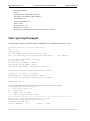
Below is an example of the Hy8417 IP card asyn driver testing script.
epicsEnvSet("ARCH","linux-x86")
epicsEnvSet("IOC","iocexample")
epicsEnvSet("TOP","/home/hytec/linux/work/R3.14.11/Hy8417ip-asyn/23/example")
epicsEnvSet("SUPPORT","/home/hytec/linux/prod/R3.14.11/")
epicsEnvSet("IPAC","/home/hytec/linux/prod/R3.14.11/ipac/ipac-2.11")
epicsEnvSet("HY8417IP","/home/hytec/linux/work/R3.14.11/Hy8417ip-asyn/23/example/..")
epicsEnvSet("EPICS_BASE","/home/EPICS/R3.14.11/base")
VxWorks IOC
VxWorks IOC usually has the following top part of the start up script.
Issue 12
Page 30 of 205
Hytec Electronics Ltd
Hytec EPICS Driver User Manual
DRV/2011/EPICS
#!$(INSTALL)/bin/vxWorks-ppc604_long/example
cd "/dls_sw/work/R3.14.8.2/support/Hy8417ip-asyn/2-3/example"
ld < bin/vxWorks-ppc604_long/example.munch
In VxWorks, after the build, it creates a .munch file which is the executable of the target.
RTEMS IOC
RTEMS IOC usually has the following top part of the start up script.
iocBoot=pwd()
cd("../..")
ld( "bin/RTEMS-mvme5500/example.obj")
RTEMS doesn’t generate the munch file. It creates either the executable “example” and “example.boot” files or the
“.obj” file.
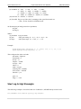
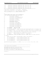
The Common Part
The common part is almost the same for any operating systems. Below is an example of Hy8417
module testing script.
epicsEnvSet(EPICS_CA_MAX_ARRAY_BYTES,"3000000")
## Register all support components
dbLoadDatabase("dbd/example.dbd")
example_registerRecordDeviceDriver(pdbbase)
#Carrier module
# For PCI/Linux IOC, use
ipacAddHyLinux9010("99,1")
# For PCI/RTEMS IOC, use
#ipacAddHyRTEMS9010("1,4,0")
# For VME/VxWorks
#IPAC3 = ipacAddHy8002("3,2")
Issue 12
Page 31 of 205
Hytec Electronics Ltd
Hytec EPICS Driver User Manual
DRV/2011/EPICS
#int Hy8417AsynInit(char *portName, "ADC8417"
# int carrierNum,
0
# int ipSlotNum,
0
# int vectorNum,
88
# int mode)
0 (continuous)
Hy8417AsynInit("ADC8417", 0, 0, 88, 0)
#int Hy8417AsynExtInit(char *portName, "ADC8417"
# int samples,
10000
# int average,
1000
# int offset,
0
# int clockRate,
9 (1kHz)
# int extClock,
0 (internal)
# int fastADC,
1 (fast ADC, not for mca & EPID)
# int range,
0 (+/-10V)
# int ChannelNo,
16
# int ChannelBit) 24
Hy8417AsynExtInit("ADC8417", 10000, 1, 0, 9, 0, 1, 0, 16, 24)
# int initFastSweep(char *portName, char *inputName,
#
int maxSignals, int maxPoints)
# portName
= asyn port name for this port
# inputName = name of input port
# maxSignals = maximum number of input signals.
# maxPoints = maximum number of points in a sweep. The amount of memory
#
allocated will be maxPoints*maxSignals*4 bytes
#$(VXWORKS_ONLY)initFastSweep("8417Sweep1","ADC8417", 16, 10000)
##########
# Hytec 8402 DAC in IP site B of the IP carrier card in slot 10.
#$(VXWORKS_ONLY)Hy8402ipConfigure (302, IPAC3, 2, 11)
#initHy8402ipAsyn("DAC", 302)
##########
## Load record instances
dbLoadRecords("db/example.db","P=CARD1,PORT=ADC8417")
#dbLoadRecords("db/examplemca.db")
#dbLoadRecords("db/exampleepid.db")
# set trace output level for asyn port "ADC8417"
# Level: 0x01 = Errors only
# asynSetTraceMask arguments:
# * asyn port
# * address of that asynport (i.e. channel number)
# * verbosity level:
#
0x01: error,
#
0x11: errors, warnings and debug
#
0x00: silent
asynSetTraceMask( "ADC8417", 0, 0x00 )
# all driver level messages
iocInit()
Issue 12
Page 32 of 205
Hytec Electronics Ltd
Hytec EPICS Driver User Manual
DRV/2011/EPICS
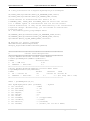
Please note, sometimes (and sometimes not, I don’t know why, this remains a mystery to me)
VxWorks shell command complains that the arguments of a single function call should not
exceeded 10. So any configuration routine that has more than 10 parameters would get an
error when loading the start up script. To get around this, add
iocsh()
before the configuration routine. This change the VxWorks shell configuration routine to IOC
shell and the IOC shell doesn’t have the limitation of 10 parameters.
Issue 12
Page 33 of 205
Hytec Electronics Ltd
Hytec EPICS Driver User Manual
DRV/2011/EPICS
5. Set up RTEMS IOC application loading for
IOC9010
Note, this part is for building IOCs on IOC9010 blade with RTEMS operating system only.
After building EPICS application successfully on IOC9010 blade with RTEMS operating system, the
next step is how to load the RTEMS image and run the EPICS start script.
There are many approaches of doing this such as network PXE boot, DHCP and BOOTP server or
NFTS etc. Below details a method we have been using at Hytec which utilises GRUB for loading the
RTEMS image and Windows DHCP and BOOTP server for loading the IOC.
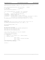
Building the IOC application
Building an IOC application includes the following steps but it is not the main discussion here. Please
refer to documents listed in the reference and all other chapters.
-
Install EPICS core
Install RTEMS
Install network support module such as libbsdport for IOC9010 PC104 processor
Install other support modules such as IPAC, asyn etc
Install IP drivers
Create the application
Build application
After finishing all the steps above we will have a RTEMS image built in the application
<TOP>/bin/RTEMS-pc586 folder. Taking Hytec 8506 as an example, after the build we get an image
named
Hy8506example
Set up loading RTEMS image
On IOC9010, we have Scientific Linux installed hence we have the grub loader by default. We can
utilise the grub loader to load our RTEMS IOC image.
Issue 12
Page 34 of 205
Hytec Electronics Ltd
-
Hytec EPICS Driver User Manual
DRV/2011/EPICS
Copy the image file "Hy8506example" from Hy8506/2.0/example/bin/RTEMS-pc586 to /boot
directory
Modify /etc/grub.conf file to add two lines in red for loading rtems Hy8506example
# grub.conf generated by anaconda
#
# Note that you do not have to rerun grub after making changes to this file
# NOTICE: You have a /boot partition. This means that
#
all kernel and initrd paths are relative to /boot/, eg.
#
root (hd0,0)
#
kernel /vmlinuz-version ro root=/dev/VolGroup00/LogVol00
#
initrd /initrd-version.img
#boot=/dev/sda
default=0
timeout=5
splashimage=(hd0,0)/grub/splash.xpm.gz
hiddenmenu
title Scientific Linux (2.6.18-194.3.1.el5)
root (hd0,0)
kernel /vmlinuz-2.6.18-194.3.1.el5 ro root=/dev/VolGroup00/LogVol00 rhgb
quiet
initrd /initrd-2.6.18-194.3.1.el5.img
#########add the following two lines#######
title Hy8506
kernel /Hy8506example
###########################################
title Other
rootnoverify (hd1,0)
chainloader +1
This will cause the Linux box during the boot time to display a message asking "Press any key to
enter the menu...", and display all loadable operating systems. As to the above example, the menu
will show:
Scientific Linux (2.6.18-194.3.1.el5)
Hy8506
Then use the arrow key to choose which operating system to load.
You might want to change the timeout=5 to longer seconds say 30 for example in order not to miss
hitting the key.
Also, you can move these two lines above the "title Scientific Linux (2.6.18-194.3.1.el5) which will
load your rtems app by default if you don't hit any key after the timeout elapse. This is useful when
you want it to run straight away to the rtems app.
Set up DHCP and BOOTP server for loading EPICS
Issue 12
Page 35 of 205
Hytec Electronics Ltd
Hytec EPICS Driver User Manual
DRV/2011/EPICS
At Hytec the corporate network uses Windows 2003 server which has both DHCP and BOOTP
server hence we just use them for our EPICS application loading.
-
-
Find BOOTP root directory on the server, create a directory named "ioc001" (you might want
to check this name defined in the rtems_netconfig.c file under EPICS/base-3-1411/src/RTEMS/base in the "struct rtems_bsdnet_config rtems_bsdnet_config" structure
definition)
In the "ioc001" folder, create a subdirectory named "epics"
Copy db and dbd directory from your application such as Hy8506/2.0/example in the case of
the above example from the blade to the BOOTP server root/ioc001/epics directory
Copy st.cmd from IOC9010 Hy8506/2.0/example/iocBoot/iocHy8506example to the BOOTP
server root/ioc001/epics directory
Start the IOC
Once the setup has been done, we can run the IOC now.
-
Reboot IOC9010 blade
When you see the boot flash
Press any key to enter the menu
Boot Scientific Linux (2.6.18-194.3.1.e15) in xx seconds...
-
Hit any key to enter the menu
Then select Hy8506. This will boot the RTEMS build first and then try to get an IP address
from the DHCP server and then start the TFTP client to get st.cmd from the BOOTP server. If
everything is set up properly, the rtems should start, and EPICS and st.cmd will be loaded to
run the example application.
Issue 12
Page 36 of 205
Hytec Electronics Ltd
Hytec EPICS Driver User Manual
DRV/2011/EPICS
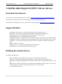
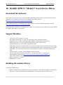
6. Hy8505 16bit Digital IO EPICS Device Driver
Download the Software
The software can be downloaded from Hytec website http://www.hytec-electronics.co.uk/Download.aspx .
The hardware user manual can also be downloaded from the same website page above.
Any problems downloading the software, please contact Hytec support at [email protected] .
Support Modules
-
-
ipac module version ipac-2.11 plus one of the Hytec carrier card drivers such as
drvHy8002.c for VxWorks or RTEMS under VME64x with 8002/8003/8004 carriers,
drvHyLinuxCarrier.c for Linux with IOC9010/PCIe6335/uTCA7002 carriers,
drvHyRTEMSCarrier.c for RTEMS with IOC9010 blade.
drvHy8002Concurrent.c for 8002 VME carrier when used with Concurrent processor board in Linux
drvHyMrfConcurrent.c for Micro Research VME Module when used with Concurrent CPU in Linux
drvHy8001.c is used for 8001 VME carrier and IO board for VxWorks or RTEMS with Motorola
CPU
EPICS core R3.14.8.2 or later.
devlib2 version 2.1 or later if porting RTEMS on IOC9010 blade
RTEMS R4.9.4 or later if RTEMS is the operating system.
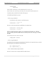
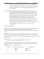
Building the module library
To build the module library,
-
Before building the 8505 module, the ipac driver has to be built successfully first.
If the IOC is built on IOC9010 blade with RTEMS, devLib2 module has to be built as well.
Modify EPICS_BASE and SUPPORT environment variables in the configure/RELEASE file to your
site
Make sure the CONFIG_SITE.linux-x86.Common file under EPICS_BASE/configure/os has proper
target architecture set, the cross compiler if the build is not for Linux itself.
At <TOP> folder, do make.
Issue 12
Page 37 of 205
Hytec Electronics Ltd
Hytec EPICS Driver User Manual
DRV/2011/EPICS
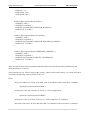
Configuration of the Carrier Card
Please refer to chapter 3 for detail installation.
Database definition file
Database definition file is: Hy8505.dbd which is located in the src of the module.
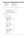
Testing Database(s)
There are a few testing databases in the example/Hy8505exampleApp/Db folder. They are
Hy8505-II-bi.db
Hy8505-OO.db
Hy8505-II-mbbi.db
As they are named, the first one is for input; second one is for output and one last for mbbi records.
Building an Example Application
To build an example to test the 8505 driver, use EPICS makeBaseApp.pl script to create the example as usual.
Then modify the following files to include the driver module(s). Alternatively you can just test the driver by
using the example included in the module package.
- example <TOP>/configure/RELEASE
Change the EPICS_BASE and SUPPORT to the proper directories.
Add IPAC moudle:
IPAC=$(SUPPORT)/ipac/ipac-2.11
HY8505IP=$(TOP)/..
If the IOC is built on IOC9010 blade with RTEMS, also add this line
EPICSPCI=$(SUPPORT)/devlib2-2.0
Issue 12
Page 38 of 205
Hytec Electronics Ltd
Hytec EPICS Driver User Manual
DRV/2011/EPICS
If the system uses Concurrent VME processor under Linux operating system, the Concurrent device
driver and API function module needs to be added. This module can be placed in the SUPPORT
directory a structure similar to:
cctvmeen/include
/lib/linux-x86
In the “include” sub-directory, it is the include header file: vme_api_en.h
In the “lib/linux-x86” sub-directory is the library files: libcctvmeen.a and libvmedriver26.a
To add this module in the RELEASE, add the following line:
CCTVMEEN=$(SUPPORT)/cctvmeen
- <TOP>xxxApp/src/Makefile
In the Makefile of the example src, add following lines:
example_DBD += drvIpac.dbd
example_LIBS += Ipac
If the IOC is built on IOC9010 blade with RTEMS, also add these lines
example_DBD += epicspci.dbd
example_DBD += epicsvme.dbd
example_LIBS += epicspci
NOTE: to include this epicsvme appears to be a bit odd since IOC9010 is not a VME but
because it defines pdevLibVirtualOS, which is needed by devlib.c due to the legacy, it satisfies
the build.
If Conccurent processor for Linux is used, add
example_LIBS += cctvmeen
- <TOP>/xxxApp/Db/Makefile
Copy Hy8505-II-bi.db, Hy8505-OO.db and Hy8505-II-mbbi.db to the example Db directory and add
the following lines in the Makefile of that directory:
DB += Hy8505-II-bi.db
DB += Hy8505-OO.db
DB += Hy8505-II-mbbi.db
- <TOP>/ iocBoot/iocBootexample /Makefile
Issue 12
Page 39 of 205
Hytec Electronics Ltd
Hytec EPICS Driver User Manual
DRV/2011/EPICS
If the IOC is built for Linux, modify the ARCH variable value to
ARCH = linux-x86
Also make sure the envPath file in iocBoot/iocexample directory is properly set up.
- Build the application from the example <TOP>
- Modify st.cmd in iocBoot/iocexample as per next section and run the start up script from here.
Configuration Shell Command for Start up Script
There are two configuration shell functions to set up the 8505, Hy8505Configure and
Hy8505ExtraConfig
int Hy8505Configure(int cardnum, int carrier, int ipslot, int debrate, int pwidth, int scanrate,
int dir, int intr, int clock)
where:
cardnum
carrier
ipslot
debrate
EPICS card number (Defined by the user to identify the card)
carrier serial number as discussed in chapter 3 of carrier drivers.
ipslot 0-3
debounce rate 0 = none
1 = 100Hz
2 = 200Hz
3 = 500Hz
4 = 1kHz
pwidth
pulse width
scanrate
dir
Issue 12
0 = 1 msec
1 = 10 msec
2 = 100 msec
3 = 1 sec
4 = 2 sec
5 = 5 sec
6 = 10 sec
7 = 20 sec
8 = 50 sec
9 = 100 sec
input scan rate 0 = 1kHz
1 = 10kHz
2 = 100kHz
3 = 1MHz
0 = inputs
Page 40 of 205
Hytec Electronics Ltd
Hytec EPICS Driver User Manual
DRV/2011/EPICS
1 = low outputs / high inputs
2 = low inputs / high outputs
3 outputs
Bits 2 & 3 (values 4 and 8, respectively) encode whether the input
and output values should be inverted.
(dir & 4) == 4 => Invert all input bits
(dir & 8) == 8 => Invert all output bits
intr
clock
interrupt vector
0 = internal, 1 = external
The second configuration function
Hy8505ExtraConfig(int cardnum, int debmask, int pmask, int intmask)
Where:
cardnum
debmask
pmask
intmask
card number, same as above, 71 for example.
debounce mask. Defines which bit (if set) needs to be debounced. For inputs
only.
pulse/level mask. Defines which bit is a pulse output (1) or level output (0).
For outputs only.
interrupt mask bit. Defines which input bit (if set) state change would cause
interrupt. For inputs only
Start up Script Example
The example script below is the start up for loading the example IOC in IOC9010 blade with Linux operating
system.
#!../../bin/linux-x86/Hy8505example
< envPaths
cd ${TOP}
## Register all support components
dbLoadDatabase "dbd/Hy8505example.dbd"
Hy8505example_registerRecordDeviceDriver pdbbase
# For PCI/Linux IOC, use
ipacAddHyLinux9010("99,1")
# For PCI/RTEMS IOC, use
#ipacAddHyRTEMS9010("1,4,0")
# For VME/VxWorks
#IPAC3 = ipacAddHy8002("3,2")
Issue 12
Page 41 of 205
Hytec Electronics Ltd
Hytec EPICS Driver User Manual
DRV/2011/EPICS
# Hy8505Configure(cardnum, carrier, ipslot, debrate,
#
pwidth, scanrate, dir, intr, clock)
Hy8505Configure(71, 0, 2, 4, 3, 0, 0, 0x88, 0)
# Hy8505ExtraConfig(cardnum, debmask, pmask, intmask)
Hy8505ExtraConfig(71, 0xFFFF, 0x0, 0xFFFF)
## Load record instances
dbLoadRecords "db/Hy8505-II-bi.db", "device=DIO"
dbLoadRecords "db/Hy8505-II-mbbi.db", "device=DIO"
dbLoadRecords "db/Hy8505-OO.db", "device=DIO"
cd ${TOP}/iocBoot/${IOC}
iocInit
Issue 12
Page 42 of 205
Hytec Electronics Ltd
Hytec EPICS Driver User Manual
DRV/2011/EPICS
7. Hy8506 48bit Digital IO EPICS Device Driver
Download the Software
The software can be downloaded from Hytec website http://www.hytec-electronics.co.uk/Download.aspx .
The hardware user manual can also be downloaded from the same website page above.
Any problems downloading the software, please contact Hytec support at [email protected] .
Support Modules
-
-
ipac module version ipac-2.11 plus one of the Hytec carrier card drivers such as
drvHy8002.c for VxWorks or RTEMS under VME64x with 8002/8003/8004 carriers,
drvHyLinuxCarrier.c for Linux with IOC9010/PCIe6335/uTCA7002 carriers,
drvHyRTEMSCarrier.c for RTEMS with IOC9010 blade.
drvHy8002Concurrent.c for 8002 VME carrier when used with Concurrent processor board in Linux
drvHyMrfConcurrent.c for Micro Research VME Module when used with Concurrent CPU in Linux
drvHy8001.c is used for 8001 VME carrier and IO board for VxWorks or RTEMS with Motorola
CPU
EPICS core R3.14.8.2 or later.
devlib2 version 2.1 or later if porting RTEMS on IOC9010 blade
RTEMS R4.9.4 or later if RTEMS is the operating system.
Building the module library
To build the module library,
-
Before building the 8506 module, the ipac driver has to be built successfully first.
If the IOC is built on IOC9010 blade with RTEMS, devLib2 module has to be built as well.
Modify EPICS_BASE and SUPPORT environment variables in the configure/RELEASE file to your
site
Make sure the CONFIG_SITE.linux-x86.Common file under EPICS_BASE/configure/os has proper
target architecture set, the cross compiler if the build is not for Linux itself.
At <TOP> folder, do make.
Issue 12
Page 43 of 205
Hytec Electronics Ltd
Hytec EPICS Driver User Manual
DRV/2011/EPICS
Configuration of the Carrier Card
Please refer to chapter 3 for detail installation.
Database definition file
Database definition file is: Hy8506.dbd which is located in the src of the module.
Testing Database(s)
There are a few testing databases in the example/Hy8506exampleApp/Db folder. They are
Hy8506-II-bi.db
Hy8506-OO.db
Hy8506-II-mbbi.db
Building an Example Application
To build an example to test the 8506 driver, please use EPICS makeBaseApp.pl script to create the example as
usual. Then modify the following files to include the driver module(s). Alternatively you can just test the
driver by using the example included in the module package.
- example <TOP>/configure/RELEASE
Change the EPICS_BASE and SUPPORT to the proper directories.
Add IPAC module:
IPAC=$(SUPPORT)/ipac/ipac-2.11
HY8506IP=$(TOP)/..
If the IOC is built on IOC9010 blade with RTEMS, also add this line
EPICSPCI=$(SUPPORT)/devlib2-2.0
If the system uses Concurrent VME processor under Linux operating system, the Concurrent device
driver and API function module needs to be added. This module can be placed in the SUPPORT
directory a structure similar to:
Issue 12
Page 44 of 205
Hytec Electronics Ltd
Hytec EPICS Driver User Manual
DRV/2011/EPICS
cctvmeen/include
/lib/linux-x86
In the “include” sub-directory, it is the include header file: vme_api_en.h
In the “lib/linux-x86” sub-directory is the library files: libcctvmeen.a and libvmedriver26.a
To add this module in the RELEASE, add the following line:
CCTVMEEN=$(SUPPORT)/cctvmeen
- <TOP>xxxApp/src/Makefile
In the Makefile of the example src, add following lines:
example_DBD += drvIpac.dbd
example_LIBS += Ipac
If the IOC is built on IOC9010 blade with RTEMS, also add these lines
example_DBD += epicspci.dbd
example_DBD += epicsvme.dbd
example_LIBS += epicspci
NOTE: to include this epicsvme appears to be a bit odd since IOC9010 is not a VME but
because it defines pdevLibVirtualOS which is needed by devlib.c due to the legacy, it satisfies
the build.
If Conccurent processor for Linux is used, add
example_LIBS += cctvmeen
- <TOP>/xxxApp/Db/Makefile
Copy Hy8506-II-bi.db, Hy8506-OO.db and Hy8506-II-mbbi.db to the example Db directory and add
the following lines in the Makefile of the that directory:
DB += Hy8506-II-bi.db
DB += Hy8506-OO.db
DB += Hy8506-II-mbbi.db
- <TOP>/ iocBoot/iocBootexample /Makefile
If the IOC is built for Linux, modify the ARCH variable value to
Issue 12
Page 45 of 205
Hytec Electronics Ltd
Hytec EPICS Driver User Manual
DRV/2011/EPICS
ARCH = linux-x86
Also make sure the envPath file in iocBoot/iocexample directory is properly set up.
- Build the example application from <TOP>
- Modify st.cmd in iocBoot/iocexample as per next section and run the start up script from here.
Configuration Shell Commands for Start up Script
There are two configuration shell commands to set up 8506. The first one is to set up the IP card and the
second one is to set up the ports.
IP card configuration
Hy8506Configure(int cardnum, int carrier, int ipslot, int vector)
Where:
cardnum
carrier
ipslot
vector
EPICS card number (User defines)
carrier number returned by ipacAddxxxx
ipslot 0-5
interrupt vector
Port configuration
Hy8506PortConfig(int cardnum, int port, int debrate, int pwidth, int scanrate, int dir,
Int debmask, int pmask, int intmask)
Where:
cardnum
port
debrate
debmask
scanrate
dir
Issue 12
EPICS card number (User defines)
port number. must be 0, 1 or 2
debounce rate 0 = none
1 = 100Hz
2 = 200Hz
3 = 500Hz
4 = 1kHz
select input bits to debounce 0x0000 - 0xFFFF
input scan rate 0 = 1kHz
1 = 10kHz
2 = 100kHz
3 = 1MHz
bit0 = 0: all 16 channels as inputs
Page 46 of 205
Hytec Electronics Ltd
Hytec EPICS Driver User Manual
DRV/2011/EPICS
bit0 = 1: all 16 channels as outputs
intmask
pwidth
pmask
Bit1 encode whether the input or output
values should be inverted.
bit1 = 0: No inversion
bit1 = 1: Invert all input/output bits
select bits to generate interrupts 0x0000 - 0xFFFF
pulse width
0 = 1 msec
1 = 10 msec
2 = 100 msec
3 = 1 sec
4 = 2 sec
5 = 5 sec
6 = 10 sec
7 = 20 sec
8 = 50 sec
9 = 100 sec
select bits to pulse on output
0x0000 - 0xFFFF
Start up Script Example
Below is an strat up script for loading the RTEMS IOC with 8506 IP card.
#!../../bin/linux-x86/Hy8506example
dbLoadDatabase "dbd/Hy8506example.dbd"
Hy8506example_registerRecordDeviceDriver pdbbase
# For PCI/Linux IOC, use
#ipacAddHyLinux9010("99,1")
# For PCI/RTEMS IOC, use
ipacAddHyRTEMS9010("1,4,0")
# For VME/VxWorks
#IPAC3 = ipacAddHy8002("3,2")
# Hy8505Configure(cardnum, carrier, ipslot, vector)
Hy8506Configure(71, 0, 3, 0x88)
#Hy8506PortConfig(cardnum,
#
Hy8506PortConfig(71, 0, 4,
Hy8506PortConfig(71, 1, 4,
Hy8506PortConfig(71, 2, 4,
port, debrate, pwidth, scanrate, dir,
debmask, pmask, intmask)
3, 0, 0, 0xFFFF, 0x0, 0xFFFF)
3, 0, 1, 0xFFFF, 0x0, 0xFFFF)
3, 0, 3, 0xFFFF, 0x0, 0xFFFF)
dbLoadRecords "db/Hy8506-II-bi.db", "device=DIO"
dbLoadRecords "db/Hy8506-OO.db", "device=DIO"
dbLoadRecords "db/Hy8506-II-mbbi.db", "device=DIO"
Issue 12
Page 47 of 205
Hytec Electronics Ltd
Hytec EPICS Driver User Manual
DRV/2011/EPICS
cd ${TOP}/iocBoot/${IOC}
iocInit
Issue 12
Page 48 of 205
Hytec Electronics Ltd
Hytec EPICS Driver User Manual
DRV/2011/EPICS
8. Hy8515/8516 Serial Port Device Driver
General Information
There are two types of driver support for Hytec 8515/8516 serial devices.
One is to support EPICS IOC’s running on Linux boxes. This is provided with a Linux UART device
driver which converts the 8515/8516 to normal COM ports. The EPICS application can just use them
the same way of using the on board serial port ttyS0, ttyS1 etc. Please refer to chapter 2 for the
device driver installation.
If the system uses Concurrent VME processor with Linux, there is also a Linux uart device driver
associated to it. Loading this device driver would turn all ports on 8515 or 8516 to local tty ports.
They are named ttyHy1 ~ ttyHy15 for example.
The second one is at present only for VxWorks on VME architecture that is described in this chapter.
This driver was done by Paul Hamadyk [[email protected] ], Diamond Light Source.
Download the Software
The software can be downloaded from Hytec website http://www.hytec-electronics.co.uk/Download.aspx .
The hardware user manual can also be downloaded from the same website page above.
Any problems downloading the software, please contact Hytec support at [email protected] .
Support Modules
-
ipac module version ipac-2.11 plus 8002 carrier card drivers. Please consult Diamond Light Source to
get a copy.
EPICS core R3.14.8.2 or later.
Build the module library
To build the module library,
Issue 12
Page 49 of 205
Hytec Electronics Ltd
-
Hytec EPICS Driver User Manual
DRV/2011/EPICS
Before building the 8515/8516 module, the ipac driver has to be built successfully first.
Modify EPICS_BASE and SUPPORT environment variables in the configure/RELEASE file to your
site for Hytec 8515/8516 module
Make sure the CONFIG_SITE.linux-x86.Common file under EPICS_BASE/configure/os has proper
target architecture set, the cross compiler if the build is not for Linux itself.
At <TOP> folder, do make.
Configuration of the Carrier Card
Please refer to the comments in the carrier driver file.
Database definition file
Database definition file is: DLS8515.dbd which can be found in the src of the module. It contains:
function("DLS8515Configure")
function("DLS8516Configure")
function("DLS8515DevConfigure")
function("DLS8516DevConfigure")
function("DLS8515Display")
function("DLS8516Display")
variable(dls8515debug, int)
Building an Example Application
To build an example to test the 8515/8516 driver, use EPICS makeBaseApp.pl script to create the example as
usual. Then modify the following files to include the driver module(s).
-
example <TOP>/configure/RELEASE
Change the EPICS_BASE and SUPPORT to the proper directories.
Add calc, std and ipac modules:
IPAC=$(SUPPORT)/ipac/ipac-2.11
DLS8515IP=$(TOP)/..
-
<TOP>xxxApp/src/Makefile
In the Makefile of the example src, add following lines:
Issue 12
Page 50 of 205
Hytec Electronics Ltd
Hytec EPICS Driver User Manual
DRV/2011/EPICS
example_DBD += drvIpac.dbd
example_DBD += DLS8515.dbd
example_LIBS += Ipac
example_LIBS += DLS8515
-
Build the application from example <TOP>
-
Modify st.cmd in iocBoot/iocexample as per next section and run the start up script from here.
Configuration Shell Command for Start up Script
There are two sets configuration shell commands, one for configuring the IP module and one for configuring
the individual UART port.
Module configuration commands
int DLS8515Configure(int card, int carrier, int vector, char *prefix)
int DLS8516Configure(int card, int carrier, int vector, char *prefix)
where:
card
carrier
vector
poll
prefix
card number
10 * slot + IP
carrier number
value returned by ipacAddHy8002()
interrupt vector 192 - 255
polling period
1 - x, 0 for interrupts
device name prefix
UART configuration commands
int DLS8515DevConfigure(char *dev, int baud, int data, int stop, int
parity, int flow);
int DLS8516DevConfigure(char *dev, int baud, int data, int stop, int
parity, int flow, int tadelay, int duplex);
where:
*dev
baud
data
stop
parity
flow
tadelay
Issue 12
device name
baud rate. Valid value = 100, 400, 600, 1200, 2400, 4800, 9600, 19200, 38400, 57600,
76800, 115200, 153600, 230400, 460800, 921600
data bit could. Valid value = 5, 6, 7, 8
stop bit could. Valid value = 1, 2
parity check. Valid value = N, E, O
flow control. Valid value = N, S, H
half duplex changing over delay time. Valid value 0 ~ 15
Page 51 of 205
Hytec Electronics Ltd
duplex
Hytec EPICS Driver User Manual
DRV/2011/EPICS
full/half duplex. Valid value = 0, 1, where 0 for half duplex and 1 for full duplex.
Example:
DLS8515Configure(73, IPAC7, newInterruptVector(), "ab")
would configure the IP module in VME slot 7, IP slot D and create the vxWorks devices /ab/73/0 /ab/73/7
The individual channels can be configured with asynSetOption or DLS8515DevConfigure which has
the following syntax:
DLS8515DevConfigure("/ab/73/0", 57600, 7, 1, 'E', 'N')
Some notes
-
Use the command DLS8515Display(int level) with a level of 0 or 1 for some internal information and
statistics. This command spawns a low priority task so don't run it in your boot script.
-
Always uses interrupts for both sending and receiving data.
Uses a vxWorks buffer size of 256 for transmit and 32768 for receive.
Uses an RX FIFO trigger level of 56 and a TX FIFO trigger level of 1.
Creates a TX and RX process for each IP module.
Latches errors and prints a single message until acknowledged by the user.
Is not hot swappable.
There is also a DLS8516Configure command for 422/485 devices. The most important
difference between this driver and drvHy8515 is that in RS485 mode you always receive the
characters you transmit. It is up to the user to handle this in their StreamDevice protocol file.
This is a feature of the UART used on the Hytec IP module.
The DLS8516Configure command has two additional arguments; these are the "Auto RS485
Half Duplex Direction Control Delay From TX to RX" value in bit time (0-15) when using
the RTS# line, and the second is the full duplex (1) for RS422 or half duplex (0) for RS485.
If you have high data rates you will see a few "interrupt: bad vme interrupt 0" messages. The
8515/8516 appears to be a bit slow at de-asserting its interrupt request line so the IOC
sometimes thinks that there is a pending interrupt when it returns from the interrupt service
routine.
-
-
Issue 12
Page 52 of 205
Hytec Electronics Ltd
Hytec EPICS Driver User Manual
DRV/2011/EPICS
9. Hy8512 Scaler EPICS Device Driver
General Information
Hy8512scaler driver is designed to suit all requirements of the EPICS standard scaler record (version
3.19 or later). It assumes one of the channels as time reference, the channel 0 although in this driver,
you can literally define any channel as the time reference by settings in the Hy8512Configure start up
script please see later.
The driver is defined as a single group of 16 channels. You can define each channel as either
"simple" channel (Gx=N) or "preset" channel (Gx=Y) in the database. “simple” and “preset” channel
concepts are defined in the EPICS scaler record document. Please refer to reference [7].
Hytec 8512 scaler can also be initiated by hardware strobe. Please see later the configuration shell
command for detail settings. For hardware settings please refer to reference [15] and 8002 carrier
card user manual [4].
Download the Software
The software can be downloaded from Hytec website http://www.hytec-electronics.co.uk/Download.aspx .
The hardware user manual can also be downloaded from the same website page above.
Any problems downloading the software, please contact Hytec support at [email protected] .
Support Modules
-
-
ipac module version ipac-2.11 plus one of the Hytec carrier card drivers such as
drvHy8002.c for VxWorks or RTEMS under VME64x with 8002/8003/8004 carriers,
drvHyLinuxCarrier.c for Linux with IOC9010/PCIe6335/uTCA7002 carriers,
drvHyRTEMSCarrier.c for RTEMS with IOC9010 blade.
drvHy8002Concurrent.c for 8002 VME carrier when used with Concurrent processor board in Linux
drvHyMrfConcurrent.c for Micro Research VME Module when used with Concurrent CPU in Linux
drvHy8001.c is used for 8001 VME carrier and IO board for VxWorks or RTEMS with Motorola
CPU
EPICS core R3.14.8.2 or later.
Issue 12
Page 53 of 205
Hytec Electronics Ltd
Hytec EPICS Driver User Manual
DRV/2011/EPICS
-
sncseq-2.0.12 module from the EPICS website from here http://wwwcsr.bessy.de/control/SoftDist/sequencer/Installation.html. This is needed by the std-2-8
module next.
std-2-8 which contains the scaler record module from EPICS website from here
http://www.aps.anl.gov/bcda/synApps/std/std.html
calc-2-8 from http://www.aps.anl.gov/bcda/synApps/calc/calc.html
sscan-2-8 from http://www.aps.anl.gov/bcda/synApps/sscan/sscan.html
-
devlib2 version 2.1 or later if porting RTEMS on IOC9010 blade
RTEMS R4.9.4 or later if RTEMS is the operating system.
-
-
Build the module library
To build the module library,
-
Before building the 8512 module, the ipac driver has to be built successfully first.
If the IOC is built on IOC9010 blade with RTEMS, devLib2 module has to be built as well.
Modify EPICS_BASE and SUPPORT environment variables in the configure/RELEASE file to your
site for sncseq-2.0.12 module and build the library
Modify EPICS_BASE and SUPPORT environment variables in the configure/RELEASE file to your
site for std-2-8 module and build the library
Modify EPICS_BASE and SUPPORT environment variables in the configure/RELEASE file to your
site for calc-2-8 module and build the library
Modify EPICS_BASE and SUPPORT environment variables in the configure/RELEASE file to your
site for sscan-2-8 module and build the library
Modify EPICS_BASE and SUPPORT environment variables in the configure/RELEASE file to your
site for Hytec 8512 scaler module
Make sure the CONFIG_SITE.linux-x86.Common file under EPICS_BASE/configure/os has proper
target architecture set, the cross compiler if the build is not for Linux itself.
At <TOP> folder, do make.
Configuration of the Carrier Card
Please refer to chapter 3 for detail installation.
Database definition file
Database definition file is: Hy8512.dbd which can be found in the src of the module. It includes just two lines:
device(scaler,VME_IO,devHy8512,"Hy8512")
registrar(Hy8512Register)
Issue 12
Page 54 of 205
Hytec Electronics Ltd
Hytec EPICS Driver User Manual
DRV/2011/EPICS
Testing Database(s)
A testing database can be found in the example/Hy8512exampleApp/db directory named Hy8512.db. It
provides support for using the standard EPICS scaler record.
Building an Example Application
To build an example to test the 8512scaler driver, use EPICS makeBaseApp.pl script to create the example as
usual. Then modify the following files to include the driver module(s). Alternatively you can just test the
driver by using the example included in the module package.
-
example <TOP>/configure/RELEASE
Change the EPICS_BASE and SUPPORT to the proper directories.
Add calc, std and ipac modules:
CALC=$(SUPPORT)/calc-2-8
STD=$(SUPPORT)/std-2-8
IPAC=$(SUPPORT)/ipac/ipac-2.11
HY8512IP=$(TOP)/..
If the IOC is built on IOC9010 blade with RTEMS, also add this line
EPICSPCI=$(SUPPORT)/devlib2-2.0
If the system uses Concurrent VME processor under Linux operating system, the Concurrent device
driver and API function module needs to be added. This module can be placed in the SUPPORT
directory a structure similar to:
cctvmeen/include
/lib/linux-x86
In the “include” sub-directory, it is the include header file: vme_api_en.h
In the “lib/linux-x86” sub-directory is the library files: libcctvmeen.a and libvmedriver26.a
To add this module in the RELEASE, add the following line:
CCTVMEEN=$(SUPPORT)/cctvmeen
-
<TOP>xxxApp/src/Makefile
Issue 12
Page 55 of 205
Hytec Electronics Ltd
Hytec EPICS Driver User Manual
DRV/2011/EPICS
In the Makefile of the example src, add following lines:
Hy8512example_DBD += drvIpac.dbd
Hy8512example_DBD += std.dbd
Hy8512example_DBD += Hy8512.dbd
Hy8512example_LIBS
Hy8512example_LIBS
Hy8512example_LIBS
Hy8512example_LIBS
+=
+=
+=
+=
calc
Ipac
std
Hy8512
If the IOC is built on IOC9010 blade with RTEMS, also add these lines
Hy8512example_DBD += epicspci.dbd
Hy8512example_DBD += epicsvme.dbd
Hy8512example_LIBS += epicspci
NOTE: to include this epicsvme appears to be a bit odd since IOC9010 is not a VME but
because it defines pdevLibVirtualOS which is needed by devlib.c due to the legacy, it satisfies
the build.
If Conccurent processor for Linux is used, add
example_LIBS += cctvmeen
-
<TOP>/xxxApp/Db/Makefile
Copy Hy8512.db to the Db directory and add the following lines in the Makefile of the Db directory:
DB += Hy8512.db
- <TOP>/ iocBoot/iocBootexample /Makefile
If the IOC is built for Linux, modify the ARCH variable value to
ARCH = linux-x86
Also make sure the envPaths file is set up properly.
-
Build the application from example <TOP>
-
Modify st.cmd in iocBoot/iocexample as per next section and run the start up script from here.
-
Go to <TOP>/example/display folder. Execute medm command shown below:
medm -x -macro "P=HYTEC:,S=SCALER1" scaler16.adl
Issue 12
Page 56 of 205
Hytec Electronics Ltd
Hytec EPICS Driver User Manual
DRV/2011/EPICS
This will load the medm test screen. Click on "More" button to extend the screen. If you hit
the Count button, after about 10 seconds, the scaler will stop since channel 0 is set to count 10
seconds with internal clock 10MHz. You can see all the variable changes.
When you use the scaler16.adl medm screen, changing a channel's Gate setting Gn from "N"
to "Y", the scaler record automatically defaults the channel preset value PRn to 1000. You
can change it to your need. This change take effect immediately as you can see on the screen.
Whereas when you change Gn from "Y" to "N", the medm screen doesn't zero the PRn field
until a Count (CNT) command is issued. This is because that the scaler record was processed
in a way that it only invokes notification to the device support when Gn = 1, not on Gn = 0.
The device support has no way of knowing the change until the CNT command is sent. But
this doesn't affect the scaler function since in my driver I guarantee the proper PRn values
being written to the correct channels as per the latest Gn settings before arming the scaler
(start counting) every time. In the checking, if a channel's Gn is "N", I will zero its PRn and
notify the client end interest as well. You can observe this by changing a Gn from "Y" to "N".
The PRn value stays. Then click on "Count" button, the PRn is zeroed.
Configuration Shell Command for Start up Script
The Hy8512Configure routine is defined as below.
Hy8512Configure(int cardnum, int carrier, int ipslot, int intnum, int
clockbit, int verbose, int extarm)
Where:
cardnum
card number in the system
carrier
carrier serial number. Normally set to 0 unless there are multiple carriers
ipslot
the IP slot on the carrier. Can be 0 ~ 5 for IOC9010 as referring to slot A ~ F
intnum
interrupt vector
clockbit
define the channel to be used as time reference. Value 0 ~ 15 representing
channel 0 or 1 or … 15 to be used as time reference.
Issue 12
Page 57 of 205
Hytec Electronics Ltd
Hytec EPICS Driver User Manual
DRV/2011/EPICS
verbose
printing messages during the loading process if set to 1. Set to 0 the loading
will keeps quiet.
extarm
external arming and start when set to 1. If it is set to 0, the scaler will be armed
(and started) by software arming.
Example: assuming 8512 is in slot A, card number 18, vector 0x58, channel 0 is the time reference
and shout loudly.
Hy8512Configure(18, 0, 0, 0x58, 0, 1, 0)
This configures the scaler as
card number 18
carrier serial number 0
IP slot A
interrupt vector 0x58,
bit 0 or channel 0 is used as time reference
print debug messages
use internal arming.
Start up Script Example
Below is an example of start up script for Linux IOC.
#!../../bin/linux-x86/Hy8512example
## You may have to change Hy8512example to something else
## everywhere it appears in this file
< envPaths
cd ${TOP}
## Register all support components
dbLoadDatabase "dbd/Hy8512example.dbd"
Hy8512example_registerRecordDeviceDriver pdbbase
# For PCI/Linux IOC, use
ipacAddHyLinux9010("99,1")
# For PCI/RTEMS IOC, use
#ipacAddHyRTEMS9010("1,4,0")
Issue 12
Page 58 of 205
Hytec Electronics Ltd
Hytec EPICS Driver User Manual
DRV/2011/EPICS
# For VME/VxWorks
#IPAC3 = ipacAddHy8002("3,2")
# Hy8512Configure(cardnum, carrier, ipslot, intnum, clockbit, verbose, extarm)
Hy8512Configure(18, 0, 0, 0xC8, 0, 1, 0)
## Load record instances
#####simple db
#dbLoadRecords "db/Hy8512.db"
dbLoadRecords "db/Hy8512.db","P=HYTEC:,S=SCALER1,OUT=#C18 S1
@,DTYP=Hy8512,FREQ=10000000"
cd ${TOP}/iocBoot/${IOC}
iocInit
dbl
Issue 12
Page 59 of 205
Hytec Electronics Ltd
Hytec EPICS Driver User Manual
DRV/2011/EPICS
10. Hy8522 Histogram Scaler EPICS Device Driver
General Information
8522 scaler has 4 modes:
- normal histogram
- coincidence histogram
- straight scaler with memory
- prescaler mode (to suit the scaler record).
1) Normal histogram mode. In this mode, user defines number of gates (bins), number of cycles and
time interval and time unit if it is time interval advancing. It can also advance the bin by hardware
pulses. In latter case, interval setting becomes the number of pulses to advance from one bin to the
other.
A). Bin advancing by time interval. Once triggered, the counters count for a period of time set by the
gate interval setting. At the end of the interval, it saves the data to the first memory location (first bin)
then starts next bin counting. Again, at the end of the second interval, it saves data to the second
memory location and starts the third bin and so forth until the number of gates has been reached. The
counting stops. This is one cycle. Next trigger starts the first bin again, at the end of the interval it
adds up the data to the first memory location and starts the second bin and so forth. This goes on and
on until the number of cycles has been reached. Each channel also has a totaliser that accumulates all
counting for that channel.
The data can be read out by a waveform record. The number of elements is the number of gates + 1,
where the last data is the totaliser counting of that channel.
To setup this mode, need the following parameters:
mode = 0
interval - defines the counting interval
interval time unit - interval unit either 1ms or 100us
number of gates - number of bins
number of cycles - number of triggers
mask to define active channels
external advancing = 0
internal clock or external pulses for counting
Issue 12
Page 60 of 205
Hytec Electronics Ltd
Hytec EPICS Driver User Manual
DRV/2011/EPICS
frequency if internal clock is chosen
restart type - This is set by RESTART record. Please see explanation later
Setting example:
#Hy8522AsynInit(char *portName, int vmeSlotNum, int ipSlotNum, int vectorNum, int
mode, int hwtrigger, int hwreset)
Hy8522AsynInit("SCALER8522", 0, 4, 88, 0, 1, 0 )
#Hy8522AsynExtInit(char *portName, int gateIntv, int timeunit, int nocycles, int nogates, int
mask, int extadvance, int freq, int source)
Hy8522AsynExtInit("SCALER8522", 1000, 0, 4, 6, 0x0000, 0, 0, 0xffff)
Database examples are in example.db file.
Once the ioc is loaded, either use soft trigger or hardware trigger to start the counting
soft trigger by record: caput CARD1:SOFTTRIGGER:OUT 1
To monitor the scalers:
camonitor CARD1:COUNTER0:IN
camonitor CARD1:HISTOGRAM0:IN
camonitor CARD1:INTRHISTOGRAM0:IN
-- to monitor the counter0 on the fly
-- to view histogram in memory
-- to view histogram in memory when all
cycles finish
Alternatively, user can use the edm screen in TOP/example/display folder to test.
edm -x -m "P=CARD1:" example.edl
When all cycles have finished, an interrupt is generated. The driver populates the I/O Intr float64
waveform records (INTRHISTOGRAM in the example database). To restart the process or test, user
can use record command CARD1:RESTART:OUT. There are 4 types of restarts.
- If CARD1:RESTART:OUT = 0
- If CARD1:RESTART:OUT = 1
Issue 12
-- this defines a single shot scenario, i.e. after all
the cycles, subsequent triggers wouldn't trigger
the test again. To re-enable it, set
CARD1:RESTART:OUT to either 1 or 2 or 3.
-- (default) this defines continuous mode, i.e.
after all the cycles, next trigger will start the
whole cycles again and the data is added to the
bins.
Page 61 of 205
Hytec Electronics Ltd
Hytec EPICS Driver User Manual
- If CARD1:RESTART:OUT = 2
- If CARD1:RESTART:OUT = 3
DRV/2011/EPICS
-- this restart command when issued will reset
the scaler, i.e. it will clear all counters to 0.
-- this is the same as 2, i.e. reset scaler and clear
all counters but it is done automatically after the
last cycle in the interrupt service routine. In this
case, the normal waveform records (such as
CARD1:HISTORGRAM0:IN etc) will read 0
after the reset. User can monitor the data by
using "Intr I/O" waveform record like
CARD1:INTRHISTOGRAM0:IN for example.
B). Bin advancing by external hardware pulses. These pulses are coming through the external trigger
line. In this mode, the gate interval register stores the number of pulses that used for memory
advancing control. At the beginning of each cycle (Note, not each bin), a trigger pulse is needed to
start the counting. Once started, the scalers are counting until the number of pulses set by the interval
parameter has been reached. Also, the last pulse of the sequence will save counting to the first bin
(first memory location) and kick off the next bin and so forth. When the number of gates has been
reached, a cycle is finished. At this point, it needs another trigger pulse to start the second cycle.
Then it repeats till the number of cycles has been reached.
To setup this mode, need the following parameters:
mode = 0
interval - defines the counting interval
interval time unit - interval unit either 1ms or 100us
number of gates - number of bins
number of cycles - number of triggers
mask to define active channels
external advancing = 1
internal pulse or external pulse for counting
frequency if internal pulse is chosen
restart type - same as time interval advancing
setting example:
#Hy8522AsynInit(char *portName, int vmeSlotNum, int ipSlotNum, int vectorNum, int
mode, int hwtrigger, int hwreset)
Hy8522AsynInit("SCALER8522", 0, 4, 88, 0, 1, 0 )
#Hy8522AsynExtInit(char *portName, int gateIntv, int timeunit, int nocycles, int nogates, int
mask, int extadvance, int freq, int source)
Issue 12
Page 62 of 205
Hytec Electronics Ltd
Hytec EPICS Driver User Manual
DRV/2011/EPICS
Hy8522AsynExtInit("SCALER8522", 1000, 0, 4, 6, 0x0000, 1, 0, 0xffff)
Database examples are in example.db file.
Once the ioc is loaded, either use soft trigger or hardware trigger to start the counting
soft trigger by record: caput CARD1:SOFTTRIGGER:OUT 1
To monitor the scalers:
camonitor CARD1:COUNTER0:IN
camonitor CARD1:HISTOGRAM0:IN
camonitor CARD1:INTRHISTOGRAM0:IN
-- to monitor the counter0 on the fly
-- to view histogram in memory
-- to view histogram in memory when all
cycles finish
Alternatively, user can use the edm screen in TOP/example/display folder to test.
edm -x -m "P=CARD1:" example.edl
When all cycles have finished, an interrupt is generated. The driver populates the I/O Intr float64
waveform records (INTRHISTOGRAM in the example database). To restart the process or test, the
user can have 4 types of restarts. This can be defined by the value of CARD1:RESTART:OUT record
in the example database.
- If CARD1:RESTART:OUT = 0
- If CARD1:RESTART:OUT = 1
- If CARD1:RESTART:OUT = 2
- If CARD1:RESTART:OUT = 3
Issue 12
-- this defines a single shot scenario, i.e. after all
the cycles, subsequent triggers wouldn't trigger
the test again. To re-enable it, set
CARD1:RESTART:OUT to either 1 or 2 or 3.
-- (default) this defines continuous mode, i.e.
after all the cycles, next trigger will start the
whole cycles again and the data is added to the
bins.
-- this restart command when issued will reset
the scaler, i.e. it will clear all counters to 0.
-- this is the same as 2, i.e. reset scaler and clear
all counters but it is done automatically after the
last cycle in the interrupt service routine. In this
case, the normal waveform records (such as
CARD1:HISTORGRAM0:IN etc) will read 0
after the reset. User can monitor the data by
using "Intr I/O" waveform record like
CARD1:INTRHISTOGRAM0:IN for example.
Page 63 of 205
Hytec Electronics Ltd
Hytec EPICS Driver User Manual
DRV/2011/EPICS
2) Coincidence histogram mode is similar to normal histogram mode except that a channel only
counts when the 16 input lines match the pattern set in its pattern register.
Data is also represented by waveform records and the last element is the totaliser.
To setup this mode, need the following parameters:
mode = 1
interval
interval time unit
number of gates
number of cycles
mask to define active channels
external advancing = 0/1
internal pulse or external pulse for counting
frequency if internal pulse is chosen
16 x 16bit coincidence patterns
restart type - same as normal histogram mode
Setting example:
#Hy8522AsynInit(char *portName, int vmeSlotNum, int ipSlotNum, int vectorNum, int
mode, int hwtrigger, int hwreset)
Hy8522AsynInit("SCALER8522", 0, 4, 88, 1, 1, 0 )
#Hy8522AsynExtInit(char *portName, int gateIntv, int timeunit, int nocycles, int nogates, int
mask, int extadvance, int freq, int source)
Hy8522AsynExtInit("SCALER8522", 1000, 0, 4, 6, 0x0000, 0, 0, 0xffff)
#Hy8522AsynInitCoin0_7(char *portName, int coin0, int coin1, int coin2, int coin3, int
coin4, int coin5, int coin6, int coin7)
Hy8522AsynInitCoin1("SCALER8522", 0x1111, 0x2222, 0x3333, 0x4444, 0x5555, 0x6666,
0x7777, 0x8888 )
#Hy8522AsynInitCoin8_15(char *portName, int coin8, int coin9, int coin10, int coin11, int
coin12, int coin13, int coin14, int coin15)
Hy8522AsynInitCoin2("SCALER8522", 0x9999, 0xAAAA, 0xBBBB, 0xCCCC, 0xDDDD,
0xEEEE, 0xFFFF, 0x0000 )
Database examples are in example.db file.
Issue 12
Page 64 of 205
Hytec Electronics Ltd
Hytec EPICS Driver User Manual
DRV/2011/EPICS
Once the ioc is loaded, either use soft trigger or hardware trigger to start the counting. Yet conuting
only happens when the pattern is matched.
soft trigger by record: caput CARD1:SOFTTRIGGER:OUT 1
To monitor the scalers:
camonitor CARD1:COUNTER0:IN
camonitor CARD1:HISTOGRAM0:IN
camonitor CARD1:INTRHISTOGRAM0:IN
-- to monitor the counter0 on the fly
-- to view histogram in memory
-- to view histogram in memory when all
cycles finish
Alternatively, user can use the edm screen in TOP/example/display folder to test.
edm -x -m "P=CARD1:" example.edl
When all cycles have finished, an interrupt is generated. The driver populates the I/O Intr float64
waveform records (INTRHISTOGRAM in the example database). To restart the process or test, the
user can have 4 types of restarts. This can be defined by the value of CARD1:RESTART:OUT record
in the example database.
- If CARD1:RESTART:OUT = 0
- If CARD1:RESTART:OUT = 1
- If CARD1:RESTART:OUT = 2
- If CARD1:RESTART:OUT = 3
Issue 12
-- this defines a single shot scenario, i.e. after all
the cycles, subsequent triggers wouldn't trigger
the test again. To re-enable it, set
CARD1:RESTART:OUT to either 1 or 2 or 3.
-- (default) this defines continuous mode, i.e.
after all the cycles, next trigger will start the
whole cycles again and the data is added to the
bins.
-- this restart command when issued will reset
the scaler, i.e. it will clear all counters to 0.
-- this is the same as 2, i.e. reset scaler and clear
all counters but it is done automatically after the
last cycle in the interrupt service routine. In this
case, the normal waveform records (such as
CARD1:HISTORGRAM0:IN etc) will read 0
after the reset. User can monitor the data by
using "Intr I/O" waveform record like
CARD1:INTRHISTOGRAM0:IN for example.
Page 65 of 205
Hytec Electronics Ltd
Hytec EPICS Driver User Manual
DRV/2011/EPICS
3) Straight scaler mode with memory. In this mode, user sets up the counting interval and number of
cycles. Each trigger starts the counters to count for the time set by the interval setting and then save
the data to the memory location. It repeats for next trigger until the number of cycles. At the end, an
interrupt is generated.
In this mode, number of gates setting is not used.
To setup this mode, need the following parameters:
mode = 2
interval
interval time unit
number of cycles
mask to define active channels
internal pulse or external pulse for counting
frequency if internal pulse is chosen
restart type - This is set by RESTART record. Please see explanation later
Note, external advancing setting is ignored
Setting example:
#Hy8522AsynInit(char *portName, int vmeSlotNum, int ipSlotNum, int vectorNum, int
mode, int hwtrigger, int hwreset)
Hy8522AsynInit("SCALER8522", 0, 4, 88, 2, 1, 0 )
#Hy8522AsynExtInit(char *portName, int gateIntv, int timeunit, int nocycles, int nogates, int
mask, int extadvance, int freq, int source)
Hy8522AsynExtInit("SCALER8522", 1000, 0, 4, 0, 0x0000, 0, 0, 0xffff)
Once the ioc is loaded, either use soft trigger or hardware trigger to start the bin counting.
soft trigger by record: caput CARD1:SOFTTRIGGER:OUT 1
To start next bin, do another trigger.
To monitor the scalers:
camonitor CARD1:COUNTER0:IN
-- to monitor the counter0 on the fly
camonitor CARD1:STRAIGHTSCALER0:IN
-- to view straight scaler memory values
camonitor CARD1:INTRSTRAIGHTSCALER0:IN -- to view straight scaler memory values
when all cycles finish
Issue 12
Page 66 of 205
Hytec Electronics Ltd
Hytec EPICS Driver User Manual
DRV/2011/EPICS
Alternatively, user can use the edm screen in TOP/example/display folder to test.
edm -x -m "P=CARD1:" example.edl
When all cycles have finished, an interrupt is generated. The driver populates the I/O Intr float64
waveform records (INTRHISTOGRAM in the example database). To restart the process or test, the
user can have 4 types of restarts. This can be defined by the value of CARD1:RESTART:OUT record
in the example database.
- If CARD1:RESTART:OUT = 0
- If CARD1:RESTART:OUT = 1
- If CARD1:RESTART:OUT = 2
- If CARD1:RESTART:OUT = 3
-- this defines a single shot scenario, i.e. after all
the cycles, subsequent triggers wouldn't trigger
the test again. To re-enable it, set
CARD1:RESTART:OUT to either 1 or 2 or 3.
-- (default) this defines continuous mode, i.e.
after all the cycles, next trigger will clear all
memory data and start again.
-- this restart command when issued will reset
the scaler, i.e. it will clear all memory data to 0.
-- this is the same as 2, i.e. reset scaler and clear
all counters' memory data to 0 but it is done
automatically after the last cycle in the interrupt
service routine. In this case, the normal
waveform records (such as
CARD1:STRAIGHTSCALER0:IN etc) will read
0 after the reset. User can monitor the data by
using "Intr I/O" waveform record like
CARD1:INTRSTRAIGHTSCALER0:IN for
example.
4) Preset scaler mode.
Preset scaler mode works exactly the same way as the scaler record (version 3.20 and above)
expected, i.e. channel 0 is always the timing control; it has two mode, normal counting and
background counting; each channel (apart from channel 0 which will be always preset) can be set as
either preset or simple counter by G2 ~ G16 in the scaler record; also, preset values can be passed by
PR2 ~ PR16 etc.
To setup this mode, need the following parameters:
mode = 3
interval time unit
Issue 12
Page 67 of 205
Hytec Electronics Ltd
Hytec EPICS Driver User Manual
DRV/2011/EPICS
mask to define active channels
internal pulse or external pulse for counting
frequency if internal pulse is chosen
Note, gate interval, number of gates and number of cycles are not used in preset scaler mode.
The timing control of the first channel can be set by scaler record:
field(TP,"10")
-- this defines counting for 10 seconds
Setting example:
#Hy8522AsynInit(char *portName, int vmeSlotNum, int ipSlotNum, int vectorNum, int
mode, int hwtrigger, int hwreset)
Hy8522AsynInit("SCALER8522", 0, 4, 88, 3, 1, 0 )
#Hy8522AsynExtInit(char *portName, not used, not used, not used, not used, int ARM, not
used, int freq, int source)
Hy8522AsynExtInit("SCALER8522", 0, 0, 0, 0, 0xffff, 0, 0, 0xffff) #for preset scaler mode
Note, parameter "freq" will be overwritten by "FREQ" field in scaler record if defined.
Db examples can be found in example.db. The scaler record example can be found in scaler_8522.db.
To load the scaler db in the start up script,
dbLoadRecords("db/example.db","P=CARD1,PORT=SCALER8522")
dbLoadRecords("db/scaler_8522.db","P=CARD1, S=SCALER1, PORT=SCALER8522,
DTYP=Asyn Scaler, OUT=@asyn(SCALER8522), FREQ=25000000") #for preset scaler
record only
where FREQ defines the internal frequency. If this is defined here, it will overwrite the "freq"
parameter in Hy8522AsynExtInit routine. This FREQ has to be one of the 25MHz, 50MHz, 100MHz
or 200MHz.
Once the ioc is loaded, user can load the scaler record medm screen in example/display folder to test
it.
EPICS/R3.14.11/extensions/bin/linux-x86/medm -x -macro "P=CARD1:, S=SCALER1"
scaler16.adl
Issue 12
Page 68 of 205
Hytec Electronics Ltd
Hytec EPICS Driver User Manual
DRV/2011/EPICS
5) Many settings can be set by configuration shell command discussed later. Also they can be altered
at run time by command records. This includes changing 'mode', 'nocycles', 'nogates', 'gateintv' etc by
the following command records:
caput CARD1:MODE:OUT 0/1/2/3
-- 0:histogram pulse, 1:histogram coincidence
pattern, 2:straight scaler, 3:preset scaler
caput CARD1:CYCLES:OUT n
-- number of cycles
caput CARD1:GATES:OUT n
-- number of gates
caput CARD1:GATEINTERVAL:OUT n -- gate interval. Unit is defined by
caput CARD1:TIMEUNIT:OUT n
-- interval time Unit. 0:1ms, 1:100us
caput CARD1:EN_HW_TRIGGER:OUT 0/1 -- 1:enable hardware trigger, 0:only software
trigger
caput CARD1:EN_HW_RESET:OUT 0/1 -- 1:enable hardware reset, 0:only software reset
Please see more command records in example.db file.
6) Command via command record below can be used for trigger the cycle via software:
caput CARD1:SOFTTRIGGER:OUT 1
-- software trigger
7) Few status monitoring is also available via records. These include:
caget CARD1:CUR_MEM_POINT:IN
-- to query the current pointer of memory writing
for basic scaler mode
caget CARD1:TRIGGERS_RCV:IN
-- number of triggers received
caget CARD1:SUPPORT:IN
-- this always returns 3. It means thr driver
support both continuous and trigger mode
caget CARD1:FIRMWARE_VERSION:IN -- this returns the IP card firmware version. 301
means version 3.1
caget CARD1:DRIVER_VERSION:IN
-- this returns the driver version. 101 means
version 1.0
Download the Software
The software can be downloaded from Hytec website http://www.hytec-electronics.co.uk/Download.aspx .
Issue 12
Page 69 of 205
Hytec Electronics Ltd
Hytec EPICS Driver User Manual
DRV/2011/EPICS
The hardware user manual can also be downloaded from the same website page above.
Any problems downloading the software, please contact Hytec support at [email protected] .
Support Modules
-
-
asyn driver version asyn4-12 or later.
ipac module version ipac-2.11 plus one of the Hytec carrier card drivers such as
drvHy8002.c for VxWorks or RTEMS under VME64x with 8002/8003/8004 carriers,
drvHyLinuxCarrier.c for Linux with IOC9010/PCIe6335/uTCA7002 carriers,
drvHyRTEMSCarrier.c for RTEMS with IOC9010 blade.
drvHy8002Concurrent.c for 8002 VME carrier when used with Concurrent processor board in Linux
drvHyMrfConcurrent.c for Micro Research VME Module when used with Concurrent CPU in Linux
drvHy8001.c is used for 8001 VME carrier and IO board for VxWorks or RTEMS with Motorola
CPU
EPICS core R3.14.8.2 or later.
devlib2 version 2.1 or later if porting RTEMS on IOC9010 blade
RTEMS R4.9.4 or later if RTEMS is the operating system.
calc (ver 2-8 or later), mca (ver 6-12-5 or later) and std (ver 2-8 or later) modules are needed for preset
scaler support.
Build the module library
To build the module library,
-
Before building the 8522 module, the asyn driver, the ipac driver, calc, mca and std modules have to
be built successfully first.
If the IOC is built on IOC9010 blade with RTEMS, devLib2 module has to be built as well.
Modify EPICS_BASE and SUPPORT environment variables in the configure/RELEASE file to your
site
Make sure the CONFIG_SITE.linux-x86.Common file under EPICS_BASE/configure/os has proper
target architecture set, the cross compiler if the build is not for Linux itself.
At <TOP> folder, do make.
Configuration of the Carrier Card
Please refer to chapter 3 for detail installation.
Issue 12
Page 70 of 205
Hytec Electronics Ltd
Hytec EPICS Driver User Manual
DRV/2011/EPICS
Database definition file
Database definition file is: Hy8522Asyn.dbd.
Testing Database(s)
asyn function code:
"DATA"
"COIN"
"MODE"
"ENABLEHWTRIGGER"
"ENABLEHWRESET"
"GATEINTERVAL"
"NOCYCLES"
"NOGATES"
"SOFTTRIGGER"
"INPUTMASK"
"TIMEUNIT"
"EXTADVANCE"
"FREQUENCY"
"SOURCE"
"RESTART"
-- [in] query data in all cases
-- [out] set up channel coincidence pattern
-- [out] set mode as histogram pulse (0), histogram coincidence (1),
basic scaler (2)
-- [out] set up enabling hardware trigger
-- [out] set up enabling hardware reset
-- [out] set up gate interval
-- [out] set up number of cycles
-- [out] set up number of gates
-- [out] software trigger
-- [out] set up input mask or ARM for preset scaler
-- [out] set up time unit
-- [out] set up bin advancing
-- [out] set up internal source frequency
-- [out] set up internal/external source
-- [out] set restart type, 0:single shot, 1:continuous, 2:manual reset,
3:auto reset
"SCALER_RESET"
"SCALER_CHANNELS"
"SCALER_READ"
"SCALER_READ_SINGLE"
"SCALER_PRESET"
"SCALER_ARM"
"SCALER_DONE"
-- [out] reset preset scaler
-- [out] query channel numbers, preset scaler
-- [in] read scaler counters on the fly, preset scaler
-- [in] read single counter on the fly, preset scaler
-- [out] preset a counter, preset scaler
-- [out] arm scaler, preset scaler
-- [in] done flag reading for preset scaler
"MEMPOINTER"
"NOTRIGGERS"
"TRIGGERSTATE"
"FWVERSION"
"DRIVERVERSION"
"SUPPORT"
-- [in] query current memory location for basic scaler mode
-- [in] query number of triggers received so far
-- [in] query current trigger status
-- [in] query IP card firmware version
-- [in] query driver software version
-- [in] query driver support info
Issue 12
Page 71 of 205
Hytec Electronics Ltd
Hytec EPICS Driver User Manual
DRV/2011/EPICS
These function codes can be used for querying, controlling and monitoring the scaler data, status etc.
Note:
"DATA" can be used for querying COUNTER, HISTOGRAM, INTRHISTOGRAM and INTRBASIC
records. INTRHISTOGRAM and INTRBASIC records are only valid at the end of experiment, i.e.
when there is an interrupt generated.
Example database records:
dbLoadRecords("db/example.db")
dbLoadRecords("db/scaler_8522.db","P=CARD1, S=SCALER1, PORT=SCALER8522, DTYP=Asyn
Scaler, OUT=@asyn(SCALER8522), FREQ=25000000") #only for preset scaler
Query data:
record(ai, "$(P):COUNTER0:IN") {
field(SCAN, "1 second")
field(DTYP, "asynInt32")
field(INP, "@asyn($(PORT) 0) DATA")
field(PREC, "3")
}
#for normal histogram mode
record(waveform,"$(P):HISTOGRAM0:IN") {
field(SCAN, "1 second")
field(DTYP,"asynFloat64ArrayIn")
field(INP,"@asyn($(PORT) 0) DATA")
field(NELM,"30")
field(FTVL,"DOUBLE")
}
#for normal histogram mode at the end of the whole cycles
record(waveform,"$(P):INTRHISTOGRAM0:IN") {
field(SCAN, "I/O Intr")
field(DTYP,"asynFloat64ArrayIn")
field(INP,"@asyn($(PORT) 0) DATA")
field(NELM,"10")
field(FTVL,"DOUBLE")
}
#for straight scaler mode
record(waveform,"$(P):STRAIGHTSCALER0:IN") {
field(SCAN, "1 second")
field(DTYP,"asynInt32ArrayIn")
field(INP,"@asyn($(PORT) 0) DATA")
Issue 12
Page 72 of 205
Hytec Electronics Ltd
Hytec EPICS Driver User Manual
DRV/2011/EPICS
field(NELM,"25")
field(FTVL,"ULONG")
}
Controls:
record(longout, "$(P):MODE:OUT") {
field(DTYP, "asynInt32")
field(OUT, "@asyn($(PORT) 0) MODE")
}
record(longout, "$(P):SOFTTRIGGER:OUT") {
field(DTYP, "asynInt32")
field(OUT, "@asyn($(PORT) 0) SOFTTRIGGER")
}
record(longout, "$(P):CYCLES:OUT") {
field(DTYP, "asynInt32")
field(OUT, "@asyn($(PORT) 0) NOCYCLES")
}
record(longout, "$(P):GATEINTERVAL:OUT") {
field(DTYP, "asynInt32")
field(OUT, "@asyn($(PORT) 0) GATEINTERVAL")
}
record(longout, "$(P):RESTART:OUT") {
field(DTYP, "asynInt32")
field(OUT, "@asyn($(PORT) 0) RESTART")
}
Status:
record(ai,"$(P):FIRMWARE_VERSION:IN") {
field(DTYP,"asynInt32")
field(INP,"@asyn($(PORT) 0) FWVERSION")
field(SCAN, "1 second")
}
......
Building an Example Application
Issue 12
Page 73 of 205
Hytec Electronics Ltd
Hytec EPICS Driver User Manual
DRV/2011/EPICS
To build an example to test the 8512scaler driver, use EPICS makeBaseApp.pl script to create the example as
usual. Then modify the following files to include the driver module(s). Alternatively you can just test the
driver by using the example included in the module package.
-
example <TOP>/configure/RELEASE
Change the EPICS_BASE and SUPPORT to the proper directories.
Add ASYN, IPAC modules:
CALC=$(SUPPORT)/calc/calc-2-8
STD=$(SUPPORT)/std/std-2-8
ASYN=$(SUPPORT)/asyn/asyn4-14
IPAC=$(SUPPORT)/ipac/ipac-2.11
If the IOC is built on IOC9010 blade with RTEMS, also add this line
EPICSPCI=$(SUPPORT)/devlib2-2.0
If the system uses Concurrent VME processor under Linux operating system, the Concurrent device
driver and API function module needs to be added. This module can be placed in the SUPPORT
directory a structure similar to:
cctvmeen/include
/lib/linux-x86
In the “include” sub-directory, it is the include header file: vme_api_en.h
In the “lib/linux-x86” sub-directory is the library files: libcctvmeen.a and libvmedriver26.a
To add this module in the RELEASE, add the following line:
CCTVMEEN=$(SUPPORT)/cctvmeen
-
<TOP>xxxApp/src/Makefile
In the Makefile of the example src, add following lines:
example_DBD
example_DBD
example_DBD
example_DBD
example_DBD
example_LIBS
example_LIBS
example_LIBS
example_LIBS
example_LIBS
Issue 12
+=
+=
+=
+=
+=
+=
+=
+=
+=
+=
asyn.dbd
drvIpac.dbd
transformRecord.dbd
Hy8522Asyn.dbd
std.dbd
calc
std
Hy8522ipAsyn
Ipac
asyn
Page 74 of 205
Hytec Electronics Ltd
Hytec EPICS Driver User Manual
DRV/2011/EPICS
If the IOC is built on IOC9010 blade with RTEMS, also add these lines
example_DBD += epicspci.dbd
example_DBD += epicsvme.dbd
example_LIBS += epicspci
NOTE: to include this epicsvme appears to be a bit odd since IOC9010 is not a VME but
because it defines pdevLibVirtualOS which is needed by devlib.c due to the legacy, it satisfies
the build.
If Conccurent processor for Linux is used, add
example_LIBS += cctvmeen
-
<TOP>/xxxApp/Db/Makefile
Copy example.db to the Db directory and add the following lines in the Makefile of the Db directory:
DB += example.db
DB += scaler_8522.db
- <TOP>/ iocBoot/iocBootexample /Makefile
If the IOC is built for Linux, modify the ARCH variable value to
ARCH = linux-x86
Also make sure the envPaths file is set up properly.
-
Build the application from example <TOP>
-
Modify st.cmd in iocBoot/iocexample as per next section and run the start up script from here.
Configuration Shell Command for Start up Script
There are 4 configuration ioc shell commands as described below.
Main configuration.
int Hy8522AsynInit(char *portName,
int carrierNum,
Issue 12
Page 75 of 205
Hytec Electronics Ltd
Hytec EPICS Driver User Manual
DRV/2011/EPICS
int ipSlotNum,
int vectorNum,
int mode,
int hwtrigger,
int hwreset)
where:
(1) portName: asyn port name
(2) carrierNum: carrier index number when adding a carrier card by ipacAddHy8002 call
(3) ipSlotNum: IP slot number on the carrier board (0 = A, 1 = B, 2 = C, 3 = D, 4 = E, 5 = F)
(4) vectorNum: Interrupt Vector (0 - Find One ?)
(5) mode: 0 = histogram pulse, 1 = histogram coincidence, 2 = basic scaler, 3 = preset scaler
(6) hwtrigger: 0 = no hardware trigger, 1 = allow hardware trigger
(7) hwreset: 0 = no hardware reset, 1 = allow hardware reset
Extension configuration.
int Hy8522AsynExtInit(char *portName,
int gateIntv,
int timeunit,
int nocycles,
int nogates,
int mask,
int extadvance,
int freq,
int source)
where:
(1) portName: asyn port name
(2) gateIntv: Histogram mode (both normal and coincidence): When extadvance setting is 0 ,
this is the gate interval as below:
If timeunit = 0, i.e. 1ms, this defines the interval in mini-second
If timeunit = 1, i.e. 100us, this defines the interval in 100us steps.
When extadvance = 1, it is number of pulses to advance the memory location.
Straight scaler mode: This is used as the time interval as per timeunit setting. It doesn't
support external advancing
Preset scaler mode: not used.
(3) timeunit: Histogram mode (both normal and coincidence): interval time unit. 0 = 1ms, 1 =
100us
Straight scaler mode: same as histogram mode.
Preset scaler mode: not used.
Issue 12
Page 76 of 205
Hytec Electronics Ltd
Hytec EPICS Driver User Manual
DRV/2011/EPICS
(4) nocycles: Histogram mode (both normal and coincidence): defines the number of cycles.
If set to 0, it doesn't do anything.
Straight scaler mode: the number of triggers or the number of countings in memory. Up to
32K for each channel
Preset scaler mode: not used.
(5) nogates: Histogram mode (both normal and coincidence): defines the number of gates
(bins), i.e. How many gates in a cycle. Each gate stores counting of pulses in one
memory location. Next cycle adds up to the same location to form histogram.
Straight scaler mode: not used.
Preset scaler mode: not used.
(6) mask: Histogram mode (both normal and coincidence): mask bit (set to 1) to disable
channels.
Straight scaler mode: same as histogram mode.
Preset scaler mode: ARM bit. Set to 1 to arm the correspondent channel
(7) extadvance: Histogram mode (both normal and coincidence): 0:internal interval to control
the length of gate, 1:external pulses to control the memory advancing
Straight scaler mode: not used.
Preset scaler mode: not used.
(8) freq: For all modes: internal clock. 0: 25MHz, 1:50MHz, 2:100MHz, 3:200MHz
(9) source: For all modes: bit0~bit15 represent channel0~channel15. 0: use external source.
1: use internal
clock source defined by freq
Coincidence pattern for channel 0 ~ 7.
Hy8522AsynInitCoin1(char *portName,
int coin0,
int coin1,
int coin2,
int coin3,
int coin4,
int coin5,
int coin6,
int coin7)
where:
(1) portName:
(2) coin0:
(3) coin1:
(4) coin2:
Issue 12
asyn port name
coincidence pattern for channel 0
coincidence pattern for channel 1
coincidence pattern for channel 2
Page 77 of 205
Hytec Electronics Ltd
(5) coin3:
(6) coin4:
(7) coin5:
(8) coin6:
(9) coin7:
Hytec EPICS Driver User Manual
DRV/2011/EPICS
coincidence pattern for channel 3
coincidence pattern for channel 4
coincidence pattern for channel 5
coincidence pattern for channel 6
coincidence pattern for channel 7
Coincidence pattern for channel 8 ~ 15
Hy8522AsynInitCoin2(char *portName,
int coin8,
int coin9,
int coin10,
int coin11,
int coin12,
int coin13,
int coin14,
int coin15)
where:
(1) portName:
(2) coin8:
(3) coin9:
(4) coin10:
(5) coin11:
(6) coin12:
(7) coin13:
(8) coin14:
(9) coin15:
asyn port name
coincidence pattern for channel 8
coincidence pattern for channel 9
coincidence pattern for channel 10
coincidence pattern for channel 11
coincidence pattern for channel 12
coincidence pattern for channel 13
coincidence pattern for channel 14
coincidence pattern for channel 15
Example:
Hy8522AsynInit("SCALER8522", 0, 3, 88, 1, 1, 0 )
Hy8522AsynExtInit("SCALER8522", 1000, 0, 5, 3, 0x0000, 0, 0, 0xFFFF)
Hy8522AsynInitCoin1("SCALER8522", 0x1111, 0x2222, 0x3333, 0x4444, 0x5555, 0x6666,
0x7777, 0x8888 )
Hy8522AsynInitCoin2("SCALER8522", 0x9999, 0xAAAA, 0xBBBB, 0xCCCC, 0xDDDD,
0xEEEE, 0xFFFF, 0x0000 )
This configures the 8522 card with
port name: "SCALER8522"
Issue 12
Page 78 of 205
Hytec Electronics Ltd
Hytec EPICS Driver User Manual
DRV/2011/EPICS
carrierNum = 0
IP slot = 3 (slot 'D')
interrupt vector = 0x88
mode = coincidence histogram mode
allow hardware trigger
no hardware reset
gate interval is 1000ms
time unit = 1ms
number of cycles (actaully number of bins) is 5-1=4
number of gates is 3 but ignored in the mode
use all channels
time interval advancing. Ignored in this mode
uses 25MHz for internal source
all channels use internal source
The following coincidence patterns are actually not used in this mode.
channel 0 coincidence pattern is 0x1111
channel 1 coincidence pattern is 0x2222
channel 2 coincidence pattern is 0x3333
channel 3 coincidence pattern is 0x4444
channel 4 coincidence pattern is 0x5555
channel 5 coincidence pattern is 0x6666
channel 6 coincidence pattern is 0x7777
channel 7 coincidence pattern is 0x8888
channel 8 coincidence pattern is 0x9999
channel 9 coincidence pattern is 0xAAAA
channel 10 coincidence pattern is 0xBBBB
channel 11 coincidence pattern is 0xCCCC
channel 12 coincidence pattern is 0xDDDD
channel 13 coincidence pattern is 0xEEEE
channel 14 coincidence pattern is 0xFFFF
channel 15 coincidence pattern is 0x0000
Start up Script Example
The following example is for an IOC that uses Linux on Hytec IOC9010 blade.
#!../../bin/linux-x86/example
Issue 12
Page 79 of 205
Hytec Electronics Ltd
Hytec EPICS Driver User Manual
DRV/2011/EPICS
#cd "$(INSTALL)"
< envPaths
cd ${TOP}
#$(LINUX_ONLY)epicsEnvSet(EPICS_CA_REPEATER_PORT,"6065")
#$(LINUX_ONLY)epicsEnvSet(EPICS_CA_SERVER_PORT,"6064")
# Load binaries on architectures that need to do so.
# VXWORKS_ONLY, LINUX_ONLY and RTEMS_ONLY are macros that resolve
# to a comment symbol on architectures that are not the current
# build architecture, so they can be used liberally to do architecture
# specific things. Alternatively, you can include an architecture
# specific file.
#$(VXWORKS_ONLY)ld < bin/$(ARCH)/example.munch
#$(VXWORKS_ONLY)epicsEnvSet(EPICS_CA_REPEATER_PORT,"6065")
#$(VXWORKS_ONLY)epicsEnvSet(EPICS_CA_SERVER_PORT,"6064")
epicsEnvSet(EPICS_CA_MAX_ARRAY_BYTES,"3000000")
## Register all support components
dbLoadDatabase("dbd/example.dbd")
example_registerRecordDeviceDriver(pdbbase)
# Run the configuration function once for each card in the IOC
# This is the function registered in registrarHy8314ip.c
# Arguments should be something like:
# * asyn port (string)
# * VME slot number
# * IP slot number
# * - any other arguments that need to be used for configuration
#
at startup time.
# For PCI/Linux IOC, use
ipacAddHyLinux9010("99,1,IPCLCKE=32")
# For PCI/RTEMS IOC, use
#ipacAddHyRTEMS9010("1,4,0")
# For VME/VxWorks
#IPAC3 = ipacAddHy8002("3,2")
#int Hy8522AsynInit(
# char *portName, /* "SCALER8522" */
# int carrierNum,
/* 0 */
Issue 12
Page 80 of 205
Hytec Electronics Ltd
Hytec EPICS Driver User Manual
DRV/2011/EPICS
# int ipSlotNum, /* 0 ~ 5 for slot 'A' to 'F' */
# int vectorNum, /* 88 */
# int mode,
/* 0: histogram normal, 1:histogram coincidence, 2: straight scaler, 3 = preset scaler */
# int hwtrigger, /* 0: no hardware trigger, 1: allow hardware trigger */
# int hwreset, /* 0: no hardware reset, 1: allow hardware reset */
Hy8522AsynInit("SCALER8522", 0, 4, 88, 3, 1, 0 )
#int Hy8522AsynExtInit(
# portName = asyn port name
# gateIntv = Histogram mode (both normal and coincidence): When extadvance setting is 0 , this is the gate
#
interval as below:
#
If timeunit = 0, i.e. 1ms, this defines the interval in mini-second
#
If timeunit = 1, i.e. 100us, this defines the interval in 100us steps.
#
When extadvance = 1, it is number of pulses to advance the memory location
#
Straight scaler mode: This is used as the time interval as per timeunit setting. It doesn't
#
support external advancing
#
Preset scaler mode: not used.
# timeunit = Histogram mode (both normal and coincidence): interval time unit. 0 = 1ms, 1 = 100us
#
Straight scaler mode: same as histogram mode.
#
Preset scaler mode: not used.
# nocycles = Histogram mode (both normal and coincidence): defines the number of cycles. If set to 0, it
#
doesn't do anything.
#
Straight scaler mode: the number of triggers or the number of counting in memory. Up to 32K
#
for each channel
#
Preset scaler mode: not used.
#
nogates = Histogram mode (both normal and coincidence): defines the number of gates (bins), i.e. How
#
many gates in a cycle. Each gate stores counting of pulses in one memory location.
#
Next cycle adds up to the same location to form histogram.
#
Straight scaler mode: not used.
#
Preset scaler mode: not used.
#
mask = Histogram mode (both normal and coincidence): mask bit (set to 1) to DISABLE channels.
#
Straight scaler mode: same as histogram mode.
#
Preset scaler mode: ARM bit. Set to 1 to ARM the correspondent channel
# extadvance = Histogram mode (both normal and coincidence): 0:internal interval for bin advancing,
#
1:external pulses to control the memory advancing
#
Straight scaler mode: not used.
#
Preset scaler mode: not used.
#
freq = For all modes: internal clock. 0: 25MHz, 1:50MHz, 2:100MHz, 3:200MHz
#
source = For all modes: bit0~bit15 represent channel0~channel15. 0: use external source. 1: use
#
internal clock source defined by freq
#Hy8522AsynExtInit("SCALER8522", 3, 0, 4, 6, 0x0000, 1, 0, 0xffff) #for histogram and straight scaler
modes. Comment this out when it is preset mode
Hy8522AsynExtInit("SCALER8522", 0, 0, 0, 0, 0xffff, 0, 0, 0x7FFF)
#for preset scaler mode. Comment
this line out when it is not preset mode
# The following settings are for histogram mode with coincidence. They are ignored by other modes.
Issue 12
Page 81 of 205
Hytec Electronics Ltd
Hytec EPICS Driver User Manual
DRV/2011/EPICS
#Hy8522AsynInitCoin1("SCALER8522", 0x1111, 0x2222, 0x3333, 0x4444, 0x5555, 0x6666, 0x7777,
0x8888 )
#for histogram coincidence mode only
#Hy8522AsynInitCoin2("SCALER8522", 0x9999, 0xAAAA, 0xBBBB, 0xCCCC, 0xDDDD, 0xEEEE,
0xFFFF, 0x0000 )
#for histogram coincidence mode only
dbLoadRecords("db/example.db","P=CARD1,PORT=SCALER8522")
#dbLoadRecords("db/scaler_8522.db","P=CARD1, S=SCALER1, PORT=SCALER8522, DTYP=Asyn Scaler,
OUT=@asyn(SCALER8522), FREQ=25000000")
#for preset scaler mode only. Comment this
out when it is not preset mode
# set trace output level for asyn port "SCALER8522"
# Level: 0x01 = Errors only
# asynSetTraceMask arguments:
# * asyn port
# * address of that asynport (i.e. channel number)
# * verbosity level:
#
0x01: error,
#
0x11: errors, warnings and debug
#
0x00: silent
asynSetTraceMask( "SCALER8522", 0, 0x00 )
# all driver level messages
iocInit()
dbl
Issue 12
Page 82 of 205
Hytec Electronics Ltd
Hytec EPICS Driver User Manual
DRV/2011/EPICS
11. Hy8401 8 Channel 16bit ADC EPICS Asyn
Device Driver
General Information
8401 asyn driver provides three modes: continuous mode, trigger mode and gated mode.
Continuous Mode
In continuous mode, the ADC starts acquisition immediately after the IOC is initialised, i.e. it is enabled
automatically at the beginning by setting the ENABLE record to 1 in the driver. User can stop this by setting
ENABLE record to 0 at any time. Two important configuration arguments in the Init routine are: “average”
and “samples”.
“average” is used for ai records of both periodically scanned (SCAN = x seconds) and callback (I/O Intr)
cases. It is the number that the driver uses for averaging. At the time of record processing, the driver takes
“average” number of samples from the current point and works backwards to do averaging to gain better noise
easing. If it is not needed, the user can set it to 1.
“samples” is used for waveform records which specifies the maximum samples possible to be returned to the
records. The real number returned is specified by the NORD field at run time.
Returned data can be either integer or floating. Integer data is the raw ADC values and floating data is
converted to voltage values (either +/-10V or +/-5V).
Continuous mode can be stop/start by the ENABLE command at any time.
Trigger Mode
In trigger mode, the ADC doesn’t start until it is enabled by the ENABLE record command plus either a
software trigger or a hardware trigger. And once triggered, the ADC only collects “samples” + “offset”
number of samples then stops.
“offset” is the number of samples at the beginning of trigger that it is less interest to the user so that they can
be ignored for the data records calculation or collection. This asynDriver doesn’t support negative “offset” for
trigger mode.
“samples” defines the number of interest points the ADC should acquire after a trigger and the offset.
“average” is used for ai records of both periodically scanned (SCAN = x seconds) and callback (I/O Intr)
cases. It is the number that the driver uses for averaging. At the time of record processing, the driver takes
“average” number of samples from the current point and works backwards to do averaging to gain better noise
easing. If it is not needed, the user can set it to 1. There are two flags: overflow and averageOverflow that
reflect some abnormities. When the following conditions occur, the flags are set.
Issue 12
Page 83 of 205
Hytec Electronics Ltd
-
Hytec EPICS Driver User Manual
DRV/2011/EPICS
First of all, “offset” + “samples” cannot exceed 64K.
Whenever the setting of either the “samples” or the “offset” is set, a check is carried out. If “samples”
+ “offset” exceeds 64k, (64k – “offset”) is used for “samples” and overflow flag is set.
“average” cannot exceed “samples” + “offset”. If it does, averageOverflow flag is set and “average” is
set to “samples” + “offset”.
“offset” can also be negative (i.e. pre-trigger sampling).
For polled ai records, assuming at a certain point after the trigger fires, the ADC has collected N number of
readings,
-
-
Whenever N is less than “offset”, averageOverflow flag is set. Also if N is less than “average”, all data
collected as far is used to do the averaging. If N is greater than “average”, the most recent “average”
number of readings will be used.
When N is greater than “offset” and (N - “offset”) is greater than or equals to “average”, the most
recent “average” number of readings is used for averaging and averageOverflow flag is cleared. If not,
the ADC values starting from “offset” to N is used for averaging and the averageOverflow flag is set.
For polled waveform records, assuming at a certain point after the trigger fires, the ADC has collected N
number of readings,
-
If N is less than or equals to “offset”, all data collected as far is returned. NORD is set to N.
If N is greater than “offset”, N – “offset” number of readings is returned and NORD is set to N –
“offset”.
For callback ai records:
-
When “average” exceeds “samples”, “samples” number of data acquired is used for averaging. The
averageOverflow flag is set.
Data returned can be either integer or floating. Integer data gives the raw ADC value and floating data gives
converted voltage value (+/-10V or +/-5V).
Gated Mode
In gated mode, the ADC doesn’t acquire data until the ADC is enabled and the hardware inhibit line is deasserted. And the ADC will be stopped when the hardware inhibit line is asserted or the ADC is disabled. In
this mode, the hardware inhibit line functions as a gate to control the ADC.
“samples” setting has no meaning in gated mode.
“average” is used for ai records of both periodically scanned (SCAN = x seconds) and callback (I/O Intr)
cases. It is the number that the driver uses for averaging. At the time of record processing, the driver takes
“average” number of samples from the current point and works backwards to do averaging to gain better noise
easing. If it is not needed, the user can set it to 1. The overflow and averageOverflow reflect abnormities of the
following conditions.
Issue 12
Page 84 of 205
Hytec Electronics Ltd
-
-
Hytec EPICS Driver User Manual
DRV/2011/EPICS
For gated mode, the ADC starts acquisition after it is initialised to registers but it doesn’t store data to
memory hence it doesn’t serve any gated mode EPICS records until the gate is lifted. At start, the user
needs to make sure that the hardware inhibit line is asserted (high). It would otherwise populate the
EPICS records once it is enabled.
“offset” must be less than 64K.
“average” shouldn’t exceed 64k.
For both polled and callback ai records, assuming at a certain point after the gate opens the ADC has collected
“N” number of readings.
In the case of a positive “offset”
-
-
If N is less than “offset”, averageOverflow flag is set. Also if N is less than “average”, all data
collected as far is used to do the averaging. If N is greater than “average”, the most recent “average”
number of readings is used.
If N is greater than “offset” and (N - “offset”) is greater than or equals to “average”, the most recent
“average” number of readings is used for averaging and averageOverflow flag is cleared. If not, the
ADC values starting from “offset” to N is used for averaging and the averageOverflow flag is set.
In the case of a negative “offset”
-
-
If N is greater than absolute “offset” value, if “average” is also greater than absolute “offset” value,
most recent “offset” readings will be used for averaging and the averageOverflow flag is set. If
“average” is less than absolute “offset” value, most recent “average” number of samples will be used
and the averageOverflow flag is cleared.
If N is less than absolute “offset” value, averageOverflow flag is set. If N is less than “average”, all
data collected as far is used to do the averaging. If N is greater than “average”, the most recent
“average” number of readings is used.
For both callback and polled waveform records, assuming at a point or at the end of the gate the ADC has
collected “N” number of readings.
In the case of a positive “offset”
-
If N is greater than “offset”, (N – “offset”) samples are returned starting from “offset”.
Otherwise all data collected is returned.
In the case of a negative “offset”
-
If N is greater than absolute “offset” value, “offset” number of samples are returned starting from N +
“offset” (note here “offset” is negative).
Otherwise all data collected is returned.
“offset” is the number of samples at the beginning of gate that it is less interest to the user so that they can be
ignored for the data records calculation or collection. If not needed, “offset” can be set to 0. If “offset” is
Issue 12
Page 85 of 205
Hytec Electronics Ltd
Hytec EPICS Driver User Manual
DRV/2011/EPICS
positive number, the collecting point starts from the “offset” and till the end of the gated period. If “offset” is
negative, the collection starts from the gated end point and take “offset” number of data backwards.
To enable any mode to work, a “ENABLE” command must be issued first.
For trigger and gated mode, “ENABLE” command means the ADC is ready and wait either for trigger or gate
lifting. Once it is triggered or a gate is lifted, the ADC saves the samples to the memory until the number of
samples reaches the settings (in trigger mode) or the gate is closed (in gated mode). It then stops and clears the
ENABLE setting. To be able to start it again by the following trigger, the user needs to set ENABLE to 1
again. This ensures one trigger or one gate only scenario. To be able to trigger the ADC continuously by a
sequence of triggers or gates, set REENABLE record to 1 after setting ENABLE record to 1.
The mode, samples, average, offset, clock rate, using external clock, range setting etc can be changed online
by the relative records. Also the user can query trigger mode trigger status, the current memory pointer and
firmware/driver version etc. Please refer to the database records.
Download the Software
The software can be downloaded from Hytec website http://www.hytec-electronics.co.uk/Download.aspx .
The hardware user manual can also be downloaded from the same website page above.
Any problems downloading the software, please contact Hytec support at [email protected] .
Support Modules
The following support modules are required when building the driver library. These modules can be
downloaded from the official EPICS website http://www.aps.anl.gov/epics/index.php .
-
-
asyn driver version asyn4-12 or later.
ipac module version ipac-2.11 plus one of the Hytec carrier card drivers such as
drvHy8002.c for VxWorks or RTEMS under VME64x with 8002/8003/8004 carriers,
drvHyLinuxCarrier.c for Linux with IOC9010/PCIe6335/uTCA7002 carriers,
drvHyRTEMSCarrier.c for RTEMS with IOC9010 blade.
drvHy8002Concurrent.c for 8002 VME carrier when used with Concurrent processor board in Linux
drvHyMrfConcurrent.c for Micro Research VME Module when used with Concurrent CPU in Linux
drvHy8001.c is used for 8001 VME carrier and IO board for VxWorks or RTEMS with Motorola
CPU
devLib2 version 2.1 or later if using RTEMS on IOC9010 blade.
EPICS core R3.14.8.2 or later.
RTEMS R4.9.4 or later.
Issue 12
Page 86 of 205
Hytec Electronics Ltd
Hytec EPICS Driver User Manual
DRV/2011/EPICS
Build the module library
To build the module library,
-
Before building the 8401 module, the asyn driver and the ipac driver has to be built successfully first.
If the IOC is built on IOC9010 blade with RTEMS, devLib2 module has to be built as well.
Modify EPICS_BASE and SUPPORT environment variables in the configure/RELEASE file to your
site
Make sure the CONFIG_SITE.linux-x86.Common file under EPICS_BASE/configure/os has proper
target architecture set, the cross compiler if the build is not for Linux itself.
At <TOP> folder, do make.
Configuration of the Carrier Card
Please refer to chapter 3 for detail installation.
Database definition file
Database definition file is: Hy8401ipAsyn.dbd which is located in the src folder of the module.
Testing Database(s)
asyn function code:
"DATA"
"GENDATA"
"SCAN_PERIOD"
"SETAVERAGE"
"SETSAMPLE"
"SETMODE"
"SETOFFSET"
"ENABLE"
"SOFTTRIGGER"
"REENABLE"
"CLEARBUFFER"
"SETCLOCKRATE"
"SETEXTCLOCK"
Issue 12
-- [in] query data for FastSweep records
-- [in] query normal data
-- [in] query scanning period in second
-- [out] set average online
-- [out] set samples online
-- [out] set mode online
-- [out] set offset online
-- [out] set/clear enable
-- [out] software trigger
-- [out] set/clear reenable
-- not implemented
-- [out] set clock rate online
-- [out] set internal/external clock online
Page 87 of 205
Hytec Electronics Ltd
"AVERAGEOVERFLOW"
"OVERFLOW"
"BUFFERCOUNT"
"GATETRIGGERSTATE"
"SUPPORT"
Hytec EPICS Driver User Manual
DRV/2011/EPICS
-- [in]query average overflow state
-- [in]query overflow state
-- not implemented
-- [in]query trigger/gated mode state
-- [in]query driver support info
These function code can be used for querying, controlling and monitoring the ADC data, status etc.
Note:
"GENDATA" can be used for querying normal ADC data of types:
raw ADC data in integer
converted voltage ADC data in floating
waveform ADC data array in raw integer
waveform ADC data array in floating voltage
the "field(SCAN, xxx)" can be either " x second" or "I/O Intr".
Example database records:
dbLoadRecords("db/example.db")
record(ai, "$(P):CHANNEL0:IN") {
field(SCAN, "1 second")
field(DTYP, "asynInt32")
field(INP, "@asyn($(PORT) 0) GENDATA")
field(EGUF, "10.0")
field(EGUL, "-10.0")
field(PREC, "3")
}
record(ai, "$(P):CHANNEL1:IN") {
field(SCAN, "I/O Intr")
field(DTYP, "asynInt32")
field(INP, "@asyn($(PORT) 1) GENDATA")
field(EGUF, "10.0")
field(EGUL, "-10.0")
field(PREC, "3")
}
record(ai, "$(P):CHANNELFLOAT0:IN") {
field(SCAN, "1 second")
field(DTYP, "asynFloat64")
field(INP, "@asyn($(PORT) 0) GENDATA")
field(EGUF, "10.0")
field(EGUL, "-10.0")
field(PREC, "3")
Issue 12
Page 88 of 205
Hytec Electronics Ltd
Hytec EPICS Driver User Manual
DRV/2011/EPICS
}
record(waveform,"$(P):WAVEFORM0:IN") {
field(SCAN, "1 second")
field(DTYP,"asynInt32ArrayIn")
field(INP,"@asyn($(PORT) 0) GENDATA")
field(NELM,"1000")
field(FTVL,"LONG")
}
record(longout, "$(P):MODE:OUT") {
field(DTYP, "asynInt32")
field(OUT, "@asyn($(PORT) 0) SETMODE")
}
record(longout, "$(P):SOFTTRIGGER:OUT") {
field(DTYP, "asynInt32")
field(OUT, "@asyn($(PORT) 0) SOFTTRIGGER")
}
......
Details please refer to example.db in the software package.
Building an Example Application
To build an example to test the 8401 asyn driver, use EPICS makeBaseApp.pl script to create the example as
usual. Then modify the following files to include the driver module(s). Alternatively you can just test the
driver by using the example included in the module package.
- <TOP>/configure/RELEASE
Change the EPICS_BASE and SUPPORT to the proper directories.
Add ASYN, IPAC modules:
ASYN=$(SUPPORT)/asyn/asyn4-14
IPAC=$(SUPPORT)/ipac/ipac-2.11
HY8401IP=$(TOP)/..
If the IOC is built on IOC9010 blade with RTEMS, also add this line
EPICSPCI=$(SUPPORT)/devlib2-2.0
Issue 12
Page 89 of 205
Hytec Electronics Ltd
Hytec EPICS Driver User Manual
DRV/2011/EPICS
If the system uses Concurrent VME processor under Linux operating system, the Concurrent device
driver and API function module needs to be added. This module can be placed in the SUPPORT
directory a structure similar to:
cctvmeen/include
/lib/linux-x86
In the “include” sub-directory, it is the include header file: vme_api_en.h
In the “lib/linux-x86” sub-directory is the library files: libcctvmeen.a and libvmedriver26.a
To add this module in the RELEASE, add the following line:
CCTVMEEN=$(SUPPORT)/cctvmeen
- <TOP>xxxApp/src/Makefile
In the Makefile of the example src, add following lines:
example_DBD += asyn.dbd
example_DBD += drvIpac.dbd
example_DBD += Hy8401ipAsyn.dbd
example_LIBS += Hy8401ipAsyn
example_LIBS += Ipac
example_LIBS += asyn
If the IOC is built on IOC9010 blade with RTEMS, also add these lines
example_DBD += epicspci.dbd
example_DBD += epicsvme.dbd
example_LIBS += epicspci
NOTE: to include this epicsvme sounds a bit odd since IOC9010 is not a VME but because it
defines pdevLibVirtualOS which is needed by devlib.c due to the legacy, it satisfies the build.
If Conccurent processor for Linux is used, add
example_LIBS += cctvmeen
- <TOP>/xxxApp/Db/Makefile
Copy example.db to the Db directory and add the following lines in the Makefile of the Db directory:
DB += example.db
- <TOP>/ iocBoot/iocBootexample /Makefile
Issue 12
Page 90 of 205
Hytec Electronics Ltd
Hytec EPICS Driver User Manual
DRV/2011/EPICS
If the IOC is built for Linux, modify the ARCH variable value to
ARCH = linux-x86
Also make sure the envPaths file is set up properly.
- Build the application from <TOP>
- Modify stexample.src in iocBoot/iocexample as per next section and run the start up script from here.
Configuration Shell Command for Start up Script
The configuration ioc shell commands have two functions. Yet the second is not used. It was a legacy from the
old driver.
int Hy8401ipAsynInit(char *portName,
int vmeSlotNum,
int ipSlotNum,
int vectorNum,
int samples,
int average,
int offset,
int mode,
int clockRate,
int extClock,
int fastADC)
Where:
(1) portName asyn port name
(2) carrierNum carrier index number when adding a carrier card by ipacAddHy8002 call
(3) ipSlotNum IP slot number on the carrier board (0 = A, 1 = B, 2 = C, 3 = D, 4 = E, 5 = F)
(4) vectorNum Interrupt Vector (0 - Find One ?)
(5) samples number of samples (not applicable in gated modes)
(6) average number of readings to SUM for average
(7) offset
Trigger mode: Offset from trigger point to first ADC reading to return
Gated mode: Offset from the start (or end if negative) of the gated
period to the ADC readings to return
Continuous: Not applicable
(8) mode
0 = continuous, 1 = trigger, 3 = gated mode
(9) clockRate 0 = 1Hz, 1 = 2Hz, 2 = 5Hz, 3 = 10Hz,
4 = 20Hz, 5 = 50Hz, 6 = 100Hz, 7 = 200Hz,
8 = 500Hz, 9 = 1kHz, 10 = 2kHz, 11 = 5kHz,
12 = 10khz, 13 = 20Khz, 14 = 50kHz, 15 = 100kHz.
Issue 12
Page 91 of 205
Hytec Electronics Ltd
Hytec EPICS Driver User Manual
DRV/2011/EPICS
(10) extClock 0 = internal, 1 = extrenal
(11) fastADC flag to say if the ADC is running at fast speed for normal use.
=1 fast, =0 slow for MCA & EPID records
int Hy8401ipAsynConfig(char *portName,
int aiType,
int range,
int firstChan,
int lastChan,
int chanBuffSize);
Where:
(1) portName asyn port name
(2 The other parameters have no meaning
Example:
Hy8401ipAsynInit("Hy8401", 3, 0, 10000, 100, 0, 1, 15, 0, 1)
#Hy8401ipAsynConfig("Hy8401", 0, 1, 0, 7, 100)
This configures the 8401 card with
port name: "Hy8401"
carrierNum = 3
IP slot = 'A'
samples = 10000
average = 100
offset = 0
mode = trigger
scanning rate = 100kHz
clock source = internal
fastADC = yes
Start up Script Example
The following example is for an IOC that uses VxWorks5.5, MVME5500 processor board.
#!$(INSTALL)/bin/vxWorks-ppc604_long/example
cd "/dls_sw/work/R3.14.8.2/support/Hy8401ip-asyn/2-2/example"
#$(LINUX_ONLY)epicsEnvSet(EPICS_CA_REPEATER_PORT,"6065")
#$(LINUX_ONLY)epicsEnvSet(EPICS_CA_SERVER_PORT,"6064")
# Load binaries on architectures that need to do so.
Issue 12
Page 92 of 205
Hytec Electronics Ltd
Hytec EPICS Driver User Manual
DRV/2011/EPICS
# VXWORKS_ONLY, LINUX_ONLY and RTEMS_ONLY are macros that resolve
# to a comment symbol on architectures that are not the current
# build architecture, so they can be used liberally to do architecture
# specific things. Alternatively, you can include an architecture
# specific file.
ld < bin/vxWorks-ppc604_long/example.munch
#$(VXWORKS_ONLY)epicsEnvSet(EPICS_CA_REPEATER_PORT,"6065")
#$(VXWORKS_ONLY)epicsEnvSet(EPICS_CA_SERVER_PORT,"6064")
epicsEnvSet(EPICS_CA_MAX_ARRAY_BYTES,"3000000")
## Register all support components
dbLoadDatabase("dbd/example.dbd")
example_registerRecordDeviceDriver(pdbbase)
############################################################
#
Carrier Card Configuration
############################################################
# Hytec VME8002/8003/8004 carriers under VxWorks
# IPAC1=ipacAddHy8002("VMEslot,INTlevel")
# ARGS
8002/8003/8004
#
ID -- VME slot
2~21
#
INTLevel -- INT level.
0~7
#===========================================================
# Hytec IOC9010/PCIe6335/uTCA7002 carriers under Linux
# ipacAddHyLinux9010("ID,INTlevel")
# ARGS
IOC9010
PCIe6335
uTCA
#
ID -- carrier ID
99
carrier ID carrier ID
#
INTLevel -- INT level.
0~7
0~7
0~7(not used, don't care)
#===========================================================
IPAC3 = ipacAddHy8002("3,2")
#int Hy8401ipAsynInit(char *portName,
- Hy8401
# int carrierNo,
- IPAC3
# int ipSlotNum,
- 1 (B)
# int vectorNum,
- 10
# int samples,
- 1000
# int average,
- 10
# int offset,
- 0
# int scanMode,
- 1 (trigger mode)
# int clockRate,
- 9 (1kHz)
# int extClock,
- 0 (internal)
# int fastADC)
- 1 (normal, not for mca & EPID)
Hy8401ipAsynInit("Hy8401", IPAC3, 0, 10, 1000, 10, 0, 1, 9, 0, 1)
#int Hy8401ipAsynConfig(const char *portName,
# int aiType,
# int range,
# int firstChan,
Issue 12
Page 93 of 205
Hytec Electronics Ltd
Hytec EPICS Driver User Manual
DRV/2011/EPICS
# int lastChan,
# int chanBuffSize )
#Hy8401ipAsynConfig("Hy8401", 0, 1, 0, 7, 100)
# int initFastSweep(char *portName, char *inputName,
#
int maxSignals, int maxPoints)
# portName
= asyn port name for this port
# inputName = name of input port
# maxSignals = maximum number of input signals.
# maxPoints = maximum number of points in a sweep. The amount of memory
#
allocated will be maxPoints*maxSignals*4 bytes
#$(VXWORKS_ONLY)initFastSweep("8401Sweep1","Hy8401", 16, 10000)
##########
# Hytec 8402 DAC in IP site B of the IP carrier card in slot 10.
#$(VXWORKS_ONLY)Hy8402ipConfigure (302, IPAC3, 2, 11)
#initHy8402ipAsyn("DAC", 302)
##########
## Load record instances
dbLoadRecords("db/example.db","P=CARD1,PORT=Hy8401")
#dbLoadRecords("db/examplemca.db")
#dbLoadRecords("db/exampleepid.db")
# set trace output level for asyn port "Hy8401"
# Level: 0x01 = Errors only
# asynSetTraceMask arguments:
# * asyn port
# * address of that asynport (i.e. channel number)
# * verbosity level:
#
0x01: error,
#
0x11: errors, warnings and debug
#
0x00: silent
asynSetTraceMask( "Hy8401", 0, 0x00 )
# all driver level messages
iocInit()
Issue 12
Page 94 of 205
Hytec Electronics Ltd
Hytec EPICS Driver User Manual
DRV/2011/EPICS
12. Hy8411 16 Channel 16bit ADC with 256 FIFO
Memory EPICS Device Driver
General Information
This 8411 asyn driver provides two modes: continuous mode and trigger mode.
In continuous mode, the ADC acquires samples from 16 channels continuously. The driver presents the
samples in both raw data and voltage floating value for individual channels. In this mode, waveform records
are invalid.
In trigger mode, once triggered, individual channel data (both raw and voltage) can be obtained the same way
as continuous mode. The ADC also writes the samples to the device FIFO according to the clock rate setting.
When the FIFO reaches 256 samples (for all 16 channels), it stops and raises an interrupt to tell the driver to
populate the waveform records.
Both continuous and trigger mode need “ENABLE” command (via ENABLE record) to start/enable the ADC.
Setting ENABLE record to 1 starts the ADC immediately in continuous mode. Yet it only enables the ADC in
trigger mode and waits for trigger. Once it is triggered, the ADC saves the samples to the FIFO until the FIFO
is full. It then stops and clears the ENABLE setting. To be able to trigger it again, need to set another
ENABLE command. This ensures one trigger only scenario. To be able to trigger the ADC continuously by a
sequence of triggers, set REENABLE record to 1 after setting ENABLE record to 1.
The mode, clock rate and using external clock etc can be changed online by the relative records. Also the user
can query trigger mode trigger status, the current FIFO pointer and firmware/driver version etc. Please refer to
the database records.
Download the Software
The software can be downloaded from Hytec website http://www.hytec-electronics.co.uk/Download.aspx .
The hardware user manual can also be downloaded from the same website page above.
Any problems downloading the software, please contact Hytec support at [email protected] .
Support Modules
Issue 12
Page 95 of 205
Hytec Electronics Ltd
Hytec EPICS Driver User Manual
DRV/2011/EPICS
The following support modules are required when building the driver library. These modules can be
downloaded from the official EPICS website http://www.aps.anl.gov/epics/index.php .
-
-
asyn driver version asyn4-12 or later.
ipac module version ipac-2.11 plus one of the Hytec carrier card drivers such as
drvHy8002.c for VxWorks or RTEMS under VME64x with 8002/8003/8004 carriers,
drvHyLinuxCarrier.c for Linux with IOC9010/PCIe6335/uTCA7002 carriers,
drvHyRTEMSCarrier.c for RTEMS with IOC9010 blade.
drvHy8002Concurrent.c for 8002 VME carrier when used with Concurrent processor board in Linux
drvHyMrfConcurrent.c for Micro Research VME Module when used with Concurrent CPU in Linux
drvHy8001.c is used for 8001 VME carrier and IO board for VxWorks or RTEMS with Motorola
CPU
devLib2 version 2.1 or later if using RTEMS on IOC9010 blade.
EPICS core R3.14.8.2 or later.
RTEMS R4.9.4 or later.
Build the module library
To build the module library,
-
Before building the 8411 module, the asyn driver and the ipac driver has to be built successfully first.
If the IOC is built on IOC9010 blade with RTEMS, devLib2 module has to be built as well.
Modify EPICS_BASE and SUPPORT environment variables in the configure/RELEASE file to your
site
Make sure the CONFIG_SITE.linux-x86.Common file under EPICS_BASE/configure/os has proper
target architecture set, the cross compiler if the build is not for Linux itself.
At <TOP> folder, do make.
Configuration of the Carrier Card
Please refer to chapter 3 for detail installation.
Database definition file
Database definition file is: Hy8411Asyn.dbd which is located in the src folder of the module.
Testing Database(s)
Issue 12
Page 96 of 205
Hytec Electronics Ltd
Hytec EPICS Driver User Manual
DRV/2011/EPICS
asyn function code:
"DATA"
"FLOATDATA"
"SETMODE"
"ENABLE"
"SOFTTRIGGER"
"REENABLE"
"RESETFIFO"
"SETCLOCKRATE"
"SETEXTCLOCK"
-- [in] query raw data
-- [in] query voltage data
-- [out] set mode online
-- [out] set/clear enable
-- [out] software trigger
-- [out] set/clear reenable
-- [out] reset FIFO
-- [out] set clock rate online
-- [out] set internal/external clock online
"COUNTER"
"TRIGGERSTATE"
"FWVERSION"
"DRIVERVERSION"
"SUPPORT"
-- [in] query FIFO pointer
-- [in] query trigger mode state
-- [in] query firmware version
-- [in] query driver version
-- [in] query driver support info
These function code can be used for querying, controlling and monitoring the ADC data, status etc.
Note:
"DATA" can be used for querying ADC raw data:
single channel raw ADC data in integer. (SCAN, "1 second")
raw ADC waveform data for trigger mode. (SCAN, " I/O Intr ")
"FLOATDATA" can be used for querying ADC data in floating voltage:
single channel ADC data in voltage. (SCAN, "1 second")
waveform ADC data in floating voltage for trigger mode. (SCAN, " I/O Intr ")
“ENABLE” and “REENABLE”: When using as continuous mode, setting ENABLE to 1 starts the
ADC. Setting it to 0 stops the ADC. In trigger mode, setting ENABLE to 1 allows only 1 trigger, i.e.
once the ADC is triggered and finished, it won’t be triggered again unless you do another ENABLE.
For continuous triggering, set ENABLE to 1 and also set REENABLE to 1.
Example database records:
dbLoadRecords("db/example.db")
record(ai, "$(P):CHANNEL0:IN") {
field(SCAN, "1 second")
field(DTYP, "asynInt32")
field(INP, "@asyn($(PORT) 0) DATA")
field(PREC, "3")
}
Issue 12
Page 97 of 205
Hytec Electronics Ltd
Hytec EPICS Driver User Manual
DRV/2011/EPICS
record(ai, "$(P):CHANNEL1:IN") {
field(SCAN, "I/O Intr")
field(DTYP, "asynInt32")
field(INP, "@asyn($(PORT) 1) DATA")
field(PREC, "3")
}
record(ai, "$(P):CHANNELFLOAT0:IN") {
field(SCAN, "1 second")
field(DTYP, "asynFloat64")
field(INP, "@asyn($(PORT) 0) FLOATDATA")
field(PREC, "3")
}
record(waveform,"$(P):WAVEFORM8:IN") {
field(SCAN, "I/O Intr")
field(DTYP,"asynInt32ArrayIn")
field(INP,"@asyn($(PORT) 8) DATA")
field(NELM,"32")
field(FTVL,"LONG")
}
record(longout, "$(P):MODE:OUT") {
field(DTYP, "asynInt32")
field(OUT, "@asyn($(PORT) 0) SETMODE")
}
record(longout, "$(P):SOFTTRIGGER:OUT") {
field(DTYP, "asynInt32")
field(OUT, "@asyn($(PORT) 0) SOFTTRIGGER")
}
......
Details please refer to example.db in the software package.
Building an Example Application
To build an example to test the 8411 asyn driver, use EPICS makeBaseApp.pl script to create the example as
usual. Then modify the following files to include the driver module(s). Alternatively you can just test the
driver by using the example included in the module package.
- <TOP>/configure/RELEASE
Issue 12
Page 98 of 205
Hytec Electronics Ltd
Hytec EPICS Driver User Manual
DRV/2011/EPICS
Change the EPICS_BASE and SUPPORT to the proper directories.
Add ASYN, IPAC modules:
ASYN=$(SUPPORT)/asyn/asyn4-14
IPAC=$(SUPPORT)/ipac/ipac-2.11
HY8411IP=$(TOP)/..
If the IOC is built on IOC9010 blade with RTEMS, also add this line
EPICSPCI=$(SUPPORT)/devlib2-2.0
If the system uses Concurrent VME processor under Linux operating system, the Concurrent device
driver and API function module needs to be added. This module can be placed in the SUPPORT
directory a structure similar to:
cctvmeen/include
/lib/linux-x86
In the “include” sub-directory, it is the include header file: vme_api_en.h
In the “lib/linux-x86” sub-directory is the library files: libcctvmeen.a and libvmedriver26.a
To add this module in the RELEASE, add the following line:
CCTVMEEN=$(SUPPORT)/cctvmeen
- <TOP>xxxApp/src/Makefile
In the Makefile of the example src, add following lines:
example_DBD += asyn.dbd
example_DBD += drvIpac.dbd
example_DBD += Hy8411Asyn.dbd
example_LIBS += Hy8411Asyn
example_LIBS += Ipac
example_LIBS += asyn
If the IOC is built on IOC9010 blade with RTEMS, also add these lines
example_DBD += epicspci.dbd
example_DBD += epicsvme.dbd
example_LIBS += epicspci
NOTE: to include this epicsvme sounds a bit odd since IOC9010 is not a VME but because it
defines pdevLibVirtualOS which is needed by devlib.c due to the legacy, it satisfies the build.
Issue 12
Page 99 of 205
Hytec Electronics Ltd
Hytec EPICS Driver User Manual
DRV/2011/EPICS
If Conccurent processor for Linux is used, add
example_LIBS += cctvmeen
- <TOP>/xxxApp/Db/Makefile
Copy example.db to the Db directory and add the following lines in the Makefile of the Db directory:
DB += example.db
- <TOP>/ iocBoot/iocBootexample /Makefile
If the IOC is built for Linux, modify the ARCH variable value to
ARCH = linux-x86
Also make sure the envPaths file is set up properly.
- Build the application from <TOP>
- Modify stexample.src in iocBoot/iocexample as per next section and run the start up script from here.
Configuration Shell Command for Start up Script
The configuration ioc shell commands have two functions. Yet the second is not used. It was a legacy from the
old driver.
int Hy8411AsynInit(char *portName,
int vmeSlotNum,
int ipSlotNum,
int vectorNum,
int mode,
int clockRate,
int extClock,
int range)
Where:
(1) portName asyn port name
(2) carrierNum carrier index number when adding a carrier card by ipacAddHy8002 call
(3) ipSlotNum IP slot number on the carrier board (0 = A, 1 = B, 2 = C, 3 = D, 4 = E, 5 = F)
(4) vectorNum Interrupt Vector (0 - Find One ?)
(5) mode
0 = normal continuous mode, 1 = trigger and FIFO mode
Issue 12
Page 100 of 205
Hytec Electronics Ltd
Hytec EPICS Driver User Manual
DRV/2011/EPICS
(6) clockrate
0 = 1Hz, 1 = 2Hz, 2 = 5Hz, 3 = 10Hz,
4 = 20Hz, 5 = 50Hz, 6 = 100Hz, 7 = 200Hz,
8 = 500Hz, 9 = 1kHz, 10 = 2kHz, 11 = 5kHz,
12 = 10khz, 13 = 20Khz, 14 = 50kHz, 15 = 100kHz.
16 = 160kHz
(7) extclock 0 = internal clock, 1 = external clock
(8) range
0 = 0~5V, 1 = 0~10V.
Note: range setting only tells the driver that the 8411 is fitted by manufacturer either with 0~5V or
0~10V. It is not a setting in the CSR register, i.e. the user cannot change the range, only inform the
driver.
Example:
Hy8411ipAsynInit("ADC8411", 3, 0, 0x80, 1, 9, 0, 0)
This configures the 8411 card with
port name: "ADC8411"
carrierNum = 3
IP slot = 0 (slot 'A')
interrupt vector = 0x80
mode = trigger FIFO mode
scaning rate = 1kHz
clock source = internal
range is 0~5V
Start up Script Example
The following example is for an IOC that uses Linux on Hytec IOC9010 blade.
#!../../bin/linux-x86/example
#cd "$(INSTALL)"
< envPaths
cd ${TOP}
#$(LINUX_ONLY)epicsEnvSet(EPICS_CA_REPEATER_PORT,"6065")
#$(LINUX_ONLY)epicsEnvSet(EPICS_CA_SERVER_PORT,"6064")
# Load binaries on architectures that need to do so.
# VXWORKS_ONLY, LINUX_ONLY and RTEMS_ONLY are macros that resolve
# to a comment symbol on architectures that are not the current
# build architecture, so they can be used liberally to do architecture
Issue 12
Page 101 of 205
Hytec Electronics Ltd
Hytec EPICS Driver User Manual
DRV/2011/EPICS
# specific things. Alternatively, you can include an architecture
# specific file.
#$(VXWORKS_ONLY)ld < bin/$(ARCH)/example.munch
#$(VXWORKS_ONLY)epicsEnvSet(EPICS_CA_REPEATER_PORT,"6065")
#$(VXWORKS_ONLY)epicsEnvSet(EPICS_CA_SERVER_PORT,"6064")
epicsEnvSet(EPICS_CA_MAX_ARRAY_BYTES,"3000000")
## Register all support components
dbLoadDatabase("dbd/example.dbd")
example_registerRecordDeviceDriver(pdbbase)
# Run the configuration function once for each card in the IOC
# This is the function registered in registrarHy8314ip.c
# Arguments should be something like:
# * asyn port (string)
# * VME slot number
# * IP slot number
# * - any other arguments that need to be used for configuration
#
at startup time.
# For PCI/Linux IOC, use
ipacAddHyLinux9010("99,1,IPCLCKB=32")
# For PCI/RTEMS IOC, use
#ipacAddHyRTEMS9010("1,4,0")
# For VME/VxWorks
#IPAC3 = ipacAddHy8002("3,2")
#int Hy8411AsynInit(
# char *portName, /* "ADC8411" */
# int carrierNum,
/* 0 */
# int ipSlotNum, /* 0 */
# int vectorNum, /* 88 */
# int mode,
/* 0 (continuous) */
# int clockRate, /* 9 (1kHz) */
# int extClock) /* 0 (internal) */
# int range,
/* 1 (0~10V) */
Hy8411AsynInit("ADC8411", 0, 0, 88, 0, 9, 0, 1)
dbLoadRecords("db/example.db","P=CARD1,PORT=ADC8411")
# set trace output level for asyn port "ADC8411"
# Level: 0x01 = Errors only
# asynSetTraceMask arguments:
# * asyn port
# * address of that asynport (i.e. channel number)
# * verbosity level:
#
0x01: error,
Issue 12
Page 102 of 205
Hytec Electronics Ltd
Hytec EPICS Driver User Manual
DRV/2011/EPICS
#
0x11: errors, warnings and debug
#
0x00: silent
asynSetTraceMask( "ADC8411", 0, 0x00 )
# all driver level messages
iocInit()
Issue 12
Page 103 of 205
Hytec Electronics Ltd
Hytec EPICS Driver User Manual
DRV/2011/EPICS
13. Hy8413 16 Channel 16bit ADC EPICS Device
Driver
General Information
8413 ADC is very similar to 8411 in the way of using FIFO memory to store continuous data samples. It has
few differences as to the 8411:
-
The FIFO memory is bigger. It has 16K for each channel.
It has software selectable range setting either +/-5V or +/-10V.
The ADC data can be either 2’s complement or straight.
It has software calibration.
Again, 8413 asyn driver provides two modes: continuous mode and trigger mode.
In continuous mode, the ADC acquires samples from 16 channels continuously. The driver presents the
samples in both raw data and voltage floating value for individual channels. In this mode, waveform records
have no meaning.
In trigger mode, once triggered, individual channel data (both raw and voltage) can be obtained the same way
as continuous mode. The ADC also writes the samples to the device FIFO according to the clock rate setting.
When the FIFO reaches 16K samples (for all 16 channels), it stops and raises an interrupt to tell the driver to
populate the waveform records. The ADC won’t start until next trigger.
Both continuous and trigger mode need “ENABLE” command (via ENABLE record) to start/enable the ADC.
Setting ENABLE record to 1 starts the ADC immediately in continuous mode. Yet it only enables the ADC in
trigger mode and waits for trigger. Once it is triggered, the ADC saves the samples to the FIFO until the FIFO
is full. It then stops and clears the ENABLE setting. To be able to start it again by the following trigger, the
user needs to set ENABLE to 1 again. This ensures one trigger only scenario. To be able to trigger the ADC
continuously by a sequence of triggers, set REENABLE record to 1 after setting ENABLE record to 1.
The mode, clock rate, using external clock, range and data format etc can be changed online by the relative
records. Also the user can query trigger mode trigger status, the current FIFO pointer and firmware/driver
version etc. Please refer to the database records.
Download the Software
The software can be downloaded from Hytec website http://www.hytec-electronics.co.uk/Download.aspx .
The hardware user manual can also be downloaded from the same website page above.
Issue 12
Page 104 of 205
Hytec Electronics Ltd
Hytec EPICS Driver User Manual
DRV/2011/EPICS
Any problems downloading the software, please contact Hytec support at [email protected] .
Support Modules
The following support modules are required when building the driver library. These modules can be
downloaded from the official EPICS website http://www.aps.anl.gov/epics/index.php .
-
-
asyn driver version asyn4-12 or later.
ipac module version ipac-2.11 plus one of the Hytec carrier card drivers such as
drvHy8002.c for VxWorks or RTEMS under VME64x with 8002/8003/8004 carriers,
drvHyLinuxCarrier.c for Linux with IOC9010/PCIe6335/uTCA7002 carriers,
drvHyRTEMSCarrier.c for RTEMS with IOC9010 blade.
drvHy8002Concurrent.c for 8002 VME carrier when used with Concurrent processor board in Linux
drvHyMrfConcurrent.c for Micro Research VME Module when used with Concurrent CPU in Linux
drvHy8001.c is used for 8001 VME carrier and IO board for VxWorks or RTEMS with Motorola
CPU
EPICS core R3.14.8.2 or later.
devLib2 version 2.1 or later if using RTEMS on IOC9010 blade.
RTEMS R4.9.4 or later.
Building the module library
To build the module library,
-
Before building the 8413 module, the asyn driver and the ipac driver have to be built successfully first.
If the IOC is built on IOC9010 blade with RTEMS, devLib2 module has to be built as well.
Modify EPICS_BASE and SUPPORT environment variables in the configure/RELEASE file to your
site
Make sure the CONFIG_SITE.linux-x86.Common file under EPICS_BASE/configure/os has proper
target architecture set, the cross compiler if the build is not for Linux itself.
At the 8413 <TOP> folder, do make.
Configuration of the Carrier Card
Please refer to chapter 3 for detail installation.
Database definition file
Issue 12
Page 105 of 205
Hytec Electronics Ltd
Hytec EPICS Driver User Manual
DRV/2011/EPICS
Database definition file is: Hy8413Asyn.dbd which is located in the src folder of the module.
Testing Database(s)
asyn function code:
"DATA"
"FLOATDATA"
"RANGE"
"FORMAT"
"SETMODE"
"ENABLE"
"SOFTTRIGGER"
"REENABLE"
"RESETFIFO"
"SETCLOCKRATE"
"SETEXTCLOCK"
-- [in] query raw data
-- [in] query voltage data
-- [out] set range
-- [out] set data format
-- [out] set mode online
-- [out] set/clear enable
-- [out] software trigger
-- [out] set/clear reenable
-- [out] reset FIFO
-- [out] set clock rate online
-- [out] set internal/external clock online
"COUNTER"
"TRIGGERSTATE"
"FWVERSION"
"DRIVERVERSION"
"SUPPORT"
-- [in] query FIFO pointer
-- [in] query trigger mode state
-- [in] query firmware version
-- [in] query driver version
-- [in] query driver support info
These function code can be used for querying, controlling and monitoring the ADC data, status etc.
Note:
"DATA" can be used for querying ADC raw data:
single channel raw ADC data in integer. (SCAN, "1 second")
raw ADC waveform data for trigger mode. (SCAN, " I/O Intr ")
"FLOATDATA" can be used for querying ADC data in floating voltage:
single channel ADC data in voltage. (SCAN, "1 second")
waveform ADC data in floating voltage for trigger mode. (SCAN, " I/O Intr ")
“ENABLE” and “REENABLE”: When using as continuous mode, setting ENABLE to 1 starts the
ADC. Setting it to 0 stops the ADC. In trigger mode, setting ENABLE to 1 allows only 1 trigger, i.e.
once the ADC is triggered and finished, it won’t be triggered again unless you do another ENABLE.
For continuous triggering, set ENABLE to 1 and also set REENABLE to 1.
Example database records:
Issue 12
Page 106 of 205
Hytec Electronics Ltd
Hytec EPICS Driver User Manual
DRV/2011/EPICS
dbLoadRecords("db/example.db")
Query data:
record(ai, "$(P):CHANNEL0:IN") {
field(SCAN, "1 second")
field(DTYP, "asynInt32")
field(INP, "@asyn($(PORT) 0) DATA")
field(PREC, "3")
}
record(ai, "$(P):CHANNEL6:IN") {
field(SCAN, "I/O Intr")
field(DTYP, "asynInt32")
field(INP, "@asyn($(PORT) 6) DATA")
field(PREC, "3")
}
record(ai, "$(P):CHANNELFLOAT0:IN") {
field(SCAN, "1 second")
field(DTYP, "asynFloat64")
field(INP, "@asyn($(PORT) 0) FLOATDATA")
field(PREC, "3")
}
record(waveform,"$(P):WAVEFORM0:IN") {
field(SCAN, "1 second")
field(DTYP,"asynInt32ArrayIn")
field(INP,"@asyn($(PORT) 0) DATA")
field(NELM,"1000")
field(FTVL,"LONG")
}
Controls:
record(longout, "$(P):MODE:OUT") {
field(DTYP, "asynInt32")
field(OUT, "@asyn($(PORT) 0) SETMODE")
}
record(longout, "$(P):SOFTTRIGGER:OUT") {
field(DTYP, "asynInt32")
field(OUT, "@asyn($(PORT) 0) SOFTTRIGGER")
}
Issue 12
Page 107 of 205
Hytec Electronics Ltd
Hytec EPICS Driver User Manual
DRV/2011/EPICS
Status:
record(ai,"$(P):FIRMWARE_VERSION:IN") {
field(DTYP,"asynInt32")
field(INP,"@asyn($(PORT) 0) FWVERSION")
field(SCAN, "1 second")
}
......
Details please refer to example.db in the software package.
Building an Example Application
To build an example to test the 8413 asyn driver, use EPICS makeBaseApp.pl script to create the example as
usual. Then modify the following files to include the driver module(s). Alternatively you can just test the
driver by using the example included in the module package.
-
example <TOP>/configure/RELEASE
Change the EPICS_BASE and SUPPORT to the proper directories.
Add ASYN, IPAC modules:
ASYN=$(SUPPORT)/asyn/asyn4-14
IPAC=$(SUPPORT)/ipac/ipac-2.11
HY8413ASYN=$(TOP)/..
If the IOC is built on IOC9010 blade with RTEMS, also add this line
EPICSPCI=$(SUPPORT)/devlib2-2.0
If the system uses Concurrent VME processor under Linux operating system, the Concurrent device
driver and API function module needs to be added. This module can be placed in the SUPPORT
directory a structure similar to:
cctvmeen/include
/lib/linux-x86
In the “include” sub-directory, it is the include header file: vme_api_en.h
In the “lib/linux-x86” sub-directory is the library files: libcctvmeen.a and libvmedriver26.a
To add this module in the RELEASE, add the following line:
CCTVMEEN=$(SUPPORT)/cctvmeen
Issue 12
Page 108 of 205
Hytec Electronics Ltd
-
Hytec EPICS Driver User Manual
DRV/2011/EPICS
<TOP>xxxApp/src/Makefile
In the Makefile of the example src, add following lines:
example_DBD += asyn.dbd
example_DBD += drvIpac.dbd
example_DBD += Hy8413Asyn.dbd
example_LIBS += Hy8413Asyn
example_LIBS += Ipac
example_LIBS += asyn
If the IOC is built on IOC9010 blade with RTEMS, also add these lines
example_DBD += epicspci.dbd
example_DBD += epicsvme.dbd
example_LIBS += epicspci
NOTE: to include this epicsvme sounds a bit odd since IOC9010 is not a VME but because it
defines pdevLibVirtualOS which is needed by devlib.c due to the legacy, it satisfies the build.
If Conccurent processor for Linux is used, add
example_LIBS += cctvmeen
-
<TOP>/xxxApp/Db/Makefile
Copy example.db to the Db directory and add the following lines in the Makefile of the Db directory:
DB += example.db
- <TOP>/ iocBoot/iocBootexample /Makefile
If the IOC is built for Linux, modify the ARCH variable value to
ARCH = linux-x86
Also make sure the envPath file in iocBoot/iocexample directory is properly set up.
-
Build the application from <TOP>
-
Modify stexample.src in iocBoot/iocexample as per next section and run the start-up script from here.
Issue 12
Page 109 of 205
Hytec Electronics Ltd
Hytec EPICS Driver User Manual
DRV/2011/EPICS
Configuration Shell Command for Start-up Script
The configuration ioc shell commands have two functions:
int Hy8413AsynInit(char *portName,
int vmeSlotNum,
int ipSlotNum,
int vectorNum,
int mode,
int range,
int format,
int clockRate,
int extClock)
Where:
(1) portName asyn port name
(2) carrierNum carrier index number when adding a carrier card by ipacAddHy8002 call
(3) ipSlotNum IP slot number on the carrier board (0 = A, 1 = B, 2 = C, 3 = D, 4 = E, 5 = F)
(4) vectorNum Interrupt Vector (0 - Find One ?)
(5) mode
0 = normal continuous mode, 1 = trigger and FIFO mode
(6) range
0 = +/-10V, 1 = +/-5V
(7) format
0 = 2's complement, 1 = straight
(8) clockrate 0 = 1Hz, 1 = 2Hz, 2 = 5Hz, 3 = 10Hz,
4 = 20Hz, 5 = 50Hz, 6 = 100Hz, 7 = 200Hz,
8 = 500Hz, 9 = 1kHz, 10 = 2kHz, 11 = 5kHz,
12 = 10khz, 13 = 20Khz, 14 = 50kHz, 15 = 100kHz.
16 = 160kHz
(9) extclock 0 = internal clock, 1 = external clock
Example:
Hy8413ipAsynInit("ADC8413", 3, 0, 0x80, 1, 0, 1, 9, 0)
This configures the 8413 card with
port name: "ADC8413"
carrierNum = 3
IP slot = 0 (slot 'A')
interrupt vector = 0x80
mode = trigger FIFO mode
range = +/-10V
format = straight
scaning rate = 1kHz
Issue 12
Page 110 of 205
Hytec Electronics Ltd
Hytec EPICS Driver User Manual
DRV/2011/EPICS
clock source = internal
Start up Script Example
The following example is for an IOC that uses Linux on Hytec IOC9010 blade.
#!../../bin/linux-x86/example
#cd "$(INSTALL)"
< envPaths
cd ${TOP}
#$(LINUX_ONLY)epicsEnvSet(EPICS_CA_REPEATER_PORT,"6065")
#$(LINUX_ONLY)epicsEnvSet(EPICS_CA_SERVER_PORT,"6064")
# Load binaries on architectures that need to do so.
# VXWORKS_ONLY, LINUX_ONLY and RTEMS_ONLY are macros that resolve
# to a comment symbol on architectures that are not the current
# build architecture, so they can be used liberally to do architecture
# specific things. Alternatively, you can include an architecture
# specific file.
#$(VXWORKS_ONLY)ld < bin/$(ARCH)/example.munch
#$(VXWORKS_ONLY)epicsEnvSet(EPICS_CA_REPEATER_PORT,"6065")
#$(VXWORKS_ONLY)epicsEnvSet(EPICS_CA_SERVER_PORT,"6064")
epicsEnvSet(EPICS_CA_MAX_ARRAY_BYTES,"3000000")
## Register all support components
dbLoadDatabase("dbd/example.dbd")
example_registerRecordDeviceDriver(pdbbase)
# Run the configuration function once for each card in the IOC
# This is the function registered in registrarHy8314ip.c
# Arguments should be something like:
# * asyn port (string)
# * VME slot number
# * IP slot number
# * - any other arguments that need to be used for configuration
#
at startup time.
Issue 12
Page 111 of 205
Hytec Electronics Ltd
Hytec EPICS Driver User Manual
DRV/2011/EPICS
# For PCI/Linux IOC, use
ipacAddHyLinux9010("99,1,IPCLCKB=32")
# For PCI/RTEMS IOC, use
#ipacAddHyRTEMS9010("1,4,0")
# For VME/VxWorks
#IPAC3 = ipacAddHy8002("3,2")
#int Hy8413AsynInit(
# char *portName, /* "ADC8413" */
# int carrierNum,
/* 0 */
# int ipSlotNum, /* 0 */
# int vectorNum, /* 88 */
# int mode,
/* 0 (continuous) */
# int range,
/* 0 (+/-10V) */
# int format,
/* 1 (straight binary) */
# int clockRate, /* 9 (1kHz) */
# int extClock) /* 0 (internal) */
Hy8413AsynInit("ADC8413", 0, 0, 88, 1, 0, 1, 9, 0)
dbLoadRecords("db/example.db","P=CARD1,PORT=ADC8413")
# set trace output level for asyn port "ADC8413"
# Level: 0x01 = Errors only
# asynSetTraceMask arguments:
# * asyn port
# * address of that asynport (i.e. channel number)
# * verbosity level:
#
0x01: error,
#
0x11: errors, warnings and debug
#
0x00: silent
asynSetTraceMask( "ADC8413", 0, 0x00 )
# all driver level messages
iocInit()
Issue 12
Page 112 of 205
Hytec Electronics Ltd
Hytec EPICS Driver User Manual
DRV/2011/EPICS
14. Hy8414 16 Channel 16bit ADC EPICS Asyn
Device Driver (Automatic Calibration)
General Information
8414 ADC is similar to 8401. It differentiates from 8401 in the following aspects:
-
It has 16 channels 16bit simultaneous ADC.
It has software selectable range setting either +/-5V or +/-10V.
It has software selectable gain setting of 1x, 2x, 4x, 8x.
It has firmware calibrated. This means the calibration is much faster than the software way.
8414 asyn driver provides three modes: continuous mode, trigger mode and gated mode.
Continuous Mode
In continuous mode, the ADC starts acquisition immediately after the IOC is initialised, i.e. it is enabled
automatically at the beginning by setting the ENABLE record to 1 in the driver. User can stop this by setting
ENABLE record to 0 at any time. Two important configuration arguments in the Init routine are: “average”
and “samples”.
“average” is used for ai records of both periodically scanned (SCAN = x seconds) and callback (I/O Intr)
cases. It is the number that the driver uses for averaging. At the time of record processing, the driver takes
“average” number of samples from the current point and works backwards to do averaging to gain better noise
easing. If it is not needed, the user can set it to 1.
“samples” is used for waveform records which specifies the maximum samples possible to be returned to the
records. The real number returned is specified by the NORD field at run time.
Returned data can be either integer or floating. Integer data is the raw ADC values and floating data is
converted to voltage values (either +/-10V or +/-5V).
Continuous mode can be stop/start by the ENABLE command at any time.
Trigger Mode
In trigger mode, the ADC doesn’t start until it is enabled by the ENABLE record command plus either a
software trigger or a hardware trigger. And once triggered, the ADC only collects “samples” + “offset”
number of samples then stops.
“offset” is the number of samples at the beginning of trigger that it is less interest to the user so that they can
be ignored for the data records calculation or collection. This asynDriver doesn’t support negative “offset” for
trigger mode.
“samples” defines the number of interest points the ADC should acquire after a trigger and the offset.
Issue 12
Page 113 of 205
Hytec Electronics Ltd
Hytec EPICS Driver User Manual
DRV/2011/EPICS
“average” is used for ai records of both periodically scanned (SCAN = x seconds) and callback (I/O Intr)
cases. It is the number that the driver uses for averaging. At the time of record processing, the driver takes
“average” number of samples from the current point and works backwards to do averaging to gain better noise
easing. If it is not needed, the user can set it to 1. There are two flags: overflow and averageOverflow that
reflect some abnormities. When the following conditions occur, the flags are set.
-
First of all, “offset” + “samples” cannot exceed 64K.
Whenever the setting of either the “samples” or the “offset” is set, a check is carried out. If “samples”
+ “offset” exceeds 64k, (64k – “offset”) is used for “samples” and overflow flag is set.
“average” cannot exceed “samples” + “offset”. If it does, averageOverflow flag is set and “average” is
set to “samples” + “offset”.
“offset” can also be negative (i.e. pre-trigger sampling).
For polled ai records, assuming at a certain point after the trigger fires, the ADC has collected N number of
readings,
-
-
Whenever N is less than “offset”, averageOverflow flag is set. Also if N is less than “average”, all data
collected as far is used to do the averaging. If N is greater than “average”, the most recent “average”
number of readings will be used.
When N is greater than “offset” and (N - “offset”) is greater than or equals to “average”, the most
recent “average” number of readings is used for averaging and averageOverflow flag is cleared. If not,
the ADC values starting from “offset” to N is used for averaging and the averageOverflow flag is set.
For polled waveform records, assuming at a certain point after the trigger fires, the ADC has collected N
number of readings,
-
If N is less than or equals to “offset”, all data collected as far is returned. NORD is set to N.
If N is greater than “offset”, N – “offset” number of readings is returned and NORD is set to N –
“offset”.
For callback ai records:
-
When “average” exceeds “samples”, “samples” number of data acquired is used for averaging. The
averageOverflow flag is set.
Data returned can be either integer or floating. Integer data gives the raw ADC value and floating data gives
converted voltage value (+/-10V or +/-5V).
Gated Mode
In gated mode, the ADC doesn’t acquire data until the ADC is enabled and the hardware inhibit line is deasserted. And the ADC will be stopped when the hardware inhibit line is asserted or the ADC is disabled. In
this mode, the hardware inhibit line functions as a gate to control the ADC.
Issue 12
Page 114 of 205
Hytec Electronics Ltd
Hytec EPICS Driver User Manual
DRV/2011/EPICS
“samples” setting has no meaning in gated mode.
“average” is used for ai records of both periodically scanned (SCAN = x seconds) and callback (I/O Intr)
cases. It is the number that the driver uses for averaging. At the time of record processing, the driver takes
“average” number of samples from the current point and works backwards to do averaging to gain better noise
easing. If it is not needed, the user can set it to 1. The overflow and averageOverflow reflect abnormities of the
following conditions.
-
-
For gated mode, the ADC starts acquisition after it is initialised to registers but it doesn’t store data to
memory hence it doesn’t serve any gated mode EPICS records until the gate is lifted. At start, the user
needs to make sure that the hardware inhibit line is asserted (high). It would otherwise populate the
EPICS records once it is enabled.
“offset” must be less than 64K.
“average” shouldn’t exceed 64k.
For both polled and callback ai records, assuming at a certain point after the gate opens the ADC has collected
“N” number of readings.
In the case of a positive “offset”
-
-
If N is less than “offset”, averageOverflow flag is set. Also if N is less than “average”, all data
collected as far is used to do the averaging. If N is greater than “average”, the most recent “average”
number of readings is used.
If N is greater than “offset” and (N - “offset”) is greater than or equals to “average”, the most recent
“average” number of readings is used for averaging and averageOverflow flag is cleared. If not, the
ADC values starting from “offset” to N is used for averaging and the averageOverflow flag is set.
In the case of a negative “offset”
-
-
If N is greater than absolute “offset” value, if “average” is also greater than absolute “offset” value,
most recent “offset” readings will be used for averaging and the averageOverflow flag is set. If
“average” is less than absolute “offset” value, most recent “average” number of samples will be used
and the averageOverflow flag is cleared.
If N is less than absolute “offset” value, averageOverflow flag is set. If N is less than “average”, all
data collected as far is used to do the averaging. If N is greater than “average”, the most recent
“average” number of readings is used.
For both callback and polled waveform records, assuming at a point or at the end of the gate the ADC has
collected “N” number of readings.
In the case of a positive “offset”
-
If N is greater than “offset”, (N – “offset”) samples are returned starting from “offset”.
Otherwise all data collected is returned.
Issue 12
Page 115 of 205
Hytec Electronics Ltd
Hytec EPICS Driver User Manual
DRV/2011/EPICS
In the case of a negative “offset”
-
If N is greater than absolute “offset” value, “offset” number of samples are returned starting from N +
“offset” (note here “offset” is negative).
Otherwise all data collected is returned.
“offset” is the number of samples at the beginning of gate that it is less interest to the user so that they can be
ignored for the data records calculation or collection. If not needed, “offset” can be set to 0. If “offset” is
positive number, the collecting point starts from the “offset” and till the end of the gated period. If “offset” is
negative, the collection starts from the gated end point and take “offset” number of data backwards.
To enable any mode to work, a “ENABLE” command must be issued first.
For trigger and gated mode, “ENABLE” command means the ADC is ready and wait either for trigger or gate
lifting. Once it is triggered or a gate is lifted, the ADC saves the samples to the memory until the number of
samples reaches the settings (in trigger mode) or the gate is closed (in gated mode). It then stops and clears the
ENABLE setting. To be able to start it again by the following trigger, the user needs to set ENABLE to 1
again. This ensures one trigger or one gate only scenario. To be able to trigger the ADC continuously by a
sequence of triggers or gates, set REENABLE record to 1 after setting ENABLE record to 1.
The mode, samples, average, offset, clock rate, using external clock, range setting etc can be changed online
by the relative records. Also the user can query trigger mode trigger status, the current memory pointer and
firmware/driver version etc. Please refer to the database records.
Download the Software
The software can be downloaded from Hytec website http://www.hytec-electronics.co.uk/Download.aspx .
The hardware user manual can also be downloaded from the same website page above.
Any problems downloading the software, please contact Hytec support at [email protected] .
Support Modules
The following support modules are required when building the driver library. These modules can be
downloaded from the official EPICS website http://www.aps.anl.gov/epics/index.php .
-
asyn driver version asyn4-12 or later.
ipac module version ipac-2.11 plus one of the Hytec carrier card drivers such as
drvHy8002.c for VxWorks or RTEMS under VME64x with 8002/8003/8004 carriers,
drvHyLinuxCarrier.c for Linux with IOC9010/PCIe6335/uTCA7002 carriers,
drvHyRTEMSCarrier.c for RTEMS with IOC9010 blade.
Issue 12
Page 116 of 205
Hytec Electronics Ltd
-
Hytec EPICS Driver User Manual
DRV/2011/EPICS
drvHy8002Concurrent.c for 8002 VME carrier when used with Concurrent processor board in Linux
drvHyMrfConcurrent.c for Micro Research VME Module when used with Concurrent CPU in Linux
drvHy8001.c is used for 8001 VME carrier and IO board for VxWorks or RTEMS with Motorola
CPU
devLib2 version 2.1 or later if using RTEMS on IOC9010 blade.
EPICS core R3.14.8.2 or later.
RTEMS R4.9.4 or later.
Build the module library
To build the module library,
-
Before building the 8414 module, the asyn driver and the ipac driver has to be built successfully first.
If the IOC is built on IOC9010 blade with RTEMS, devLib2 module has to be built as well.
Modify EPICS_BASE and SUPPORT environment variables in the configure/RELEASE file to your
site
Make sure the CONFIG_SITE.linux-x86.Common file under EPICS_BASE/configure/os has proper
target architecture set, the cross compiler if the build is not for Linux itself.
At <TOP> folder, do make.
Configuration of the Carrier Card
Please refer to chapter 3 for detail installation.
Database definition file
Database definition file is: Hy8414ipAsyn.dbd which is located in the src of the module.
Testing Database(s)
asyn function code:
"DATA"
"GENDATA"
"SCAN_PERIOD"
"SETAVERAGE"
"SETSAMPLE"
Issue 12
-- [in] query data for FastSweep records
-- [in] query normal data
-- [in] query scanning period in second
-- [out] set average online
-- [out] set samples online
Page 117 of 205
Hytec Electronics Ltd
Hytec EPICS Driver User Manual
"SETMODE"
"SETOFFSET"
"ENABLE"
"SOFTTRIGGER"
"REENABLE"
"CLEARBUFFER"
"SETCLOCKRATE"
"SETEXTCLOCK"
-- [out] set mode online
-- [out] set offset online
-- [out] set/clear enable
-- [out] software trigger
-- [out] set/clear reenable
-- not implemented
-- [out] set clock rate online
-- [out] set internal/external clock online
"AVERAGEOVERFLOW"
"OVERFLOW"
"BUFFERCOUNT"
"GATETRIGGERSTATE"
"SUPPORT"
-- [in]query average overflow state
-- [in]query overflow state
-- not implemented
-- [in]query trigger/gated mode state
-- [in]query driver support info
DRV/2011/EPICS
These function code can be used for querying, controlling and monitoring the ADC data, status etc.
Note:
"GENDATA" can be used for querying normal ADC data of types:
raw ADC data in integer
converted voltage ADC data in floating
waveform ADC data array in raw integer
waveform ADC data array in floating voltage
the "field(SCAN, xxx)" can be either " x second" or "I/O Intr".
Example database records:
dbLoadRecords("db/example.db")
record(ai, "$(P):CHANNEL0:IN") {
field(SCAN, "1 second")
field(DTYP, "asynInt32")
field(INP, "@asyn($(PORT) 0) GENDATA")
field(EGUF, "10.0")
field(EGUL, "-10.0")
field(PREC, "3")
}
record(ai, "$(P):CHANNEL1:IN") {
field(SCAN, "I/O Intr")
field(DTYP, "asynInt32")
field(INP, "@asyn($(PORT) 1) GENDATA")
field(EGUF, "10.0")
field(EGUL, "-10.0")
field(PREC, "3")
Issue 12
Page 118 of 205
Hytec Electronics Ltd
Hytec EPICS Driver User Manual
DRV/2011/EPICS
}
record(ai, "$(P):CHANNELFLOAT0:IN") {
field(SCAN, "1 second")
field(DTYP, "asynFloat64")
field(INP, "@asyn($(PORT) 0) GENDATA")
field(EGUF, "10.0")
field(EGUL, "-10.0")
field(PREC, "3")
}
record(waveform,"$(P):WAVEFORM0:IN") {
field(SCAN, "1 second")
field(DTYP,"asynInt32ArrayIn")
field(INP,"@asyn($(PORT) 0) GENDATA")
field(NELM,"1000")
field(FTVL,"LONG")
}
record(longout, "$(P):MODE:OUT") {
field(DTYP, "asynInt32")
field(OUT, "@asyn($(PORT) 0) SETMODE")
}
record(longout, "$(P):SOFTTRIGGER:OUT") {
field(DTYP, "asynInt32")
field(OUT, "@asyn($(PORT) 0) SOFTTRIGGER")
}
......
Details please refer to example.db in the software package.
Building an Example Application
To build an example to test the 8414 asyn driver, use EPICS makeBaseApp.pl script to create the example as
usual. Then modify the following files to include the driver module(s). Alternatively you can just test the
driver by using the example included in the module package.
- <TOP>/configure/RELEASE
Change the EPICS_BASE and SUPPORT to the proper directories.
Add ASYN, IPAC modules:
ASYN=$(SUPPORT)/asyn/asyn4-14
Issue 12
Page 119 of 205
Hytec Electronics Ltd
Hytec EPICS Driver User Manual
DRV/2011/EPICS
IPAC=$(SUPPORT)/ipac/ipac-2.11
HY8414IP=$(TOP)/..
If the IOC is built on IOC9010 blade with RTEMS, also add this line
EPICSPCI=$(SUPPORT)/devlib2-2.0
If the system uses Concurrent VME processor under Linux operating system, the Concurrent device
driver and API function module needs to be added. This module can be placed in the SUPPORT
directory a structure similar to:
cctvmeen/include
/lib/linux-x86
In the “include” sub-directory, it is the include header file: vme_api_en.h
In the “lib/linux-x86” sub-directory is the library files: libcctvmeen.a and libvmedriver26.a
To add this module in the RELEASE, add the following line:
CCTVMEEN=$(SUPPORT)/cctvmeen
- <TOP>xxxApp/src/Makefile
In the Makefile of the example src, add following lines:
example_DBD += asyn.dbd
example_DBD += drvIpac.dbd
example_DBD += Hy8414ipAsyn.dbd
example_LIBS += Hy8414ipAsyn
example_LIBS += Ipac
example_LIBS += asyn
If the IOC is built on IOC9010 blade with RTEMS, also add these lines
example_DBD += epicspci.dbd
example_DBD += epicsvme.dbd
example_LIBS += epicspci
NOTE: to include this epicsvme sounds a bit odd since IOC9010 is not a VME but because it
defines pdevLibVirtualOS which is needed by devlib.c due to the legacy, it satisfies the build.
If Conccurent processor for Linux is used, add
example_LIBS += cctvmeen
- <TOP>/xxxApp/Db/Makefile
Issue 12
Page 120 of 205
Hytec Electronics Ltd
Hytec EPICS Driver User Manual
DRV/2011/EPICS
Copy example.db to the Db directory and add the following lines in the Makefile of the Db directory:
DB += example.db
- <TOP>/ iocBoot/iocBootexample /Makefile
If the IOC is built for Linux, modify the ARCH variable value to
ARCH = linux-x86
- Build the application from <TOP>
- Modify stexample.src in iocBoot/iocexample as per next section and run the start-up script from
here.
Configuration Shell Command for Start-up Script
The configuration ioc shell commands have two functions:
int Hy8414ipAsynInit(char *portName,
int vmeSlotNum,
int ipSlotNum,
int vectorNum,
int samples,
int average,
int offset,
int mode,
int clockRate,
int extClock,
int fastADC)
Where:
(1) portName asyn port name
(2) carrierNum carrier index number when adding a carrier card by ipacAddHy8002 call
(3) ipSlotNum IP slot number on the carrier board (0 = A, 1 = B, 2 = C, 3 = D, 4 = E, 5 = F)
(4) vectorNum Interrupt Vector (0 - Find One ?)
(5) samples number of samples (not applicable in gated modes)
(6) average number of readings to SUM for average
(7) offset
Trigger mode: Offset from trigger point to first ADC reading to return
Gated mode: Offset from the start (or end if negative) of the gated
period to the ADC readings to return
Continuous: Not applicable
(8) mode
0 = continuous, 1 = trigger, 3 = gated mode
Issue 12
Page 121 of 205
Hytec Electronics Ltd
Hytec EPICS Driver User Manual
DRV/2011/EPICS
(9) clockRate 0 = 1Hz, 1 = 2Hz, 2 = 5Hz, 3 = 10Hz,
4 = 20Hz, 5 = 50Hz, 6 = 100Hz, 7 = 200Hz,
8 = 500Hz, 9 = 1kHz, 10 = 2kHz, 11 = 5kHz,
12 = 10khz, 13 = 20Khz, 14 = 50kHz, 15 = 100kHz.
(10) extClock 0 = internal, 1 = extrenal
(11) fastADC flag to say if the ADC is running at fast speed for normal use.
=1 fast, =0 slow for MCA & EPID records
int Hy8414ipAsynConfig(const char *portName,
int gain,
int range);
Where:
(1) portName asyn port name
(2) gain
ADC gain setting 0 = 1x, 1 = 2x, 2 = 4x, 3 = 8x
(3) range
ADC input range 0= +/- 10V, 1 = +/- 5V
Example:
Hy8414ipAsynInit("Hy8414", 3, 0, 10000, 100, 0, 1, 15, 0, 1)
Hy8414ipAsynConfig("Hy8414", 0, 0)
This configures the 8414 card with
port name: "Hy8414"
carrierNum = 3
IP slot = 'A'
samples = 10000
average = 100
offset = 0
mode = trigger
scanning rate = 100kHz
clock source = internal
fastADC = yes
gain = 1x
range = +/-10V
Start up Script Example
The following example is for an IOC that uses VxWorks5.5, MVME5500 processor board.
#!$(INSTALL)/bin/vxWorks-ppc604_long/example
Issue 12
Page 122 of 205
Hytec Electronics Ltd
Hytec EPICS Driver User Manual
DRV/2011/EPICS
cd "/dls_sw/work/R3.14.8.2/support/Hy8414ip-asyn/2-2/example"
#$(LINUX_ONLY)epicsEnvSet(EPICS_CA_REPEATER_PORT,"6065")
#$(LINUX_ONLY)epicsEnvSet(EPICS_CA_SERVER_PORT,"6064")
# Load binaries on architectures that need to do so.
# VXWORKS_ONLY, LINUX_ONLY and RTEMS_ONLY are macros that resolve
# to a comment symbol on architectures that are not the current
# build architecture, so they can be used liberally to do architecture
# specific things. Alternatively, you can include an architecture
# specific file.
ld < bin/vxWorks-ppc604_long/example.munch
#$(VXWORKS_ONLY)epicsEnvSet(EPICS_CA_REPEATER_PORT,"6065")
#$(VXWORKS_ONLY)epicsEnvSet(EPICS_CA_SERVER_PORT,"6064")
epicsEnvSet(EPICS_CA_MAX_ARRAY_BYTES,"3000000")
## Register all support components
dbLoadDatabase("dbd/example.dbd")
example_registerRecordDeviceDriver(pdbbase)
############################################################
#
Carrier Card Configuration
############################################################
# Hytec VME8002/8003/8004 carriers under VxWorks
# IPAC1=ipacAddHy8002("VMEslot,INTlevel")
# ARGS
8002/8003/8004
#
ID -- VME slot
2~21
#
INTLevel -- INT level.
0~7
#===========================================================
# Hytec IOC9010/PCIe6335/uTCA7002 carriers under Linux
# ipacAddHyLinux9010("ID,INTlevel")
# ARGS
IOC9010
PCIe6335
uTCA
#
ID -- carrier ID
99
carrier ID carrier ID
#
INTLevel -- INT level.
0~7
0~7
0~7 (not used, don't care)
#===========================================================
IPAC3 = ipacAddHy8002("3,2")
#int Hy8414ipAsynInit(char *portName,
- Hy8414
# int carrierNo,
- IPAC3
# int ipSlotNum,
- 1 (B)
# int vectorNum,
- 10
# int samples,
- 1000
# int average,
- 10
# int offset,
- 0
# int scanMode,
- 1 (trigger mode)
# int clockRate,
- 9 (1kHz)
# int extClock,
- 0 (internal)
# int fastADC)
- 1 (normal, not for mca & EPID)
Issue 12
Page 123 of 205
Hytec Electronics Ltd
Hytec EPICS Driver User Manual
DRV/2011/EPICS
Hy8414ipAsynInit("Hy8414", IPAC3, 0, 10, 1000, 10, 0, 1, 9, 0, 1)
#int Hy8414ipAsynConfig(const char *portName,
# int gain,
- 0 (x1)
# int range )
- 0 (+/-10V)
Hy8414ipAsynConfig("Hy8414", 0, 0)
- Hy8414
# int initFastSweep(char *portName, char *inputName,
#
int maxSignals, int maxPoints)
# portName
= asyn port name for this port
# inputName = name of input port
# maxSignals = maximum number of input signals.
# maxPoints = maximum number of points in a sweep. The amount of memory
#
allocated will be maxPoints*maxSignals*4 bytes
#$(VXWORKS_ONLY)initFastSweep("8414Sweep1","Hy8414", 16, 10000)
##########
# Hytec 8402 DAC in IP site B of the IP carrier card in slot 10.
#$(VXWORKS_ONLY)Hy8402ipConfigure (302, IPAC3, 2, 11)
#initHy8402ipAsyn("DAC", 302)
##########
## Load record instances
dbLoadRecords("db/example.db","P=CARD1,PORT=Hy8414")
#dbLoadRecords("db/examplemca.db")
#dbLoadRecords("db/exampleepid.db")
# set trace output level for asyn port "Hy8414"
# Level: 0x01 = Errors only
# asynSetTraceMask arguments:
# * asyn port
# * address of that asynport (i.e. channel number)
# * verbosity level:
#
0x01: error,
#
0x11: errors, warnings and debug
#
0x00: silent
asynSetTraceMask( "Hy8414", 0, 0x00 )
# all driver level messages
iocInit()
Issue 12
Page 124 of 205
Hytec Electronics Ltd
Hytec EPICS Driver User Manual
DRV/2011/EPICS
15. Hy8417 8 Channel 24bit ADC EPICS Asyn
Device Driver (Automatic Calibration)
General Information
8417 ADC is similar to 8414. It differentiates from 8417 in the following aspects:
-
It has 8 channels 24bit simultaneous ADC.
It can be software set to 16bit ADC.
8417 asyn driver provides three modes: continuous mode, trigger mode and gated mode.
Continuous Mode
In continuous mode, the ADC starts acquisition immediately after the IOC is initialised, i.e. it is enabled
automatically at the beginning by setting the ENABLE record to 1 in the driver. User can stop this by setting
ENABLE record to 0 at any time. Two important configuration arguments in the Init routine are: “average”
and “samples”.
“average” is used for ai records of both periodically scanned (SCAN = x seconds) and callback (I/O Intr)
cases. It is the number that the driver uses for averaging. At the time of record processing, the driver takes
“average” number of samples from the current point and works backwards to do averaging to gain better noise
easing. If it is not needed, the user can set it to 1.
“samples” is used for waveform records which specifies the maximum samples possible to be returned to the
records. The real number returned is specified by the NORD field at run time.
Returned data can be either integer or floating. Integer data is the raw ADC values and floating data is
converted to voltage values (either +/-10V or +/-5V).
Continuous mode can be stop/start by the ENABLE command at any time.
Trigger Mode
In trigger mode, the ADC doesn’t start until it is enabled by the ENABLE record command plus either a
software trigger or a hardware trigger. And once triggered, the ADC only collects “samples” + “offset”
number of samples then stops.
“offset” is the number of samples at the beginning of trigger that it is less interest to the user so that they can
be ignored for the data records calculation or collection. This asynDriver doesn’t support negative “offset” for
trigger mode.
“samples” defines the number of interest points the ADC should acquire after a trigger and the offset.
Issue 12
Page 125 of 205
Hytec Electronics Ltd
Hytec EPICS Driver User Manual
DRV/2011/EPICS
“average” is used for ai records of both periodically scanned (SCAN = x seconds) and callback (I/O Intr)
cases. It is the number that the driver uses for averaging. At the time of record processing, the driver takes
“average” number of samples from the current point and works backwards to do averaging to gain better noise
easing. If it is not needed, the user can set it to 1. There are two flags: overflow and averageOverflow that
reflect some abnormities. When the following conditions occur, the flags are set.
-
First of all, “offset” + “samples” cannot exceed 32K for 24bit mode or 64K for 16bit mode.
Whenever the setting of either the “samples” or the “offset” is set, a check is carried out. If “samples”
+ “offset” exceeds 32k/64k, (32k/64k – “offset”) is used for “samples” and overflow flag is set.
“average” cannot exceed “samples” + “offset”. If it does, averageOverflow flag is set and “average” is
set to “samples” + “offset”.
“offset” can also be negative (i.e. pre-trigger sampling).
For polled ai records, assuming at a certain point after the trigger fires, the ADC has collected N number of
readings,
-
-
Whenever N is less than “offset”, averageOverflow flag is set. Also if N is less than “average”, all data
collected as far is used to do the averaging. If N is greater than “average”, the most recent “average”
number of readings will be used.
When N is greater than “offset” and (N - “offset”) is greater than or equals to “average”, the most
recent “average” number of readings is used for averaging and averageOverflow flag is cleared. If not,
the ADC values starting from “offset” to N is used for averaging and the averageOverflow flag is set.
For polled waveform records, assuming at a certain point after the trigger fires, the ADC has collected N
number of readings,
-
If N is less than or equals to “offset”, all data collected as far is returned. NORD is set to N.
If N is greater than “offset”, N – “offset” number of readings is returned and NORD is set to N –
“offset”.
For callback ai records:
-
When “average” exceeds “samples”, “samples” number of data acquired is used for averaging. The
averageOverflow flag is set.
Data returned can be either integer or floating. Integer data gives the raw ADC value and floating data gives
converted voltage value (+/-10V or +/-5V).
Gated Mode
In gated mode, the ADC doesn’t acquire data until the ADC is enabled and the hardware inhibit line is deasserted. And the ADC will be stopped when the hardware inhibit line is asserted or the ADC is disabled. In
this mode, the hardware inhibit line functions as a gate to control the ADC.
“samples” setting has no meaning in gated mode.
Issue 12
Page 126 of 205
Hytec Electronics Ltd
Hytec EPICS Driver User Manual
DRV/2011/EPICS
“average” is used for ai records of both periodically scanned (SCAN = x seconds) and callback (I/O Intr)
cases. It is the number that the driver uses for averaging. At the time of record processing, the driver takes
“average” number of samples from the current point and works backwards to do averaging to gain better noise
easing. If it is not needed, the user can set it to 1. The overflow and averageOverflow reflect abnormities of the
following conditions.
-
-
For gated mode, the ADC starts acquisition after it is initialised to registers but it doesn’t store data to
memory hence it doesn’t serve any gated mode EPICS records until the gate is lifted. At start, the user
needs to make sure that the hardware inhibit line is asserted (high). It would otherwise populate the
EPICS records once it is enabled.
“offset” must be less than 32k (24bit mode) or 64k (16bit mode).
“average” shouldn’t exceed 32k/64k.
For both polled and callback ai records, assuming at a certain point after the gate opens the ADC has collected
“N” number of readings.
In the case of a positive “offset”
-
-
If N is less than “offset”, averageOverflow flag is set. Also if N is less than “average”, all data
collected as far is used to do the averaging. If N is greater than “average”, the most recent “average”
number of readings is used.
If N is greater than “offset” and (N - “offset”) is greater than or equals to “average”, the most recent
“average” number of readings is used for averaging and averageOverflow flag is cleared. If not, the
ADC values starting from “offset” to N is used for averaging and the averageOverflow flag is set.
In the case of a negative “offset”
-
-
If N is greater than absolute “offset” value, if “average” is also greater than absolute “offset” value,
most recent “offset” readings will be used for averaging and the averageOverflow flag is set. If
“average” is less than absolute “offset” value, most recent “average” number of samples will be used
and the averageOverflow flag is cleared.
If N is less than absolute “offset” value, averageOverflow flag is set. If N is less than “average”, all
data collected as far is used to do the averaging. If N is greater than “average”, the most recent
“average” number of readings is used.
For both callback and polled waveform records, assuming at a point or at the end of the gate the ADC has
collected “N” number of readings.
In the case of a positive “offset”
-
If N is greater than “offset”, (N – “offset”) samples are returned starting from “offset”.
Otherwise all data collected is returned.
In the case of a negative “offset”
Issue 12
Page 127 of 205
Hytec Electronics Ltd
-
Hytec EPICS Driver User Manual
DRV/2011/EPICS
If N is greater than absolute “offset” value, “offset” number of samples are returned starting from N +
“offset” (note here “offset” is negative).
Otherwise all data collected is returned.
“offset” is the number of samples at the beginning of gate that it is less interest to the user so that they can be
ignored for the data records calculation or collection. If not needed, “offset” can be set to 0. If “offset” is
positive number, the collecting point starts from the “offset” and till the end of the gated period. If “offset” is
negative, the collection starts from the gated end point and take “offset” number of data backwards.
To enable any mode to work, a “ENABLE” command must be issued first.
For trigger and gated mode, “ENABLE” command means the ADC is ready and wait either for trigger or gate
lifting. Once it is triggered or a gate is lifted, the ADC saves the samples to the memory until the number of
samples reaches the settings (in trigger mode) or the gate is closed (in gated mode). It then stops and clears the
ENABLE setting. To be able to start it again by the following trigger, the user needs to set ENABLE to 1
again. This ensures one trigger or one gate only scenario. To be able to trigger the ADC continuously by a
sequence of triggers or gates, set REENABLE record to 1 after setting ENABLE record to 1.
The mode, samples, average, offset, clock rate, using external clock, range setting etc can be changed online
by the relative records. Also the user can query trigger mode trigger status, the current memory pointer and
firmware/driver version etc. Please refer to the database records.
Download the Software
The software can be downloaded from Hytec website http://www.hytec-electronics.co.uk/Download.aspx .
The hardware user manual can also be downloaded from the same website page above.
Any problems downloading the software, please contact Hytec support at [email protected] .
Support Modules
The following support modules are required when building the driver library. These modules can be
downloaded from the official EPICS website http://www.aps.anl.gov/epics/index.php .
-
asyn driver version asyn4-12 or later.
ipac module version ipac-2.11 plus one of the Hytec carrier card drivers such as
drvHy8002.c for VxWorks or RTEMS under VME64x with 8002/8003/8004 carriers,
drvHyLinuxCarrier.c for Linux with IOC9010/PCIe6335/uTCA7002 carriers,
drvHyRTEMSCarrier.c for RTEMS with IOC9010 blade.
drvHy8002Concurrent.c for 8002 VME carrier when used with Concurrent processor board in Linux
drvHyMrfConcurrent.c for Micro Research VME Module when used with Concurrent CPU in Linux
Issue 12
Page 128 of 205
Hytec Electronics Ltd
-
Hytec EPICS Driver User Manual
DRV/2011/EPICS
drvHy8001.c is used for 8001 VME carrier and IO board for VxWorks or RTEMS with Motorola
CPU
EPICS core R3.14.8.2 or later.
devLib2 version 2.1 or later if using RTEMS on IOC9010 blade.
RTEMS R4.9.4 or later.
Building the module library
To build the module library,
-
Before building the 8417 module, the asyn driver and the ipac driver have to be built successfully first.
If the IOC is built on IOC9010 blade with RTEMS, devLib2 module has to be built as well.
Modify EPICS_BASE and SUPPORT environment variables in the configure/RELEASE file to your
site
Make sure the CONFIG_SITE.linux-x86.Common file under EPICS_BASE/configure/os has proper
target architecture set, the cross compiler if the build is not for Linux itself.
At the 8417 <TOP> folder, do make.
Configuration of the Carrier Card
Please refer to chapter 3 for detail installation.
Note, since 8417 at the moment uses 1M byte memory size on board, the carrier card driver if it is
8002/8003/8004 needs to be configured as 1M byte memory per IP or don’t set anything which defaults
to 1M. An example is shown below:
ipacAddHy8002("3,2")
which defines an 8002 card in slot 3; interrupt level is 2 and 1M by default per IP.
When using other carriers (IOC9010, 6335, 7002/7003 etc), nothing needs to be done.
Database definition file
Database definition file is: Hy8417ipAsyn.dbd which is located in the src of the module.
Testing Database(s)
Issue 12
Page 129 of 205
Hytec Electronics Ltd
Hytec EPICS Driver User Manual
DRV/2011/EPICS
asyn function code:
"DATA"
"GENDATA"
"SCAN_PERIOD"
"SETAVERAGE"
"SETSAMPLE"
"SETMODE"
"SETOFFSET"
"ENABLE"
"SOFTTRIGGER"
"REENABLE"
"CLEARBUFFER"
"SETCLOCKRATE"
"SETEXTCLOCK"
-- [in] query data for FastSweep records
-- [in] query normal data
-- [in] query scanning period in second
-- [out] set average online
-- [out] set samples online
-- [out] set mode online
-- [out] set offset online
-- [out] set/clear enable
-- [out] software trigger
-- [out] set/clear reenable
-- not implemented
-- [out] set clock rate online
-- [out] set internal/external clock online
"AVERAGEOVERFLOW"
"OVERFLOW"
"BUFFERCOUNT"
"GATETRIGGERSTATE"
"SUPPORT"
-- [in]query average overflow state
-- [in]query overflow state
-- not implemented
-- [in]query trigger/gated mode state
-- [in]query driver support info
These function code can be used for querying, controlling and monitoring the ADC data, status etc.
Note:
"GENDATA" can be used for querying normal ADC data of types:
raw ADC data in integer
converted voltage ADC data in floating
waveform ADC data array in raw integer
waveform ADC data array in floating voltage
the "field(SCAN, xxx)" can be either " x second" or "I/O Intr".
“FLAOTGENDATA” can be used only for “I/O Intr” floating records.
“ENABLE” and “REENABLE”: When using as continuous mode, setting ENABLE to 1 starts the
ADC. Setting it to 0 stops the ADC. In trigger mode, setting ENABLE to 1 allows only 1 trigger, i.e.
once the ADC is triggered and finished, it won’t be triggered again unless you do another ENABLE.
For continuous triggering, set ENABLE to 1 and also set REENABLE to 1.
Example database records:
dbLoadRecords("db/example.db")
record(ai, "$(P):CHANNEL0:IN") {
field(SCAN, "1 second")
Issue 12
Page 130 of 205
Hytec Electronics Ltd
Hytec EPICS Driver User Manual
DRV/2011/EPICS
field(DTYP, "asynInt32")
field(INP, "@asyn($(PORT) 0) GENDATA")
field(EGUF, "10.0")
field(EGUL, "-10.0")
field(PREC, "3")
}
record(ai, "$(P):CHANNEL1:IN") {
field(SCAN, "I/O Intr")
field(DTYP, "asynInt32")
field(INP, "@asyn($(PORT) 1) GENDATA")
field(EGUF, "10.0")
field(EGUL, "-10.0")
field(PREC, "3")
}
record(ai, "$(P):CHANNELFLOAT0:IN") {
field(SCAN, "1 second")
field(DTYP, "asynFloat64")
field(INP, "@asyn($(PORT) 0) GENDATA")
field(EGUF, "10.0")
field(EGUL, "-10.0")
field(PREC, "3")
}
record(waveform,"$(P):WAVEFORM0:IN") {
field(SCAN, "1 second")
field(DTYP,"asynInt32ArrayIn")
field(INP,"@asyn($(PORT) 0) GENDATA")
field(NELM,"1000")
field(FTVL,"LONG")
}
record(longout, "$(P):MODE:OUT") {
field(DTYP, "asynInt32")
field(OUT, "@asyn($(PORT) 0) SETMODE")
}
record(longout, "$(P):SOFTTRIGGER:OUT") {
field(DTYP, "asynInt32")
field(OUT, "@asyn($(PORT) 0) SOFTTRIGGER")
}
......
Note:
For mca/sweep Intr records, they only return values when the 7th parameter in
Issue 12
Page 131 of 205
Hytec Electronics Ltd
Hytec EPICS Driver User Manual
DRV/2011/EPICS
Hy8417ipAsynInit function call is set to 0, i.e. mca mode. When using mca
mode, the scanning rate shouldn't be too fast (max 10kHz under VxWorks or
RTEMS, much lower under Linux <=1kHz). Otherwise it might cause 'ring buffer
overflows' warning.
Details please refer to example.db in the software package.
Building an Example Application
To build an example to test the 8417 asyn driver, use EPICS makeBaseApp.pl script to create
the example as usual. Then modify the following files to include the driver module(s). Alternatively you can
just test the driver by using the example included in the module package.
-
example <TOP>/configure/RELEASE
Change the EPICS_BASE and SUPPORT to the proper directories.
Add ASYN, IPAC modules:
ASYN=$(SUPPORT)/asyn/asyn4-14
IPAC=$(SUPPORT)/ipac/ipac-2.11
HY8417ASYN=$(TOP)/..
If the IOC is built on IOC9010 blade with RTEMS, also add this line
EPICSPCI=$(SUPPORT)/devlib2-2.0
If the system uses Concurrent VME processor under Linux operating system, the Concurrent device
driver and API function module needs to be added. This module can be placed in the SUPPORT
directory a structure similar to:
cctvmeen/include
/lib/linux-x86
In the “include” sub-directory, it is the include header file: vme_api_en.h
In the “lib/linux-x86” sub-directory is the library files: libcctvmeen.a and libvmedriver26.a
To add this module in the RELEASE, add the following line:
CCTVMEEN=$(SUPPORT)/cctvmeen
-
<TOP>xxxApp/src/Makefile
In the Makefile of the example src, add following lines:
Issue 12
Page 132 of 205
Hytec Electronics Ltd
Hytec EPICS Driver User Manual
DRV/2011/EPICS
example_DBD += asyn.dbd
example_DBD += drvIpac.dbd
example_DBD += Hy8417Asyn.dbd
example_LIBS += Hy8417Asyn
example_LIBS += Ipac
example_LIBS += asyn
If the IOC is built on IOC9010 blade with RTEMS, also add these lines
example_DBD += epicspci.dbd
example_DBD += epicsvme.dbd
example_LIBS += epicspci
NOTE: to include this epicsvme sounds a bit odd since IOC9010 is not a VME but because it
defines pdevLibVirtualOS which is needed by devlib.c due to the legacy, it satisfies the build.
If Conccurent processor for Linux is used, add
example_LIBS += cctvmeen
-
<TOP>/xxxApp/Db/Makefile
Copy example.db to the Db directory and add the following lines in the Makefile of the Db directory:
DB += example.db
- <TOP>/ iocBoot/iocBootexample /Makefile
If the IOC is built for Linux, modify the ARCH variable value to
ARCH = linux-x86
Also please make sure the envPath file in iocBoot/iocexample directory is properly set up.
-
Build the application from <TOP>
-
Modify stexample.src in iocBoot/iocexample as per next section and run the start-up script from here.
-
To test the IOC, there is a edm screen named “waveform0.edl” in the example/exampleApp/opi/edl
directory when you un-tar the package. Once the IOC is up and running, use command
EPICS/extension/bin/linux-x86/edm –x –m “P=CARD1” waveform0.edl
Issue 12
Page 133 of 205
Hytec Electronics Ltd
Hytec EPICS Driver User Manual
DRV/2011/EPICS
to load the edm screen. This waveform is wired to channel 9 (starting from 0) so if you apply a voltage
to this channel on the terminal block, you should see the waveform.
Configuration Shell Command for Start-up Script
The configuration ioc shell commands have two functions:
int Hy8417ipAsynInit(char *portName,
int vmeSlotNum,
int ipSlotNum,
int vectorNum,
int mode)
Where:
(1) portName: asyn port name
(2) carrierNum: carrier index number when adding a carrier card by ipacAddHy8002 call
(3) ipSlotNum: IP slot number on the carrier board (0 = A, 1 = B, 2 = C, 3 = D, 4 = E, 5 = F)
(4) vectorNum: Interrupt Vector (0 - Find One ?)
(8) mode: 0 = continuous, 1 = trigger, 3 = gated mode
int Hy8417ipAsynInit(char *portName,
int samples,
int average,
int offset,
int clockRate,
int extClock,
int fastADC,
int range,
int ChannelBit)
Where:
(1) portName:asyn port name
(2) samples: number of samples (not applicable in gated modes)
(3) average: number of readings to SUM for average
(4) offset:
Trigger mode: Offset from trigger point to first ADC reading to return
Gated mode: Offset from the start (or end if negative) of the gated
period to the ADC readings to return
Continuous: Not applicable
(5) clockRate: 0 = 1Hz, 1 = 2Hz, 2 = 5Hz, 3 = 10Hz,
4 = 20Hz, 5 = 50Hz, 6 = 100Hz, 7 = 200Hz,
8 = 500Hz, 9 = 1kHz, 10 = 2kHz, 11 = 5kHz,
Issue 12
Page 134 of 205
Hytec Electronics Ltd
Hytec EPICS Driver User Manual
DRV/2011/EPICS
12 = 10khz, 13 = 20Khz, 14 = 50kHz, 15 = 100kHz.
(6) extClock: 0 = internal, 1 = extrenal
(7) fastADC: flag to say if the ADC is running at fast speed for normal use.
=1 fast, =0 slow for MCA & EPID records
(8) range:
ADC input range 0= +/- 10V, 1 = +/- 5V
(9) ChannelBit: ADC bit number. Can be only either 16 or 24.
Example:
Hy8417ipAsynInit("ADC8417", 3, 0, 0x80, 1)
Hy8417ipAsynConfig("ADC8417", 10000, 100, 5, 9, 0, 1, 0, 24)
This configures the 8417 card with
port name: "ADC8417"
carrierNum = 3
IP slot = 0 (slot 'A')
interrupt vector = 0x80
mode = trigger
samples = 10000
average = 100
offset = 5
scanning rate = 1kHz
clock source = internal
fastADC = yes
range = +/-10V
24 bits resolution
Start up Script Example
The following example is for an IOC that uses VxWorks5.5, MVME5500 processor board.
#!$(INSTALL)/bin/vxWorks-ppc604_long/example
cd "/dls_sw/work/R3.14.8.2/support/Hy8417ip-asyn/2-4/example"
#$(LINUX_ONLY)epicsEnvSet(EPICS_CA_REPEATER_PORT,"6065")
#$(LINUX_ONLY)epicsEnvSet(EPICS_CA_SERVER_PORT,"6064")
#
#
#
#
Load binaries on architectures that need to do so.
VXWORKS_ONLY, LINUX_ONLY and RTEMS_ONLY are macros that resolve
to a comment symbol on architectures that are not the current
build architecture, so they can be used liberally to do architecture
Issue 12
Page 135 of 205
Hytec Electronics Ltd
Hytec EPICS Driver User Manual
DRV/2011/EPICS
# specific things. Alternatively, you can include an architecture
# specific file.
ld < bin/vxWorks-ppc604_long/example.munch
#$(VXWORKS_ONLY)epicsEnvSet(EPICS_CA_REPEATER_PORT,"6065")
#$(VXWORKS_ONLY)epicsEnvSet(EPICS_CA_SERVER_PORT,"6064")
epicsEnvSet(EPICS_CA_MAX_ARRAY_BYTES,"3000000")
## Register all support components
dbLoadDatabase("dbd/example.dbd")
example_registerRecordDeviceDriver(pdbbase)
############################################################
#
Carrier Card Configuration
############################################################
# Hytec VME8002/8003/8004 carriers under VxWorks
# IPAC1=ipacAddHy8002("VMEslot,INTlevel")
# ARGS
8002/8003/8004
#
ID -- VME slot
2~21
#
INTLevel -- INT level.
0~7
#===========================================================
# Hytec IOC9010/PCIe6335/uTCA7002 carriers under Linux
# ipacAddHyLinux9010("ID,INTlevel")
# ARGS
IOC9010
PCIe6335
uTCA
#
ID -- carrier ID
99
carrier ID carrier ID
#
INTLevel -- INT level.
0~7
0~7
0~7(not used, don't care)
#===========================================================
IPAC3 = ipacAddHy8002("3,2")
#int Hy8417AsynInit(char *portName, "ADC8417"
# int carrierNum,
0
# int ipSlotNum,
0
# int vectorNum,
88
# int mode)
0 (continuous)
Hy8417AsynInit("ADC8417", 0, 0, 88, 0)
#int Hy8417AsynExtInit(char *portName, "ADC8417"
# int samples,
10000
# int average,
1000
# int offset,
0
# int clockRate,
9 (1kHz)
# int extClock,
0 (internal)
# int fastADC,
1 (fast ADC, set to 0 for mca & EPID support)
# int range,
0 (+/-10V)
# int ChannelBit) 24
Hy8417AsynExtInit("ADC8417", 10000, 1000, 0, 9, 0, 1, 0, 24)
# int initFastSweep(char *portName, char *inputName,
#
int maxSignals, int maxPoints)
Issue 12
Page 136 of 205
Hytec Electronics Ltd
Hytec EPICS Driver User Manual
DRV/2011/EPICS
# portName
= asyn port name for this port
# inputName = name of input port
# maxSignals = maximum number of input signals.
# maxPoints = maximum number of points in a sweep. The amount of memory
#
allocated will be maxPoints*maxSignals*4 bytes
#$(VXWORKS_ONLY)initFastSweep("8417Sweep1"," ADC8417", 16, 10000)
##########
# Hytec 8402 DAC in IP site B of the IP carrier card in slot 10.
#$(VXWORKS_ONLY)Hy8402ipConfigure (302, IPAC3, 2, 11)
#initHy8402ipAsyn("DAC", 302)
##########
## Load record instances
dbLoadRecords("db/example.db","P=CARD1,PORT= ADC8417")
#dbLoadRecords("db/examplemca.db")
#dbLoadRecords("db/exampleepid.db")
# set trace output level for asyn port " ADC8417"
# Level: 0x01 = Errors only
# asynSetTraceMask arguments:
# * asyn port
# * address of that asynport (i.e. channel number)
# * verbosity level:
#
0x01: error,
#
0x11: errors, warnings and debug
#
0x00: silent
asynSetTraceMask( " ADC8417", 0, 0x00 )
# all driver level messages
iocInit()
Issue 12
Page 137 of 205
Hytec Electronics Ltd
Hytec EPICS Driver User Manual
DRV/2011/EPICS
16. Hy8402 16 Channel 16bit DAC EPICS Device
Driver
General Information
This 8402 EPICS asyn driver provides two modes for updating the outputs: register and trigger mode.
1) Register mode updates the specified I/O channel output when the channel register is loaded.
There are two ways to load the register or memory. By using asynInt32 'ao' record to load the raw value (range
0 ~ 65535) or using asynFloat64 'ao' record to load the voltage value.
Examples:
caput CARD4:CHANNEL0:OUT 32768 -- to output the channel0 to 5V (for 0~10V range)
caput CARD4:CHANNELFLOAT12:OUT -5.6 -- to output channel12 to -5.6V (for +/-10V range)
2) Trigger mode utilises the on board memory (up to 64K updates per channel) to update the output once
triggered by the stored values in the memory as per the clock rate either set internally or by the external clock.
User can use waveform record to download the updating data for example:
caput -a CARD4:WAVEFORM0:OUT 7 6553 13106 19659 26212 32765 39318 45871 -- raw data
caput -a CARD4:WAVEFORMFLOAT5:OUT 7 0 1 2 3 4 5 6 -- in voltages
These set 7 updates into the memory.
The outputs can be executed just once (if the 'continuous' argument in initialisation routine is set to 0) or
continuously wrapped back like a waveform generator if 'continuous' is set to 1.
3) The majority features can be set by initialisation shell command discussed later. Also they can be altered at
run time. This includes changing 'mode', 'clock rate' and 'external clock', 'continuous update', etc by the
following command records:
caput CARD4:MODE:OUT
-- 0:register mode, 1:trigger mode
caput CARD4:CLOCKRATE:OUT
-- please refer to initialisation shell command discussed later
caput CARD4:EXTCLOCK:OUT
-- 0:use internal clock, 1:use external clock
caput CARD4:CONTINUOUSUPDATE:OUT -- 0:update once from memory, 1:continuous update
......
4) There is a software trigger command to programmable trigger memory update:
Issue 12
Page 138 of 205
Hytec Electronics Ltd
Hytec EPICS Driver User Manual
DRV/2011/EPICS
caput CARD4:SOFTTRIGGER:OUT 1 -- software trigger
5) 8402 has two range types, +-10V and 0~10V. This is set by the manufacturer so it cannot be selected by
software. User can find out this by the following record:
caget CARD4:RANGE:IN -- returning 0x0005 means +/-10V and returning 0x8005 means 0~10V
6) Few status monitoring is also available via records. These include:
caget CARD4:TRGSTATE:IN
-- to monitor trigger status, 0:waiting for trigger,
1:updating, 2:finished.
Note: when using external trigger it might not be right
caget CARD4:SUPPORT:IN
-- this always returns 3. It means the driver support both
register and trigger mode
caget CARD4:FIRMWARE_VERSION:IN -- this returns the IP card firmware version. 301 means
version 3.1
caget CARD4:DRIVER_VERSION:IN -- this returns the driver version. 204 means version 2.4
7) User can use 'inhibit' argument in the initialisation routine or the INHIBIT record to set up a hardware
enable/disable of memory updates. This only works for trigger mode. The hardware control is wired via the
strobe line. When this line is set would stop the DAC memory updating. Only when this line is de-asserted (0),
memory updating is allowed.
8) User can use asynReport commands in the EPICS prompt to view the settings and status:
asynReport 1
asynReport 2
---
to view the settings and status
to view the calibration factors and current register values.
Download the Software
The software can be downloaded from Hytec website http://www.hytec-electronics.co.uk/Download.aspx .
The hardware user manual can also be downloaded from the same website page above.
Any problems downloading the software, please contact Hytec support at [email protected] .
Support Modules
The following support modules are required when building the driver library. These modules can be
downloaded from the official EPICS website http://www.aps.anl.gov/epics/index.php .
Issue 12
Page 139 of 205
Hytec Electronics Ltd
-
-
Hytec EPICS Driver User Manual
DRV/2011/EPICS
asyn driver version asyn4-12 or later.
ipac module version ipac-2.11 plus one of the Hytec carrier card drivers such as
drvHy8002.c for VxWorks or RTEMS under VME64x with 8002/8003/8004 carriers,
drvHyLinuxCarrier.c for Linux with IOC9010/PCIe6335/uTCA7002 carriers,
drvHyRTEMSCarrier.c for RTEMS with IOC9010 blade.
drvHy8002Concurrent.c for 8002 VME carrier when used with Concurrent processor board in Linux
drvHyMrfConcurrent.c for Micro Research VME Module when used with Concurrent CPU in Linux
drvHy8001.c is used for 8001 VME carrier and IO board for VxWorks or RTEMS with Motorola
CPU
EPICS core R3.14.8.2 or later.
devLib2 version 2.1 or later if using RTEMS on IOC9010 blade.
RTEMS R4.9.4 or later.
Building the module library
To build the module library,
-
Before building the 8402 module, the asyn driver and the ipac driver have to be built successfully first.
If the IOC is built on IOC9010 blade with RTEMS, devLib2 module has to be built as well.
Modify EPICS_BASE and SUPPORT environment variables in the configure/RELEASE file to your
site
Make sure the CONFIG_SITE.linux-x86.Common file under EPICS_BASE/configure/os has proper
target architecture set, the cross compiler if the build is not for Linux itself.
At the 8417 <TOP> folder, do make.
Configuration of the Carrier Card
Please refer to chapter 3 for detail installation.
Note, since 8402 uses 1M byte memory size on board, the carrier card driver if it is 8002/8003/8004
needs to be configured as 1M byte memory per IP. An example is shown below:
ipacAddHy8002("3,2")
which defines an 8002 card in slot 3; interrupt level is 2 and 1M per IP (default setting).
When using other carriers (IOC9010, 6335, 7002/7003 etc), nothing needs to be done.
Database definition file
Issue 12
Page 140 of 205
Hytec Electronics Ltd
Hytec EPICS Driver User Manual
DRV/2011/EPICS
Database definition file is: Hy8402Asyn.dbd which is located in the src of the module.
Testing Database(s)
asyn function code:
"DATA"
"FLOATDATA"
"SETMODE"
"NOOFUPDATE"
"CONTINUOUS"
"SOFTTRIGGER"
"SETCLOCKRATE"
"SETEXTCLOCK"
"INHIBIT"
"ZERODAC"
-- [out] set single ao channel data or waveform channel array of data as raw
data
-- [out] set single ao channel data or waveform channel array of data as
voltage
-- [out] set register update (0) or trigger and memory update(1)
-- [out] set number of update register
-- [out] set up continuous trigger update (1) from memory or single trigger (0)
-- [out] software trigger
-- [out] set clock rate (0 ~ 14)
-- [out] set internal (0)/external(1) clock
-- [out] set to enable using inhibit strobe line to control the memory update (1)
-- [out] clear all outputs to 0V
"RANGE"
-- [in] Query the DAC range, value = 5 means +/-10V and value = 0x8005
(32773 dec) means 0~10V
"COUNTER"
-- [in] query the updating pointer in memory and trigger mode
"TRIGGERSTATE"
-- [in] query trigger mode state
"FWVERSION"
-- [in] query IP card firmware version
"DRIVERVERSION" -- [in] query driver software version
"SUPPORT"
-- [in] query driver support info
These function code can be used for querying, controlling and monitoring the DAC data, status etc.
Note:
"DATA" command can be used by single ao record or waveform output record when data format is
integer
"FLOATDATA" command is similar to "DATA" command apart from the data is in voltage rather
than integer raw data. The data is capped if the value is out of the range.
Example database records:
dbLoadRecords("db/example.db")
Output data:
record(ao, "$(P):CHANNEL0:OUT") {
field(DTYP, "asynInt32")
Issue 12
Page 141 of 205
Hytec Electronics Ltd
Hytec EPICS Driver User Manual
DRV/2011/EPICS
field(OUT, "@asyn($(PORT) 0) DATA")
field(DESC, "DAC8402 Ch 0")
field(PREC, "3")
}
record(ao, "$(P):CHANNELFLOAT2:OUT") {
field(DTYP, "asynFloat64")
field(OUT, "@asyn($(PORT) 2) FLOATDATA")
field(EGUF, "10.0")
field(EGUL, "-10.0")
field(PREC, "3")
}
record(waveform,"$(P):WAVEFORM0:OUT") {
field(SCAN,"Passive")
field(DTYP,"asynInt32ArrayOut")
field(INP,"@asyn($(PORT) 0) DATA")
field(NELM,"7")
field(FTVL,"LONG")
}
record(waveform,"$(P):WAVEFORMFLOAT1:OUT") {
field(SCAN,"Passive")
field(DTYP,"asynFloat64ArrayOut")
field(INP,"@asyn($(PORT) 1) FLOATDATA")
field(NELM,"7")
field(FTVL,"DOUBLE")
}
####### online setting change #############
record(longout, "$(P):MODE:OUT") {
field(DTYP, "asynInt32")
field(OUT, "@asyn($(PORT) 0) SETMODE")
}
record(longout, "$(P):SOFTTRIGGER:OUT") {
field(DTYP, "asynInt32")
field(OUT, "@asyn($(PORT) 0) SOFTTRIGGER")
}
record(longout, "$(P):CONTINUOUSUPDATE:OUT") {
field(DTYP, "asynInt32")
field(OUT, "@asyn($(PORT) 0) CONTINUOUS")
}
Issue 12
Page 142 of 205
Hytec Electronics Ltd
Hytec EPICS Driver User Manual
DRV/2011/EPICS
record(longout, "$(P):NUMBEROFUPDATE:OUT") {
field(DTYP, "asynInt32")
field(OUT, "@asyn($(PORT) 0) NOOFUPDATE")
}
####### status #############
record(longin, "$(P):RANGE:IN") {
field(SCAN, "1 second")
field(DTYP, "asynInt32")
field(INP, "@asyn($(PORT) 0) RANGE")
}
record(longin, "$(P):UPDATEPOINTER:IN") {
field(SCAN, "1 second")
field(DTYP, "asynInt32")
field(INP, "@asyn($(PORT) 0) COUNTER")
}
record(mbbi, "$(P):FWVERSION:IN") {
field(SCAN, "1 second")
field(DTYP, "asynInt32")
field(INP, "@asyn($(PORT) 0) FWVERSION")
}
record(mbbi, "$(P):DRIVERVERSION:IN") {
field(SCAN, "1 second")
field(DTYP, "asynInt32")
field(INP, "@asyn($(PORT) 0) DRIVERVERSION")
}
record(longin, "$(P):SUPPORT:IN") {
field(SCAN, "1 second")
field(DTYP, "asynInt32")
field(INP, "@asyn($(PORT) 0) SUPPORT")
}
......
Details please refer to example.db in the software package.
Building an Example Application
To build an example to test the 8402 asyn driver, use EPICS makeBaseApp.pl script to create
Issue 12
Page 143 of 205
Hytec Electronics Ltd
Hytec EPICS Driver User Manual
DRV/2011/EPICS
the example as usual. Then modify the following files to include the driver module(s). Alternatively you can
just test the driver by using the example included in the module package.
-
example <TOP>/configure/RELEASE
Change the EPICS_BASE and SUPPORT to the proper directories.
Add ASYN, IPAC modules:
ASYN=$(SUPPORT)/asyn/asyn4-14
IPAC=$(SUPPORT)/ipac/ipac-2.11
HY8402ASYN=$(TOP)/..
If the IOC is built on IOC9010 blade with RTEMS, also add this line
EPICSPCI=$(SUPPORT)/devlib2-2.0
If the system uses Concurrent VME processor under Linux operating system, the Concurrent device
driver and API function module needs to be added. This module can be placed in the SUPPORT
directory a structure similar to:
cctvmeen/include
/lib/linux-x86
In the “include” sub-directory, it is the include header file: vme_api_en.h
In the “lib/linux-x86” sub-directory is the library files: libcctvmeen.a and libvmedriver26.a
To add this module in the RELEASE, add the following line:
CCTVMEEN=$(SUPPORT)/cctvmeen
-
<TOP>xxxApp/src/Makefile
In the Makefile of the example src, add following lines:
example_DBD += asyn.dbd
example_DBD += drvIpac.dbd
example_DBD += Hy8402Asyn.dbd
example_LIBS += Hy8402Asyn
example_LIBS += Ipac
example_LIBS += asyn
If the IOC is built on IOC9010 blade with RTEMS, also add these lines
example_DBD += epicspci.dbd
example_DBD += epicsvme.dbd
Issue 12
Page 144 of 205
Hytec Electronics Ltd
Hytec EPICS Driver User Manual
DRV/2011/EPICS
example_LIBS += epicspci
NOTE: to include this epicsvme sounds a bit odd since IOC9010 is not a VME but because it
defines pdevLibVirtualOS which is needed by devlib.c due to the legacy, it satisfies the build.
If Conccurent processor for Linux is used, add
example_LIBS += cctvmeen
-
<TOP>/xxxApp/Db/Makefile
Copy example.db to the Db directory and add the following lines in the Makefile of the Db directory:
DB += example.db
- <TOP>/ iocBoot/iocBootexample /Makefile
If the IOC is built for Linux, modify the ARCH variable value to
ARCH = linux-x86
Also please make sure the envPath file in iocBoot/iocexample directory is properly set up.
-
Build the application from <TOP>
-
Modify stexample.src in iocBoot/iocexample as per next section and run the start-up script from here.
Configuration Shell Command for Start-up Script
The configuration ioc shell commands have two functions:
int Hy8402ipAsynInit(char *portName,
int vmeSlotNum,
int ipSlotNum,
int vectorNum,
int mode,
int clockRate,
int extClock,
int continuous,
int inhibit)
Where:
(1) portName
Issue 12
asyn port name
Page 145 of 205
Hytec Electronics Ltd
Hytec EPICS Driver User Manual
DRV/2011/EPICS
(2) carrierNum carrier index number when adding a carrier card by ipacAddHy8002 or alike call
(3) ipSlotNum IP slot number on the carrier board (0 = A, 1 = B, 2 = C, 3 = D, 4 = E, 5 = F)
(4) vectorNum Interrupt Vector (1 - 255)
(5) mode
0 = register, 1 = trigger
(6) clockRate 0 = 1Hz, 1 = 2Hz, 2 = 5Hz, 3 = 10Hz,
4 = 20Hz, 5 = 50Hz, 6 = 100Hz, 7 = 200Hz,
8 = 500Hz, 9 = 1kHz, 10 = 2kHz, 11 = 5kHz,
12 = 10khz, 13 = 20Khz
(7) extClock 0 = internal clock, 1 = external clock
(8) continuous 0 = update from memory once, 1: continuous update from memory. Trigger mode only
(9) inhibit = 0: do not use inhibit strobe, 1: use inhibit strobe to stop updating from memory
Example:
Hy8402ipAsynInit("DAC8402", 0, 3, 0x80, 1, 9, 0, 1, 0)
This configures the 8402 to
port name: "DAC8402"
carrierNum = 0
IP slot = 3 (slot 'D')
interrupt vector = 0x80
mode = trigger
clock rate = 1KHz
use internal clock
continuous updating once triggerred
do not use inhibit
Start up Script Example
The following example is for an IOC running on Hytec IOC9010 Linux machine.
#!../../bin/linux-x86/example
#cd "$(INSTALL)"
< envPaths
cd ${TOP}
#!$(INSTALL)/bin/vxWorks-ppc604_long/example
#cd "/dls_sw/work/R3.14.8.2/support/Hy8402ip-asyn/2-2/example"
#$(LINUX_ONLY)epicsEnvSet(EPICS_CA_REPEATER_PORT,"6065")
#$(LINUX_ONLY)epicsEnvSet(EPICS_CA_SERVER_PORT,"6064")
# Load binaries on architectures that need to do so.
Issue 12
Page 146 of 205
Hytec Electronics Ltd
Hytec EPICS Driver User Manual
DRV/2011/EPICS
# VXWORKS_ONLY, LINUX_ONLY and RTEMS_ONLY are macros that resolve
# to a comment symbol on architectures that are not the current
# build architecture, so they can be used liberally to do architecture
# specific things. Alternatively, you can include an architecture
# specific file.
#ld < bin/vxWorks-ppc604_long/example.munch
#$(VXWORKS_ONLY)epicsEnvSet(EPICS_CA_REPEATER_PORT,"6065")
#$(VXWORKS_ONLY)epicsEnvSet(EPICS_CA_SERVER_PORT,"6064")
epicsEnvSet(EPICS_CA_MAX_ARRAY_BYTES,"3000000")
## Register all support components
dbLoadDatabase("dbd/example.dbd")
example_registerRecordDeviceDriver(pdbbase)
############################################################
#
Carrier Card Configuration
############################################################
# Hytec VME8002/8003/8004 carriers under VxWorks
# IPAC1=ipacAddHy8002("VMEslot,INTlevel,IPMEM=2")
# ARGS
8002/8003/8004
# ID -- VME slot
2~21
# INTLevel -- INT level. 0~7
#===========================================================
# Hytec IOC9010/PCIe6335/uTCA7002 carriers under Linux
# ipacAddHyLinux9010("ID,INTlevel")
# ARGS
IOC9010
PCIe6335 uTCA
# ID -- carrier ID
99 carrier ID carrier ID
# INTLevel -- INT level. 0~7 0~7
0~7 (not used, don't care)
#===========================================================
# For PCI/Linux IOC, use
# Note: 8402 doesn't support 32MHz so never set up IPCLOCK=32!
ipacAddHyLinux9010("99,1")
# For PCI/RTEMS IOC, use
#ipacAddHyRTEMS9010("1,4,0")
# For VME/VxWorks
#IPAC3 = ipacAddHy8002("3,2, IPMEM=2")
#int Hy8402AsynInit(
# char *portName, /* "DAC8402" */
# int carrierNum, /* 0 */
# int ipSlotNum, /* 0 ~ 5 for IP slot 'A' to 'F' */
# int vectorNum, /* 88 */
# int mode,
/* 0:register update, 1:memory update */
# int clockRate, /* 0~14 for 0Hz ~20kHz */
# int extClock,
/* 0:internal, 1:external */
# int continuous /* 0: output from memory once. 1: continuous wrap back. Trigger mode only */
# int inhibit)
/* 0: do not use inhibit. 1: Use inhibit strobe to stop memory updating. Trigger mode only */
Issue 12
Page 147 of 205
Hytec Electronics Ltd
Hytec EPICS Driver User Manual
DRV/2011/EPICS
Hy8402AsynInit("DAC8402", 0, 3, 88, 1, 0, 0, 1, 0)
dbLoadRecords("db/example.db","P=CARD4,PORT=DAC8402")
# set trace output level for asyn port "DAC8402"
# Level: 0x01 = Errors only
# asynSetTraceMask arguments:
# * asyn port
# * address of that asynport (i.e. channel number)
# * verbosity level:
#
0x01: error,
#
0x11: errors, warnings and debug
#
0x00: silent
asynSetTraceMask( "DAC8402", 0, 0x00 )
# all driver level messages
iocInit()
Issue 12
Page 148 of 205
Hytec Electronics Ltd
Hytec EPICS Driver User Manual
DRV/2011/EPICS
17. Hy8415 16 Channel 18bit DAC EPICS Device
Driver (Automatic Calibration)
General Information
8415 DAC is similar to 8402. It differentiates from 8402 in the following aspects:
-
It has 16 channels 18bit simultaneous DAC.
It has programmable 4 different ranges: 0~5V, 0~10V, +/-5V or +/-10V.
The DAC download data can be either 2’s complement or straight.
It can be programmed to be 16bit DAC.
It has multip-trigger mode
8415 asyn driver provides three modes: continuous mode, trigger mode and gated mode.
Download the Software
The software can be downloaded from Hytec website http://www.hytec-electronics.co.uk/Download.aspx .
The hardware user manual can also be downloaded from the same website page above.
Any problems downloading the software, please contact Hytec support at [email protected] .
Support Modules
The following support modules are required when building the driver library. These modules can be
downloaded from the official EPICS website http://www.aps.anl.gov/epics/index.php .
-
-
asyn driver version asyn4-12 or later.
ipac module version ipac-2.11 plus one of the Hytec carrier card drivers such as
drvHy8002.c for VxWorks or RTEMS under VME64x with 8002/8003/8004 carriers,
drvHyLinuxCarrier.c for Linux with IOC9010/PCIe6335/uTCA7002 carriers,
drvHyRTEMSCarrier.c for RTEMS with IOC9010 blade.
drvHy8002Concurrent.c for 8002 VME carrier when used with Concurrent processor board in Linux
drvHyMrfConcurrent.c for Micro Research VME Module when used with Concurrent CPU in Linux
drvHy8001.c is used for 8001 VME carrier and IO board for VxWorks or RTEMS with Motorola
CPU
EPICS core R3.14.8.2 or later.
Issue 12
Page 149 of 205
Hytec Electronics Ltd
-
Hytec EPICS Driver User Manual
DRV/2011/EPICS
devLib2 version 2.1 or later if using RTEMS on IOC9010 blade.
RTEMS R4.9.4 or later.
Building the module library
To build the module library,
-
Before building the 8415 module, the asyn driver and the ipac driver have to be built successfully first.
If the IOC is built on IOC9010 blade with RTEMS, devLib2 module has to be built as well.
Modify EPICS_BASE and SUPPORT environment variables in the configure/RELEASE file to your
site
Make sure the CONFIG_SITE.linux-x86.Common file under EPICS_BASE/configure/os has proper
target architecture set, the cross compiler if the build is not for Linux itself.
At the 8415 <TOP> folder, do make.
Configuration of the Carrier Card
Please refer to chapter 3 for detail installation.
Note, since 8415 uses 1M Byte, the carrier card driver if it is 8002/8003/8004 needs to be configured as
1M byte memory per IP. An example is shown below:
ipacAddHy8002("3,2")
which defines an 8002 card in slot 3; interrupt level is 2 and 1M byte by default memory size per IP.
When using other carriers (IOC9010, 6335, 7002/7003 etc), don’t have set anything.
Database definition file
Database definition file is: Hy8415Asyn.dbd which is located in the src folder of the module.
Testing Database(s)
asyn function code:
Issue 12
Page 150 of 205
Hytec Electronics Ltd
"DATA"
Hytec EPICS Driver User Manual
DRV/2011/EPICS
"SET16BIT"
"ZERODAC"
-- [out] set single ao channel data or waveform channel array
of data as raw data
-- [out] set single ao channel data or waveform channel array
of data as voltage
-- [out] set register update(0) or trigger and memory update(1)
-- [out] set number of update register
-- [out] set up continuous trigger update(1) from memory or single
trigger(0)
-- [out] software trigger
-- [out] set clock rate(0 ~ 14)
-- [out] set internal(0)/external(1) clock
-- [out] software trigger
-- [out] set data format to straight(0) or 2's complement(1)
-- [out] set multi pattern memory update trigger mode(1) or normal
DAC(0)
-- [out] similar to single trigger mode when setting CONTINUOUS to
0
-- [out] set 16bit DAC(1) or 18bit DAC(0)
-- [out] clear all outputs to 0V
"COUNTER"
"TRIGGERSTATE"
"FWVERSION"
"DRIVERVERSION"
"SUPPORT"
-- [in] query the updating pointer in memory and trigger mode
-- [in] query trigger mode state
-- [in] query IP card firmware version
-- [in] query driver software version
-- [in] query driver support info
"FLOATDATA"
"SETMODE"
"NOOFUPDATE"
"CONTINUOUS"
"SOFTTRIGGER"
"SETCLOCKRATE"
"SETEXTCLOCK"
"RANGE"
"FORMAT"
"MULTITGR"
"REPEATPATTERN"
These function code can be used for querying, controlling and monitoring the ADC data, status etc.
Note:
-
"DATA" command can be used by single ao record or waveform output record when data format is
integer whether it is straight or 2's complement. If the data is in 2's complement format, please use
-
"FORMAT" command to set up the DAC (value = 1)
-
"FLOATDATA" command is similar to "DATA" command apart from the data is in voltage rather
than integer raw data. The data is capped if it is out of range as per the range setting.
-
"MULTITRG" command allows the user to generate different functions (output patterns) by a
sequence of triggers. The first trigger triggers the first pattern saved in the memory. The second one
triggers the second pattern and so forth. To use this mode, please follow the steps below:
a. preparing functions data with equal length for each pattern. e.g. in 18bit DAC mode, there are
32K DWORDs for each channel. We can prepare 32 patterns each has 1K DWORDs.
b. downloading the data by waveform output record to the memory.
c. setting "Number of Update" register to 1K, i.e. 1024(decimal) by using "NOOFUPDATE"
command.
Issue 12
Page 151 of 205
Hytec Electronics Ltd
Hytec EPICS Driver User Manual
DRV/2011/EPICS
d. triggering the DAC by either software or hardware triggers. The first one will trigger the
first pattern, second one triggers the second pattern and so forth until it reaches the end and then
wraps.
Example database records:
dbLoadRecords("db/example.db")
Output data:
record(ao, "$(P):CHANNEL0:OUT") {
field(DTYP, "asynInt32")
field(OUT, "@asyn($(PORT) 0) DATA")
field(DESC, "DAC8415 Ch 0")
field(PREC, "3")
}
record(ao, "$(P):CHANNELFLOAT2:OUT") {
field(DTYP, "asynFloat64")
field(OUT, "@asyn($(PORT) 2) FLOATDATA")
field(EGUF, "10.0")
field(EGUL, "-10.0")
field(PREC, "3")
}
record(waveform,"$(P):WAVEFORM0:OUT") {
field(SCAN,"Passive")
field(DTYP,"asynInt32ArrayOut")
field(INP,"@asyn($(PORT) 0) DATA")
field(NELM,"7")
field(FTVL,"LONG")
}
record(waveform,"$(P):WAVEFORMFLOAT1:OUT") {
field(SCAN,"Passive")
field(DTYP,"asynFloat64ArrayOut")
field(INP,"@asyn($(PORT) 1) FLOATDATA")
field(NELM,"7")
field(FTVL,"DOUBLE")
}
####### online setting change #############
record(longout, "$(P):MODE:OUT") {
field(DTYP, "asynInt32")
Issue 12
Page 152 of 205
Hytec Electronics Ltd
Hytec EPICS Driver User Manual
DRV/2011/EPICS
field(OUT, "@asyn($(PORT) 0) SETMODE")
}
record(longout, "$(P):SOFTTRIGGER:OUT") {
field(DTYP, "asynInt32")
field(OUT, "@asyn($(PORT) 0) SOFTTRIGGER")
}
record(longout, "$(P):CONTINUOUSUPDATE:OUT") {
field(DTYP, "asynInt32")
field(OUT, "@asyn($(PORT) 0) CONTINUOUS")
}
record(longout, "$(P):NUMBEROFUPDATE:OUT") {
field(DTYP, "asynInt32")
field(OUT, "@asyn($(PORT) 0) NOOFUPDATE")
}
####### status #############
record(longin, "$(P):UPDATEPOINTER:IN") {
field(SCAN, "1 second")
field(DTYP, "asynInt32")
field(INP, "@asyn($(PORT) 0) COUNTER")
}
record(mbbi, "$(P):FWVERSION:IN") {
field(SCAN, "1 second")
field(DTYP, "asynInt32")
field(INP, "@asyn($(PORT) 0) FWVERSION")
}
record(mbbi, "$(P):DRIVERVERSION:IN") {
field(SCAN, "1 second")
field(DTYP, "asynInt32")
field(INP, "@asyn($(PORT) 0) DRIVERVERSION")
}
record(longin, "$(P):SUPPORT:IN") {
field(SCAN, "1 second")
field(DTYP, "asynInt32")
field(INP, "@asyn($(PORT) 0) SUPPORT")
}
......
Issue 12
Page 153 of 205
Hytec Electronics Ltd
Hytec EPICS Driver User Manual
DRV/2011/EPICS
Details please refer to example.db in the software package.
Building an Example Application
To build an example to test the 8415 asyn driver, use EPICS makeBaseApp.pl script to create
the example as usual. Then modify the following files to include the driver module(s). Alternatively you can
just test the driver by using the example included in the module package.
-
example <TOP>/configure/RELEASE
Change the EPICS_BASE and SUPPORT to the proper directories.
Add ASYN, IPAC modules:
ASYN=$(SUPPORT)/asyn/asyn4-14
IPAC=$(SUPPORT)/ipac/ipac-2.11
HY8415ASYN=$(TOP)/..
If the IOC is built on IOC9010 blade with RTEMS, also add this line
EPICSPCI=$(SUPPORT)/devlib2-2.0
If the system uses Concurrent VME processor under Linux operating system, the Concurrent device
driver and API function module needs to be added. This module can be placed in the SUPPORT
directory a structure similar to:
cctvmeen/include
/lib/linux-x86
In the “include” sub-directory, it is the include header file: vme_api_en.h
In the “lib/linux-x86” sub-directory is the library files: libcctvmeen.a and libvmedriver26.a
To add this module in the RELEASE, add the following line:
CCTVMEEN=$(SUPPORT)/cctvmeen
-
<TOP>xxxApp/src/Makefile
In the Makefile of the example src, add following lines:
example_DBD += asyn.dbd
example_DBD += drvIpac.dbd
example_DBD += Hy8415Asyn.dbd
example_LIBS += Hy8415Asyn
example_LIBS += Ipac
Issue 12
Page 154 of 205
Hytec Electronics Ltd
Hytec EPICS Driver User Manual
DRV/2011/EPICS
example_LIBS += asyn
If the IOC is built on IOC9010 blade with RTEMS, also add these lines
example_DBD += epicspci.dbd
example_DBD += epicsvme.dbd
example_LIBS += epicspci
NOTE: to include this epicsvme sounds a bit odd since IOC9010 is not a VME but because it
defines pdevLibVirtualOS which is needed by devlib.c due to the legacy, it satisfies the build.
If Conccurent processor for Linux is used, add
example_LIBS += cctvmeen
-
<TOP>/xxxApp/Db/Makefile
Copy example.db to the Db directory and add the following lines in the Makefile of the Db directory:
DB += example.db
- <TOP>/ iocBoot/iocBootexample /Makefile
If the IOC is built for Linux, modify the ARCH variable value to
ARCH = linux-x86
Also make sure the envPath file in iocBoot/iocexample directory is properly set up.
-
Build the application from <TOP>
-
Modify stexample.src in iocBoot/iocexample as per next section and run the start-up script from here.
Configuration Shell Command for Start-up Script
The configuration ioc shell commands have two functions:
int Hy8415ipAsynInit(char *portName,
int vmeSlotNum,
int ipSlotNum,
int vectorNum,
Issue 12
Page 155 of 205
Hytec Electronics Ltd
Hytec EPICS Driver User Manual
DRV/2011/EPICS
int mode,
int range,
int clockRate,
int extClock)
Where:
(1) portName asyn port name
(2) carrierNum carrier index number when adding a carrier card by ipacAddHy8002 or alike call
(3) ipSlotNum IP slot number on the carrier board (0 = A, 1 = B, 2 = C, 3 = D, 4 = E, 5 = F)
(4) vectorNum Interrupt Vector (1 - 255)
(5) mode
0 = register, 1 = trigger
(6) range
0 = +/-10V, 1 = +/-5V, 2 = 0-5V, 3 = 0-10V
(7) clockRate 0 = 1Hz, 1 = 2Hz, 2 = 5Hz, 3 = 10Hz,
4 = 20Hz, 5 = 50Hz, 6 = 100Hz, 7 = 200Hz,
8 = 500Hz, 9 = 1kHz, 10 = 2kHz, 11 = 5kHz,
12 = 10khz, 13 = 20Khz, 14 = 50kHz
(8) extClock 0 = internal clock, 1 = external clock
int Hy8415AsynExtInit(char *portName,
int continuous,
int format,
int multitrigger,
int repeatpattern,
int set16bit)
Where:
(1) portName asyn port name
(2) contiuous 0 = only trigger once, 1 = continuously trigger. Only for trigger mode
(3) format 0 = data format is straight, 1 = data format is 2's complement
(4) multitrigger
0 = normal mode
1 = multi trigger mode. In this mode, the user saves a number of data
patterns (same length) in the memory. When a sequence of triggers come,
the first trigger outputs the first pattern, the second outputs the
second pattern and so forth until it reaches full than it wraps over again.
(5) repeatpattern 0 = no repeat. 1 = repeat
(6) set16bit 0 = set the DAC to 18bit, 1 = set the DAC to 16bit
Example:
Hy8415ipAsynInit("Hy8415", 3, 0, 0x80, 1, 0 , 9, 0)
Hy8415AsynExtInit("Hy8415", 1, 0, 0, 0, 0)
This configures the 8415 to
port name: "Hy8415"
carrierNum = 3
IP slot = 0 (slot 'A')
Issue 12
Page 156 of 205
Hytec Electronics Ltd
Hytec EPICS Driver User Manual
DRV/2011/EPICS
interrupt vector = 0x80
mode = trigger
range = +/-10V
clock rate = 1KHz
use internal clock
continuous triggerring
data format is straight
not multi trigger mode
no repeat
DAC data bit is 18bit
Start-up Script Example
The following example is for an IOC running on Hytec IOC9010 Linux machine.
#!../../bin/linux-x86/example
#cd "$(INSTALL)"
< envPaths
cd ${TOP}
#!$(INSTALL)/bin/vxWorks-ppc604_long/example
#cd "/dls_sw/work/R3.14.8.2/support/Hy8415ip-asyn/1-0/example"
#$(LINUX_ONLY)epicsEnvSet(EPICS_CA_REPEATER_PORT,"6065")
#$(LINUX_ONLY)epicsEnvSet(EPICS_CA_SERVER_PORT,"6064")
# Load binaries on architectures that need to do so.
# VXWORKS_ONLY, LINUX_ONLY and RTEMS_ONLY are macros that resolve
# to a comment symbol on architectures that are not the current
# build architecture, so they can be used liberally to do architecture
# specific things. Alternatively, you can include architecture
# specific file.
#ld < bin/vxWorks-ppc604_long/example.munch
#$(VXWORKS_ONLY)epicsEnvSet(EPICS_CA_REPEATER_PORT,"6065")
#$(VXWORKS_ONLY)epicsEnvSet(EPICS_CA_SERVER_PORT,"6064")
epicsEnvSet(EPICS_CA_MAX_ARRAY_BYTES,"3000000")
## Register all support components
dbLoadDatabase("dbd/example.dbd")
example_registerRecordDeviceDriver(pdbbase)
############################################################
#
Carrier Card Configuration
############################################################
Issue 12
Page 157 of 205
Hytec Electronics Ltd
Hytec EPICS Driver User Manual
DRV/2011/EPICS
# Hytec VME8002/8003/8004 carriers under VxWorks
# IPAC1=ipacAddHy8002("VMEslot,INTlevel,IPMEM=2")
# ARGS
8002/8003/8004
# ID -- VME slot
2~21
# INTLevel -- INT level. 0~7
#===========================================================
# Hytec IOC9010/PCIe6335/uTCA7002 carriers under Linux
# ipacAddHyLinux9010("ID,INTlevel")
# ARGS
IOC9010
PCIe6335 uTCA
# ID -- carrier ID
99 carrier ID carrier ID
# INTLevel -- INT level. 0~7 0~7
0~7 (not used, don't care)
#===========================================================
# For PCI/Linux IOC, use
ipacAddHyLinux9010("99,1,IPCLCKB=32")
# For PCI/RTEMS IOC, use
#ipacAddHyRTEMS9010("1,4,0")
# For VME/VxWorks
#IPAC3 = ipacAddHy8002("3,2,IPMEM=2")
#int Hy8415AsynInit(
# char *portName,
/* "DAC8415" */
# int carrierNum,
/* 0 */
# int ipSlotNum,
/* 3 */
# int vectorNum,
/* 88 */
# int mode,
/* 0 (register) */
# int range,
/* 0 (+/-10V) */
# int clockRate,
/* 9 (1kHz) */
# int extClock)
/* 0 (internal) */
Hy8415AsynInit("DAC8415", 0, 3, 88, 1, 0, 0, 0)
# extension Init
#Hy8415AsynExtInit(
# char *portName,
/* "DAC8415" */
# int continuous,
/* 1 (yes continuous. NOTE, this is needed only in trigger mode) */
# int format,
/* 0 (straight) */
# int multitrigger,
/* 0 (no multi triggers ) */
# int repeatpattern,
/* 0 (no repeat when in multi trigger mode) */
# int set16bit)
/* 0 (18bit mode) */
Hy8415AsynExtInit("DAC8415", 1, 0, 0, 0, 0)
dbLoadRecords("db/example.db","P=CARD4,PORT=DAC8415")
# set trace output level for asyn port "DAC8415"
# Level: 0x01 = Errors only
# asynSetTraceMask arguments:
# * asyn port
# * address of that asynport (i.e. channel number)
# * verbosity level:
#
0x01: error,
Issue 12
Page 158 of 205
Hytec Electronics Ltd
Hytec EPICS Driver User Manual
DRV/2011/EPICS
#
0x11: errors, warnings and debug
#
0x00: silent
asynSetTraceMask( "DAC8415", 0, 0x00 )
# all driver level messages
iocInit()
Issue 12
Page 159 of 205
Hytec Electronics Ltd
Hytec EPICS Driver User Manual
DRV/2011/EPICS
18. Hy8601 EPICS “Model 3”Asyn Device Driver
Download the Software
Hytec 8601 step motor asyn driver will be included in the EPICS motor module in the next release (maybe
motorR6-5-2 or motorR6-6) which can be downloaded from EPICS website:
http://www.aps.anl.gov/bcda/synApps/motor/index.html
If the motor module hasn’t included the Hytec 8601 module, it can be downloaded from Hytec website
http://www.hytec-electronics.co.uk/Download.aspx
Note: Hytec 8601 asyn driver is developed as per ‘model 3’ asyn framework. It needs the latest motor module
for support. Please refer to next section.
Support Modules
-
-
-
asyn driver version asyn4-13-1 or later.
ipac module version ipac-2.11 plus one of the Hytec carrier card drivers such as
drvHy8002.c for VxWorks or RTEMS under VME64x with 8002/8003/8004 carriers,
drvHyLinuxCarrier.c for Linux with IOC9010/PCIe6335/uTCA7002 carriers,
drvHyRTEMSCarrier.c for RTEMS with IOC9010 blade.
drvHy8002Concurrent.c for 8002 VME carrier when used with Concurrent processor board in Linux
drvHyMrfConcurrent.c for Micro Research VME Module when used with Concurrent CPU in Linux
drvHy8001.c is used for 8001 VME carrier and IO board for VxWorks or RTEMS with Motorola
CPU
devlib2 version 2.1 or later if using RTEMS on IOC9010 blade.
motor module version later than motorR6-5-1. Currently the 'model 3' version can be
downloaded from subversion https://subversion.xor.aps.anl.gov/synApps/motor/trunk.
This will be formally released some stage on the official EPICS website.
EPICS core R3.14.8.2 or later.
RTEMS R4.9.4 or later.
Building the module library
To build the module library,
-
Before building the 8601 module, the asyn driver and the ipac driver has to be built successfully first.
If the IOC is built on IOC9010 blade with RTEMS, devLib2 module has to be built as well.
Issue 12
Page 160 of 205
Hytec Electronics Ltd
-
Hytec EPICS Driver User Manual
DRV/2011/EPICS
After download the motor module from the subversion, modify EPICS_BASE and SUPPORT
environment variables in the configure/RELEASE file to your site
Make sure the CONFIG_SITE.linux-x86.Common file under EPICS_BASE/configure/os has proper
target architecture set, the cross compiler if the build is not for Linux itself.
At motor module <TOP> folder, do make.
Configuration of the Carrier Card
Please refer to chapter 3 for detail installation.
Database definition file
Database definition file is: HytecMotorDriver.dbd which is located in the src of the module.
Testing Database(s)
Two databases are needed to run both motor record and individual controls.
dbLoadRecords("db/basic_asyn_motor.db")
dbLoadRecords("db/HytecMotorControl.db", "dev=IP8601,area=TEST,locn=LAB,PORT=Hy8601")
Where:
basic_asyn_motor.db is the motor record database. It initialises 4 axes.
HytecMotorControl.db is the special controls for Hy8601 motor controller. It contains few extra asyn
records including POWER, BRAKE controls, synchronous read of absolute position and encoder
position and firmware version etc as below.
record(bo,"$(dev):$(area):$(locn):POWER") {
field(DTYP,"asynInt32")
field(OUT,"@asyn($(PORT) 0)HYTEC_POWER")
field(VAL, "1")
field(ONAM, "On")
field(ZNAM, "Off")
}
record(bo,"$(dev):$(area):$(locn):BRAKE") {
field(DTYP,"asynInt32")
field(OUT,"@asyn($(PORT) 0)HYTEC_BRAKE")
Issue 12
Page 161 of 205
Hytec Electronics Ltd
Hytec EPICS Driver User Manual
DRV/2011/EPICS
field(VAL, "1")
field(ZNAM, "Set")
field(ONAM, "Rls")
}
record(ai,"$(dev):$(area):$(locn):POSN") {
field(PINI, "YES")
field(DTYP,"asynInt32")
field(INP,"@asyn($(PORT) 0)MOTOR_POSITION")
field(SCAN, "1 second")
}
record(ai,"$(dev):$(area):$(locn):EN_POSN") {
field(PINI, "YES")
field(DTYP,"asynInt32")
field(INP,"@asyn($(PORT) 0)MOTOR_ENCODER_POSITION")
field(SCAN, "1 second")
}
record(ai,"$(dev):$(area):$(locn):FIRMWARE_VERSION") {
field(PINI, "YES")
field(DTYP,"asynInt32")
field(INP,"@asyn($(PORT) 0)HYTEC_FWVERSION")
field(SCAN, "1 second")
}
There are other records in the HytecMotorControl.db which can return the positions synchronously and
return the firmware version etc.
These positions are raw values in terms of the "counts". These records can be read by "ai" records and can be
converted to engineering values by EGUF, EGUL etc.
Notes:
- The power control uses AUX1 of the 8601 CSR. As it indicates in the record above, command
caput $(dev):$(area):$(locn):POWER 1
means power "On" and it sets the AUX1 bit, i.e. AUX1 output high (1).
caput $(dev):$(area):$(locn):POWER 0
means power "Off" so it clears AUX1 bit, i.e. AUX1 output low (0). Command
- The brake control uses AUX2 of the 8601 CSR. As it indicates in the record above, command
Issue 12
Page 162 of 205
Hytec Electronics Ltd
Hytec EPICS Driver User Manual
DRV/2011/EPICS
caput $(dev):$(area):$(locn):BRAKE 1
means to release the brake. It clears AUX2 bit, i.e. AUX2 output low (0). Command
caput $(dev):$(area):$(locn):BRAKE 0
means set the brake. It sets the AUX2 bit, i.e. AUX2 output high (1).
- The firmware version record returns the IP card PCB board issue number and the firmware version
caget $(dev):$(area):$(locn):FIRMWARE_VERSION
will return something like '2210' for example, whereas the first 2 is the PCB issue number and
210 is the firmware version.
Building an Example Application
To build an example to test the 8601 asyn driver, use EPICS makeBaseApp.pl script to create the example as
usual. Then modify the following files to include the driver module(s).
- <TOP>/configure/RELEASE
Change the EPICS_BASE and SUPPORT to the proper directories.
Add ASYN, IPAC and MOTOR modules:
ASYN=$(SUPPORT)/asyn/asyn4-14
IPAC=$(SUPPORT)/ipac/ipac-2.11
MOTOR=<the motor module dir>/motorR6-5-2
If the IOC is built on IOC9010 blade with RTEMS, also add this line
EPICSPCI=$(SUPPORT)/devlib2-2.0
If the system uses Concurrent VME processor under Linux operating system, the Concurrent device
driver and API function module needs to be added. This module can be placed in the SUPPORT
directory a structure similar to:
cctvmeen/include
/lib/linux-x86
In the “include” sub-directory, it is the include header file: vme_api_en.h
In the “lib/linux-x86” sub-directory is the library files: libcctvmeen.a and libvmedriver26.a
Issue 12
Page 163 of 205
Hytec Electronics Ltd
Hytec EPICS Driver User Manual
DRV/2011/EPICS
To add this module in the RELEASE, add the following line:
CCTVMEEN=$(SUPPORT)/cctvmeen
- <TOP>xxxApp/src/Makefile
In the Makefile of the example src, add following lines:
example_DBD
example_DBD
example_DBD
example_DBD
example_DBD
example_LIBS
example_LIBS
example_LIBS
example_LIBS
+=
+=
+=
+=
+=
+=
+=
+=
+=
asyn.dbd
motorSupport.dbd
motorRecord.dbd
drvIpac.dbd
HytecMotorDriver.dbd
HytecMotor
motor
Ipac
asyn
If the IOC is built on IOC9010 blade with RTEMS, also add these lines
example_DBD += epicspci.dbd
example_DBD += epicsvme.dbd
example_LIBS += epicspci
NOTE: to include this epicsvme sounds a bit odd since IOC9010 is not a VME but because it
defines pdevLibVirtualOS which is needed by devlib.c due to the legacy, it satisfies the build.
If Conccurent processor for Linux is used, add
example_LIBS += cctvmeen
- <TOP>/xxxApp/Db/Makefile
Copy HytecMotorControl.db to the Db directory and add the following lines in the Makefile of the Db
directory:
DB += basic_asyn_motor.db
DB += HytecMotorControl.db
- <TOP>/xxxApp/Db
Copy basic_asyn_motor.template and basic_asyn_motor.substitutions files to this folder. The
basic_asyn_motor.substitutions file should have similar items like this:
file "asyn_motor.template"
Issue 12
Page 164 of 205
Hytec Electronics Ltd
Hytec EPICS Driver User Manual
{
pattern
{P, N, M, DTYP, PORT, ADDR, DESC, EGU, DIR,
{CARD1, 0, ":axis$(N)", "asynMotor", Hy8601A,
{CARD1, 1, ":axis$(N)", "asynMotor", Hy8601A,
{CARD1, 2, ":axis$(N)", "asynMotor", Hy8601A,
{CARD1, 3, ":axis$(N)", "asynMotor", Hy8601A,
}
DRV/2011/EPICS
VELO, VBAS, ACCL, BDST, BVEL, BACC,
0, "motor $(N)", degrees, Pos, 100, 1, 64,
1, "motor $(N)", degrees, Pos, 100, 1, 64,
2, "motor $(N)", degrees, Pos, 100, 1, 64,
3, "motor $(N)", degrees, Pos, 100, 1, 64,
MRES, PREC, DHLM, DLLM, INIT}
0, 1, .2, 0.01, 5, 100, -100, ""}
0, 1, .2, 0.01, 5, 100, -100, ""}
0, 1, .2, 0.01, 5, 100, -100, ""}
0, 1, .2, 0.01, 5, 100, -100, ""}
If a system has more than once 8601 card, say there is a second card, add the following lines to the file
and so forth.
{CARD2,
{CARD2,
{CARD2,
{CARD2,
0,
1,
2,
3,
":axis$(N)",
":axis$(N)",
":axis$(N)",
":axis$(N)",
"asynMotor",
"asynMotor",
"asynMotor",
"asynMotor",
Hy8601B,
Hy8601B,
Hy8601B,
Hy8601B,
0,
1,
2,
3,
"motor $(N)",
"motor $(N)",
"motor $(N)",
"motor $(N)",
degrees,
degrees,
degrees,
degrees,
Pos,
Pos,
Pos,
Pos,
100,
100,
100,
100,
1,
1,
1,
1,
64,
64,
64,
64,
0,
0,
0,
0,
1,
1,
1,
1,
.2,
.2,
.2,
.2,
0.01,
0.01,
0.01,
0.01,
5,
5,
5,
5,
100,
100,
100,
100,
-100,
-100,
-100,
-100,
""}
""}
""}
""}
- <TOP>/ iocBoot/iocBootexample /Makefile
If the IOC is built for Linux, modify the ARCH variable value to
ARCH = linux-x86
- Build the application from <TOP>
- Modify st.cmd in iocBoot/iocexample as per next section and run the start up script from here.
Example of the configuration shell command for two 8601 cards, say one in slot A and one in slot B,
one can use the following:
Hytec8601Configure("Hy8601A", 4, 500, 1000, 0, 0, 0, 70, 0, 0.25, 0.25, 0.25, 0.25)
Hytec8601Configure("Hy8601B", 4, 500, 1000, 1, 0, 1, 71, 0, 0.25, 0.25, 0.25, 0.25)
- The package comes with a testing exmple testExample. After the tweaks and do a compile of the
example, one can try the edm screen in the testExample/Display directory to test the motor records.
The edm command is:
<epics extensions/bin/linux-x86/edm –x –m “P=CARD1:,M=axis0” motorx_all_mc.edl
For second card axis 2, try this:
<epics extensions/bin/linux-x86/edm –x –m “P=CARD2:,M=axis2” motorx_all_mc.edl
And so forth.
Configuration Shell Command for Start-up Script
Issue 12
Page 165 of 205
Hytec Electronics Ltd
Hytec EPICS Driver User Manual
DRV/2011/EPICS
8601 shell command takes the following form:
int Hytec8601Configure(char *portName,
epicsUInt16 numAxes,
epicsUInt16 movingPollPeriod,
epicsUInt16 idlePollPeriod,
epicsUInt16 cardnum,
epicsUInt16 ip_carrier,
epicsUInt16 ipslot,
epicsUInt16 vector,
epicsUInt16 useencoder,
epicsDouble encoderRatio0,
epicsDouble encoderRatio1,
epicsDouble encoderRatio2,
epicsDouble encoderRatio3)
Where:
(1) portName asyn port name
(2) numAxes number of axes
(3) movingPollPeriod status polling time period when motor is moving in ms
(4) idlePollPeriod status polling time period when motor is stopped in ms
(5) cardnum Arbitrary card number to assign to this controller
(6) ip_carrier which previously configured IP carrier in the IOC
(7) ipslot which IP Slot on carrier card (0=A, 1=B etc.)
(8) vector which Interrupt Vector
(9) useencoder - bit0 for axis0, bit1 for axis1, bit2 for axis2 and bit3 for axis3.
Other bits not used. 1=use encoder, 0=don't use encoder !
(10) encoderRatio0 - axis0 hardware encoder ratio
(11) encoderRatio1 - axis1 hardware encoder ratio
(12) encoderRatio2 - axis2 hardware encoder ratio
(13) encoderRatio3 - axis3 hardware encoder ratio
Please note: since the configuration routine has more than 10 parameters, when loading it in VxWorks
start-up script, the OS complains about “too many parameters…” This is because in VxWorks versions
up to now, the maximum parameter number can be only 10. To couple this, we can just add
iocsh()
before the Hytec8601configure is called in the start up script.
Example:
Hytec8601Configure("Hy8601", 4, 500, 1000, 0, IPAC0, 0, 70, 15, 0.25, 0.25,
0.25, 0.25)
This configures the 8601 card with
Issue 12
Page 166 of 205
Hytec Electronics Ltd
Hytec EPICS Driver User Manual
DRV/2011/EPICS
port name: Hy8601
4 axes
poll status every 500ms when moving
poll status every 1000ms when stopped
card number = 0
carrier serial number = 0
ipslot = site A
interrupt vector = 70
all 4 axes use encoder
all 4 axes have quardrature encoder hence their ratios are 0.25
Start-up Script Example
The following example is for an IOC that uses RTEMS R4.9.4, MVME5500 processor board.
# Change directory to TOP of application
cd("../..")
iocBoot=pwd()
ld( "bin/RTEMS-mvme5500/MotionControl.obj")
#ld < bin/vxWorks-ppc604_long/MotionControl.munch
#for VxWorks
## Set common environment variables
#< all/pre_st.cmd
epicsEnvSet("IOC_NAME", "MC02")
epicsEnvSet("LOCA_NAME", "B025")
epicsEnvSet("ENGINEER", "Condamoor, Shantha")
epicsEnvSet( "EPICS_CA_MAX_ARRAY_BYTES", "30000")
# Register all support components
dbLoadDatabase( "dbd/MotionControl.dbd")
MotionControl_registerRecordDeviceDriver( pdbbase)
bspExtVerbosity=0
###########################################################
# Configure Hytec 8002 carriers
#
8002 carrier VME slot: 3
#
INT level: 5
#
Memory per IP: 1MB
#
Memory mapping offset: 8384
# ===================================================================
#The typical output on beatnik looks like this:
# Cexp@till35>BSP_VMEOutboundPortsShow()
# Tsi148 Outbound Ports:
# Port VME-Addr
Size
PCI-Adrs
Mode:
Issue 12
Page 167 of 205
Hytec Electronics Ltd
Hytec EPICS Driver User Manual
DRV/2011/EPICS
# 0:
0x20000000 0x0e000000 0x90000000 A32, SUP, D32, SCT
# 1:
0x00000000 0x00ff0000 0x9f000000 A24, SUP, D32, SCT
# 2:
0x00000000 0x00010000 0x9fff0000 A16, SUP, D32, SCT
# 7:
0x00000000 0x01000000 0x9e000000 CSR, SUP, D32, SCT
# ===================================================================
# A32 space configured to start here: 0x20000000
# Tell the carrier not to use geographic addressing
IPAC0=ipacAddHy8002("3,5,IPMEM=1,MEMOFFS=8384")
#
# Hytec MDS-8 8601 driver setup parameters:
# int Hytec8601Configure(char *portName,
#
epicsUInt16 numAxes,
#
epicsUInt16 movingPollPeriod,
#
epicsUInt16 idlePollPeriod,
#
epicsUInt16 cardnum,
#
epicsUInt16 ip_carrier,
#
epicsUInt16 ipslot,
#
epicsUInt16 vector,
#
epicsUInt16 useencoder,
#
epicsDouble encoderRatio0,
#
epicsDouble encoderRatio1,
#
epicsDouble encoderRatio2,
#
epicsDouble encoderRatio3)
#
(1) portName
asyn port name
#
(2) numAxes
number of axes
#
(3) movingPollPeriod status polling time period when motor is moving in ms
#
(4) idlePollPeriod
status polling time period when motor is stopped in ms
#
(5) cardnum
Arbitrary card number to assign to this controller, not used
#
(6) ip_carrier which previously configured IP carrier in the IOC
#
(7) ipslot
which IP Slot on carrier card (0=A etc.)
#
(8) vector
which Interrupt Vector (0 - Find One ?)
#
(9) useencoder - bit0 for axis0, bit1 for axis1, bit2 for axis2 and bit3
for axis3.
#
Other bits not used. 1=use encoder, 0=don't use encoder !
#
(10) encoderRatio0 - axis0 hardware encoder ratio
#
(11) encoderRatio1 - axis1 hardware encoder ratio
#
(12) encoderRatio2 - axis2 hardware encoder ratio
#
(13) encoderRatio3 - axis3 hardware encoder ratio
Hytec8601Configure("Hy8601", 4, IPAC0, 0, 0, 70, 0, 0.25, 0.25, 0.25, 0.25)
# ========================================================
# New Hytec Motor Databases
# =======================================================
dbLoadRecords("db/basic_asyn_motor.db")
dbLoadRecords("db/HytecMotorControl.db",
dev=IP8601,area=TEST,locn=LAB,PORT=Hy8601")
# ========================================================
iocInit()
Issue 12
Page 168 of 205
Hytec Electronics Ltd
Hytec EPICS Driver User Manual
DRV/2011/EPICS
19. Hy8424 4 Channel 16bit 1MHz ADC EPICS
Asyn Device Driver (Automatic Calibration)
General Information
8424 ADC has fast scanning rate up to 1MHz per second simultaneously for all 4 channels. It has 2MB onboard memory (256k samples per channel) to store the digitised data. Due to the high acquisition speed,
running at continuous mode requires fast data transferring capability of the processor. It would otherwise
overwrite the circular data buffer. Therefore, it would make more sense to use the ADC as either trigger mode
or gated mode.
This version of 8424 ADC asyn driver provides five modes:
- continuous mode
- trigger mode
- gated mode
- simple transient recorder mode
- voltage trigger transient recorder mode
Continuous Mode
In continuous mode, the ADC starts acquisition immediately after the IOC is initialised, i.e. it is enabled
automatically at the beginning by the driver. User can stop the ADC by using asyn function code ENABLE
(set this record to 0) at any time. Two important configuration arguments in the Init routine are: “average” and
“samples”.
“average” is used for ai records of both periodically scanned (SCAN = x seconds) and callback (I/O Intr)
cases. It is the number that the driver uses for averaging. At the time of record processing, the driver takes
“average” number of samples from the current point and works backwards to do averaging to gain better noise
easing. If it is not needed, the user can set it to 1.
“samples” is used for waveform records which specifies the maximum samples possible to be returned to the
records. The real number returned is specified by the NORD field at run time.
Returned data can be either integer or floating. Integer data is the raw ADC values and floating data is
converted to voltage values (either +/-10V or +/-5V).
Continuous mode can be stop/start by the ENABLE command at any time.
Trigger Mode
Issue 12
Page 169 of 205
Hytec Electronics Ltd
Hytec EPICS Driver User Manual
DRV/2011/EPICS
In trigger mode, the ADC doesn’t start until it is enabled by the ENABLE record command plus either a
software trigger or a hardware trigger. And once triggered, the ADC only collects “samples” + “offset”
number of samples then stops.
“offset” is the number of samples at the beginning of trigger that it is less interest to the user so that they can
be ignored for the data records calculation or collection. This asynDriver doesn’t support negative “offset” for
trigger mode.
“samples” defines the number of interest points the ADC should acquire after a trigger and the offset.
“average” is used for ai records of both periodically scanned (SCAN = x seconds) and callback (I/O Intr)
cases. It is the number that the driver uses for averaging. At the time of record processing, the driver takes
“average” number of samples from the current point and works backwards to do averaging to gain better noise
easing. If it is not needed, the user can set it to 1. There are two flags: overflow and averageOverflow that
reflect some abnormities. When the following conditions occur, the flags are set.
-
When “offset” + “samples” exceeds 256K.
Whenever the setting of either the “samples” or the “offset” is set, a check is carried out. If “samples”
+ “offset” exceeds 256k, (256k – “offset”) is used for “samples” and overflow flag is set.
“average” cannot exceed “samples” + “offset”. If it does, averageOverflow flag is set and “average” is
set to “samples” + “offset”.
“offset” can also be negative (i.e. pre-trigger sampling).
For polled ai records, assuming at a certain point after the trigger fires, the ADC has collected N number of
readings,
-
-
Whenever N is less than “offset”, averageOverflow flag is set. Also if N is less than “average”, all data
collected as far is used to do the averaging. If N is greater than “average”, the most recent “average”
number of readings will be used.
When N is greater than “offset” and (N - “offset”) is greater than or equals to “average”, the most
recent “average” number of readings is used for averaging and averageOverflow flag is cleared. If not,
the ADC values starting from “offset” to N is used for averaging and the averageOverflow flag is set.
For polled waveform records, assuming at a certain point after the trigger fires, the ADC has collected N
number of readings,
-
If N is less than or equals to “offset”, all data collected as far is returned. NORD is set to N.
If N is greater than “offset”, N – “offset” number of readings is returned and NORD is set to N –
“offset”.
For callback ai records:
-
When “average” exceeds “samples”, “samples” number of data acquired is used for averaging. The
averageOverflow flag is set.
Issue 12
Page 170 of 205
Hytec Electronics Ltd
Hytec EPICS Driver User Manual
DRV/2011/EPICS
Data returned can be either integer or floating. Integer data gives the raw ADC value and floating data gives
converted voltage value (+/-10V or +/-5V).
Gated Mode
In gated mode, the ADC doesn’t acquire data until the ADC is enabled and the hardware inhibit line is deasserted. And the ADC will be stopped when the hardware inhibit line is asserted or the ADC is disabled. In
this mode, the hardware inhibit line functions as a gate to control the ADC.
“samples” setting has no meaning in gated mode.
“average” is used for ai records of both periodically scanned (SCAN = x seconds) and callback (I/O Intr)
cases. It is the number that the driver uses for averaging. At the time of record processing, the driver takes
“average” number of samples from the current point and works backwards to do averaging to gain better noise
easing. If it is not needed, the user can set it to 1. The overflow and averageOverflow reflect abnormities of the
following conditions.
-
-
For gated mode, the ADC starts acquisition after it is initialised to registers but it doesn’t store data to
memory hence it doesn’t serve any gated mode EPICS records until the gate is lifted. At start, the user
needs to make sure that the hardware inhibit line is asserted (high). It would otherwise populate the
EPICS records once it is enabled.
“offset” must be less than 256k.
“average” shouldn’t exceed 256k.
For both polled and callback ai records, assuming at a certain point after the gate opens the ADC has collected
“N” number of readings.
In the case of a positive “offset”
-
-
If N is less than “offset”, averageOverflow flag is set. Also if N is less than “average”, all data
collected as far is used to do the averaging. If N is greater than “average”, the most recent “average”
number of readings is used.
If N is greater than “offset” and (N - “offset”) is greater than or equals to “average”, the most recent
“average” number of readings is used for averaging and averageOverflow flag is cleared. If not, the
ADC values starting from “offset” to N is used for averaging and the averageOverflow flag is set.
In the case of a negative “offset”
-
-
If N is greater than absolute “offset” value, if “average” is also greater than absolute “offset” value,
most recent “offset” readings will be used for averaging and the averageOverflow flag is set. If
“average” is less than absolute “offset” value, most recent “average” number of samples will be used
and the averageOverflow flag is cleared.
If N is less than absolute “offset” value, averageOverflow flag is set. If N is less than “average”, all
data collected as far is used to do the averaging. If N is greater than “average”, the most recent
“average” number of readings is used.
Issue 12
Page 171 of 205
Hytec Electronics Ltd
Hytec EPICS Driver User Manual
DRV/2011/EPICS
For both callback and polled waveform records, assuming at a point or at the end of the gate the ADC has
collected “N” number of readings.
In the case of a positive “offset”
-
If N is greater than “offset”, (N – “offset”) samples are returned starting from “offset”.
Otherwise all data collected is returned.
In the case of a negative “offset”
-
If N is greater than absolute “offset” value, “offset” number of samples are returned starting from N +
“offset” (note here “offset” is negative).
Otherwise all data collected is returned.
“offset” is the number of samples at the beginning of gate that it is less interest to the user so that they can be
ignored for the data records calculation or collection. If not needed, “offset” can be set to 0. If “offset” is
positive number, the collecting point starts from the “offset” and till the end of the gated period. If “offset” is
negative, the collection starts from the gated end point and take “offset” number of data backwards.
Simple Transient Recorder Mode
Simple transient recorder once triggered stores acquisition data for a set period of time (number of conversions
up to 256k samples). Each channel will record its positions when the signal passes (on the rising curve) the
lower threshold and also the upper threshold (on the falling curve). It records the peak value as well.
There are two types of waveform records to present the acquired data. The one by using "GENDATA"
function code returns all data from start to the end. When using "DATA" function code, the waveform records
only return the interested part, i.e. from lower threshold point to upper threshold.
In this mode, "samples" and "average" settings are not used.
The "offset" setting is the delay setting for the ADC to start after the trigger. Its unit is second yet the smallest
step is 10us.
Voltage Trigger Transient Recorder Mode
In this mode, either a software trigger or external hardware trigger starts the ADC. At the beginning, the ADC
only acquires data to a defined circular buffer (up to 64k samples). When the selected channel voltage reaches
its defined lower threshold, the ADC starts digitising until the number of conversion setting is reached (up to
256k - circular buffer size).
Issue 12
Page 172 of 205
Hytec Electronics Ltd
Hytec EPICS Driver User Manual
DRV/2011/EPICS
Again, there are two types of waveform records to present the acquired data. The one by using "GENDATA"
function code returns all data from start to the end. When using "DATA" function code, the waveform records
only return the interested part, i.e. from lower threshold point to upper threshold.
In this mode, "samples", "average" and "offset" settings are not used.
To enable any mode to work, a “ENABLE” command must be issued first.
For trigger and gated mode, “ENABLE” command means the ADC is ready and wait either for trigger or gate
lifting. Once it is triggered or a gate is lifted, the ADC saves the samples to the memory until the number of
samples reaches the settings (in trigger mode) or the gate is closed (in gated mode). It then stops and clears the
ENABLE setting. To be able to start it again by the following trigger, the user needs to set ENABLE to 1
again. This ensures one trigger or one gate only scenario. To be able to trigger the ADC continuously by a
sequence of triggers or gates, set REENABLE record to 1 after setting ENABLE record to 1.
The mode, samples, average, offset, clock rate, using external clock, range setting etc can be changed online
by the relative records. Also the user can query trigger mode trigger status, the current memory pointer and
firmware/driver version etc. Please refer to the database records.
Download the Software
The software can be downloaded from Hytec website http://www.hytec-electronics.co.uk/Download.aspx .
The hardware user manual can also be downloaded from the same website page above.
Any problems downloading the software, please contact Hytec support at [email protected] .
Support Modules
The following support modules are required when building the driver library. These modules can be
downloaded from the official EPICS website http://www.aps.anl.gov/epics/index.php .
-
asyn driver version asyn4-12 or later.
ipac module version ipac-2.11 plus one of the Hytec carrier card drivers such as
drvHy8002.c for VxWorks or RTEMS under VME64x with 8002/8003/8004 carriers,
drvHyLinuxCarrier.c for Linux with IOC9010/PCIe6335/uTCA7002 carriers,
drvHyRTEMSCarrier.c for RTEMS with IOC9010 blade.
drvHy8002Concurrent.c for 8002 VME carrier when used with Concurrent processor board in Linux
drvHyMrfConcurrent.c for Micro Research VME Module when used with Concurrent CPU in Linux
drvHy8001.c is used for 8001 VME carrier and IO board for VxWorks or RTEMS with Motorola
CPU
Issue 12
Page 173 of 205
Hytec Electronics Ltd
-
Hytec EPICS Driver User Manual
DRV/2011/EPICS
EPICS core R3.14.8.2 or later.
devLib2 version 2.1 or later if using RTEMS on IOC9010 blade.
RTEMS R4.9.4 or later.
Building the module library
To build the module library,
-
Before building the 8424 module, the asyn driver and the ipac driver have to be built successfully first.
If the IOC is built on IOC9010 blade with RTEMS, devLib2 module has to be built as well.
Modify EPICS_BASE and SUPPORT environment variables in the configure/RELEASE file to your
site
Make sure the CONFIG_SITE.linux-x86.Common file under EPICS_BASE/configure/os has proper
target architecture set, the cross compiler if the build is not for Linux itself.
If Concurrent VME processor for Linux is used, cctvmeen module and device driver are needed.
Please contact Hytec for more information.
At the 8424 <TOP> folder, do make.
Configuration of the Carrier Card
Please refer to chapter 3 for detail installation.
Note, since 8424 uses 2M byte memory size on board, the carrier card driver if it is 8002/8003/8004
needs to be configured as 2M byte memory per IP. An example is shown below:
ipacAddHy8002("3,2, IPMEM=2")
which defines an 8002 card in slot 3; interrupt level is 2 and 2M by default per IP.
When using other carriers (IOC9010, 6335, 7002/7003 etc), nothing needs to be done.
Database definition file
Database definition file is: Hy8424ipAsyn.dbd which is located in the src of the module.
Testing Database(s)
Issue 12
Page 174 of 205
Hytec Electronics Ltd
Hytec EPICS Driver User Manual
DRV/2011/EPICS
asyn function code:
"DATA"
"GENDATA"
"SCAN_PERIOD"
"SETAVERAGE"
"SETSAMPLE"
"SETMODE"
"SETOFFSET"
"ENABLE"
"SOFTTRIGGER"
"REENABLE"
"CLEARBUFFER"
"SETCLOCKRATE"
"SETEXTCLOCK"
-- [in] query data for FastSweep records
-- [in] query normal data
-- [in] query scanning period in second
-- [out] set average online
-- [out] set samples online
-- [out] set mode online
-- [out] set offset online
-- [out] set/clear enable
-- [out] software trigger
-- [out] set/clear reenable
-- not implemented
-- [out] set clock rate online
-- [out] set internal/external clock online
"RANGE"
"FASTADC"
"TRIGEDGE"
-- [out] range setting
-- [out] fast ADC or slot ADC for mca and EPID
-- [out] trigger edge when using as trigger mode
"TRCHANNEL"
"BUFFERSIZE"
"TRTHRESHOLDLOW"
"TRTHRESHOLDHIGH"
"TRPEAK"
"TROUTEDGE"
"TRINEDGE"
"SOFTSTOP"
-- [out] defines channel to trigger for voltage trigger transient
recorder mode
-- [out] circular buffer size
-- [out] channel lower threshold
-- [out] channel upper threshold
-- [in] channel peak value
-- [out] trigger output edge
-- [out] stop input edge
-- [out] software stop command
"AVERAGEOVERFLOW"
"OVERFLOW"
"BUFFERCOUNT"
"GATETRIGGERSTATE"
"SUPPORT"
-- [in] query average overflow state
-- [in] query overflow state
-- not implemented
-- [in] query trigger/gated mode state
-- [in] query driver support info
These function code can be used for querying, controlling and monitoring the ADC data, status etc.
Note:
"GENDATA" can be used for querying normal ADC data of types:
raw ADC data in integer
converted voltage ADC data in floating
waveform ADC data array in raw integer
waveform ADC data array in floating voltage
waveform for transient recorder full range
Issue 12
Page 175 of 205
Hytec Electronics Ltd
Hytec EPICS Driver User Manual
DRV/2011/EPICS
the "field(SCAN, xxx)" can be either " x second" or "I/O Intr".
“ENABLE” and “REENABLE”: When using as continuous mode, setting ENABLE to 1 starts the
ADC. Setting it to 0 stops the ADC. In trigger mode, setting ENABLE to 1 allows only 1 trigger, i.e.
once the ADC is triggered and finished, it won’t be triggered again unless you do another ENABLE.
For continuous triggering, set ENABLE to 1 and also set REENABLE to 1.
Example database records:
dbLoadRecords("db/8424.db")
record(ai, "$(P):CHANNEL0:IN") {
field(SCAN, "1 second")
field(DTYP, "asynInt32")
field(INP, "@asyn($(PORT) 0) GENDATA")
field(EGUF, "10.0")
field(EGUL, "-10.0")
field(PREC, "3")
}
record(ai, "$(P):CHANNEL1:IN") {
field(SCAN, "I/O Intr")
field(DTYP, "asynInt32")
field(INP, "@asyn($(PORT) 1) GENDATA")
field(EGUF, "10.0")
field(EGUL, "-10.0")
field(PREC, "3")
}
record(ai, "$(P):CHANNELFLOAT0:IN") {
field(SCAN, "1 second")
field(DTYP, "asynFloat64")
field(INP, "@asyn($(PORT) 0) GENDATA")
field(EGUF, "10.0")
field(EGUL, "-10.0")
field(PREC, "3")
}
record(waveform,"$(P):WAVEFORM0:IN") {
field(SCAN, "1 second")
field(DTYP,"asynInt32ArrayIn")
field(INP,"@asyn($(PORT) 0) GENDATA")
field(NELM,"1000")
field(FTVL,"LONG")
}
Issue 12
Page 176 of 205
Hytec Electronics Ltd
Hytec EPICS Driver User Manual
DRV/2011/EPICS
record(longout, "$(P):MODE:OUT") {
field(DTYP, "asynInt32")
field(OUT, "@asyn($(PORT) 0) SETMODE")
}
record(longout, "$(P):SOFTTRIGGER:OUT") {
field(DTYP, "asynInt32")
field(OUT, "@asyn($(PORT) 0) SOFTTRIGGER")
}
......
Note: For mca/sweep Intr records, they only return values when the 7th parameter in Hy8424ipAsynInit
function call is set to 0, i.e. mca mode. When using mca mode, the scanning rate shouldn't be too fast (max
10kHz under VxWorks or RTEMS, much lower under Linux <=1kHz). Otherwise it might cause 'ring buffer
overflows' warning.
Example database records for transient recorder:
###### Waveform value in raw data format #########
record(waveform,"$(P):WF_FULL0:IN") {
field(SCAN, "1 second")
field(DTYP,"asynInt32ArrayIn")
field(INP,"@asyn($(PORT) 0) GENDATA")
field(NELM,"3000")
field(FTVL,"LONG")
}
###### Waveform populated after interrupt in voltage #################
record(waveform,"$(P):INTR_WF_INTEREST_FLOAT1:IN") {
field(SCAN, "I/O Intr")
field(DTYP,"asynFloat64ArrayIn")
field(INP,"@asyn($(PORT) 1) FLOATGENDATA")
field(NELM,"2000")
field(FTVL,"DOUBLE")
}
####### Transit recorder peak raw data #############
record(ai, "$(P):CHANNELPEAK1:IN") {
field(SCAN, "1 second")
field(DTYP, "asynInt32")
field(INP, "@asyn($(PORT) 1) TRPEAK")
field(PREC, "3")
}
Issue 12
Page 177 of 205
Hytec Electronics Ltd
Hytec EPICS Driver User Manual
DRV/2011/EPICS
###### Threshold points ############################
record(ao, "$(P):LOWER_THRESHOLD0:OUT") {
field(DTYP, "asynFloat64")
field(OUT, "@asyn($(PORT) 0) TRTHRESHOLDLOW")
field(PREC, "3")
}
record(ao, "$(P):UPPER_THRESHOLD0:OUT") {
field(DTYP, "asynFloat64")
field(OUT, "@asyn($(PORT) 0) TRTHRESHOLDHIGH")
field(PREC, "3")
}
###### Threshold positions ############################
record(longin, "$(P):LOWER_POINTER0:IN") {
field(SCAN, "1 second")
field(DTYP, "asynInt32")
field(INP, "@asyn($(PORT) 0) TRTHRESHOLDLOW")
}
record(longin, "$(P):UPPER_POINTER0:IN") {
field(SCAN, "1 second")
field(DTYP, "asynInt32")
field(INP, "@asyn($(PORT) 0) TRTHRESHOLDHIGH")
}
####### command #############
record(longout, "$(P):VT_TRIGGER_CHANNEL:OUT") {
field(PINI, "1")
field(DTYP, "asynInt32")
field(OUT, "@asyn($(PORT) 0) TRCHANNEL")
}
record(longout, "$(P):VT_BUFFER_SIZE:OUT") {
field(PINI, "1")
field(DTYP, "asynInt32")
field(OUT, "@asyn($(PORT) 0) BUFFERSIZE")
}
record(ao, "$(P):DELAY:OUT") {
field(DTYP, "asynFloat64")
field(OUT, "@asyn($(PORT) 0) SETOFFSET")
field(PREC, "6")
}
.......
Issue 12
Page 178 of 205
Hytec Electronics Ltd
Hytec EPICS Driver User Manual
DRV/2011/EPICS
Details please refer to 8424.db and 8424_transient_recorder.db in the software package.
Building an Example Application
To build an example to test the 8424 asyn driver, use EPICS makeBaseApp.pl script to create
the example as usual. Then modify the following files to include the driver module(s). Alternatively you can
just test the driver by using the example included in the module package.
-
example <TOP>/configure/RELEASE
Change the EPICS_BASE and SUPPORT to the proper directories.
Add ASYN, IPAC modules:
ASYN=$(SUPPORT)/asyn/asyn4-14
IPAC=$(SUPPORT)/ipac/ipac-2.11
HY8424ASYN=$(TOP)/..
If the IOC is built on IOC9010 blade with RTEMS, also add this line
EPICSPCI=$(SUPPORT)/devlib2-2.0
If the system uses Concurrent VME processor under Linux operating system, the Concurrent device
driver and API function module needs to be added. This module can be placed in the SUPPORT
directory a structure similar to:
cctvmeen/include
/lib/linux-x86
In the “include” sub-directory, it is the include header file: vme_api_en.h
In the “lib/linux-x86” sub-directory is the library files: libcctvmeen.a and libvmedriver26.a
To add this module in the RELEASE, add the following line:
CCTVMEEN=$(SUPPORT)/cctvmeen
-
<TOP>xxxApp/src/Makefile
In the Makefile of the example src, add following lines:
example_DBD += asyn.dbd
example_DBD += drvIpac.dbd
example_DBD += Hy8424Asyn.dbd
example_LIBS += Hy8424Asyn
Issue 12
Page 179 of 205
Hytec Electronics Ltd
Hytec EPICS Driver User Manual
DRV/2011/EPICS
example_LIBS += Ipac
example_LIBS += asyn
If the IOC is built on IOC9010 blade with RTEMS, also add these lines
example_DBD += epicspci.dbd
example_DBD += epicsvme.dbd
example_LIBS += epicspci
NOTE: to include this epicsvme sounds a bit odd since IOC9010 is not a VME but because it
defines pdevLibVirtualOS which is needed by devlib.c due to the legacy, it satisfies the build.
If Conccurent processor for Linux is used, add
example_LIBS += cctvmeen
-
<TOP>/xxxApp/Db/Makefile
Copy example.db to the Db directory and add the following lines in the Makefile of the Db directory:
DB += example.db
- <TOP>/ iocBoot/iocBootexample /Makefile
If the IOC is built for Linux, modify the ARCH variable value to
ARCH = linux-x86
Also please make sure the envPath file in iocBoot/iocexample directory is properly set up.
-
Build the application from <TOP>
-
Modify st.cmd in iocBoot/iocexample as per next section and run the start-up script from here.
-
To test the IOC, run CSS screen softTest.opi in example/exampleApp/opi/css folder after the IOC is
up and running.
Configuration Shell Command for Start-up Script
The configuration ioc shell commands have two functions:
int Hy8424AsynInit(char *portName,
Issue 12
Page 180 of 205
Hytec Electronics Ltd
Hytec EPICS Driver User Manual
DRV/2011/EPICS
int vmeSlotNum,
int ipSlotNum,
int vectorNum,
int mode)
Where:
(1) portName: asyn port name
(2) carrierNum: carrier index number when adding a carrier card by ipacAddHy8002 call
(3) ipSlotNum: IP slot number on the carrier board (0 = A, 1 = B, 2 = C, 3 = D, 4 = E, 5 = F)
(4) vectorNum: Interrupt Vector (0 - Find One ?)
(5) mode: 0 = continuous, 1 = trigger, 3 = gated mode, 3 = Transient recorder simple, 4 = transient recorder
voltage trigger
int Hy8424AsynExtInit(char *portName,
int samples,
int average,
int offset,
int clockRate,
int extClock,
int fastADC,
int range,
int triggerEdge)
Where:
(1) portName:asyn port name
(2) samples: number of samples (not applicable in gated modes)
(3) average: number of readings to SUM for average
(4) offset:
Trigger mode: Offset from trigger point to first ADC reading to return
Gated mode: Offset from the start (or end if negative) of the gated
period to the ADC readings to return
Continuous: Not applicable
Transient recorder simple: pre-trigger delay to start the acquisition.
Transient recorder voltage trigger: Not applicable
(5) clockRate: 0 = 1Hz, 1 = 2Hz, 2 = 5Hz, 3 = 10Hz,
4 = 20Hz, 5 = 50Hz, 6 = 100Hz, 7 = 200Hz,
8 = 500Hz, 9 = 1kHz, 10 = 2kHz, 11 = 5kHz,
12 = 10khz, 13 = 20Khz, 14 = 50kHz, 15 = 100kHz.
16 = 200kHz, 17 = 500kHz, 18 = 1MHz
(6) extClock: 0 = internal, 1 = extrenal
(7) fastADC: flag to say if the ADC is running at fast speed for normal use.
=1 fast, =0 slow for MCA & EPID records
(8) range:
ADC input range 0= +/- 10V, 1 = +/- 5V
(9) triggerEdge: trigger edge for trigger mode. 0=rising, 1=falling, 2=both.
Issue 12
Page 181 of 205
Hytec Electronics Ltd
Hytec EPICS Driver User Manual
DRV/2011/EPICS
For transient recorder modes:
int Hy8424AsynTRInit(char *portName,
double thresholdlow0,
double thresholdhigh0,
double thresholdlow1,
double thresholdhigh1,
double thresholdlow2,
double thresholdhigh2,
double thresholdlow3,
double thresholdhigh3)
Where:
(1) portName
(2) thresholdlowX
(3) thresholdhighX
asyn port name
channelX lower threshold value in voltage
channelX upper threshold value in voltage
int Hy8424AsynTRExtInit(char *portName, int VTChannel, int buffer, int outputEdge, int stopInEdge)
Where:
(1) portName
asyn port name
(2) VTChannel
voltage trigger channel. Only for transient recorder voltage trigger mode. 0~3
(3) buffer
Circular buffer size. Only for transient recorder voltage trigger mode. 0~65535
(4) outputEdge
defines the edge for output trigger to allow multiple units to be triggered at
the same time. 0=rising edge, 1=falling
(5) stopInEdge
defines the edge of external stop input. 0=rising edge, 1=falling.
Example1: normal ADC
Hy8424AsynInit("ADC8424", 3, 0, 0x80, 1)
Hy8424AsynExtInit("ADC8424", 10000, 100, 5, 9, 0, 1, 0, 0)
This configures the 8424 card with
port name: "ADC8424"
carrierNum = 3
IP slot = 0 (slot 'A')
interrupt vector = 0x80
mode = trigger
samples = 10000
average = 100
offset = 5
Issue 12
Page 182 of 205
Hytec Electronics Ltd
Hytec EPICS Driver User Manual
DRV/2011/EPICS
scanning rate = 1kHz
clock source = internal
fastADC = yes
range = +/-10V
trigger edge: rising edge
Example2: transient recorder
Hy8424ipAsynInit("ADC8424", 3, 0, 0x80, 4)
Hy8424ipAsynConfig("ADC8424", 0, 0, 0, 18, 0, 1, 0, 0)
Hy8424AsynTRInit("ADC8424", 4, -5, 4, -0, 6, -2, 5, -3)
Hy8424AsynTRExtInit("ADC8424", 0, 1000, 0, 0)
This configures the 8424 card as
port name: "ADC8424"
carrierNum = 3
IP slot = 0 (slot 'A')
interrupt vector = 0x80
mode = voltage trigger transient recorder mode
samples = N/A
average = N/A
offset = N/A
scanning rate = 1MHz
clock source = internal
fastADC = yes
range = +/-10V
rising edge to trigger if it is trigger mode
channel0 lower threshold: 4V
channel0 uuper threshold: -5V
channel1 lower threshold: 4V
channel1 uuper threshold: -0V
channel2 lower threshold: 6V
channel2 uuper threshold: -2V
channel3 lower threshold: 5V
channel3 uuper threshold: -3V
trigger channel: 0
circular buffer size: 1000
trigger output edge: rising
stop input edge: rising
Issue 12
Page 183 of 205
Hytec Electronics Ltd
Hytec EPICS Driver User Manual
DRV/2011/EPICS
Start up Script Example
The following example is for an IOC that uses VxWorks5.5, MVME5500 processor board.
#!$(INSTALL)/bin/vxWorks-ppc604_long/example
cd "/dls_sw/work/R3.14.8.2/support/Hy8424ip-asyn/1-0/example"
#$(LINUX_ONLY)epicsEnvSet(EPICS_CA_REPEATER_PORT,"6065")
#$(LINUX_ONLY)epicsEnvSet(EPICS_CA_SERVER_PORT,"6064")
# Load binaries on architectures that need to do so.
# VXWORKS_ONLY, LINUX_ONLY and RTEMS_ONLY are macros that resolve
# to a comment symbol on architectures that are not the current
# build architecture, so they can be used liberally to do architecture
# specific things. Alternatively, you can include an architecture
# specific file.
ld < bin/vxWorks-ppc604_long/example.munch
#$(VXWORKS_ONLY)epicsEnvSet(EPICS_CA_REPEATER_PORT,"6065")
#$(VXWORKS_ONLY)epicsEnvSet(EPICS_CA_SERVER_PORT,"6064")
epicsEnvSet(EPICS_CA_MAX_ARRAY_BYTES,"3000000")
## Register all support components
dbLoadDatabase("dbd/example.dbd")
example_registerRecordDeviceDriver(pdbbase)
############################################################
#
Carrier Card Configuration
############################################################
# Hytec VME8002/8003/8004 carriers under VxWorks
# IPAC1=ipacAddHy8002("VMEslot,INTlevel")
# ARGS
8002/8003/8004
#
ID -- VME slot
2~21
#
INTLevel -- INT level.
0~7
#===========================================================
# Hytec IOC9010/PCIe6335/uTCA7002 carriers under Linux
# ipacAddHyLinux9010("ID,INTlevel")
# ARGS
IOC9010
PCIe6335
uTCA
#
ID -- carrier ID
99
carrier ID carrier ID
#
INTLevel -- INT level.
0~7
0~7
0~7(not used, don't care)
#===========================================================
IPAC3 = ipacAddHy8002("3,2,IPMEM=2")
#int Hy8424AsynInit(char *portName,
# int carrierNum,
0
# int ipSlotNum,
0
# int vectorNum,
88
Issue 12
"ADC8424"
Page 184 of 205
Hytec Electronics Ltd
Hytec EPICS Driver User Manual
DRV/2011/EPICS
# int mode)
0 (continuous)
Hy8424AsynInit("ADC8424", 0, 0, 88, 0)
#int Hy8424AsynExtInit(char *portName, "ADC8424"
# int samples,
10000
# int average,
1000
# int offset,
0
# int clockRate,
9 (1kHz)
# int extClock,
0 (internal)
# int fastADC,
1 (fast ADC, set to 0 for mca & EPID support)
# int range,
0 (+/-10V)
# int triggerEdge) 0
Hy8424AsynExtInit("ADC8424", 10000, 1000, 0, 9, 0, 1, 0, 0)
# int initFastSweep(char *portName, char *inputName,
#
int maxSignals, int maxPoints)
# portName
= asyn port name for this port
# inputName = name of input port
# maxSignals = maximum number of input signals.
# maxPoints = maximum number of points in a sweep. The amount of memory
#
allocated will be maxPoints*maxSignals*4 bytes
#$(VXWORKS_ONLY)initFastSweep("8424Sweep1"," ADC8424", 16, 10000)
##########
# Hytec 8402 DAC in IP site B of the IP carrier card in slot 10.
#$(VXWORKS_ONLY)Hy8402ipConfigure (302, IPAC3, 2, 11)
#initHy8402ipAsyn("DAC", 302)
##########
## Load record instances
dbLoadRecords("db/8424.db","P=CARD1,PORT= ADC8424")
#dbLoadRecords("db/examplemca.db")
#dbLoadRecords("db/exampleepid.db")
# set trace output level for asyn port " ADC8424"
# Level: 0x01 = Errors only
# asynSetTraceMask arguments:
# * asyn port
# * address of that asynport (i.e. channel number)
# * verbosity level:
#
0x01: error,
#
0x11: errors, warnings and debug
#
0x00: silent
asynSetTraceMask( " ADC8424", 0, 0x00 )
# all driver level messages
iocInit()
Issue 12
Page 185 of 205
Hytec Electronics Ltd
Hytec EPICS Driver User Manual
DRV/2011/EPICS
The following example is for VME IOC in Linux with Concurrent processor for transient recorder.
#!../../bin/linux-x86/example
#cd "$(INSTALL)"
< envPaths
cd ${TOP}
epicsEnvSet(EPICS_CA_MAX_ARRAY_BYTES,"3000000")
epicsEnvSet(EPICS_CA_AUTO_ADDR_LIST, "NO")
epicsEnvSet(EPICS_CA_ADDR_LIST, "172.23.81.195")
## Register all support components
dbLoadDatabase("dbd/example.dbd")
example_registerRecordDeviceDriver(pdbbase)
# For VME/Linux/Conccurent Processor
ipacAddHy8002Concurrent("3,2,IPMEM=2")
#int Hy8424AsynInit(char *portName, "ADC8424"
# int carrierNum,
0
# int ipSlotNum, 0
# int vectorNum, 88
# int mode)
0=continuous, 1=trigger, 2=gated, 3=transient recorder simple, 4=transient recorder VT
Hy8424AsynInit("ADC8424", 0, 0, 88, 3)
#int Hy8424AsynExtInit(char *portName, "ADC8424"
# int samples, 10000
# int average, 1
# double offset, offset for cont/trig/gated mode, delay for TR simple mode. No meaning for TR VT mode
# int clockRate, 9 (1kHz) 1~18 = 1Hz ~ 1MHz
# int extClock, 0=internal, 1=external
# int fastADC, 1=fast ADC, 0=mca & EPID support
# int range,
0=+/-10V, 1=+/-5V
# int triggerEdge) 0
Hy8424AsynExtInit("ADC8424", 0, 0, 0.00001, 18, 0, 1, 0, 0)
# int Hy8424AsynTRInit(char *portName, double thresholdlow0, double thresholdhigh0, double
thresholdlow1, double thresholdhigh1,
#
double thresholdlow2, double thresholdhigh2, double
thresholdlow3, double thresholdhigh3)
Issue 12
Page 186 of 205
Hytec Electronics Ltd
Hytec EPICS Driver User Manual
DRV/2011/EPICS
# portName = asyn port name for this port
# thresholdlow0 =low threshold channel 0
# thresholdhigh0 = upper threshold channel 0.
# thresholdlow1 =low threshold channel 1
# thresholdhigh1 = upper threshold channel 1.
# thresholdlow2 =low threshold channel 2
# thresholdhigh2 = upper threshold channel 2.
# thresholdlow3 =low threshold channel 3
# thresholdhigh3 = upper threshold channel 3.
Hy8424AsynTRInit("ADC8424", 4, -5, 4, -0, 6, -2, 5, -3)
# int Hy8424AsynTRExtInit(char *portName, int VTChannel, int buffer, int outputEdge, int stopInEdge)
# portName
= asyn port name for this port
# VTChannel =voltage trigger channel. 0~3
# buffer
=circular buffer size. 0~65535
# outputEdge =trigger out edge. 0=rising, 1=falling
# stopInEdge =stop in edge. 0=rising, 1=falling
Hy8424AsynTRExtInit("ADC8424", 0, 1000, 0, 0)
## Load record instances
#dbLoadRecords("db/8424.db","P=CARD1,PORT=ADC8424")
dbLoadRecords("db/8424_transient_recorder.db","P=CARD1,PORT=ADC8424")
# set trace output level for asyn port "ADC8424"
# Level: 0x01 = Errors only
# asynSetTraceMask arguments:
# * asyn port
# * address of that asynport (i.e. channel number)
# * verbosity level:
#
0x01: error,
#
0x11: errors, warnings and debug
#
0x00: silent
asynSetTraceMask( "ADC8424", 0, 0x00 )
# all driver level messages
iocInit()
Issue 12
Page 187 of 205
Hytec Electronics Ltd
Hytec EPICS Driver User Manual
DRV/2011/EPICS
20. Hy8001 8001 VME 64 Channel digital and
Carrier Card Asyn Driver
General Information
8001 VME module can be used as either 64 channel digital input/output card (with the J1 jumper not
shorted) or 32 digital channel input/output card plus two IP cards (with J1 jumper shorted). So when
used as latter case, it is a carrier module plus its onboard digital IOs. As such, the driver support is
split into two parts as if it is a conventional carrier card, i.e. a carrier module or base module by using
Ipac + drvHy8001.c and a asyn module Hy8001Asyn for the
digital IOs.
When using 8001 as carrier, i.e. with other IP modules on board, Ipac + drvHy8001.c provides the
base management for those IPs. The user can load this plus the IP
drivers such as Hy8414ip-asyn module for 8414 ADC.
1). When used as 64 channel digital IO case, J1 jumper has to be out and Hytec double size digital IO
IP module 8501 is plugged in.
The IOs are grouped in A, B, C and D 4 groups with channel 0~15 in group A, channel 16~31 in
group B, channel 32~47 in group C and channel 48~63 in group C. The channels can be set to all
inputs (dir=0), half inputs (A and B), half outputs (C and D) (dir=1), half outputs (A and B), half
inputs (C and D) (dir=2) or all outputs (dir=3). The channels can be accessed by records such as:
record(bi, "$(P):CHANNEL0:IN") {
field(SCAN, "1 second")
field(DTYP, "asynInt32")
field(INP, "@asyn($(PORT) 0) DATA")
field(ZNAM, "Zero")
field(ONAM, "One")
}
for input or
record(bo, "$(P):CHANNEL32:OUT") {
field(DTYP, "asynInt32")
field(OUT, "@asyn($(PORT) 32) DATA")
field(ZNAM, "Off")
field(ONAM, "On")
Issue 12
Page 188 of 205
Hytec Electronics Ltd
Hytec EPICS Driver User Manual
DRV/2011/EPICS
}
for output. Inputs can be also monitored by I/O Intr records like:
record(bi, "$(P):INTRCHANNEL16:IN") {
field(SCAN, "I/O Intr")
field(DTYP, "asynInt32")
field(INP, "@asyn($(PORT) 16) DATA")
field(ZNAM, "Zero")
field(ONAM, "One")
}
if the channel is not masked out for generating interrupt. Also, once a channel generates an interrupt,
the driver will stop memory writing and fill the I/O Intr records. User can read out the history data
from the point that generates the interrupt by using records like:
record(waveform, "$(P):INTRWAVEFORMCHANNEL0:IN") {
field(SCAN, "I/O Intr")
field(DTYP, "asynInt32ArrayIn")
field(INP, "@asyn($(PORT) 0) DATA")
field(NELM,"1000")
field(FTVL,"LONG")
}
To allow the scanning to write to the memory again, user needs to issue a command by this record
with value of "1".
record(longout, "$(P):WRITETOMEMORY:OUT") {
field(DTYP, "asynInt32")
field(OUT, "@asyn($(PORT) 0) USEMEMORY")
}
The user can use mbbi/mbbo records for group access as well such as:
record(mbbi, "$(P):CHANNEL0TO15:IN") {
field(SCAN, "1 second")
field(DTYP, "asynUInt32Digital")
field(INP, "@asynMask($(PORT) 0, 0xFFFF) DATA")
}
in this case, the number 0 in "@asynMask($(PORT) 0, 0xFFFF) DATA" is the group number.
Issue 12
Page 189 of 205
Hytec Electronics Ltd
Hytec EPICS Driver User Manual
DRV/2011/EPICS
For inputs, once the scan starts, it also writes the last known data into memory as per the scanning
rate. User can use the waveform record to get the history of a channel:
record(waveform, "$(P):WAVEFORMCHANNEL0:IN") {
field(SCAN, "1 second")
field(DTYP, "asynInt32ArrayIn")
field(INP, "@asyn($(PORT) 0) DATA")
field(NELM,"32")
field(FTVL,"LONG")
}
For outputs, memory can store a series of pattern data to form a sequential state changes. The pattern
data can be downloaded by records like:
record(waveform, "$(P):WAVEFORMPATTERN:OUT") {
field(DTYP, "asynInt32ArrayOut")
field(INP, "@asyn($(PORT) 0) DATA")
field(NELM,"32")
field(FTVL,"ULONG")
}
Example:
caput -a CARD1:WAVEFORMPATTERN:OUT 4 1437226410(0x55AA55AA)
2863289685(0xAAAA5555) 1431699455(0x5555FFFF) 1442797055(0x55FF55FF)
This downloads 4 32bit data to the memory. The lower half of the first 32bit is channel 0~15, the
upper half is channel 16~31. The lower half of the second 32bit
is channel 32~47, and the upper half is channel 48~63. And it repeats.
2). When used as onboard 32 channel digital IOs and IP carrier card case, J1 jumper has to be shorted
and the two IP slots can be used for any Hytec IP modules.
In this case, apart from the number of channels becomes 32 rather than 64, all other functionalities
are the same as 1). So the channel index starts from 0 to 31. The group
starts from 0 to 1.
There is a protection in the code to prevent writing numbers to the input channels. It will print out a
message on the terminal window and does not write anything to the hardware. But user can read the
cached output values from the output channels.
Issue 12
Page 190 of 205
Hytec Electronics Ltd
Hytec EPICS Driver User Manual
DRV/2011/EPICS
Support Modules
1). asyn driver version asyn4-12 or later.
2). ipac module version ipac-2.11 plus drvHy8001.c.
3). EPICS core R3.14.8.2 or later.
4). RTEMS R4.9.4 or later.
Configuration 8001 as Carrier Card
This is similar to configure the 8002 series carrier cards.
1). Configuration Command and Parameter
- int ipacAddHYy8001(const char *cardParams);
The parameter string should comprise two (2) to four (4) parameters which are comma separated.
The first two are mandate and have to be separated only by one comma. The others are key/value
pairs and are optional. The format is defined as
s,i,ROAK=d,MEMOFFS=d
where d is a decimal integer number.
s
defines the VME slot number of the carrier card. Valid number is 2 ~ 21 if
1MB memory space is specified or 2~15 if 2MB memory space is specified
i
defines the interrupt level. Valid number is 0 ~ 7.
ROAK=d
if d =1, it defines carrier card to release the interrupt upon the
acknowledgment. If d=0, the interrupt is released by user interrupt
service routine. Default is 0.
MEMOFFS=d this parameter defines the VME end A32 memory access base address. "d"
is a decimal number that represents the offset (the upper WORD) of the VME
end A32 base address. It is needed when any of the two statements below
is true:
A. The operating system either VxWorks or RTEMS has defined a non-zero
VME_A32_MSTR_BUS macro in the system config.h file.
B. The VME crate is not geographical addressing
user must use this to set up base address for A32.
facilitated. In such a system,
For a VME crate that is geographical addressing facilitated, and the system
Issue 12
Page 191 of 205
Hytec Electronics Ltd
Hytec EPICS Driver User Manual
DRV/2011/EPICS
defines a non-zero VME_A32_MSTR_BUS macro, then it is needed. But if
VME_A32_MSTR_BUS macro is defined as 0, then this is optional. Setting this
the driver will turn off the carrier card geographical addressing by setting
a bit in the CSR.
Note: MEMOFFS has nothing to do with A16 base address formation. A16 base address
is determined either by geographical addressing or by carrier board on board
jumper settings. For VME crate that is not geographical addressing facilitated,
both 8001 and 8004 carriers need to use on board jumpers (J6~J10) to set up
(On 8004 carrier, moving the jumpers to "manual" positions). When the VME
crate is geographical addressing facilitated, for 8001 carrier, A16 base
address is determined by the crate geographical addressing facility, i.e.
determined automatically by the slot number where the carrier is plugged in
(the actually A16 base address is determined as vmeslotnumber << 11). But for
8004 carrier, user can have a choice to either use the on board jumpers to
manually set up (moving jumpers J6~J10 away from "auto" to "manual" positions)
or let the geographical addressing to determine it (keep all J6 ~ J10 to
"auto" position).
Calculation of MEMOFFS:
As mentioned above, MEMOFFS setting represents the upper WORD of A32 VME address. Few
things need to be considered when doing the calculation: IPMEM setting and the
VME_A32_MSTR_BUS and VME_A32_MSTR_SIZE macros definition in the config.h file of
the BSP.
IPMEM defines the memory size per IP card. Either 8001 or 8004 has up to 4 IPs so the carrier
memory size is 4 times of the IP memory. The minimum size of an IP which is also the default
setting (if IPMEM is not defined) is 1MB. Hence the MEMOFFS should start from address line A22
as shown below
MEMOFFS BIT 15 14 13 12 11 10 09 08 07 06 05 04 03 02 01 00
A31 A30 A29 A28 A27 A26 A25 A24 A23 A22 0 0 0 0 0 0
The MEMOFFS must be defined such that any two carriers in the same crate shouldn't have
overlapped memory area. So when IPMEM changes, the starting address line for calculating
MEMOFFS changes as well as illustrated below:
IPMEM
1
2
4
Issue 12
memory per IPcarrier memory size
1MB
2MB
4MB
starting address line
4MB A22
8MB A23
16MB A24
Page 192 of 205
Hytec Electronics Ltd
8
Hytec EPICS Driver User Manual
8MB
DRV/2011/EPICS
32MB A25
all address lines below this bit must be 0.
The MEMOFFS calculation also needs to take VME_A32_MSTR_BUS and
VME_A32_MSTR_SIZE macros into account. These macros are defined in the BSP config.h file.
VME_A32_MSTR_BUS is the start address of VME end defined by the BSP and
VME_A32_MSTR_SIZE is the valid size of VME memory.
As such, the definition of MEMOFFS must be in the range between VME_A32_MSTR_BUS ~
VME_A32_MSTR_BUS + VME_A32_MSTR_SIZE. Otherwise the BSP range check will reject the
A32 base address register. The user will see an error during the IOC boot time saying that the
ipacAddHy8001 returned an error.
In principle, calculating MEMOFFS doesn't have to correspond it to VME slot number that the
carrier is plugged in. The only thing matters is as said that any two MEMOFFS settings for any two
carriers in the same crate should not overlap. Yet associating the VME slot number in the calculation
just makes better logical sense and fits the natural of human being's thinking. Some examples are
shown below.
Let's assume IPMEM=1 (the default setting), this gives 4MB memory space for a 8001 carrier so
starting address line is A22. The remaining must be 0.
MEMOFFS BIT 15 14 13 12 11 10 09 08 07 06 05 04 03 02 01 00
A31 A30 A29 A28 A27 A26 A25 A24 A23 A22 0 0 0 0 0 0
For a carrier in VME slot 2, we can define its A32 base address as 0x00400000, plus
VME_A32_MSTR_BUS. For VME slot 3, it could be 0x00800000 plus VME_A32_MSTR_BUS
and for VME slot 4, it could be 0x00C00000 plus VME_A32_MSTR_BUS and so forth.
Assuming VME_A32_MSTR_BUS is 0x20000000, then for VME slot 4, the calculated base address
should be 0x00C00000 + 0x20000000 = 0x20C000000. Hence the MEMOFFS = 8384 (decimal, i.e.
0x20C0). For slot 5, the derived base address could be 0x01000000 + 0x20000000 = 0x21000000.
Hence the MEMOFFS = 8448 (decimal, i.e. 0x2100) and so forth.
Now if IPMEM=2, this gives 8MB memory space for each 8001 carrier so the starting address line is
A23. The remaining must be 0.
MEMOFFS BIT 15 14 13 12 11 10 09 08 07 06 05 04 03 02 01 00
A31 A30 A29 A28 A27 A26 A25 A24 A23 0 0 0 0 0 0 0
Issue 12
Page 193 of 205
Hytec Electronics Ltd
Hytec EPICS Driver User Manual
DRV/2011/EPICS
For a carrier in VME slot 2, we could define its A32 base address as 0x00800000 plus
VME_A32_MSTR_BUS. For VME slot 3, the base address could be 0x01000000 plus
VME_A32_MSTR_BUS and for VME slot 4, the base address could be 0x01800000 plus
VME_A32_MSTR_BUS and so forth.
Assuming VME_A32_MSTR_BUS is still 0x20000000, then for VME slot 4, the calculated
base address should be 0x01800000 + 0x20000000 = 0x218000000. Hence the MEMOFFS = 8576
(decimal, i.e. 0x2180). For slot 5, the derived base address could be 0x02000000 +
0x20000000 = 0x22000000. Hence the MEMOFFS = 8704 (decimal, i.e. 0x2200) and so forth.
- int Hy8001CarrierInfo(int carrier);
where 'carrier' is the registered carrier number in the system. If it is specified, this function prints out
the specified carrier hardware information. If carrier = 0xFFFF, then all carriers' hardware
information will be printed out.
2). Configuration Examples
ipacAddHy8001("3,2)
This indicates that the carrier is in slot 3 and the interrupt level is set to 2. RORA as default. use
geographical addressing etc.
ipacAddHy8001("5,4,ROAK=1,MEMOFFS=192 ")
Here the slot is 5, interrupt level is 4. Use ROAK but not using geographic addressing. The memory
offset is 192 which means its base address is 0x00C00000 assuming the VME_A32_MSTR_BUS is
set to 0x00000000.
3). Interrupt Commands Supported
The interrupt level can be set by the second parameter of the ipacAddHy8001 routine. Individual IP
module can be set to generate interrupt or not. The commands supported for ipmIrqCmd are
illustrated below.
cmd
ipac_irqGetLevel
ipac_irqEnable
ipac_irqDisable
ipac_irqPoll
Issue 12
Value Returned
Carrier interrupt level (0 ~ 7)
0 = OK
0 = OK
>0 if the interrupt line is active, else 0
Page 194 of 205
Hytec Electronics Ltd
(other commands)
Hytec EPICS Driver User Manual
DRV/2011/EPICS
S_IPAC_notImplemented
Configuration Shell Command for Start-up Script
The configuration ioc shell commands have two functions:
int Hy8001AsynInit(char *portName,
int vmeSlotNum,
int vectorNum,
int dir,
int usememory)
Where:
(1) portName
(2) carrierNum
(3) vectorNum
(4) dir
(5) usememory
asyn port name
carrier index number when adding a carrier card by ipacAddHy8001 call
Interrupt Vector (0 - 7)
0: all inputs, 1: AB inputs/CD outputs, 2: AB outputs/CD inputs, 3: all outputs
0: do not use memory for caching or update, 1: use memory for caching (input)
or update (output)
int Hy8001AsynExtInit(char *portName,
int clocksource,
int scanrate,
int debrate,
int inhibitsource,
int continuous,
unsigned int intmasklow,
unsigned int intmaskhigh,
unsigned int debmasklow,
unsigned int debmaskhigh)
Where:
(1) portName
asyn port name
(2) clocksource
0: internal, 1: external from front panel, 2: external from strobe IN1
(3) scanrate 0: 1kHz/divided by 1000, 1: 10kHz/devided by 100
2: 100kHz/divided by 10, 3: 1MHz/divided by 1
(4) debrate 0: 100Hz/divided by 10000, 1: 200Hz/devided by 5000
2: 500Hz/divided by 2000, 3: 1kHz/divided by 1000
(5) inhibitsource 0: front panel, 1: strobe IN2, 2: strobe IN3, 3: strobe IN4
(6) continuous 1: continuous updating, 0: single shot. For all output mode only
Issue 12
Page 195 of 205
Hytec Electronics Ltd
Hytec EPICS Driver User Manual
DRV/2011/EPICS
(7) intmasklow interrupt mask for channel 0 ~ 31. Writing "1" to disable interrupt
(8) intmaskhigh interrupt mask for channel 32 ~ 63. Writing "1" to disable interrupt
(9) debmasklow debounce mask for channel 0 ~ 31. Writing "1" to enable debounce
(10) debmaskhigh debounce mask for channel 32 ~ 63. Writing "1" to enable debounce
Example:
Hy8001AsynInit("DIO8001", 0, 88, 0, 1)
Hy8001AsynExtInit("DIO8001", 0, 3, 0, 0, 0, 0, 0, 0xFFFFFFFF, 0xFFFFFFFF)
This configures the 8001 card with
port name: "DIO8001"
carrierNum = 0
interrupt vector = 0x88
dir = 0, all 64 inputs
clocksource = internal
scanrate = 3, 1MHz
debrate = 0, 100Hz
inhibitsource = 0, front panel
continuous = 0, single shot memory output
intmasklow = allow channel 0~31 interrupt
intmaskhigh = allow channel 32~63 interrupt
debmasklow = allow channel 0~31 debounce
debmasklow = allow channel 32~64 debounce
Database definition file
Database definition file are:
drvIpac.dbd for 8001 carrier/base module
Hy8001Asyn.dbd for the asyn driver
Testing Database(s)
asyn function code:
Issue 12
Page 196 of 205
Hytec Electronics Ltd
Hytec EPICS Driver User Manual
DRV/2011/EPICS
"DATA"
"DIRECTION"
"USEMEMORY"
"CLOCK_SOURCE"
"SCAN_RATE"
"DEBRATE"
"INHIBIT_SOURCE"
"CONTINUOUS"
"INTMASKLOW"
"INTMASKHIGH"
"DEBMASKLOW"
"DEBMASKHIGH"
-- [in] query data in all cases
-- [in] set input/output direction
-- [in] set whether use memory update or not
-- [out] set clock source
-- [out] set scanning rate for inputs
-- [out] set debounce rate for inputs
-- [out] set inhibit source
-- [out] set continuous update for outputs
-- [out] set A, B sites interrupt mask
-- [out] set C, D sites interrupt mask
-- [out] set A, B sites debounce mask
-- [out] set C, D sites debounce mask
"MEMPOINTER"
"FWVERSION"
"DRIVERVERSION"
"SUPPORT"
-- [in] query current memory write pointer
-- [in] query IP card firmware version
-- [in] query driver software version
-- [in] query driver support info
These function code can be used in database records for command or settings etc.
Example database records:
dbLoadRecords("db/example.db")
Query data:
record(bi, "$(P):CHANNEL0:IN") {
field(SCAN, "1 second")
field(DTYP, "asynInt32")
field(INP, "@asyn($(PORT) 0) DATA")
field(ZNAM, "Zero")
field(ONAM, "One")
}
record(bi, "$(P):INTRCHANNEL16:IN") {
field(SCAN, "I/O Intr")
field(DTYP, "asynInt32")
field(INP, "@asyn($(PORT) 16) DATA")
field(ZNAM, "Zero")
field(ONAM, "One")
Issue 12
Page 197 of 205
Hytec Electronics Ltd
Hytec EPICS Driver User Manual
DRV/2011/EPICS
}
record(bo, "$(P):CHANNEL32:OUT") {
field(DTYP, "asynInt32")
field(OUT, "@asyn($(PORT) 32) DATA")
field(ZNAM, "Off")
field(ONAM, "On")
}
record(waveform, "$(P):WAVEFORMCHANNEL0:IN") {
field(SCAN, "1 second")
field(DTYP, "asynInt32ArrayIn")
field(INP, "@asyn($(PORT) 0) DATA")
field(NELM,"32")
field(FTVL,"LONG")
}
record(waveform, "$(P):INTRWAVEFORMCHANNEL0:IN") {
field(SCAN, "I/O Intr")
field(DTYP, "asynInt32ArrayIn")
field(INP, "@asyn($(PORT) 0) DATA")
field(NELM,"1000")
field(FTVL,"LONG")
}
record(mbbi, "$(P):CHANNEL0TO15:IN") {
field(SCAN, "1 second")
field(DTYP, "asynUInt32Digital")
field(INP, "@asynMask($(PORT) 0, 0xFFFF) DATA")
}
record(mbbo, "$(P):CHANNEL0TO15:OUT") {
field(DTYP, "asynUInt32Digital")
field(OUT, "@asynMask($(PORT) 0, 0xFFFF) DATA")
}
Settings:
record(longout, "$(P):SCANRATE:OUT") {
field(DTYP, "asynInt32")
field(OUT, "@asyn($(PORT) 0) SCAN_RATE")
Issue 12
Page 198 of 205
Hytec Electronics Ltd
Hytec EPICS Driver User Manual
DRV/2011/EPICS
}
Status:
record(ai, "$(P):MEMORYPOINTER:IN") {
field(SCAN, "1 second")
field(DTYP, "asynInt32")
field(INP, "@asyn($(PORT) 0) MEMPOINTER")
}
record(ai,"$(P):FIRMWARE_VERSION:IN") {
field(DTYP,"asynInt32")
field(INP,"@asyn($(PORT) 0) FWVERSION")
field(SCAN, "1 second")
}
......
Details please refer to example.db in the software package.
Building an Example Application
To build an example to test the 8001 asyn driver, first build the Ipac module by downloading ipac2.11 from EPICS website and 8001 carrier/base module from http://www.hytecelectronics.co.uk/Software/Hytec-carrier-drivers-24-08-2012.tar.gz.
- Copy drvHy8001.c into ipac-2.11/drvIpac folder
- Modify ipac-2.11/dbd/drvIpac.dbd to add this line
registrar(Hy8001Registrar)
- Modify ipac-2.11/drvIpac/Makefile to add this line
LIBSRCS += drvHy8001.c
- Do commands at <TOP>
make clean uninstall
Issue 12
Page 199 of 205
Hytec Electronics Ltd
Hytec EPICS Driver User Manual
DRV/2011/EPICS
make
Then, use EPICS makeBaseApp.pl script to create the example as usual and modify the following
files to include the driver module(s).
- <TOP>/configure/RELEASE
Change the EPICS_BASE and SUPPORT to the proper directories.
Add ASYN, IPAC modules:
ASYN=$(SUPPORT)/asyn/asyn4-14
IPAC=$(SUPPORT)/ipac/ipac-2.11
HY8001ASYN=$(TOP)/..
- <TOP>xxxApp/src/Makefile
In the Makefile of the example src, add following lines:
example_DBD += asyn.dbd
example_DBD += drvIpac.dbd
example_DBD += Hy8001Asyn.dbd
example_LIBS += Hy8001
example_LIBS += Ipac
example_LIBS += asyn
- <TOP>/xxxApp/Db/Makefile
Copy example.db to the Db directory and add the following line in the Makefile of
the Db directory:
DB += example.db
- Build the application from <TOP>
- Modify stexample.src in iocBoot/iocexample as per next section and run the start up script
from here.
Issue 12
Page 200 of 205
Hytec Electronics Ltd
Hytec EPICS Driver User Manual
DRV/2011/EPICS
Start up Script Example
#!../../bin/linux-x86/example
#cd "$(INSTALL)"
#< envPaths
#cd ${TOP}
cd "/dls_sw/work/R3.14.8.2/support/Hy8001-asyn/1-0/example"
#$(LINUX_ONLY)epicsEnvSet(EPICS_CA_REPEATER_PORT,"6065")
#$(LINUX_ONLY)epicsEnvSet(EPICS_CA_SERVER_PORT,"6064")
# Load binaries on architectures that need to do so.
# VXWORKS_ONLY, LINUX_ONLY and RTEMS_ONLY are macros that resolve
# to a comment symbol on architectures that are not the current
# build architecture, so they can be used liberally to do architecture
# specific things. Alternatively, you can include an architecture
# specific file.
ld < bin/vxWorks-ppc604_long/example.munch
#$(VXWORKS_ONLY)epicsEnvSet(EPICS_CA_REPEATER_PORT,"6065")
#$(VXWORKS_ONLY)epicsEnvSet(EPICS_CA_SERVER_PORT,"6064")
epicsEnvSet(EPICS_CA_MAX_ARRAY_BYTES,"3000000")
## Register all support components
dbLoadDatabase("dbd/example.dbd")
example_registerRecordDeviceDriver(pdbbase)
# Run the configuration function once for each card in the IOC
# This is the function registered in registrarHy8314ip.c
# Arguments should be something like:
# * asyn port (string)
# * VME slot number
# * IP slot number
# * - any other arguments that need to be used for configuration
#
at startup time.
# For VME/VxWorks
IPAC3 = ipacAddHy8001("3,2")
Issue 12
Page 201 of 205
Hytec Electronics Ltd
Hytec EPICS Driver User Manual
DRV/2011/EPICS
#int Hy8001AsynInit(char *portName, "DIO8001"
# int carrierNum,
0
# int vectorNum, 88
# int dir
0: all in, 1: AB in/CD out, 2: AB out/CD in, 3: all out
# int usememory) 0: do not use memory for caching or update, 1: use memory for caching (input)
or update (output)
Hy8001AsynInit("DIO8001", 0, 88, 0, 1)
#int Hy8001AsynExtInit(char *portName, "DIO8001"
# int clocksource, 0: internal, 1: external from front panel, 2: external from strobe IN1
# int scanrate, 0: 1kHz/divided by 1000, 1: 10kHz/devided by 100
#
2: 100kHz/divided by 10, 3: 1MHz/divided by 1
# int debrate, 0: 100Hz/divided by 10000, 1: 200Hz/devided by 5000
#
2: 500Hz/divided by 2000, 3: 1kHz/divided by 1000
# int inhibitsource, 0: front panel, 1: strobe IN2, 2: strobe IN3, 3: strobe IN4
# int continuous, 1: continuous updating, 0: single shot. For all output mode only
# int intmasklow, interrupt mask for channel 0 ~ 31. Writing "1" to disable interrupt
# int intmaskhigh, interrupt mask for channel 32 ~ 63. Writing "1" to disable interrupt
# int debmasklow, debounce mask for channel 0 ~ 31. Writing "1" to enable debounce
# int debmaskhigh) debounce mask for channel 32 ~ 63. Writing "1" to enable debounce
Hy8001AsynExtInit("DIO8001", 0, 3, 0, 0, 0, 0, 0, 0xFFFFFFFF, 0xFFFFFFFF)
## Load record instances
dbLoadRecords("db/example.db","P=CARD1,PORT=DIO8001")
# set trace output level for asyn port "DIO8001"
# Level: 0x01 = Errors only
# asynSetTraceMask arguments:
# * asyn port
# * address of that asynport (i.e. channel number)
# * verbosity level:
#
0x01: error,
#
0x11: errors, warnings and debug
#
0x00: silent
asynSetTraceMask( "DIO8001", 0, 0x00 )
# all driver level messages
iocInit()
dbl
Issue 12
Page 202 of 205
Hytec Electronics Ltd
Hytec EPICS Driver User Manual
DRV/2011/EPICS
21. Acknowledgement
As all other EPICS drivers in the community, Hytec device drivers are a collaboration of many
developers’ contribution over the years. This includes Steve Hunt (Paul Scherrer Institut,
Switzerland, [email protected]), Pete Owen (Diamond Light Source), Walter Scott/David
Brownless/Darrell Nineham, Mark Woodward/Graham Cross (Hytec Electronics Ltd), me and
software engineers from PSI, Diamond Light Source, SLAC and other laboratories around the world.
Special thanks to EPICS core developers Andrew Johnson ([email protected]), Mark Rivers
([email protected]) and Michael Davidsaver ([email protected]) for their kind help.
Jim Chen
25/May/2011
Issue 12
Page 203 of 205
Hytec Electronics Ltd
Hytec EPICS Driver User Manual
DRV/2011/EPICS
22. Bibliography
For much documentation about EPICS, including a list of all EPICS supported hardware, see the
EPICS homepage at http://www.aps.anl.gov/epics.
[1] The central mechanism of IOC is explained in: EPICS Input/Output Controller (IOC) Application
Developer's Guide, by M. R. Kraimer.
[2] EPICS Record Reference Manual, by Jenet B. Anderson and M. R. Kraimer.
[3] The EPICS ipac Module (drvIpac) was written by Andrew Johnson <[email protected]>. The
homepage of this software is http://www.aps.anl.gov/asd/people/anj/ipac.
[4] The Hytec Electronics 8002 VME64X industry pack carrier board hardware description can be
downloaded from the Hytec web site: http://www.hytec-electronics.co.uk/Download.aspx.
[5] The Hytec Electronics industry pack hardware description that includes 8401, 8402, 8411, 8413,
8414, 8415, 8417, 8403, 8505, 8506, 8515, 8516, 8601, 8512 etc can be downloaded from the Hytec
web site: http://www.hytec-electronics.co.uk/Download.aspx.
[6] Linux Device Driver, third edition. By Jonathan Corbet, Alessandro Rubini and Greg Kroahhartman. Published by O’Reilly in February 2005.
[7] Scaler Record (v 3.19) and related software, by Tim Mooney <[email protected]>. The
homepage of this document can be found at
http://www.aps.anl.gov/bcda/synApps/std/scalerRecord.html
[8] Motor Record and related software (v 6.5.1), by Tim Mooney, Joe
Sullivan<[email protected]>, Ron Sluiter<[email protected]>. Please refer to here:
http://www.aps.anl.gov/bcda/synApps/motor/R6-5/motorRecord.html
[9] Getting started with EPICS on RTEMS, by W. Eric Norum<[email protected]>, October 19, 2009
[10] BSP and Device Driver Development Guide (v 4.9.4), On-Line Applications Research
Corporation, 13 November 2009.
[11] RTEMS Network Supplement, On-Line Applications Research Corporation, 13 November 2009
[12] PCI Local Bus Specification Revision 3.0, PCI-SIG< [email protected]>, August 12,
2002
[13] PCI Express Base Specification Revision 2.0, PCI-SIG, December 20, 2006
[14] ExpressLane PEX 8311AA PCI Express-to-Generic Local Bus Bridge Data Book, PLX
Technology Inc, Version 0.95, March 2007
Issue 12
Page 204 of 205
Hytec Electronics Ltd
Hytec EPICS Driver User Manual
DRV/2011/EPICS
[15] Application Program Layer (API) Interface to Hytec Industry Packs, Hytec Electronics Ltd,
version 2.05, September 2007.
Issue 12
Page 205 of 205