1
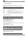
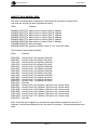
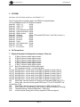
HYTEC ELECTRONICS Ltd HEAD OFFICE: 5 CRADOCK ROAD, READING, BERKS. RG2 0JT, UK Telephone: +44 (0) 118 9757770 Fax: +44 (0)118 9757566 E-mail: [email protected] IOC Blade 9010 1U Rack Mounted Input Output Controller 6 Industry Pack and 1 PMC Carrier Specification Document No: IOC9010/PS/1.5 Date: 11/09/2008 Author: DAN/PM Hytec Electronics Ltd IOC9010/PS/1.5 CONTENTS 1. INTRODUCTION ............................................................................................................................... 3 2. PRODUCT SPECIFICATIONS ........................................................................................................ 3 3. OPERATING MODES ....................................................................................................................... 4 4. APPLICATION REGISTERS ........................................................................................................... 5 5. ID PROM ............................................................................................................................................. 9 6. I/O CONNECTIONS .......................................................................................................................... 9 7. PHYSICAL HARDWARE CONFIGURATION (JUMPERS, POTS ETC) ................................. 9 APPENDIX A ............................................................................................................................................ 10 Idiots Guide to Installing Linux on the 9010 IOC Blade .................................................................... 10 APPENDIX B ............................................................................................................................................ 11 Idiots Guide to Installing EPICS on the 9010 IOC Blade .................................................................. 11 APPENDIX C ............................................................................................................................................ 12 Idiots Guide to Building an EPICS Example ...................................................................................... 12 Quick EPICS Test ................................................................................................................................ 12 APPENDIX D ............................................................................................................................................ 13 Idiots Guide to Installing and Running Medm .................................................................................... 13 Installing the Hytec IOC Blade Linux Kernel 2.6 Driver ................................................................... 14 Writing Your Own IPCard Drivers ..................................................................................................... 14 Introduction ......................................................................................................................................... 14 Page 2 Hytec Electronics Ltd IOC9010/PS/1.5 1. INTRODUCTION The IOC Blade 9010 is a 1U, 19” Rack Mounted Input / Output controller, designed to carry up to 6 Single width Industry Packs (IP) and a single PMC card simultaneously. The logic on the motherboard of the 9010 1U IOC consists of interfacing hardware for the PC104+ processor to the Industry Packs and to the PMC device. Additionally, support is provided for the front panel displays and switches. The interface is in the form of a PLX Technology PCI9030 bridge device and a Xilinx Spartan 2 logic chip. The ‘Local Bus’ side of the 9030 chip is a non-multiplexed microprocessor bus with 32 address lines, 16 data lines and control signals. The PCI clock from the 9030 is used by the Xilinx device for all timing and clock requirements. The 9030 device requests resources from the PC104+ processor as follows: An I/O area for access to the configuration registers (not used). A MEMORY area for access to the configuration registers (not used). An I/O area for access to the internal registers of the Xilinx (Carrier Board registers). A MEMORY area for access to the Industry Packs. This I/O area is 64 bytes wide, organised as 32 16-bit words, starting at offset zero as follows: Offset 0 2 4 6 8 A C E 10 12 14 16 18 1A 1C Name CSR-CB CONFIG DISP_CONT DISP_DATA INTS_LO INTS_HI MASK_LO MASK_HI IP_CLK FAN_1_2 FAN_3_4 FAN_5_6 FAN_CONT TEMP_FLAG CONFIG_2 Description Carrier board Control and Status Register. Carrier Board Switches and settings. Read/write access to the LCD display control register Read/write access to the LCD display data register Read only access to the IP IRQ Status Register (12 bits) Read only access to the IP Error Status Register (7 bits) Read/write access to a mask register for IP IRQ sources Read/write access to a mask register for IP Error sources Read/write access the IP CLOCK SELECT register (6 bits) Read only register showing the speeds of fans 1 & 2 in RPS. Read only register showing the speeds of fans 3 & 4 in RPS. Read only register showing the speeds of fans 5 & 6 in RPS. Read/Write access to Control bits for each fan Read only access to temperature sensor output flags. Read only access to second 8-bit configuration switch pack. 2. PRODUCT SPECIFICATIONS Size: Operating temp: Number of input/outputs: Power: 1U 19” Rack 400mm Deep Approx 0 to 45 deg C ambient 6 SCSI Style Connectors providing connection to the IP Cards. +100 to 240VAC at 47-63Hz 20W Maximum Unpopulated. Page 3 Hytec Electronics Ltd IOC9010/PS/1.5 3. OPERATING MODES There are several basic operating modes set according to the CSR (see below):The 9010 IOC Blade will support the following software / protocols to access hardware input/output. Linux / EPICS The Linux / EPICS version on booting up, will scan all the Industry Pack (IP) slots and using the ‘VITA4’ standard it will identify the cards fitted. From this scan it will set up a default start up script, which will configure the cards and set up a default EPICS database. This will allow EPICS users via straight CA (Channel Access), EDM, MEDM and other EPICS utilities to immediately access the IOC’s interfaces, without the need to configure. The user can modify the start up script via the HTML pages (see below) or directly on the Compact Flash, to more specifically configure any IP Card. The modified start up script will always take priority over the default start up script, unless there is a configuration error i.e. any IP Cards are absent or changed. Linux / HTML With the Linux version it is possible with a web browser, to simply enter the IP address and access a tabbed HTML page. There is a page for each Industry Pack slot together with a general configuration tab etc. The layout of the tabbed page is adjusted for each type of IP card. This will allow developers to easily configure IOCs from their default settings. Since HTML allows IP Cards’ inputs to be monitored and outputs modified, the HTML interface allows the IOC Blade to be easily used for remote testing with no client code at all. Linux / TCP/IP The Linux version will also support a specific TCP/IP Socket, which will accept a standard TCP/IP connection. Via this connection, simple commands (STATUS, CONFIGURE, READ, WRITE etc) will allow full access and control to the IOC Blades IP Cards. A document fully describing the protocol is available on the Hytec Electronics Ltd website. This will allow Visual Studio, Borland, Delphi, and LabView and any C++ developers to easily interface to the IOC, and produce their own control packages. RTEMS / EPICS The 9010 IOC Blade can be run in the same way that the more usual VxWorks IOC would be, i.e. it boots up, connects to a host and runs off a start up script. RTEMS versions of the drivers are available from the Hytec Electronics Ltd website. Windows / OPC Server The 9010 IOC Blade will also support OPC server running on the Windows CE operating system, and the Industry Pack (IP) cards will appear as OPC devices. Any industry SCADA systems or applications with OPC client integrated would be able to easily read/write data from/to the devices. This OPC server will be fully compliant with the most current version of the OPC specification. During the system boot, a start up program will scan the devices connected automatically and build up a basic configuration database. A configuration tool (Either a Windows application or via the web browser) will be provided should the user change the device settings or the Industry Pack (IP) cards. Page 4 Hytec Electronics Ltd IOC9010/PS/1.5 4. APPLICATION REGISTERS Carrier Board Control/Status Register CSR-CB Address 0h (Read/Write) Address: Base + 0x0 D15 D14 D13 D12 D11 D10 D09 0 0 0 FCON 0 TP16 TP15 FAN_6 FAN_5 FAN_4 FAN_3 FAN_2 FAN_1 PMC TIMO FAN_1-6 TP15-16 FCON D08 D07 D06 D05 D04 D03 D02 D01 D00 0 TIMO PMC a ‘1’ indicates a valid PMC card detected a ‘1’ indicates the last attempted access to an IP card timed out. This bit is cleared by writing a ‘1’ to it. a ‘1’ indicates detected fan rotation (see also fan control monitoring registers). from on-board test points (with pull-ups) inverted, so normally ‘0’. one writeable and readable bit to select the cooling fan control method. ‘0’ = local automatic control, ‘1’ = remote control through the register at offset 18 HEX. CONFIG (Offset 2h) [Read only] D15 D14 D13 D12 D11 D10 D09 D08 D07 D06 D05 D04 D03 D02 D01 D00 SW1 SW1 SW1 SW1 SW1 SW1 SW1 SW1 SP_ SP_ SP_ SP_1 RES DOW OK UP /7 /6 /5 /4 /3 /2 /1 /0 4 3 2 ET N UP/OK/DOWN/RESET from front panel switches. SP_1-4 from spare on-board switch points. SW1/0-7 from 8-way switch pack A. DISPLAY CONTROL/DATA. (Offsets 4h, 6h) Registers for direct R/W access to the front panel LCD display. The Control register is at offset 4h, and the Data register at offset 6h. INTERRUPTS LOW. (Offset 8h) [Read only] D15 D14 D13 D12 D11 X X X X INT RE Q F1 D10 INT RE Q F0 D09 INT RE Q E1 D08 INT RE Q E0 D07 INT RE Q D1 D06 INT RE Q D0 D05 INT RE Q C1 D04 INT RE Q C0 D03 INT RE Q B1 D02 INT RE Q B0 D01 INT RE Q A1 D00 INT RE Q A0 Bits showing the states of two IP Interrupt output lines for all 6 industry packs. INTERRUPTS HIGH. (Offset Ah) [Read only] D15 D14 D13 D12 D11 D10 D09 D08 D07 D06 D05 D04 D03 D02 D01 D00 Page 5 Hytec Electronics Ltd X X X X IOC9010/PS/1.5 X X X TIM O X X ERR ERR ERR ERR ERR ERR _ F _E _D _C _B _A Bits showing the state of IP Error outputs for all 6 industry packs plus one bit for the IP access timeout flag to allow an interrupt to be generated from it. MASK LOW/HIGH (Offsets Ch, Eh) Registers corresponding to Interrupt and Error flag bits in INTS LO & INTS HI above, to select which, if any, are permitted to produce a PC104+ processor interrupt. This interrupt is presented to the PC104+ card on PCI interrupt INTA#. IP CLOCK SELECT. (Offset 10h) D15 D14 D13 D12 D11 D10 D09 D08 D07 D06 D05 D04 D03 D02 D01 D00 X X X X X X X X X X CKS CKS CKS CKS CKS CKS _ F _E _D _C _B _A Bits to select the clock frequency for each Industry Pack. ‘1’ = 32MHz, ‘0’ = 8MHz.These bits all default to ‘0’ on power-up. FANS_1_2. (Offset 12h) [Read only] D15 D14 D13 D12 D11 D10 D09 D08 D07 D06 D05 D04 D03 D02 D01 D00 F2_ F2_ F2_ F2_ F2_ F2_ F2_ F2_ F1_ F1_ F1_ F1_ F1_ F1_ F1_ F1_ 7 6 5 4 3 2 1 0 7 6 5 4 3 2 1 0 F1_0-7 represent the rotation speed of fan 1 in eight bit binary form, indicating the speed in revolutions per second. F2_0-7 show the same for fan 2. FANS_3_4. (Offset 14h) [Read only] D15 D14 D13 D12 D11 D10 D09 D08 D07 D06 D05 D04 D03 D02 D01 D00 F4_ F4_ F4_ F4_ F4_ F4_ F4_ F4_ F3_ F3_ F3_ F3_ F3_ F3_ F3_ F3_ 7 6 5 4 3 2 1 0 7 6 5 4 3 2 1 0 As for FANS_1_2 but for fans 3 and 4. FANS_5_6. (Offset 16h) [Read only] D15 D14 D13 D12 D11 D10 D09 D08 D07 D06 D05 D04 D03 D02 D01 D00 F6_ F6_ F6_ F6_ F6_ F6_ F6_ F6_ F5_ F5_ F5_ F5_ F5_ F5_ F5_ F5_ 7 6 5 4 3 2 1 0 7 6 5 4 3 2 1 0 Page 6 Hytec Electronics Ltd IOC9010/PS/1.5 As for FANS_1_2 but for fans 5 and 6. Note that fan 6 is optional to cool the PMC card. When not fitted, Fan 6 speed will read as zero. FAN_CONT. (Offset 18h) D15 D14 D13 D12 D11 D10 D09 D08 D07 D06 D05 D04 D03 D02 D01 D00 x x x x x x F5_ F5_ F4_ F4_ F3_ F3_ F2_ F2_ F1_ F1_ B A B A B A B A B A Cooling Fan Control and Status Register. The unit has five cooling fans which can be controlled to be either off, half speed or full speed. This register has ten active bits, two for each fan. The ‘A’ bit controls the low speed option: ‘0’ = OFF; ‘1’ = ON. The ‘B’ bit controls the high speed option: ‘0’ = OFF; ‘1’ = ON. Note that when the high speed bit is set for a fan, the low speed bit becomes ‘don’t care’. Thus bit 5, F3_B controls the high speed option of fan number 3. This register is controlled by the FAN MODE bit of the CSR_CB; when this bit is zero, fan control is automatic, based on the signals from the temperature sensors, and reading this register will show how the fans are being operated. Writing to this register in this mode has no effect. When the FAN MODE bit in CSR_CB is written as ‘1’, this register is used to control the fans and will read back what is written. However, when in this mode, if any of the temperature sensors indicates that the unit is overheating, remote mode is overridden and local automatic control resumes. TEMP_FLAG (Offset 1Ah) [Read only] D15 D14 D13 D12 D11 D10 D09 D08 D07 D06 D05 D04 D03 D02 D01 D00 x TE_H TE_M TE_L TD_H TD_ TD_L TC_H TC_ TC_L TB_H TB_M TB_L TA_H TA_M TA_L I D O I MD O I MD O I D O I D O This register shows the state of the temperature sensors in the unit. Each of the five sensors has three output flags for low, middle and high alarm states. The sensors are referred to as TATE and the flags as LO (low) MD (mid) and HI (high). In automatic mode (see Fan Control register above) the LO bit of each of these sensors is used to turn the associated fan on in low speed mode. The MD bit controls the high speed mode of that fan and any of the HI bits appearing will cause all five fans to go into high speed mode. CONFIG_2 (Offset 1Ch) [Read only] D15 D14 D13 D12 D11 D10 D09 D08 D07 D06 D05 D04 D03 D02 D01 D00 x x x x x x x x SW2 SW2 SW2 SW2/ SW2/ SW2/ SW2/ SW2 /8 /7 /6 5 4 3 2 /1 SW1/1-8 from 8-way switch pack B. Page 7 Hytec Electronics Ltd IOC9010/PS/1.5 INDUSTRY PACK MEMORY AREA. This area is 16 Mbytes wide, organised as 16-bit words. All accesses to Industry Pack resources are through this area, organised as follows: Offset Contents 0000000h-01FFFFEh 0200000h-03FFFFEh 0400000h-05FFFFEh 0600000h-07FFFFEh 0800000h-09FFFFEh 0A00000h-0BFFFFEh 0C00000h-0DFFFFEh 0E00000h-0E00FFEh Memory area of Industry Pack A, 2Mbytes. Memory area of Industry Pack B, 2Mbytes. Memory area of Industry Pack C, 2Mbytes. Memory area of Industry Pack D, 2Mbytes. Memory area of Industry Pack E, 2Mbytes. Memory area of Industry Pack F, 2Mbytes. Not used (spare). Access to Industry Packs A-F I/O, ID and INT areas. This last area is sub-divided as follows: Offset Contents 000h-07Eh 080h-0FEh 100h-17Eh 180h-1FEh 200h-27Eh 280h-2FEh 300h-37Eh 380h-3FEh 400h-47Eh 480h-4FEh 500h-57Eh 580h-5FEh 600h-7FEh 800h-8FEh 900h-9FEh A00h-AFEh B00h-BFEh C00h-CFEh D00h-DFEh E00h-FFEh Industry Pack A I/O registers (64 bytes). Industry Pack A ID registers (64 bytes). Industry Pack B I/O registers (64 bytes). Industry Pack B ID registers (64 bytes). Industry Pack C I/O registers (64 bytes). Industry Pack C ID registers (64 bytes). Industry Pack D I/O registers (64 bytes). Industry Pack D ID registers (64 bytes). Industry Pack E I/O registers (64 bytes). Industry Pack E ID registers (64 bytes). Industry Pack F I/O registers (64 bytes). Industry Pack F ID registers (64 bytes). Not used Industry Pack A INT registers (128 bytes, only 2 words used). Industry Pack B INT registers (128 bytes, only 2 words used). Industry Pack C INT registers (128 bytes, only 2 words used). Industry Pack D INT registers (128 bytes, only 2 words used). Industry Pack E INT registers (128 bytes, only 2 words used). Industry Pack F INT registers (128 bytes, only 2 words used). Not used. Note: for this last set of registers, an access at the base address requests the vector for IP Interrupt 0, and at base address plus two, the vector for Interrupt 1. All other addresses are not used. Page 8 Hytec Electronics Ltd IOC9010/PS/1.5 5. ID PROM Should the 9010 IOC Blade should have an ID PROM ????? The ID configuration information held in the PROM is as detailed below. The byte addresses of the ID PROM are as below:Base+80 ASCII ‘VI’ 5649h Base+82 ASCII ‘TA’ 5441h Base+84 ASCII ‘4 ‘ 3420h Base+86 Hytec ID high byte 0080h Base+88 Hytec ID low word 0300h Base+8A Model number 8505h Base+8C Revision 2201h (This shows PCB Issue 2 and Xilinx at issue 1 ) Base+8E Reserved 0000h Base+90 Driver ID 0000h Base+92 Driver ID 0000h Base+94 Flags 0002h Base+96 No of bytes used 001Ah Base+98 Not used 0000h Base+9A Serial Number xxxxd 6. I/O Connections 7. Physical Hardware Configuration (Jumpers, Pots etc) J1 IP Slot A Common strobe signal connect. J2 IP Slot B Common strobe signal connect. J3 IP Slot C Common strobe signal connect. J4 IP Slot D Common strobe signal connect. J5 IP Slot E Common strobe signal connect. J6 IP Slot F Common strobe signal connect. J7,J9 Boot Xilinx when made (normally both made) J8 Set Temperature Range – not normally fitted J10-J15 Normally fitted – can be used to feed PMC IO signals to Industry Pack A. J16-J21 Normally fitted – can be used to feed PMC IO signals to Industry Pack B. J22-J27 Normally fitted – can be used to feed PMC IO signals to Industry Pack C. J28-J33 Normally fitted – can be used to feed PMC IO signals to Industry Pack D. J34-J39 Normally fitted – can be used to feed PMC IO signals to Industry Pack E. J40-J45 Normally fitted – can be used to feed PMC IO signals to Industry Pack F. J46 When fitted, connects common IP strobe line to rear panel LEMO input (TTL). J47 When fitted, connects the rear panel LEMO input (TTL) to PC104 RESET via connections at J48. J49 When fitted, connects common IP strobe line to a PMC IO signal (TTL). VR1 Front Panel LCD Contrast Adjust (this is factory adjusted for optimum Viewing). VR2 Temperate Sensor reference adjustment – factory set. VR3 Low Fan Speed Setting (this is factory adjusted to 5000 rpm approx). Page 9 Hytec Electronics Ltd IOC9010/PS/1.5 APPENDIX A Idiots Guide to Installing Linux on the 9010 IOC Blade 1. Install Linux, we usually use Scientific Linux 4, the base SL distribution of which is basically Enterprise Linux, recompiled from source. We have found particulary hassle free. For more information and copies of the operating system please go to https://www.scientificlinux.org/. Which ever version of Linux you want to use, it MUST have a 2.6 Kernel if you want to do any work with the Hytec IOC Blade 9010. As its PCI interface code is presently only supported with this Kernel. 2. 3. 4. 5. Select Installation Language (e.g. English(English) ). Select Keyboard (e.g. United Kingdom). Select Mouse (it will indicate what you are presently using, so normally just click on next). Partition Disk (Automatic is OK in most cases). If you are installing onto some sort of restricted system, such as a Flash Disk on a PC104, you need… /boot – 76Mb on ext3 – Force to be Primary Partition. 250Mb on swap. Can be less but get it as close to this as possible. / - Rest of the Disk (i.e. Fill all available space). 6. (Linux Text install) Select use GRUB Boot Loader. 7. (Linux Text install) Enter Boot Loader special options, normally leaving blank is usually fine. 8. (Linux Text install) Enter Boot Loader Password, normally leaving blank is usually fine. 9. (Linux Text install) Add other operating system to Boot Loader if required. 10. (Linux Text install) Select installing Boot Loader on to Master Boot Record (MBR). 11. Network Configuration (Automatically by DHCP is OK in most cases). 12. Firewall Configuration, either have No Firewall or preferably Enable Firewall under ‘Other ports’ entry box list the EPICS ports i.e. ‘5064:tcp,5065:tcp,5064:udp,5065:udp’. 13. Add any language support required. 14. Select Time Zone. 15. Enter root password and confirm. 16. (Linux Text install) If you are installing onto some sort of restricted system, such as a Flash Disk on a PC104, you need to use ‘customize software selection’ and at least include (as a minimum for EPICS)… Development Tools. Kernel Development. Legacy Software Development. 17. Insert CD 2 to 4 as requested. 18. Graphical Interface Configuration (it will indicate what you are presently using, so normally just click on next). 19. Monitor Configuration (it will indicate what you are presently using, so normally just click on next). 20. Customize Graphics Configuration (it will indicate what you are presently using, so normally just click on next, restriction for PC104). 21. Agree to License. 22. Set Date and Time. 23. Add user. 24. Skip additional CD Installation. Page 10 Hytec Electronics Ltd IOC9010/PS/1.5 APPENDIX B Idiots Guide to Installing EPICS on the 9010 IOC Blade All previously released versions of Base are now publicly available, including a nightly snapshot of the R3-14 branch of the EPICS CVS repository. To discover the size of the download files in advance, visit the Base Download area. The tar file linked below contains source code only (no binaries), and was compressed using gnuzip. baseR3.14.8.2.tar.gz 1. 2. 3. 4. 5. Gotohttp://www.aps.anl.gov/epics/base/R3-14/6.php load ‘baseR3.14.8.2.tar.gz’ to /usr/local/EPICS. Make the directory if necessary(i.e. mkdir). Unzip it (i.e. gunzip baseR3.14.8.2.tar.gz). Expand it (i.e. tar xvf baseR3.14.8.2.tar). Before you can build or use EPICS, you must set a couple of environment variables This can be done by either simply typing the two commands (i.e. export EPICS_HOST_ARCH=linux-x86 export EPICS_BASE=/usr/local/EPICS/base-3.14.8.2) or by modifying the bash shell. To edit the bash shell (Linux default shell), you need to edit the hidden file .bash_profile (can be seen with ls –al from /root) and modify to something like below . The important additions are highlighted…. # .bash_profile # Get the aliases and functions if [ -f ~/.bashrc ]; then . ~/.bashrc fi # User specific environment and startup programs PATH=$PATH:$HOME/bin BASH_ENV=$HOME/.bashrc USERNAME="root" EPICS_HOST_ARCH=linux-x86 EPICS_BASE=/usr/local/EPICS/base-3.14.8.2 export USERNAME BASH_ENV PATH EPICS_HOST_ARCH EPICS_BASE 6. Move to the build directory containing the EPICS make file (i.e cd /usr/local/EPICS/base3.14.8.2). 7. make EPICS (i.e. make). Page 11 Hytec Electronics Ltd IOC9010/PS/1.5 APPENDIX C Idiots Guide to Building an EPICS Example 1. Make a directory under your root, suitably named for the example you wish to build (i.e. mkdir IOCBlade9010). 2. Change to this newly created directory (i.e. cd IOCBlade9010).. 3. Call a script to build an example, in the following command ‘-t example’ is telling it to build an example type script and IOC9010 is its name (i.e. /usr/local/EPICS/base3.14.8.2/bin/linux-x86/makeBaseApp.pl -t example IOC9010) 4. Run a second script (i.e. /usr/local/EPICS/base-3.14.8.2/bin/linux-x86/makeBaseApp.pl -i -t example IOC9010). 5. make (i.e. make) 6. Under your example directory, the directory structure /iocBoot/’ioc + Example Name’ will have been added. Change to this sub-directory (i.e. cd iocBoot/iocIOC9010). 7. This directory contains a script (st.cmd) this files need to be made executable (i.e. chmod 777 st.cmd). 8. run it (i.e. ./st.cmd). 9. Typing the command ‘dbl’ will list the Quick EPICS Test 1. cd/usr/local/EPICS/base-3.14.8.2/bin/linux-x86 2. ./caRepeater& 3. ./caget IOC:aiChannel1 Page 12 Hytec Electronics Ltd IOC9010/PS/1.5 APPENDIX D Idiots Guide to Installing and Running Medm 1. Go to web site http://www.aps.anl.gov/epics/download/extensions/index.php 2. Download the following three files and copy them into base directory /usr/local/EPICS/base3.14.8.2 medm3_0_3.tar.gz extensionsConfig_20040406.tar.gz extensionsConfigure_20040406.tar.gz 3. Extract all three files from there. This will build the extension structures. 4. Find the file RELEASE in the… /usr/local/EPICS/base-3.14.8.2/extensions/config directory and open it by editor. Change the line EPICS_BASE= to the current base directory i.e. using a text EPICS_BASE=/usr/local/EPICS/base-3.14.8.2 And save it. Do the same change to the RELEASE file in the /usr/local/EPICS/base3.14.8.2/extensions/configure directory and save it. 5. Go to medm subdirectory by typing: cd /usr/local/EPICS/base-3.14.8.2/extensions/src/medm 6. Build medm by doing a make, i.e. simply type… Make This will take possibly half an hour to build the medm depending on the speed of your machine. 7. Once the build is complete, to run medm simply change to directory…. cd /usr/local/EPICS/base-3.14.8.2/extensions/src/medm/medm/0.linux-x86 8. Then Run it, i.e. simply type… ./medm 9. If you have an example to run, simply use the mouse to click on FILE -> OPEN and navigate for the example display file (*.adl is the normal extension). 10. To run it, click on the ‘Execute’ button. Page 13 Hytec Electronics Ltd IOC9010/PS/1.5 Installing the Hytec IOC Blade Linux Kernel 2.6 Driver 1. As you are installing / running some kernel level code, you will find it it much easier to log on as root. Also this Driver is for a Linux Kernel 2.6 Version only (such as found with Scientific Linux 4.0). 2. Go to web site http://www.hytec-electronics.co.uk/xxxxxxx/ 3. Download the file IOCBlade9010.tar.gzip and copy it into the root directory… /root 4. Extract it in this location. 5. This is an EPICS example application and also includes a copy of the Hytec IOC Blade Linux Kernel 2.6 Driver under the Directory… /root/IOCBlade9010/pci 6. To install the driver simply type.. /root/IOCBlade9010/pci/IOC9010_load Writing Your Own IPCard Drivers Introduction The Directory /root/IOCBlade9010/pci contains the Hytec IOC Blade 9010 Linux Kernel Driver. This Directory includes the driver itself, load / unload scripts and a header file to allow you to access the IP Cards and the actual IOC Blade 9010 Registers. The driver provides functions that use stream like operations, so you for instance read the ID PROM of the IP Card in Site A… /* Open the Stream */ IOCHandle = open("/dev/IOC9010",0); if (IOCHandle = = -1) printf("9010: Error Opening Device !\n"); /* Set up the Data Structure */ ioctl_buf.lAddress = IP_A_ID_BASE_ADDR + ID_MODEL_NUMBER; ioctl_buf.lLength = 1; ioctl_buf.sData = (unsigned long)(&data); /* Read IP Card Type from ID PROM */ *val = ioctl(IOCHandle, OP_GENERAL_READ, &ioctl_buf); printf("IP Slot %c = %4X\n", 'A', *val); /* Close the Stream */ close(IOCHandle); or reading the first 5 registers on the 8505 IP Card in Slot C… IOCTL_BUF ioctl_buf; unsigned short data = value; unsigned short readbuffer[5]; int IOCHandle; IOCHandle = open("/dev/IOC9010",0); if (IOCHandle == -1) printf("8505: Error Opening Device !\n"); /* 8505 Basic Digital Output Setup */ Page 14 Hytec Electronics Ltd IOC9010/PS/1.5 ioctl_buf.lAddress = IP_C_IO_BASE_ADDR; ioctl_buf.lLength = 5; ioctl_buf.sData = (unsigned long)(readbuffer); ioctl(IOCHandle, OP_GENERAL_READ_BLOCK, &ioctl_buf); close(IOCHandle); Page 15